Powerwave Technologies S21008 Masthead amplifier enhances performance of PCS, PC User Manual Installation and Operating Manual
Powerwave Technologies, Inc. Masthead amplifier enhances performance of PCS, PC Installation and Operating Manual
Installation and Operating Manual
INSTALLATION AND OPERATING
MANUAL
98/OSM/0019
ISSUE 1
13/04/99
Airtech DCS1800 / PCS1900 Booster System Installation and Operating Manual Page 1 of 25
DCS 1800 / PCS 1900 BOOSTER SYSTEM
INSTALLATION AND OPERATING MANUAL
The information contained in this document is furnished in commercial confidence and upon the condition that the
individual and corporate rights originating in the information, whether patented or not, will be respected.
Reference; 98/OSM/0019 Issue: 1 Date: 13/04/99
Prepared by:
Mark Billsberry
Authorised by Engineering: Authorised by Quality:

INSTALLATION AND OPERATING
MANUAL
98/OSM/0019
ISSUE 1
13/04/99
Airtech DCS1800 / PCS1900 Booster System Installation and Operating Manual Page 2 of 25
HISTORY
DATE ISSUE AUTHOR MOD/ISSUE
NOTE NOTES
13/04/99 1 Mark Billsberry MI0167 Original Issue

INSTALLATION AND OPERATING
MANUAL
98/OSM/0019
ISSUE 1
13/04/99
Airtech DCS1800 / PCS1900 Booster System Installation and Operating Manual Page 3 of 25
CONTENTS
1. INTRODUCTION 4
2. TECHNICAL DESCRIPTION OF BOOSTER SYSTEM EQUIPMENT 5
3. INTERFACE DETAILS 7
4. INSTALLATION OF THE BOOSTER SYSTEM 19
5. COMMISSIONING 24
Figure 1 Interface Drawing for the Booster ..........................................................................7
Figure 2 Interface Drawing for the Booster ..........................................................................8
Figure 3 Interface Drawing for the Booster External Bias Tee...........................................10
Figure 4 Interface Drawing for the Variable Gain G3 MHA..............................................11
Figure 5 Interface Drawing for the Indoor Variable Gain MHA Bias Tee .........................13
Figure 6 Interface Drawing for the Outdoor Variable Gain MHA Bias Tee ......................14
Figure 7 Interface Drawing for the PDU with Wall Mounted Bracket...............................17
Figure 8 Interface Drawing for the PDU with Pole Mounted Bracket................................18
Figure 9 Booster System Connectivity ...............................................................................23

INSTALLATION AND OPERATING
MANUAL
98/OSM/0019
ISSUE 1
13/04/99
Airtech DCS1800 / PCS1900 Booster System Installation and Operating Manual Page 4 of 25
1. Introduction
Airtech produce a range of masthead amplifier and associated equipment to provide
enhancement of the performance of PCS, PCN, and GSM Base-stations (BTS ).
The limitation of the BTS has traditionally been its sensitivity to the Uplink, or received
signal at the BTS. The antenna receives the signal from the mobile, but this can be
degraded by the feeder cable losses from the antenna down the mast to the BTS. The
Airtech Masthead Amplifier employs a low noise amplifier to transmit the improved signal
strength down to the BTS overcoming the signal degradation due to the feeder cable
losses.
The result is a greater sensitivity of the receive system, providing better quality, greater
coverage and generally fewer dropped calls, as well as reducing the power required by the
mobile phone from any particular location which may increase the battery life and general
user satisfaction with the network.
The Airtech Booster is designed to increase the downlink signal level by placing the high
power amplifiers at the masthead reducing the feeder losses. This extends the range of the
base station further, reducing infrastructure costs or improving coverage in black spots.
CAUTION:
PRIOR TO WORKING ON OR INSTALLING THE BOOSTER SYSTEM OR
ANY OF ITS COMPONENTS, ENSURE THAT THE BTS TRANSMITTER RF
OUTPUT IS TURNED OFF AND THAT PRECAUTIONS ARE TAKEN TO
ENSURE THAT THE TRANSMITTER CANNOT BE ACTIVATED DURING
THE EQUIPMENT INSTALLATION.
THERE ARE NO USER SERVICABLE COMPONENTS INSIDE THE
BOOSTER. RETURN THE UNIT TO THE FACTORY IF SERVICE OR REPAIR
IS REQUIRED.

INSTALLATION AND OPERATING
MANUAL
98/OSM/0019
ISSUE 1
13/04/99
Airtech DCS1800 / PCS1900 Booster System Installation and Operating Manual Page 5 of 25
2. Technical Description of Booster System Equipment
The booster system consists of the following units:
• Booster
• Booster Bias Tee
• Variable Gain G3 Masthead Amplifier (Optional)
• Variable Gain Masthead Amplifier Compatible Bias Tee (Optional)
• Booster System Power Distribution Unit
• Connecting Cables
2.1 Booster
The Booster is designed for masthead operation. It includes a variable gain transmit high
power amplifier and a variable high gain LNA. The gain settings are controlled by a micro-
controller via a serial data link with the Power Distribution Unit.
The Booster is designed to interface with duplexing feeds to both the antenna and the Base
Station. The RF, DC power (+30V ) and serial data link are all fed to the booster through
the RF coaxial feeder cable.
The Booster is housed in a weatherproofed enclosure rated to IP68, with a 7/16 RF
connector for the ANT at the top and a 7/16 RF connector for the BTS at the base. There
is also a grounding stud mounted on the base used for grounding the Booster to the mast,
and provides the discharge path for the lightning protection circuit.
2.2 Booster Bias Tee
The Booster Bias Tee performs four functions within the booster system. A straight
through path is provided for RF signals, the DC power from the PDU is injected onto the
feeder and the serial communications to/from the booster is taken from the feeder and
supplied to the PDU. The Bias Tee also provides lightning protection for the BTS and
PDU.
2.3 Variable Gain G3 Masthead Amplifier
The Airtech Variable Gain G3 MHA M-series single feeder is designed to deliver up to
22dB Rx gain, low Tx loss and low Rx noise figure in a compact low volume and light
weight IP68 enclosure. The MHA-M series single feeder is designed to interface with
duplexing feeds to both the antenna and the Base Station.
The MHA is housed in a weatherproofed enclosure, with a 7/16 RF connector for the ANT
at the top and a 7/16 RF connector for the BTS at the base. There is also a grounding stud
mounted on the base used for grounding the MHA to the mast, and provides the discharge
path for the lightning protection circuit of the MHA.
The Variable Gain G3 unit requires a +12V supply from the power distribution unit (PDU)
at the base station. This is supplied to the G3 MHA via the RF coaxial feeder cable.
INSTALLATION AND OPERATING
MANUAL
98/OSM/0019
ISSUE 1
13/04/99
Airtech DCS1800 / PCS1900 Booster System Installation and Operating Manual Page 6 of 25
2.4 Variable Gain G3 MHA Bias Tee
The Variable Gain G3 MHA Bias Tee performs the same functions as the Booster bias tee
although it is not capable of handling the current requirements of the booster. The Variable
Gain G3 MHA Bias Tee uses one connector for both the DC power and the serial
communications. A standard G3 Bias Tee should not be used in conjunction with the
Variable Gain G3 MHA since it will block the serial communication interface with the
PDU.
2.5 Power Distribution Unit
The Power Distribution Unit (PDU) converts the input supply to the +30V DC for the
Boosters and the +12V DC for the MHAs. The PDU also generates an internal +5V DC
supply used to drive the control and status panel integrated into the PDU. The PDU can
supply, control and display the status of three boosters and six Variable Gain G3 MHAs.
The PDU reports the status of up to three Boosters and six Masthead Amplifiers and can
also set the Tx and Rx gains for each sector independently. The Booster PDU is only
designed to be used in conjunction with the Variable Gain G3 MHA.
It is important to ensure that the base station supply is within the voltage limits required by
the Booster PDU and that it is capable of providing the power. The power requirements
can be calculated using the table below.
Supply Voltage Limits
AC Input Option 85 Vrms to 264Vrms - 47Hz to 63Hz
DC Input Option -36V to -72V
Power Supply Requirements AC Option DC Option
Per Booster 300W 250W
Per Masthead Amplifier 5W 5W
2.6 Cables
The following three cables are required in order to connect the booster system:
PDU to BTS -48V DC supply ( DC input PDU only )
PDU to Booster Bias Tee DC supply
PDU to Booster Bias Tee ( Serial Data )
PDU to MHA Bias Tee
In addition to these supplied cables, a number of RF jumper cables will be required to
connect the booster to the antenna and BTS to the Bias Tee.
INSTALLATION AND OPERATING
MANUAL
98/OSM/0019
ISSUE 1
13/04/99
Airtech DCS1800 / PCS1900 Booster System Installation and Operating Manual Page 7 of 25
3. Interface Details
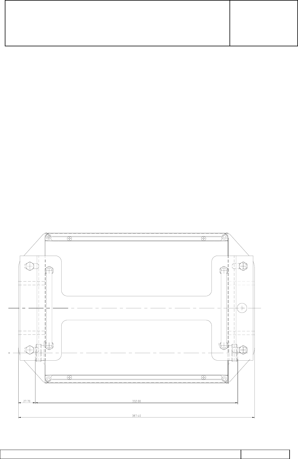
3.1 Booster
The Booster is provided with the following electrical interfaces:
7/16 DIN Female (BTS) on the base. This is the connection for the duplexed Tx/Rx
signals to/from the BTS. As well as providing for RF transmission, this connector also
provides for DC feed and the communication interface via the RF cable and Bias Tee
assembly.
7/16 DIN Female (ANT) on the top. This is the connection for the Tx/Rx Antenna. This
port should be as close as possible to the antenna with the shortest/lowest loss
interconnecting cable practicable.
M8 Ground Stud on the base. This provides the Primary Lightning protection ground to
the Booster. The ground cable should be of the largest cross sectional area, shortest length
practicable and be connected to a suitable grounding point on the mast structure.
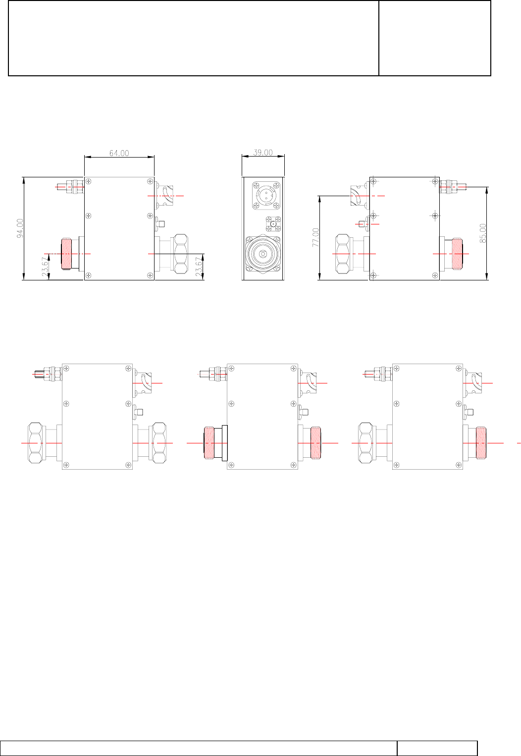
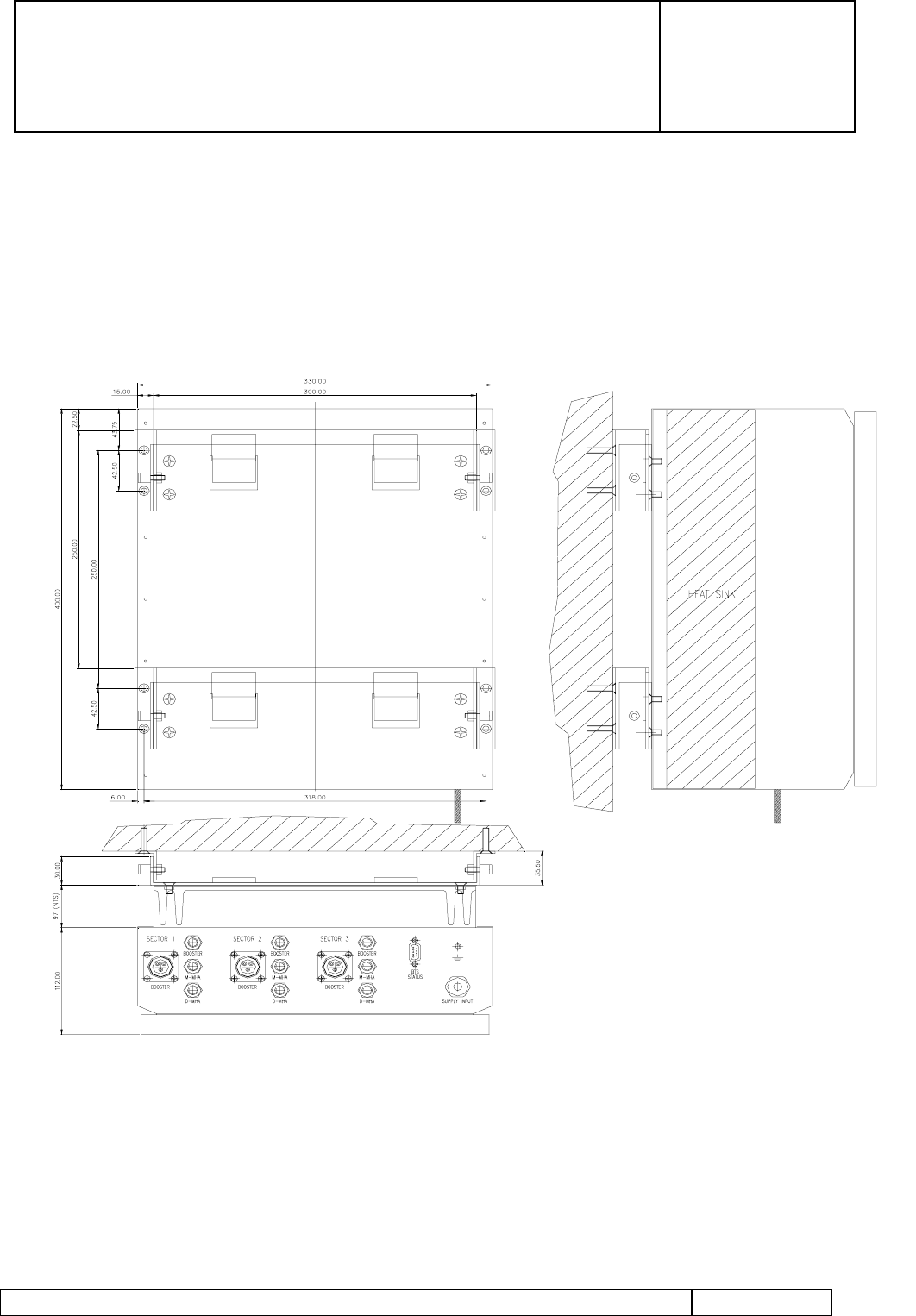
Figure 1 Interface Drawing for the Booster
INSTALLATION AND OPERATING
MANUAL
98/OSM/0019
ISSUE 1
13/04/99
Airtech DCS1800 / PCS1900 Booster System Installation and Operating Manual Page 8 of 25
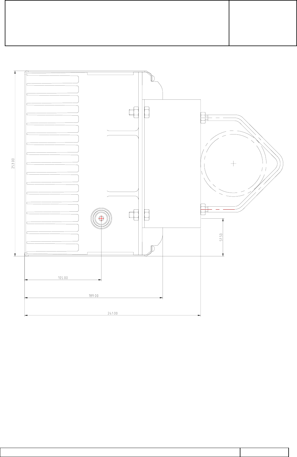
Figure 2 Interface Drawing for the Booster
3.2 Booster Bias Tee
The Booster Bias Tee is provided with the following electrical interfaces.
7/16 DIN Female (Antenna Port). This is the connection for RF feeder up the mast to the
Booster and Antenna. As well as providing for the RF receive and transmit signal, this
connector also provides for DC feed and the communication interface via the centre pin of
the 7/16” connector. It is labelled ANT.
7/16 DIN Male (BTS Port). This is the connection for RF jumper from the Base-station
Transceiver. It is labelled BTS.

INSTALLATION AND OPERATING
MANUAL
98/OSM/0019
ISSUE 1
13/04/99
Airtech DCS1800 / PCS1900 Booster System Installation and Operating Manual Page 9 of 25
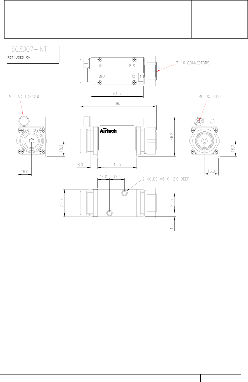
SMA Female. This is the connector for the serial communications interface from the
Airtech Booster System PDU. It is labelled COMMS.
MIL 5015 10SL4-PSN DC Power Connector. This is the connector for the DC power input
from the Airtech Booster System PDU via a cable supplied by Airtech. The B pin on the
connector has the 30VDC supply. It is labelled DC.
M6 Ground Stud. This provides the Primary Lightning protection ground to the Bias Tee.
The ground cable should be of the largest cross sectional area, shortest length practicable
and be connected to a suitable grounding point. Failure to connect this to an adequate
Ground may result in damage to the Booster System components in the event of high
EMFs being generated in the RF Feeder line during lightning strikes.
The specification of the sex and type of the RF connectors can be altered by special
request. Please contact Airtech for further details if this is required.
3.3 Variable Gain G3 Masthead Amplifier
The MHA is provided with the following electrical interfaces:
7/16 DIN Female (BTS) on the base. This is the connection for the duplexed Tx/Rx
signals to/from the BTS. As well as providing for RF transmission, this connector also
provides for DC feed and the communication interface via the RF cable and Bias Tee
assembly.
7/16 DIN Female (ANT) on the top. This is the connection for the Tx/Rx Antenna. This
port should be as close as possible to the antenna with the shortest/lowest loss
interconnecting cable practicable.
M8 Ground Stud on the base. This provides the Primary Lightning protection ground to
the MHA. The ground cable should be of the largest cross sectional area, shortest length
practicable and be connected to a suitable grounding point on the mast structure.
INSTALLATION AND OPERATING
MANUAL
98/OSM/0019
ISSUE 1
13/04/99
Airtech DCS1800 / PCS1900 Booster System Installation and Operating Manual Page 10 of 25
Interface Drawing
Connector Options
Figure 3 Interface Drawing for the Booster External Bias Tee
INSTALLATION AND OPERATING
MANUAL
98/OSM/0019
ISSUE 1
13/04/99
Airtech DCS1800 / PCS1900 Booster System Installation and Operating Manual Page 11 of 25
Figure 4 Interface Drawing for the Variable Gain G3 MHA

INSTALLATION AND OPERATING
MANUAL
98/OSM/0019
ISSUE 1
13/04/99
Airtech DCS1800 / PCS1900 Booster System Installation and Operating Manual Page 12 of 25
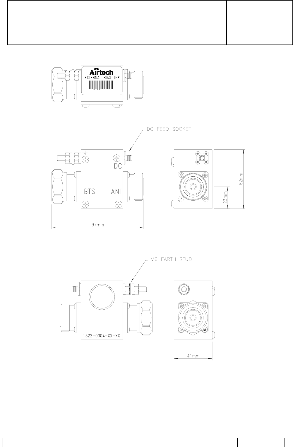
3.4 Variable Gain G3 Bias Tee
The Bias Tee is provided with the following electrical interfaces:
7/16 DIN Female (Antenna Port). This is the connection for RF feeder up the mast to the
MHA and antenna. As well as providing for the RF receive and transmit signal, this
connector also provides for DC feed and the communication interface via the centre pin of
the 7/16” connector. It is labelled MHA.
7/16 DIN Male (BTS Port). This is the connection for RF jumper from the BTS. It is
labelled BTS.
SMA DC Power Connector. This is the connector for the DC power input from the
Airtech PDU via a cable supplied by Airtech. This connector has the MHA supply and
communications interface on the centre pin of this co-axial connector.
M6 Ground Stud. This provides the Primary Lightning protection ground to the Bias Tee.
The ground cable should be of the largest cross sectional area, shortest length practicable
and be connected to a suitable grounding point. Failure to connect this to an adequate
Ground may result in damage to the Bias Tee in the event of high EMFs being generated in
the RF Feeder line during lightning strikes.
The specification of the sex and type of the RF and DC connectors can be altered by
special request. Please contact Airtech for further details if this is required.
INSTALLATION AND OPERATING
MANUAL
98/OSM/0019
ISSUE 1
13/04/99
Airtech DCS1800 / PCS1900 Booster System Installation and Operating Manual Page 13 of 25
Figure 5 Interface Drawing for the Indoor Variable Gain MHA Bias Tee
INSTALLATION AND OPERATING
MANUAL
98/OSM/0019
ISSUE 1
13/04/99
Airtech DCS1800 / PCS1900 Booster System Installation and Operating Manual Page 14 of 25
Figure 6 Interface Drawing for the Outdoor Variable Gain MHA Bias Tee

INSTALLATION AND OPERATING
MANUAL
98/OSM/0019
ISSUE 1
13/04/99
Airtech DCS1800 / PCS1900 Booster System Installation and Operating Manual Page 15 of 25
3.5 Power Distribution Unit
The Booster Power Distribution Unit is provided with the following electrical interfaces:
3.5.1 Supply Input Connector
3.5.1.1 AC Input Option.
Connector block for single phase mains.
Colour Connection
BLUE Neutral
BROWN Live
YELOW/GREEN Earth
3.5.1.2 DC Input Option.
This MIL_C_5015 20-19P input connector is used to supply the -48V DC required by the
PDU.
Pin Connection
A No Connection
B0V
C -48V
3.5.2 PDU to Bias Tee Connectors
MIL-C-5015 16-11S booster power connectors. This connector supplies the +30V to the
booster through the Bias Tee.
Pin Connection
A +30V
B No Connection
C0V
The TNC female booster communications connectors provides the serial communication
interface to the booster through the booster bias tee.
The TNC female MHA connector provides the +12V supply and the serial communication
interface to the variable gain G3 through the bias tee.
3.5.3 Alarm Output Connector
The weatherproof 9-Way D-Type plug provides the booster system summary alarm
interface to the BTS. There are two options for the alarm interface:
Option 1. TTL Logic High = Operational Logic Low = Fault
Option 2. Relay Contacts Closed = Operational Open = Fault

INSTALLATION AND OPERATING
MANUAL
98/OSM/0019
ISSUE 1
13/04/99
Airtech DCS1800 / PCS1900 Booster System Installation and Operating Manual Page 16 of 25
Pin Colour TTL Option Relay Option
1 Brown Sector 1 Booster Sector 1 Booster
2 Red Sector 2 Booster Sector 2 Booster
3 Orange Sector 3 Booster Sector 3 Booster
4 Yellow M-MHAs M-MHAs
5 Green D-MHAs D-MHAs
6 Blue Summary Summary
7 Violet not used not used
8 Grey not used not used
9 White 0V Common
INSTALLATION AND OPERATING
MANUAL
98/OSM/0019
ISSUE 1
13/04/99
Airtech DCS1800 / PCS1900 Booster System Installation and Operating Manual Page 17 of 25
3.5.4 M8 Ground Stud
This provides the Primary Lightning protection ground to the Power Distribution Unit. The
ground cable should be of the largest cross sectional area, shortest length practicable and
be connected to a suitable grounding point on the BTS Ground loop. Failure to connect
this to an adequate Ground may result in damage to the PDU in the event of high EMFs
being generated in the supply cables during a lightning strike.
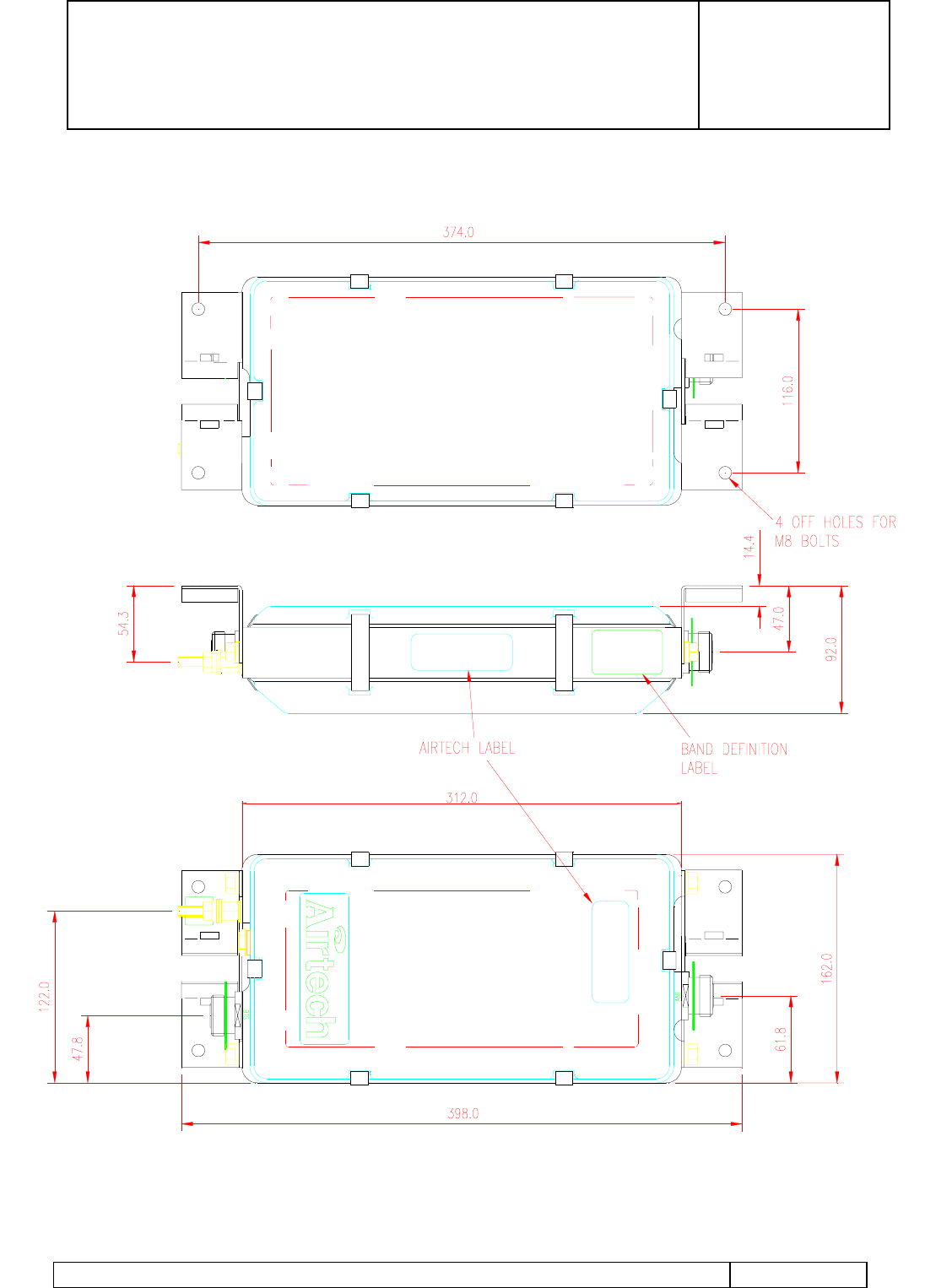
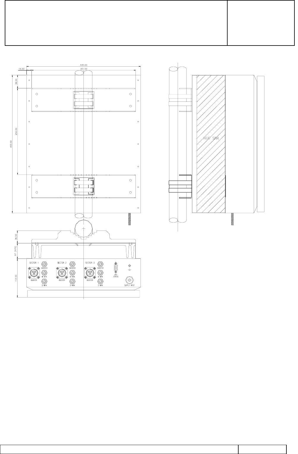
Figure 7 Interface Drawing for the PDU with Wall Mounted Bracket
INSTALLATION AND OPERATING
MANUAL
98/OSM/0019
ISSUE 1
13/04/99
Airtech DCS1800 / PCS1900 Booster System Installation and Operating Manual Page 18 of 25
Figure 8 Interface Drawing for the PDU with Pole Mounted Bracket

INSTALLATION AND OPERATING
MANUAL
98/OSM/0019
ISSUE 1
13/04/99
Airtech DCS1800 / PCS1900 Booster System Installation and Operating Manual Page 19 of 25
4. Installation of the Booster System
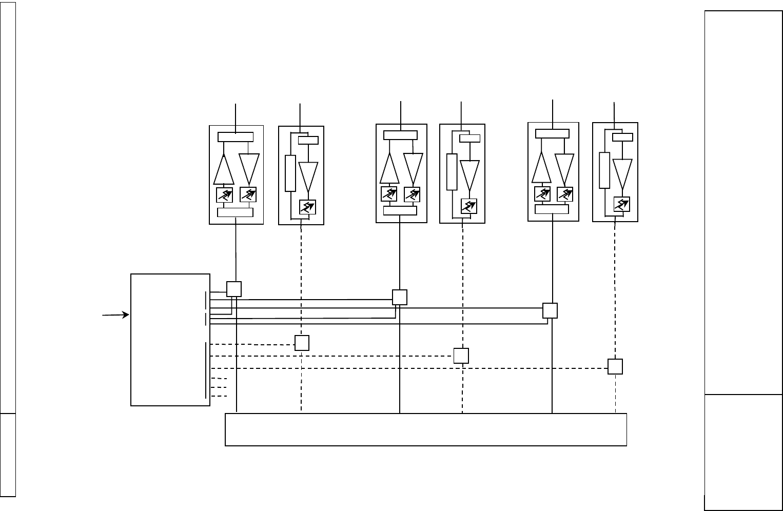
The Booster System connectivity for three sector configuration is shown in Figure 9. Each
sector consists of one Booster for main transmit and receive signals and one Masthead
Amplifier for diversity receive signal. The diversity MHA shown in the diagram is a
standard variable high gain dual duplexed MHA. The transmit section of the MHA when
used in the diversity path is not used. Some systems may have two diversity MHAs for
each sector (total of six for a three sector site). The PDU shown in the diagram has a
capability of providing power to three Boosters and six MHAs although connections to
only three MHAs are shown in the diagram.
CAUTION:
PRIOR TO INSTALLING THE BOOSTER SYSTEM OR
ANY OF ITS COMPONENTS, ENSURE THAT THE BTS
TRANSMITTER OUTPUT IS TURNED OFF AND THAT
PRECAUTIONS ARE TAKEN TO ENSURE THAT THE
TRANSMITTER CANNOT BE ACTIVATED DURING THE
EQUIPMENT INSTALLATION.
4.1 Booster
Prior to installing the booster assembly ensure that there is sufficient space available for
the mounting of the equipment to the mast pole or to the wall structure. This clearance
should include access for cable bend radius and termination of the feeder.
The booster is attached to the antenna pole by the use of two jaw clamp assemblies which
are fitted to the upper and lower mounting brackets.
The booster must be fitted vertically with the BTS feeder connector to the underside of the
equipment and the antenna port at the top. Only this arrangement will provide the correct
convection cooling required by the design.
Connect the booster Ground stud to the antenna Ground arrangement using a cable of at
least 24 mm2 cross-sectional area. The booster is connected to the cable using a 8 mm
grounding stud. Ensure that the torque applied to the booster ground stud nut does not
exceed 10 Nm.
Connect the BTS feeder jumper cable from the main feeder to the BTS port at the lower
end of the booster and the Antenna jumper cable to the upper end of the booster. Ensure
that the connectors are correctly mated then tighten the connector to 20 - 25 Nm using a
torque spanner. Ensure that the bend radii of the cable is not placing sideways stress on the
cable or connectors.

INSTALLATION AND OPERATING
MANUAL
98/OSM/0019
ISSUE 1
13/04/99
Airtech DCS1800 / PCS1900 Booster System Installation and Operating Manual Page 20 of 25
DO NOT CONNECT THE RF FEEDER CABLE FROM THE BTS
DIRECTLY TO THE BOOSTER. ALWAYS USE A JUMPER TO
PREVENT SIDELOADS ON THE CONNECTORS.
Once the connectors are correctly tightened onto to the Booster both of the cable ports
should be sealed using the heat-shrink sleeves.
Ensure that any excess cable is securely attached to the mast to prevent movement.
4.2 Booster Bias Tee
Ensure the BTS is turned off and all transmitters inhibited. Remove the antenna feeder
cables from the existing antenna output connectors (on top of the BTS cabinet) ensuring
that each cable assembly is identified with its mating location. Note: loosen the cable
support clamps where necessary to provide movement of cables
Attach a Booster Bias Tee assembly to each of the antenna outputs on the top of the BTS
cabinet and tighten each connector to 20 - 25 Nm using a torque spanner, whilst ensuring a
counter torque is applied to the connector body.
Connect each Bias Tee Ground stud to the cabinet primary Ground using a short length of
10 mm2 earth cable. This should be terminated in an M6 tag for connection to the Bias Tee
assembly, ensuring that the Ground stud nut is tightened to not greater than 4 Nm.
The external antenna feeder cables should be re-connected to the Booster Bias Tees,
ensuring that each antenna is connected to its original BTS output port, and tightened to 20
- 25 Nm torque, whilst ensuring a counter torque is applied to the connector body.
Retighten the cable support clamps where necessary to secure the cables
4.3 Masthead Amplifier
Prior to installing the MHA assembly ensure that there is sufficient space available for the
mounting of the equipment to the mast pole or to the wall structure. This clearance should
include access for cable bend radius and termination of the feeder.
The MHA is attached to the antenna pole by the use of the two adjustable strap assemblies
which are fitted to the upper and lower mounting brackets. Thread each of the strap
assemblies through the two slots provided in the mounting brackets. Wrap the straps
around the mounting pole and locate into the worm drive screw assembly. The two screw
assemblies should then be adjusted using a 8 mm open ended spanner or socket assembly,
ensuring that the torque applied to the screw does not exceed 2 Nm.
The MHA should be fitted vertically with the BTS feeder connector to the underside of the
equipment and the antenna port at the top.

INSTALLATION AND OPERATING
MANUAL
98/OSM/0019
ISSUE 1
13/04/99
Airtech DCS1800 / PCS1900 Booster System Installation and Operating Manual Page 21 of 25
Connect the MHA Ground stud to the antenna Ground arrangement using a cable of at
least 24 mm2 cross-sectional area. The MHA is connected to the cable using a 8 mm
grounding stud. Ensure that the torque applied to the MHA ground stud nut does not
exceed 10 Nm.
Connect the jumper from the output connector of the antenna to the port labeled ANT on
the top of the MHA. Ensure that the connectors are correctly mated then tighten the
connector to 20 - 25 Nm using a torque spanner. Ensure that the bend radii of the cable is
not placing sideways stress on the cable or connectors.
Connect the BTS feeder jumper cable from the main feeder to the BTS port at the lower
end of the MHA. Ensure that the connectors are correctly mated then tighten the connector
to 20 - 25 Nm using a torque spanner. Ensure that the bend radii of the cable is not placing
sideways stress on the cable or connectors.
DO NOT CONNECT THE RF FEEDER CABLE FROM THE BTS
DIRECTLY TO THE MHA. ALWAYS USE A JUMPER TO
PREVENT SIDELOADS ON THE CONNECTORS.
Once the connectors are correctly tightened onto to the MHA both of the cable ports
should be sealed using the heat-shrink sleeves.
Ensure that any excess cable is securely attached to the mast to prevent movement.
4.4 G3 MHA Bias Tee
Ensure the BTS is turned off and all transmitters inhibited. Remove the antenna feeder
cables from the existing antenna output connectors (on top of the BTS cabinet) ensuring
that each cable assembly is identified with its mating location. Note: loosen the cable
support clamps where necessary to provide movement of cables
Attach a Variable Gain MHA Bias Tee assembly to each of the antenna outputs on the top
of the BTS cabinet and tighten each connector to 20 - 25 Nm using a torque spanner,
whilst ensuring a counter torque is applied to the connector body.
Connect each Bias Tee Ground stud to the cabinet primary Ground using a short length of
10 mm2 earth cable. This should be terminated in an M6 tag for connection to the Bias Tee
assembly, ensuring that the Ground stud nut is tightened to not greater than 4 Nm.
The external antenna feeder cables should be re-connected to the Bias Tees, ensuring that
each antenna is connected to its original BTS output port, and tightened to 20 - 25 Nm
torque, whilst ensuring a counter torque is applied to the connector body. Retighten the
cable support clamps where necessary to secure the cables

INSTALLATION AND OPERATING
MANUAL
98/OSM/0019
ISSUE 1
13/04/99
Airtech DCS1800 / PCS1900 Booster System Installation and Operating Manual Page 22 of 25
4.5 Power Distribution Unit
Locate a suitable position for the installation of the PDU. Ensure that there is adequate air
flow around the heatsink.
Install the PDU using the supplied brackets mounting the unit vertically with the
connectors at the bottom.
Connect the PDU Ground stud to the primary Ground using a short length of 10 mm2 earth
cable. This should be terminated in an M8 tag for connection to the PDU assembly,
ensuring that the Ground stud nut is tightened to not greater than 10 Nm.
4.6 Electrical Installation
1. Ensure that the PDU circuit supply breaker is turned off at the distribution board.
Connect the PDU input cable from the distribution board to the PDU supply input.
Ensure that the connector is securely mated.
2. Connect the Booster DC Output cables between the PDU and the Booster Bias Tee.
3. Fit the Booster Communication cables between the PDU and the Booster Bias Tee.
4. Fit the MHA Cables between the PDU and the Variable Gain G3 compatible Bias Tee.
5. Connect the Alarm cable if required.
Note: Only use cable assemblies supplies by Airtech.
INSTALLATION AND OPERATING
MANUAL
98/OSM/0019
ISSUE 1
13/04/99
Airtech DCS1800 / PCS1900 Booster System Installation and Operating Manual Page 23 of 25
Figure 9 Booster System Connectivity
85 - 264
VAC
Tx/Rx Rx
SFSA
BOOSTER
Tx/Rx Rx
BT
BT
BT
BT
RF RF RF RF
Tx/Rx Rx
BT
BT
RF RF
SFSA
BOOSTER
MHA
(High Gain)
SFSA
BOOSTER
BOOSTER
PDU
MHA
(High Gain)
BTS
MAIN DIVERSITY MAIN DIVERSITY MAIN DIVERSITY
+30VDC
COMMS
+12VDC
and
COMMS
MHA
(High Gain)
BOOSTER SYSTEM CONNECTIVITY

INSTALLATION AND OPERATING
MANUAL
98/OSM/0019
ISSUE 1
13/04/99
Airtech DCS1800 / PCS1900 Booster System Installation and Operating Manual Page 24 of 25
5. Commissioning
5.1 Switch On
Ensure that the circuit breakers inside the Booster PDU are in the open position. Ensure
that the BTS transmitter output is turned off. Enable the supply to the PDU at the BBU
distribution board.
Enable the sector 1 circuit breaker within the Booster PDU. All the status LEDs for the
installed equipment on sector 1 should be green. If this is not the case check that
everything has been connected properly. If there are no obvious causes contact Airtech for
technical support.
Enable sector 2 and sector 3. Ensure that all the appropriate LEDs are green.
5.2 Status
LED
Label Description Conditions
COMMs Booster communication link Green = Good
COMMs Red = Fail
POWER PDU Power Green = Good
Red = Fail
VSWR Booster Output VSWR Green = Good
Red = Fail
Off = Booster Comms Failure/Booster not fitted
CURRENT Booster under current Green = Good
Red = Fail
Off = Booster Comms Failure/Booster not fitted
VOLTAGE Booster under voltage Green = Good
Red = Fail
Off = Booster Comms Failure/Booster not fitted
NOT USED
HPA TEMP Booster HPA Over Temperature Green = Good
Red = Fail
Off = Booster Comms Failure/Booster not fitted
M-MHA
SOFT FAIL M-MHA soft fail Green = Good
Red = Fail
Off = M-MHA Comms Failure/MHA not fitted
M-MHA
HARD FAIL M-MHA hard fail Green = Good
Red = Fail
Off = M-MHA Comms Failure/MHA not fitted
D-MHA
SOFT FAIL D-MHA soft fail Green = Good
Red = Fail
Off = D-MHA Comms Failure/MHA not fitted
D-MHA
HARD FAIL D-MHA hard fail Green = Good
Red = Fail
Off = D-MHA Comms Failure/MHA not fitted

INSTALLATION AND OPERATING
MANUAL
98/OSM/0019
ISSUE 1
13/04/99
Airtech DCS1800 / PCS1900 Booster System Installation and Operating Manual Page 25 of 25
5.3 Attenuator Settings
The HPA attenuator switch sets the transmit gain. The gain will be a maximum 12dB at
the “0” switch setting. The switches cover an attenuation range of 16dB ( 0 to F in
hexadecimal ) in 1dB steps.
The LNA attenuator sets the receive gain in the booster and the MHAs with a maximum of
22dB at the “0” switch setting. The switches cover an attenuation range of 16dB ( 0 to F in
hexadecimal ) in 1dB steps.
The voltage adjust switch is no longer required and has been disabled.
The transmit amplifier provides a maximum RF output power level of 20 watts (+43dBm)
and a nominal maximum gain of 12dB. It is essential that the gain of the booster is
adjusted to ensure that the output power does not exceed this level. The following
procedure may be used to this end.
1. Set the booster transmit attenuation to 15dB by setting the rotary switch on the control
panel to F.
2. Enable the BTS Tx carrier output at the required operating power level.
3. Whilst monitoring the booster output power using a suitable power meter gradually
decrease the Tx attenuation until the booster output power reaches the required level
(not exceeding 20W).
The booster system is now ready for performance testing.