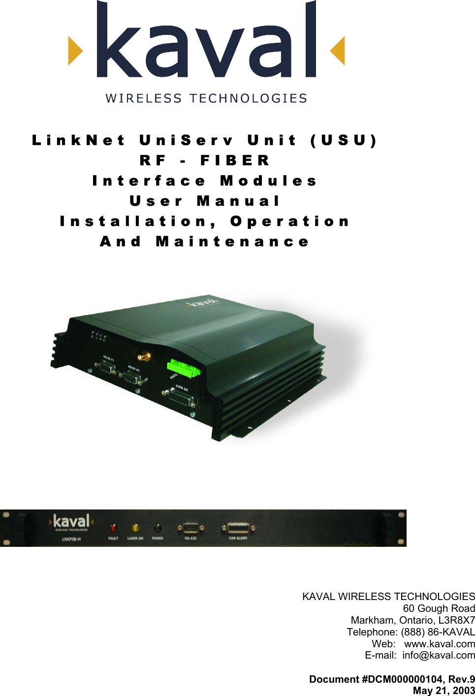
Powerwave Technologies US900P RF Fiber Interface Module, Model US900P User Manual USU1900P Manual Rev9
Powerwave Technologies Inc. RF Fiber Interface Module, Model US900P USU1900P Manual Rev9
Contents
- 1. Users Manual
- 2. Updated Users Manual
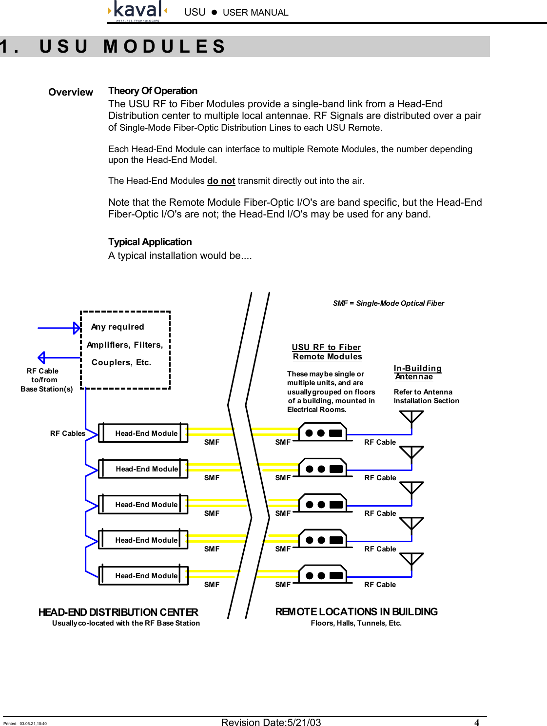
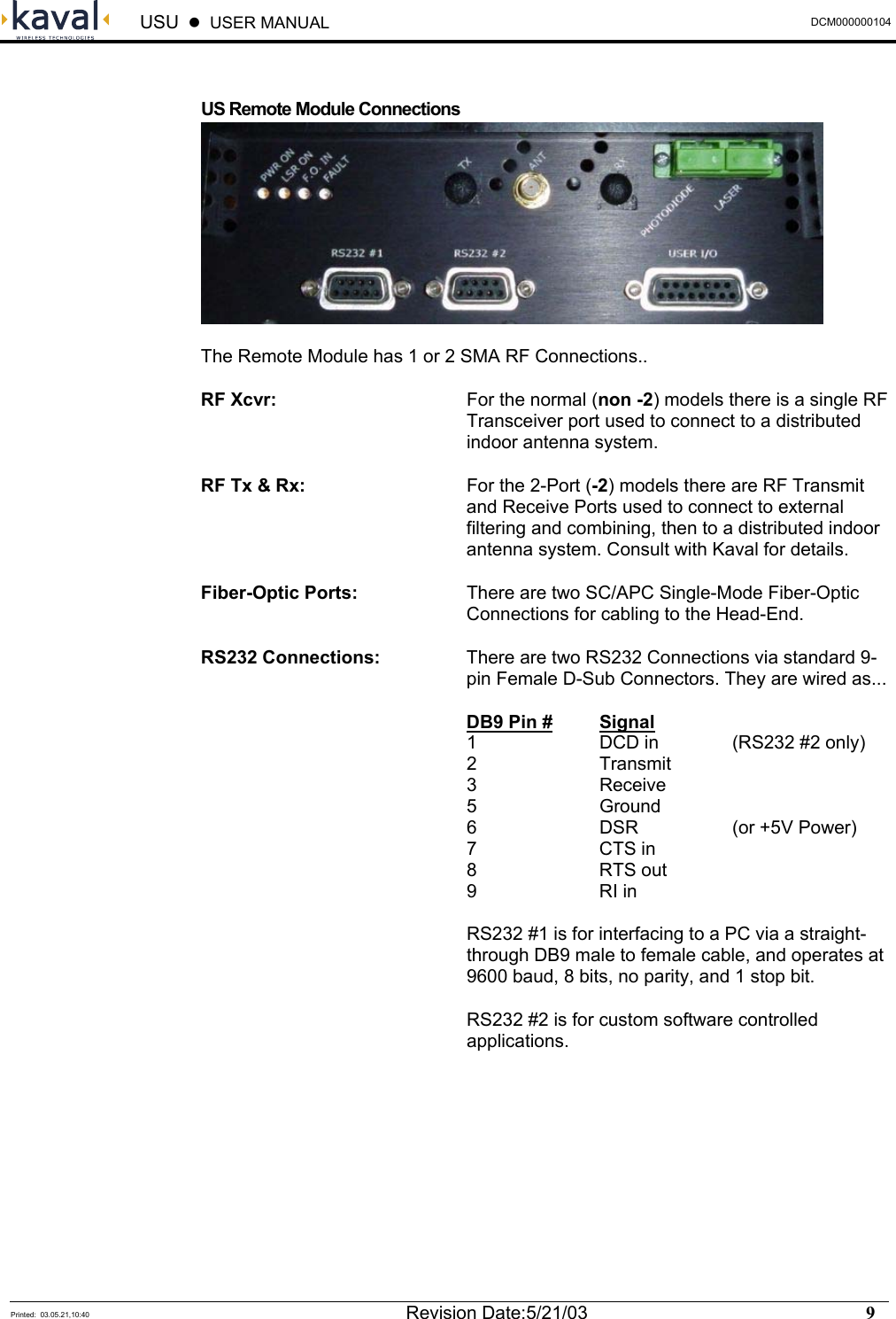
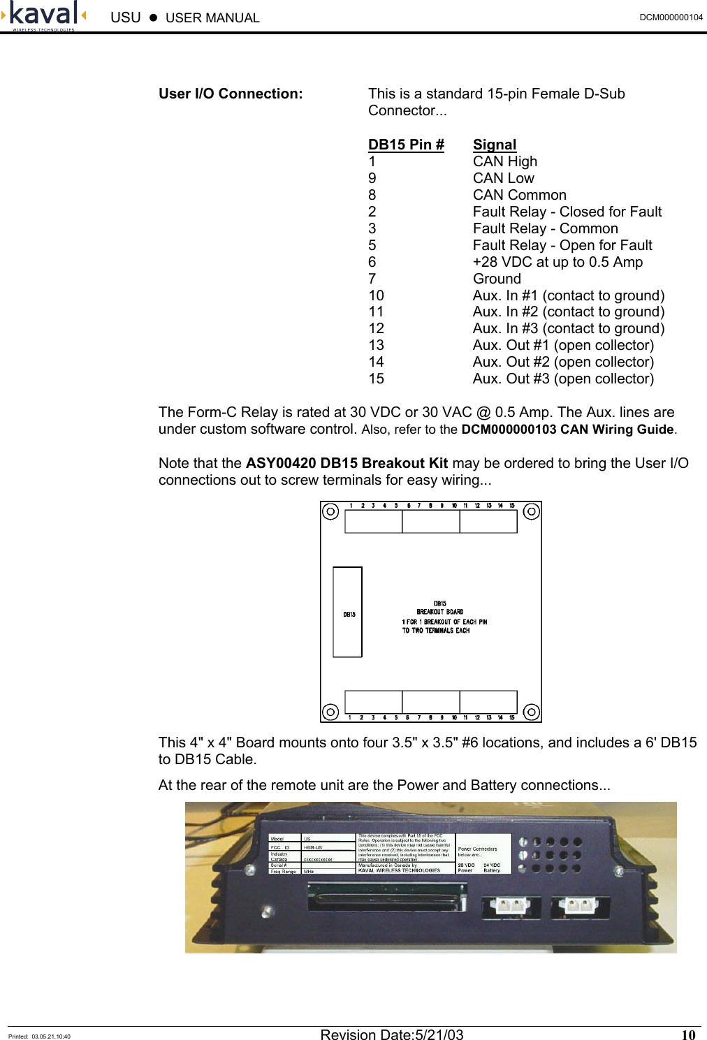
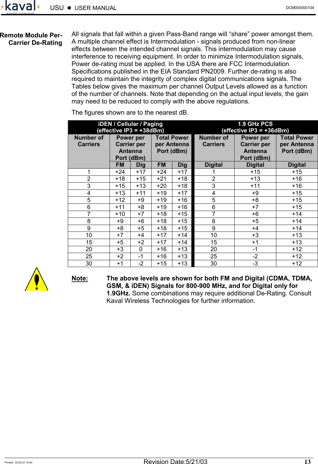
Users Manual