Powerwave Technologies US900P RF Fiber Interface Module, Model US900P User Manual USU1900P Manual Rev9
Powerwave Technologies Inc. RF Fiber Interface Module, Model US900P USU1900P Manual Rev9
Contents
- 1. Users Manual
- 2. Updated Users Manual
Users Manual
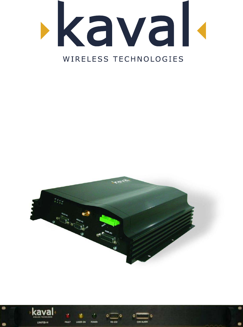
LinkNet UniServ Unit (USU)
RF - FIBER
Interface Modules
User Manual
Installation, Operation
And Maintenance
KAVAL WIRELESS TECHNOLOGIES
60 Gough Road
Markham, Ontario, L3R8X7
Telephone: (888) 86-KAVAL
Web: www.kaval.com
E-mail: info@kaval.com
Document #DCM000000104, Rev.9
May 21, 2003

USU USER MANUAL DCM000000104
Printed: 2003-05-21 10:40:07
Revision Date: 5/21/03: ii
P
PR
RO
OP
PR
RI
IE
ET
TA
AR
RY
Y
S
ST
TA
AT
TE
EM
ME
EN
NT
T
© 2000 KAVAL WIRELESS TECHNOLOGIES All rights reserved.
No part of this publication, or any software included with it may be reproduced, stored in a retrieval system,
or transmitted in any form or by any means, including photocopying, electronic, mechanical, recording or
otherwise, without the prior written permission of the copyright holder.
This document contains proprietary information of KAVAL WIRELESS TECHNOLOGIES The contents are
confidential and any disclosure to persons other than the officers, employees, agents or subcontractors of
the owner or licensee of this document, without the prior written consent of KAVAL WIRELESS
TECHNOLOGIES, is strictly prohibited.
KAVAL WIRELESS TECHNOLOGIES provides this document as is, without any warranty of any kind either
expressed or implied including, but not limited to, the implied warranties of merchantability and fitness of a
particular purpose. KAVAL WIRELESS TECHNOLOGIES may make changes or improvements in the
equipment, software, or specifications described in this document at any time and without notice. These
changes will be incorporated in new releases of this document.
This document may contain technical inaccuracies or typographical errors. KAVAL WIRELESS
TECHNOLOGIES waives responsibility for any labour, materials, or costs incurred by any person or party as
a result of using this document. KAVAL WIRELESS TECHNOLOGIES, and any of its affiliates shall not be
liable for any damages (including, but not limited to, consequential, indirect or incidental, special damages or
loss of profits or date) even if they were foreseeable and KAVAL WIRELESS TECHNOLOGIES has been
informed of their potential occurrence, arising out of or in connection with this document or its use.
T
TR
RA
AD
DE
E
M
MA
AR
RK
K
N
NO
OT
TI
IC
CE
E
This manual makes reference to trademarks that are the property of other companies. References are used
only to refer to the products or services of the trademark owners.
USU is a trademark of KAVAL WIRELESS TECHNOLOGIES

USU USER MANUAL DCM000000104
Printed: 2003-05-21 10:40:07
Revision Date: 5/21/03: iii
TABLE OF
CONTENTS
1. USU MODULES........................................ 4
OVERVIEW ............................................................. 4
Theory Of Operation......................................... 4
Typical Application............................................ 4
MODELS................................................................. 5
BLOCK DIAGRAMS .................................................. 6
LNKFIB-H03 and LNKFIB-H04 Head-End
Modules ............................................................ 6
US Remote Modules ........................................ 7
CONNECTIONS ....................................................... 8
LNKFIB-H03 and LNKFIB-H04 Head-End
Module Connections......................................... 8
US Remote Module Connections ..................... 9
HEAD-END TO REMOTE INTERCONNECTS............... 11
FIBER-OPTIC CONNECTIONS ................................. 11
POWER FOR THE .................................................. 11
REMOTE MODULE................................................. 11
BATTERY BACKUP OF REMOTE MODULE ................ 11
MODULE SPECIFICATIONS ..................................... 12
REMOTE MODULE PER-CARRIER DE-RATING......... 13
OPERATION .......................................................... 14
Normal Operation ........................................... 14
Fault Indications ............................................. 14
Configuration and PC Commands.................. 15
GAIN ADJUSTMENTS ............................................. 16
SIGNAL LEVEL ADJUSTMENTS ............................... 16
PRODUCT WARRANTY........................................... 17
RMA PROCEDURE ............................................... 17
LASER SAFETY ..................................................... 18
ANTENNA INSTALLATION........................................ 19
FCC INFORMATION TO USERS .............................. 19
USU USER MANUAL
Printed: 03.05.21,10:40
Revision Date:5/21/03 4
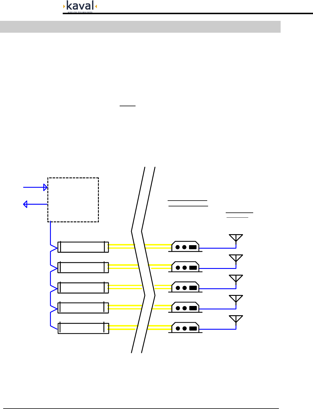
Theory Of Operation
The USU RF to Fiber Modules provide a single-band link from a Head-End
Distribution center to multiple local antennae. RF Signals are distributed over a pair
of Single-Mode Fiber-Optic Distribution Lines to each USU Remote.
Each Head-End Module can interface to multiple Remote Modules, the number depending
upon the Head-End Model.
The Head-End Modules do not transmit directly out into the air.
Note that the Remote Module Fiber-Optic I/O's are band specific, but the Head-End
Fiber-Optic I/O's are not; the Head-End I/O's may be used for any band.
Typical Application
A typical installation would be....
1. USU MODULES
Overview
USU RF to Fiber
Remote Modules
These may be single or
multiple units, and are
usually grouped on floors
of a building, mounted in
Elect rical Rooms.
In-Building
Antennae
Refer to Antenna
Installation Section
Head-End Module
Head-End Module
Head-End Module
Head-End Module
Head-End Module
HEAD-END DISTRIBUTION CENTER REMOTE LOCATIONS IN BUILDING
Usually co-located with the RF Base Station Floors, Halls, Tunnels, Etc.
Any required
Amplifiers, Filters,
Couplers, Etc.
RF Cable
RF Cable
RF Cable
RF Cable
RF Cable
RF Cables
RF Cable
to/from
Base Stat ion(s)
SMF = Single-Mode Optical Fiber
SMF
SMF
SMF
SMF
SMF
SMF
SMF
SMF
SMF
SMF
USU USER MANUAL DCM000000104
Printed: 03.05.21,10:40
Revision Date:5/21/03 5
MODEL DESCRIPTION
US800TP
USU Remote Module
Wall, Shelf, or Rack Mounted Remote Module that connects to the
Single-Mode Fiber-Optic Distribution Lines and provides a single
duplex Antenna RF Distribution connection. This model covers
800MHz Trunking / iDEN / Public-Safety Services
(806-824 MHz / 851-869 MHz).
US800C
USU Remote Module
As above, but this model covers 800MHz Cellular Services
(824-849 MHz / 869-894 MHz)
US900P
USU Remote Module
As above, but this model covers 900MHz Paging Services
(896-902 MHz / 928-941 MHz)
US1900P
USU Remote Module
As above, but this model covers 1.9GHz PCS Services
(1850-1910 MHz / 1930-1990 MHz).
Note that for each Model above there is a Model with a "-2" suffix. These extra models
have separate Rx and Tx RF Ports instead of a combined Transceiver (Antenna) Port.
US-PS01 Power Supply for 1 US Remote Module.
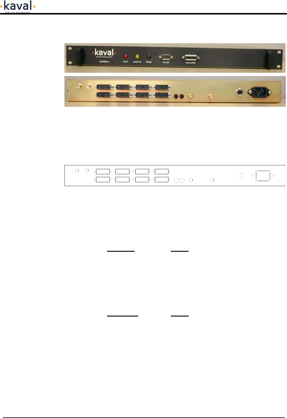
LNKFIB-H03
Head-End Module
This is a 1U high, 19" Rack-Mount Module providing low signal
level interfacing between Head-End RF Modules and 8 Pairs of
Single-Mode Fiber-Optic Distribution Lines. The 8 Fiber-Optic Pairs
are in two groups of four, with the RF connections combined inside
the Module in those groupings.
LNKFIB-H04
Head-End Module
This is a 1U high, 19" Rack-Mount Module providing low signal
level interfacing between Head-End RF Modules and 4 Pairs of
Single-Mode Fiber-Optic Distribution Lines. The RF connections for
the 4 Fiber-Optic Pairs are combined inside the Module.
Models
USU USER MANUAL DCM000000104
Printed: 03.05.21,10:40
Revision Date:5/21/03 6
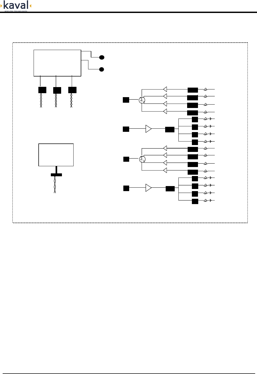
LNKFIB-H03 and LNKFIB-H04 Head-End Modules
In the LNKFIB-H03 Head-End Module the 8 Fiber-Optic Pairs are in two Banks (A & B)
of four, with the RF connections combined inside the Module in those groupings. The
LNKFIB-H04 is identical, but with one Bank of 4 removed.
Each of the Groups of four consists of a single RF Input feeding a single Laser
Transmitter split optically to four Fiber-Optic Outputs. The four matching Fiber-Optic
Inputs each go to their own Photodiode Receiver, followed by a 0 to -15dB digitally
controlled attenuator providing Uplink Gain Control. The RF signals from the four
digital attenuators are combined into a single RF Output.
The Group-of-Four RF Input and Output combining inside the Module alleviates the
need for external combining / splitting.
Block Diagrams
SM F.O. In
SM F.O. Out
(PI N Diodes)
(Lasers)
Power Supply
120 / 240 VAC
120/240 VAC
PreAmp
L aser Dio de
Photodetectors & PreAmps
RF O ut "A"
RF Input "A"
SM F.O. In
SM F.O. Out
(PI N Diodes)
(Lasers)
PreAmp
L aser Dio de
Photodetectors & PreAmps
RF O ut "A"
RF Input "A"
With UpLink Gain Control
With UpLink Gain Control
Micro-Controller
Circuitry
CAN Interface RS232 Interface
To Head-End To PC
Green P ower On LED
Red Fault LED
Fault Relay
USU USER MANUAL DCM000000104
Printed: 03.05.21,10:40
Revision Date:5/21/03 7
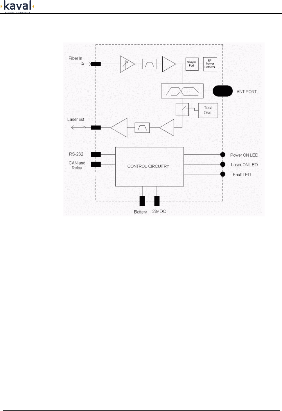
US Remote Modules
The US series Remote Modules have a Fiber-Optic transceiver pairs downlink and
uplink filtering, and an downlink RF Power Amplifier.
USU USER MANUAL DCM000000104
Printed: 03.05.21,10:40
Revision Date:5/21/03 8
LNKFIB-H03 and LNKFIB-H04 Head-End Module Connections
The LNKFIB-H03 Head-End has two Downlink RF Inputs providing the signal for
eight Downlink Optical Outputs arranged as groups of four, "A" and "B". It also has
eight Uplink Optical Inputs combined in two groups of four providing RF Outputs "A"
and "B". The RF and optical connections are all on the rear panel. The Group-of-
Four RF Input and Output combining inside the Module alleviates the need for
external combining / splitting.
RF OUT A B
Rx - A2 - Tx
Rx - A1 - Tx
Rx - A3 - Tx
Rx - A4 - Tx
Rx - B2 - Tx
Rx - B1 - Tx
Rx - B3 - Tx
Rx - B4 - Tx
ADDRESS
LOW HI A B RF INPUT
3 AMP
BREAKER
120 VAC
60 Hz
The CAN, RS232, and Fault Relay Interface connections are all on the front panel.
Their connections are...
RS232 Connection:
The RS232 Port is for interfacing to a PC via a Null-Modem DB9 female to
female cable, and operates at 9600 baud, 8 bits, no parity, and 1 stop bit. It
is a 3-wire connection with...
DB9 Pin # Signal
2 RS232 Receive
3 RS232 Transmit
5 Ground
User I/O Connection:
This Connection is via a standard 15-pin Female D-Sub Connector on the
side of the enclosure...
DB15 Pin # Signal
1 CAN High
9 CAN Low
8 CAN Common (Ground)
3 Fault Relay Common
2 Fault Relay - Closed for Fault
4 Fault Relay - Open for Fault
The Form-C Relay is rated at 30 VDC or 30 VAC @ 0.5 Amp.
Also, refer to the DCM000000103 CAN Wiring Guide.
Connections
USU USER MANUAL DCM000000104
Printed: 03.05.21,10:40
Revision Date:5/21/03 9
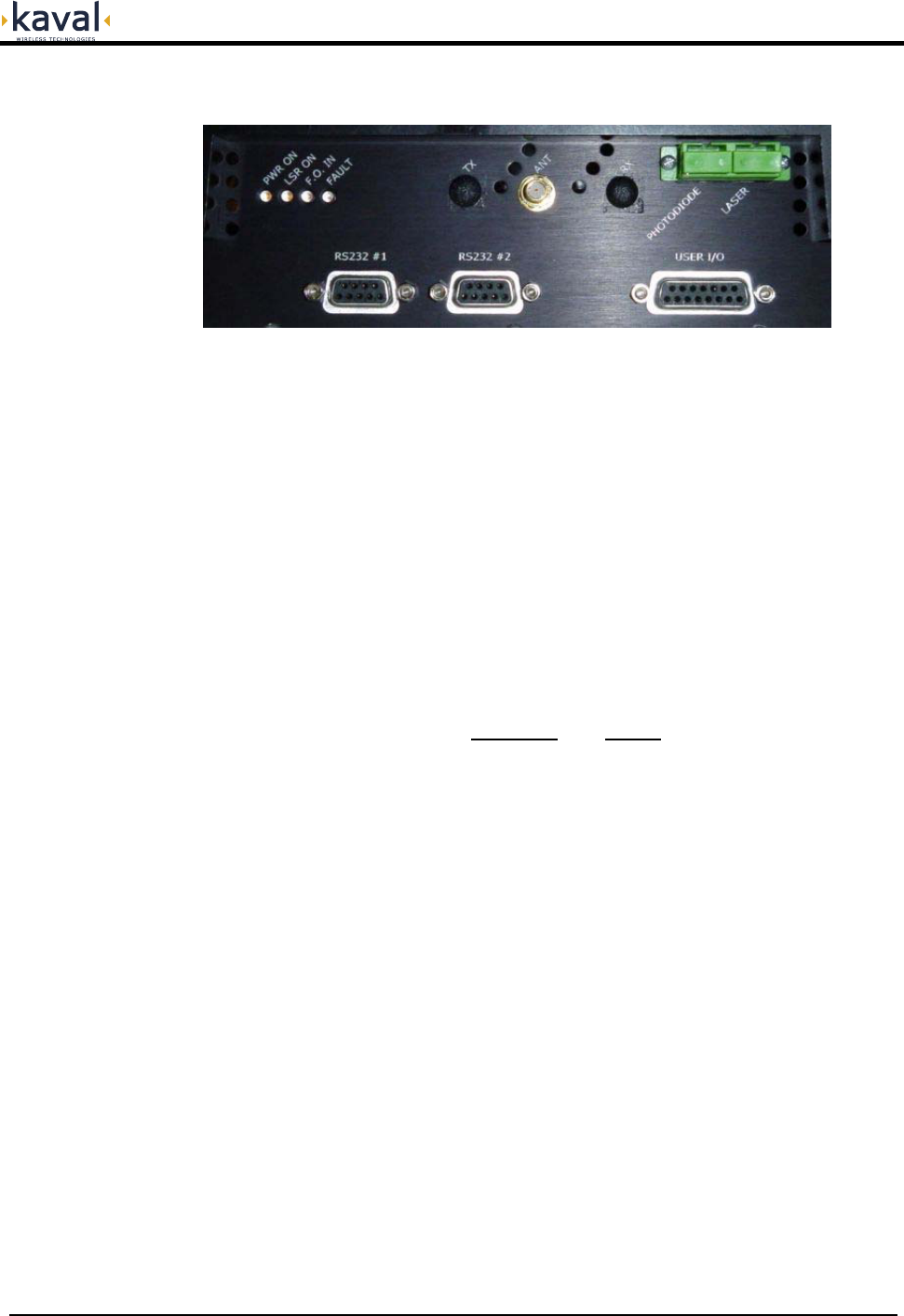
US Remote Module Connections
The Remote Module has 1 or 2 SMA RF Connections..
RF Xcvr: For the normal (non -2) models there is a single RF
Transceiver port used to connect to a distributed
indoor antenna system.
RF Tx & Rx: For the 2-Port (-2) models there are RF Transmit
and Receive Ports used to connect to external
filtering and combining, then to a distributed indoor
antenna system. Consult with Kaval for details.
Fiber-Optic Ports: There are two SC/APC Single-Mode Fiber-Optic
Connections for cabling to the Head-End.
RS232 Connections: There are two RS232 Connections via standard 9-
pin Female D-Sub Connectors. They are wired as...
DB9 Pin # Signal
1 DCD in (RS232 #2 only)
2 Transmit
3 Receive
5 Ground
6 DSR (or +5V Power)
7 CTS in
8 RTS out
9 RI in
RS232 #1 is for interfacing to a PC via a straight-
through DB9 male to female cable, and operates at
9600 baud, 8 bits, no parity, and 1 stop bit.
RS232 #2 is for custom software controlled
applications.
USU USER MANUAL DCM000000104
Printed: 03.05.21,10:40
Revision Date:5/21/03 10
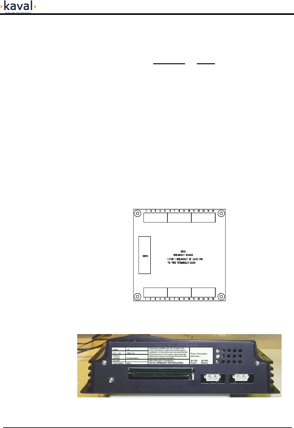
User I/O Connection: This is a standard 15-pin Female D-Sub
Connector...
DB15 Pin # Signal
1 CAN High
9 CAN Low
8 CAN Common
2 Fault Relay - Closed for Fault
3 Fault Relay - Common
5 Fault Relay - Open for Fault
6 +28 VDC at up to 0.5 Amp
7 Ground
10 Aux. In #1 (contact to ground)
11 Aux. In #2 (contact to ground)
12 Aux. In #3 (contact to ground)
13 Aux. Out #1 (open collector)
14 Aux. Out #2 (open collector)
15 Aux. Out #3 (open collector)
The Form-C Relay is rated at 30 VDC or 30 VAC @ 0.5 Amp. The Aux. lines are
under custom software control. Also, refer to the DCM000000103 CAN Wiring Guide.
Note that the ASY00420 DB15 Breakout Kit may be ordered to bring the User I/O
connections out to screw terminals for easy wiring...
This 4" x 4" Board mounts onto four 3.5" x 3.5" #6 locations, and includes a 6' DB15
to DB15 Cable.
At the rear of the remote unit are the Power and Battery connections...

USU USER MANUAL DCM000000104
Printed: 03.05.21,10:40
Revision Date:5/21/03 11
The Single-Mode Fiber-Optic interconnections between the Head-End and Remote
Modules are to be made in whatever manner suits the system configuration. For the
CAN Network connections please refer to DCM000000103.
All Fiber-Optic Cabling must use 9/125 or similar Single-Mode (yellow
jacketed) high-quality cable. This cable should typically have less than 0.5
dBo (optical dB) insertion loss per kilometer.
From the cable manufacturer's specification, minimum bend radius must
be observed.
Most Kaval products use SC/APC connectors. Note that the "APC" is
critical. These are angle-polished connectors and are required to reduce
reflections.
Fiber-Optic Patchcords should be avoided; Fusion-Splices are preferred to
reduce reflections.
Fiber-Optic Connectors, both on cables and equipment, should always
have their dust caps in place when not in use. The connector tips must be
kept clean and scratch free, and should always be cleaned properly before
being connected.
Optical Reflections back into laser diodes cause a disturbance in the
lasers gain cavity creating noise and distortion. An OTDR or other Fiber-
Optic Instruments should be used to check optical reflections. Fiber-Optic
Return Loss should be less than -50 dBo.
There is a 2 to 1 Relationship between optical loss and RF loss. One dBo
(optical dB) of optical loss corresponds to 2 dB of RF loss.
The US Remote Module may be powered by any source of negative ground
+28VDC power capable of delivering 1 Ampere. This includes the optional single US
Remote Module US-PS01 Power Supply...
If the USU Remote Module is being used without a Battery it must be configured to
NOT use a battery. Without a battery the USU will shut down or reset with any
disruption to the AC power. When power is re-established the system will restart
automatically. External batteries may be connected using the CAB000000055
Battery Cable. The USU has a built-in battery charger that will automatically
recharge the attached battery.
Refer to DCM000000102 "Battery Backup Manual".
For Battery Backup purposes...
Vbat = 24 VDC Ic = 0.1 Ampere Id = 0.75 Ampere
Head-End to Remote
Interconnects
Fiber-Optic
Connections
Power for the
Remote Module
Battery Backup of
Remote Module

USU USER MANUAL DCM000000104
Printed: 03.05.21,10:40
Revision Date:5/21/03 12
Frequency Bands Refer to Model Chart
Maximum Downlink Power
+38 dBm IP3 Minimum for iDEN, Cell, Page
+36 dBm IP3 Minimum for PCS
(see Remote Module Carrier De-Rating Chart)
Maximum Uplink Power
Combined at any Head-End RF Output.
Includes the 4-way combiner loss.
+4 dBm IP3 Minimum, iDEN/Cell/Page
0 dBm IP3 Minimum, PCS
(7 to 12dB higher for LNKFIB-H01)
Downlink Gain
from Head-End to the Remote Module
Antenna Port, assuming 0dB Fiber-Optic Link
+20 dB after Gain Adjustment
Typical range before Gain Adjust is
+20 to +35 dB for 800-900 MHz Bands
+20 to +31dB for 1.9 GHz Bands
(See Gain Adjustments)
Downlink Gain Ripple +/- 2.5 dB, iDEN, Cell, Page
+/- 3 dB, PCS
Uplink Gain
from Remote Module Antenna Port to Head-End,
assuming 0dB Fiber-Optic Link
+20 dB after Gain Adjustment
Typical range before Gain Adjust is
+20 to +32 dB for 800-900 MHz Bands
+20 to +32dB for 1.9 GHz Bands
(See Gain Adjustments)
Uplink Gain Ripple +/- 2.5 dB, iDEN, Cell, Page
+/- 3 dB, PCS
Max RF Input without Damage
To Head-End Units +10 dBm
Uplink Noise
at Head-End Unit from any Remote Module Antenna
Port assuming 0dB Fiber-Optic Link
< -130 dBm/Hz
(with Uplink Gains Balanced)
Isolation Consult Kaval Engineering Services
(depends upon Head-End Filtering)
Duty Cycle Continuous
Spurious Outputs -20 dBm max per Remote Module Antenna Port
when operated as per De-rating Chart
Optical Power Level
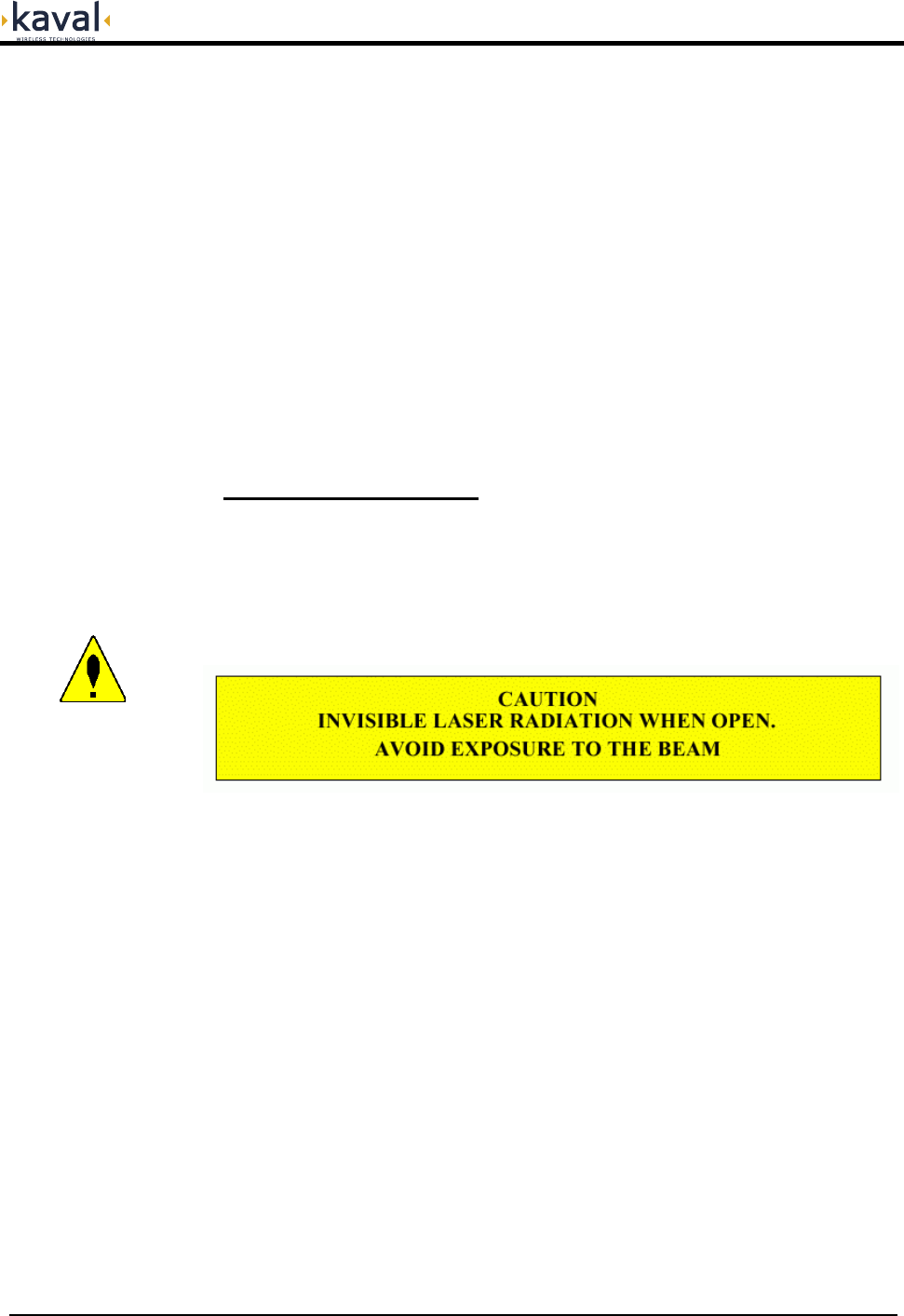
Laser Warning: Invisible Laser Radiation emitting
from optical connector. Avoid direct exposure to
beam. 150 mW max. @1300nm. Class IIIb. Product
complies with 21 CFR 1040.10 and 1040.11.
Optical Path Loss 2 dBO Maximum
Group Delay <2uS, NOT including Fiber-Optic Link
Connectors SC/APC Fiber-Optic, SMA (50ς) RF
D-Sub Data & Control
Head-End Module Power Supply Requirements 120 VAC, 50/60 Hz, 120 VA Typical, 200 VA Max.
Remote Module Power Supply Requirements
28 VDC from external Power Supply
0.75 Ampere Maximum
and 24VDC "Gell-Cell" Battery Backup Option
Configuration Options Either via the USU network and a Gateway Module,
or via a PC and an RS-232 Connection.
Operating Temperature Range -20 to +50oC
Operating Humidity Range 5 to 90% RH, Non-Condensing
Head-End Module Size & Weight 1U High 19” Rack Unit, 14" Deep, 16 lbs Max
Remote Module Size & Weight 2.75” High, 9.25” Wide, 11” Deep, 7 lbs Max
FCC Identifiers FCC: H6M-US800TP FCC: H6M-US800C
FCC: H6M-US900P FCC: H6M-US1900P
Industry Canada Certifications IC: 1541A-US800TP IC: 1541A-US800C
IC: 1541A-US900P IC: 1541A-US1900P
Module Specifications
USU USER MANUAL DCM000000104
Printed: 03.05.21,10:40
Revision Date:5/21/03 13
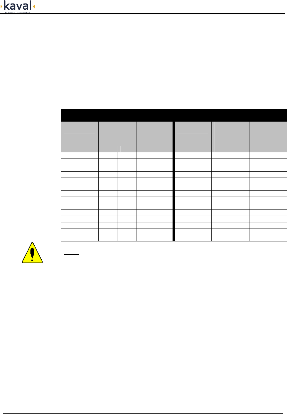
All signals that fall within a given Pass-Band range will “share” power amongst them.
A multiple channel effect is Intermodulation - signals produced from non-linear
effects between the intended channel signals. This intermodulation may cause
interference to receiving equipment. In order to minimize Intermodulation signals,
Power de-rating must be applied. In the USA there are FCC Intermodulation
Specifications published in the EIA Standard PN2009. Further de-rating is also
required to maintain the integrity of complex digital communications signals. The
Tables below gives the maximum per channel Output Levels allowed as a function
of the number of channels. Note that depending on the actual input levels, the gain
may need to be reduced to comply with the above regulations.
The figures shown are to the nearest dB.
iDEN / Cellular / Paging
(effective IP3 = +38dBm)
1.9 GHz PCS
(effective IP3 = +36dBm)
Power per
Carrier per
Antenna
Port (dBm)
Total Power
per Antenna
Port (dBm)
Number of
Carriers
Power per
Carrier per
Antenna
Port (dBm)
Total Power
per Antenna
Port (dBm)
Number of
Carriers
FM Dig FM Dig Digital Digital Digital
1 +24 +17 +24 +17 1 +15 +15
2 +18 +15 +21 +18 2 +13 +16
3 +15 +13 +20 +18 3 +11 +16
4 +13 +11 +19 +17 4 +9 +15
5 +12 +9 +19 +16 5 +8 +15
6 +11 +8 +19 +16 6 +7 +15
7 +10 +7 +18 +15 7 +6 +14
8 +9 +6 +18 +15 8 +5 +14
9 +8 +5 +18 +15 9 +4 +14
10 +7 +4 +17 +14 10 +3 +13
15 +5 +2 +17 +14 15 +1 +13
20 +3 0 +16 +13 20 -1 +12
25 +2 -1 +16 +13 25 -2 +12
30 +1 -2 +15 +13 30 -3 +12
Note: The above levels are shown for both FM and Digital (CDMA, TDMA,
GSM, & iDEN) Signals for 800-900 MHz, and for Digital only for
1.9GHz. Some combinations may require additional De-Rating. Consult
Kaval Wireless Technologies for further information.
Remote Module Per-
Carrier De-Rating
USU USER MANUAL DCM000000104
Printed: 03.05.21,10:40
Revision Date:5/21/03 14
Normal Operation
For both USU Head-End and Remote Modules ...
POWER / OPERATING - This LED will be GREEN when the Module is
operating.
LASER - This LED will light GREEN when any one of the Lasers are
operating.
F.O. Input - (Remote only) This LED will light GREEN when an Optical
Signal is received.
FAULT - If the internal diagnostics detect a problem, then this LED will light
Red.
Fault Indications
Each Module continuously performs internal diagnostics. If a problem is detected it
will activate its Red Fault LED and Fault Relay. Faults detected include...
• Over Temperature
• Misc. Internal Faults
Detailed Faults are detected by the optional Gateway Module. Details may also be
determined via an RS232 connected Terminal Emulator using the LIST command.
Operation

USU USER MANUAL DCM000000104
Printed: 03.05.21,10:40
Revision Date:5/21/03 15
Configuration and PC Commands
It is possible to re-configure Modules in the field, either with a Personal Computer
(PC) or via the optional LinkNet Gateway Module. To use a PC it is necessary to
connect the DB9 RS-232 connector on the Module to a standard DB9 RS232
Connector on the PC. On the PC a terminal emulation program such as
HyperTerminal is used to communicate to the LinkNet Module. The settings are
9600 baud, 8 bits, no parity, and 1 stop bit. Commands are one or two words
followed by pressing Return. Commands may be given in upper or lower-case.
Available commands are...
Head-End Modules:
ACCESS USER: Required as a simple password to gain access to customer
settable parameters and diagnostics; This will time-out after 10
minutes, and may have to be re-typed.
HELP or ?: Displays a list of Available Commands.
LIST: Displays Current Settings and Status Faults, Etc.
VER: Display the current Version of Software.
ENABLE 1 or 0: Enables or Disables the Module.
DIGATTN x yyy: Displays or Sets the Uplink Gain Reduction yyy, which is in tenths
of a dB. The Optical to RF Path being set is x, which is...
x = 0 is for Uplink Optical to RF Path A1
x = 1 is for Uplink Optical to RF Path A2
x = 2 is for Uplink Optical to RF Path A3
x = 3 is for Uplink Optical to RF Path A4
x = 4 is for Uplink Optical to RF Path B1
x = 5 is for Uplink Optical to RF Path B2
x = 6 is for Uplink Optical to RF Path B3
x = 7 is for Uplink Optical to RF Path B4
Remote Modules:
ACCESS USER: Required as a simple password to gain access to customer
settable parameters and diagnostics; This will time-out after 10
minutes, and may have to be re-typed.
HELP or ?: Displays a list of Available Commands.
LIST: Displays Current Settings and Status Faults, Etc.
VER: Display the current Version of Software.
ENABLE 1 or 0: Enables or Disables the Module.
DIGATTN ###: Displays or Sets the Downlink Gain Reduction, which is in tenths
of a dB
Please consult Kaval Wireless Technologies for further support.

USU USER MANUAL DCM000000104
Printed: 03.05.21,10:40
Revision Date:5/21/03 16
Gain Adjustment is necessary to compensate for the variations in the Fiber-Optic
components of the Head-End and Remote Modules. This must be done after
Modules are deployed in a System, and anytime a Module is replaced. The
adjustments are on an individual RF Path basis, and each path is adjustable
downwards in 1dB steps up to -15dB.
It is recommended that these adjustments be performed with the aid of a Signal
Generator and Spectrum Analyzer.
Uplink Gain:
The Uplink Gain is adjusted at the Head-End Module on an individual RF path basis.
Please refer to the Head-End DIGATTN Commands in the Configuration and PC
Commands section. All DIGATTN Values are set to 0 (Maximum RF Gain). While
monitoring the RF gain via measurements, the individual gain paths are adjusted
downwards with the DIGATTN command to meet the Specified Gain. This will
optimize / balance both gain and noise.
Downlink Gain:
The Downlink Gain is adjusted at the Remote Module an individual RF path basis.
Please refer to the Remote DIGATTN Commands in the Configuration and PC
Commands section. All DIGATTN Values are set to 0 (Maximum RF Gain). While
monitoring the RF gain via measurements, the individual gain paths are adjusted
downwards with the DIGATTN command to meet the Specified Gain. This will
optimize / balance both gain and noise.
Signal Level Adjustment is necessary to ensure that the Downlink RF Carriers
transmitted via the Remote Modules are not generating undesired intermodulation
products, nor are they being distorted beyond use. Refer to the earlier section on
Remote Module Per-Carrier De-Rating.
It is recommended that these adjustments be performed with the aid of a Signal
Generator and Spectrum Analyzer, and that they be done AFTER the Gain
Adjustments.
Adjust the Downlink Interface Amplifiers and/or attenuators between the Base
Station (see the Typical Application drawing) to achieve the specified de-rated per-
carrier level.
Uplink Signals should be monitored as they feed into the Base Station - this is
usually a site specific requirement.
Gain Adjustments
Signal Level
Adjustments

USU USER MANUAL DCM000000104
Printed: 03.05.21,10:40
Revision Date:5/21/03 17
Please contact Kaval Wireless Technologies for a copy of the Standard Product
Warranty.
All returns, including warranty returns, must have a valid Return Material
Authorization (RMA) number.
Customers must contact KAVAL WIRELESS TECHNOLOGIES before shipping any
product for warranty service and obtain a Returned Materials Authorization and
detailed shipping instructions. Shipping charges, for shipment of product to KAVAL
WIRELESS TECHNOLOGIES for warranty service, will be borne by KAVAL
WIRELESS TECHNOLOGIES if a defect covered by warranty is found and warranty
service is required. At KAVAL WIRELESS TECHNOLOGIES’s sole discretion, a
service fee will be charged if a returned unit is found by KAVAL WIRELESS
TECHNOLOGIES not to be defective, or defective for a reason that voids this
warranty. Return shipping charges shall, in such case, be the responsibility of the
customer.
Product Warranty
RMA Procedure
USU USER MANUAL DCM000000104
Printed: 03.05.21,10:40
Revision Date:5/21/03 18
• CAUTION – use of controls or adjustments, or performance of
procedures other than those specified herein may result in
hazardous radiation exposure.
• This laser product is certified as a CLASS I laser product to the
requirements of the US Federal Product Performance Standard for Laser
Products contained in the regulations in 21 CFR Subchapter J. Class I
laser products are not considered to be hazardous.
• This laser product incorporates a Class IIIb laser module, which generates
levels of invisible laser radiation that may be hazardous. However, this
machine incorporates protective housing and optical fibers in the machine
design such that there is no exposure or human access to laser radiation
when the product is properly installed.
• All optical output connections to the LinkNet UniServ Unit (USU) must either
have an optical fiber connected or be capped.
• UNDER NO CIRCUMSTANCE shall attempts be made to operate this system
without the optical fibers connected or with caps removed from the optical
output connectors.
• All service to the LinkNet UniServ Unit (USU) shall be performed by Kaval
Wireless Technologies service personnel, their authorized agents, or
personnel trained by Kaval Wireless Technologies.
Laser Safety
USU USER MANUAL DCM000000104
Printed: 03.05.21,10:40
Revision Date:5/21/03 19
• All Antenna Installation to be performed by Qualified Technical Personnel only.
• Antenna Installation Instructions and locations below are for the purpose of
satisfying FCC RF Exposure Compliance requirements.
• The In-Building Antenna connection is via a coaxial cable distribution system
with Signal Taps at various points connected to the fixed-mounted Indoor
Antennae. This is shown in the figure in the Introduction. The Indoor Antennae
are simple 1/4 Wavelength (0 dB Gain) types. Please consult Kaval Wireless for
assistance as required. These Antennae are to be installed such that no person
can touch the Antenna, or approach within 0.2 Meters.
ANTENNA INSTALLATION
WARNING
ALL ANTENNA INSTALLATION IS TO BE PERFORMED BY QUALIFIED
TECHNICAL PERSONNEL ONLY.
ANTENNA INSTALLATION INSTRUCTIONS AND LOCATIONS ARE FOR THE
PURPOSE OF SATISFYING FCC RF EXPOSURE COMPLIANCE
REQUIREMENTS, AND ARE NOT OPTIONAL.
ALL IN-BUILDING ANTENNAE INSTALLATIONS MUST BE SUCH THAT NO
PERSON CAN TOUCH THE ANTENNAE, OR APPROACH CLOSER THAN 0.2
METERS.
• This equipment has been tested and found to comply with the limits for a Class
A digital device, pursuant to Part 15 of the FCC Rules. These limits are
designed to provided reasonable protection against harmful interference when
the equipment is operated in a commercial environment. This equipment
generates, uses, and can radiate radio frequency energy and, if not installed and
used in accordance with the instruction manual, may cause harmful interference
to radio communications. Operation of this equipment in a residential area is
likely to cause harmful interference in which case the user will be required to
correct the interference at his own expense.
WARNING
CHANGES OR MODIFICATIONS NOT EXPRESSLY APPROVED BY KAVAL
COULD VOID THE USER’S AUTHORITY TO OPERATE THE EQUIPMENT.
Antenna Installation
FCC Information to
Users