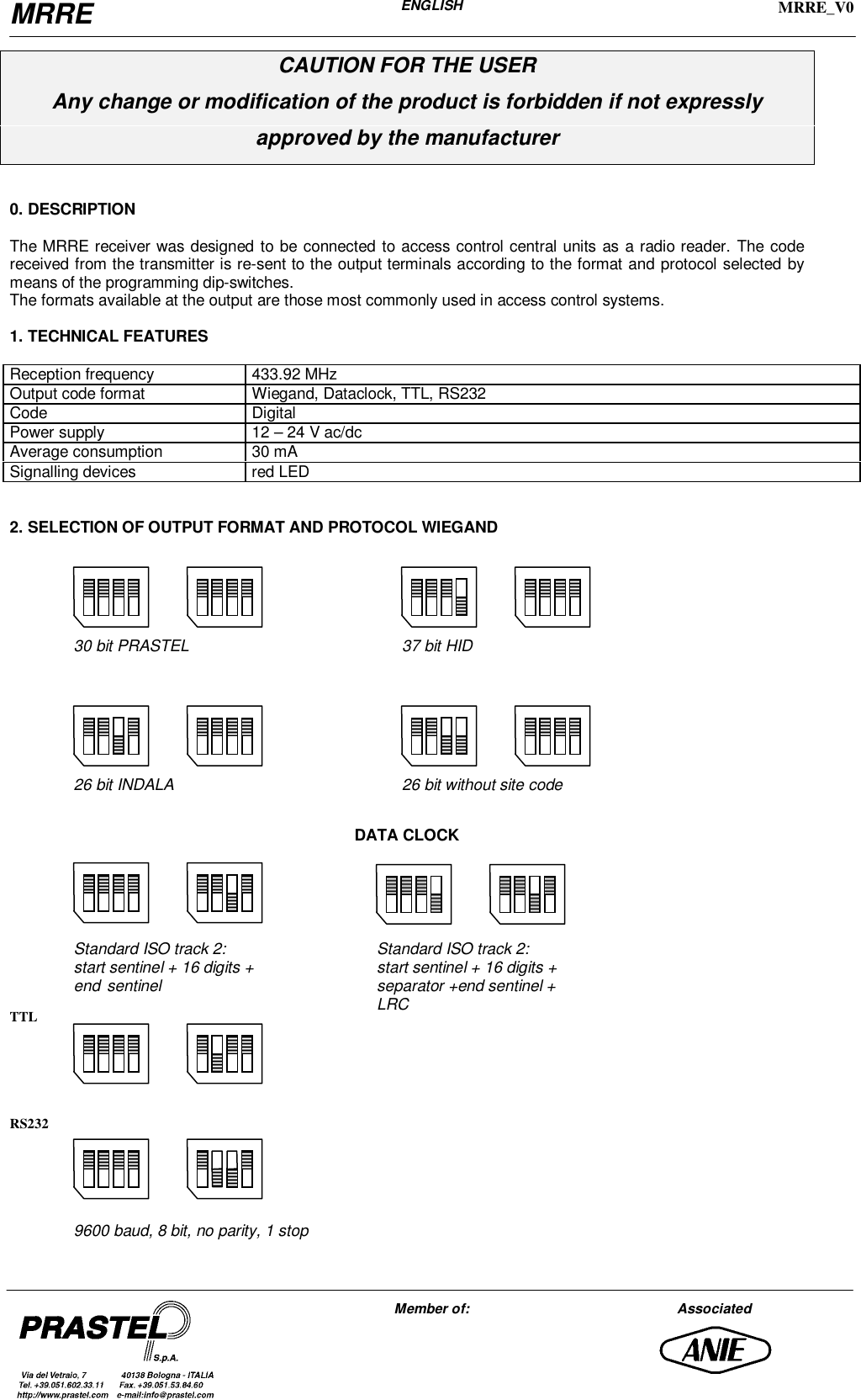
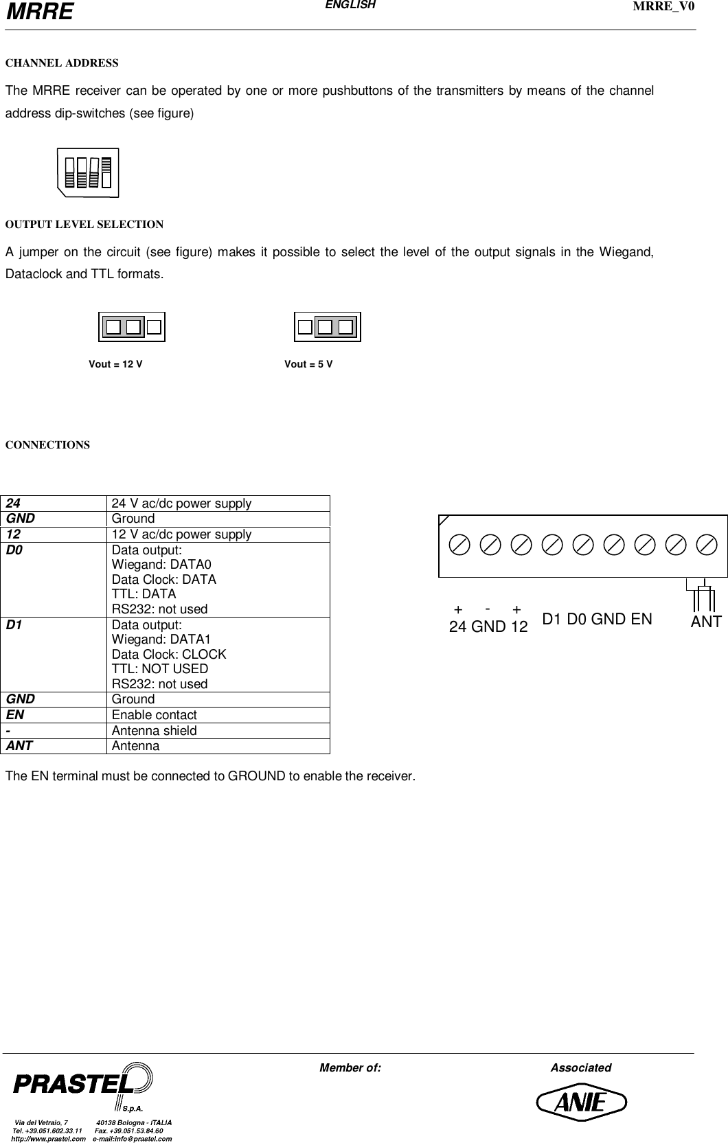
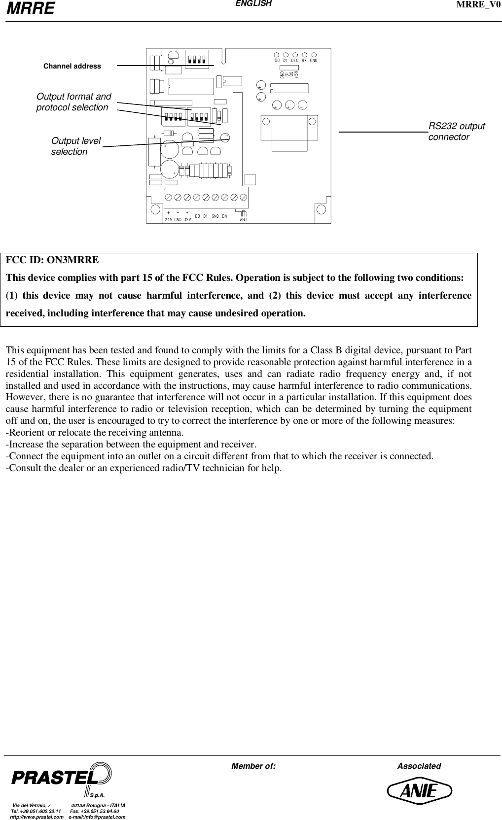
Prastel S p A MRRE User Manual INSTRUCTION MANUAL

Prastel S.p.A. INSTRUCTION MANUAL

INSTRUCTION MANUAL

MRREENGLISHMRRE_V0Member of: AssociatedCAUTION FOR THE USERAny change or modification of the product is forbidden if not expresslyapproved by the manufacturer0. DESCRIPTIONThe MRRE receiver was designed to be connected to access control central units as a radio reader. The codereceived from the transmitter is re-sent to the output terminals according to the format and protocol selected bymeans of the programming dip-switches.The formats available at the output are those most commonly used in access control systems.1. TECHNICAL FEATURESReception frequency 433.92 MHzOutput code format Wiegand, Dataclock, TTL, RS232Code DigitalPower supply 12 – 24 V ac/dcAverage consumption 30 mASignalling devices red LED2. SELECTION OF OUTPUT FORMAT AND PROTOCOL WIEGANDDATA CLOCKTTLRS23230 bit PRASTEL 37 bit HID26 bit INDALA 26 bit without site codeStandard ISO track 2:start sentinel + 16 digits +end sentinelStandard ISO track 2:start sentinel + 16 digits +separator +end sentinel +LRC9600 baud, 8 bit, no parity, 1 stop
MRREENGLISHMRRE_V0Member of: AssociatedCHANNEL ADDRESSThe MRRE receiver can be operated by one or more pushbuttons of the transmitters by means of the channeladdress dip-switches (see figure)OUTPUT LEVEL SELECTIONA jumper on the circuit (see figure) makes it possible to select the level of the output signals in the Wiegand,Dataclock and TTL formats.CONNECTIONS2424 V ac/dc power supplyGNDGround1212 V ac/dc power supplyD0Data output:Wiegand: DATA0Data Clock: DATATTL: DATARS232: not usedD1Data output:Wiegand: DATA1Data Clock: CLOCKTTL: NOT USEDRS232: not usedGNDGroundENEnable contact-Antenna shieldANTAntennaThe EN terminal must be connected to GROUND to enable the receiver.Vout = 12 V Vout = 5 V +     -     +24 GND 12 D1 D0 GND EN  ANT
MRREENGLISHMRRE_V0Member of: AssociatedFCC ID: ON3MRREThis device complies with part 15 of the FCC Rules. Operation is subject to the following two conditions:(1) this device may not cause harmful interference, and (2) this device must accept any interferencereceived, including interference that may cause undesired operation.This equipment has been tested and found to comply with the limits for a Class B digital device, pursuant to Part15 of the FCC Rules. These limits are designed to provide reasonable protection against harmful interference in aresidential installation. This equipment generates, uses and can radiate radio frequency energy and, if notinstalled and used in accordance with the instructions, may cause harmful interference to radio communications.However, there is no guarantee that interference will not occur in a particular installation. If this equipment doescause harmful interference to radio or television reception, which can be determined by turning the equipmentoff and on, the user is encouraged to try to correct the interference by one or more of the following measures:-Reorient or relocate the receiving antenna.-Increase the separation between the equipment and receiver.-Connect the equipment into an outlet on a circuit different from that to which the receiver is connected.-Consult the dealer or an experienced radio/TV technician for help.RS232 outputconnectorChannel addressOutput format andprotocol selectionOutput levelselection

Navigation menu