Prastel S p A MRRE User Manual INSTRUCTION MANUAL
Prastel S.p.A. INSTRUCTION MANUAL
INSTRUCTION MANUAL

MRRE
ENGLISH
MRRE_V0
Member of: Associated
CAUTION FOR THE USER
Any change or modification of the product is forbidden if not expressly
approved by the manufacturer
0. DESCRIPTION
The MRRE receiver was designed to be connected to access control central units as a radio reader. The code
received from the transmitter is re-sent to the output terminals according to the format and protocol selected by
means of the programming dip-switches.
The formats available at the output are those most commonly used in access control systems.
1. TECHNICAL FEATURES
Reception frequency 433.92 MHz
Output code format Wiegand, Dataclock, TTL, RS232
Code Digital
Power supply 12 – 24 V ac/dc
Average consumption 30 mA
Signalling devices red LED
2. SELECTION OF OUTPUT FORMAT AND PROTOCOL WIEGAND
DATA CLOCK
TTL
RS232
30 bit PRASTEL 37 bit HID
26 bit INDALA 26 bit without site code
Standard ISO track 2:
start sentinel + 16 digits +
end
sentinel
Standard ISO track 2:
start sentinel + 16 digits +
separator +end sentinel +
LRC
9600 baud, 8 bit, no parity, 1 stop
MRRE
ENGLISH
MRRE_V0
Member of: Associated
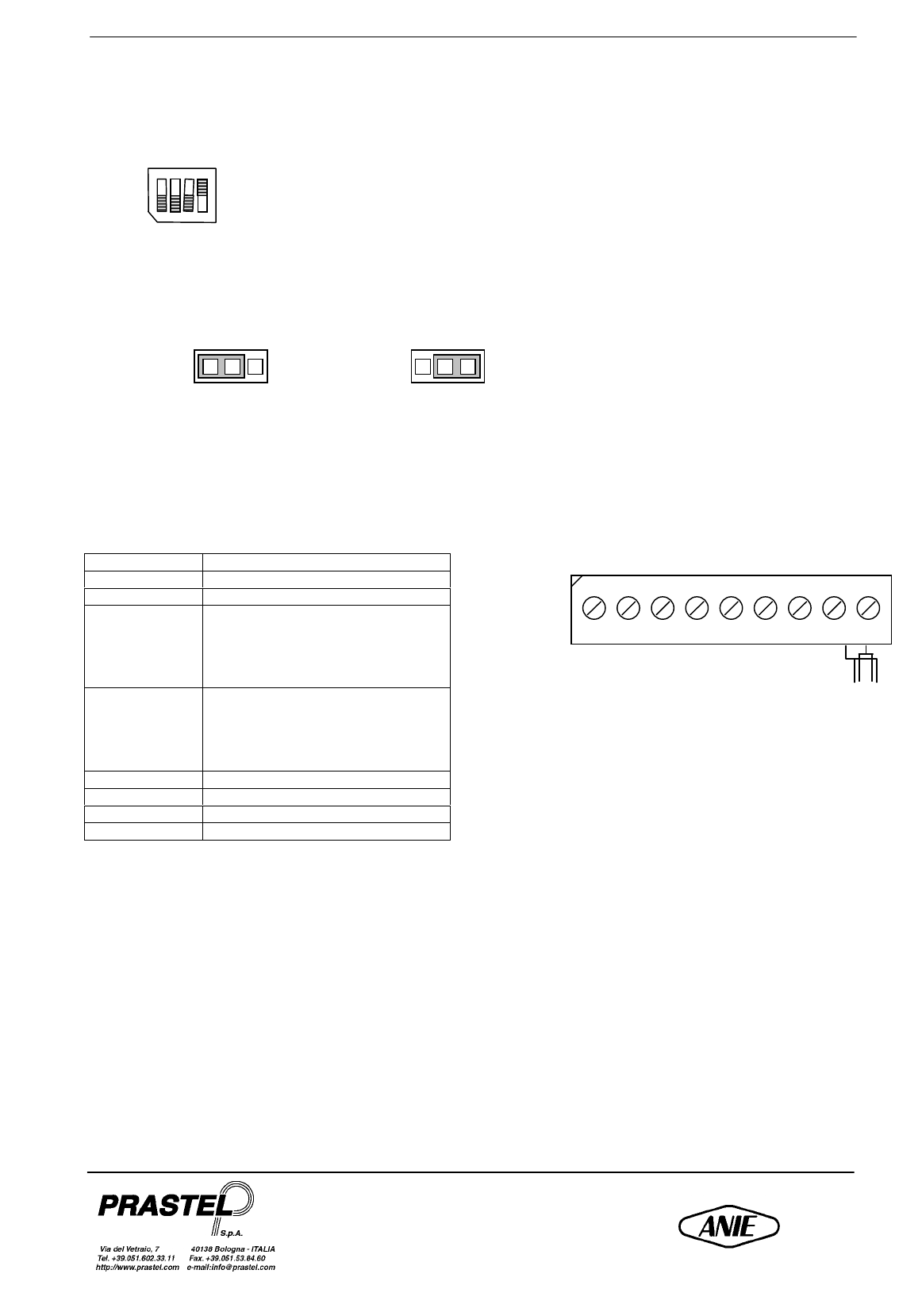
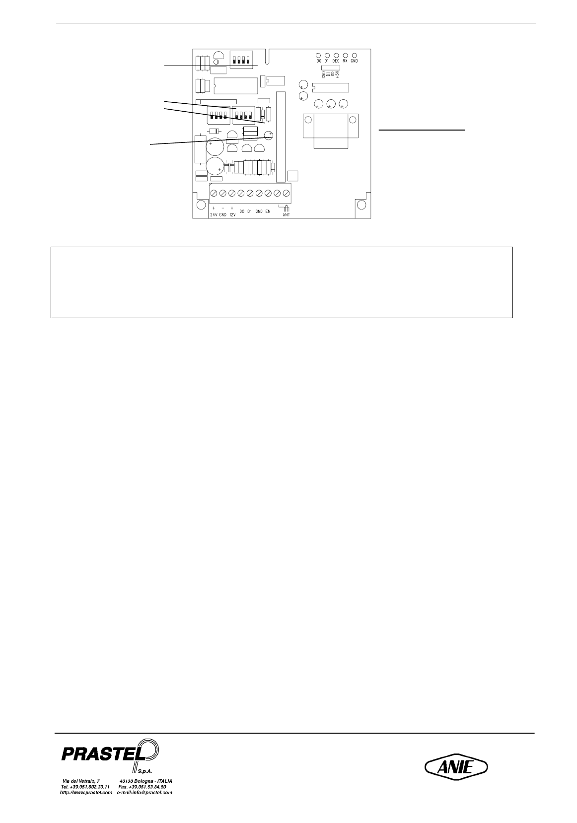
CHANNEL ADDRESS
The MRRE receiver can be operated by one or more pushbuttons of the transmitters by means of the channel
address dip-switches (see figure)
OUTPUT LEVEL SELECTION
A jumper on the circuit (see figure) makes it possible to select the level of the output signals in the Wiegand,
Dataclock and TTL formats.
CONNECTIONS
24
24 V ac/dc power supply
GND
Ground
12
12 V ac/dc power supply
D0
Data output:
Wiegand: DATA0
Data Clock: DATA
TTL: DATA
RS232: not used
D1
Data output:
Wiegand: DATA1
Data Clock: CLOCK
TTL: NOT USED
RS232: not used
GND
Ground
EN
Enable contact
-
Antenna shield
ANT
Antenna
The EN terminal must be connected to GROUND to enable the receiver.
Vout = 12 V Vout = 5 V
+ - +
24 GND 12 D1 D0 GND EN ANT
MRRE
ENGLISH
MRRE_V0
Member of: Associated
FCC ID: ON3MRRE
This device complies with part 15 of the FCC Rules. Operation is subject to the following two conditions:
(1) this device may not cause harmful interference, and (2) this device must accept any interference
received, including interference that may cause undesired operation.
This equipment has been tested and found to comply with the limits for a Class B digital device, pursuant to Part
15 of the FCC Rules. These limits are designed to provide reasonable protection against harmful interference in a
residential installation. This equipment generates, uses and can radiate radio frequency energy and, if not
installed and used in accordance with the instructions, may cause harmful interference to radio communications.
However, there is no guarantee that interference will not occur in a particular installation. If this equipment does
cause harmful interference to radio or television reception, which can be determined by turning the equipment
off and on, the user is encouraged to try to correct the interference by one or more of the following measures:
-Reorient or relocate the receiving antenna.
-Increase the separation between the equipment and receiver.
-Connect the equipment into an outlet on a circuit different from that to which the receiver is connected.
-Consult the dealer or an experienced radio/TV technician for help.
RS232 output
connector
Channel address
Output format and
protocol selection
Output level
selection