Precision Enterprise PDC320 Wireless Parking Sensor User Manual PKC0RE BackUp Sensor indd
Precision Enterprise Ltd Wireless Parking Sensor PKC0RE BackUp Sensor indd
UserManual.wiki
>
Precision Enterprise
>
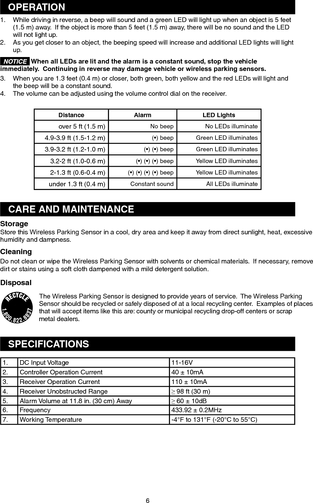
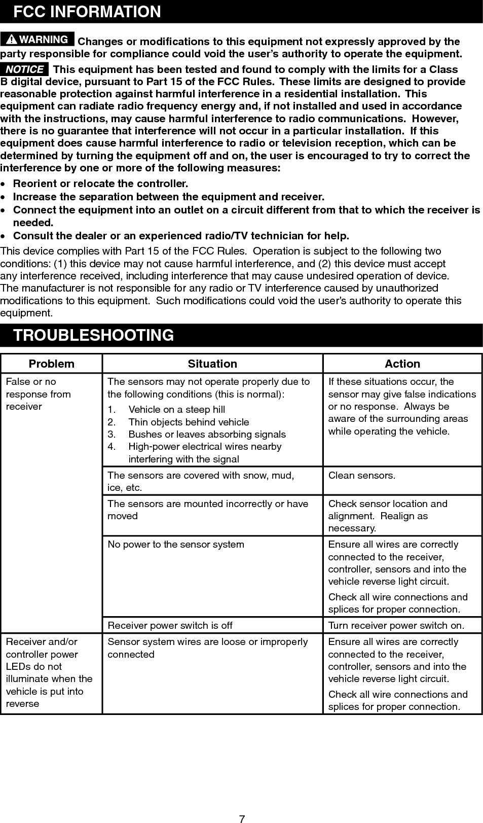
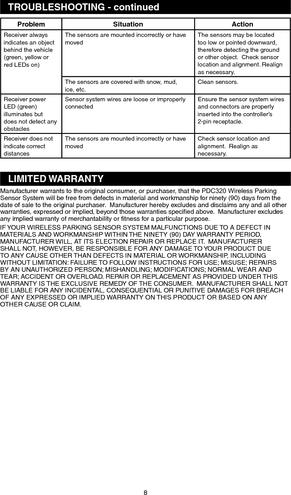
PDC320 User Manual
manual
Navigation menu
Upload a User Manual
Namespaces
Wiki Guide
HTML
PDF
Info
Views
User Manual
Discussion / Help
Navigation