Precision Enterprise PDC320 Wireless Parking Sensor User Manual PKC0RE BackUp Sensor indd
Precision Enterprise Ltd Wireless Parking Sensor PKC0RE BackUp Sensor indd
manual
Wireless Parking Sensor
Model No.: PDC320
Owner’s Manual
32 :( 5
PIW
P IW
P IW
P IW
P IW
/()7 5,*+ 7
2))
21
Read these instructions completely before using this product.
Retain this Owner’s Manual for future reference.

CONTENTS
SAFETY PRECAUTIONS................................................................................................................ 2
Wireless Parking Sensor Safety..............................................................................................2
INTRODUCTION .............................................................................................................................2
FEATURES......................................................................................................................................3
INSTALLATION.............................................................................................................................4-5
OPERATION....................................................................................................................................6
CARE AND MAINTENANCE........................................................................................................... 6
Storage ...................................................................................................................................6
Cleaning..................................................................................................................................6
Disposal ..................................................................................................................................6
SPECIFICATIONS ........................................................................................................................... 6
FCC INFORMATION .......................................................................................................................7
TROUBLESHOOTING..................................................................................................................7-8
LIMITED WARRANTY .....................................................................................................................8
SAFETY PRECAUTIONS
This safety alert symbol indicates that a potential personal injury hazard is present. The symbol
is usually used with a signal word (e.g., WARNING) which designates the degree or level of hazard
seriousness.
The signal word WARNING indicates a hazardous situation which, if not avoided, could result in
death or serious injury.
The signal word NOTICE indicates a situation which can cause damage to the product, other
personal property and/or to the environment, or cause the product to operate improperly.
The combination of the safety alert symbol and signal word is used in safety messages throughout
this manual and on safety labels on this product.
All safety messages that follow have WARNING level hazards. Failure to
comply could result in death or serious injury.
Wireless Parking Sensor Safety
When installing the Wireless Parking Sensor, the vehicle must be turned off with the vehicle in park
and the park brake applied.
Do not attempt to install the Wireless Parking Sensor while the engine is operating.
Do not modify the wiring in any way.
Only install the Wireles Parking Sensor to a 12-volt DC system. Connecting to anything other than a
12-volt DC system may damage the Sensor components or the vehicle electrical system.
If you are not confident working with 12-volt DC vehicle wiring, have the Wireless Parking Sensor
professionally installed.
This device as well as other wireless devices may be subject to interference. Interference may be
caused by cell phones, Bluetooth headsets, Wi-Fi routers, power lines and other various electrical
equipment.
Keep all power cords and wires away from the vehicle’s mechanical controls.
Do not install the Wireless Parking Sensor to the front of your vehicle.
Do not use in a vehicle which has an alarm or horn when driving in reverse.
Do not paint or spray the sensors.
INTRODUCTION
The Wireless Parking Sensor is an automatic object warning system, used when backing up a vehicle.
Information about the clearance between the vehicle and an object is displayed on the receiver inside
the vehicle.
When the vehicle is driven in reverse, the rear sensors mounted on the license plate transmit a
signal. If the signal detects an object, it sends a signal to the controller. These signals are analyzed
by the controller’s microprocessor. When the system reads ultrasonic signals that shows the obstacle
is moving from one detection zone to another, it activated automatically with a three seconds RF signal
This sends a signal to the receiver which identifies the clearance between the rear of the vehicle and
the object. The distance is indicated with tones and LED indicators on the receiver.
2
POWER
POWER
RIGHT
LEFT
OFF
ON
FEATURES
x Detects objects or people from approximately 5 ft (1.5 m) away
x Indicates the clearance between the vehicle and the object through audible alarm and red, yellow
or green LED indicator lights
x Adjustable alarm volume
x Two rear sensors for optimum object detection
x Wireless receiver can be dash-mounted for easy visibility
x Reduces the danger of harm or damage due to overseen objects
x System activates automatically when car is shifted into reverse
x Quick and easy two-wire installation
13
2
4
POWER
0.4m/1.3ft
5
0.6m/2.0ft
1.0m/3.3ft
21
1.2m/4.0ft
1.5m/5.0ft
LEFT RIGHT
7
20
18 19 6
17 8c
16
8a 8b
8d
8e
12
9
8
13 11 10
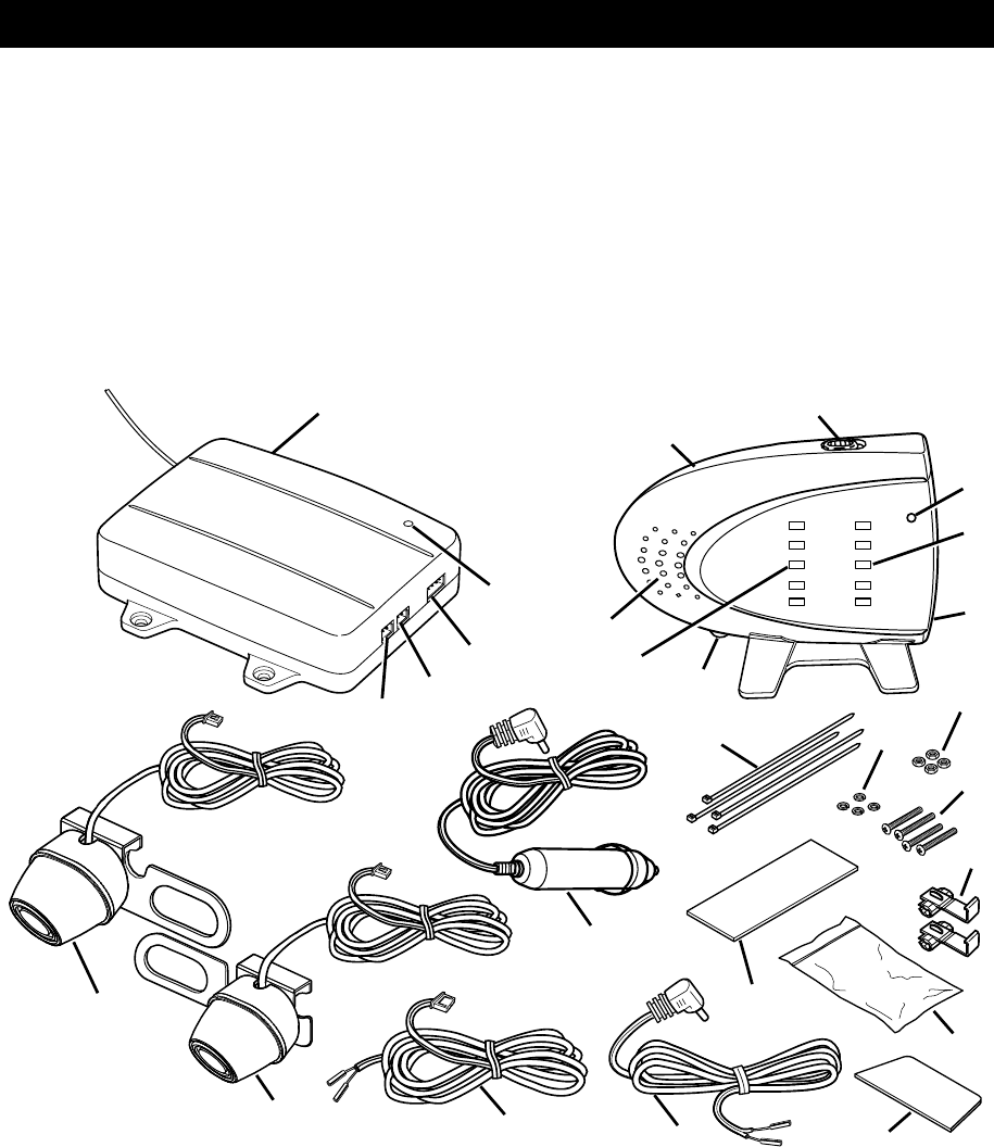
9. Controller Mounting Pad
10. Receiver Mounting Pad
11. Receiver Power Cord
12. Receiver Cigarette Lighter/Accessory
Socket Power Cord
13. Controller Power Cord
14. Right Sensor
15. Left Sensor
16. Left Sensor Port
17. Right Sensor Port
18. Controller Power Port
19. Left Sensor LED Lights
20. Alarm Speaker
21. Controller Power LED
15
14
Legend
1. Controller
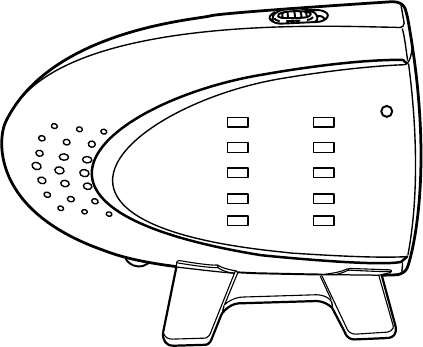
2. Receiver
3. ON/OFF Switch
4. Receiver Power LED
5. Right Sensor LED Lights
6. Volume Control
7. 12-volt DC Power Port
8. Hardware Bag
8a) Ties
8b) Lock Washers
8c) Nuts
8d) Screws
8e) Wire Connectors
3
POWER
POWER
RIGHT
LEFT
INSTALLATION
Some states or local governments may have regulations or laws that restrict the
use of anything that might impair the clear view of a license plate. Check local laws for
compliance.
For the Parking Sensor to be properly installed, it must be wired into the vehicle’s
taillight harness. If you are not comfortable or knowledgeable with 12-volt DC wiring, have the
system professionally installed.
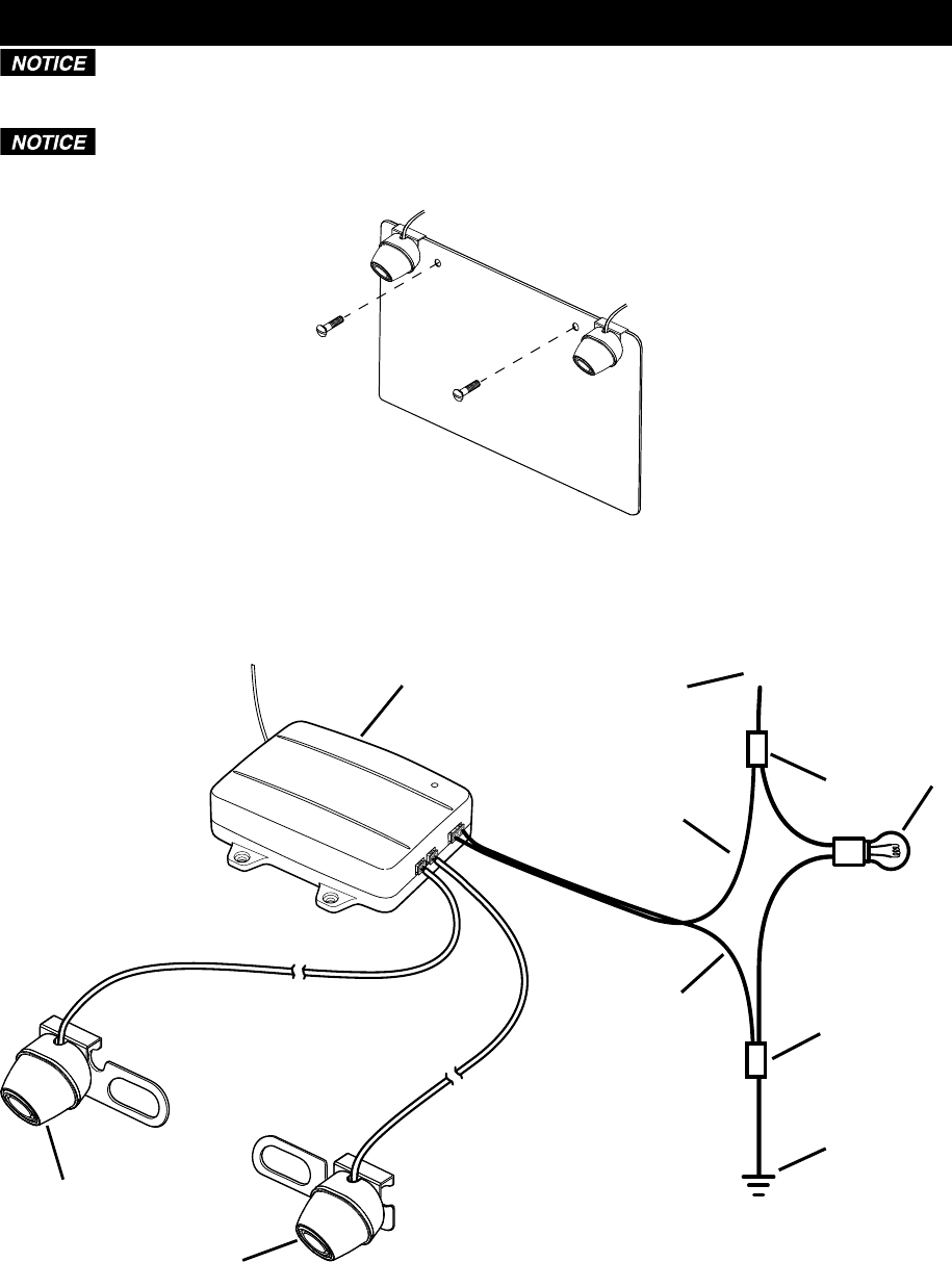
1. Remove the screws that hold the license plate to the vehicle.
2. Position the left and right sensor mounting plates behind the license plate.
3. Insert the screws through the license plate and the sensor mounting plates.
4. Install the screws to secure the sensors to the vehicle.
1
+
2
34
7
6
3
5
9
8
Legend
1. Controller
2. Positive (+) Wire from Reverse Light
3. Wire Connector
4. Reverse Light
5. Negative (-) Wire from Reverse Light
6. Negative (-) Controller Power Wire (Black)
7. Positive (+) Controller Power Wire (Red)
8. Right Sensor
9. Left Sensor
4
5. Determine which are the positive (+) and negative (-) wires for the reverse lights on the vehicle.
You can use either the right- or left-side reverse light wires. For help locating the vehicle’s
reverse light circuit, contact your vehicle’s manufacturer for vehicle-specific wiring diagrams.
6. Remove the vehicle’s negative (-) battery cable.
2
1
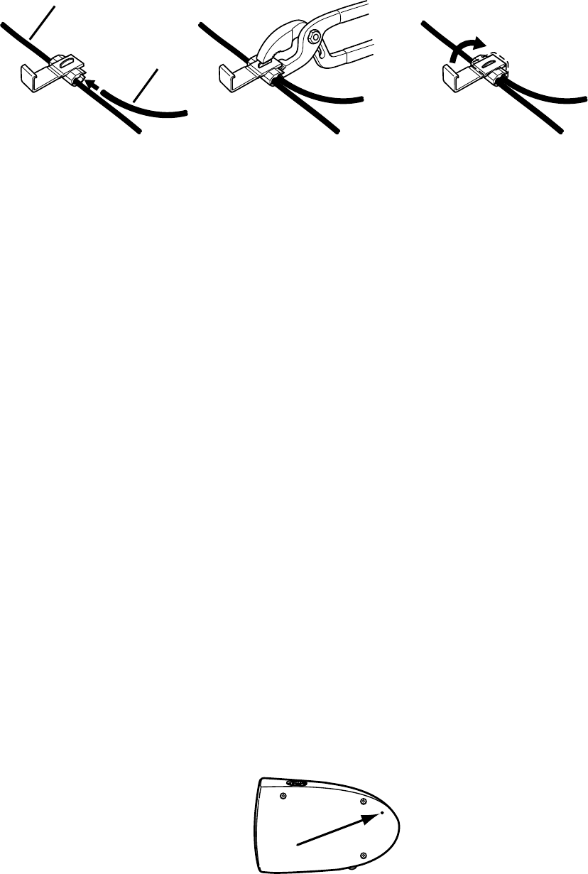
Legend
1. Wire from Vehicle
2. Wire from Controller
7. Once the proper wires for the reverse lights have been determined, the controller wires must
be spliced into the vehicle wires using the supplied wire connectors. If you choose to wire the
controller using a different method, you must be knowledgeable in 12-volt DC electrical practices.
8. The red positive (+) wire from the controller splices into the positive (+) wire from the reverse
lights and the black negative (-) wire from the controller splices into the negative (-) wire from the
reverse lights.
9. Position the connector around the vehicle wire you are splicing into.
10. Slide the appropriate wire from the controller into the connector.
11. Crimp the metal clamp using a pliers to ensure a good connection and then close the lock of the
wire connector. Do this for both the positive (+) and negative (-) wires from the reverse light.
12. Decide on a suitable mounting position for the controller and mount it using the screws from the
hardware bag or the adhesive-backed mounting pad. It must be mounted in an area where the
wires from the sensors can be plugged into it.
13. Reconnect the vehicle’s negative (-) battery cable.
14. Plug the controller power wire plug and the left and right sensor plugs into the controller.
15. Find a suitable mounting position inside the vehicle for the receiver where it can be easily seen
and heard, but not in a position where it can obstruct your vision when driving.
16. Use the adhesive-backed mounting pad to secure it to the desired mounting position. The angle
of the receiver can be adjusted by loosening the screw on the back and tilting the receiver.
17. The receiver can be powered using the receiver cigarette lighter/accesory socket power cord or
the receiver power cord. If you are going to hard wire it using the receiver power cord, you must
find a switched positive (+) and negative (-) wire from the vehicle wire harness.
18. Plug the receiver power cord into the power port of the receiver.
19. If using the receiver cigarette lighter/accesory socket power cord, plug it into a 12-volt DC power
port.
20. Route and secure all wires as needed.
21. When using the system for the first time, the controller and receiver must recognize each other.
22. Turn the power switch for the receiver to the ON position. The green power LED on the receiver
will light.
23. With park brake still applied, turn the vehicle ignition switch to the ON position only. Do not start
the vehicle.
24. Shift the vehicle to reverse to power the controller.
OFF
ON
25. Using a small piece of wire or paper clip, push the learn button on the back of the receiver.
26. When a mutual frequency has been found, the receiver will beep twice. If the frequency is not
found, a long beep will sound. If this happens, switch the receiver off and back on and push
the learn button again to repeat the procedure. If a problem still persists, check the system
installation.
5

OPERATION
1. While driving in reverse, a beep will sound and a green LED will light up when an object is 5 feet
(1.5 m) away. If the object is more than 5 feet (1.5 m) away, there will be no sound and the LED
will not light up.
2. As you get closer to an object, the beeping speed will increase and additional LED lights will light
up.
When all LEDs are lit and the alarm is a constant sound, stop the vehicle
immediately. Continuing in reverse may damage vehicle or wireless parking sensors.
3. When you are 1.3 feet (0.4 m) or closer, both green, both yellow and the red LEDs will light and
the beep will be a constant sound.
4. The volume can be adjusted using the volume control dial on the receiver.
Distance Alarm LED Lights
over 5 ft (1.5 m) No beep No LEDs illuminate
4.9-3.9 ft (1.5-1.2 m) sBEEP Green LED illuminates
3.9-3.2 ft (1.2-1.0 m) ssBEEP Green LED illuminates
3.2-2 ft (1.0-0.6 m) sssBEEP Yellow LED illuminates
2-1.3 ft (0.6-0.4 m) ssssBEEP Yellow LED illuminates
under 1.3 ft (0.4 m) Constant sound All LEDs illuminate
CARE AND MAINTENANCE
Storage
Store this Wireless Parking Sensor in a cool, dry area and keep it away from direct sunlight, heat, excessive
humidity and dampness.
Cleaning
Do not clean or wipe the Wireless Parking Sensor with solvents or chemical materials. If necessary, remove
dirt or stains using a soft cloth dampened with a mild detergent solution.
Disposal
The Wireless Parking Sensor is designed to provide years of service. The Wireless Parking
Sensor should be recycled or safely disposed of at a local recycling center. Examples of places
that will accept items like this are: county or municipal recycling drop-off centers or scrap
metal dealers.
SPECIFICATIONS
1. DC Input Voltage 11-16V
2. Controller Operation Current 40 ± 10mA
3. Receiver Operation Current 110 ± 10mA
4. Receiver Unobstructed Range 98 ft (30 m)
5. Alarm Volume at 11.8 in. (30 cm) Away 60 ± 10dB
6. Frequency 433.92 ± 0.2MHz
7. Working Temperature -4°F to 131°F (-20°C to 55°C)
6

FCC INFORMATION
Changes or modifications to this equipment not expressly approved by the
party responsible for compliance could void the user’s authority to operate the equipment.
This equipment has been tested and found to comply with the limits for a Class
B digital device, pursuant to Part 15 of the FCC Rules. These limits are designed to provide
reasonable protection against harmful interference in a residential installation. This
equipment can radiate radio frequency energy and, if not installed and used in accordance
with the instructions, may cause harmful interference to radio communications. However,
there is no guarantee that interference will not occur in a particular installation. If this
equipment does cause harmful interference to radio or television reception, which can be
determined by turning the equipment off and on, the user is encouraged to try to correct the
interference by one or more of the following measures:
x Reorient or relocate the controller.
x Increase the separation between the equipment and receiver.
x Connect the equipment into an outlet on a circuit different from that to which the receiver is
needed.
x Consult the dealer or an experienced radio/TV technician for help.
This device complies with Part 15 of the FCC Rules. Operation is subject to the following two
conditions: (1) this device may not cause harmful interference, and (2) this device must accept
any interference received, including interference that may cause undesired operation of device.
The manufacturer is not responsible for any radio or TV interference caused by unauthorized
modifications to this equipment. Such modifications could void the user’s authority to operate this
equipment.
TROUBLESHOOTING
Problem Situation Action
False or no
response from
receiver
The sensors may not operate properly due to
the following conditions (this is normal):
Vehicle on a steep hill 1.
Thin objects behind vehicle2.
Bushes or leaves absorbing signals 3.
High-power electrical wires nearby4.
interfering with the signal
If these situations occur, the
sensor may give false indications
or no response. Always be
aware of the surrounding areas
while operating the vehicle.
The sensors are covered with snow, mud,
ice, etc.
Clean sensors.
The sensors are mounted incorrectly or have
moved
Check sensor location and
alignment. Realign as
necessary.
No power to the sensor system Ensure all wires are correctly
connected to the receiver,
controller, sensors and into the
vehicle reverse light circuit.
Check all wire connections and
splices for proper connection.
Receiver power switch is off Turn receiver power switch on.
Receiver and/or
controller power
LEDs do not
illuminate when the
vehicle is put into
reverse
Sensor system wires are loose or improperly
connected
Ensure all wires are correctly
connected to the receiver,
controller, sensors and into the
vehicle reverse light circuit.
Check all wire connections and
splices for proper connection.
7

TROUBLESHOOTING - continued
Problem Situation Action
Receiver always
indicates an object
behind the vehicle
(green, yellow or
red LEDs on)
The sensors are mounted incorrectly or have
moved
The sensors may be located
too low or pointed downward,
therefore detecting the ground
or other object. Check sensor
location and alignment. Realign
as necessary.
The sensors are covered with snow, mud,
ice, etc.
Clean sensors.
Receiver power
LED (green)
illuminates but
does not detect any
obstacles
Sensor system wires are loose or improperly
connected
Ensure the sensor system wires
and connectors are properly
inserted into the controller’s
2-pin receptacle.
Receiver does not
indicate correct
distances
The sensors are mounted incorrectly or have
moved
Check sensor location and
alignment. Realign as
necessary.
LIMITED WARRANTY
Manufacturer warrants to the original consumer, or purchaser, that the PDC320 Wireless Parking
Sensor System will be free from defects in material and workmanship for ninety (90) days from the
date of sale to the original purchaser. Manufacturer hereby excludes and disclaims any and all other
warranties, expressed or implied, beyond those warranties specified above. Manufacturer excludes
any implied warranty of merchantability or fitness for a particular purpose.
IF YOUR WIRELESS PARKING SENSOR SYSTEM MALFUNCTIONS DUE TO A DEFECT IN
MATERIALS AND WORKMANSHIP WITHIN THE NINETY (90) DAY WARRANTY PERIOD,
MANUFACTURER WILL, AT ITS ELECTION REPAIR OR REPLACE IT. MANUFACTURER
SHALL NOT, HOWEVER, BE RESPONSIBLE FOR ANY DAMAGE TO YOUR PRODUCT DUE
TO ANY CAUSE OTHER THAN DEFECTS IN MATERIAL OR WORKMANSHIP, INCLUDING
WITHOUT LIMITATION: FAILURE TO FOLLOW INSTRUCTIONS FOR USE; MISUSE; REPAIRS
BY AN UNAUTHORIZED PERSON; MISHANDLING; MODIFICATIONS; NORMAL WEAR AND
TEAR; ACCIDENT OR OVERLOAD. REPAIR OR REPLACEMENT AS PROVIDED UNDER THIS
WARRANTY IS THE EXCLUSIVE REMEDY OF THE CONSUMER. MANUFACTURER SHALL NOT
BE LIABLE FOR ANY INCIDENTAL, CONSEQUENTIAL OR PUNITIVE DAMAGES FOR BREACH
OF ANY EXPRESSED OR IMPLIED WARRANTY ON THIS PRODUCT OR BASED ON ANY
OTHER CAUSE OR CLAIM.
8