Precyse Technologies BS24103000 PBS Base Station User Manual The iLocate Tracking Solutions
Precyse Technologies Inc PBS Base Station The iLocate Tracking Solutions
UserManual.wiki
>
Precyse Technologies
>
BS24103000 User Manual
>
users manual
Contents
1.
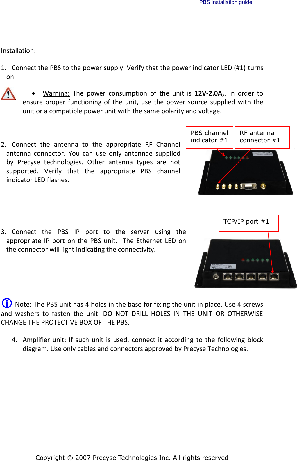
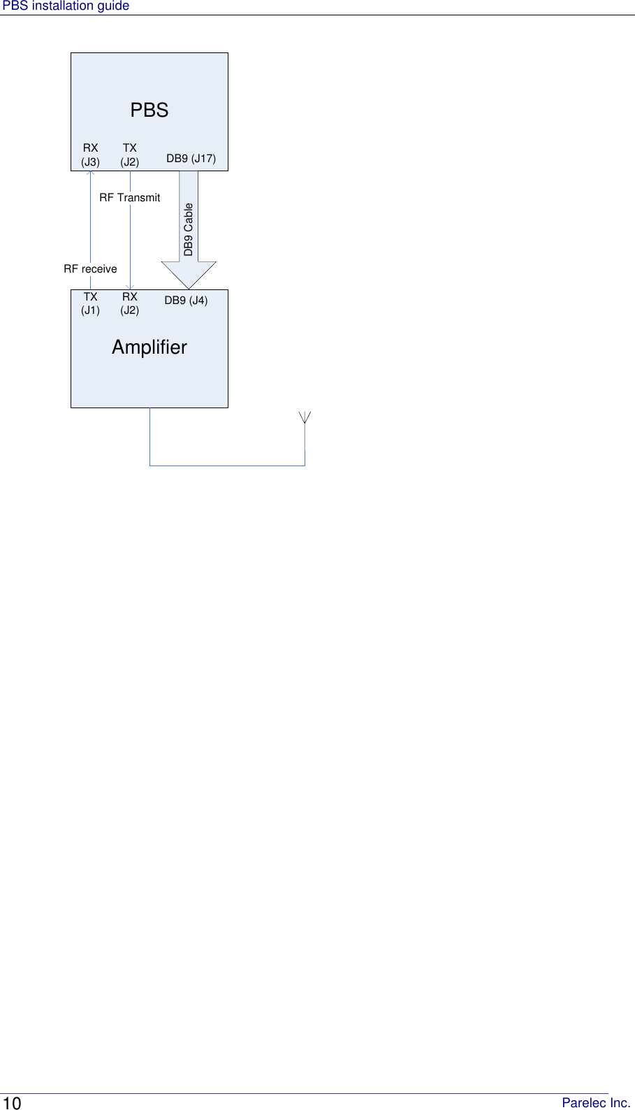
installation guide
2.
users manual
users manual
Navigation menu
Upload a User Manual
Namespaces
Wiki Guide
HTML
PDF
Info
Views
User Manual
Discussion / Help
Navigation