Precyse Technologies BS24103000 PBS Base Station User Manual The iLocate Tracking Solutions
Precyse Technologies Inc PBS Base Station The iLocate Tracking Solutions
Contents
- 1. installation guide
- 2. users manual
users manual
PBS installation guide
Copyright © 2007 Precyse Technologies Inc. All rights reserved
The iLocate Tracking
Solutions
PBS installation guide

PBS installation guide
Parelec Inc.
2
Regulatory Information/disclaimers
Installation and use of this Wireless Radio device must be in strict accordance with
the instructions included in the user documentation provided with the product. Any
changes or modifications made to this device that are not expressly approved by the
manufacturer may void the user’s authority to operate the equipment. The
Manufacturer is not responsible for any radio or television interference caused by
unauthorized modification of this device, of the substitution or attachment.
Manufacturer and its authorized resellers or distributors will assume no liability for
any damage or violation of government regulations arising from failing to comply
with these guidelines.
This equipment has been tested and found to comply with the limits for a Class B
digital device, pursuant to Part 15 of the FCC rules. These limits are designed to
provide reasonable protection against harmful interference in a residential
installation. This equipment generates, uses, and can radiate radio frequency energy
and, if not installed and used in accordance with the instructions, may cause harmful
interference to radio communications.
Instructions concerning human exposure to radio frequency electromagnetic fields:
To comply with FCC Section 1.307 (b) (1) for human exposure to radio frequency
electromagnetic fields, implement the following instruction:
A distance of at least 20cm. between the equipment and all persons should be
maintained during the operation of the equipment. The minimum distance will be
determined after testing has been completed.
This document is confidential and proprietary. No part of this document may be
reproduced, stored, or transmitted in any form or by any means without prior
written permission from Precyse technologies Inc.

PBS installation guide
Copyright © 2007 Precyse Technologies Inc. All rights reserved
Table of contents
Regulatory Information/disclaimers ............................................................................................. 2
Introduction ........................................................................................................................4
Acronyms ..................................................................................................................................... 4
Standards used throughout this guide ........................................................................................... 4
Audience and scope ...................................................................................................................... 4
Base Station unit (PBS) installation .................................................................................5
Verify PBS contents ..................................................................................................................... 5
PBS connectors and indicators ..................................................................................................... 6
PBS hardware installation ............................................................................................................ 8
Checking the installation ................................................................................................. 11
Visual check after connection ...................................................................................................... 11

PBS installation guide
Parelec Inc.
4
Introduction
The PBS is a component of the Precyse iLocate™ real time location system.
The PBS allows for 2-way RF communication with the Smart Agent tags, supporting
multi-frequency mode for unexpected RF interference protection. The PBS base station
is a low cost, low maintenance stand-alone device. This unit communicates with the
central iLocate™ server over existing Ethernet or Wi-Fi networks.
Acronyms
Acronym
Definition
PBS
RF Base Station
Beacon/PBC
RF Transmitter that is continuously transmitting its ID
PBS ID
ID number of PBS
SID
system ID – unique to each project
Tag
compact battery powered device, typically usually attached to
the monitored asset
Frame zone
straight line visibility zone
RSSI
Received Signal Strength Indicator
User area
All open and close area that is in use of the system and under its
control
Standards used throughout this guide
Symbol / font
Definition
Warnings and security notes
Additional notes for information
Audience and scope
This user guide describes the process for installing the Precyse Base Station (PBS) as part
of the iLocate™ RTLS system.

PBS installation guide
Copyright © 2007 Precyse Technologies Inc. All rights reserved
Theory of operation
The PBS base station is responsible for synchronizing all the other parts of the system
and transmitting data to and from the PC connected to it.
The GPS receiver in the PBS is used as an absolute timing and clock source.
Amplifier block: The amplifier box is connected to the PBS via a proprietary control
protocol.
Two of the four RF connectors are used as transmit and receive channels to the
amplifier. The other two SMA connectors are disabled (Internally, physically
disconnected).
The fifth RF port is a GPS antenna port.
Base Station unit (PBS) installation
Verify PBS contents
Each PBS unit consists of the following components:
Base station unit
Power supply unit
PBS installation guide
Parelec Inc.
6
Amplifier unit
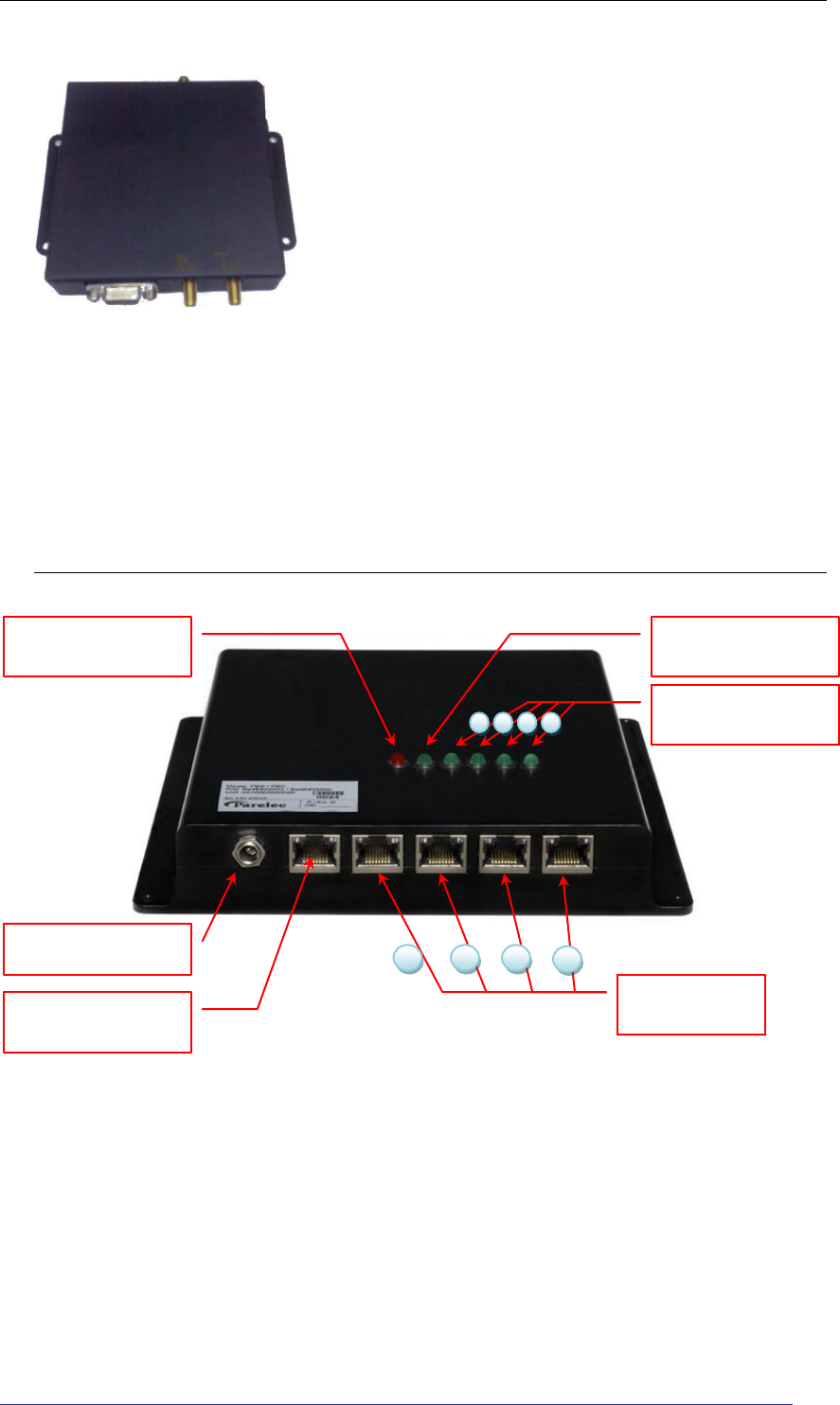
PBS connectors and indicators
PBS - front view
7. DC Power port
8. Heartbeat port
9-12. TCP\IP
ports 1-4
4
3
2
1
1. Power indicator
2. Synch indicator
3-6. PBS channel
indicators 1-4
1
2
3
4
PBS installation guide
Copyright © 2007 Precyse Technologies Inc. All rights reserved
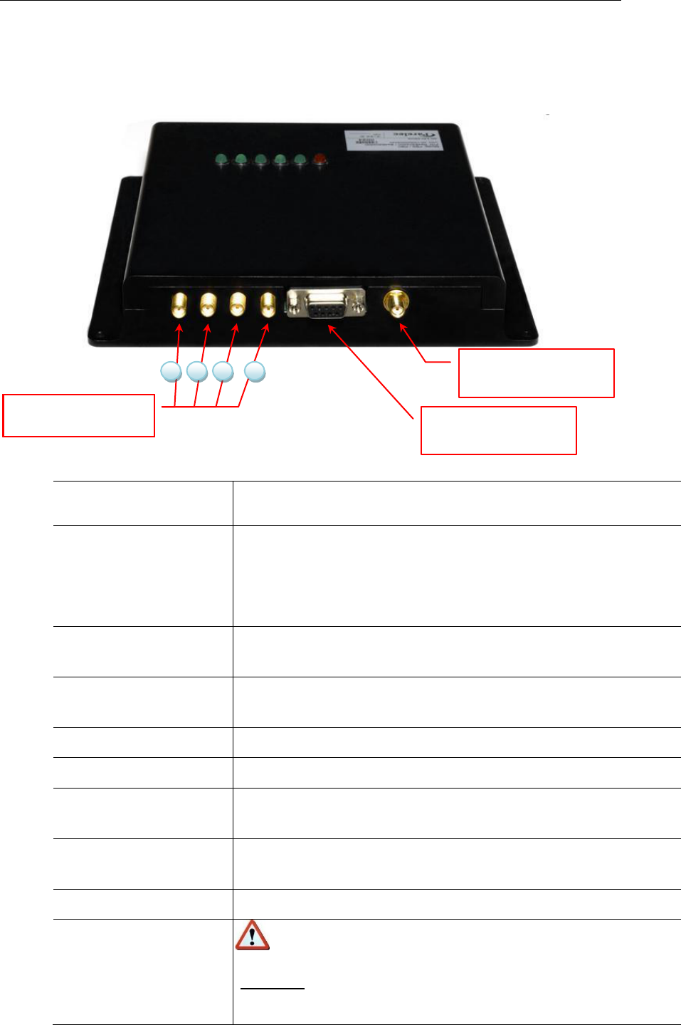
PBS - rear view
Connector /
indicator
Description
1. Power indicator
LED (red)
On - Power is connected.
Flashing - There is a problem with the power supply.
Off – power supply not connected.
2. Synch indicator
Synchronization LED (green)– Flashes once a second when
the system is active
3-6. PBS channel
indicators #1-4
Green LED (green) – flashes when a signal is sent on the
corresponding channel
7. DC Power port
DC power port (12V-2.08A, 25W MAX)
8. Heartbeat port
Not used at this stage
9-12. TCP\IP port 1-4
Network connector for corresponding channel. RJ45
connector.
13,16. RF Channel 1,4
antennae connectors
Physical antenna connector for the corresponding channel.
14, 15
RF transmit, RF receive – Connected to Amplifier unit.
17. External amplifier
connector
A DB9 connector that contains power and control
outputs.
Warning: Do not connect this port to a computer or any
other RS232 terminal equipment.
17. External amplifier
connector
18. Synch Generator
(GPS Antenna)
13-16. RF Channels
antennae connectors
4
2
1
3

PBS installation guide
Parelec Inc.
8
Connector /
indicator
Description
18. GPS Antenna
connector
Connect a GPS antenna (Either active or passive)
PBS hardware installation
Pre-installation checklist:
Determine the specific location for the PBS.
Ensure available power source (AC).
Available LAN port to connect to the iLocate ™ server.
Antennae.
PBS installation guide
Copyright © 2007 Precyse Technologies Inc. All rights reserved
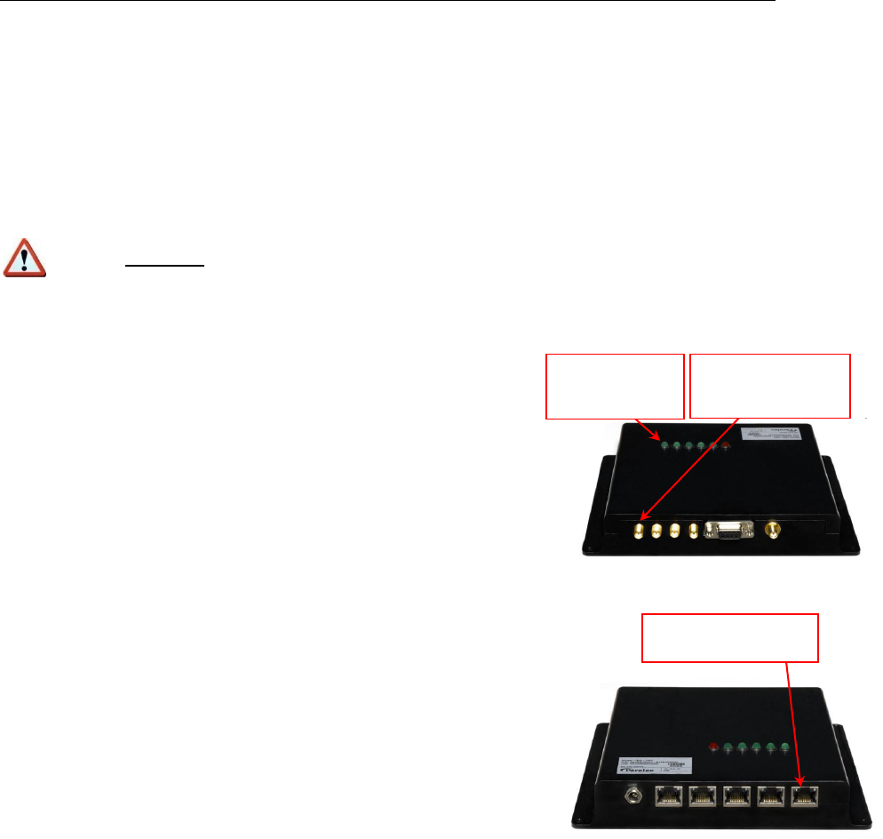
PBS channel
indicator #1
RF antenna
connector #1
TCP/IP port #1
Installation:
1. Connect the PBS to the power supply. Verify that the power indicator LED (#1) turns
on.
Warning: The power consumption of the unit is 12V-2.0A,. In order to
ensure proper functioning of the unit, use the power source supplied with the
unit or a compatible power unit with the same polarity and voltage.
2. Connect the antenna to the appropriate RF Channel
antenna connector. You can use only antennae supplied
by Precyse technologies. Other antenna types are not
supported. Verify that the appropriate PBS channel
indicator LED flashes.
3. Connect the PBS IP port to the server using the
appropriate IP port on the PBS unit. The Ethernet LED on
the connector will light indicating the connectivity.
Note: The PBS unit has 4 holes in the base for fixing the unit in place. Use 4 screws
and washers to fasten the unit. DO NOT DRILL HOLES IN THE UNIT OR OTHERWISE
CHANGE THE PROTECTIVE BOX OF THE PBS.
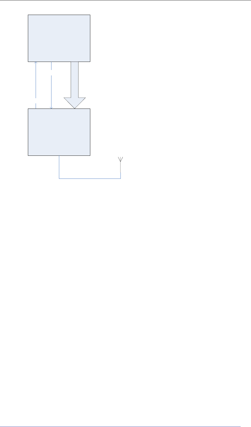
4. Amplifier unit: If such unit is used, connect it according to the following block
diagram. Use only cables and connectors approved by Precyse Technologies.
PBS installation guide
Parelec Inc.
10
PBS
Amplifier
RF receive
RF Transmit
DB9 Cable
TX
(J2)
TX
(J1) RX
(J2)
RX
(J3) DB9 (J17)
DB9 (J4)

PBS installation guide
Copyright © 2007 Precyse Technologies Inc. All rights reserved
Checking the installation
Visual check after connection
Verify that the power LED indicator (red) is on when the power is connected.
Verify that the appropriate PBS RF Channel indicator is on.
Verify that the Appropriate LAN LED indicator is on
Check connection of PBS to the network / server ( ping ) .
Appendix A: Marketing and installation
1. The product intended use and application:
The BS24103000 (PBS) is used as a radio base station for the iLocate system.
By transmitting a synchronization signal, and receiving transmissions from other
devices on the iLocate network it acts as a bridge between the iLocate hardware
and a personal computer.
2. The EUT is installed either indoors or outdoors (inside an appropriate sealed
box).
The installation requirements are proper site planning, infrastructure (AC supply
with an AC to DC adapter or DC supply, mechanical mounting, clearance around
it), sealed box (Per Precyse Tech’s requirements, an IP55 or equivalent
boxuninterrupted power supply where required, etc).
3. Marketing:
The EUT is sold to system integrators only. It is not available for non-
professionals.