Prime Electronics and Satellitics WA211P-X Wireless Access Point User Manual WA211P
Prime Electronics & Satellitics Inc. Wireless Access Point WA211P
User Manual

Wireless Access Point
User Manual

Wireless Access Point
Copyright
Copyright 2001 by this company. All rights reserved. No part of this
publication may be reproduced, transmitted, transcribed, stored in a
retrieval system, or translated into any language or computer language,
in any form or by any means, electronic, mechanical, magnetic, optical,
chemical, manual or otherwise, without the prior written permission of
this company.
This company makes no representations or warranties, either
expressed or implied, with respect to the contents hereof and
specifically disclaims any warranties, merchantability or fitness for any
particular purpose. Any software described in this manual is sold or
licensed "as is". Should the programs prove defective following their
purchase, the buyer (and not this company, its distributor, or its dealer)
assumes the entire cost of all necessary servicing, repair, and any
incidental or consequential damages resulting from any defect in the
software. Further, this company reserves the right to revise this
publication and to make changes from time to time in the contents
hereof without obligation to notify any person of such revision or
changes.
.
All brand and product names mentioned in this manual are trademarks and/or registered
trademarks of their respective holders.

Federal Communication Commission
Interference Statement
This equipment has been tested and found to comply with the limits for a Class B
digital device, pursuant to Part 15 of FCC Rules. These limits are designed to
provide reasonable protection against harmful interference in a residential
installation. This equipment generates, uses, and can radiate radio frequency
energy and, if not installed and used in accordance with the instructions, may cause
harmful interference to radio communications. However, there is no guarantee that
interference will not occur in a particular installation. If this equipment does cause
harmful interference to radio or television reception, which can be determined by
turning the equipment off and on, the user is encouraged to try to correct the
interference by one or more of the following measures:
1. Reorient or relocate the receiving antenna.
2. Increase the separation between the equipment and receiver.
3. Connect the equipment into an outlet on a circuit different from that to which the
receiver is connected.
4. Consult the dealer or an experienced radio/television technician for help.
Notice 1:
The changes or modifications not expressly approved by the party responsible for compliance
could void the user's authority to operate the equipment.
Notice 2:
Shielded interface cables, if any, must be used in order to comply with the emission
limits.
Notice 3:
This device complies with Part 15 of the FCC Rules. Operations is subject to the
following two conditions: (1) This devices may not cause harmful interference and
(2) This devices must accept any interference received including interference that
may cause undesired operation.
Caution: “ To comply with FCC RF exposure compliance requirements, a separation
distance of at least 20cm must be maintained between the antenna of this device
and all persons. Do not alter the antenna(s) which is equipped with this device”

Manual Contents
Purpose
This user guide gives you all the information to install and operate the
Wireless Access Point Device properly.
Structure
This user guide consists of five chapters:
Chapter 1 Introduction
This chapter introduce the feature and package contents of this
product before you proceed the Wireless Access Point
installation
Chapter 2 Installation
This chapter gives all the necessary information that to install the
Wireless Access Point
Chapter 3 Configuring the Wireless Access Point
This chapter contains step-by-step procedure on how to
configure the Wireless Access Point through the DFU utility or
the SNMP manager.
Chapter 4 Troubleshooting
This chapter provides solutions to problems usually encountered
during the installation and operation of the Wireless Access
Point
Chapter 5 Appendix

Wireless Access Point
This chapter contains definitions of technical terms and
acronyms commonly found when installing and configuring this
device
Table of Contents
Chapter 1 Introduction
1.1 Package Contents ..................................................... 1-1
1.2 System Requirements ............................................... 1-1
1.3 Features ……………………………….…………………1-2
1.4 Specification…..……………………….…………………1-2
Chapter 2 Installation
2.1 Hardware connection ..................................................... 2-1
2.2 LED Indicator .................................................................. 2-2
Chapter 3 Configuring the Wireless Access Point
3.1 Configure through DFU Utility .................................. 3-1
3.2 Configure through SNMP Manager .......................... 3-7
Chapter 4 Troubleshooting
4.1 Frequently Asked Questions .................................... 4-1
Chapter 5 Appendix

Chapter
1
Introduction
Introduction 1-1
Thank you for purchasing Wireless Access Point. This device features
the latest innovation wireless technology making the wireless
networking world happened. This manual guides you on how to install
and properly use the Wireless Access Point in order to take full
advantage of its features.
1.1 Package Contents
Make sure that you have the following items:
• One Wireless Access Point
• One AC Power Adapter
• One USB Cable
• One Installation Manual
• One CD-Title with AP manager Software and manual
If any of the above items are missing, contact your supplier as soon as
possible.
1.2 System Requirements
Before installation, please check the following requirements with your
equipment.

1-2 User Manual
• Pentium Based ( And Above ) IBM-Compatible PC System
• CD-ROM drive
• One Available USB Connector
• Windows 9x/ME/NT4.0/2000 Operating System with TCP/IP
protocol
• At least 500Kbytes of free disk space for utility and driver
installation
1.3 Features
• Highly Efficient Dipole Antennas Provide Extensive Range of
Operation
• Auto Fall-Back Data Rate for Long-Distance Communication and
Noisy Environments
• High-Speed Data Transmitter Rate Up to 11 Mbps
• Interoperable with IEEE 802.11b (DSSS) 2.4GHz-Compliant
Equipment
• Features Roaming, Best Access Point Selection, Load Balancing,
and Network Traffic Filtering
• 40-Bit or 128-Bit (optional) Wired Equivalent Privacy
• Free Software Driver Upgrades
• Auto Fallback Data Rate for Long-Distance Communication and
Noisy Environments
1.4 Specification
• Standard IEEE 802.11b

Introduction 1-3
• Signal Type DSSS(Direct Sequence Spread Spectrum)
• Modulation QPSK / BPSK / CCK
• Port One RJ 45 / One 10BASE-T
• Ethernet Interface IEEE802.3 10 BASET
• Antenna Dual Dipole Antenna
• Data Encryption 40 bit WEP encryption ,
128 bit KEY Length(otional)
• Frequency 2.4GHz –2.4835GHz
• Channel 11 Channels(US,Canada)
13 Channels(Europe)
14 Channel(Japan)
• Data Rate Up to 11Mbps(with automatic scale back)
• LED Indicators Power , Link(wired),Activity(wireless) status
• Power Input-AC 100-240V , 50-60Hz, 1A
Output-DC 5V/ 800mA
• Temperature Operating :0℃ to 55℃, 32℉ to 131℉
Storage : -20℃ to 70℃, -4℉ to 158℉
• Humidity 95% Non-Condensing
• Dimensions 206*142*35mm

Chapter
2
Installation
Installation 2-1
Before you proceed with the installation, it is necessary that you have
enough information about the Wireless Access point
2.1 Hardware Connection
1. Locate an optimum location for the Wireless Network Access
Point. The best place for your Wireless Network Access Point is
usually at the center of your wireless network, with line of sight to all
of your mobile stations.
2. Fix the direction of the antenna . Try to place it in a position which
can best cover your wireless network . Normally, the higher you place
the antenna, the better the performance will be. The antenna’s
position enhances the receiving sensitivity.
3. Connect an RJ-45 to the Wireless Network Access Point. Then,
connect the other end of the Ethernet cable to a switch or hub.
Wireless Network Access Point will then be connected to the 10/100
Network.
4. Connect the AC Power Adapter to the Wireless Network Access
Point’s. Power
5. Then, power on the Access Point.

2-2 User Manual
2.2 LED Indicator
The LED indicators located in the front of the panel shows the Wireless
Access Point status and connection activity.

Chapter
3
Configuring the Wireless Access
Point
Configuring 3-1
This chapter contain detains on how to configure your Wireless Access
Point as well as how to verify if your setting is correct during the
installation. We recommend that you follow the steps accordingly to
avoid future problems.
3.1 Configure through DFU utility
The DFU Utility is provided to configure the Wireless Access Point
setting through the USB port.
Note : Before start using the AP ,configure through DFU utility first.
Even if you won’t use the DFU to manager this AP in the future . When
first connect the AP to the USB port , the operating system will ask for
the driver upon detecting the device. Locate the driver into your CD and
the installation will go on automatically. (Windows 98 and Windows
2000 are supported). After completing the installation , configure
through the DFU utility to get the AP work.
Note: Be sure that there is no AP inserted at this installation
stage.
3-2 User Manual
Installing the DFU Utility
In order to install DFU Utility, execute/or double click DFU setup.exe
program which may find in the CD title . A wizard appears indicating the
completeness of installation process.
Configuring the Wireless Network Access Point with
the DFU Utility
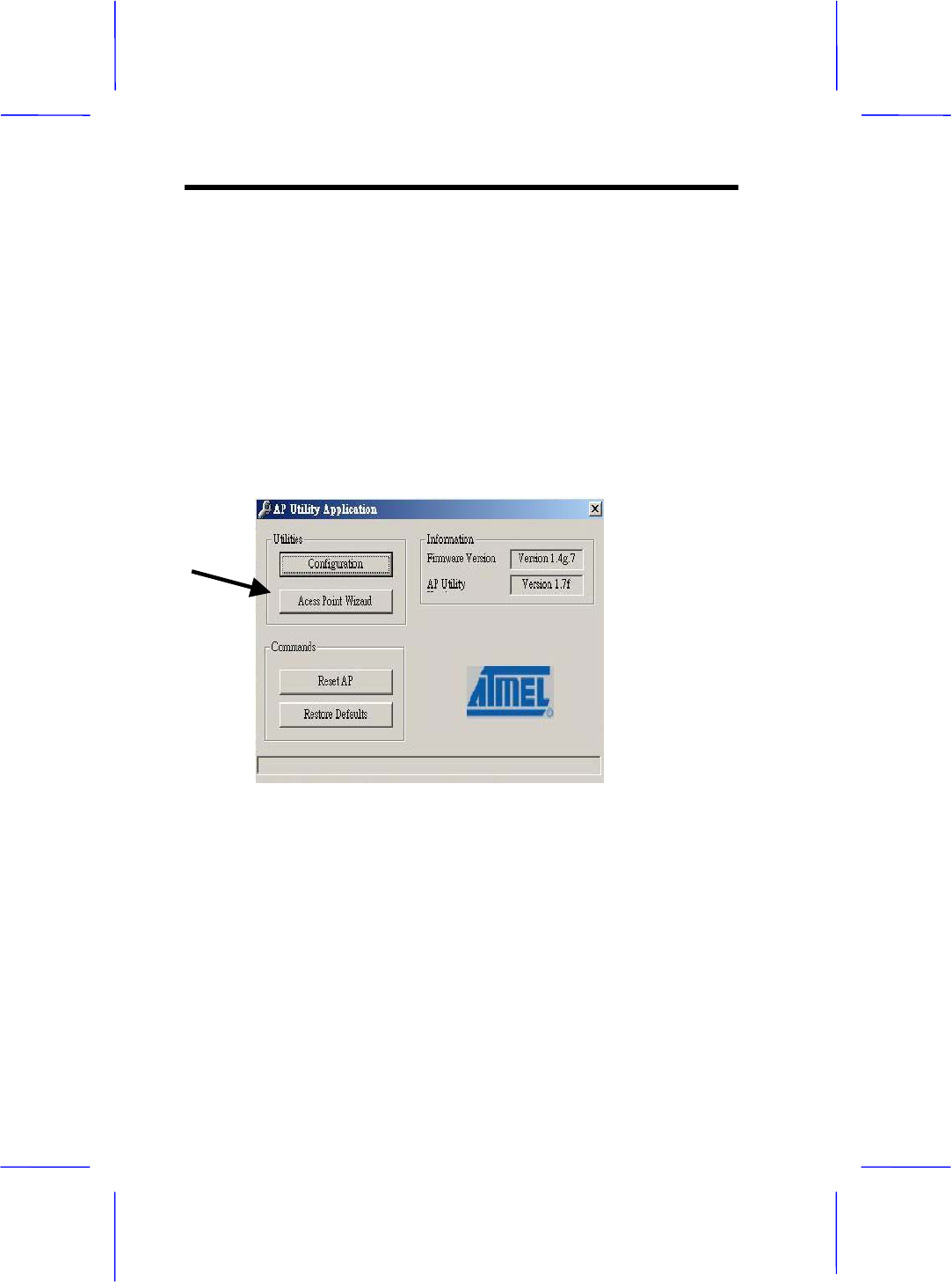
Boots up the DFU utility form the Windows start manual the
following dialog will apper.
Note : If this is your first time to use the DFU utility to configure
the Access Point. We do recommend you use the “Access Point
Wizard” as show above to go for the setting. This wizard will
guide you the most easy way to set up your device. Or you may
click the “Configuration” to get advanced setting.
Configuring 3-3
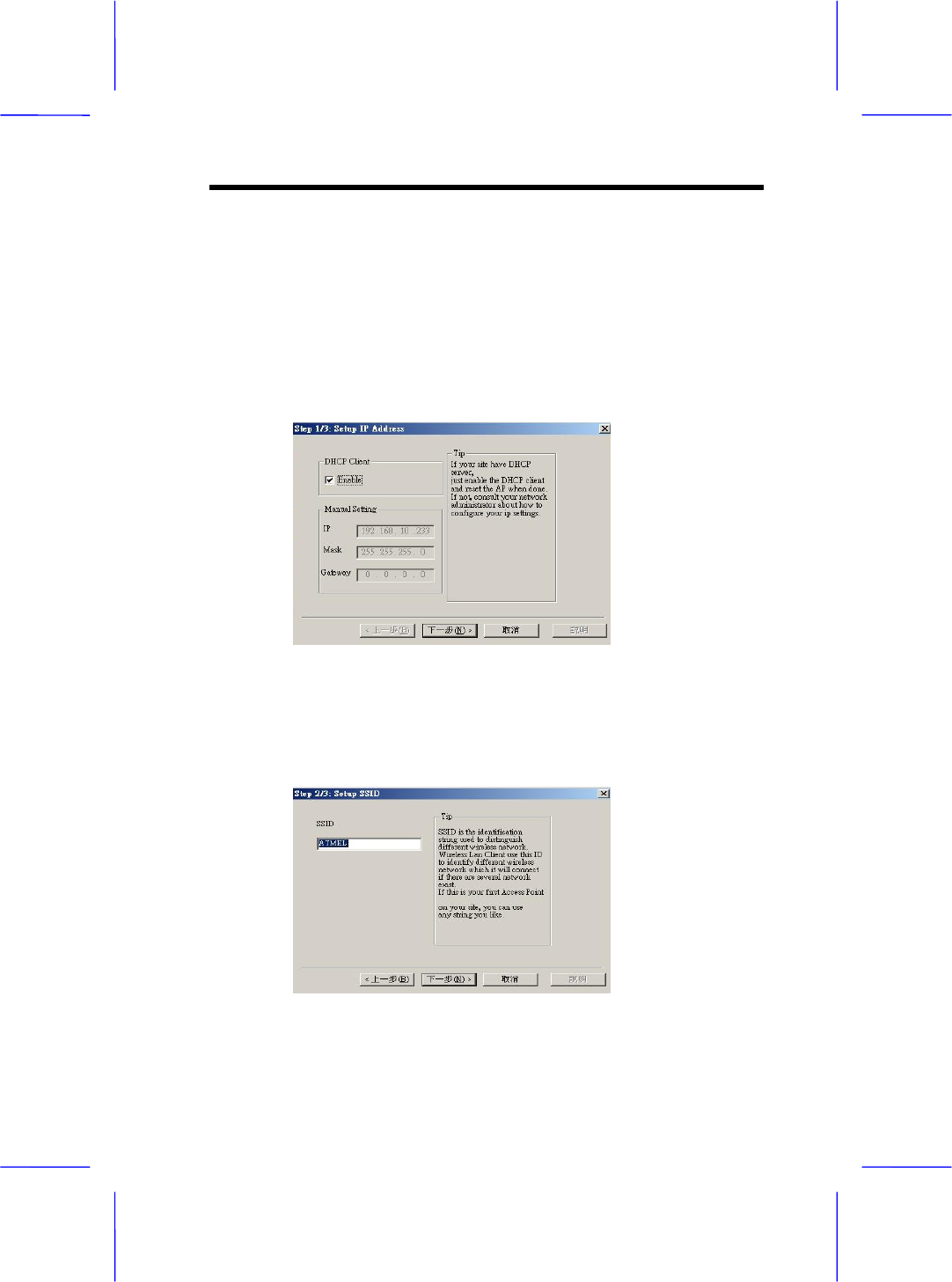
1 Access Point Wizard set up
1.1 Step up the IP address
Press the “Access Point Wizard” button, the following dialog
will show up .If there is a DHCP server in your Ethernet,
“Enable” DHCP Client. If not, consult your network administer
about how to configure your IP setting. After complete the
manual Setting ,click the “Next “ .
1.2 Step up the SSID
SSID is the identification string used to distinguish different
wireless network. Key in any sting you like to identify your
wireless network. Click “Next “to continue.
3-4 User Manual
Note : Be sure that the SSIDs of setting the Access Point
and the Wireless LAN card must be the same in order to
function properly.
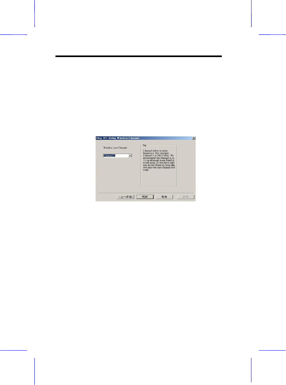
1.3 Setting up the Channel
Choose the channel you may use, then click “Finish” to
complete the setting.
Configuring 3-5
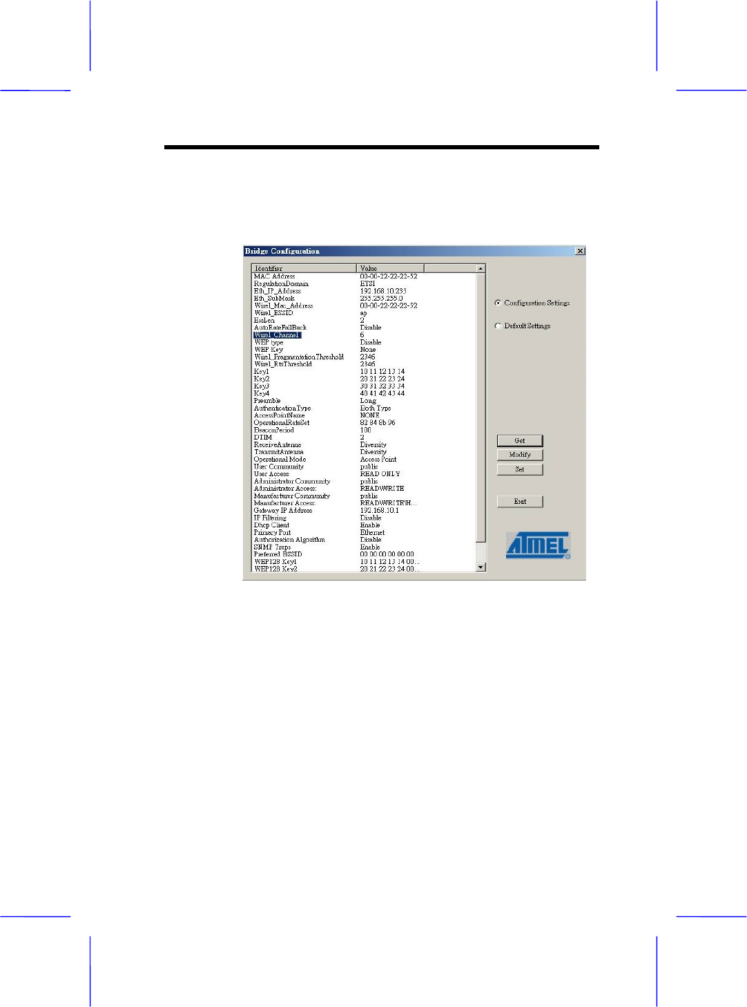
2 Advanced DFU Setting
2.1 Be sure that you have enough information to have the
advance setting before you boot up the following dialog.
2.2 You may use those buttons in the right side as shown in the
figure able for advance setting.
“ Get “ button details the current setting.
“ Modify “ button allows new setting parameters
“ Set “ button save and take any effect to the current
setting .
2.3 Click “Eth_IP-Address” to set the IP address used by the
AP .Click the other items to continue other setting.

3-6 User Manual
2.4 Click ”Eth_Submask” to set the subnet address .
2.5 Click “Wirel_ESSID” to give a name for the AP which may
find them to the network.
2.6 Click ”Wirel_Channel” to define the channel used by the
AP.
2.7 Click “Access Point Name” to name the AP .
2.8 Click “ Gateway IP Address” to set the Gateway IP
Address.
2.9 Click “Operation Mode “ to set the mode used by AP.Refer
to the Appendix for more information.
Lastly, close the application and unplug the cable.
Note: Chapter 5 contains definitions of technical terms and
acronyms commonly found when installing and configuring this
device.
3.2 Configure through SNMP Manager
The Access Point SNMP Manager is provided to manage the
Wireless Access Point through Ethernet.
Note: Before using the SNMP manager to configure the AP, please
check with your Network Administrator to have enough information for
the setting. .

Configuring 3-7
Note: Be sure that there is no AP inserted at this installation
stage.
Installing the Wireless Access Point SNMP manager
In order to install the SNMP manager, run the program setup.exe
which may find in the CD . Follow the instructions of the set-up program
and select the directory where the application will be installed. A
window wizard appears indicating the completeness of the installation
process.
Configuring the Wireless Network Access Point with
the SNMP Manager
Before configure the AP by the SNMP Manger utility ,Please set
the Access Point IP address following the procedure described
below. On the Windows Start Menu, choose
Start->Programs->SNMP Manger
Connect to Access Point –You can directly connect with the
Access Point by typing the appropriate IP address and community
in the panel,(The default password is” public”). Additionally you
select the User or Administrator Authority in the Authority
combo-box. User Authority allow you to view the Access Point
Configuration only, while Administrator Authority allow you to view
or change to the Access Point Configuration. After the above
configuration setting, press “OK”.
3-8 User Manual
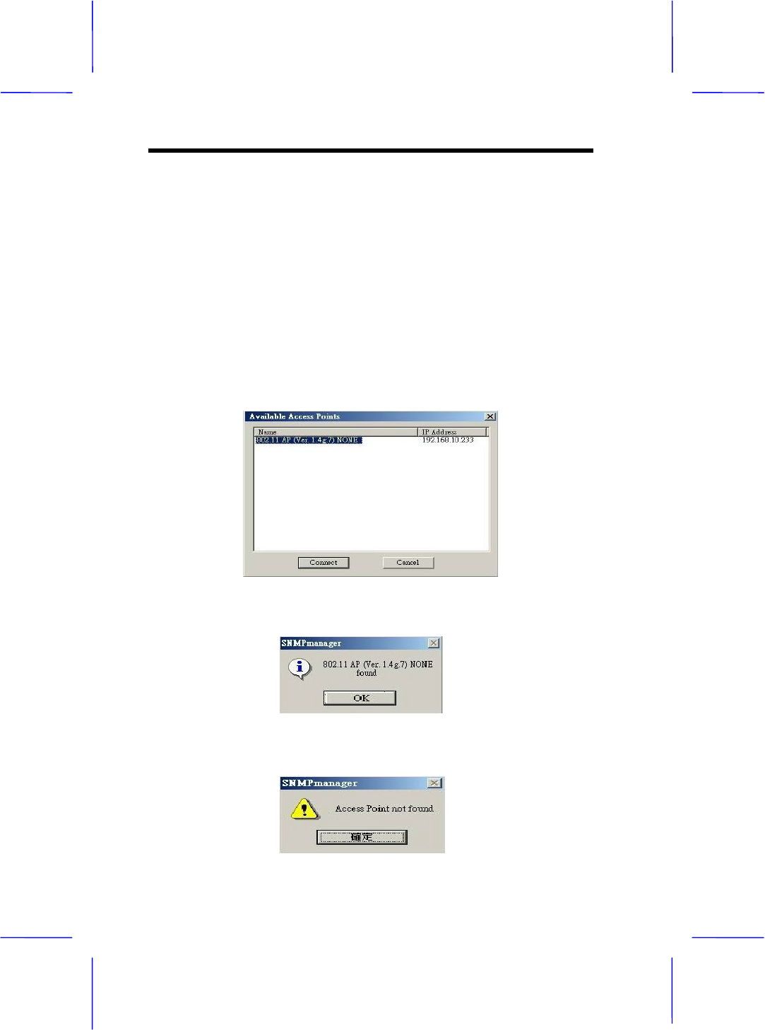
Find out Access Point–
1.This submenu allows you to find and connect with the Access
Point without the necessity of knowing its IP address. Choose
this submenu in order to find the Access Point and press
“Connect”. Window appears indicating the IP Address of the
selected Access Point and prompting you do select Authority
and appropriate password at the community field. Then press
“OK”.
2.The following window appears indicates a successful connection to
Access Point. Press “OK”
3.The following message appears an unsuccessful connection.

Configuring 3-9
4.If the above error message appears, please check whether the AP
has and appropriate IP address and been connected to the network.
5.a message “Get Configuration done” and the “IP Address” will appear
at the left and right button of the manual box once the connection
between the Access point been established.
File menu: The file menu contains the following enabled
submenus
● Close Connection AP – Terminates the connection with the
Access Point.
● Download changes – When all the desired values of the
parameters have been set you are able to download the
changes (save the changes) to the Access Point by selecting
this submenu.
● Options – Defines the polling interval according to which the
SNMP Manager polls the Access Point in order to update the
Associated Stations List.
Setup Menu: You are able to view or set the Access Point
parameters under the “Setup” menu, the section consists of
following submenus.
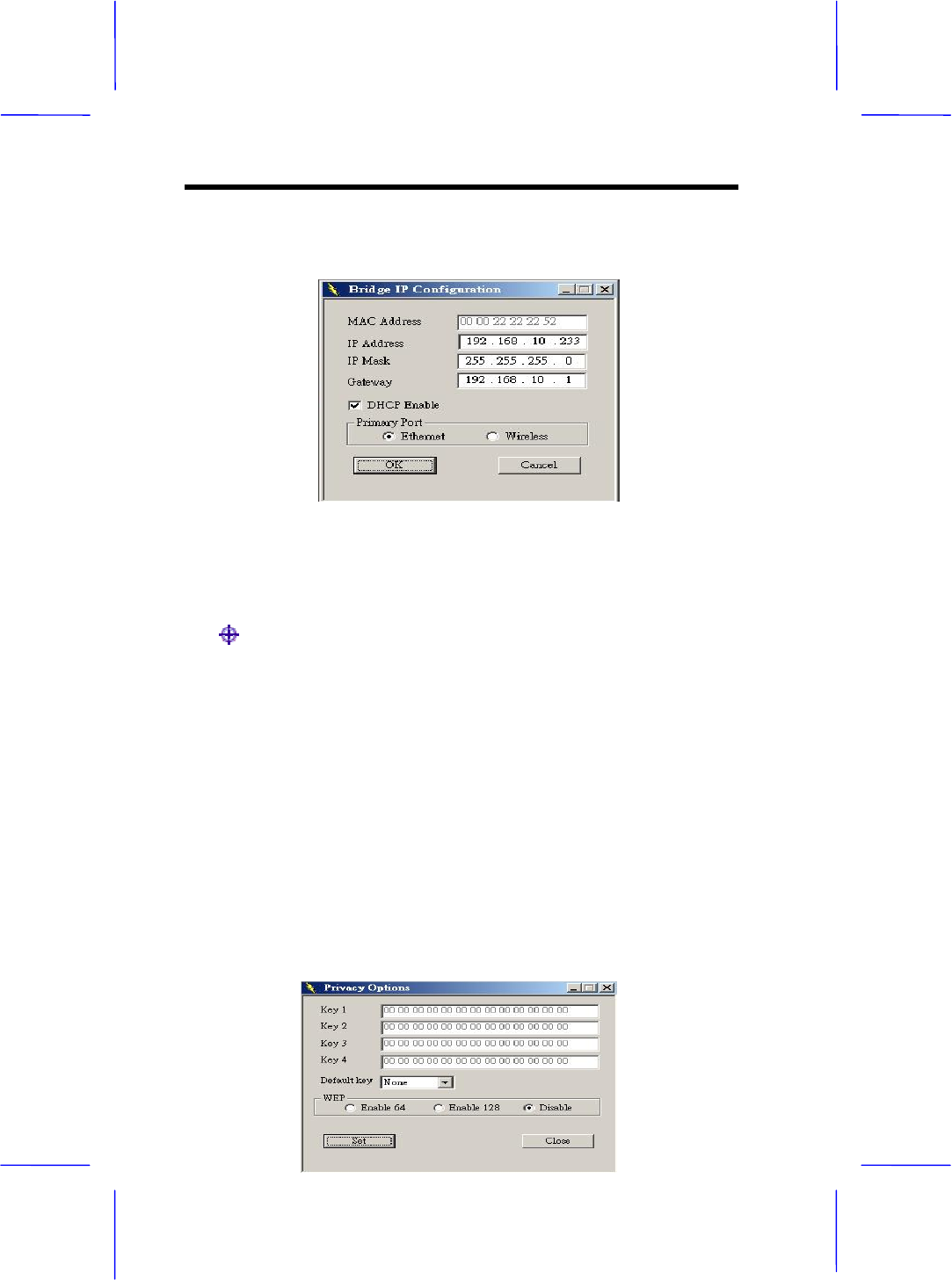
Setup->Bridge->IP Configuration or Filtering
● IP Configuration –
The “IP Address” and “IP Mask” can be modified through “IP
Configuration”, if DHCP client is not enabled. If DHCP client is
enabled the IP Address field displays the IP Address that was
dynamically assigned to the AP by the network DHCP server
and the IP Mask field displays the IP Mask utilized by the
network DHCP server. Additional you have to select the Primary
Port which is the interface that determines the “File” menu in
order to save them.
3-10 User Manual
●Filtering –
If IP Routing is enabled all the other protocols will be filtered out
offer than the IP protocol through the WLAN.
Setup->Wireless LAN ->Privacy Options or Operational
Settings or Authorized Mac Address
● Privacy Options –
By choosing this option you must define the encryption key
values of your choice. There are four 5 Hex digit encryption
keys available if you select 64 bit WEP or there are four 13
Hex digit encryption keys available if you select 128bit WEP.
The key is enabled only if you select it in the “Default Key”
option. Enable the WEP (Wired Equivalent Privacy) option in
order to activate WEP encryption for transmissions between
the stations and the Access Point. WEP is an authentication
algorithm which protects authorized Wireless LAN users
against eavesdropping.
Configuring 3-11
Note: The authentication type must be the same on the wireless station
and on the access point. All shared keys on the wireless station must
be the same as those on the access point with which the client station is
associated.
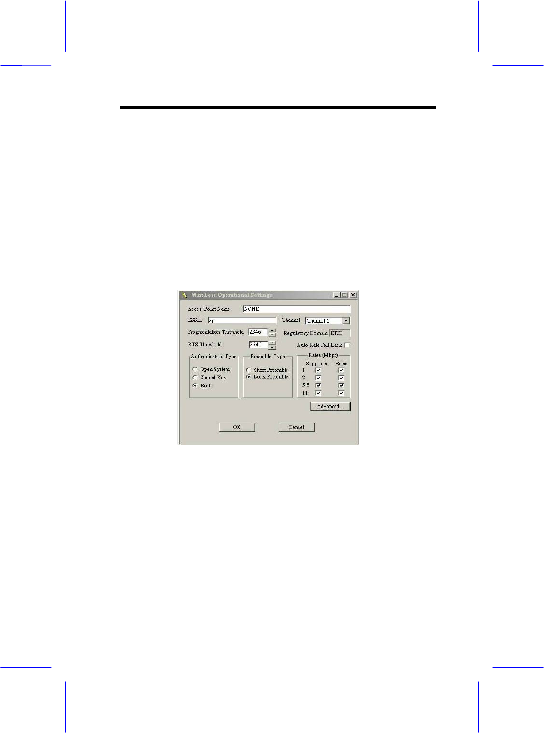
● Operational settings-
Using this option you can either view or modify the Wireless LAN
parameters of the Access Point . These parameters are described
below:
ESSID---It is an ASCII string up to 21 characters used to identify a
WLAN that prevents the unintentional merging of two co-located
WLANs. The ESSID value must be the same in all stations and Access
point in the extended WLAN. Select the ESSID to be used.
Channel---There are 14 channels available. The channels differ from
country to country. Select the channel to be used.
Fragmentation threshold---The size at which packets will be
fragmented. Choose a setting within a range of 256 to 2346 bytes.

3-12 User Manual
RTS Threshold--- Minimum packet size to require an RTS (Request To
Send). For packets smaller than this threshold, an RTS is not sent and
the packet is transmitted directly to the WLAN. This is the option for the
RTS Threshold activation.
Authentication Type-- Select Open System, Shared Key, or Both
Open System: With this setting any station in the WLAN can
associate with an Access Point and receive and transmitted data
(null authentication).
Shared Key: With this setting only stations using a shared key
encryption identified by the Access Point are allowed to associate
with it.
Both: with this setting stations communicate with the Access Point
either with or without data encryption.
Preamble Type (Short/Long)--- Preamble is the first subfield of PPDU,
which is the appropriate frame format for transmission to PHY (Physical
layer). There are two options, Short Preamble and Long Preamble. The
Short Preamble option improves throughput performance
Rate---By default the unit adoptively selects the highest possible rate
for transmission. Select the basic rates to be used among the following
options 1-2-5.5-11 (Mbps).
Auto Rate Fall Back--- When this is enabled the transmission rate is the
optimum rate. In case of obstacles or interference, the system will
automatically fall back.
Regulatory Domain--- The value of this field is already set and cannot
be modified.
Advanced Setting--- there are the following three operational modes
available.

Configuring 3-13
Access Point: This mode provides access for wireless stations to
wired LANs and from wired LANs to wireless stations.
Furthermore, wireless stations within the range of the Access Point
device may communicate with each other via the Access Point.
Access Point Client: This mode allows the connection of one or
more remote LANs with a central LAN, creating thus an extended
single virtual LAN. In this way, any station of the Remote LAN can
successfully communicate with any station of the central LAN, as if
all of them belonged to the same physical LAN. Wireless Stations
can’t associated with Access Point Clients. The Access Point
conducts the designated traffic to the appropriate wired or wireless
station.
Wireless Bridge: This mode allows two types of connections.
a. Point to point: The wireless bridge can communicate with a
specific Remote MAC Address.
b. Point to Multipoint: The Wireless bridge can communicate with
any Wireless Bridge available in the same channel. When
Authorization Algorithm (see the next menu – Authorized MAC
Address ), is enabled, the Wireless Bridge can communicate
For each mode you can either view or modify the Wireless
LAN parameters of the Wireless Operational Settings window.
In the Operational Mode Window there are the following
parameters.
Preferred BSS: It is enabled only if you select the Access Point C
lient option. BSS corresponds to the MAC Address of the desired
AP.
Remote MAC Address: It is enabled only if you select Point to
Point. It corresponds to the MAC Address of the Wireless Bridge of
the Remote LAN.

3-14 User Manual
●Authorized MAC Address – For security reasons the Access Point
has the ability to associate with authorized MAC Address stations, if the
authorization Table option is enabled. Thus, under the Authorized MAC
Address option you may press the following buttons.
The “Load file” button in order to load a file with the MAC Address
that can be associated with the Access Point (Authorized MAC
Address).
The “Download” button in order to download the Authorized MAC
Address to the Access Point.
The “Get” button in order to get from the Access Point the
Authorized MAC Addresses.
Setup->Enable SNMP Traps
● Enable SNMP traps –
Configuring 3-15
using this submenu you can either enable or disable SNMP traps,
which are messages displayed in the right bottom corner of the main
window indicating that an action related to the AP took place.
Permitted messages are: Trap association -- This trap message is
sent when a Station’s association request is received from the AP –
Bridge.
Trap association: Indicates the reception of an association request
packet and the sender Station’s successful association with the
Wireless Bridge.
Trap Disassociation: This trap message is sent when
disassociation notification packet is received from a station.
Trap Reset: This trap message is sent when the AP-Bridge resets.
Trap Setting IP Address with Ping: This trap message is sent when
the AP-Bridge IP address is sent with the transmission of a ping
message.
Trap Start UP: This trap message is sent when Bridge starts up.
Trap Failed To Erase Flash: This trap message is sent when
Bridge fails to erase flash.
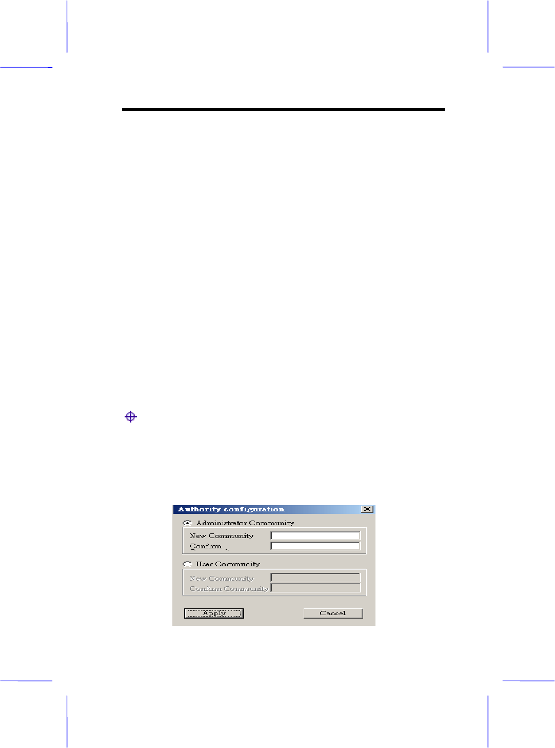
Setup->Authorization
● Authorization –
Using this submenu the Administrator can change the passwords
which referred to the community field for the User and the
Administrator Authority.
3-16 User Manual
Commands menu: Under this menu there are two submenus.
Commands->Reset device or Restore Default
● Reset device –
You can reset the Access Point. This action takes place after a user
makes configuration changes in order to initiate the changes.
● Restore Default –
You can restore the factory default values of the Access Point.
Info menu: Using this menu you can view a limited number of
statistics by choosing the “SNMP – Shot View” of the “Change
Mode” Software. There are the following submenus:
Info ->Wireless statistic or Ethernet statistics
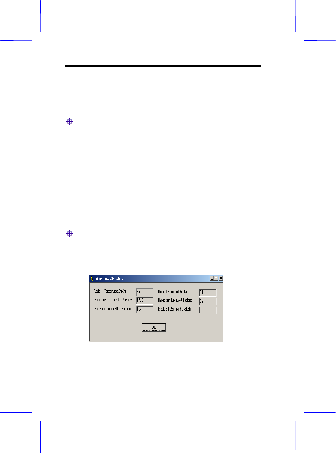
● Wireless statistics: This submenu reports the statistics concerning
the unit’s wireless activity. The meaning of the fields, concerning all the
statistics, is giving in the following table.
Configuring 3-17
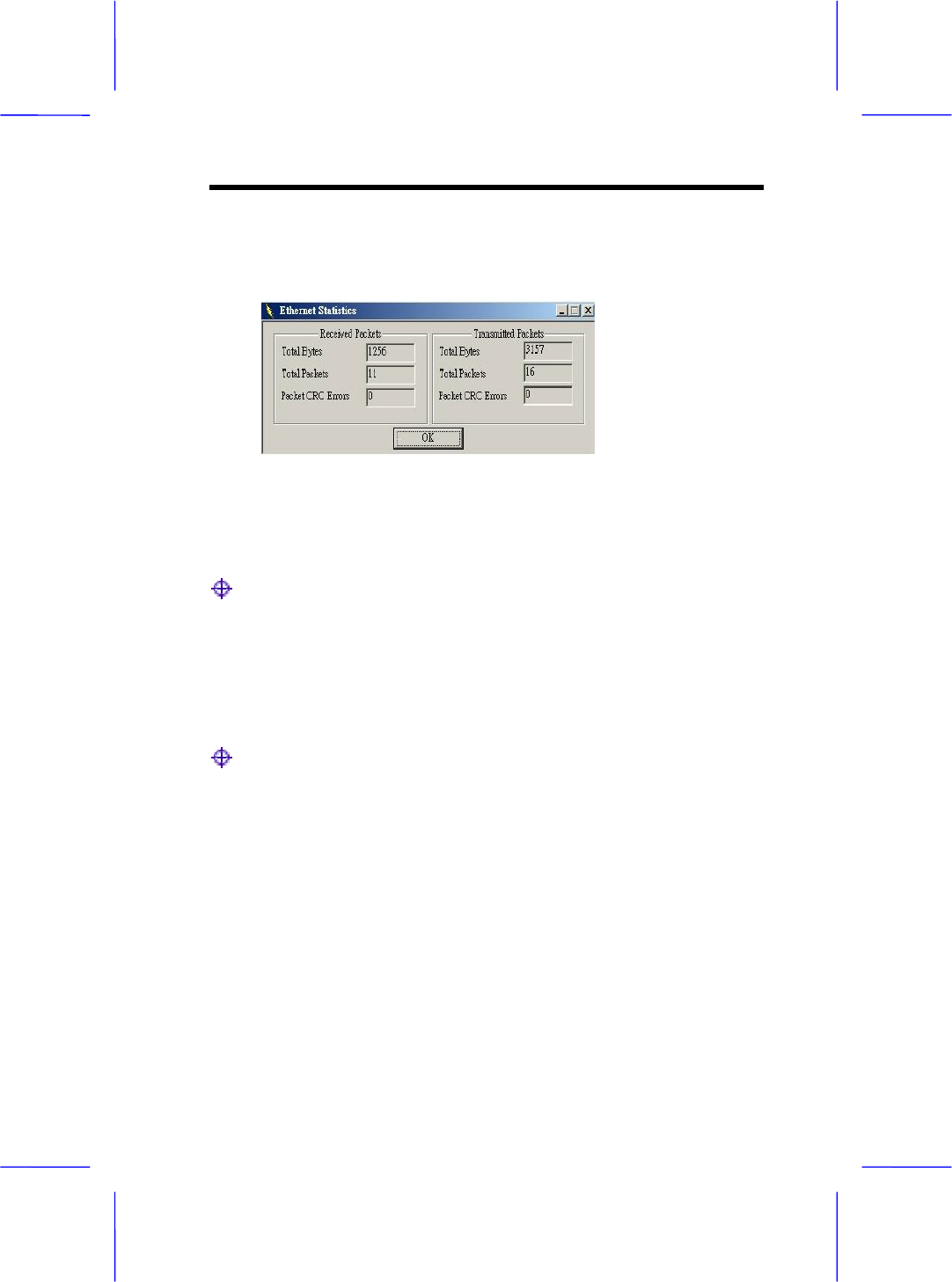
● Ethernet statistics: This submenu reports the statistics concerning
the unit’s Ethernet port activity. The meaning of the fields, concerning
all the statistics is given in the following table.
Network menu: Provides information about the Network. Under
this menu there is only the Associated Station submenu.
Network ->Associated stations
● Associated stations – Using this submenu you can view the MAC
Address of the Associated stations with the Access Point.
Window menu: Under this menu there are the following
submenus
Window ->Cascade or Tile
● Cascade – All opened windows are arranged on the desktop in a
cascade fashion.
● Tile – All open windows are visible on the desktop.
Help menu: Provides on line help about the application.

Chapter
4
Troubleshooting
Trobleshooting 4-1
This chapter gives tips on how to configure the communication
software. This chapter provides solutions to problems usually
encountered during the installation and operation of the Wireless
Network Access Point. Read the description below to solve your
problems.
4.1 Frequently Asked Questions
Can I run an application from a remote computer over the wireless
network?
This will depend on whether or not the application is designed to be
used over a network. Consult the application’s user guide to determine
if it supports operation over a network.
Can, I play computer games with other members of the cordless
network?
Yes, as long as the game supports multiple plays over a LAN (local
area network).Refer to the game’s user guide for more information.
What is the IEEE 802.11b standard?
The IEEE 802.11b Wireless LAN standards subcommittee, which is
formulating a standard for the industry. The objective is to enable
wireless LAN hardware from different manufactures to communicate.
What IEEE 802.11 feature are supported?

4-2 User Manual
The product supports the following IEEE 802.11 functions:
• CSMA/CA plus Acknowledge protocol
• Multi-Channel Roaming
• Automatic Rate Selection
• RTS/CTS feature
• Fragmentation
• Power Management
•
What is Ad-hoc?
An Ad-hoc integrated wireless LAN is a group of computers, each with
a WLAN adapter, Connected as an independent wireless LAN. Ad hoc
wireless LAN is applicable at a departmental scale for a branch or
SOHO operation.
What is Infrastructure?
An integrated wireless and wireless and wired LAN is called an
Infrastructure configuration. Infrastructure is applicable to enterprise
scale for wireless access to central database, or wireless application
for mobile workers.
What is Roaming?
Roaming is the ability of a portable computer user to communicate
continuously while moving freely throughout an area greater than that
covered by a single Wireless Network Access Point. Before using the
roaming function, the workstation must make sure that it is the same
channel number with the Wireless Network Access Point of dedicated
coverage area.

Troubleshooting 4-3
To achieve true seamless connectivity, the wireless LAN must
incorporate a number of different functions. Each node and Wireless
Network Access Point, for example, must always acknowledge receipt
of each message. Each node must maintain contact with the wireless
network even when not actually transmitting data. Achieving these
functions simultaneously requires a dynamic RF networking technology
that links Wireless Network Access Points and nodes. In such a
system, the user’s end node undertakes a search for the best possible
access to the system. First, it evaluates such factors as signal strength
and quality, as well as the message load currently being carried by
each Wireless Network Access Point and the distance of each Wireless
Network Access Point to the wired backbone. Based on that
information, the node next selects the right Wireless Network Access
Points and registers its address. Communications between end node
and host computer can then transmitted up and down the backbone.
As the user moves on, the end nodes RF transmitter regularly checks
the system to determine whether it is in touch with the original or
Wireless Network Access Point whether it should seek a new one.
When a node no longer receives acknowledgment from its original
Wireless Network Access Point, it undertakes a new search. Upon
finding a new Wireless Network Access Point, it then re-registers, and
the communication process continues.
What is BSS ID?
A specific Ad hoc LAN is called a Basic Service Set (BSS). Computers
in a BSS must be configured with the same BSS ID.
What is ESS ID?
An Infrastructure configuration could also support roaming capability
for mobile workers. More than one BSS can be configured as an
Extended Service Set (ESS).Users within an ESS could Roam freely
between BSSs while served as a continuous connection to the network
wireless stations and Wireless Network Access Points within an ESS
must be configured with the same ESS ID and the same radio channel.
What is ISM band?

4-4 User Manual
The FCC and their counterpart outside of the U.S. have set aside
bandwidth for unlicensed use in the ISM (Industrial, Scientific and
Medical) band. Spectrum in the Vicinity of 2.4 GHz, in particular, is
being made available worldwide. This presents a truly revolutionary
opportunity to place convenient high speed wireless capabilities in the
hands of users around the globe.
What is Spread Spectrum?
Spread Spectrum technology is a wideband radio frequency technique
developed by the military for use in reliable, secure, mission-critical
communication systems. It is designed to trade off bandwidth efficiency
for reliability, integrity, and security. In other words, more bandwidth is
consumed than in the case of narrowband transmission , but the trade
off produces a signal that is, in effect, louder and thus easier to detect,
provided that the receiver knows the parameters of the
spread-spectrum signal being broadcast. If a receiver is not tuned to
the right frequency, a spread –spectrum signal looks like background
noise. There are two main alternatives, Direct Sequence Spread
Spectrum (DSSS) and Frequency Hopping Spread Spectrum (FHSS).
What is DSSS?What is FHSS?And what are their differences?
Frequency-hopping spread-spectrum (FHSS) uses a narrowband
carrier that changes frequency in a pattern that is known to both
transmitter and receiver. Properly synchronized, the net effect is to
maintain a single logical channel. To an unintended receiver, FHSS
appears to be short-duration impulse noise. Direct-sequence
spread-spectrum (DSSS) generates a redundant bit pattern for each bit
to be transmitted.This bit pattern is called a chip (or chipping code). The
longer the chip, the greater the probability that the original data can be
recovered. Even if one or more bits in the chip are damaged during
transmission, statistical techniques embedded in the radio can recover
the original data without-the need for retransmission. To an unintended
receiver, DSSS appears as low power wideband noise and is rejected
(ignored) by most narrowband receivers.
Would the information be intercepted while transmitting on air?

Troubleshooting 4-5
WLAN features two-fold protection in security. On the hardware side,
as with Direct Sequence Spread Spectrum technology, it has the
inherent security feature of scrambling. On the software side, WLAN
series offer the encryption function (WEP) to enhance security and
Access Control. Users can set it up depending upon their needs.
Can Wireless products support printer sharing?
Wireless products perform the same function as LAN products.
Therefore, Wireless products can work with Netware, Windows
NT/2000, or other LAN operating systems to support printer or file
sharing.
What is WEP?
WEP is Wired Equivalent Privacy, a data privacy mechanism based on
a 40 bit shared key algorithm, as described in the IEEE 802 .11
standard.

Chapter
5
Appendix
Appendix 5-1
MAC Address
The MAC Address of the AP. Unique 48-bit, hard-coded Media Access
Control address known as the station identifier.
Regulatory domain
You need to select the Regulation Domain among the following
options, FCC, ETSI, SPAIN, DOC, SPAIN, FRANCE and MKK.
Ethernet IP Address
The IP Address of the AP. Network-assigned Internet protocol address
of the Access Point.
Ethernet Subnet Mask
The Ethernet station and the Access Point must be on the same
subnet. The IP address for the Access Point must correspond to the
Subnet Mask. Subnet Mask consists of four sets of three digits that
divides a network into subnetworks.
ESSID
Select the ESSID to be used. The ESSID (up to 32 printable ASCII
characters) of the unit is a string used to identify a WLAN. The ID
prevents the unintentional merging of two co-located WLANs.
ESSID Length
The length of the ESSID (number of characters).

5-2 User Manual
Auto Rate Fall Back
Select Enable or Disable. When this is enabled the transmission rate is
defined by the past transmission status.
Wireless Channel
Select the channel to be used. The channels differ from country to
country. There are 14 channels available.
WEP Key
The WEP key if the WEP option is enabled in order to activate WEP
encryption for transmissions between the stations and the Access
Point.
WEP Type
The Wired Equivalent Privacy Algorithm (64 or 128 bits)
Wireless Fragmentation Threshold
The size at which packets will be fragmented . Choose a setting within
a range of 256 to 2346 bytes. This is the option for the Fragmentation
Threshold activation.
Wireless RTS Threshold
Minimum packet size to require an RTS (Request To Send). For
packets smaller than this threshold, an RTS is not sent and the packet
is transmitted directly to the WLAN. This is the option for the RTS
Threshold activation.
WEP Keys#1-#4-
The default key that will be used. May be edited only if WEP type is 64
bits.
Preamble Type

Appendix 5-3
Select Short or Long Preamble Type. Preamble is the first sub field of
PPDU, which is the appropriate frame format for transmission to PHY
(Physical layer).There are two options, Short Preamble and Long
Preamble. The Short Preamble option improves throughput
performance.
Authentication Type
Select Open System or Shared Key Authentication Type
Open System- With this setting any station in the WLAN can associate
with an Access Point and receive and transmit data (null
authentication).
Shared Key- With this setting only stations using a shared key
encryption identified by the Access Point are allowed to associate with
it.
Both- With this setting stations communicate with or without data
encryption.
Operational Rate Set
By default the unit adaptively selects the highest possible ate for
transmission. In case of obstacles or interference, the system will step
down. Select the basic rates to be used among the following options 1 -
2 (Mpbs), 1 - 2 - 5.5 - 11 (Mbps). Select the Operational Rate set
among the following options, 82 84 8B 96 (1 – 2 - 5.5 - 11 Mbps) or 82
84 0B 16 (1 - 2 Mbps).
Beacon Period
Set the Beacon Period parameter, which specifies the duration
between the range 20-1000 with a typical value of 100.
DTIM
Set the DTIM period. Determines at which interval the AP will send its
broadcast traffic. Default value is 4 beacons.

5-4 User Manual
Receive Antenna
Set the Receive Antenna among the following options Left, Right or
Diversity, to determine which antennas are used for reception.
Transmit Antenna
Set the Transmit Antenna among the following options Left, Right or
Diversity, to determine which antennas are used for transmission.
Operational Mode
Set one of the following operational modes on the Access Point
Access Point
Access Point Client
Wireless Bridge
User Community
Indicates the user’s password. The default password is “public”
User Access
Indicates the user’s access rights. The user can only read and not set
or change the AP’s parameters.
Administrator Community
Indicates the administrator’s password. The default password is
“public”.
Administrator Access
Indicates the Administrator’s access rights. The administrator can read
and also set or save changes to the AP’s parameters.

Appendix 5-5
Manufacturer Community
Indicates the manufacturer’s password.
Manufacturer Access
Indicates the manufacturer’s access rights. The manufacturer can read
and set or save changes to the AP’s parameters. Also can view or
modify the Hardware Configuration.
Gateway IP Address
Network Gateway
IP Filtering
Enable/Disable the possibility to allow only IP protocol packets to pass
through the WLAN and any other protocol packets filtered out.
DHCP client
Enable/Disable automatic IP address assignment by the DHCP server
Primary Port: Determines the Access Point’s MAC and IP Address.
Primary Port
The interface which determines the DHCP server ( Ethernet Port/
Wireless Port).
Authorization Algorithm
Enable/Disable the association with authorized MAC Addresses
stations.
SNMP traps
Enabled/Disabled SNMP traps, which are the messages indicating the
actions related to the AP that have taken place.

5-6 User Manual
Preferred BSSID
Remote MAC Address for connection, in Access Point Client or
Wireless Bridge Operational modes.
WEP 128 keys #1-#4
The default key that will be used. May be edited if WEP type is 128 bits.
ESSID: It is an ASCII string up to 21 characters used to identify a
WLAN that prevents the unintentional merging of two co-located
WLANs. The ESSID value must be the same in all stations and Access
point in the extended WLAN. Select the ESSID to be used.
Channel: There are 14 channels available. The channels differ from
country to country. Select the channel to be used.
Fragmentation threshold: The size at which packets will be
fragmented. Choose a setting within a range of 256 to 2346 bytes.
RTS Threshold: Minimum packet size to require an RTS (Request To
Send). For packets smaller than this threshold, an RTS is not sent and
the packet is transmitted directly to the WLAN. This is the option for the
RTS Threshold activation.
Authentication Type: Select Open System, Shared Key, or Both
Open System: With this setting any station in the WLAN can
associate with an Access Point and receive and transmitted data
(null authentication).
Shared Key: With this setting only stations using a shared key
encryption identified by the Access Point are allowed to associate
with it.
Both: with this setting stations communicate with the Access
Point either with or without data encryption.

Appendix 5-7
Preamble Type (Short/Long): Preamble is the first sub field of PPDU,
which is the appropriate frame format for transmission to PHY (Physical
layer). There are two options, Short Preamble and Long Preamble. The
Short Preamble option improves throughput performance
Rate: By default the unit adoptively selects the highest possible rate for
transmission. Select the basic rates to be used among the following
options 1-2-5.5-11 (Mbps).
Auto Rate Fall Back: When this is enabled the transmission rate is the
optimum rate. In case of obstacles or interference, the system will
automatically fall back.
Regulatory Domain: The value of this field is already set and cannot
be modified.