Prime Electronics and Satellitics WA222M Wireless LAN AP User Manual wa222m
Prime Electronics & Satellitics Inc. Wireless LAN AP wa222m
UserManual.wiki
>
Prime Electronics and Satellitics
>
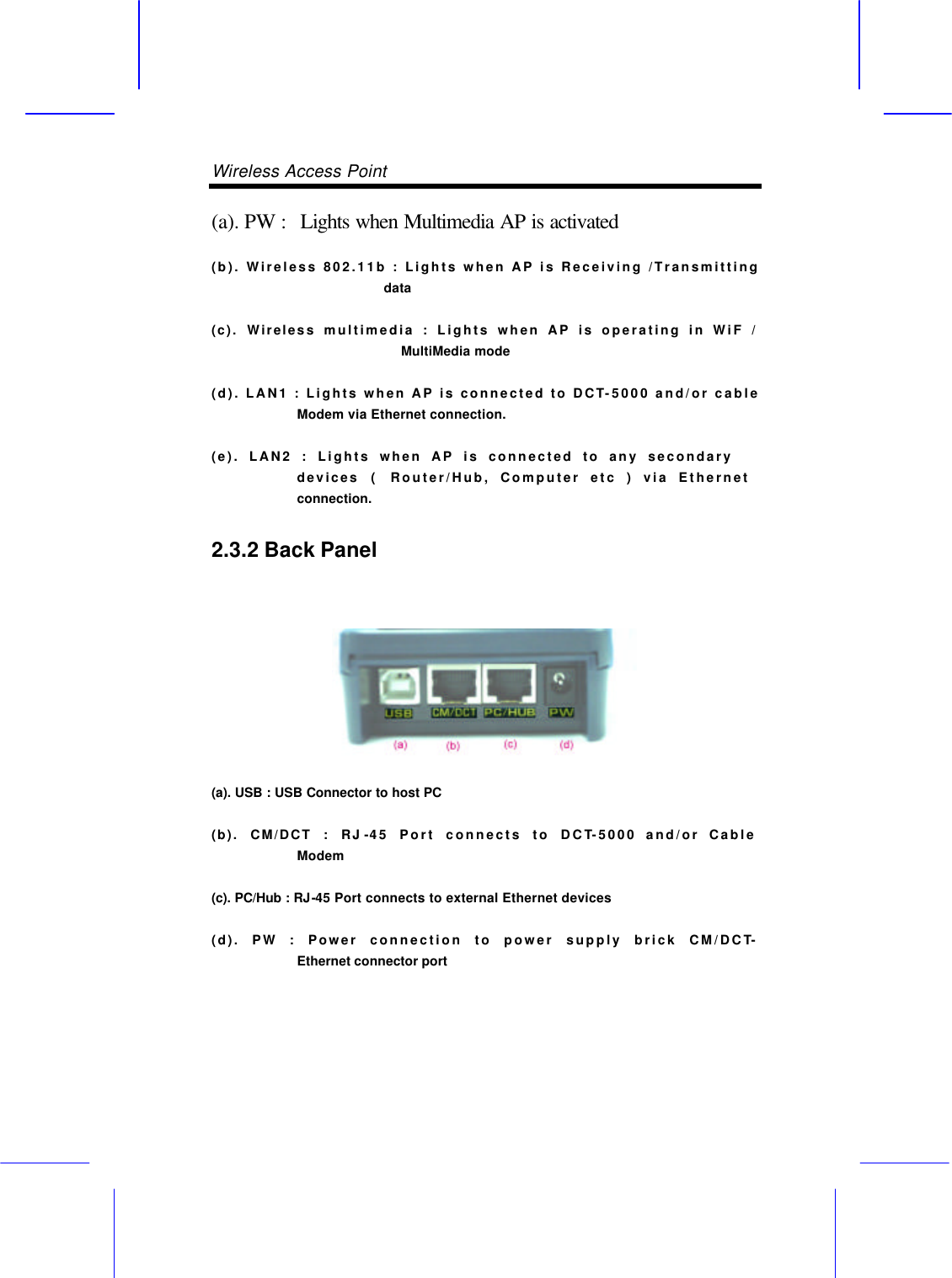
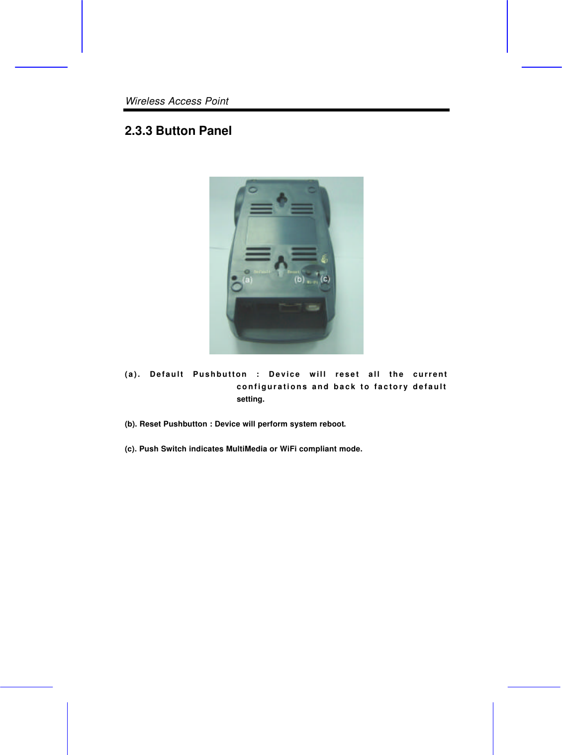
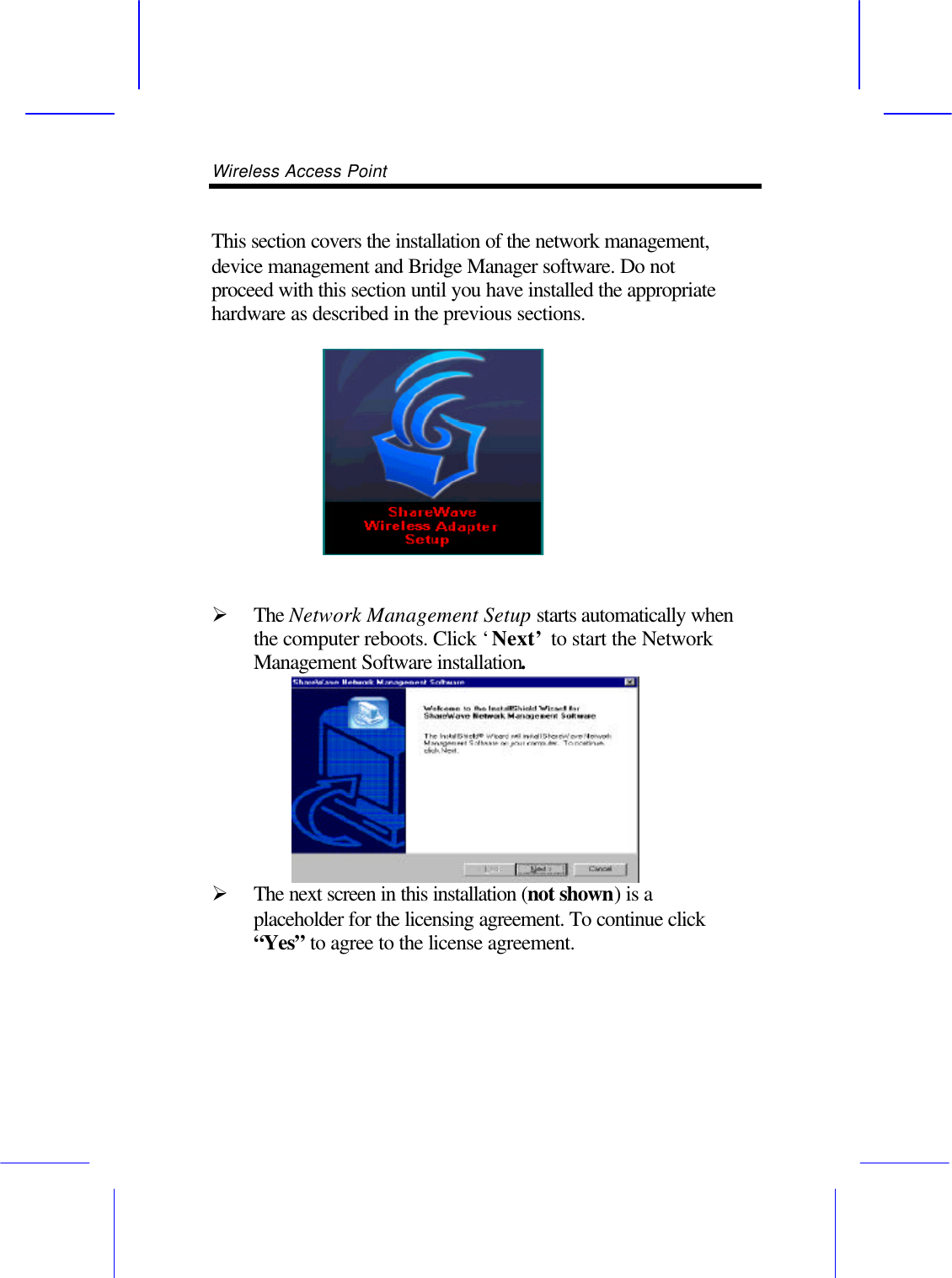
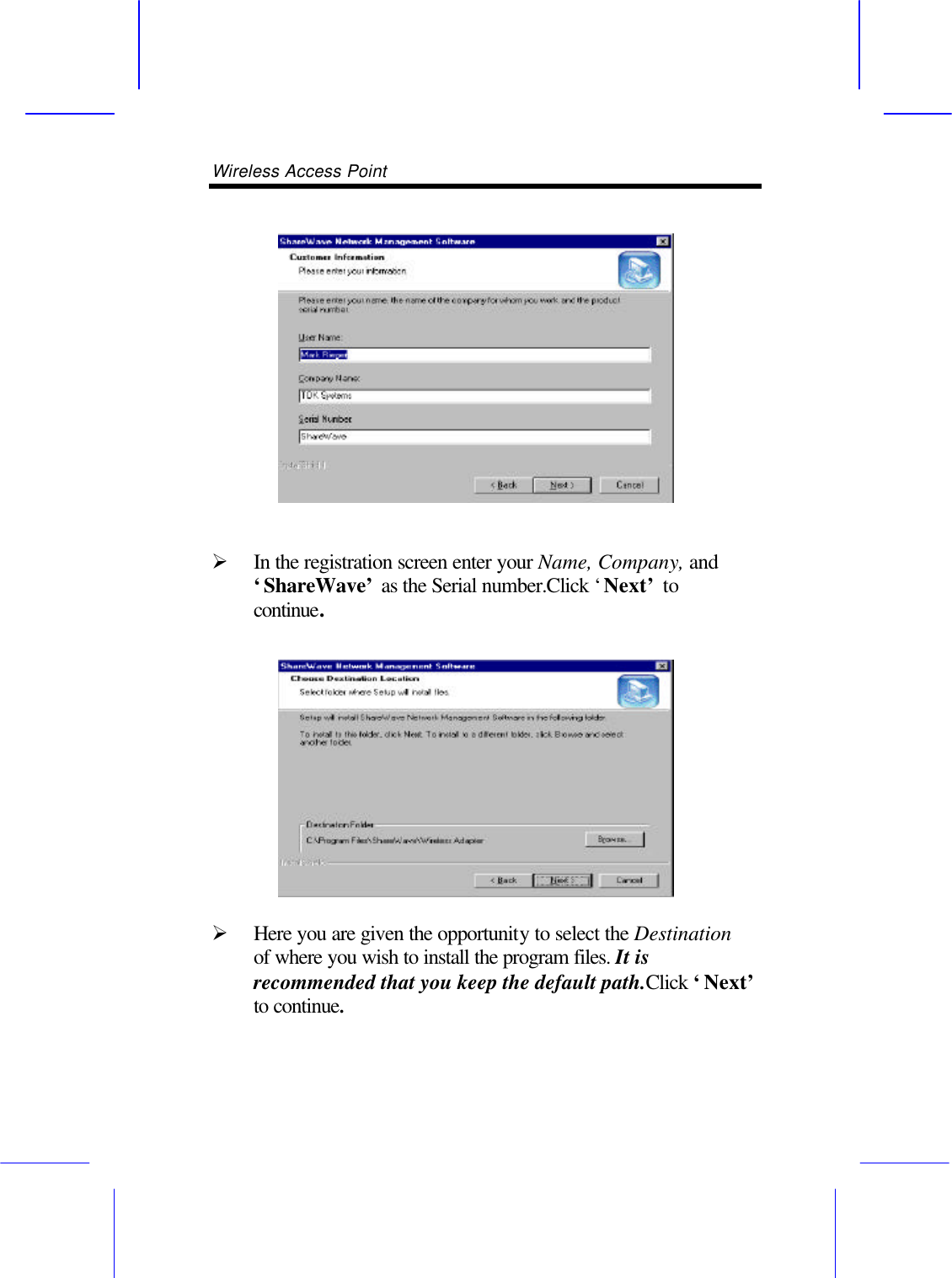
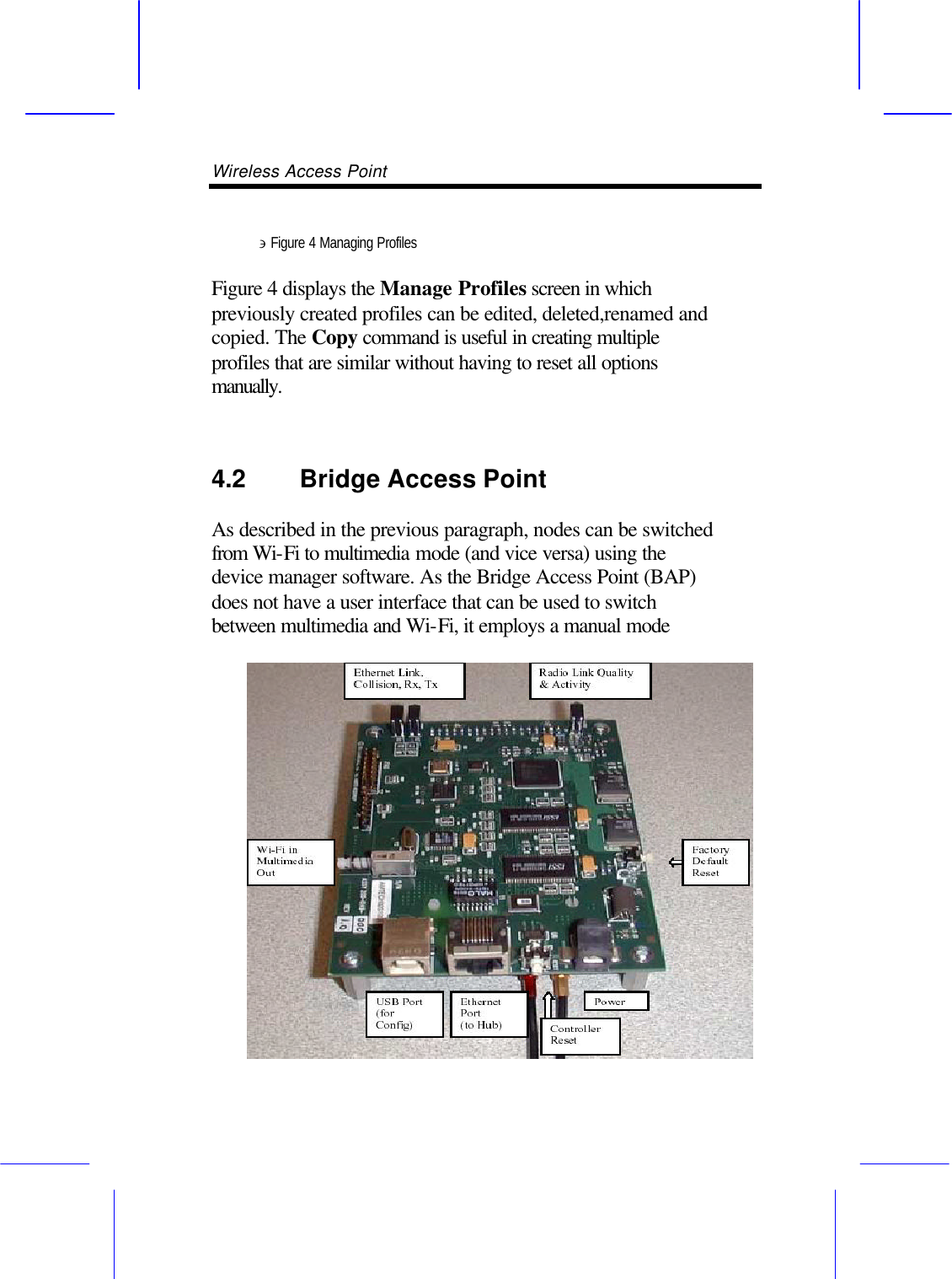
WA222M User Manual
Users Manual
Navigation menu
Upload a User Manual
Namespaces
Wiki Guide
HTML
PDF
Info
Views
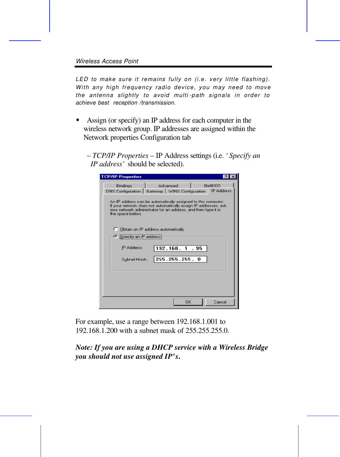
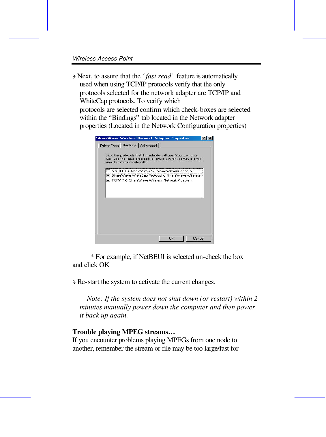
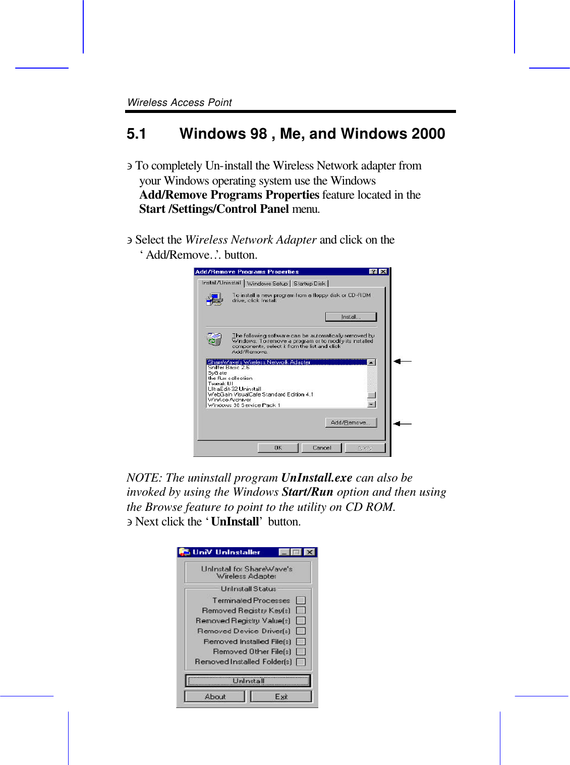
User Manual
Discussion / Help
Navigation