Prime Electronics and Satellitics WA222M Wireless LAN AP User Manual wa222m
Prime Electronics & Satellitics Inc. Wireless LAN AP wa222m
Users Manual

Wireless Multimedia LAN
Access Point
User Manual
P/N:3010WA222M01
Copyright
Copyright 2001 by this company. All rights reserved.
No part of this publication may be reproduced, transmitted,
transcribed, stored in a retrieval system, or translated into any
language or computer language, in any form or by any means,

Wireless Access Point
electronic, mechanical, magnetic, optical, chemical, manual or
otherwise, without the prior written permission of this company.
This company makes no representations or warranties, either
expressed or implied, with respect to the contents hereof and
specifically disclaims any warranties, merchantability or fitness
for any particular purpose. Any software described in this
manual is sold or licensed "as is". Should the programs prove
defective following their purchase, the buyer (and not this
company, its distributor, or its dealer) assumes the entire cost of
all necessary servicing, repair, and any incidental or
consequential damages resulting from any defect in the software.
Further, this company reserves the right to revise this
publication and to make changes from time to time in the
contents hereof without obligation to notify any person of such
revision or changes.
.
All brand and product names mentioned in this manual are trademarks and/or registered
trademarks of their respective holders.
Federal Communication Commission
Interference Statement
This equipment has been tested and found to comply with the

Wireless Access Point
limits for a Class B digital device, pursuant to Part 15 of FCC
Rules. These limits are designed to provide reasonable
protection against harmful interference in a residential
installation. This equipment generates, uses, and can radiate
radio frequency energy and, if not installed and used in
accordance with the instructions, may cause harmful
interference to radio communications. However, there is no
guarantee that interference will not occur in a particular
installation. If this equipment does cause harmful interference
to radio or television reception, which can be determined by
turning the equipment off and on, the user is encouraged to try
to correct the interference by one or more of the following
measures:
1. Reorient or relocate the receiving antenna.
2. Increase the separation between the equipment and receiver.
3. Connect the equipment into an outlet on a circuit different from
that to which the receiver is connected.
4. Consult the dealer or an experienced radio technician for help.
FCC Caution: To assure continued compliance.(example-use only shielded
interface cables when connecting to computer or peripheral devices). Any changes or
modifications not expressly approved by the party responsible for compliance could
void the user’s authority to operate the equipment.
This device complies with Part 15 of the FCC Rules. Operation is subject to the
Following two conditions: ( 1 ) This device may not cause harmful interference, and
( 2 ) this Device must accept any interference received, including interference that
may cause undesired operation.

Wireless Access Point
Federal Communication Commission (FCC ) Radiation Exposure
Statement
This equipment complies with FCC radiation exposure set forth
for an uncontrolled environment. In order to avoid the
possibility of exceeding the FCC radio frequency exposure
limits, human proximity to the antenna shall not be less than 20
cm(8 inches) during normal operation.
R&TTE Compliance Statement
This equipment complies with all the requirements of DIRECTIVE
1999/5/CE OF THE EUROPEAN PARLIAMENT AND THE COUNCIL
OF 9 March 1999 on radio equipment and telecommunication terminal
Equipment and the mutual recognition of their conformity ( R&TTE)
The R&TTE Directive repeals and replaces in the directive
98/13/EEC(Telecommunications Terminal Equipment and Satellite
Earth Station Equipment) As of April 8,2000.
Safety
This equipment is designed with the utmost care for the safety of those
who install and use it. However , special attention must be paid to the
dangers of electric shock and static electricity when working with
electrical equipment. All guidelines of this and of the computer
manufacture must therefore be allowed at all times to ensure the safe
use of the equipment.
EU Countries Not Intended for Use
The ETSI version of this device is intended for home and office
use in Austria Belgium, Denmark , Finland , France ( with
Frequency channel restrictions). Germany ,Greece, Ireland ,
Italy , Luxembourg .The Netherlands, Portugal , Spain , Sweden
and United Kingdom.
The ETSI version of this device is also authorized for use in
EFTA member states Iceland, Liechtenstein, Norway and
Switzerland.

Wireless Access Point
EU Countries Not intended for use
None.
Potential restrictive use
France: Only channels 10,11,12 ,and 13

Wireless Access Point
Chapter 1 Introduction……………………………………1-1
1.1 Package Content………………………………………..1-1
1.2 System
Requirement……………………………………1-1
1.3 Feature……………………………………………………1-2
1.4 Specification………………………………………………1-3
Chapter 2 Installation
2.1 Hardware/OS requiements .................................. 2-1
2.2 Installing the hardware .......................................... 2-1
2.3 Installing the Bridge manager ................................ 2-2
2.4 Access Point/Bridge LED status Indicators……………2-6
Chapter 3 Installing the Network Manager
software …..………………………………………3-1
Chapter 4 Using the Network
4.1 Device Managemet ........................................... 4-1
4.2 Bridge Access Point ............................................ 4-4
4.3 Network Management ......................................... 4-5
4.4 Enrolling a Bridge Access Point into the netwrok .... 4-6
4.5 Adding additional nodes ...................................... 4-7
4.6 Bridge Manager .................................................. 4-8
4.7 Using WEP ........................................................ 4-9
4.8 Tip on using the Network ....................................4-10

Wireless Access Point
Chapter 5 Uninstall
5.1 Windows 98,Me,and Windows 2000……………………5-1

Wireless Access Point
Thank you for purchasing the Wireless Multimedia Access
Point/Bridge. It offered a unprecedented multimedia wireless
solution and provided the simultaneous multimedia audio and
video stream without any other network activity. You may use
the device to extends Cable/DSL connection and existing
Ethernet network without any wires. This manual guides you on
how to install and properly use the Wireless Access Point in
order to take full advantage of its features.
1.1 Package Contents
Make sure that you have the following items:
• One Wireless Access Point
• One AC Power Adapter
• One USB Cable
• One Quick Installation Guide
• One CD-Title with AP manager Software
If any of the above items are missing, contact your supplier as soon as
possible.
1.2 System Requirements
Before installation, please check the following requirements with your
equipment.
• Pentium Based ( And Above ) IBM-Compatible PC System
• CD-ROM drive
• One Available USB Connector
• Windows 9x/ME/NT4.0/2000 Operating System with TCP/IP
protocol

Wireless Access Point
1.3 Features
∗ Wi-Fi (IEEE 802.11b) Certification and Interoperability with
Wireless LAN Standards
∗ IEEE 8021.b & 802.11e-class Compliant
∗ Contention-Free Access and Dynamic Stream Support
∗ Parameterized Quality of Service (QoS) to Support Multimedia
Distribution and Ensure Delivery of Isochronously /
Time-Dependent Content
∗ Excellent Interference Immunity
∗ Peer-to-Peer Communication among Multiple Devices for
Efficient Bandwidth Utilization.
∗ Forward Error Correction to Repair Corrupted Packets “ On The
Fly ” during Transmission
∗ Channel Agility to Avoid In-Band Interference from Household
Appliances, such as Microwave Ovens and Cordless Phones
∗ Better Range and Fade Margin for Coverage throughout The
Home
∗ Open Enrollment for Easily Adding Devices to The Network
∗ Coordinator Redundancy to Prevent Single Point of Failure
∗ Delayed Acknowledgement Improves Payload Efficiency and
Minimizes Overhead for Network Access
∗ Easy Configuration and Set Up
1.4 Specification
•
Standard Wi-Fi (IEEE802.11b) and QoS
•
( IEEE802.11e-class)
•
Signal Type DSSS (Direct Sequence Spread
Spectrum)
•
Modulation QPSK / BPSK / CCK
•
Port Two RJ 45 / One USB
•
Ethernet Interface IEEE802.3 10 BASET
•
Antenna Patch Antenna
•
Data Encryption 40 bit WEP encryption ,

Wireless Access Point
128 bit KEY Length(otional)
•
Frequency 2.4GHz –2.4835GHz
•
Channel 11 Channels(US,Canada)
13 Channels(Europe)
14 Channel(Japan)
•
Data Rate Up to 11Mbps(with automatic scale back)
•
Transmit Power Guaranteed 20 dBm , Typically 22 dBm
•
Receive Sensitively Guaranteed –83 dBm ,
Typically –85 dBm
LED Indicators Power, Radio Activity, WiFi
compliant or Multimedia , RJ45-1,
RJ45-2
Power Input-AC 100-240V , 47-63Hz, 0.3A
Output-DC 5V/
2A
•
Temperature Operating :0℃ to 40℃,
Storage : -20℃ to 70℃,
•
Humidity 95% Non-Condensing
•
Dimensions 163*89*55mm

Wireless Access Point
Before you proceed with the installation, it is necessary that you
have enough information about the Wireless Access point
2.1 Installing the hardware
Perform the following steps to install the Wireless Multimedia
Access Point/Bridge.
Ø If applicable, insert the Ethernet cable into the RJ45
connector on the AP/Bridge to connect to a Hub
Ø Next, apply power to the AP/Bridge by plugging in the
power adapter supplied with the evaluation kit.
Ø This completes the hardware portion of the installation.
The next step is to enroll the AP/Bridge into the wireless
network. Turn to Enrolling a Bridge Access Point into the
network on page 3-1 to continue the installation by using the
Network Management application on a wireless active PC
node to enroll the bridge into the network.
Ø Alternatively read the below section on the installation of
the Bridge manager to manually configure the Access
Point/Bridge. Manual configuration is required to change
AP/Bridge settings including network names, SSID and WEP
settings.
2.2 Installing the Bridge manager
Wireless Access Point
The examples shown reflect a Windows 98 operating system.
The actual installation screens may be slightly different on
Windows 2000 or Millennium.Perform the following steps to
install the wireless adapter. You may need your Windows CD
during the configuration.
The Access Point/Bridge can be manually configured using the
“Bridge manager”. Follow the below instructions to install this
software.
Ø Connect one end of the supplied USB cable to the Access
Point/Bridge and the other end to a computer. The computer
must be Windows 98, 2000 or Millennium based but does not
have to be a node in the network (any network or
non-network PC can be used to run the Bridge Manager
software).
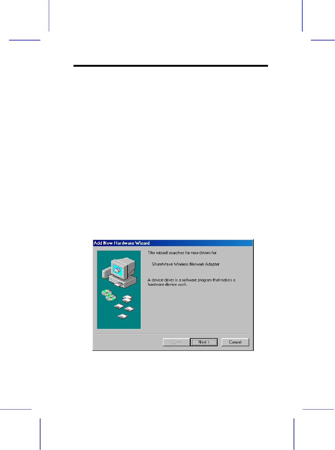
Ø The computer will detect the AP/Bridge and display the
below message.
Wireless Access Point
Ø Insert the installation CD into your CDROM drive and
click “Next.”
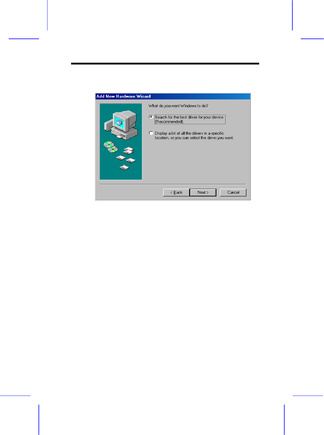
Ø Select “Search for the best driver for your device,” and
click “Next.”
Wireless Access Point
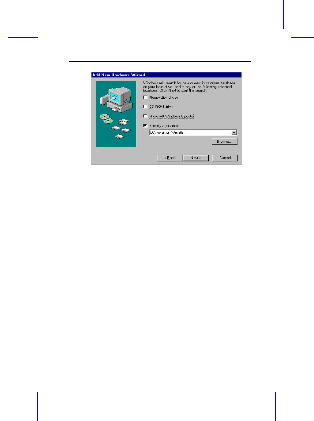
Ø Check only the box that says ‘Specify a location’. Uncheck
the other boxes if any are selected. Use the ‘Browse’
option to find the “Install on Win…” directory located in
the “\BRIDGE” folder on the CD ROM installation disk
(e.g. D:\BRIDGE\Install on Win98 to install the Wireless
Network Adapter on a Windows 98 OS where the CD
ROM drive is designated as the D: drive).Click ‘Next’.
WINDOWS 2000 & MILLENNIUM NOTE: Be sure to browse
to the exact location of the Windows 2000 or MILLENNIUM
drivers. Do not use the automatic search option to locate the
drivers, as it will automatically default to the wrong Windows
driver which will cause installation to fail.
Wireless Access Point
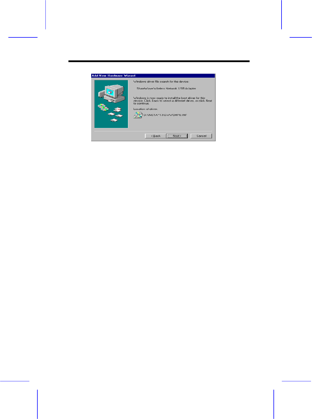
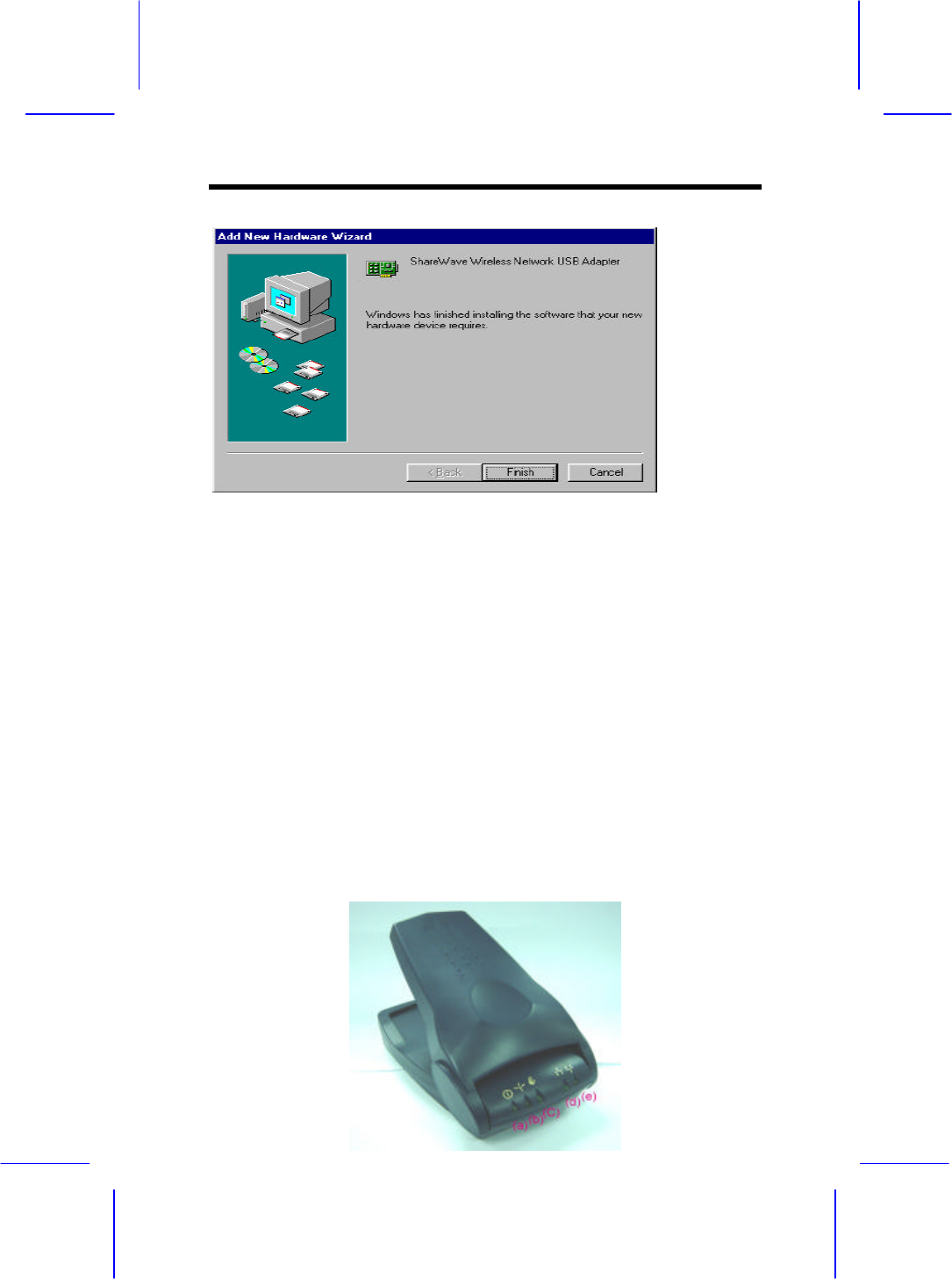
Ø Windows will find the “Wireless Network USB Adapter”
Click “Next.” Windows will find the drivers located on the
CD and begin to install them. Be patient, this can take up to
several minutes.
Ø If your system is not associated to the Windows 98 CAB
files you will be asked for the Windows 98 CD.Remove the
Installation CD and insert the Windows CD into your CD
ROM drive and click ‘OK.’
Ø It may be necessary to enter the drive letter and path
pointing to the Win98 directory; for example “D:\Win98 if
you are installing the card into a Windows 98 system with
the CD-ROM drive designated as the D: drive.
Note: This process can take a few minutes.
Wireless Access Point
Ø When completed click ‘Finish’. You will next be asked to
reboot the computer. Click ‘Yes’.
Note: If the system does not shut down (or restart) within 2
minutes manually power down the computer and
then power it back up again
This completes the hardware driver portion of the installation.
2.3 Indicators
2.3.1 Front Panel
Wireless Access Point
(a). PW : Lights when Multimedia AP is activated
(b). Wireless 802.11b : Lights when AP is Receiving /Transmitting
data
(c). Wireless multimedia : Lights when AP is operating in WiF /
MultiMedia mode
(d). LAN1 : Lights when AP is connected to DCT-5000 and/or cable
Modem via Ethernet connection.
(e). LAN2 : Lights when AP is connected to any secondary
devices ( Router/Hub, Computer etc ) via Ethernet
connection.
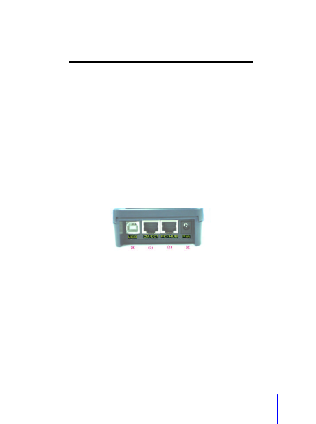
2.3.2 Back Panel
(a). USB : USB Connector to host PC
(b). CM/DCT : RJ -45 Port connects to DCT-5000 and/or Cable
Modem
(c). PC/Hub : RJ-45 Port connects to external Ethernet devices
(d). PW : Power connection to power supply brick CM/DCT-
Ethernet connector port
Wireless Access Point
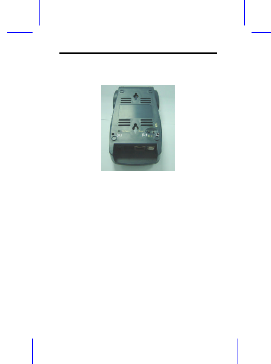
2.3.3 Button Panel
(a). Default Pushbutton : Device will reset all the current
configurations and back to factory default
setting.
(b). Reset Pushbutton : Device will perform system reboot.
(c). Push Switch indicates MultiMedia or WiFi compliant mode.
Wireless Access Point
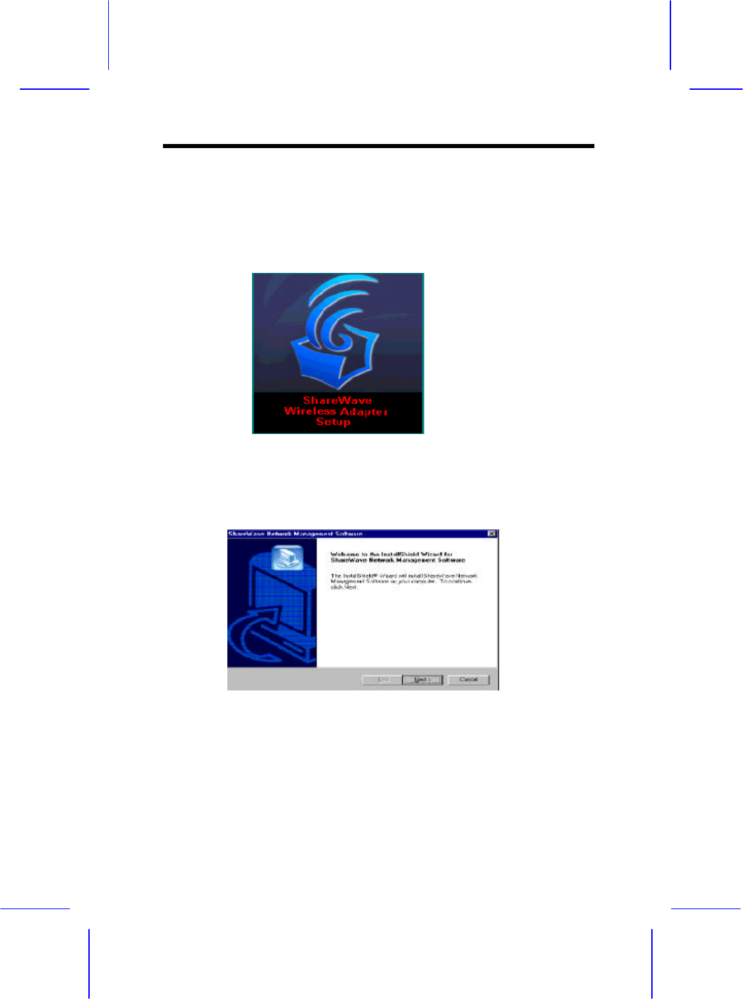
This section covers the installation of the network management,
device management and Bridge Manager software. Do not
proceed with this section until you have installed the appropriate
hardware as described in the previous sections.
Ø The Network Management Setup starts automatically when
the computer reboots. Click ‘Next’ to start the Network
Management Software installation.
Ø The next screen in this installation (not shown) is a
placeholder for the licensing agreement. To continue click
“Yes” to agree to the license agreement.
Wireless Access Point
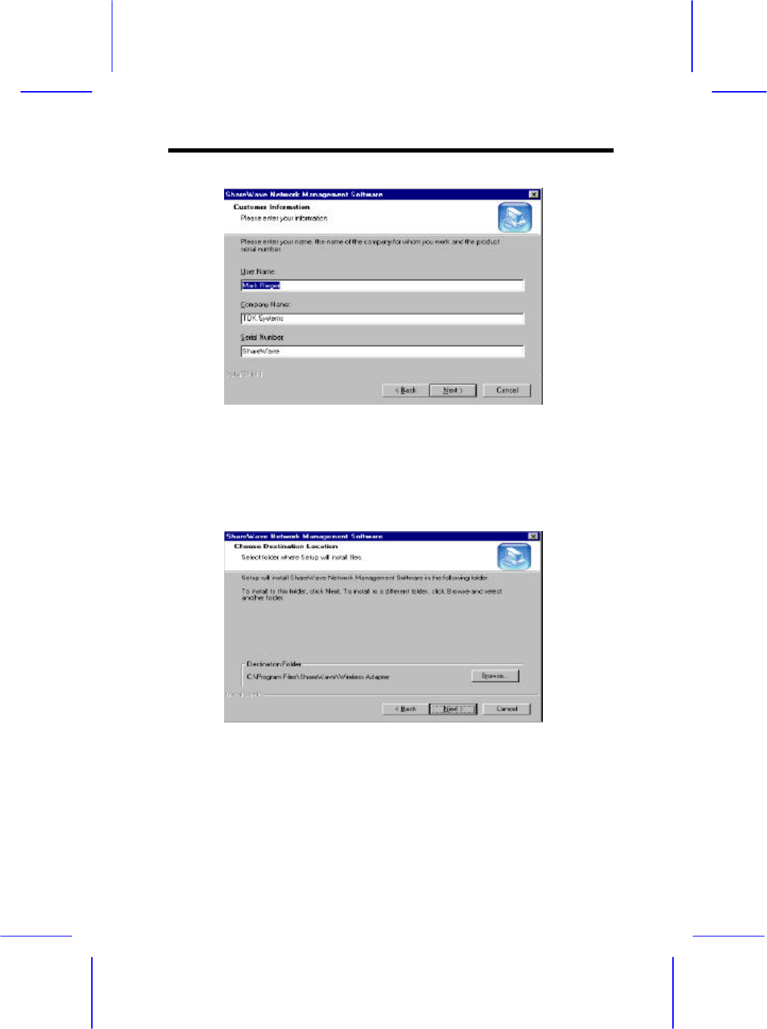
Ø In the registration screen enter your Name, Company, and
‘ShareWave’ as the Serial number.Click ‘Next’ to
continue.
Ø Here you are given the opportunity to select the Destination
of where you wish to install the program files. It is
recommended that you keep the default path.Click ‘Next’
to continue.
Wireless Access Point
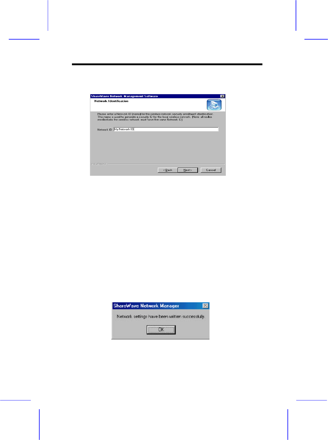
Ø Enter a Network ID (name) for the wireless network
security identification. This name is used to generate a
security ID for enrollment into the local wireless network.
Note: all nodes enrolled into the wireless network must have the
same Network ID Click ‘Next’ to begin the process of installing
the Network Management software.
Ø The below message box will indicate that the system
configuration parameters entered during the installation
have been successfully uploaded to the flash memory. Click
‘OK’.
The installation is now complete.
Wireless Access Point
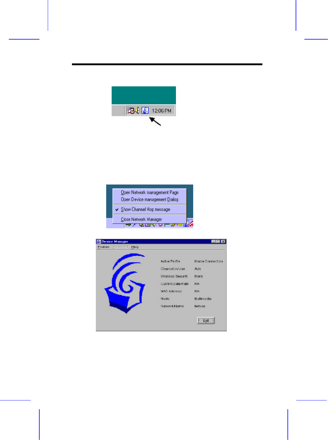
4.1 Device Management
If the icon does not appear in the system tray, double-click the
icon on the desktop.
The icon in the system tray offers additional information by a
right click option ‘Open Device management Dialog’.
• Figure 1 Device Management Application
Wireless Access Point
The Bodega Device Manager introduces the “Profiles” concept.
Profiles allow a user to store specific settings for a particular
situation or environment. A user may have an “Office” profile in
which the node
operates in Wi-Fi mode and a “Home” profile for Multimedia
mode, for instance. Profiles will help the user manage the
appropriate settings including network IDs, WEP, and operating
mode.
Profiles can be created, managed (for editing) and activated
from the Device Manager application by selecting the Profiles
menu.
When creating a new profile from this menu, the software will
ask the user to select either a Wi-Fibased or a Multimedia-based
profile.
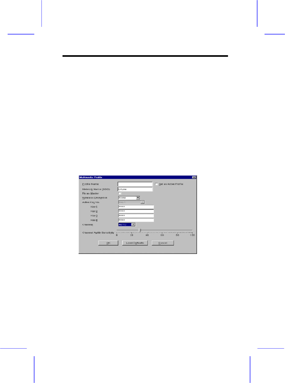
∋ Figure 2 Creating a Multimedia Profile
Figure 2 shows the screen to create a new Multimedia profile.
Both settings that are common between Wi-Fi and Multimedia
mode (such as Profile Name and encryption setting) and any
settings unique to
Wireless Access Point
Multimedia mode can be set here. Unique settings include the
“Auto” setting for the channel selection and the Channel Agility
sensitivity setting (both unique to the Channel Agility feature).
Another Multimedia-only setting is the “Fix as Master” option,
which forces a particular node to be the network coordinator.
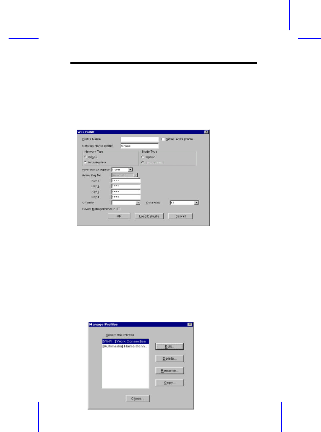
∋ Figure 3 Creating a WiFi Profile
Figure 3 shows the WiFi profile “create” screen. The
WiFi-unique options that can be set on this screen are the
Network and Node type settings in addition to Data Rate and
Power Management settings.
Once two or more profiles are created, the user can switch
between these profiles using the Profiles menu in the main
device manager screen.
Wireless Access Point
∋ Figure 4 Managing Profiles
Figure 4 displays the Manage Profiles screen in which
previously created profiles can be edited, deleted,renamed and
copied. The Copy command is useful in creating multiple
profiles that are similar without having to reset all options
manually.
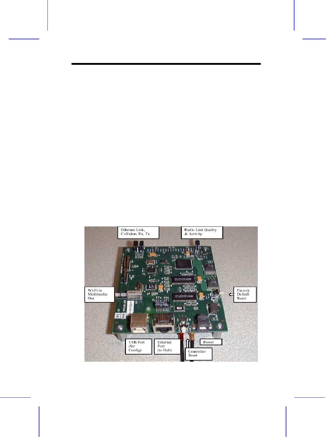
4.2 Bridge Access Point
As described in the previous paragraph, nodes can be switched
from Wi-Fi to multimedia mode (and vice versa) using the
device manager software. As the Bridge Access Point (BAP)
does not have a user interface that can be used to switch
between multimedia and Wi-Fi, it employs a manual mode

Wireless Access Point
switch. This switch can be found on the BAP and is labeled
accordingly.
•
Mode Switch – Used to switch between Multimedia
(WhiteCap) and Wi-Fi mode (Wi-Fi = In; Multimedia = Out)
•
Factory Default Reset – Used to reset all parameters (i.e.
SSID, WEP etc) to the factory default
•
Controller Reset – Used to reset the BAP (similar to power
cycling)
•
Power – Connects to (included) power adapter
•
Ethernet Port – Connects to HUB for LAN / Internet
connectivity
•
USB Port – Connects to connector, use for configuration only
(Bridge Manager software required)
4.3 Network Management
The Network Manager will start automatically once you logon
to Windows. The icon in the Windows Tray will appear when
the Network Management software is running. From this Icon
the earlier described Device Management and network
management application can be started (right-click on the icon).
Note that the Network Management Application is ONLY
available when the Network is in Multimedia mode.
Double clicking on the icon in the system tray brings up the
network management utility in your browser.
Note: This utility requires Microsoft’s Internet Explorer with
Java™ technology enabled. If TCP/IP is not installed, you will
Wireless Access Point
not be able to use network management utilities.
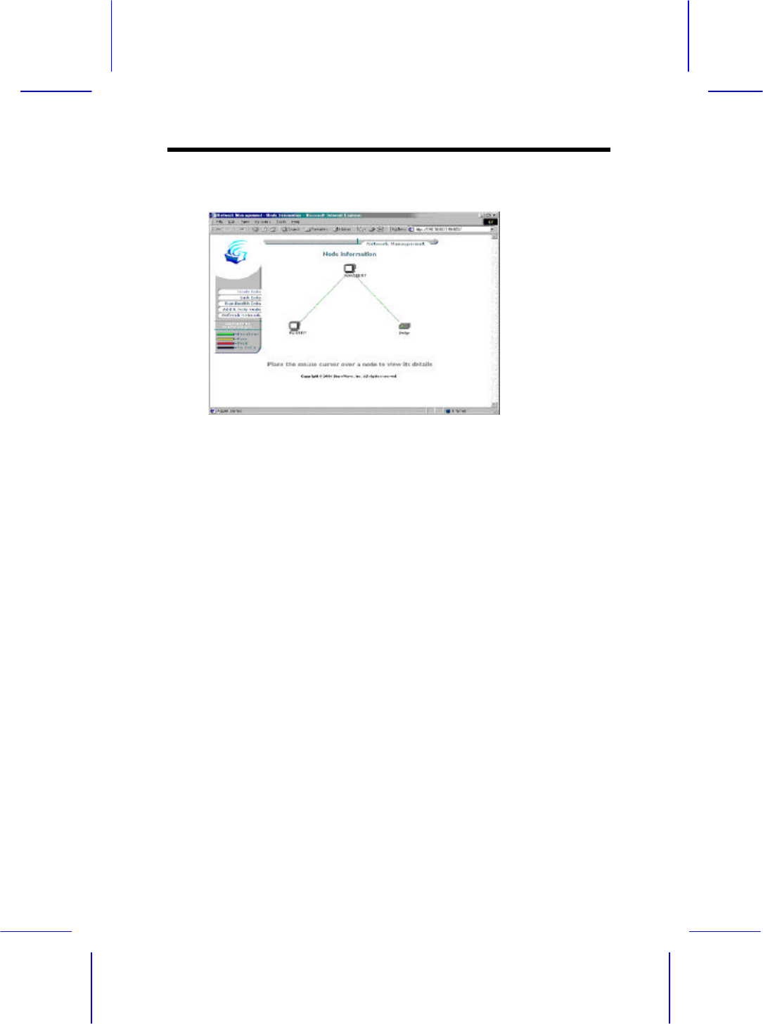
The ‘Node Information’ page in network management utility
displays a diagram of the active Multimedia network. Additional
information is also available by clicking on buttons to the left
side of the page. The Color
legend on the lower left designates the quality of the connection
and is indicated by the color of the lines between any two nodes.
The information on this page is obtained from the Master node
for all nodes on the network. If the Master node is a
non-functional node this HTML page will not be available on
the client nodes and a “troubleshooting page” will be displayed
instead.
4.4 Enrolling a Bridge Access Point into
the network
To add a Bridge node to the network the designated Master node
must allow the Bridge to be “enrolled” into its secured network
group. This “group” is based on the network identification (or
Wireless Access Point
‘Network ID’) entered during installation. If the Network ID of a
node matches the master’s Network ID, the node will be
automatically enrolled into the group.
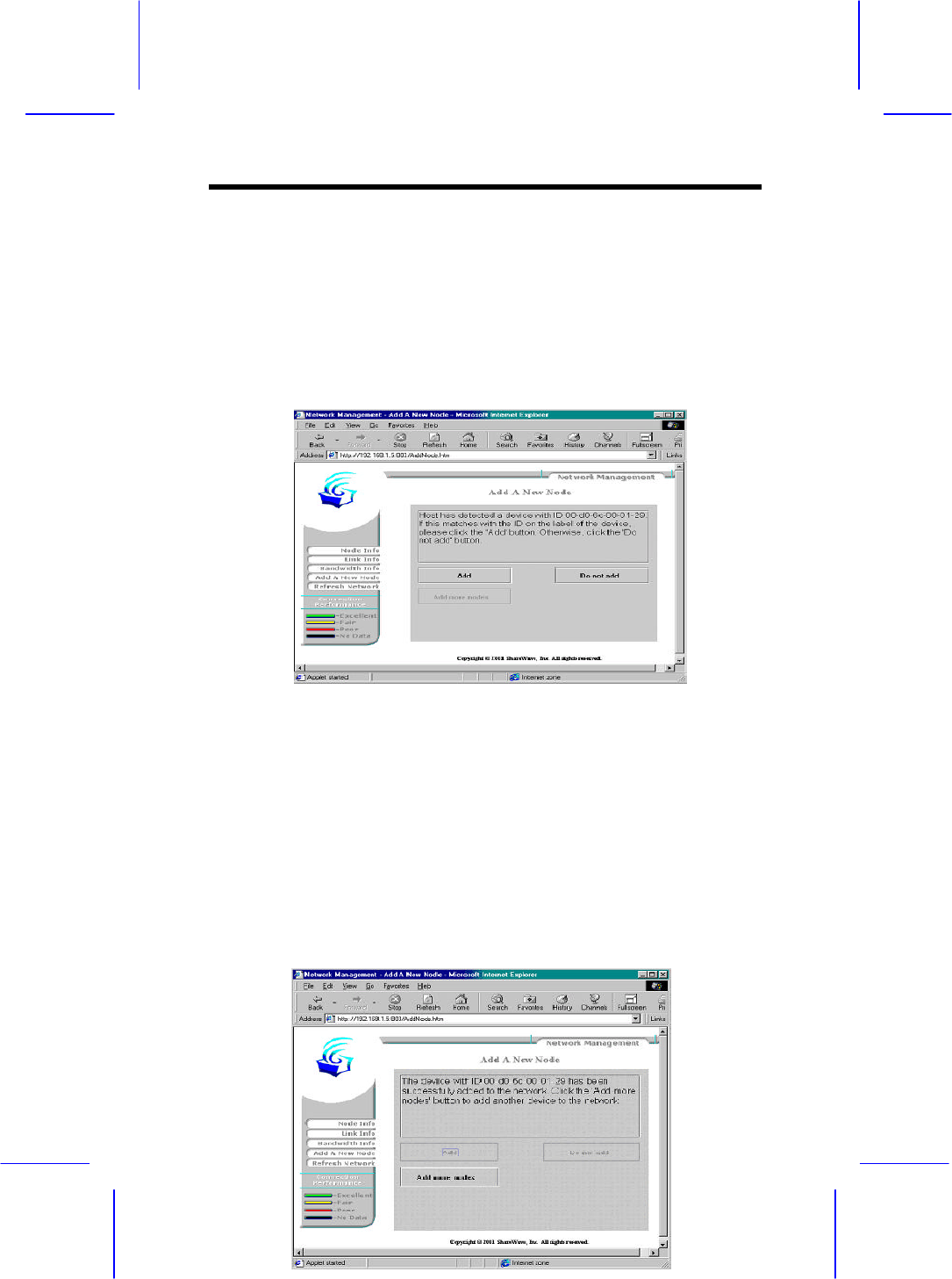
To add a Wireless Bridge to the network or add a new node
which is configured to be in an open enrollment mode, click on
the ‘Add A New Node’ button in the Network Management page
from any node in the system.
The Master node will search for node who have not been added
to the group (those which are determined to be in open
enrollment).
In the example above the Master node has detected a bridge
device with the MAC address of 00-D0-6C-00-01-29.
To add (or enroll) this Bridge into the network click on the
‘Add’ button. The Master node will forward its Network ID to
the Bridge node which as been detected to be in open enrollment

Wireless Access Point
mode.
Refer to paragraph 7.6 for instructions on how to manually
configure the Bridge Access Point. Manual configuration will
give you more control over the BAP settings including network
names, SSID and WEP settings.
4.5 Adding additional nodes
To add a node to the network the designated Master node
(typically the first node installed) must first allow the client to
be enrolled into its secured network group. This group is based
on the wireless network identification (‘Network ID’) entered
during installation. If the Network ID of the client matches the
master’s (typically first node installed) Network ID (name), the
client will automatically be enrolled into the group.
If the clients Network ID does not match the subnet group’s
dentification (i.e. the Network ID assigned to the Master) the
client will not be allowed to enroll into the group. The client’s
network identification (Network ID)
can be changed using the Device Management application.
To reset the Bridge Network ID and place the bridge back into
an ‘open enrollment’ mode press on the ‘Network ID reset’
button on the bridge (see page 11 for button location)
4.6 Bridge Manager
Refer to section for Bridge Manager installation instructions.
Wireless Access Point
Be sure to (re) connect the USB cable. The bridge will now
enter configuration mode. The Bridge manager can be started by
double-clicking the icon on the desktop (use the “Bridge Device
Manager” icon).
Note: While the bridge is in “configuration mode” (when the
USB cable is inserted), the bridge will not function in the
network. Upon removal of the USB cable the Bridge will
assume its normal operation.
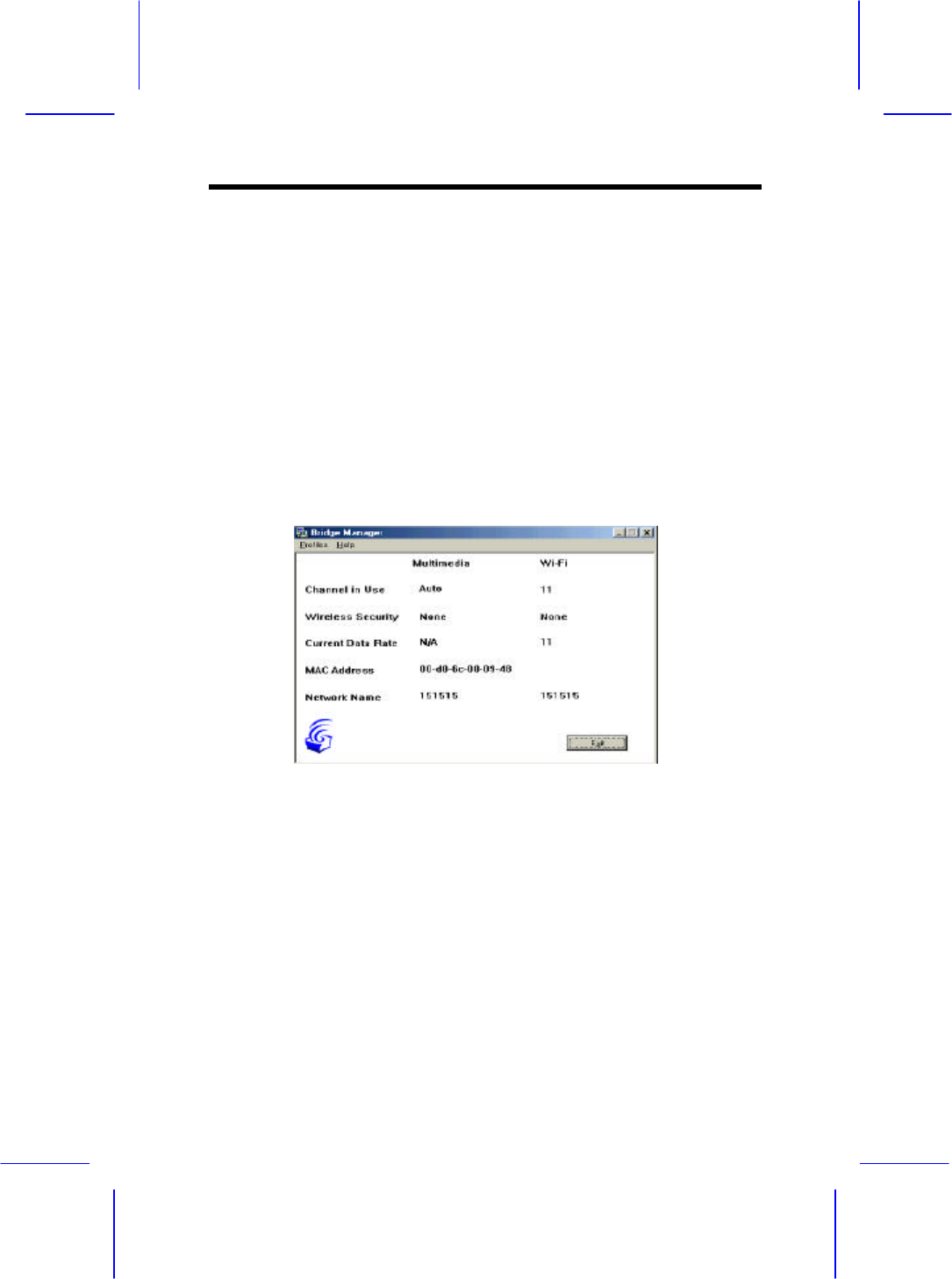
After the application starts, it will display a general information
screen which provides information for the current Multimedia
and Wi-Fi settings.
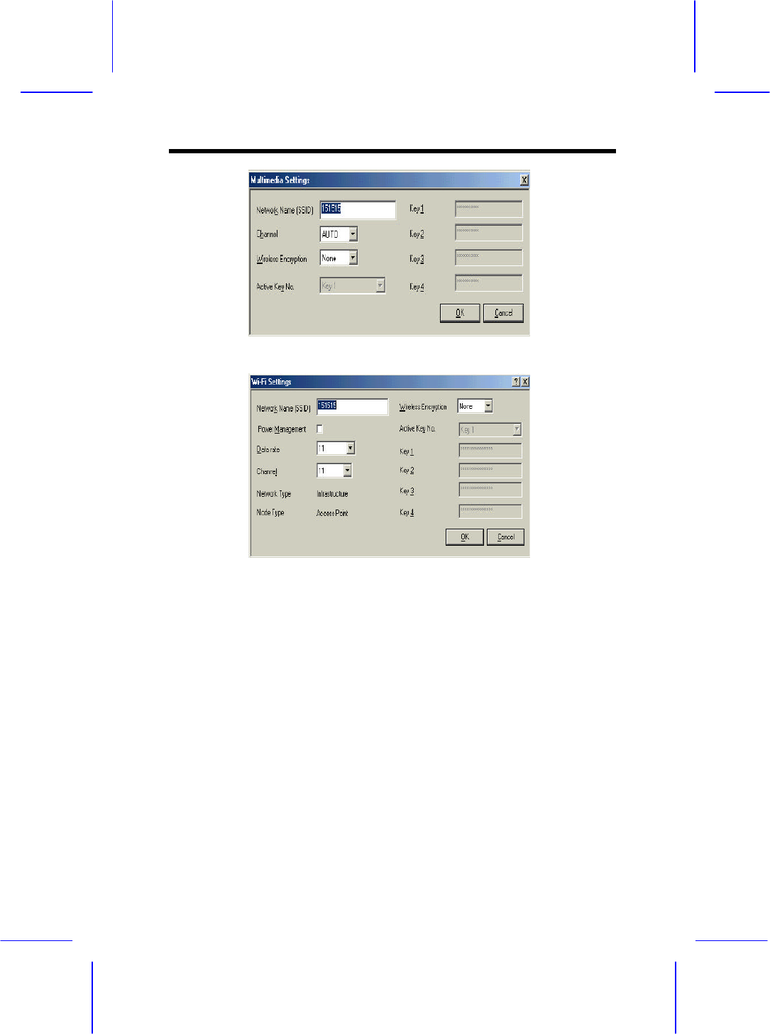
To edit these settings, select either the “Multimedia profile” or
the “Wi-Fi profile. As shown below, all relevant settings for
both Wi-Fi and Multimedia mode can be set or modified. Note
that the separate profiles allow for unique settings (i.e. different
SSID or network names) in each mode.
Wireless Access Point
4.6 Using WEP
WEP (Wired Equivalent Privacy) is a industry standard
algorithm for encryption of wireless data streams. WEP was
designed to prevent “eavesdropping” and is often used when the
transmitted data is of a sensitive nature. Note that when WEP is
enabled, you may notice decreased throughput. This can be
contributed to the WEP overhead on the network and is common
to all WEP implementations.
The Bodega platform supports 40-bit WEP in both Multimedia

Wireless Access Point
and Wi-Fi modes. WEP is disabled by default and must be
manually enabled for each node.
For Windows based nodes (i.e. PCI, PCMCIA or USB based
nodes), WEP can be enabled and configured through the Device
Management application. WEP settings are part of the properties
of a “Profile” and can be different for each profile. For example:
the “Office” profile may include WEP settings that match those
of your office environment and the “Home” profile may have
WEP turned off.
NOTE: All nodes in a single network MUST have the same WEP
settings to communicate.
To configure the Bridge Access Point for WEP, the Bridge
Manager utility must be used (refer to installation and operation
instructions).
In both Device Management (for the nodes) and Bridge
Manager (for the BAP) four WEP keys can be entered.(using up
to 10 characters) The WEP keys are used to encrypt data prior to
transmission. Provided the othernodes in the network use the
same WEP key, they will be able to decrypt the data.
NOTE: Do not use the “Automatic” WEP key feature. Instead
pick an individual WEP key in the drop-down menu to be used.
4.8 Tips on using the Network
If you are having trouble getting a connection between nodes
and have already checked your network setup,then try moving
one or both of the antennas several inches in any direction.
Check the Radio Link Quality
Wireless Access Point
LED to make sure it remains fully on (i.e. very little flashing).
With any high frequency radio device, you may need to move
the antenna slightly to avoid multi -path signals in order to
achieve best reception /transmission.
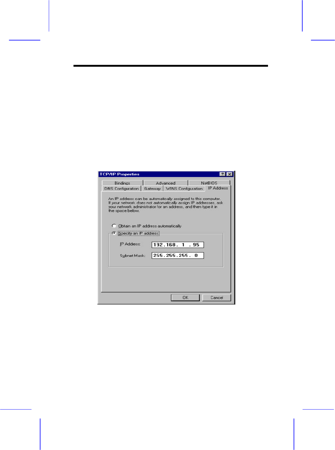
•
Assign (or specify) an IP address for each computer in the
wireless network group. IP addresses are assigned within the
Network properties Configuration tab
– TCP/IP Properties – IP Address settings (i.e. ‘Specify an
IP address’ should be selected).
For example, use a range between 192.168.1.001 to
192.168.1.200 with a subnet mask of 255.255.255.0.
Note: If you are using a DHCP service with a Wireless Bridge
you should not use assigned IP’s.
Wireless Access Point
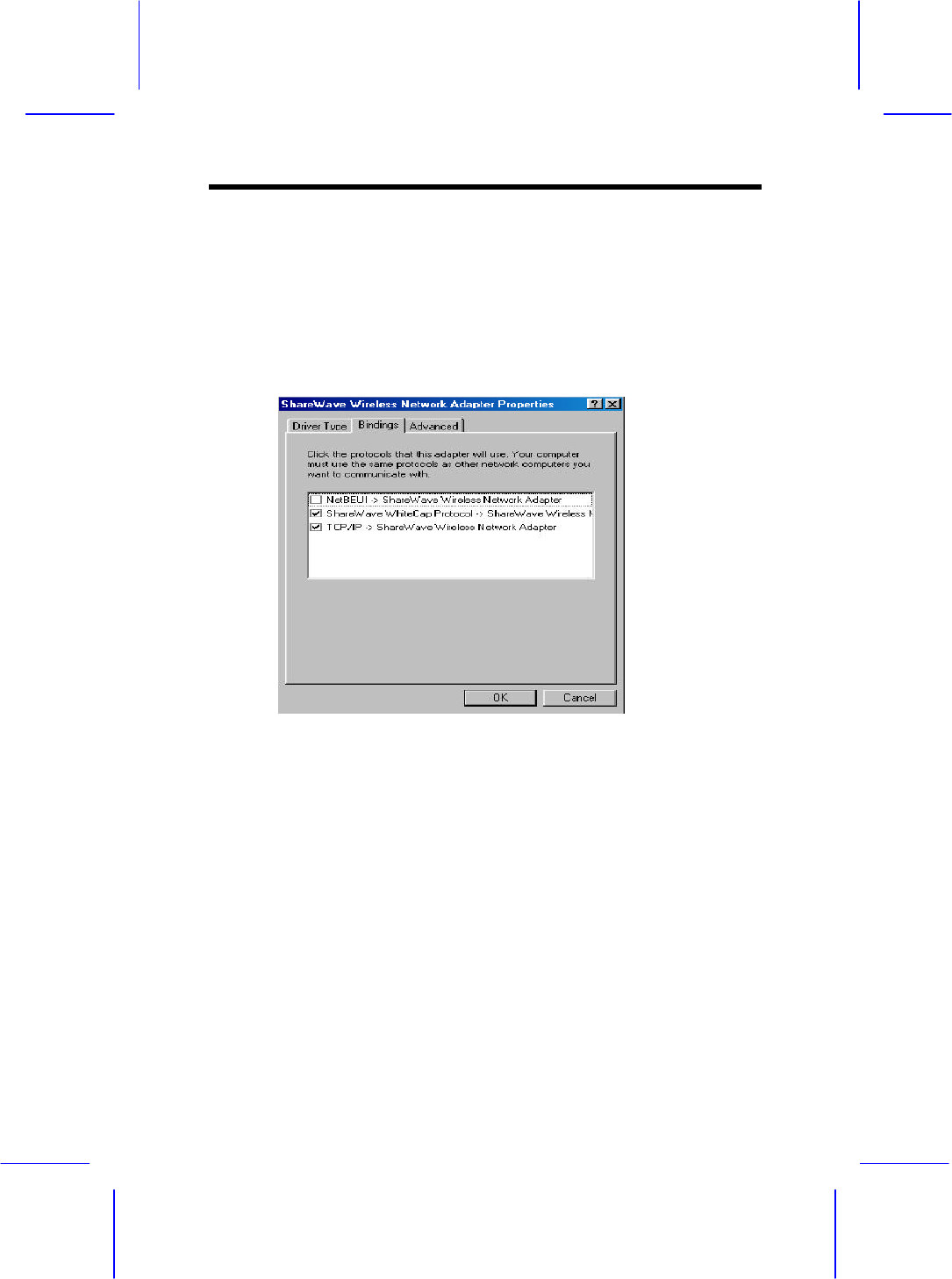
∋ Next, to assure that the ‘fast read’ feature is automatically
used when using TCP/IP protocols verify that the only
protocols selected for the network adapter are TCP/IP and
WhiteCap protocols. To verify which
protocols are selected confirm which check-boxes are selected
within the “Bindings” tab located in the Network adapter
properties (Located in the Network Configuration properties)
* For example, if NetBEUI is selected un-check the box
and click OK
∋ Re-start the system to activate the current changes.
Note: If the system does not shut down (or restart) within 2
minutes manually power down the computer and then power
it back up again.
Trouble playing MPEG streams…
If you encounter problems playing MPEGs from one node to
another, remember the stream or file may be too large/fast for

Wireless Access Point
your CPU to use a software-decode player utility. Try using
hardware MPEG decoder,
often called a DVD decoder card.
Another tip, if your decoder software is hanging or locking up
the system, try different decoding software or switch to a
hardware-based decoding card. Since this product is on the
leading edge of technology, most
software MPEG decoders are not “network aware”. If the stream
is interrupted, even for a moment, the utility may become
unstable or can go into an unrecoverable state.
Wireless Access Point
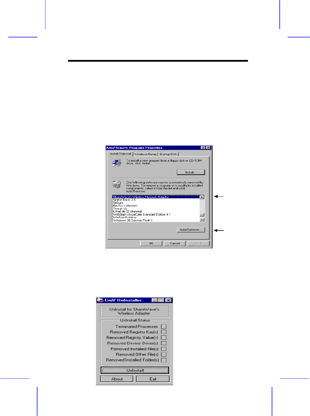
5.1 Windows 98 , Me, and Windows 2000
∋ To completely Un-install the Wireless Network adapter from
your Windows operating system use the Windows
Add/Remove Programs Properties feature located in the
Start /Settings/Control Panel menu.
∋ Select the Wireless Network Adapter and click on the
‘Add/Remove…’ button.
NOTE: The uninstall program UnInstall.exe can also be
invoked by using the Windows Start/Run option and then using
the Browse feature to point to the utility on CD ROM.
∋ Next click the ‘UnInstall’ button.
Wireless Access Point
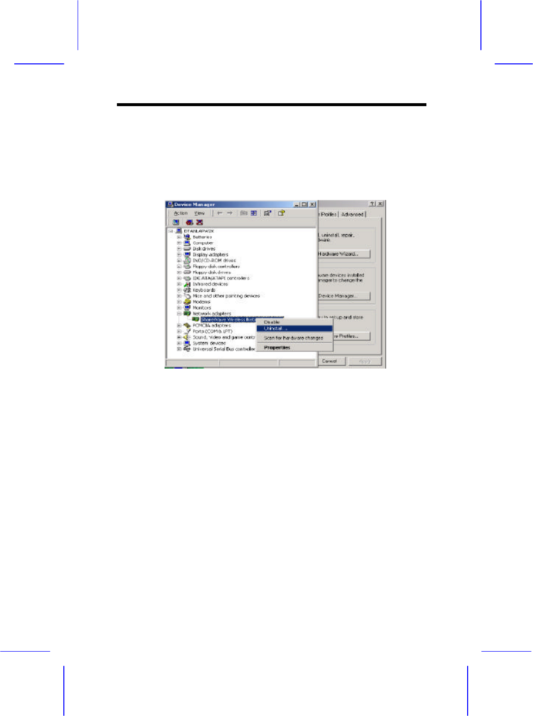
• Click ‘Exit’
• Now use the Windows Device Manager to uninstall the
wireless adapter as illustrated below.
This completes the removal of the adapter. If you wish to
re-install the card reboot your system. If you wish to completely
remove the adapter shut down your computer and remove the
hardware.