Primex Wireless SNSH Synchronous Network System AC Temperature & Humidity Sensor User Manual
Primex Wireless, Inc. Synchronous Network System AC Temperature & Humidity Sensor Users Manual
UserManual.wiki
>
Primex Wireless
>
SNSH User Manual
Users Manual
Navigation menu
Upload a User Manual
Namespaces
Wiki Guide
HTML
PDF
Info
Views
User Manual
Discussion / Help
Navigation
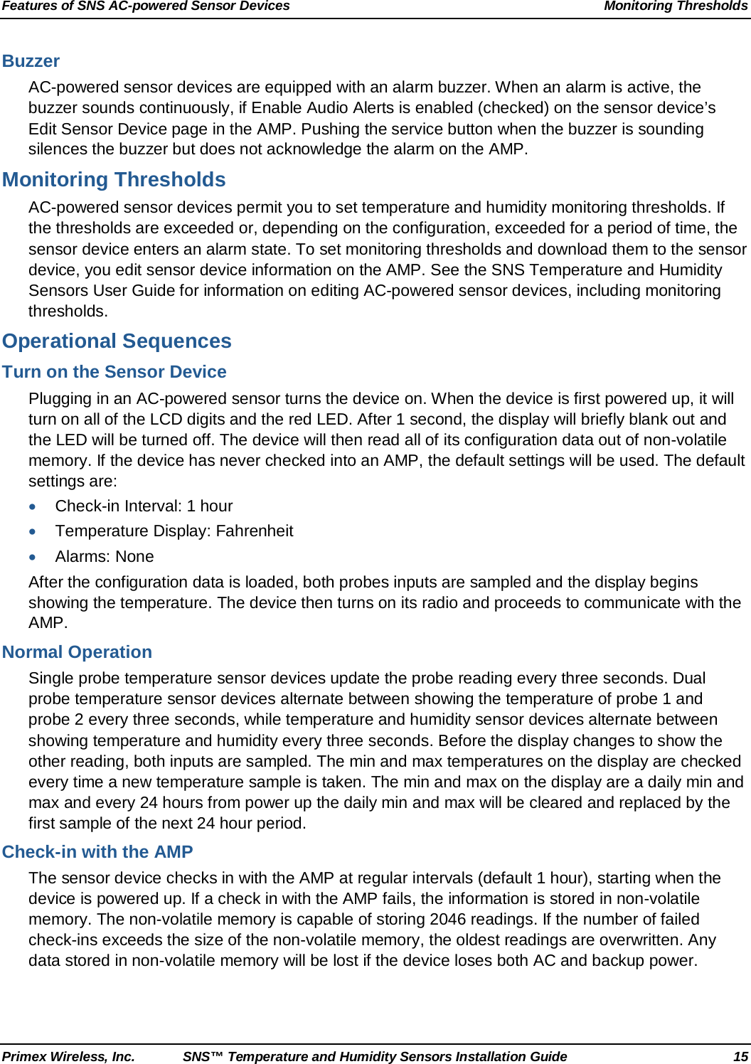
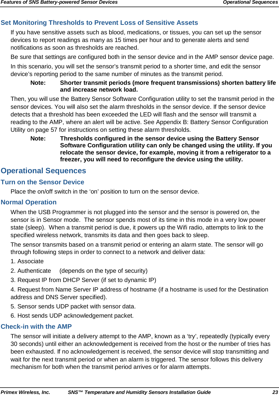
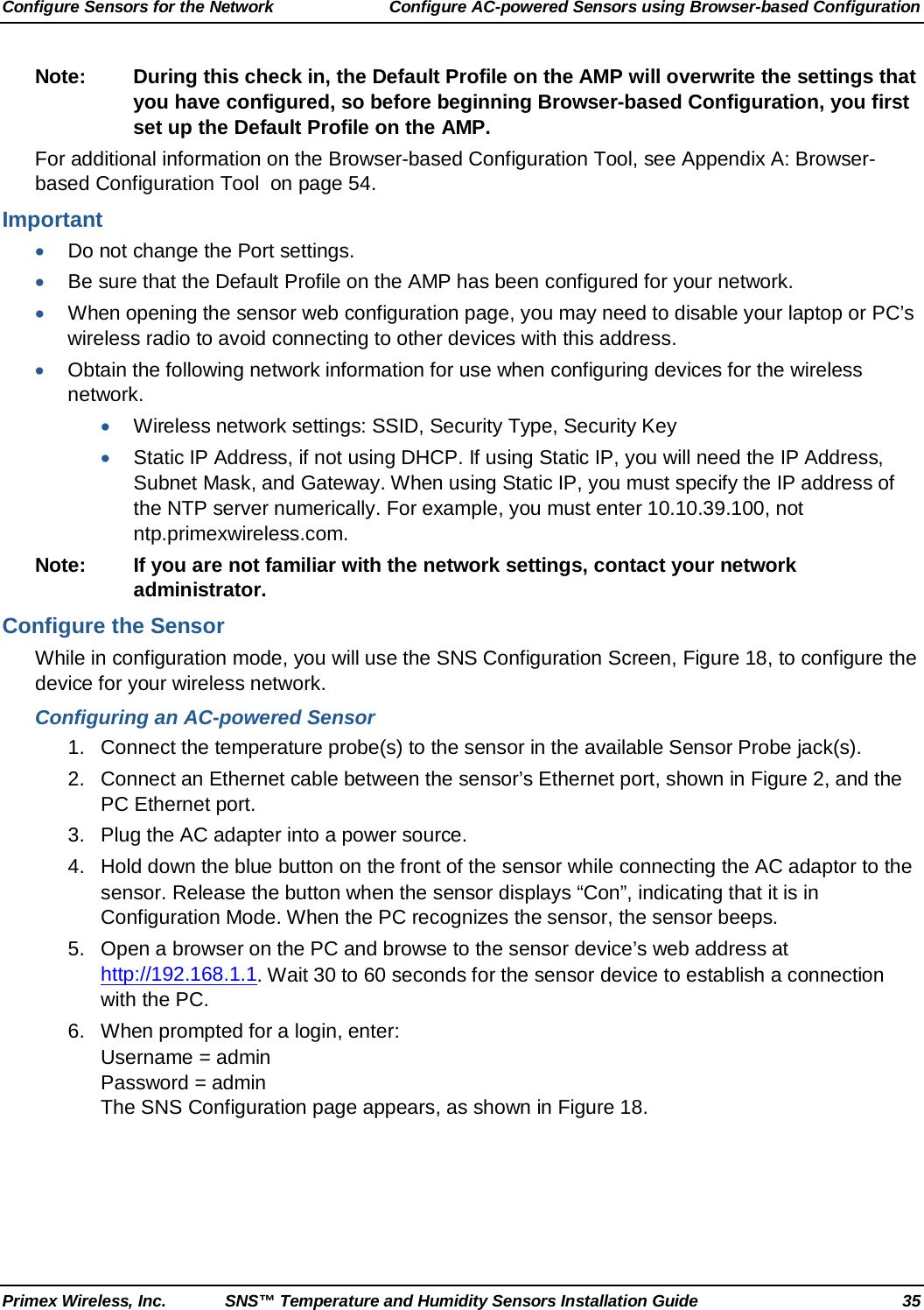

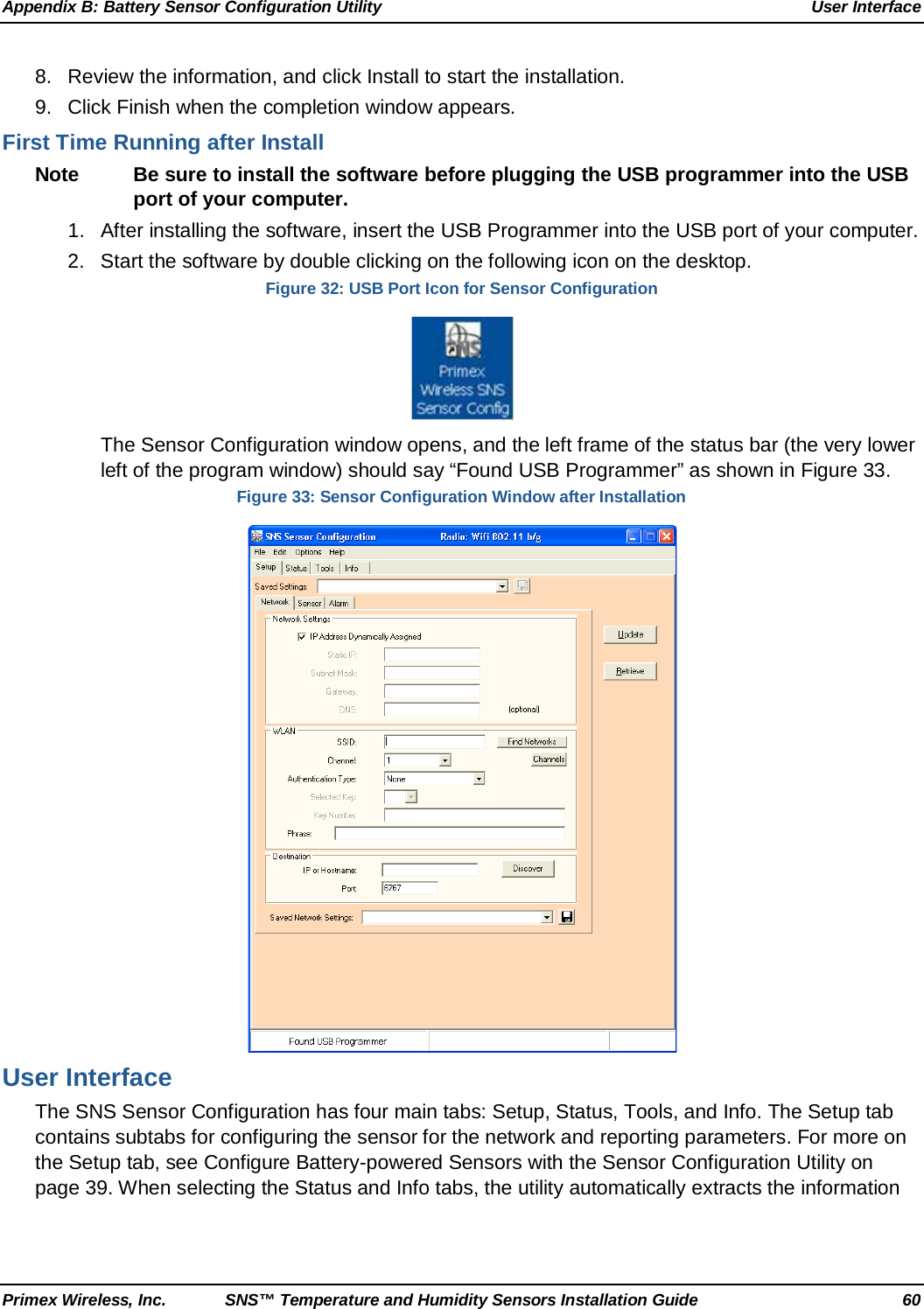
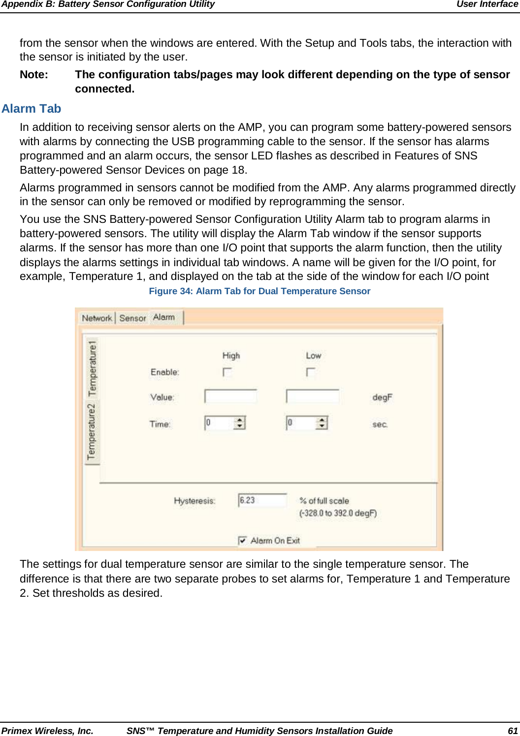
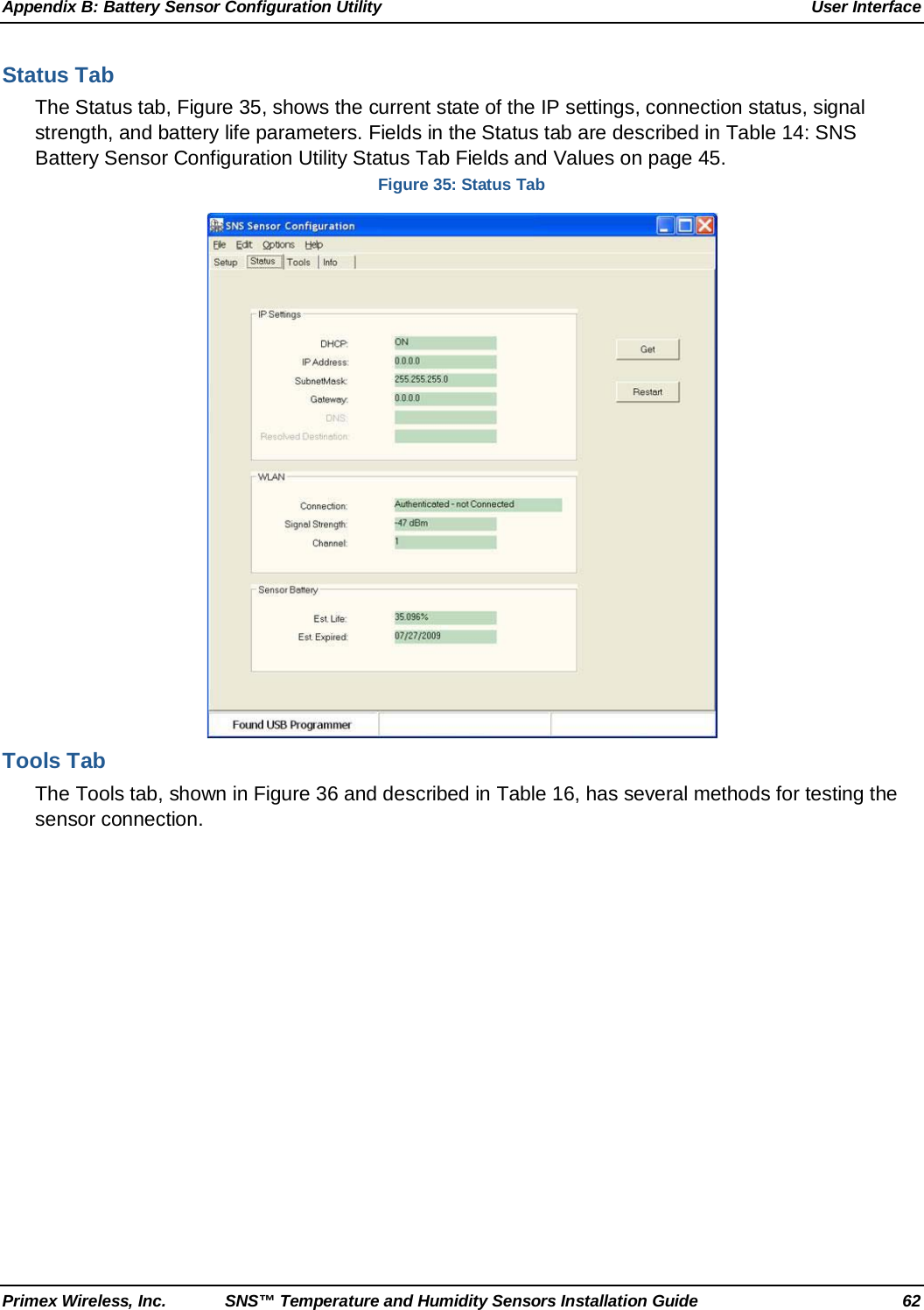

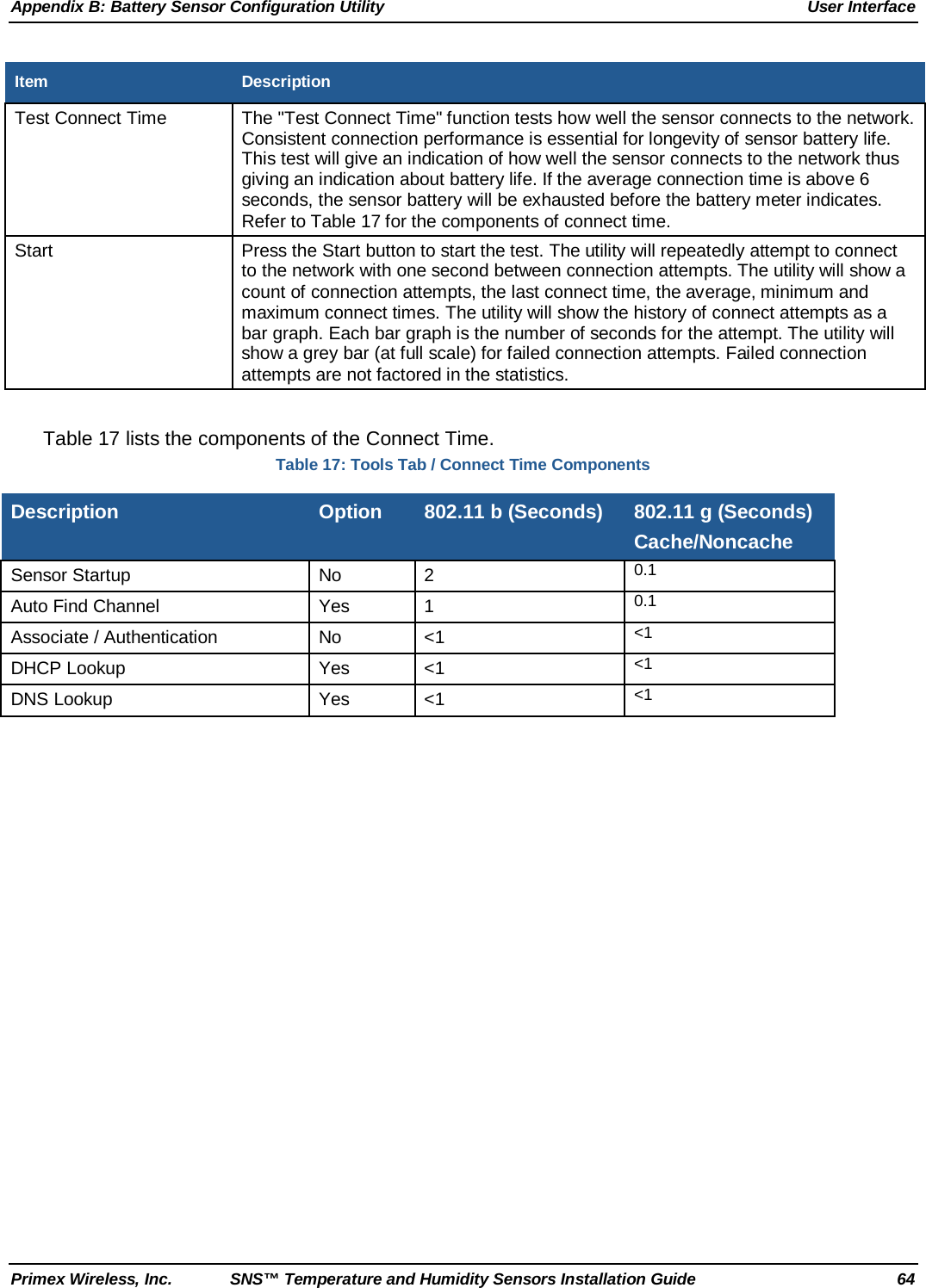
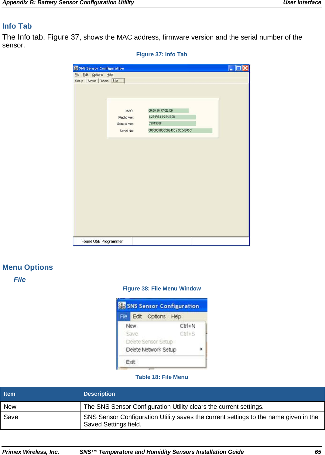
![Appendix B: Battery Sensor Configuration Utility User Interface Primex Wireless, Inc. SNS™ Temperature and Humidity Sensors Installation Guide 70 SNS_Sensor_Cfg.INI The SNS Sensor Configuration Utility stores all its program information in an INI text file called SNS_Sensor_Cfg.INI. Use a text editor to edit this file. Also restart the SNS Sensor Configuration Utility if you make changes to the INI file. The following is description of the user changeable parameters. Override Maximum Number of Tries MaxNumTries=5. Sets the maximum number of tries in the Sensor Tries field. (default max is 5) Auto Find Channels [Settings] ChannelMask=1,2,3,4,5,6,7,8,9,10,11 The ChannelMask parameter under the “Settings” section defines the default channels that are used when a Setup gets created. Edit this parameter to specify the channels for the sensor to search for. [template] ChannelMask=1,2,3,4,5,6,7,8,9,10,11 The utility will use the ChannelMask parameter value in the “Settings” channel to create the value in the template section. If you want to override the definition for a particular setup, then edit this field. Note: Do not set the Channel Auto Find search channels to more than 3 channels. This will have an effect on sensor range and battery life.](https://usermanual.wiki/Primex-Wireless/SNSH/User-Guide-1579332-Page-70.png)