Primex Wireless SNSH Synchronous Network System AC Temperature & Humidity Sensor User Manual
Primex Wireless, Inc. Synchronous Network System AC Temperature & Humidity Sensor Users Manual
Users Manual

SNS™ Temperature and Humidity Sensors
Installation Guide
Document Part No.: SNSDOC-012
10/17/2011

Primex Wireless, Inc. SNS™ Temperature and Humidity Sensors Installation Guide 2
SNS™ Temperature and Humidity Sensors Installation Guide
Product Models
US: SNS2TPS-2, SNS2TPD-2, SNS2TNS-2, SNS2THS-2, SNSATPS, SNSATPD, SNSATHX
UK: SNS2TPS-2, SNS2TPD-2, SNS2TNS-2, SNS2THS-2, SNSGTPS, SNSGTPD, SNSGTHX
EU: SNS2TPS-2, SNS2TPD-2, SNS2TNS-2, SNS2THS-2, SNSCTPS, SNSCTPD, SNSCTHX
Legal Notice
Copyright ©2011 Primex Wireless, Inc. All rights reserved.
SNS is a trademark of Primex Wireless, Inc.
U.S. Patents 6,873,573; 7,352,657. Other Patents Pending.
Printed in the USA.
Reference Documentation
Note: Reference documentation is located on the SNS Resource CD (Q13140) and in the
Support area of the SNS AMP software.
SNS™ Temperature and Humidity Sensors User Guide (SNSDOC-006)
SNS™ AMP Installation and Administration Guide (SNSDOC-005)
Contact Primex Wireless
Web: http://www.primexwireless.com/
E-mail: support@primexwireless.com
United States
Canada
United Kingdom
Telephone
(800) 404-8112
(800) 404-8112
0800-3896996
Hours
7:00am - 5:00pm Central
7:00am - 5:00pm Central
8:30am – 5:00pm GMT
Fax
(262) 248-0061
(905) 952-0134
01422-349462

Primex Wireless, Inc. SNS™ Temperature and Humidity Sensors Installation Guide 3
Contents
Safety Precautions .............................................................................................................................. 5
Safety Precautions ............................................................................................................................. 5
Equipment Precautions ...................................................................................................................... 5
About this Guide .................................................................................................................................. 6
Documentation Overview ................................................................................................................... 6
Guide Conventions ............................................................................................................................. 6
Introducing SNS™ Temperature and Humidity Sensors................................................................... 7
Sensor Devices and Accessories ....................................................................................................... 7
Overview of SNS Sensor Network Installation .................................................................................... 9
Network Requirements for SNS Sensor Devices ............................................................................. 11
Wireless Signal ................................................................................................................................ 11
Wireless Security.............................................................................................................................. 11
Network Protocol and Ports .............................................................................................................. 11
Features of SNS AC-powered Sensor Devices ................................................................................ 12
Network, Power, and Probe Connections ......................................................................................... 12
Service Button .................................................................................................................................. 12
Visual and Auditory Interfaces .......................................................................................................... 13
Monitoring Thresholds ...................................................................................................................... 15
Operational Sequences .................................................................................................................... 15
Features of SNS Battery-powered Sensor Devices ......................................................................... 18
On/Off Switch ................................................................................................................................... 18
Batteries ........................................................................................................................................... 19
Programming Cable Connection ....................................................................................................... 19
Probe Connections ........................................................................................................................... 20
Service Button .................................................................................................................................. 20
Visual and Auditory Interfaces .......................................................................................................... 21
Monitoring Thresholds ...................................................................................................................... 22
Operational Sequences .................................................................................................................... 23
Configure Sensors for the Network .................................................................................................. 25
Select the Configuration Method ...................................................................................................... 25
Edit Default Sensor Profiles .............................................................................................................. 25
Configure AC-powered Sensors using Discovery and Auto-Configuration ........................................ 31
Set up the Network Connection ........................................................................................................ 32
Configure AC-powered Sensors using Browser-based Configuration ............................................... 34
Configure Battery-powered Sensors with the Sensor Configuration Utility ........................................ 39
Install SNS Sensor Devices and Accessories .................................................................................. 47
Install SNS Temperature and Humidity Sensors ............................................................................... 47
Install a Thermobuffer ...................................................................................................................... 47
Maintain Sensor Devices ................................................................................................................... 49
Replace Batteries in Battery-powered Sensor Devices ..................................................................... 49

Contents
Primex Wireless, Inc. SNS™ Temperature and Humidity Sensors Installation Guide 4
Troubleshoot Sensors ....................................................................................................................... 50
Troubleshooting AC-powered Sensors ............................................................................................. 50
Troubleshooting Battery-powered Sensors ....................................................................................... 50
Appendix A: Browser-based Configuration Tool............................................................................. 54
Action Buttons .................................................................................................................................. 54
Appendix B: Battery Sensor Configuration Utility........................................................................... 57
Installing the Configuration Utility ..................................................................................................... 57
User Interface ................................................................................................................................... 60
Appendix C: Regulatory Compliance ............................................................................................... 71
FCC Compliance .............................................................................................................................. 71

Primex Wireless, Inc. SNS™ Temperature and Humidity Sensors Installation Guide 5
Safety Precautions
Read this document thoroughly before performing any installation or service procedures.
Safety Precautions
SNS sensors are designed for indoor use only and are not weather protected. Operating the
sensors outdoors, or in wet areas is an electrical hazard and may damage the temperature sensor
while nullifying the warranty.
Equipment Precautions
• To avoid possible electric shock or damage to an SNS sensor, make sure that it is not powered
when mounting it.
• For healthcare facilities, sensors are not intended for patient use and must not be installed
within 6ft (2m) of patient contact.
• SNS sensors may be cleaned with a cloth moistened with water or a common disinfectant.
Be sure to test any cleaning solutions on a small area of the
sensor before using it on the entire sensor.

Primex Wireless, Inc. SNS™ Temperature and Humidity Sensors Installation Guide 6
About this Guide
Documentation Overview
Depending on your function(s), you will find the following documents most helpful:
I am… I want to… Document I need…
Installing the SNS AMP
Server and Software • Install the AMP
• Put the AMP on the network
• Set time on the AMP
• Add AMP Users and Assign
Roles
• Configure Network and Time
Settings
• Install Sensor Licenses
• Manage Background Jobs
SNS AMP Quick Start Guide
SNS AMP Installation and
Administration Guide
Adding Sensors to the
Network • Create Default Profiles
• Configure Sensors
SNS Temperature and Humidity
Sensors Installation Guide
Installing Sensors • Mount Sensors
• Use a Thermobuffer
SNS Temperature and Humidity
Sensors Installation Guide
Using Sensors • Modify Temperature and
Humidity Thresholds
• Handle Alarms
SNS Temperature and Humidity
Sensors User Guide
Managing, Monitoring, and
Reporting on Sensors • Manage Sensors
• Monitor Sensors
• View and Print Sensor
Reports
SNS Temperature and Humidity
Sensors User Guide
Maintain Sensors • Upgrade Sensor Firmware
• Change Batteries
SNS Temperature and Humidity
Sensors User Guide
Guide Conventions
This guide uses typographical conventions to highlight specific types of information.
Information Example
Graphical user interface tab and menu sequence. Choose Sensors > Auto-Config.
Graphical user interface pages and controls. Return to the Sensor Devices page. Click Save.
Command line input. Type the following:
>
cd /var/sns/sns-install
User-specified input. Open a browser to http:your.amp.address.com.
Primex Wireless, Inc. SNS™ Temperature and Humidity Sensors Installation Guide 7
Introducing SNS™ Temperature and Humidity Sensors
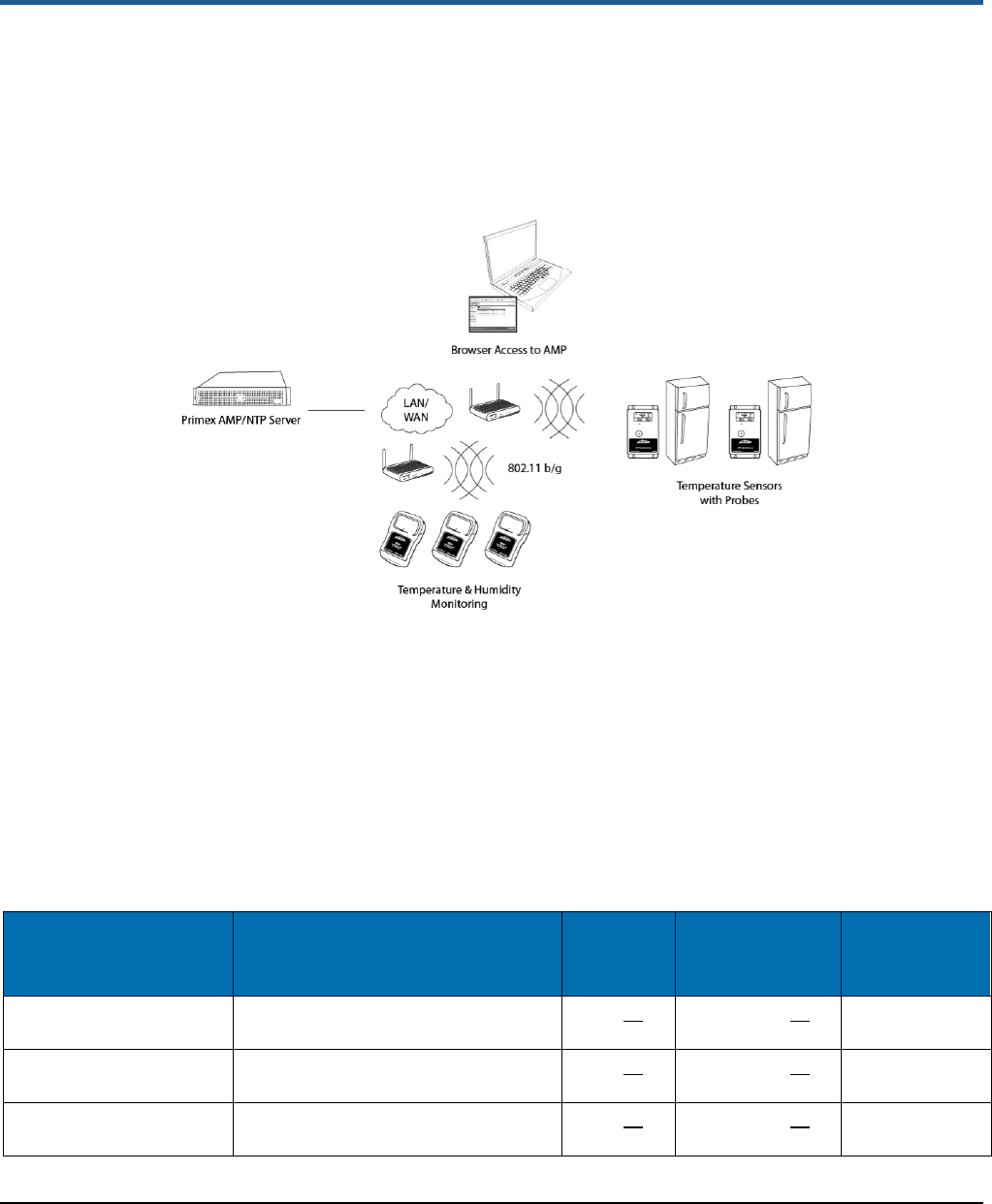
SNS™ Temperature and Humidity Sensors provide monitoring and logging of environmental
conditions throughout your facilities. SNS Temperature and Humidity Sensors (sensor devices)
communicate with the Synchronized Network Solutions (SNS) Application Management Platform
(AMP)/Network Time Protocol (NTP) server over wireless 802.11 b/g networks. (Some sensor
devices can also communicate over the wired Ethernet network.) Figure 1 shows the architecture of
an SNS Temperature and Humidity Sensors network.
Figure 1: SNS Temperature and Humidity Sensors Network
Sensor Devices and Accessories
Primex Wireless offers battery- and AC-powered sensor devices and probes. An important
accessory for both AC- and battery powered external probe sensors is the SNS thermobuffer, which
enables sensor readings to be based on the temperature of the refrigerated assets rather than on
the air temperature.
AC-powered Sensor Devices and Accessories
Table 1 and Table 2 describe the AC-powered sensor devices and accessories. For more on AC-
powered sensor devices, see Features of SNS AC-powered Sensor Devices on page 12.
Table 1: AC-powered Sensor Device Specifications
Sensor Device Part
Number Sensor Device Description Input
Power Current Draw Sensor Device
Operating
Range
SNSATPD Dual probe temperature sensor 6-12V--- 300mA@9V--- 32°F to 95°F
(0°C to 35°C)
SNSATPS Single probe temperature sensor 6-12V--- 300mA@9V--- 32°F to 95°F
(0°C to 35°C)
SNSATHX Temperature and humidty sensor 6-12V--- 300mA@9V--- 32°F to 95°F
(0°C to 35°C)

Introducing SNS™ Temperature and Humidity Sensors Sensor Devices and Accessories
Primex Wireless, Inc. SNS™ Temperature and Humidity Sensors Installation Guide 8
Table 2: AC-powered Single and Dual Probe Sensor Device Accessories
Accessory Part
Number Accessory Description Probe Operating Range
SNS6C1 Thermistor, AC temperature sensor (⅛”
probe) -22°F to 194°F (-30°C to 90°C)
SNS6C2 Thermistor, NIST Traceable AC
temperature sensor (¼” probe), -22°F to 194°F (-30°C to 90°C)
Q13563-1 25’ Thermistor Extension Cable Minor loss in accuracy in above when
extension cables are used
Q13563-2 50’ Thermistor Extension Cable Minor loss in accuracy in above when
extension cables are used
Battery-powered Sensor Device Specifications
Table 3 and Table 4 describe the battery-powered sensor devices and accessories.
Table 3: Battery-powered Sensor Device Specifications
Sensor Device Part
Number Sensor Device Description Input
Power Sensor Device Operating Range
SNS2TPS-2 Single probe, dual battery
temperature sensor 2 AA
batteries -40°C-85°C
SNS2TPD-2 Dual probe, dual battery
temperature sensor 2 AA
batteries -40°C-85°C
SNS2TNS-2 Sealed, dual battery temperature
sensor 2 AA
batteries -40°C-60°C
SNS2THS-2 Dual battery temperature and
humidity sensor 2 AA
batteries -40°C-60°C
Table 4: Battery-powered Sensor Device Accessories
Accessory Part
Number Accessory Description Probe Operating Range
SNS6AC4 Standard 4” RTD Probe, 6’ Teflon Cable -50°C to 125°C
SNS2AC4 Standard 4” RTD Probe, 2’ Teflon Cable -50°C to 125°C
SNS6BC4 Cryo 4” RTD Probe, 6’ Sheathed Teflon
Cable -200°C to 125°C
SNS2BC4 Cryo 4” RTD Probe, 2’ Sheathed Teflon
Cable -200°C to 125°C
Q13332 USB Programming Cable N/A
SNS888 AA Lithium Battery 1.5v N/A

Introducing SNS™ Temperature and Humidity Sensors Overview of SNS Sensor Network Installation
Primex Wireless, Inc. SNS™ Temperature and Humidity Sensors Installation Guide 9
SNS Thermobuffers
A thermobuffer can be used with battery- and AC-powered single and dual probe temperature
sensors to simulate the actual temperature of contents within coolers or freezers. The thermobuffer
is a bottle of food-grade glycol into which the temperature probe is placed inside the refrigerator.
The thermobuffer simulates refrigerated items, which change temperature more slowly than the air
when the refrigerator door is opened. Using a thermobuffer with sensor devices limits the impact of
fluctuating air temperature on sensor readings and helps provide a higher degree of measurement
accuracy. The thermobuffer is effective to a minimum temperature of -27° F.
Table 5: SNS Thermobuffer Accessories
Accessory Part Number Accessory Description
SNSGRP SNS Thermobuffer, 4 oz. Glycol Bottle for RTD Probe and Thermistor (NIST)
SNSGLY-1 1 Gallon Food Grade Glycol
Overview of SNS Sensor Network Installation
Prerequisites to SNS Sensor Installation
The following tasks must be complete before installing SNS Sensors.
• Install and set up the SNS Application Management Platform (AMP)/Network Time Protocol
(NTP) server.
• Enter the SNS Sensors license key in the AMP.
• Assign the Sensor Admin role to the AMP administrator or other user login.
This installation guide assumes that the AMP and Sensors license are installed and that you can
log in to the AMP as a user with the Sensor Admin role. See the SNS AMP Installation and
Administration Guide and the SNS Temperature and Humidity Sensors User Guide for details.
Plan the Installation
Sensor device installation begins by planning where to place sensor devices and ensuring that the
wireless or wired network is available at these locations.
Note: Sensor devices must have adequate signal to support wireless operation. Sensor
devices will work in areas where a wireless laptop can connect to the network or
where signal to noise level measures 20 dB or greater. If wireless signal is
inadequate, a wireless Access Point may be added in proximity to improve local
signal strength. AC-powered sensor devices can also be connected to the
Ethernet network via the RJ45 connector.
Configure Sensor Devices for the Network
Sensor devices arrive at your facility with no knowledge of the network. The next step in installing
the SNS Sensors network is to configure sensor devices. See Configure Sensors for the Network
on page 25 for details.
Install and Verify Sensor Devices
Once sensors are configured and you know they can connect to the network, they are ready for
installation in their permanent locations. See Install SNS Sensor Devices and Accessories on page
47 for details.

Introducing SNS™ Temperature and Humidity Sensors Overview of SNS Sensor Network Installation
Primex Wireless, Inc. SNS™ Temperature and Humidity Sensors Installation Guide 10
View and Update Sensor Device Information in the AMP
During sensor device configuration and upon installation, you will use AMP screens to verify that
the sensor device is communicating with the AMP. You will also use AMP pages to enter
information, such as the location of the sensor device or alerting thresholds. See the SNS
Temperature and Humidity Sensors User Guide for details.

Primex Wireless, Inc. SNS™ Temperature and Humidity Sensors Installation Guide 11
Network Requirements for SNS Sensor Devices
SNS Temperature and Humidity Sensors work on 802.11 b/g wireless networks. Some sensors also
work on wired Ethernet networks. This section describes the requirements for the SNS
Temperature and Humidity Sensors network.
Wireless Signal
Sensor devices must have adequate signal to support wireless operation. Sensor devices will work
in areas where a wireless laptop can connect to the network or where signal to noise level
measures 20 dB or greater. If wireless signal is inadequate, a wireless Access Point may be added
in proximity to improve local signal strength. AC-powered sensor devices can also be connected to
the Ethernet network via the RJ45 connector.
Wireless Security
AC-powered Sensor Devices
AC-powered sensor devices support WEP, WPA, and WPA2 encryption standards with LEAP,
EAP-FAST, and PEAP authentication.
Battery-powered Sensor Devices
Battery-powered sensor devices support WEP - 128, WPA-TKIP, and WPA2-AES encryption
standards.
Network Protocol and Ports
AC-powered Sensor Devices
AC-powered sensors send sensor device data via UDP packets. Ports 1600 and 1640 must be
open on the network for data transmission and configuration.
Battery-powered Sensor Devices
Battery-powered sensors send sensor device data via UDP packets. Port 6767 must be open on
the network. Packets are small (less than 75 bytes).
Primex Wireless, Inc. SNS™ Temperature and Humidity Sensors Installation Guide 12
Features of SNS AC-powered Sensor Devices
This section contains the following topics:
• Network, Power, and Probe Connections
• Service Button
• Visual and Auditory Interfaces
• Monitoring Thresholds
• Operational Sequences
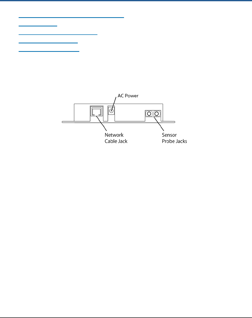
Network, Power, and Probe Connections
Network, power, and probe connections are located on the side of AC-powered sensors, as shown
in Figure 2. Dual-probe sensor devices contain two probe jacks.
Figure 2: Network, Power, and Probe Connections on AC-Powered Temperature Sensor (SNSATPD)
Network Connection
The RJ-45 network connection allows you to connect a standard Ethernet cable to the sensor
device. The network connection is used during browser-based configuration and if the sensor
device is configured to operate on the wired Ethernet network. For details on configuration, see
Configure Sensors for the Network on page 25.
AC-Power Connection
AC-powered sensor devices come with a power supply. Plugging in the power supply and
connecting it to the sensor device turns on the sensor device. AC-powered sensor devices must be
connected to AC power for normal operation.
Probe Connection(s)
AC-powered temperature sensor devices have one or two probe connections depending on the
sensor device model.
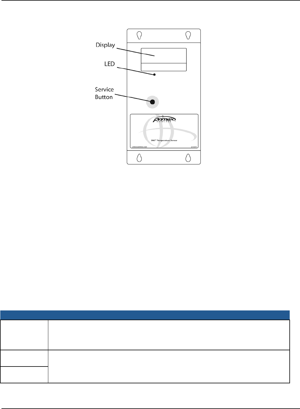
Service Button
The service button is located on the front of AC-powered sensor devices, as shown in Figure 3.
Features of SNS AC-powered Sensor Devices Visual and Auditory Interfaces
Primex Wireless, Inc. SNS™ Temperature and Humidity Sensors Installation Guide 13
Figure 3: Service Button, Display, and LED on AC-Powered Temperature Sensor (SNSATPD)
The service button has several uses depending on the status of the sensor device.
• To enable browser-based configuration, pressing and holding the service button while plugging
in the sensor device causes the device to enter configuration mode.
• During normal operation and discovery and auto-configuration, pushing the service button
causes the sensor device to sound the beeper and check in with the AMP.
• During an alarm, pushing the service button cancels the alarm and stops the LED from flashing
but does not acknowledge the alarm on the AMP. Pushing the service button during an alarm
also does not sound the beeper or cause the sensor device to check in with the AMP.
Visual and Auditory Interfaces
The display and LED, shown in Figure 3, are visual indicators of sensor device status and sensor
readings. The sensor device also communicates its status using beeps.
Display
Table 6 describes the display functions for AC-powered sensor devices.
Table 6: AC-powered Sensor Device Display
Item Description
38.1° F
65%RH Current reading of probe. For dual probe sensors, the reading alternates between
showing the reading of probe 1 and probe 2 every three seconds. Numbers ‘1’ and ‘2’ in
the upper left corner of the display indicate which reading is displayed. Before the display
changes to show the other probe’s temperature, both probe inputs are sampled.
MIN °F
32.0 Latest min and max temperature values. The min and max temperatures on the display
are checked every time a new sample is taken. The min and max on the display are a
daily min and max and every 24 hours from power up the daily min and max will be
cleared and replaced by the first sample of the next 24 hour period.
MAX °F
40.0

Features of SNS AC-powered Sensor Devices Visual and Auditory Interfaces
Primex Wireless, Inc. SNS™ Temperature and Humidity Sensors Installation Guide 14
Item Description
MIN %RH
75.0 Latest min and max relative humidity values. The min and max relative humidity on the
display are checked every time a new sample is taken. The min and max on the display
are a daily min and max and every 24 hours from power up the daily min and max will be
cleared and replaced by the first sample of the next 24 hour period.
Temperature and Humidity sensors only.
MAX %RH
60.0
dIS One of the probes is disconnected from the device. If the probe was never plugged in
since power up, no min or max will be shown until a probe is connected, though the
device will continue to check in with the AMP at its normal interval.
Temperature sensors only.
LO Temperature below -40 °C. No temperature sample is taken or stored, though the device
will continue to check in with the AMP at its normal interval. If the temperature drops much
further below -40 °C the display will change from LO to SHr.
Temperature sensors only.
HI Temperature above 90 °C.
Temperature sensors only.
SHr One of the probe inputs is shorted. No temperature sample is taken or stored, though the
device will continue to check in with the AMP at its normal interval. If the probe input was
short since power up, no min or max will be displayed until the short is removed.
Temperature sensors only.
CON Device is in configuration mode.
LO AC
(Appears
instead of
MIN/MAX or
%RH)
Device is running on backup power. When running on backup power, the device slows its
display rate and probe sampling rate down from every three seconds to every 15 seconds
to conserve power. To save power, the radio, LED, and buzzer are never turned on in this
mode.
LED
The LED has several meanings depending on the status of the sensor device.
• When an alarm is active, the LED on AC-powered sensors flashes once per second. Pushing
the service button when the LED is flashing stops the flashing but does not acknowledge the
alarm on the AMP.
• When in Find mode, the LED flashes rapidly 3 times per second. For information on Find mode,
see the SNS Temperature and Humidity Sensors User Guide.
• When powered up, the LED illuminates briefly.
Beeps
When the service button is pushed during normal operation, the sensor device emits two beeps and
activates the radio to contact the AMP. Once a successful exchange with the AMP occurs, the
device sounds the following series of beeps:
• 1 beep indicates that the radio booted.
• 2 beeps indicate that the sensor device has connected to network.
• 3 beeps indicate that the sensor device has connected to the AMP. Connecting to the
AMP usually takes about 25 seconds assuming a standard wireless connection with
WPA2 security.

Features of SNS AC-powered Sensor Devices Monitoring Thresholds
Primex Wireless, Inc. SNS™ Temperature and Humidity Sensors Installation Guide 15
Buzzer
AC-powered sensor devices are equipped with an alarm buzzer. When an alarm is active, the
buzzer sounds continuously, if Enable Audio Alerts is enabled (checked) on the sensor device’s
Edit Sensor Device page in the AMP. Pushing the service button when the buzzer is sounding
silences the buzzer but does not acknowledge the alarm on the AMP.
Monitoring Thresholds
AC-powered sensor devices permit you to set temperature and humidity monitoring thresholds. If
the thresholds are exceeded or, depending on the configuration, exceeded for a period of time, the
sensor device enters an alarm state. To set monitoring thresholds and download them to the sensor
device, you edit sensor device information on the AMP. See the SNS Temperature and Humidity
Sensors User Guide for information on editing AC-powered sensor devices, including monitoring
thresholds.
Operational Sequences
Turn on the Sensor Device
Plugging in an AC-powered sensor turns the device on. When the device is first powered up, it will
turn on all of the LCD digits and the red LED. After 1 second, the display will briefly blank out and
the LED will be turned off. The device will then read all of its configuration data out of non-volatile
memory. If the device has never checked into an AMP, the default settings will be used. The default
settings are:
• Check-in Interval: 1 hour
• Temperature Display: Fahrenheit
• Alarms: None
After the configuration data is loaded, both probes inputs are sampled and the display begins
showing the temperature. The device then turns on its radio and proceeds to communicate with the
AMP.
Normal Operation
Single probe temperature sensor devices update the probe reading every three seconds. Dual
probe temperature sensor devices alternate between showing the temperature of probe 1 and
probe 2 every three seconds, while temperature and humidity sensor devices alternate between
showing temperature and humidity every three seconds. Before the display changes to show the
other reading, both inputs are sampled. The min and max temperatures on the display are checked
every time a new temperature sample is taken. The min and max on the display are a daily min and
max and every 24 hours from power up the daily min and max will be cleared and replaced by the
first sample of the next 24 hour period.
Check-in with the AMP
The sensor device checks in with the AMP at regular intervals (default 1 hour), starting when the
device is powered up. If a check in with the AMP fails, the information is stored in non-volatile
memory. The non-volatile memory is capable of storing 2046 readings. If the number of failed
check-ins exceeds the size of the non-volatile memory, the oldest readings are overwritten. Any
data stored in non-volatile memory will be lost if the device loses both AC and backup power.

Features of SNS AC-powered Sensor Devices Operational Sequences
Primex Wireless, Inc. SNS™ Temperature and Humidity Sensors Installation Guide 16
Pushing the service button during normal operation forces the sensor device to check in with the
AMP. When the service button is pressed, the sensor device will emit a series of beeps. The beeps
signal the following connection sequence: 1= radio booted, 2 = connected to network, 3 =
connected to the AMP (usually takes about 25 seconds to hear the beep assuming a standard
wireless connection with WPA2 security).
Configuration Mode
Holding the button down while plugging the device in causes the device to enter configuration
mode, regardless of whether it has been configured previously. While in configuration mode, you
can perform browser-based configuration. When the device first enters configuration mode, it beeps
once. This beep indicates to the user that they can take their finger off the button. While in
configuration mode, the device flashes CON for one second and then goes blank for the next
second. The sensor device continues to flash CON while in configuration mode. See Configure
Sensors for the Network on page 25 for information on configuration.
Handle Alarms
When an alarm is active, the LED on the front of the sensor device flashes once per second and the
buzzer sounds continuously, if Enable Audio Alerts is enabled (checked) on the sensor device’s
Edit Sensor Device page in the AMP.
If an alarm is active (LED is flashing), pushing the button cancels the alarm and stops the LED from
flashing, but does not acknowledge the alarm on the AMP. Pushing the button during an alarm also
does not sound the beeper or cause the sensor device to check in with the AMP.
The behavior of the sensor device after cancelling an alarm depends on how the device is
configured in the sensor device’s Edit Sensor Device page:
• If a threshold has been exceeded with High Span Minutes blank and Audio Reset Period set at
Indefinite, pushing the button cancels the alarm and an alarm will not occur again until the
sensor goes back in range and then out of range again.
• If a threshold has been exceeded with the Audio Reset Period is configured but High Span
Minutes is blank, the alarm does not sound again until the Audio Reset Period expires.
• If a Span Minutes has been exceeded, pushing the button cancels the alarm. If the device
remains out of range and if an Audio Reset Period is configured, the alarm will not sound again
until the Audio Reset Period expires.
• If a Span Minutes has been exceeded, pushing the button cancels the alarm. If an Audio Reset
Period is not configured, the alarm sounds again once Span Minutes runs out a second time.
Backup Power
AC-powered sensor devices have an internal super cap that allows the devices to continue to do
many of their functions during an AC power outage. It normally takes about 8 hours to fully charge a
super cap. Once fully charged, an AC-powered sensor device should be able to run on backup
power for up to 4 hours.
All data being collected by the probes is stored in non-volatile memory. This data will be lost if
backup power fails. If AC power is restored before backup power fails and the temperature stayed
within the set limits, all of the readings will be sent to the AMP as a single check in with the current
temperature for the entire duration of the power outage. If a high or low limit is crossed while
running on backup power, the data will be saved to non-volatile memory with a timestamp. This

Features of SNS AC-powered Sensor Devices Operational Sequences
Primex Wireless, Inc. SNS™ Temperature and Humidity Sensors Installation Guide 17
data will be erased in the event that backup power fails. If it does not fail, these archived readings
will be sent to the AMP as well as current temperature readings when AC power is restored so that
you may see when temperatures went in and out of limits and for what duration. In the AMP Sensor
Readings page, archived readings appear with a check mark in the Logged Readings column and
have the same Transmit Count as the current reading.
Primex Wireless, Inc. SNS™ Temperature and Humidity Sensors Installation Guide 18
Features of SNS Battery-powered Sensor Devices
This section contains the following topics:
• On/Off Switch
• Batteries
• Programming Cable Connection
• Probe Connections
• Service Button
• Visual and Auditory Interfaces
• Monitoring Thresholds
• Operational Sequences
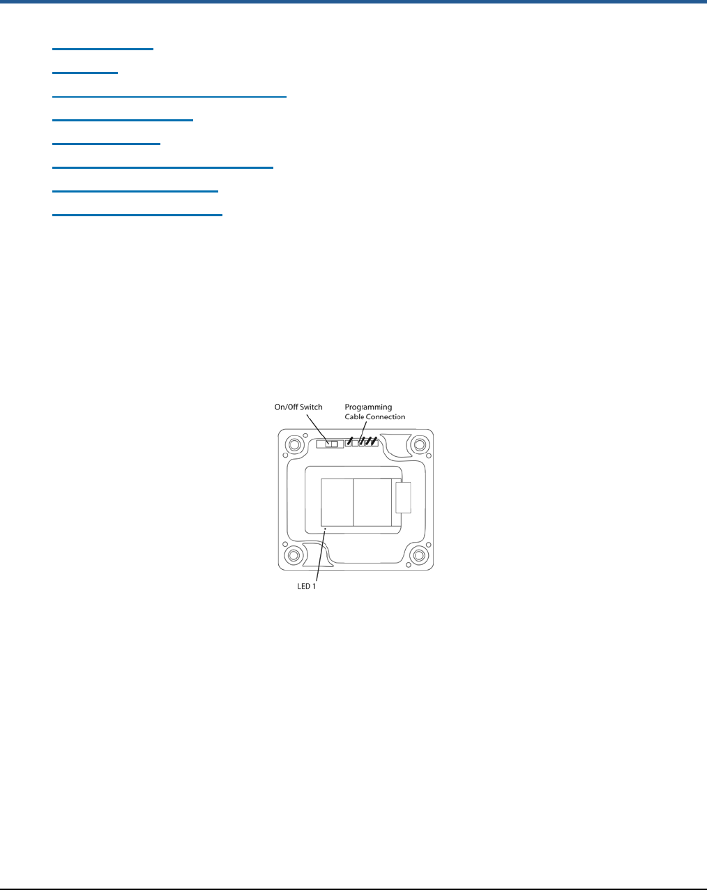
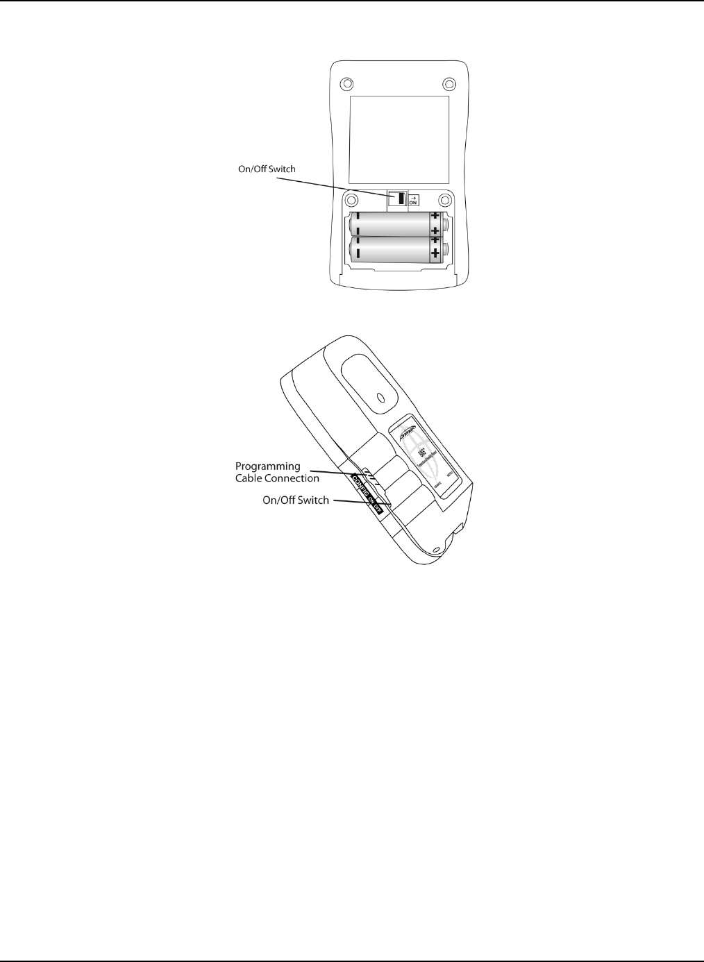
On/Off Switch
Battery-powered sensor devices have on/off switches. The sensor devices must be turned on
during configuration and normal operation. As shown in Figure 4, the on/off switch on model
SNS2TNS-2 is located inside the sensor device. On this model, moving the switch away from the
programming cable connection turns the sensor device on. On model SNS2TPS-2, the on/off switch
is located in the battery compartment, as shown in Figure 5. On model, SNS2THS-2, it is on the
side (Figure 6).
Figure 4: Inside Model SNS2TNS-2
Features of SNS Battery-powered Sensor Devices Batteries
Primex Wireless, Inc. SNS™ Temperature and Humidity Sensors Installation Guide 19
Figure 5: On/Off Switch Model SNS2TPS-2
Figure 6: Side of Model SNS2THS-2
Batteries
SNS battery-powered sensors use two AA batteries located inside the sensor (Model SNS2TNS-2,
Figure 4; Model SNS2TPH-2, Figure 12) or in an externally accessible battery compartment (Model
SNS2TPS-2, Figure 5).
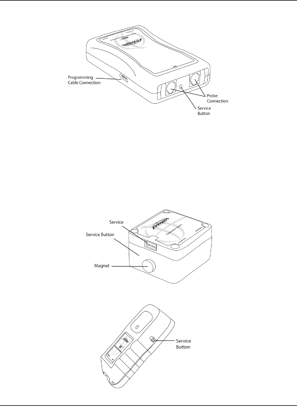
Programming Cable Connection
Battery-powered sensor devices come with a USB programming cable for use when configuring the
sensor device. The standard USB connector connects to the computer that is running the
configuration software utility. The other end of the programming cable connects to the sensor
device’s programming connection. For information on configuring sensors, see Configure Sensors
for the Network on page 25.
As shown in Figure 4, Figure 6, and Figure 7, the location of the programming cable connection
depends on the sensor model.
Features of SNS Battery-powered Sensor Devices Probe Connections
Primex Wireless, Inc. SNS™ Temperature and Humidity Sensors Installation Guide 20
Figure 7: Connections and Service Button on Model SNS2TPS-2
Probe Connections
Single and dual external probe sensor devices contain probe jacks on the end of the sensor device,
as shown in Figure 7.
Service Button
The service button is located on the side or end of the sensor device, depending on the model (See
Figure 7 and Figure 9). As shown in Figure 8, on model SNS2TNS-2, the service button is inside
the sensor device. On this model, the service button is activated by swiping the outside of the
sensor device with the supplied magnet.
Figure 8: Service Button on Model SNS2TNS-2
Figure 9: Service Button on Model SNS2THS-2
Features of SNS Battery-powered Sensor Devices Visual and Auditory Interfaces
Primex Wireless, Inc. SNS™ Temperature and Humidity Sensors Installation Guide 21
The service button has several uses depending on the status of the sensor device.
• Activating the service button causes the sensor device to check in with the AMP.
• During an alarm, activating the service button cancels the alarm and stops the LED from
flashing but does not acknowledge the alarm on the AMP. Activating the service button during
an alarm also does not sound the beeper or cause the sensor device to check in with the AMP.
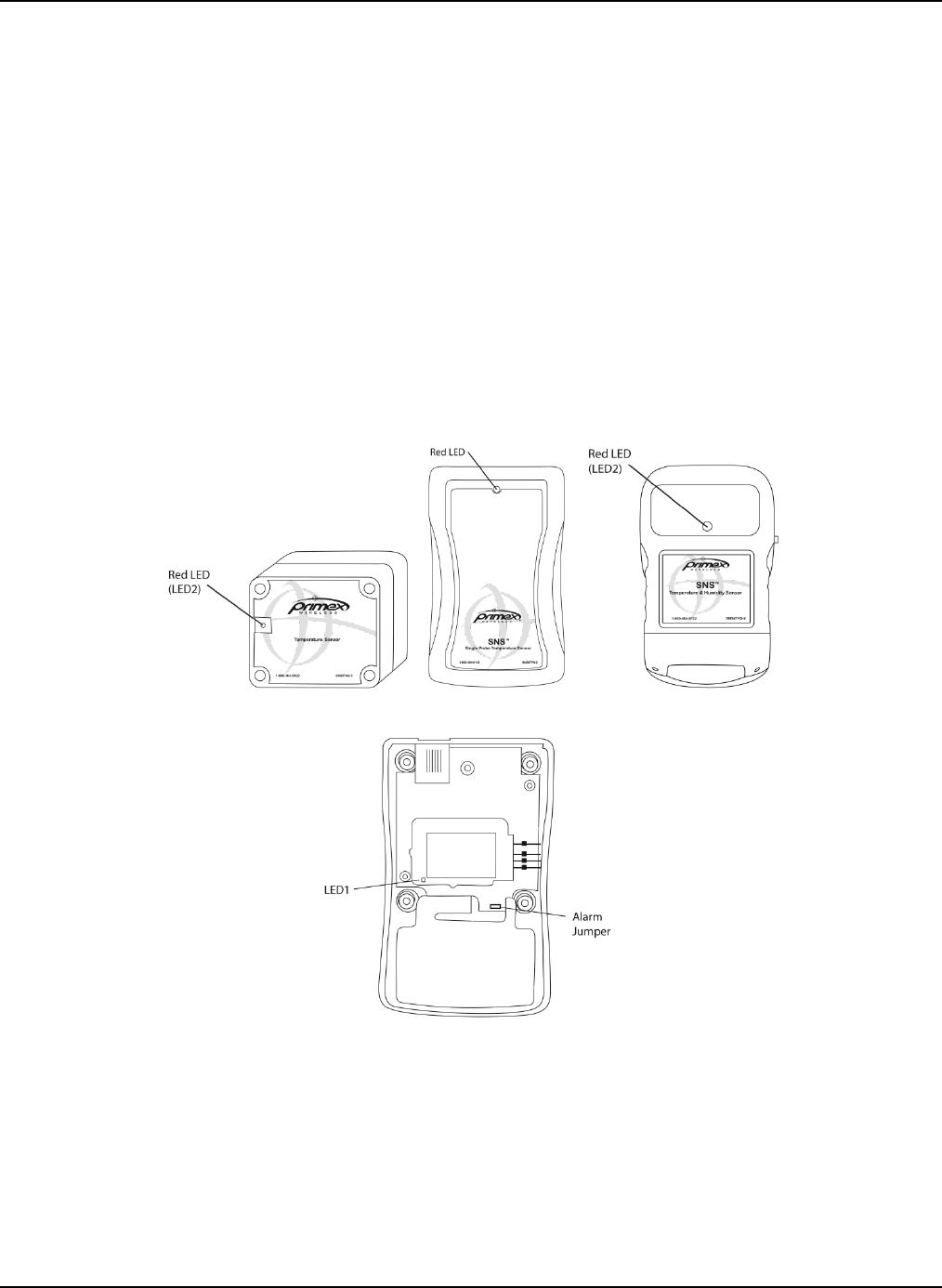
Visual and Auditory Interfaces
LEDs are visual indicators of sensor device status and sensor readings. The sensor device also
communicates its status using beeps.
LEDs
Sensor devices have an LED visible from outside the sensor that indicates sensor status, as shown
in Figure 10. Sensor devices also have an internal LED that may be useful for troubleshooting, as
shown in Figure 4, Figure 11, and Figure 12.
Figure 10: External Red LED Models SNS2TNS-2, SNS2TPS-2, and SNS2THS-2
Figure 11: Inside Model SNS2TPS-2

Features of SNS Battery-powered Sensor Devices Monitoring Thresholds
Primex Wireless, Inc. SNS™ Temperature and Humidity Sensors Installation Guide 22
Figure 12: Inside Model SNS2THS-2
The red LED flashes to alert when the sensor device detects that a threshold that is programmed in
the device has been exceeded. The red LED also indicates that a transmit attempt has just finished.
The internal green LED indicates that the sensor device is connected to a network. When in sensor
mode, the green LED will flash when a connection is made. When in setup mode (the programming
cable is connected to the sensor), the green LED will remain on continuously when a connection is
established. In setup mode, the red LED never comes on.
Beeps
When the service button is pushed, the sensor device beeps.
The sensor device also beeps when monitoring thresholds are set in the sensor device and the
device enters (and exits, depending on the configuration) an alarm state. If you do not want to hear
alarm beeps, remove the alarm jumper. The alarm jumper is located inside the sensor device, as
shown in Figure 4, Figure 11, and Figure 12.
Monitoring Thresholds
During configuration, battery-powered sensor devices permit you to set temperature and humidity
monitoring thresholds in the AMP or in both the AMP and the sensor device itself. In order to
achieve maximum benefit from SNS battery sensors, careful thought should be given to where
alarm thresholds are set as well as the frequency with which sensor devices report readings to the
AMP.
If thresholds are set in the AMP, but not in the sensor device, the alarm state is not detected until
the sensor device transmits scheduled readings to the AMP and the AMP recognizes that a reading
is out of limits. Depending on how frequently the sensor device is configured to transmit readings to
the AMP, a period of time may elapse before the AMP creates an alert for the out-of-range
condition.
If thresholds are set in the sensor device and these thresholds are exceeded or, depending on the
configuration, exceeded for a period of time, the sensor device enters an alarm state and transmits
readings to the AMP. However, thresholds set in the sensor device can only be changed on a
device-by-device basis through reconfiguration.

Features of SNS Battery-powered Sensor Devices Operational Sequences
Primex Wireless, Inc. SNS™ Temperature and Humidity Sensors Installation Guide 23
Set Monitoring Thresholds to Prevent Loss of Sensitive Assets
If you have sensitive assets such as blood, medications, or tissues, you can set up the sensor
devices to report readings as many as 15 times per hour and to generate alerts and send
notifications as soon as thresholds are reached.
Be sure that settings are configured both in the sensor device and in the AMP sensor device page.
In this scenario, you will set the sensor’s transmit period to a shorter time, and edit the sensor
device’s reporting period to the same number of minutes as the transmit period.
Note: Shorter transmit periods (more frequent transmissions) shorten battery life
and increase network load.
Then, you will use the Battery Sensor Software Configuration utility to set the transmit period in the
sensor devices. You will also set the alarm thresholds in the sensor device. If the sensor device
detects that a threshold has been exceeded the LED will flash and the sensor will transmit a
reading to the AMP, where an alert will be active. See Appendix B: Battery Sensor Configuration
Utility on page 57 for instructions on setting these alarm thresholds.
Note: Thresholds configured in the sensor device using the Battery Sensor
Software Configuration utility can only be changed using the utility. If you
relocate the sensor device, for example, moving it from a refrigerator to a
freezer, you will need to reconfigure the device using the utility.
Operational Sequences
Turn on the Sensor Device
Place the on/off switch in the ‘on’ position to turn on the sensor device.
Normal Operation
When the USB Programmer is not plugged into the sensor and the sensor is powered on, the
sensor is in Sensor mode. The sensor spends most of its time in this mode in a very low power
state (sleep). When a transmit period is due, it powers up the Wifi radio, attempts to link to the
specified wireless network, transmits its data and then goes back to sleep.
The sensor transmits based on a transmit period or entering an alarm state. The sensor will go
through following steps in order to connect to a network and deliver data:
1. Associate
2. Authenticate (depends on the type of security)
3. Request IP from DHCP Server (if set to dynamic IP)
4. Request from Name Server IP address of hostname (if a hostname is used for the Destination
address and DNS Server specified).
5. Sensor sends UDP packet with sensor data.
6. Host sends UDP acknowledgement packet.
Check-in with the AMP
The sensor will initiate a delivery attempt to the AMP, known as a ‘try’, repeatedly (typically every
30 seconds) until either an acknowledgement is received from the host or the number of tries has
been exhausted. If no acknowledgement is received, the sensor device will stop transmitting and
wait for the next transmit period or when an alarm is triggered. The sensor follows this delivery
mechanism for both when the transmit period arrives or for alarm attempts.

Features of SNS Battery-powered Sensor Devices Operational Sequences
Primex Wireless, Inc. SNS™ Temperature and Humidity Sensors Installation Guide 24
When specifying the setup parameters for a sensor, you must give careful consideration to the
needs of your application and battery life. The more often the sensor transmits data because of the
transmit period, alarms, or retries, the shorter the battery life. It is recommended that you use the
alarm function to transmit sensor data of concern and extend the transmit period to lengthen the
battery life of the sensor. If you plan on using DHCP or DNS, it is best to use local DHCP and DNS
servers rather than a DNS Server on the internet. The local servers will give better response times
compared to the remote servers and thus conserve battery life.
Setup Mode
If the USB Programmer is connected to the sensor, the sensor is in Setup mode. When in Setup
mode and configured properly, the sensor attempts to connect to the network and will remain
connected to the network. The sensor will not send sensor data when in this mode.
Handle Alarms
If alarms are configured in the sensor device, pressing the button cancels the alarm on the sensor
device.
Change Batteries
The sensor device has a built-in battery meter. This meter is based on a count of the sensor device
transmissions. This battery information is only an estimate of the remaining battery life. The Battery
Sensor Configuration Utility shows the estimated battery expiration and the estimated battery life
percentage in the Status page. Refer to Figure 22: SNS Battery Sensor Configuration Utility Status
Tab on page 44 and Table 14: SNS Battery Sensor Configuration Utility Status Tab Fields and
Values on page 45.
When changing batteries, be sure to replace both batteries and reset the battery. See Replace
Batteries in Battery-powered Sensor Devices on page 49.

Primex Wireless, Inc. SNS™ Temperature and Humidity Sensors Installation Guide 25
Configure Sensors for the Network
Regardless of the type of sensors deployed in your SNS Temperature and Humidity sensor
network, each sensor device must be configured with the settings of the wired or wireless network
in which it will be used. This section covers the following topics:
• Select the Configuration Method
• Edit Default Sensor Profiles
• Configure AC-powered Sensors using Discovery and Auto-Configuration
• Set up the Network Connection
• Configure AC-powered Sensors using Browser-based Configuration
• Configure Battery-powered Sensors with the Sensor Configuration Utility
Select the Configuration Method
Several methods exist to configure sensor devices. The configuration method you choose depends
on several factors such as the type of sensor and the availability of the network at the time of
configuration. Table 7 shows the applicability of each method. All methods assume that the sensor
is configured with the latest Primex Wireless firmware and that the Default Profile has been set up
on the AMP. For information on the Default Profile, see Edit Default Sensor Profiles on page 25.
Table 7: Sensor Configuration Methods
Configuration Method Supported Sensors Does NOT Support Requirements
Discovery and Auto-
Configuration AC-powered Sensors Battery-powered
Sensors SNS AMP has been installed and
you have a network connection
available on the same subnet that
the AMP is on.
Browser-based
Configuration AC-powered Sensors Battery-powered
Sensors Direct connection to a laptop.
Laptop must be DHCP enabled or
use a static IP on the 192.168.1.x
network excluding 192.168.1.1 with a
subnet mask of 255.255.255.0.
Sensor Configuration
Software Tool Battery-powered
Sensors
AC-powered Sensors Battery-powered sensor
configuration utility is installed and
you can connect the USB
programming cable to the computer.
To verify that sensor devices can
connect, need to be within range of
wireless network with the AMP.
Edit Default Sensor Profiles
The Sensor Device Default Profiles page lists the default sensor profiles that the AMP has available
for various sensor models. The Sensor Default Profile includes the network and time interval
settings for sensors on your network as well as default ranges that the sensor will monitor. For AC-
powered sensors, the default profile is downloaded to the sensors during configuration or when
sensors check in with the AMP. For battery-powered sensors, in which the configuration is set
Configure Sensors for the Network Edit Default Sensor Profiles
Primex Wireless, Inc. SNS™ Temperature and Humidity Sensors Installation Guide 26
directly in the sensor, the Sensor Default Profile is used to create the AMP information for each
device.
The first step in configuring sensors is to edit the Sensor Default Profile for your sensor model.
Table 8 shows which default profile to edit for each sensor model.
Note: To edit the Sensor Default Profile, you must be logged in to the SNS AMP as a
user with the Sensor Admin role.
Table 8: Sensor Model Default Profiles
Sensor Model Default Profile
Single Channel AC-powered Temperature Sensor (SNSATPS,
SNSCTPS, SNSGTPS) AC Single Probe Temperature
Dual Channel AC-powered Temperature Sensor (SNSATPD,
SNSCTPD, SNSGTPD) AC Dual Probe Temperature
AC-powered Temperature and Humidity Sensor (SNSATHX,
SNSCTHX, SNSGTHX) AC Temperature & Humidity
Temperature Sensor, Dual Battery (SNS2TPS-2) Temperature (RTD or Sealed)
Temperature Sensor, Dual Battery, Dual Channel (SNS2TPD-2) Dual Probe Temperature (RTD)
Sealed Temperature Sensor, Dual Battery (SNS2TNS-2) Temperature (RTD or Sealed)
Temperature and Humidity Sensor, Dual Battery (SNS2THS-2) Temperature and Humidity
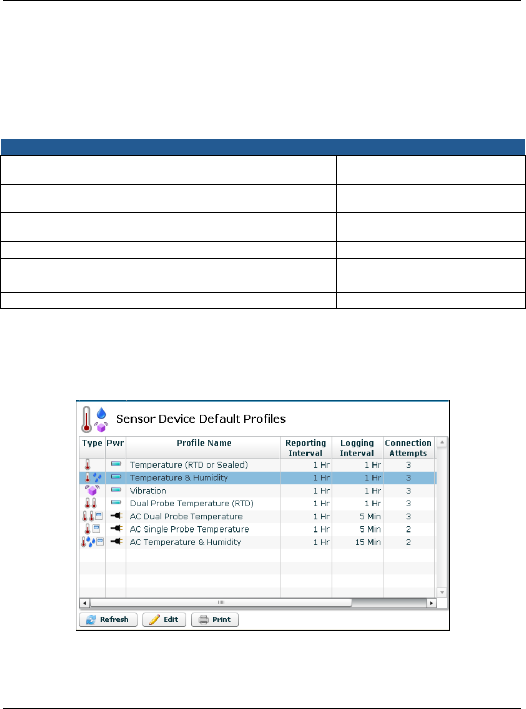
Editing the Sensor Device Default Profile
1. From the AMP Dashboard, select Sensors > Default Profile. The Sensor Device Default
Profiles page appears.
Figure 13: Sensor Device Default Profiles Page
2. To change the settings for the profile, select the profile for your sensor model from the list
and click Edit. Refer to Table 8 for the default profile for your sensor model. You will see the
Edit Default Profile dialog box for the default profile.
Configure Sensors for the Network Edit Default Sensor Profiles
Primex Wireless, Inc. SNS™ Temperature and Humidity Sensors Installation Guide 27
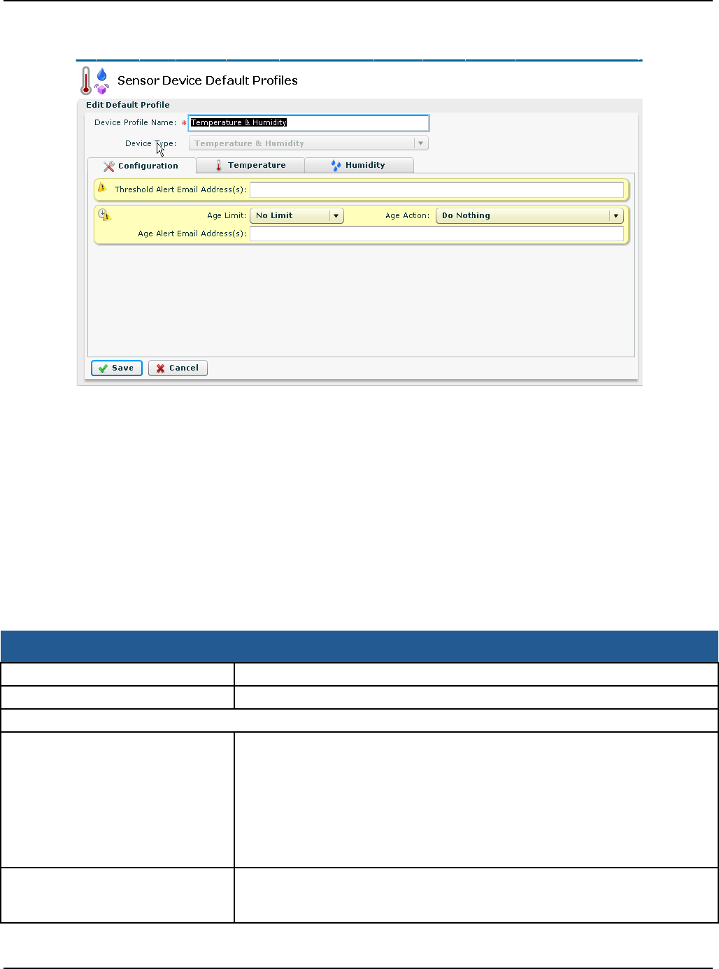
Figure 14: Sensor Device Default Profiles Page for the Battery-powered Temperature and Humidity Sensor
3. Enter the profile information on the tabs appropriate to the default profile. For a description
of the fields, see Table 9.
Note: If the Network Settings are blank, this means that they have not been set up
in the SNS AMP software. For information on configuring the AMP
software, refer to the SNS AMP Installation and Administration Guide.
4. Click Save. The Sensor Device Default Profiles page reappears.
Sensor Device Default Profile Settings
Table 9 describes the Default Profile settings for all default profiles. The fields you see in the AMP
depend on the default profile you are editing.
Table 9: Sensor Device Default Profile Fields and Values
Note: Items marked with an asterisk ‘*’ are mandatory.
Item Description
*Device Profile Name The name of the device default profile.
Device Type The type of sensor device.
Configuration Tab Fields and Values
Out-of-Range Email Address(s) Enter one or more email addresses (maximum 500 characters) separated
by semi-colons for the AMP to send notifications if conditions monitored by
the sensor exceed the specified threshold. High Threshold, Low Threshold,
High Span Exceeded, or Low Span Exceeded alerts must be enabled in
order for the AMP to send the Out-of-Range notification. This user receives
email in addition to anyone whose email address is defined for the specific
alerts. Out-of-Range Email notification is generally sent to on-call
pager/email, e.g., helpdesk or security.
Enable Audio Alert Enable (check) the Enable Audio Alert checkbox to instruct the device to
sound the buzzer when in an alarm state. (AC-powered sensor devices
only)

Configure Sensors for the Network Edit Default Sensor Profiles
Primex Wireless, Inc. SNS™ Temperature and Humidity Sensors Installation Guide 28
Item Description
Audio Reset Period Interval from the time the alarm is cleared at the device by pressing the
service button before the device again displays the alarm if the alarm
condition persists. At the end of the Audio Reset Period the LED will begin
to flash again if the alarm condition persists, even if Enable Audio Alert is
disabled (unchecked).
Your choices are:
Indefinite
15 or 30 minutes
1, 2, 3, 4 hours
(AC Single and Dual Probe Temperature sensor devices only)
Not Reporting Limit Maximum time that the sensor can go without checking in with the AMP
before notification is sent. If this setting is exceeded, the AMP generates
the Not Reporting alert if this alert is enabled.
Your choices are:
No Limit; 30 minutes; 1 Hour; 2 Hours; 3 Hours; 4 Hours; 6 Hours; 8 Hours;
12 Hours; 16 Hours; 1 day
Not Reporting Email Address(s) Enter one or more email addresses (maximum 500 characters) separated
by semi-colons for the AMP to send notifications if the Not Reporting Limit
is exceeded. The Not Reporting alert must be defined in order for the AMP
to send the Not Reporting notification. This user receives email in addition
to anyone whose email address is defined for the specific alerts. Not
Reporting notification is generally sent to the IT person who can repair,
replace or reprogram the sensor device.
Reporting Interval This field indicates how often the sensor device reports status to the AMP.
Your choices are:
Every: 4, 5, 10, 15, 20, 30 minutes, 1, 2, 4, 8, 12 hours
Note: For battery-powered sensors, this should be the same as the
Transmit Period configured in the sensors.
Note: AC-powered sensors (and battery-powered sensors with internally
configured alarms) also report to the AMP when a threshold or span is
exceeded or if the temperature comes back into range. AC sensors also
check in with the AMP if power is lost and then restored. All sensors check-
in with the AMP if the service button is pushed by the user during normal
operation.
Logging Interval This field indicates how often the sensor device saves its readings, and is
separate from the interval at which the device accesses the network to
report readings. If the logging interval is enabled in the sensor and set
shorter than the reporting (transmit) interval, the sensor device will report
multiple readings per check-in, but will check in less frequently for the same
amount of data, thus saving the battery life.
(Battery-powered sensor devices only)
Connection Attempts Choose the number of attempts, 1-5, the device makes to connect to the
AMP for its regularly scheduled reporting. If the device fails to connect after
this number of attempts, it waits until its next regularly scheduled report
time.
(Battery-powered sensor devices only)

Configure Sensors for the Network Edit Default Sensor Profiles
Primex Wireless, Inc. SNS™ Temperature and Humidity Sensors Installation Guide 29
Item Description
Temperature, Temperature 1, and Temperature 2 Tabs Fields and Values
*Reading Name Enter a name for the reading from the temperature probe attached to this
device in the Reading Name field.
Temperature Units Choose the units of measure to be used for the temperature reported by
this sensor, either Celsius or Fahrenheit
Max. Graph Value Enter the maximum temperature value you want displayed when data from
this sensor is graphed in the Sensor Readings page. You can override
these values while viewing the graph and set the graph to auto-scale, but
any exports to Excel will always use the configured Max value.
Min. Graph Value Enter the minimum temperature value you want displayed when data from
this sensor is graphed in the Sensor Readings page. You can override
these values while viewing the graph and set the graph to auto-scale, but
any exports to Excel will always use the configured Min value.
High Temperature Threshold
In the High Temperature Threshold, enter a value in degrees for the
temperature () at which the measured temperature exceeds the
maximum allowed temperature. Going above this value triggers an alarm. If
you configure a high temperature limit but not a span, when the limit is
crossed the sensor device notifies the AMP. (AC-powered sensors also
begin flashing the red LED and sounding the buzzer, if it is configured to
sound.)
Note: If you are concerned with exceeding a high threshold, only set the
high threshold and leave the low threshold blank. Entering any value in a
threshold field causes the sensor to report a reading for that field which
unnecessarily drains the battery and may degrade performance of the
AMP.
High Span Minutes The amount of time that the temperature needs to be above the high limit
before an alarm is triggered. In the High Span Minutes field, enter a number
of minutes to define the high span for this sensor reading. If the
temperature remains above the High Temperature value for more than this
number of minutes, or the last known reading is older than the high span
minutes, a high span event has occurred. The span should not be less than
the reporting interval. (AC-powered sensors also begin flashing the red
LED and sounding the buzzer, if it is configured to sound.) Leaving this field
blank will cause an alarm to trigger immediately when the high threshold is
reached.
Low Temperature Threshold
In the Low Temperature field, enter a value in degrees for the temperature
() at which the measured temperature falls below the minimum allowed
temperature. Dropping below this limit triggers an alarm. If you configure a
low temperature limit but not a span, when the limit is crossed the sensor
device notifies the AMP. (AC-powered sensors also begin flashing the red
LED and sounding the buzzer, if it is configured to sound.)
Note: If you are concerned with exceeding a low threshold only set the low
threshold and leave the high threshold blank. Entering any value in a
threshold field causes the sensor to report a reading for that field which
unnecessarily drains the battery and may degrade performance of the
AMP.

Configure Sensors for the Network Edit Default Sensor Profiles
Primex Wireless, Inc. SNS™ Temperature and Humidity Sensors Installation Guide 30
Item Description
Low Span Minutes The amount of time that the temperature needs to be below the low limit
before an alarm is triggered. In the Low Span Minutes field, enter a
number of minutes to define the low span for this sensor reading. If the
temperature remains below the Low Temperature value for more than this
number of minutes, or the last known reading is older than the low span
minutes, a low span event has occurred. The span should not be less than
the reporting interval. (AC-powered sensors also begin flashing the red
LED and sounding the buzzer, if it is configured to sound.) Leaving this field
blank will cause an alarm to trigger immediately when the low threshold is
reached.
Humidity Tab Fields and Values (Temperature & Humidity Sensors Only)
Reading Name Enter a name for the reading from the humidity probe in the Reading Name
field.
Max. Graph Value Enter the maximum humidity value you want displayed when data from this
sensor is graphed.
Min. Graph Value Enter the minimum humidity value you want displayed when data from this
sensor is graphed.
High Humidity Threshold
.
In the High Temperature field, enter a value for the humidity () at which
the measured humidity exceeds the maximum allowed humidity.
High Span Minutes
.
In the High Span Minutes field, enter a number of minutes to define the
high span for this sensor reading. If the humidity remains above the High
Humidity value for more than this number of minutes, or the last known
reading is older than the high span minutes, a high span event has
occurred. The span should not be less than the reporting interval.
Low Humidity Threshold
.
In the Low Humidity field, enter a value in degrees for the humidity () at
which the measured humidity falls below the minimum allowed
temperature.
Low Span Minutes
In the Low Span Minutes field, enter a number of minutes to define the low
span for this sensor reading. If the humidity remains below the Low
Humidity value for more than this number of minutes, or the last known
reading is older than the high span minutes, a low span event has
occurred. The span should not be less than the reporting interval.
Network Settings Fields and Values (AC-powered Sensors Only)
Note: Discovery and Auto-Configuration uses DHCP. After configuring the sensor device, you can edit its
settings to assign it a static IP address. If DHCP is not an option, configure sensors using Browser-based
Configuration and add the sensor device on the AMP with a static IP address before configuring it.
*Access AMP Using: (Device Settings) You may access the AMP via an internal or external IP
address.
Internal IP address
External IP address
AMP Alternate 1 (Optional) Select an alternate access method: Internal or External IP
address.
AMP Alternate 2 (Optional) Select an alternate access method: Internal or External IP
address.

Configure Sensors for the Network Configure AC-powered Sensors using Discovery and Auto-Configuration
Primex Wireless, Inc. SNS™ Temperature and Humidity Sensors Installation Guide 31
Item Description
Message Retries Sensors use UDP (User Datagram Protocol) to communicate with the AMP
server. UDP does not provide guaranteed delivery, so the sensors can be
set to retransmit unacknowledged messages from 1 to 4 additional times
before giving up and saving the data to report the next time the sensor
connects to the network.
Retry Period Sensors can be configured to wait from 5 to 60 seconds before trying to re-
send an unacknowledged message to the AMP. Typically 5 seconds is
more than sufficient, but longer wait periods can be used if desired on
networks with bursts of high activity.
Wireless Network Settings 1 Each sensor device can be configured to use up to three different wireless
network settings, allowing for backups and fail-over scenarios. If using a
wireless network, the first network setting is required.
Select from the list of networks configured for the AMP.
Wireless Network Settings 2 For the optional, alternate wireless network, select from the list of networks
configured for the AMP.
Wireless Network Settings 3 For the optional, alternate wireless network, select from the list of networks
configured for the AMP.
Configure AC-powered Sensors using Discovery and Auto-Configuration
Discovery and Auto-Configuration is the preferred method for configuring AC-powered sensor
devices. During Discovery and Auto-Configuration, you connect the sensor device to the network.
The MAC address of the sensor device is transferred to the AMP, and the AMP downloads the
Default Profile as the information by which the device operates as part of the network. If the SNS
AMP has been installed and you have a network connection available on the same subnet that the
AMP is on, you can use Discovery and Auto-Configuration to configure AC-powered sensors.
Note: Discovery and Auto-Configuration assumes that sensor devices connect to the
network using DHCP. After sensor devices are recognized on the AMP, you can
edit the network settings for each sensor device to assign it a static IP address. If
DHCP is not an option, configure sensors using Browser-based Configuration and
add the sensor device on the AMP with a static IP address before configuring it.
Otherwise, when the sensor checks in after being configured, the AMP will see it
as an “unknown” new sensor and will use the default profile to configure it, which
will wipe out the static IP address configured in the sensor. See the SNS
Temperature and Humidity Sensors User Guide for information on editing a
sensor device.
Guidelines
Before you begin be sure that the following items are available:
• Default Profile configured for your network on the AMP. See Edit Default Sensor Profiles on
page 25.
• A network connection on the same subnet as the AMP
• Ethernet cable

Configure Sensors for the Network Set up the Network Connection
Primex Wireless, Inc. SNS™ Temperature and Humidity Sensors Installation Guide 32
Configuring AC-powered Sensors Using Discovery and Auto-Configuration (Same Subnet as
the AMP)
1. Connect the temperature probe to the sensor in the available Sensor Probe jack.
2. Connect one end of the Ethernet cable to the RJ45 port on the side of the sensor device, as
shown in Figure 2. Connect the other end of the Ethernet cable to the network on the same
subnet as the AMP.
3. Plug the AC adapter for the sensor device into a power source.
4. Plug the AC adapter into the sensor device. The sensor device will display all the segments
and then go blank briefly before displaying the temperature.
5. When the sensor display shows the temperature, push and immediately release the button
on the front of the sensor. The sensor will emit a series of beeps. The beeps signal the
following connection sequence: 1= radio booted, 2 = connected to network, 3 = connected to
the AMP.
6. Check the AMP to confirm that the sensor device has checked in. The sensor device
appears in the Sensor Devices list with the MAC address in brackets in the Name column.
Double-click on the sensor device in the Sensor Devices list to edit information for the
sensor, for example, change the name to something meaningful. Refer to the SNS
Temperature and Humidity Sensors User Guide for details on editing sensor device
information on the AMP.
7. Disconnect the Ethernet cable from the sensor.
8. The Sensor Default Profile is stored in the sensor’s non-volatile memory, so you can unplug
and move the sensor device to its installation location.
Note: Verify that the first sensor device you configure checks in with the AMP with the
correct settings before configuring additional sensors. The first sensor device
does not check in or the settings are not correct, troubleshoot the problem or
correct the default profile before configuring additional sensors.
Set up the Network Connection
During Browser-based Configuration, the AC-powered sensor device must communicate with your
computer. Follow these steps to prepare your computer to communicate AC-powered sensor
devices.
Setting up the Network Connection
1. From the Windows Start button, select Settings>Control Panel>Network Connections. A
Network Connections window, similar to Figure 15, opens with LAN or High-Speed Internet
information.
Configure Sensors for the Network Set up the Network Connection
Primex Wireless, Inc. SNS™ Temperature and Humidity Sensors Installation Guide 33
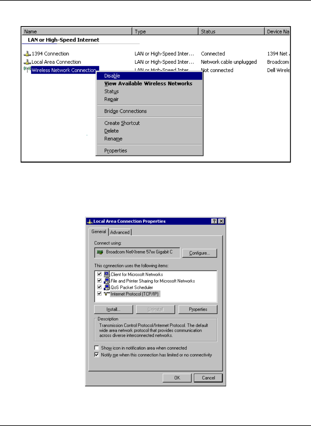
Figure 15: Network Connections Window
2. If your computer has a wireless network card, right-click the Wireless Network Connection
item and choose Disable on the context menu displayed.
3. Right-click the Local Area Connection item and choose Properties on the context menu.
You will see the Local Area Connection Properties dialog box, as shown in Figure 16.
Figure 16: Local Area Connection Properties Dialog Box
Configure Sensors for the Network Configure AC-powered Sensors using Browser-based Configuration
Primex Wireless, Inc. SNS™ Temperature and Humidity Sensors Installation Guide 34
4. On the General tab under “This connection uses the following items” list, select the Internet
Protocol (TCP/IP) item, and then click the Properties button. You will see the Internet
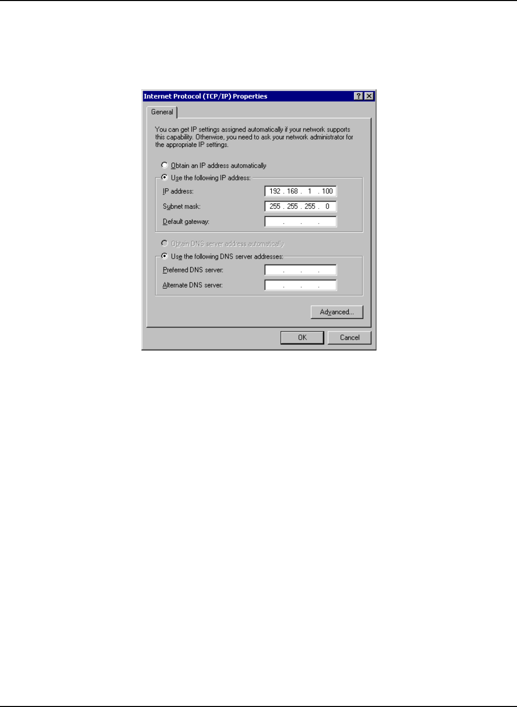
Protocol (TCP/IP) dialog box, as shown in Figure 17.
Figure 17: Internet Protocol (TCP/IP) Properties
5. Choose the Use the following IP address option button, and enter the following
information:
• In the IP address field, enter 192.168.1.100.
• In the Subnet Mask field, enter 255.255.255.0.
6. Click the OK button to accept the IP address changes and return to the Local Area
Connection Properties dialog box.
7. Again, click the OK button to accept the changes, close the dialog box, and return to the
Network Connections window.
8. Close the Network Connections window.
You are now ready to physically connect the AC-powered sensor device to the computer for
browser-based configuration.
Configure AC-powered Sensors using Browser-based Configuration
In the event that you cannot connect the sensor to the network on the same subnet as the AMP, for
example, if you are configuring sensors for use in a newly constructed building without a network, or
you are configuring the sensors at a maintenance facility not on the network, you can use Browser-
based Configuration to configure AC-powered sensors. When a sensor is configured using
Browser-based Configuration, you connect the sensor to a laptop and use the sensor’s web server
to enter information for the sensor to connect to the SNS AMP. Later, when the network is available
and the AMP is installed, you connect the sensor to the network and force it to check in with the
AMP.

Configure Sensors for the Network Configure AC-powered Sensors using Browser-based Configuration
Primex Wireless, Inc. SNS™ Temperature and Humidity Sensors Installation Guide 35
Note: During this check in, the Default Profile on the AMP will overwrite the settings that
you have configured, so before beginning Browser-based Configuration, you first
set up the Default Profile on the AMP.
For additional information on the Browser-based Configuration Tool, see Appendix A: Browser-
based Configuration Tool on page 54.
Important
• Do not change the Port settings.
• Be sure that the Default Profile on the AMP has been configured for your network.
• When opening the sensor web configuration page, you may need to disable your laptop or PC’s
wireless radio to avoid connecting to other devices with this address.
• Obtain the following network information for use when configuring devices for the wireless
network.
• Wireless network settings: SSID, Security Type, Security Key
• Static IP Address, if not using DHCP. If using Static IP, you will need the IP Address,
Subnet Mask, and Gateway. When using Static IP, you must specify the IP address of
the NTP server numerically. For example, you must enter 10.10.39.100, not
ntp.primexwireless.com.
Note: If you are not familiar with the network settings, contact your network
administrator.
Configure the Sensor
While in configuration mode, you will use the SNS Configuration Screen, Figure 18, to configure the
device for your wireless network.
Configuring an AC-powered Sensor
1. Connect the temperature probe(s) to the sensor in the available Sensor Probe jack(s).
2. Connect an Ethernet cable between the sensor’s Ethernet port, shown in Figure 2, and the
PC Ethernet port.
3. Plug the AC adapter into a power source.
4. Hold down the blue button on the front of the sensor while connecting the AC adaptor to the
sensor. Release the button when the sensor displays “Con”, indicating that it is in
Configuration Mode. When the PC recognizes the sensor, the sensor beeps.
5. Open a browser on the PC and browse to the sensor device’s web address at
http://192.168.1.1. Wait 30 to 60 seconds for the sensor device to establish a connection
with the PC.
6. When prompted for a login, enter:
Username = admin
Password = admin
The SNS Configuration page appears, as shown in Figure 18.
Configure Sensors for the Network Configure AC-powered Sensors using Browser-based Configuration
Primex Wireless, Inc. SNS™ Temperature and Humidity Sensors Installation Guide 36
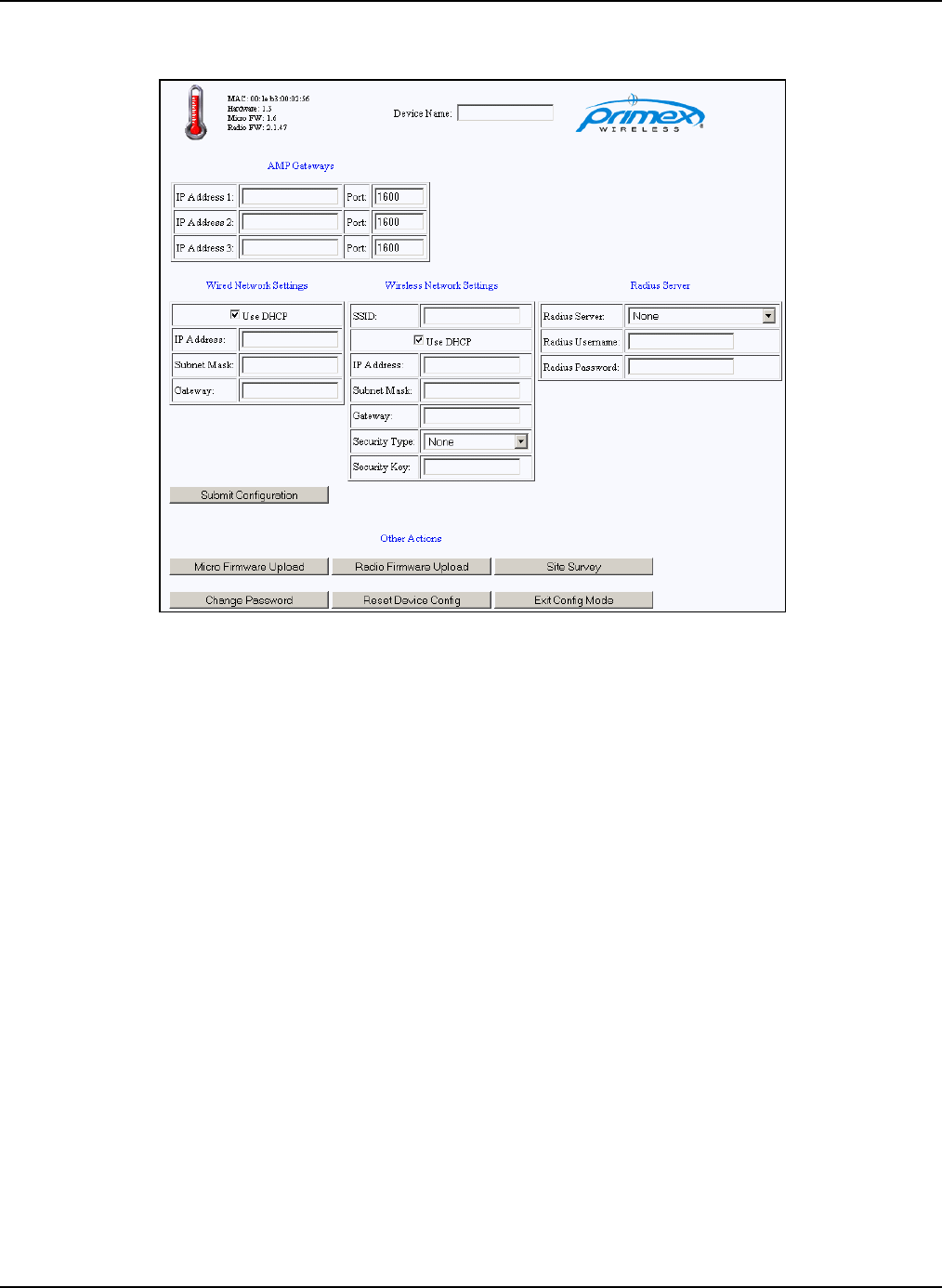
Figure 18: SNS Browser-based Configuration Page: Configuring the Sensor for the Network
7. On the Configuration page, enter your network settings in the fields provided. Table 10
describes the network settings.
8. Click the Submit Configuration button to apply the settings.
9. When the screen indicates that configuration is finished, click Return to Main and Exit
Config Mode. The sensor will beep three times.
10. Disconnect the Ethernet cable from the sensor and PC.
11. Quickly depress then release the blue button (once) on the front panel of the sensor. The
unit will quickly “beep” two times.
12. After approximately 45 seconds, another beep indicates connection with the SNS AMP.
If this is a new sensor, the sensor will download the Default Profile. If it’s an existing sensor,
then the sensor checks for configuration changes on the AMP and updates thresholds,
reporting intervals, and other settings.
You can now use the AMP to view the readings reported by the sensor and adjust the sensor’s
reporting thresholds. For more information, refer to the SNS Temperature and Humidity Sensors
User Guide.

Configure Sensors for the Network Configure AC-powered Sensors using Browser-based Configuration
Primex Wireless, Inc. SNS™ Temperature and Humidity Sensors Installation Guide 37
Table 10: Network Settings Fields and Values
Item Description
Device Information
The following information about the device you’re accessing is displayed in the top
left corner of the main page.
Icon: The icon displayed represents the type of device you’re accessing. The icon of
a thermometer means the device is a temperature sensor.
MAC: A twelve (12) character hexadecimal Media Access Control (MAC) address
which is a globally unique identifier of the 802.11 wireless radio in the device.
Hardware: The version number of the device hardware you’re accessing.
Micro FW: The version number of the firmware currently installed in the
microcontroller of the device you’re accessing.
Radio FW: The version number of the firmware currently installed in the radio of the
device you’re accessing.
Device Name Enter a device name in the Device Name field. This is the name that will be
displayed for the device when it’s accessed by Primex Wireless’s AMP software.
AMP Gateways Use the IP address and port fields to specify up to three AMP gateways you want
this device to use.
IP Address 1 is the default AMP gateway your device will use. If the AMP gateway
at IP Address 1 is not available, the device will next attempt to use the AMP
gateway at IP Address 2 followed by the AMP gateway at IP Address 3.
Wired Network Settings In addition to wireless networking, Primex Wireless devices have an RJ-45
connector and can be put on the network via regular network cabling. The following
controls specify how this device should connect to a wired network.
Use DHCP: Enable (check) the Use DHCP checkbox to instruct the device to use
DHCP to assign an IP address to the device.
IP Address: Enter an IP address in the IP Address field if you want to assign a fixed
IP address to the device. Note: Leave this field blank if you’ve checked the Use
DHCP checkbox.
Subnet Mask: The subnet mask for your network. This entry must be blank, or a
valid IPv4 subnet mask. Note: Leave this field blank if you’ve checked the Use
DHCP checkbox.
Gateway: The IP address of the gateway for your network. This entry must be blank,
or a valid IPv4 address. Note: Leave this field blank if you’ve checked the Use DHCP
checkbox.

Configure Sensors for the Network Configure AC-powered Sensors using Browser-based Configuration
Primex Wireless, Inc. SNS™ Temperature and Humidity Sensors Installation Guide 38
Item Description
Wireless Network
Settings The following controls specify how this device should connect to a wireless network.
SSID: The Service Set Identifier (SSID) is a code which identifies a wireless network.
Use DHCP: Enable (check) the Use DHCP checkbox to instruct the device to use
DHCP to assign an IP address to the device.
IP Address: Enter an IP address in the IP Address field if you want to assign a fixed
IP address to the device. Note: Leave this field blank if you’ve checked the Use
DHCP checkbox.
Subnet Mask: The subnet mask for your network. This entry must be blank, or a
valid IPv4 subnet mask. Note: Leave this field blank if you’ve checked the Use
DHCP checkbox.
Gateway: The IP address of the gateway for your network. This entry must be blank,
or a valid IPv4 address. Note: Leave this field blank if you’ve checked the Use DHCP
checkbox.
Security Type: A selection from the list of supported security modes, or the None
selection if the network is an open network with no security.
Security Key: A security key from 0 to 64 characters. If WEP is selected, the
Security Key must be a Hexadecimal Pre Shared Key. If WPA or WPA2 is selected,
the Security Key must be an ASCII Passphrase as long as it is from 8 to 63
characters long. If it is 64 characters long, the key must be a hexadecimal Preshared
key.
Note: Leave this field blank if you’ve selected the None selection for the Security
Type.
Radius Server The following controls specify how this device connects to a Radius server.
Radius Server: Select the type of Authentication to be used.
Radius Username: A 1 to 40 character username used to log in to the RADIUS
server. Leave this field blank if you’ve selected “None” as the Radius Server.
Radius Password: A 1 to 40 character password used to log in to the RADIUS
server. Leave this field blank if you’ve selected “None” as the Radius Server.

Configure Sensors for the Network Configure Battery-powered Sensors with the Sensor Configuration Utility
Primex Wireless, Inc. SNS™ Temperature and Humidity Sensors Installation Guide 39
Configure Battery-powered Sensors with the Sensor Configuration Utility
Battery-powered sensors must be configured using the Sensor Configuration Utility. The following
tasks are involved in configuring battery-powered sensors:
• Install the Sensor Configuration Utility on your laptop. The Primex Wireless Sensor
Configuration Utility can be found on the SNS Resource CD shipped with your product. Please
install the Primex Wireless Configuration Utility before continuing. For installation instructions
and additional information about the Sensor Configuration Utility, see Appendix B: Battery
Sensor Configuration Utility on page 57.
• Connect the sensor to the laptop and use the Sensor Configuration Utility to upload network
settings to the sensor.
• Name and save configuration settings for each type of sensor that you will be
configuring.
• After configuring the first sensor of each type, check that the sensor can check into the
AMP and troubleshoot any connection issues, updating the configuration settings if
necessary. You can then configure additional sensors of each type using the saved
settings.
• Perform the configuration steps in the order below. Complete all procedures.
• View and edit each battery-powered sensor on the AMP using the AMP Sensors module.
• Later, after you install the sensor device in its permanent location, you verify that it is on the
network by forcing it to check in with the AMP.
Configuring Network Settings for Battery-powered Sensors
1. Turn on the sensor. Ensure that the sensor device is on for at least 5 seconds. For the
location of the On/Off switch, see Features of SNS Battery-powered Sensor Devices on
page 18.
2. Plug the USB Programming cable into the computer. The computer may display a pop-up
message stating that new hardware has been found.
3. Start the SNS Sensor Configuration Utility.
Note: The software will not work properly unless the USB Programmer is plugged
into the computer before the software is launched.
4. Connect the USB Programming cable to the sensor device. The USB Programming port is in
different locations on each sensor model, as shown in Figure 4, Figure 6, and Figure 7.
IMPORTANT: Do not connect the USB Programmer into the sensor’s
configuration port unless the USB Programmer is connected to a
computer USB port.
5. In the SNS Sensor Configuration Utility, click the Retrieve button to identify the type of
sensor. The Sensor Configuration Utility will identify the sensor and adjust the number and
type of fields for the specific type of sensor. You will see a message stating that the sensor
parameters have been retrieved and the type of sensor in the upper right of the Setup tab.
6. In the Setup tab, select the Network tab, as shown in Figure 19. The Setup tab shows
either the current settings of the sensor or the edited settings. The settings information can
be saved.
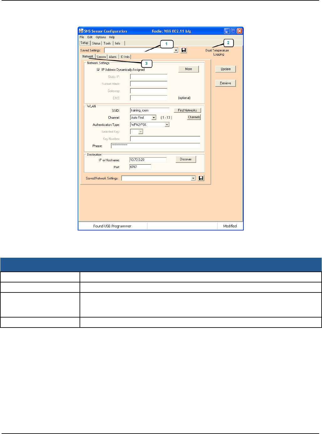
Configure Sensors for the Network Configure Battery-powered Sensors with the Sensor Configuration Utility
Primex Wireless, Inc. SNS™ Temperature and Humidity Sensors Installation Guide 40
Figure 19: SNS Battery Sensor Configuration Utility Network Settings
7. Enter the parameters for the network settings. The settings are described in Table 11.
Table 11: SNS Battery Sensor Configuration Utility Network Settings
Item Description
Update Click the button to send the settings to the sensor.
Retrieve Click the button to gather the settings from the sensor.
Saved Settings (1) Enter the name to describe the settings for a particular sensor device type or select
a name to recall previous saved settings. The setup parameters are saved for a
particular sensor type and cannot be applied directly to another sensor type.
Sensor Type (2)
The utility displays the current sensor type in the upper right corner of the Setup tab.

Configure Sensors for the Network Configure Battery-powered Sensors with the Sensor Configuration Utility
Primex Wireless, Inc. SNS™ Temperature and Humidity Sensors Installation Guide 41
Item Description
Network Tab / Network
Settings (3) IP Address Dynamically Assigned: Check the box if the network will assign an IP
address automatically. Uncheck the box if the IP parameters will be manually
assigned. If unchecked, then the Static IP, Subnet Mask and Gateway fields will
have to be entered.
Static IP: IP address assigned to the sensor. (ex: 192.168.1.55)
Subnet Mask: Subnet mask assigned to the sensor. (ex: 255.255.255.0)
Gateway: Gateway IP address assigned to the sensor. (ex: 192.168.1.1)
DNS: IP address of the Name Server (ex. 192.168.1.254 )
More: The Utility displays the “More Network Parameters” window. These are
advanced parameters read from the sensor as a result of the Retrieve operation.
Described in Table 21: Advanced Options Window on page 67, these parameters
are settable through the Advanced Options menu option and when an Update
operation is performed.
Network Tab / WLAN SSID: Identifier of the wireless channel.
Find Networks: Click this button to display a list of available wireless networks.
From the popup window you can select a network from a list of available networks. If
a network is selected, the utility will populate the SSID, Channel and Security fields
in the Setup tab. Clicking Find Networks selects AutoFind in the Channel field.
Channel: The channel number of the wireless network. The AutoFind option will
cause the sensor to search for up to 3 predefined channels (1, 6, and 11). Note: The
Channel AutoFind feature defaults to search for channels 1, 6 and 11. These
channels are settable in the SNS Sensor Configuration Utility INI file. See Appendix
B: Battery Sensor Configuration Utility on page 57. Note: Do not set the Channel
Auto Find search channels to more than 3 channels. This will have an effect on
sensor range and battery life.
Channels Button: The Channels button is displayed only when the Channel field is
set to “Auto Find”. The utility will display the “Select Auto Find Channels” window.
Select the channel you use or the 3 that you use. Channels 1, 6, and 11 are most
commonly used. Setting all channels will increase battery use due to increased
scanning.
Authentication Type: The current Authentication type: None, WEP-128, WPA2-
PSK, WPA-TKIP.
Selected Key: (WEP-128 only) The selected key number (1 – 4).
Key Number: (WEP-128 only) The WEP key as 26 character hexadecimal number.
Phrase: (WPA2-PSK) Password phrase or 64 character ASCII-Hex key. If 64
characters are given the sensor will treat the entry as the security key, otherwise the
sensor will generate the key internally from the password phrase.
Network Tab /
Destination IP or Hostname: IP address of the destination host (AMP). The sensor will deliver
its information to this address (ex: 64.39.28.22)
Port: The port number of the destination host. The default is 6767, which is required
for sensor operation. Do not change this.
Discover Button and Window Not currently in use.
Saved Network Settings If you plan to use the same wireless network settings for more than one sensor
device, enter a name into the Saved Network Settings field and click the Save button
to save the current network settings. You can later apply the network settings to
other sensors or create other network settings files and then recall them by selecting
the down arrow and selecting the desired network.
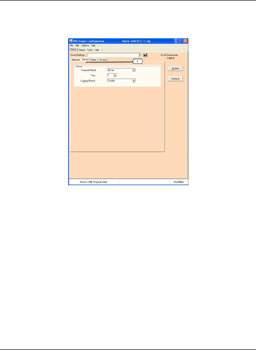
Configure Sensors for the Network Configure Battery-powered Sensors with the Sensor Configuration Utility
Primex Wireless, Inc. SNS™ Temperature and Humidity Sensors Installation Guide 42
Configuring Sensor Parameters
1. Select the Sensor tab (4), as shown in Figure 20.
Figure 20: SNS Battery Sensor Configuration Utility Sensor Settings
Enter the parameters for the Sensor tab. The settings are described in
2. Table 12.
3. Click the Alarm tab, shown in Figure 21. The fields in the Alarm tab are specific to the type
of sensor device you are configuring.
4. How you use the Alarm tab depends on whether you are setting alarms in the sensor device
or on the AMP. See Features of SNS Battery-powered Sensor Devices on page 18 for
suggestions about when to configure alarms directly in the sensor.
• To set alarms on the AMP, clear all data and remove checks from any boxes in the
Alarm tab. With no alarms set in the Alarms tab, when the sensor reports readings to
the AMP, the AMP will send notification if the readings are out of range.
• To set alarms in the sensor device, enter settings in the Alarm tab. Settings are
described in Table 13.
Note: Any alarms programmed directly in the sensor can only be removed or modified
by reprogramming the sensor.
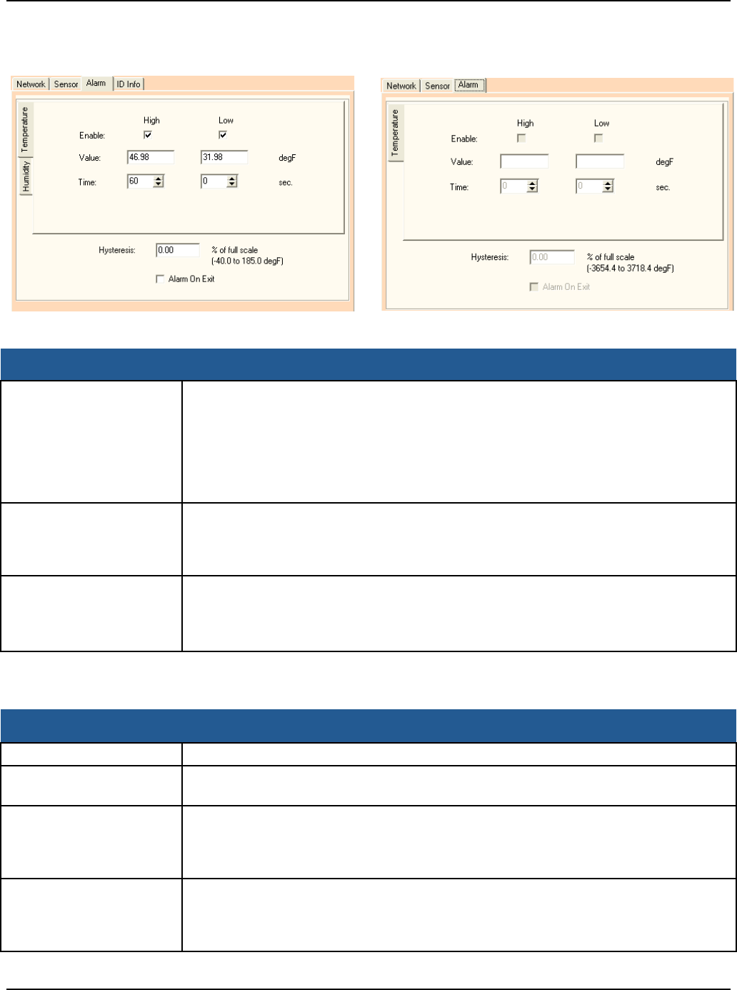
Configure Sensors for the Network Configure Battery-powered Sensors with the Sensor Configuration Utility
Primex Wireless, Inc. SNS™ Temperature and Humidity Sensors Installation Guide 43
Figure 21: SNS Battery Sensor Configuration Utility Alarm Tab for a Temperature Humidity Sensor and for a Single
Probe Temperature Sensor
Table 12: SNS Battery Sensor Configuration Utility Sensor Tab Fields and Values
Item Description
Transmit Period Select the desired Transmit Period of the sensor. This defines how often the sensor
uploads readings to the AMP. At the end of the transmit period, the sensor uploads
the readings regardless of whether they have changed. The Transmit Period you
select depends upon how you are using the temperature and humidity sensors.
Generally, 1 hour is sufficient. The shorter the selected time, the shorter the life of
the battery will be. To find out how long the battery will last at the selected Transmit
Period, view the Est. Expired field in the Status page.
Tries The number of transmission attempts for the given Transmit Period. If the sensor
receives an acknowledgement for the try, the sensor will stop transmitting; otherwise
the sensor will continue to transmit every 30 seconds until the number of attempts is
exhausted. The recommended number of tries is 3.
Logging Period This is the frequency with which the sensor will log readings in its log buffer. If the
Logging Period is shorter than the Transmit Period, the sensor will upload multiple
readings during each transmission.
Note: This field is for future use and is currently disabled.
Table 13: SNS Battery Sensor Configuration Utility Alarm Tab Fields and Values (All Sensor Device Types)
Item Description
Enable Enable either the High or Low alarms.
Value Enter value for either the High or Low threshold in the units shown, e.g. degrees
Fahrenheit or Relative Humidity.
Time Enter the number seconds the current value has to be above for the high alarm and
below for the low alarm before the alarm is triggered. This is the same as the Span
settings on the AMP and should not be less than the transmit period (reporting
interval).
Hysteresis Enter a value as a percentage of full scale that the current value must fall below the
high threshold or rise above the low threshold before the alarm is retriggered. Note:
This field is used only for alarms configured in the sensor and is not supported on the
AMP.
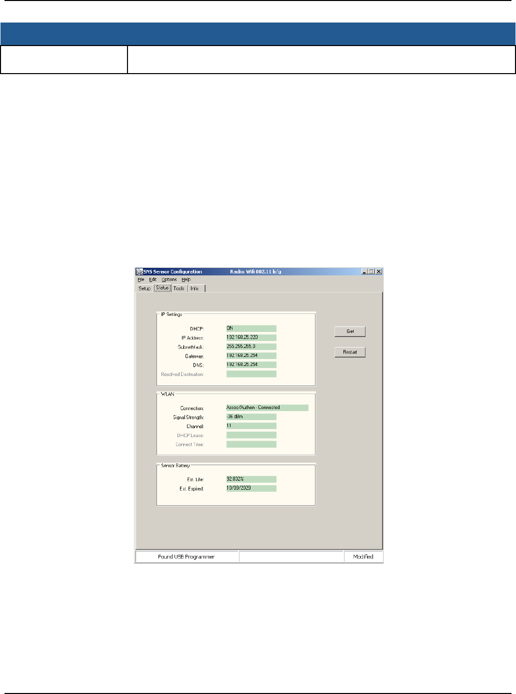
Configure Sensors for the Network Configure Battery-powered Sensors with the Sensor Configuration Utility
Primex Wireless, Inc. SNS™ Temperature and Humidity Sensors Installation Guide 44
Item Description
Alarm On Exit Check this box if it is desired to trigger an alarm when the value falls below the high
threshold or rises above the low threshold after the alarm time has expired.
Saving and Verifying the Configuration
1. Enter a name for the saved settings in the Saved Settings field. Click the Save icon. This
will save your settings for this type of sensor.
2. Click the Update button. The utility will configure the sensor with the settings presented in
the Setup tab and reboot the sensor device. You will see a pop-up when configuration is
complete.
3. Go to the Status tab, as shown in Figure 22 and described in Table 14. The fields will
populate to confirm the network settings or click Get to get the latest status information. The
Connection field should show Assoc/Authen Connected and the Rcv IP Address. The signal
strength should be approximately -65dBm.
Figure 22: SNS Battery Sensor Configuration Utility Status Tab
4. Go to the Tools tab, as shown in Figure 23. Click Contact Destination Host. The result
should show “Success”.
5. (Optional) Use the Info tab, Figure 37, to obtain the sensor device MAC address.
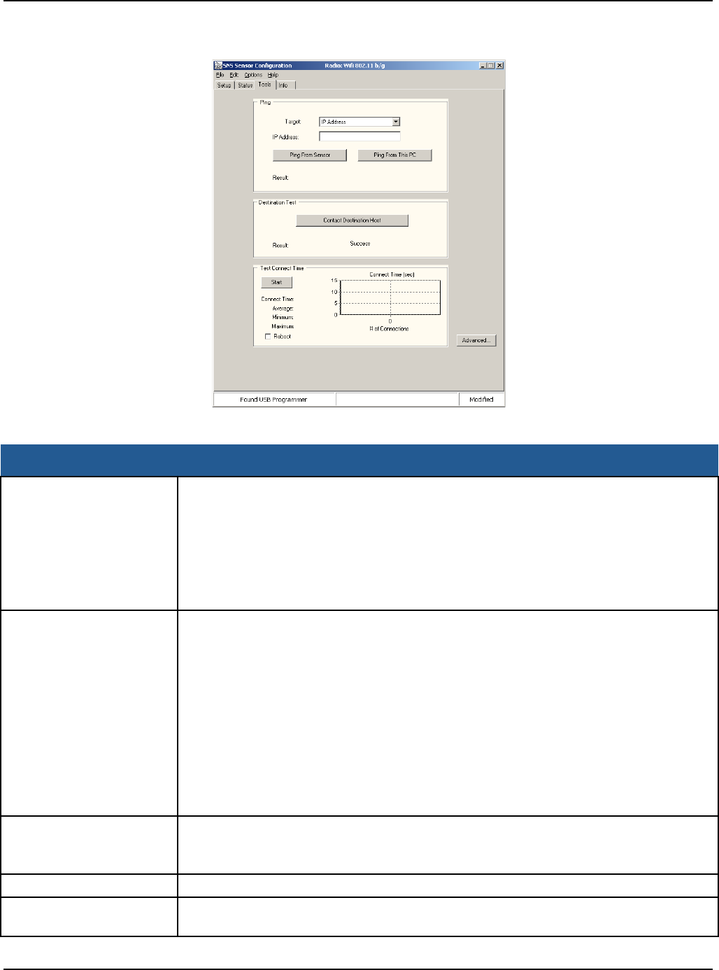
Configure Sensors for the Network Configure Battery-powered Sensors with the Sensor Configuration Utility
Primex Wireless, Inc. SNS™ Temperature and Humidity Sensors Installation Guide 45
Figure 23: SNS Battery Sensor Configuration Utility Tools Tab
Table 14: SNS Battery Sensor Configuration Utility Status Tab Fields and Values
Item Description
IP Settings DHCP: Off = static IP address information is being used; On = the IP settings have
been successfully assigned; Failed = the sensor could not obtain the IP settings.
IP Address: current IP address. If “0.0.0.0”, then no IP address has been assigned.
Subnet Mask: current assigned subnet mask.
Gateway: current assigned gateway address.
DNS: current assigned Name Server address.
Resolved Destination:
WLAN Connection: “Failed” = the sensor has failed to connect to a wireless network.
“Associated - not Connected” = the sensor has associated with the network but has
not connected. “Authenticated - not Connected” = security settings have been
authenticated but has not connected. “Assoc/Authen – Connected” = sensor has
associated and authenticated to the network and connected successfully to the
network.
Signal Strength: signal strength of the last communications. The signal strength can
vary from reading to reading. Multiple samples should be taken to determine the
signal strength.
Channel: This is the channel found during the Channel Auto Find feature or the
channel set in the Setup page. If the sensor cannot find a channel when in Auto Find
mode, the utility will display “none”.
Sensor Battery Est. Life: Estimated percentage remaining of the battery.
Est. Expired: Estimated date when the battery should be changed. (Dependant on
the Transmit Period and the number of alarms)
Get button Re-acquires the status information.
Restart button Causes the sensor to reboot, reconnect to the network and re-acquire the status
information.

Configure Sensors for the Network Configure Battery-powered Sensors with the Sensor Configuration Utility
Primex Wireless, Inc. SNS™ Temperature and Humidity Sensors Installation Guide 46
Forcing the Sensor to Check in with the AMP
1. Disconnect the USB Programming cable from the sensor.
2. Force the sensor to check in with the AMP using the service button. For the location of the
service button, see Features of SNS Battery-powered Sensor Devices on page 18.
3. Log into the SNS AMP server as a user with the role of Sensor Admin. See the SNS
Temperature and Humidity Sensors User Guide for information on using the AMP Sensors
module.
4. Check the AMP Sensor Devices page to confirm that the sensor device has checked in.
Sensors that are checking in for the first time appear in the Sensor Devices list with the
serial number in brackets in the Name column.
5. Double-click on the sensor device in the Sensor Devices list to view and edit information for
the sensor. By default, the information for the sensor will be the information in the Default
Sensor Profile for that type of sensor.
Configuring Additional Battery-powered Sensors using Saved Settings
1. Turn on the sensor.
2. Plug the USB Programming cable into the computer. The computer may display a pop-up
message stating that new hardware has been found.
3. Start the SNS Sensor Configuration Utility.
4. Connect the USB Programming cable to the sensor.
5. In the SNS Sensor Configuration Utility, click the Retrieve button to identify the type of
sensor. This will connect the software with the sensor.
6. In the Setup tab, select the Network tab, as shown in Figure 19.
7. Use the Saved Settings drop-down box to select the configuration settings for the type of
sensor you are configuring.
8. Click Update.
9. Force the sensor to check in with the AMP as described above.

Primex Wireless, Inc. SNS™ Temperature and Humidity Sensors Installation Guide 47
Install SNS Sensor Devices and Accessories
Once sensor devices are configured, they are ready for installation in their permanent locations.
Although not required, installing a thermobuffer with external probe sensor devices helps ensure
that sensor readings more closely approximate the temperature of the assets you are monitoring.
Install SNS Temperature and Humidity Sensors
Specifics of the installation depend on the monitored unit.
Installing Sensor Devices
1. For sensor devices with probes, in the monitored unit, locate an existing access hole, drill a
new access hole for insertion of the probe, or route the cable through the rubber door
gasket.
2. Route the external probe through the access hole.
3. (Optional) Install a thermobuffer. See Install a Thermobuffer on page 47.
4. Mount sensor and dress cable. All SNS AC-powered temperature and humidity sensor
devices come with self-adhesive hook-and-loop mounting tape. Alternatively, the sensor
device’s base plate has four holes that may be used to mount it with screws.
Note: The operating range of the AC-powered temperature sensor device is 32° -
95°F (0° - 35°C). If you’re monitoring temperatures in a freezer, the sensor
device must be mounted outside the freezer.
5. Ensure that sensor device is powered on.
6. Activate sensor using the Service button.
7. Log into the AMP and verify that sensor device has checked in and is reporting within
expected ranges.
Install a Thermobuffer
In many environments, normal daily use of refrigerators or freezers results in routinely opened
doors, occasionally for prolonged periods when restocking. This may cause air temperature to
change drastically and then recover just as quickly when the door closes. Temperature sensors
respond to this quick change and can give readings inconsistent with the actual temperature of
stored goods.
The Primex Wireless SNSGRP SNS Thermobuffer, shown in Figure 24, is used with SNS
temperature sensors to simulate the actual temperature of contents within coolers or freezers and
limit impact of fluctuating air temperature. This helps provide a higher degree of measurement
accuracy and reduces risk of potential material spoilage. When a thermobuffer is in use, fluctuations
are minimized so you can rely on the AMP threshold exceeded alerts and do not need to define
span exceeded alerts.
The thermobuffer features a plastic bottle that can be filled with food grade glycol to delay the
temperature spikes found during the replacement of materials or while servicing refrigerators,
freezers or walk-in coolers. Whether protecting vaccines, food, medications or other temperature
sensitive materials, the thermobuffer can help provide a more consistent measurement of your
investments.
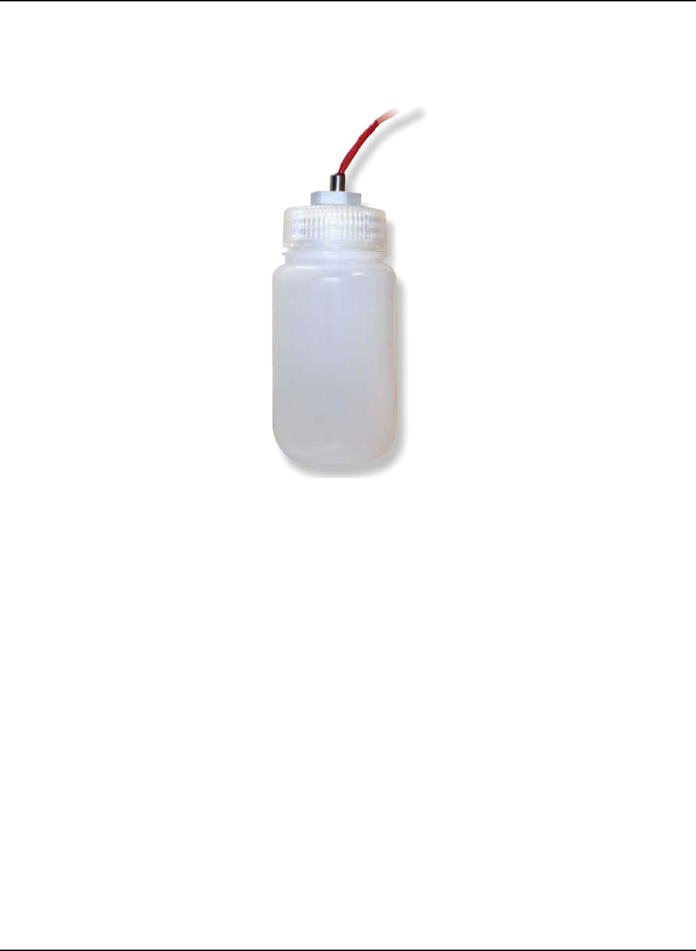
Install SNS Sensor Devices and Accessories Install a Thermobuffer
Primex Wireless, Inc. SNS™ Temperature and Humidity Sensors Installation Guide 48
Note: The thermobuffer is compatible with the ¼ in. thermistor probe and the standard 4
in. RTD probes.
Figure 24: SNS Thermobuffer
Installing a Thermobuffer
1. Fill the thermobuffer with food grade glycol, 3/4 - 7/8 full, allowing room for fluid expansion.
2. Insert the sensor probe through the grommet on the bottle cap with the tip of the probe fully
submersed in the glycol fluid.
3. Tighten the sensor grip with a wrench to secure the sensor in place.
4. Set the thermobuffer on a shelf, adhere it to a wall with hook-and loop mounting tape, or
attach it to a shelf with standard zip ties. Avoid placing the thermobuffer in direct contact
with the sides of the storage unit.

Primex Wireless, Inc. SNS™ Temperature and Humidity Sensors Installation Guide 49
Maintain Sensor Devices
SNS Temperature and Humidity Sensors require very little maintenance. This section contains the
following topic:
• Replace Batteries in Battery-powered Sensor Devices
Replace Batteries in Battery-powered Sensor Devices
Battery-powered sensors use two AA batteries. Batteries are located inside the sensor device
(Model SNS2TNS-2, Figure 4; Model SNS2TPH-2, Figure 12) or in an externally accessible battery
compartment (Model SNS2TPS-2, Figure 5). When replacing batteries, it is important to reset the
battery meter.
Resetting the Battery Meter
1. Turn off the sensor. Make sure the USB Programming Cable is disconnected from the sensor.
2. Engage the service button by either pressing the service button or using a magnet with some
sensors.
3. Turn the sensor on while the service button is engaged.
4. Wait four seconds.
5. Release the service button. The battery meter has been reset.
To confirm that the battery meter has been reset, reconnect the USB Programming Cable to the
sensor and view the estimated battery life in the battery sensor configuration utility Status tab. The
utility should indicate 100 %.
NOTE: When replacing the batteries in a dual battery SNS sensor always make sure you
replace both batteries together.

Primex Wireless, Inc. SNS™ Temperature and Humidity Sensors Installation Guide 50
Troubleshoot Sensors
This section contains the following topics:
• Troubleshooting AC-powered Sensors
• Troubleshooting Battery-powered Sensors
Troubleshooting AC-powered Sensors
Table 15 contains troubleshooting information for AC-powered sensors. Many of the
troubleshooting suggestions given below for battery-powered sensors apply to AC-powered sensors
as well.
Table 15: Troubleshooting AC-powered Sensors
Problem Resolution
Cannot access the AMP. Check wireless signal and network interface
(wired/wireless) using the browser-based configuration
tool. Refer to Appendix A: Browser-based
Configuration Tool on page 54.
No monitoring data on the AMP. Check wireless signal and network interface
(wired/wireless) using the browser-based configuration
tool. Refer to Appendix A: Browser-based
Configuration Tool on page 54.
Defective sensor
Troubleshooting Battery-powered Sensors
Overview
The SNS Sensor Configuration Utility can be used to help troubleshoot sensor issues with
connecting to a wireless network. The troubleshooting suggestions below assume you have the
SNS Sensor Configuration Utility installed on your computer and that you know how to use it.
When the programming cable is connected to the sensor, the sensor goes into “setup mode”. The
sensor continuously attempts to connect to the wireless network and will stay connected until the
programming cable is disconnected, or the sensor setup has changed.
The sensor is in “sensor mode” when the programming cable is not connected and the sensor
power switch is turned on. In “sensor mode”, the sensor remains in a low power state. When ready
to transmit, the sensor will turn on, connect, transmit a UDP packet, and then go back to the low
power state.
General Troubleshooting Suggestions
1. The sensor will not work reliably with signal strengths below about -65 dBm. If the signal
strength is smaller than that, the sensor may work marginally or not at all. Obviously the
better the signal strength, the better the chance the sensor has at delivering a sensor
packet.
2. The signal strength will vary from sample to sample. You should take multiple samples to
determine the signal strength. Signal strength is available in the Status tab and the Available
Networks window (press the “Find Networks” button in the Setup tab).

Troubleshoot Sensors Troubleshooting Battery-powered Sensors
Primex Wireless, Inc. SNS™ Temperature and Humidity Sensors Installation Guide 51
3. The red LED on the main sensor board indicates that a transmit attempt has just finished.
The green LED on the radio module indicates that radio module is connected to a network.
When in sensor mode, the green LED flashes when a connection is made. When in setup
mode (the programming cable is connected to the sensor), the green LED remains
continuously on when a connection is established. In setup mode the red LED never comes
on. In sensor mode the red LED flashes at the end of the transmit cycle.
4. In sensor mode, it can take up to 5 seconds for the transmit cycle to complete. This is from
when the service button is pressed to when the red LED is flashed.
5. If the connect time to the network is long (over 4 seconds), the sensor will not be able to
connect to the network. If you suspect the connect time to the network is long, use a PC to
connect to the network and then measure the connection that a PC takes to verify the
connection time.
6. Some access points will move between three channels (typically 1, 6 and 11). The SNS
Sensor will work with these access points with the Channel AutoFind feature but the
channels that are used must match the channels the sensor is configured for.
Troubleshooting Specific Symptoms
The list of symptoms includes:
• Cannot connect to the wireless network
• Can connect to the network but cannot obtain a dynamic IP address
• Can connect to the network but host is not receiving UDP packets
• Battery Meter indicates a lower battery life than expected
• SNS Sensor Configuration Utility cannot find the sensor
• SNS Sensor Configuration Utility Says Sensor is Off
• Loss of Data When Backup Power Fails
Cannot connect to the wireless network
1. Verify that the network exists.
2. Verify signal strength. Use the built in sensor signal strength meter. Use a signal strength
meter like a PC running “Network Stumbler”. Determine if adequate signal strength exists at
that location.
3. Verify network settings.
4. Make sure the network settings do not exclude 802.11b. Also make sure the router or
Access point accept connections of 1 Mega baud.
5. Turn off auto modes in the router or Access Point. The sensor does not support WPA2-PSK
TKIP. There are some routers and Access Points where the sensor will connect if the
network is set to WPA2-PSK AES and TKIP. Set the Access Point to WPA2-PSK AES.
6. If the sensor was previously connected at one location, but will not connect at the new
location, temporarily move the sensor to the previous location and verify operation. It is also
possible that a setting at the sensor or on the network has changed.
Can connect to the network but cannot obtain a dynamic IP address
1. Verify your network settings.
2. Verify that you are connected to the right network.

Troubleshoot Sensors Troubleshooting Battery-powered Sensors
Primex Wireless, Inc. SNS™ Temperature and Humidity Sensors Installation Guide 52
3. Use the “Ping From Sensor” function in the utility to ping an address that should be available
from the network (verify that the address is ping-able).
4. Use the “Ping From PC” function in the utility to see if your PC can ping an address on that
network (your PC must be connected to that network for this to work).
5. Use the “Ping From PC” function in the utility (if this PC is connected) to see if you can ping
the sensor when it is in setup mode. Go to the Status tab to determine the sensor’s IP
address.
6. Use a static IP address temporarily and connect to the network. Determine if sensor packets
are being received by the host.
7. Make sure the DHCP Server has not exhausted the number of assignable IP addresses.
8. It is possible the DHCP Server is taking too long to respond to the request.
Can connect to the network but host is not receiving UDP packets
1. Verify your network settings.
2. Verify that you are connected to the right network.
3. Verify that the Destination IP address is correct.
4. If using the broadcast address, verify that the network can support broadcasts. Most routers
by default will not route broadcast traffic.
5. If the host will respond to ping requests, use the “Ping From Sensor” function in the utility to
have the sensor ping the host. Use the “Ping From PC” feature if this PC is connected or a
PC on the network and ping the host. Also, try pinging the sensor when the sensor is in
setup mode.
6. Is the host ready to receive the sensor packets? Is the host configured to listen for the UDP
packets? Is the host software running? Is firewall software installed at the host that would
prevent the UDP traffic? Is there anything on the network that would restrict packets from
being routed (like MAC filtering)?
7. Use the “Contact Destination Host” function from the Tools tab.
8. If using a hostname for the destination address:
• Make sure the DNS address is correct (whether set as static or obtained through the
DHCP server).
• Is the hostname being resolved in setup mode? (Use the SNS Sensor, go to the Status
tab and examine the Resolved Destination field.)
AMP Battery Meter Icon Indicates a Lower Battery Life than Expected
Some possible causes of low battery life:
1. The transmission count was not reset when the batteries were last changed.
2. The transmit period is too short.
3. The service button was pressed a lot for this sensor.
4. There were many alarms for this sensor.
5. There were many tries for the sensor.

Troubleshoot Sensors Troubleshooting Battery-powered Sensors
Primex Wireless, Inc. SNS™ Temperature and Humidity Sensors Installation Guide 53
SNS Sensor Configuration Utility Cannot Find the Sensor
1. Make sure the programming cable is plugged into the sensor.
2. Does the red LED in the programming cable flash when doing an operation?
3. Disconnect the programming cable from sensor and connect again.
4. Disconnect the programming cable from sensor and then disconnect the cable from the PC.
Wait 30 seconds. Plug cable back into PC and into sensor.
5. Reboot your computer.
6. Use an externally powered USB Hub. Your computer may not be supplying enough power
through the USB port.
SNS Sensor Configuration Utility Says Sensor is Off
1. If the utility gives the following error “Sensor is possibly powered off!” disconnect the USB
Programming cable from the sensor, turn on the sensor, wait 5 seconds and connect the
USB Programming cable.
2. Be sure that you are turning the sensor on. See Features of SNS Battery-powered Sensor
Devices on page 18 for the location of the On/Off switch.
Long Connect Time
In some networks, one of the optional components of the connect time may take too long to perform
on a consistent basis. If the average connection time is too long, it is important to try isolating the
cause. To isolate the cause, try temporarily turning off one of the options and then re-measuring the
average connection time. For example, try setting the dynamically assigned IP address as the static
address temporarily, or try using a Destination IP address instead of the hostname address
temporarily.
Loss of Data When Backup Power Fails
All data being collected by the probes is stored in non-volatile memory. This data will be lost if
backup power fails. If AC power is restored before backup power fails and the temperature stayed
within the set limits, all of the readings will be sent to the AMP as a single check-in with the current
temperature for entire duration of the power outage. If a high or low limit is crossed while running on
backup power, the data is saved to EEPROM with a timestamp.
This data is erased in the event that backup power fails. If backup power does not fail, these
archived readings are sent to the AMP as well as current temperature readings when AC power is
restored. This provides a view of when temperatures went in and out of limits and for what duration.

Primex Wireless, Inc. SNS™ Temperature and Humidity Sensors Installation Guide 54
Appendix A: Browser-based Configuration Tool
All AC-powered sensors have a built-in web server that allows you to log into and configure the
device through a browser when attached directly to the computer via a network cable. With this
utility you can specify the address of the destination host and wired or wireless network parameters.
The utility also provides some tools for diagnosing problems. Opening the utility and using it to
configure AC-powered sensors are covered in Configure Sensors for the Network on page 25.
This section describes other actions that can be performed using the Browser-based Configuration
tool.
Action Buttons
These buttons act on the data entered on the browser-based Configuration Tool main window:
• Submit Configuration Button
• Micro Firmware Upload Button
• Radio Firmware Upload Button
• Site Survey Button
• Change Password Button
• Reset Device Config Button
• Exit Config Mode Button
• Test Configuration
Submit Configuration Button
Click the Submit Configuration button to accept your changes and store your settings in the
device’s onboard memory.
Micro Firmware Upload Button
Clicking the Micro Firmware Upload button displays the Micro Firmware Upload page. You use
this page to upload a new version of the firmware to the microcontroller. For more information on
updating sensor device firmware, refer to the SNS Temperature and Humidity Sensors User Guide.
Radio Firmware Upload Button
Clicking the Radio Firmware Upload button displays the Radio Firmware Upload page. You use
this page to upload a new version of the firmware to the 802.11 wireless radio. For more information
on updating sensor device firmware, refer to the SNS Temperature and Humidity Sensors User
Guide.
Site Survey Button
Clicking the Site Survey button displays the Site Survey page. You use this page to view a list of all
wireless access points recognized by your device.
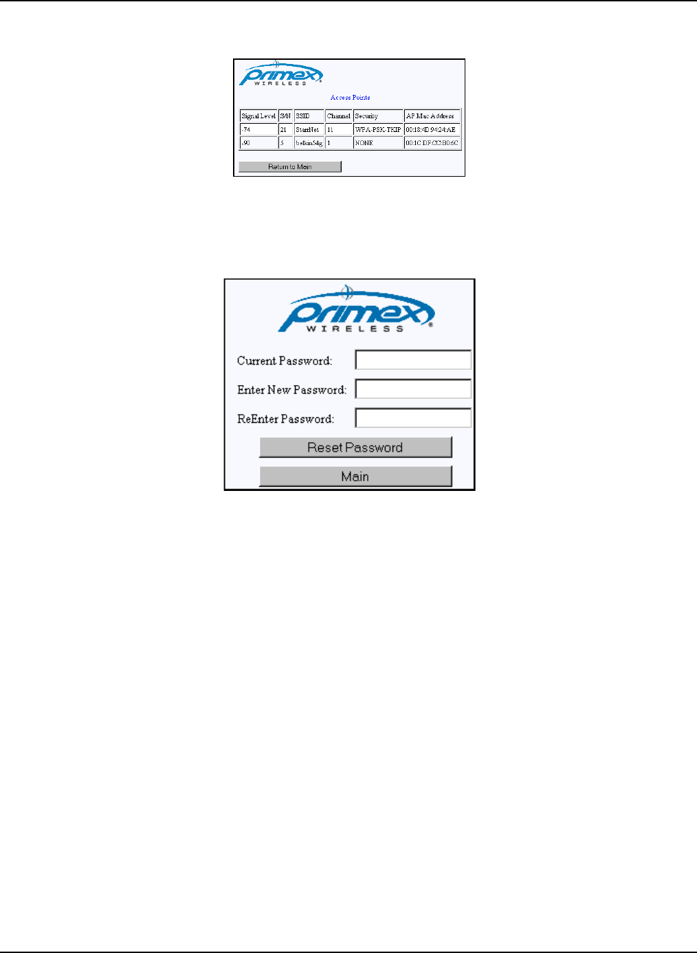
Appendix A: Browser-based Configuration Tool Action Buttons
Primex Wireless, Inc. SNS™ Temperature and Humidity Sensors Installation Guide 55
Figure 25: Site Survey Page
Change Password Button
Clicking the Change Password button displays the Change Password page. You use this page to
change the password used to log into this device.
Figure 26: Change Password Page
Changing the Device Login Password
Follow these steps to change your device’s login password.
1. Enter the current password in the Current Password field.
2. Enter the new password in the Enter New Password field.
3. Enter the new password in the Re-enter New Password field.
4. Click the Reset Password button.
Reset Device Config Button
Clicking the Reset Device Config button displays the Reset Device Config page. You use this page
to reset all device settings to their default state.
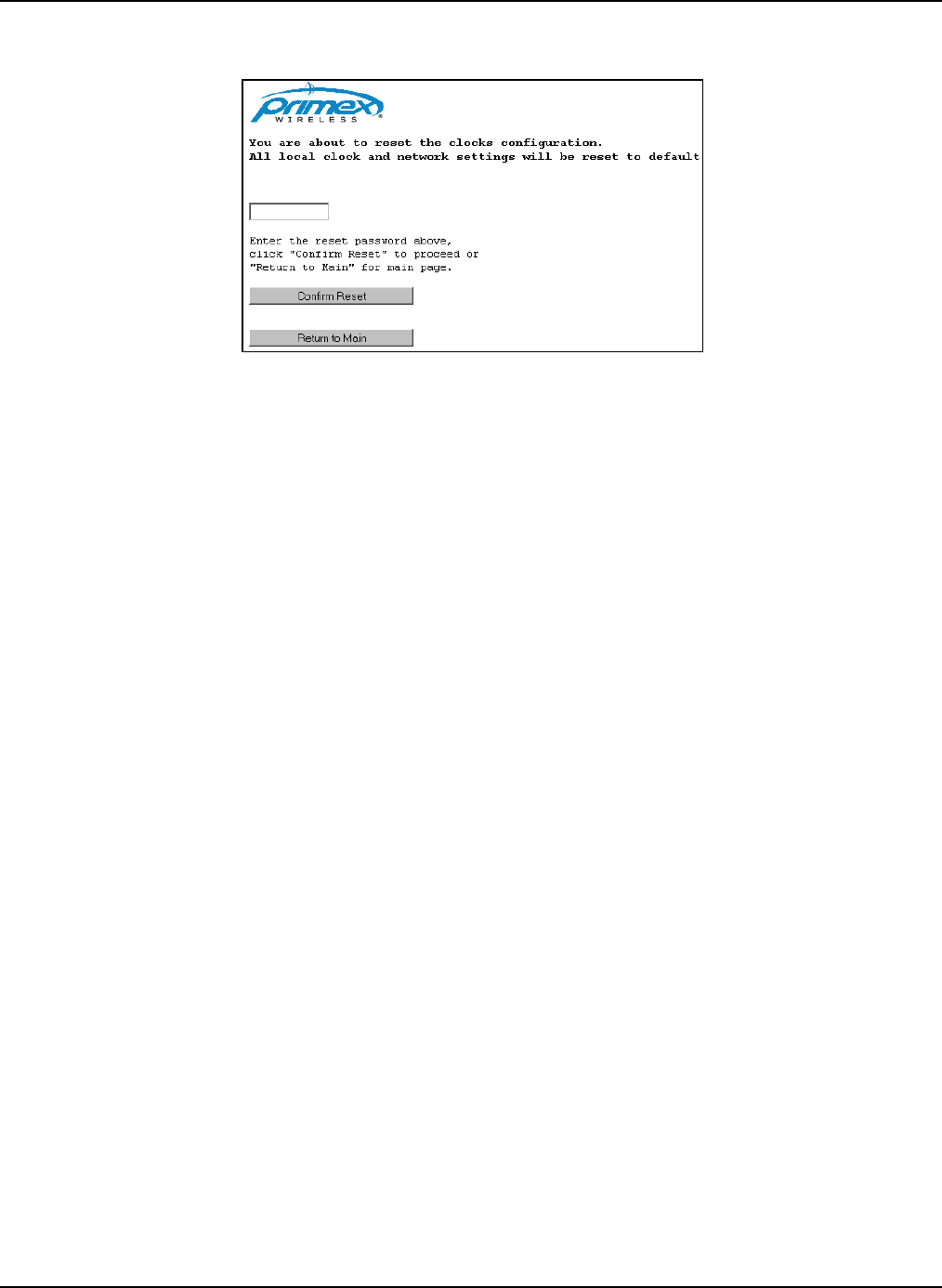
Appendix A: Browser-based Configuration Tool Action Buttons
Primex Wireless, Inc. SNS™ Temperature and Humidity Sensors Installation Guide 56
Figure 27: Reset Device Config Page
Resetting the Device Settings
Follow these steps to reset all device settings to their default state.
1. Enter the device password in the field.
2. Click the Confirm Reset button.
Test Configuration
Test Configuration forces the device to use the configured network settings and provides feedback
on each setting. When you click Test Configuration, the device will attempt to do the following:
• Make a wireless connection via the configured access point
• Get an IP from DHCP server on network
• Perform a UDP discovery of the configured AMP
Failure points along this path can better help with connection problems, separating those problems
related to incorrect/incomplete settings from those relating to network or access point issues.
Manage Logs
Manage Logs allows the collection and viewing of device logs. Manage Logs can be used in
conjunction with Test Configuration to troubleshoot device configuration and network issues.
Manage Logs permits you to enable logging, view log files, and delete log files. With logs enabled,
four sets of logs are collected, one per connection attempt.
Exit Config Mode Button
Clicking the Exit Config Mode button displays the Exit Config Mode page. You use this page to exit
the device configuration mode.

Primex Wireless, Inc. SNS™ Temperature and Humidity Sensors Installation Guide 57
Appendix B: Battery Sensor Configuration Utility
The SNS Sensor Configuration Utility configures and reads the settings in the SNS battery-powered
sensors. The SNS sensors supported are Single Temperature, Dual Temperature, and
Temperature and Humidity. With this utility you can specify the address of the destination host, the
wireless network parameters, transmit period of the sensor, and alarm information. The utility also
provides some tools for diagnosing problems. Using the utility to configure battery-powered sensors
is covered in Configure Battery-powered Sensors with the Sensor Configuration Utility on page 39.
This section covers the following topics:
• Installing the Configuration Utility
• User Interface
Installing the Configuration Utility
Before beginning, review the system requirements.
• USB programming cable
• Windows XP, 2000, 2003, Vista, or 7
• A computer with a USB port
Installing the Primex Wireless SNS Sensor Configuration Utility
1. Install the program on your computer by double-clicking on the provided install file Setup.exe,
whose icon looks like Figure 28.
Figure 28: Install Icon for the Battery Sensor Configuration Utility
2. Wait for the Welcome to the InstallShield window to appear.
3. On the Welcome to the InstallShield window, click Next to continue. The next window details
release information for the Primex Wireless SNS Sensor Configuration.
4. Read through this release information, and click Next to continue. The Customer Information
window opens.
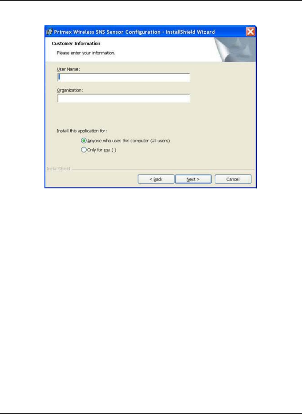
Appendix B: Battery Sensor Configuration Utility Installing the Configuration Utility
Primex Wireless, Inc. SNS™ Temperature and Humidity Sensors Installation Guide 58
Figure 29: Customer Information Window
5. Enter your username and organization in the appropriate boxes (optional) and choose if the
utility will be accessed by any user, or just the current user.
6. Click Next to continue. The Destination Folder window appears, identifying the installation path
where the Primex Wireless SNS Sensor Configuration files will be stored.
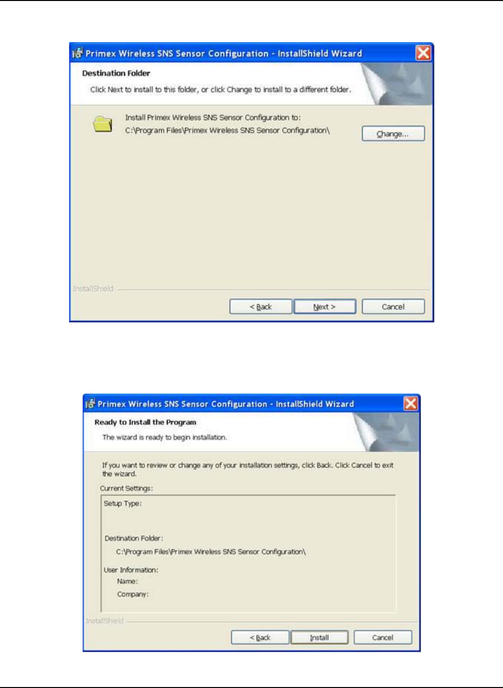
Appendix B: Battery Sensor Configuration Utility Installing the Configuration Utility
Primex Wireless, Inc. SNS™ Temperature and Humidity Sensors Installation Guide 59
Figure 30: Destination Folder Window
7. If you need to change the install path, click Change and follow the directions to search for
and/or type in a new path. When finished, click Next. The Ready to Install the Program window
appears.
Figure 31: Ready to Install the Program Window
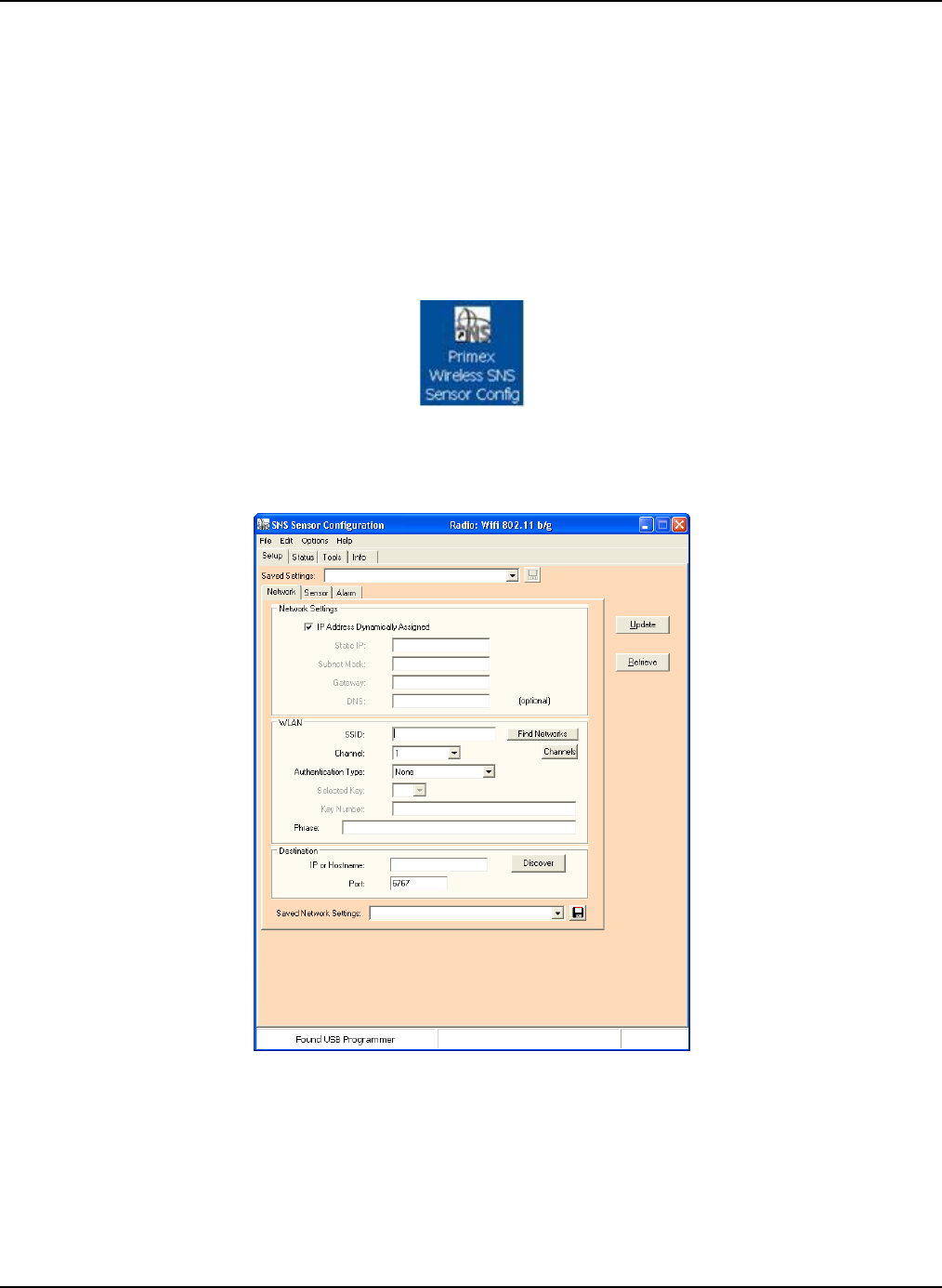
Appendix B: Battery Sensor Configuration Utility User Interface
Primex Wireless, Inc. SNS™ Temperature and Humidity Sensors Installation Guide 60
8. Review the information, and click Install to start the installation.
9. Click Finish when the completion window appears.
First Time Running after Install
Note Be sure to install the software before plugging the USB programmer into the USB
port of your computer.
1. After installing the software, insert the USB Programmer into the USB port of your computer.
2. Start the software by double clicking on the following icon on the desktop.
Figure 32: USB Port Icon for Sensor Configuration
The Sensor Configuration window opens, and the left frame of the status bar (the very lower
left of the program window) should say “Found USB Programmer” as shown in Figure 33.
Figure 33: Sensor Configuration Window after Installation
User Interface
The SNS Sensor Configuration has four main tabs: Setup, Status, Tools, and Info. The Setup tab
contains subtabs for configuring the sensor for the network and reporting parameters. For more on
the Setup tab, see Configure Battery-powered Sensors with the Sensor Configuration Utility on
page 39. When selecting the Status and Info tabs, the utility automatically extracts the information
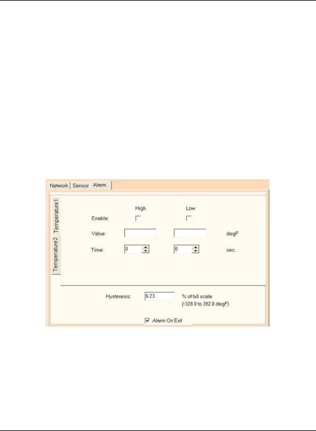
Appendix B: Battery Sensor Configuration Utility User Interface
Primex Wireless, Inc. SNS™ Temperature and Humidity Sensors Installation Guide 61
from the sensor when the windows are entered. With the Setup and Tools tabs, the interaction with
the sensor is initiated by the user.
Note: The configuration tabs/pages may look different depending on the type of sensor
connected.
Alarm Tab
In addition to receiving sensor alerts on the AMP, you can program some battery-powered sensors
with alarms by connecting the USB programming cable to the sensor. If the sensor has alarms
programmed and an alarm occurs, the sensor LED flashes as described in Features of SNS
Battery-powered Sensor Devices on page 18.
Alarms programmed in sensors cannot be modified from the AMP. Any alarms programmed directly
in the sensor can only be removed or modified by reprogramming the sensor.
You use the SNS Battery-powered Sensor Configuration Utility Alarm tab to program alarms in
battery-powered sensors. The utility will display the Alarm Tab window if the sensor supports
alarms. If the sensor has more than one I/O point that supports the alarm function, then the utility
displays the alarms settings in individual tab windows. A name will be given for the I/O point, for
example, Temperature 1, and displayed on the tab at the side of the window for each I/O point
Figure 34: Alarm Tab for Dual Temperature Sensor
The settings for dual temperature sensor are similar to the single temperature sensor. The
difference is that there are two separate probes to set alarms for, Temperature 1 and Temperature
2. Set thresholds as desired.
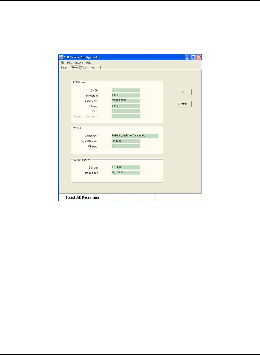
Appendix B: Battery Sensor Configuration Utility User Interface
Primex Wireless, Inc. SNS™ Temperature and Humidity Sensors Installation Guide 62
Status Tab
The Status tab, Figure 35, shows the current state of the IP settings, connection status, signal
strength, and battery life parameters. Fields in the Status tab are described in Table 14: SNS
Battery Sensor Configuration Utility Status Tab Fields and Values on page 45.
Figure 35: Status Tab
Tools Tab
The Tools tab, shown in Figure 36 and described in Table 16, has several methods for testing the
sensor connection.
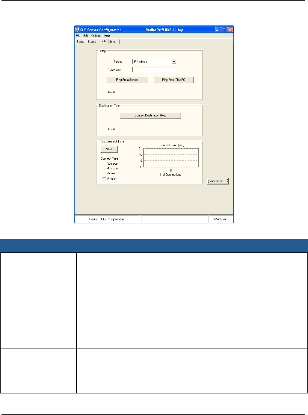
Appendix B: Battery Sensor Configuration Utility User Interface
Primex Wireless, Inc. SNS™ Temperature and Humidity Sensors Installation Guide 63
Figure 36: Tools Tab
Table 16: Tools Tab Fields and Values
Item Description
Ping Target: Select whether to ping the destination (AMP), gateway, or other address
specified in the IP Address field.
IP Address: Address of the entity specified in the Target drop-down.
Ping from Sensor: When the Ping button is pressed, the sensor uses either the IP
address in the IP Address field or the current address in the Destination IP field in
the Setup tab and pings that specified address. Once the ping operation is complete,
the utility indicates either failed or success, and specifies the IP address in the
Result field.
Ping from PC: When the Ping button is pressed, the sensor uses either the IP
address in the IP Address field or the current address in the Destination IP field in
the Setup tab and pings that specified address from the local PC. Once the ping
operation is complete, the utility indicates either failed or success, and specifies the
IP address in the Result field.
Destination Test The Utility will instruct the sensor to send a special packet to the Destination
Address. If the Destination responds with an acknowledgement, the Utility will
indicate success otherwise the Utility will display “Failed” in the Result field. Use the
Contact Destination Host function to confirm that the sensor is sending packets to
the Destination. Note: the Destination must be capable of responding with an
acknowledgement in order for this function to work.

Appendix B: Battery Sensor Configuration Utility User Interface
Primex Wireless, Inc. SNS™ Temperature and Humidity Sensors Installation Guide 64
Item Description
Test Connect Time The "Test Connect Time" function tests how well the sensor connects to the network.
Consistent connection performance is essential for longevity of sensor battery life.
This test will give an indication of how well the sensor connects to the network thus
giving an indication about battery life. If the average connection time is above 6
seconds, the sensor battery will be exhausted before the battery meter indicates.
Refer to Table 17 for the components of connect time.
Start Press the Start button to start the test. The utility will repeatedly attempt to connect
to the network with one second between connection attempts. The utility will show a
count of connection attempts, the last connect time, the average, minimum and
maximum connect times. The utility will show the history of connect attempts as a
bar graph. Each bar graph is the number of seconds for the attempt. The utility will
show a grey bar (at full scale) for failed connection attempts. Failed connection
attempts are not factored in the statistics.
Table 17 lists the components of the Connect Time.
Table 17: Tools Tab / Connect Time Components
Description Option 802.11 b (Seconds) 802.11 g (Seconds)
Cache/Noncache
Sensor Startup No 2
0.1
Auto Find Channel Yes 1
0.1
Associate / Authentication No <1
<1
DHCP Lookup Yes <1
<1
DNS Lookup Yes <1
<1
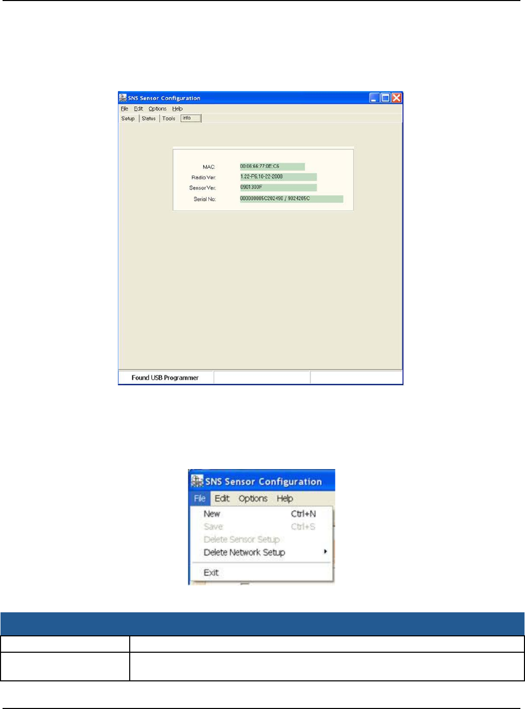
Appendix B: Battery Sensor Configuration Utility User Interface
Primex Wireless, Inc. SNS™ Temperature and Humidity Sensors Installation Guide 65
Info Tab
The Info tab, Figure 37, shows the MAC address, firmware version and the serial number of the
sensor.
Figure 37: Info Tab
Menu Options
File
Figure 38: File Menu Window
Table 18: File Menu
Item Description
New The SNS Sensor Configuration Utility clears the current settings.
Save SNS Sensor Configuration Utility saves the current settings to the name given in the
Saved Settings field.
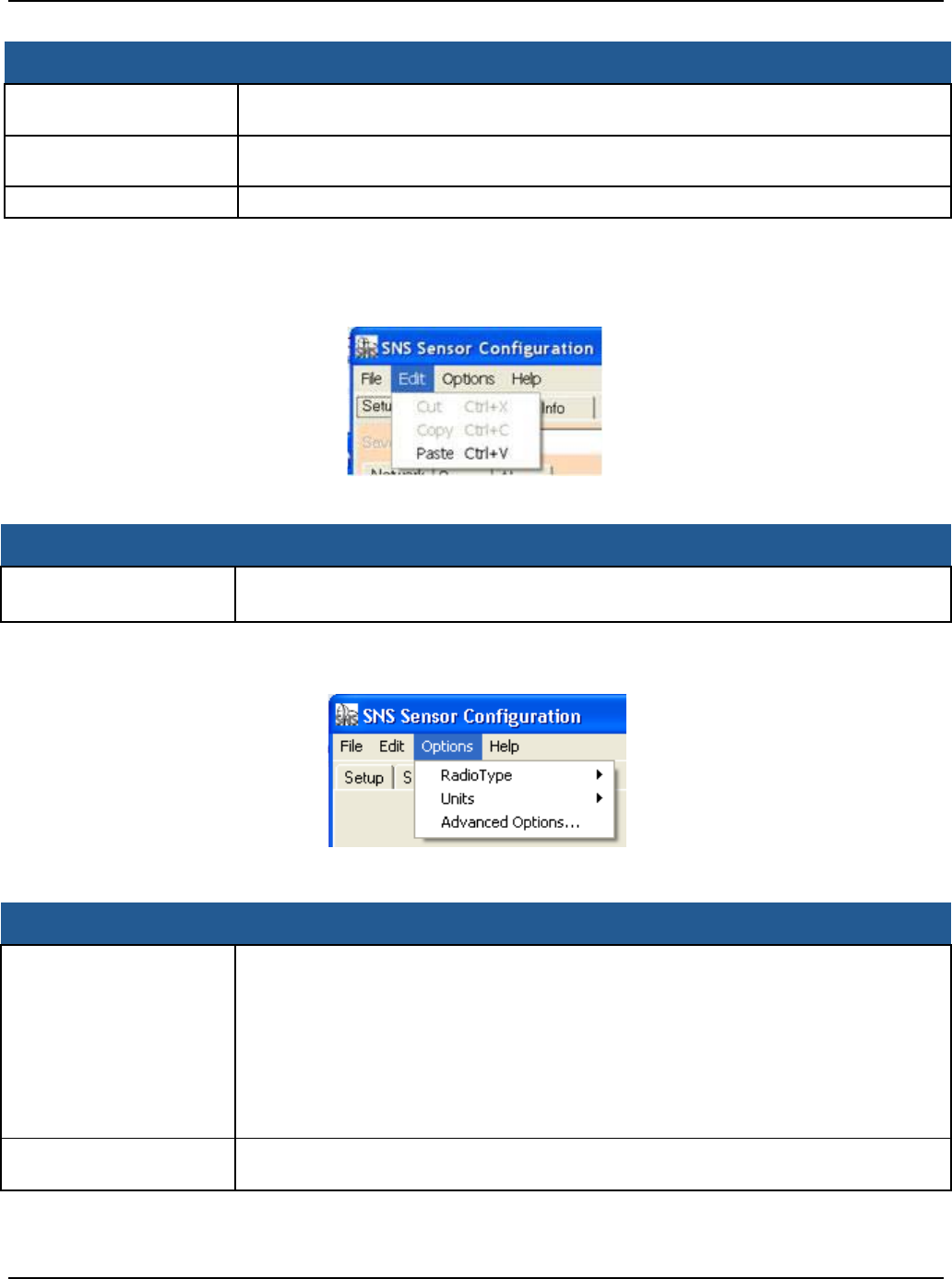
Appendix B: Battery Sensor Configuration Utility User Interface
Primex Wireless, Inc. SNS™ Temperature and Humidity Sensors Installation Guide 66
Item Description
Delete Sensor Setup SNS Sensor Configuration Utility presents a list of all the saved settings. You can
select which saved settings to delete.
Delete Network Setup SNS Sensor Configuration Utility presents a list of all the saved network settings.
You can select which saved network settings to delete.
Exit The SNS Sensor Configuration Utility closes the program.
Edit
Figure 39: Edit Menu Window
Table 19: Edit Menu
Item Description
Cut / Copy / Paste The SNS Sensor Configuration Utility provides the standard Windows
Cut/Copy/Paste to and from the clipboard.
Options
Table 20: Options Menu
Item Description
Radio Type None –Sensor has no radio. DO NOT USE FOR SNS BATTERY SENSORS.
Wifi 802.11b/g –Sensor has 802.11b or 802.11g radio
Digi XBee Zigbee–Sensor has a Digi XBee radio. DO NOT USE FOR SNS
BATTERY SENSORS.
Digi XBee 900/2.4--Sensor has a Digi XBee radio. DO NOT USE FOR SNS
BATTERY SENSORS.
Other –Sensor has a radio that is unknown or not defined yet in the utility. DO NOT
USE FOR SNS BATTERY SENSORS.
Units / Temperature Select the temperature to display the temperature alarm points (Celsius or
Fahrenheit).
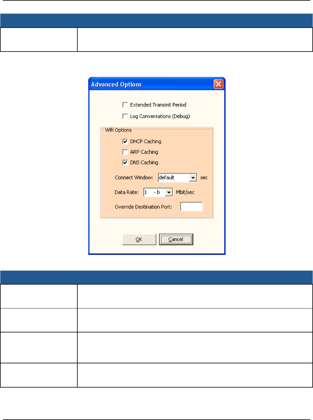
Appendix B: Battery Sensor Configuration Utility User Interface
Primex Wireless, Inc. SNS™ Temperature and Humidity Sensors Installation Guide 67
Item Description
Advanced Options Opens the Advanced Options window which contains parameters that are set every
time an Update operation is applied to the sensor. Advanced Options are described
in Table 21.
Advanced Options
Figure 40: Advanced Options Window
Table 21: Advanced Options Window
Item Description
Extended Transmit Period Adds 30 sec., 1 min., and 2 min. as additional options for the Transmit Period. These
additional periods are meant to be used for testing, evaluation and demonstration of
the sensor and can have a severe impact on the battery life of the sensor.
Log Conversations
(Debug) When this option is selected, the utility will capture the conversation between the
utility and the sensor and place it in a file called OutputLog.txt in the folder where
utility resides.
DHCP Caching When checked, the sensor will cache it’s IP address assigned from the DHCP server
until the DHCP lease time has expired or the sensor is power cycled. When
unchecked, the sensor will request an IP address every attempt to contact the host.
Default is unchecked.
ARP Caching When checked, the sensor will store and keep a list of IP/MAC relationships. When
unchecked, the sensor will rebuild the IP/MAC relationships every attempt to contact
the host.
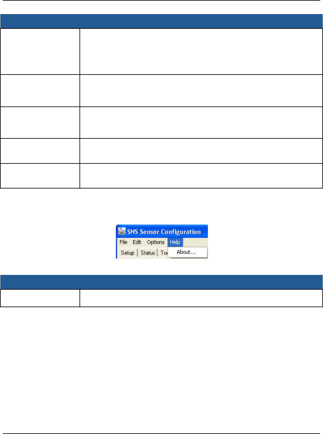
Appendix B: Battery Sensor Configuration Utility User Interface
Primex Wireless, Inc. SNS™ Temperature and Humidity Sensors Installation Guide 68
Item Description
DNS Caching When checked, the sensor will cache the IP address that results from the DNS
lookup of the Destination hostname. The sensor will keep the destination IP address
until either the DHCP lease time expires or the sensor is powered cycled. When
unchecked, the sensor will request a DNS lookup of the Destination hostname at
every attempt to contact the host. Set only if DNS caching and Dynamic IP are
enabled.
Connect Window The Connect Window is the amount of time in seconds that the sensor will attempt to
associate and authenticate to an access point or a wireless router (this includes the
time to obtain an IP address from a DHCP server). The default is 5 seconds and the
Connect Window can be set to 3 seconds to 8 seconds.
Data Rate The default data rate is 1 Mbit/sec and can be set from 1 to 54 Mbit/sec. The lower
the data rate the longer range the sensor will have. 1, 2, 5.5 and 11 are 802.11b data
rates. All other data rates are 802.11g data rates. Note: an access point or wireless
router may be configured to exclude 802.11b data rates.
Override Destination Port Leave blank to not use this feature. If a number (1 to 65535) is placed in this field,
the utility will force the Destination Port to be this entered number. Use this feature to
force the Destination Port be another value other than the default 6767.
Digi XBee 900 Radio
Address (Not shown in
Figure 40)
Set the Digi Xbee 900 radio address to a subset of the sensor serial number.
Help
Figure 41: Help Menu Window
Table 22: Help Menu
Item Description
About The SNS Sensor Configuration Utility presents a window that shows the version
number of the utility.
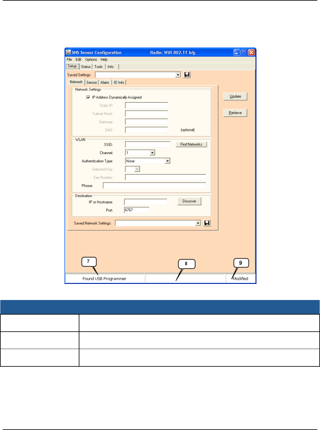
Appendix B: Battery Sensor Configuration Utility User Interface
Primex Wireless, Inc. SNS™ Temperature and Humidity Sensors Installation Guide 69
Status Bar
The status bar is located at the bottom of the utility window, and has a left, middle, and right panel.
Figure 42: Status Bar Window
Table 23: Status Bar Panels
Item Description
Left Panel (7) The utility shows the USB Programmer status in this panel: Found USB Programmer
or Looking for USB Programmer.
Middle Panel (8) The utility shows progress messages of the different actions: Update, Retrieve,
Status and Info.
Right Panel (9) The utility shows “Modified” message in this panel when the parameters in the Setup
page have been modified and need saving in order not to lose the parameters.

Appendix B: Battery Sensor Configuration Utility User Interface
Primex Wireless, Inc. SNS™ Temperature and Humidity Sensors Installation Guide 70
SNS_Sensor_Cfg.INI
The SNS Sensor Configuration Utility stores all its program information in an INI text file called
SNS_Sensor_Cfg.INI. Use a text editor to edit this file. Also restart the SNS Sensor Configuration
Utility if you make changes to the INI file. The following is description of the user changeable
parameters.
Override Maximum Number of Tries
MaxNumTries=5. Sets the maximum number of tries in the Sensor Tries field. (default max is 5)
Auto Find Channels
[Settings] ChannelMask=1,2,3,4,5,6,7,8,9,10,11 The ChannelMask parameter under the “Settings”
section defines the default channels that are used when a Setup gets created. Edit this parameter
to specify the channels for the sensor to search for. [template]
ChannelMask=1,2,3,4,5,6,7,8,9,10,11 The utility will use the ChannelMask parameter value in the
“Settings” channel to create the value in the template section. If you want to override the definition
for a particular setup, then edit this field.
Note: Do not set the Channel Auto Find search channels to more than 3 channels. This
will have an effect on sensor range and battery life.

Primex Wireless, Inc. SNS™ Temperature and Humidity Sensors Installation Guide 71
Appendix C: Regulatory Compliance
FCC Compliance
Pursuant to FCC 15.21 of the FCC rules, changes not expressly approved by Primex might cause
harmful interference and void the FCC authorization to operate this product.
FCC radio frequency interference
This equipment has been tested and found to comply with the limits for a Class B analog device,
pursuant to Part 15 of the FCC Rules. These limits are designed to provide reasonable protection
against harmful interference in a residential installation. This equipment generates, uses, and can
radiate radio frequency energy and, if not installed and used in accordance with the instructions,
may cause harmful interference to radio communications. However, there is no guarantee that
interference will not occur in a particular installation. If this equipment does cause harmful
interference to radio or television reception, which can be determined by turning the equipment off
and on, the user is encouraged to try to correct the interference by one or more of the following
measures:
• Reorient or relocate the receiver’s antenna.
• Increase the distance between the equipment and the receiver.
• Connect the equipment to an outlet on a circuit different from that to which the receiver is
connected.
• Consult the dealer or an experienced radio/TV technician for help.
FCC radiation exposure limits
The antennas used for this transmitter must be installed to provide a separation distance of at least
20 cm from all persons and must not be co-located or operating in conjunction with any other
antenna or transmitter. This is to comply with FCC RF exposure requirements in section 1.1307.