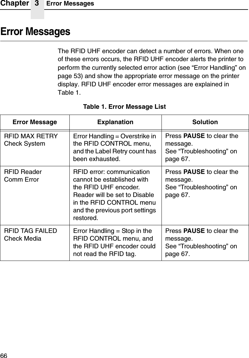
Printronix ADRFID RFID Enabled Thermal Printer User Manual PTX QSG T5000E RFID 177393A
Printronix Inc RFID Enabled Thermal Printer PTX QSG T5000E RFID 177393A
UserManual.wiki
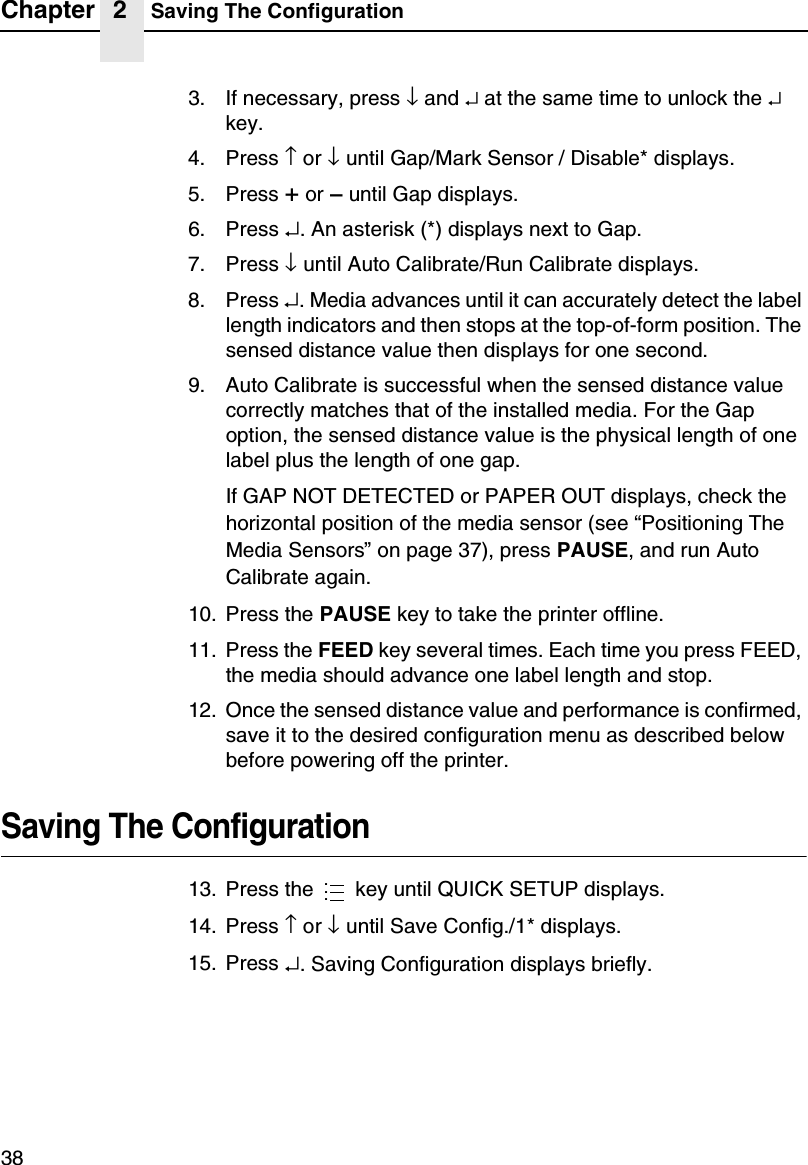
>
Printronix
>
ADRFID User Manual
User Manual
Navigation menu
Upload a User Manual
Namespaces
Wiki Guide
HTML
PDF
Info
Views
User Manual
Discussion / Help
Navigation


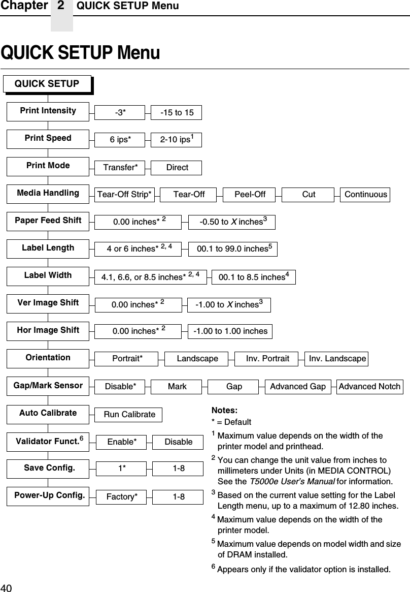
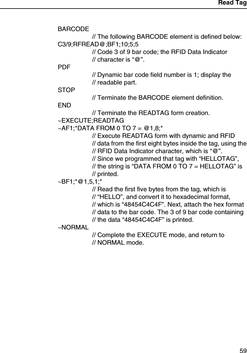
![QUICK SETUP Submenus41QUICK SETUP SubmenusPrint IntensitySpecifies the level of thermal energy from the printhead to be usedfor the type of media and ribbon installed.Large numbers imply more heat (thermal energy) to be applied foreach dot. This has a significant effect on print quality. The printintensity and speed must match the media and ribbon type toobtain the best possible print quality and barcode grades.The range is -15 through +15:•In Transfer mode, the default is -3.•In Direct Thermal mode, the default is 0.QUICK SETUP(cont. from previous page)SMT: StatusToolset [1]* Toolset [1] to Toolset [4]SMT: Sel ToolsetDisabled* EnabledEPC1zEPC2, 3SMT: Select ToolNotes:* = Default.1Appears only if Toolset [1] is selected underSMT: Sel Toolset.2Appears only if Toolset [2] is selected underSMT: Sel Toolset.3Undocumented options are reserved for internaluse and future design.UPCA1zUPCA2, 3 EAN81zEAN82, 3 EAN131zEAN132, 3 UCC1281zUCC1282, 3GTIN1zGTIN2, 3](https://usermanual.wiki/Printronix/ADRFID/User-Guide-373835-Page-41.png)


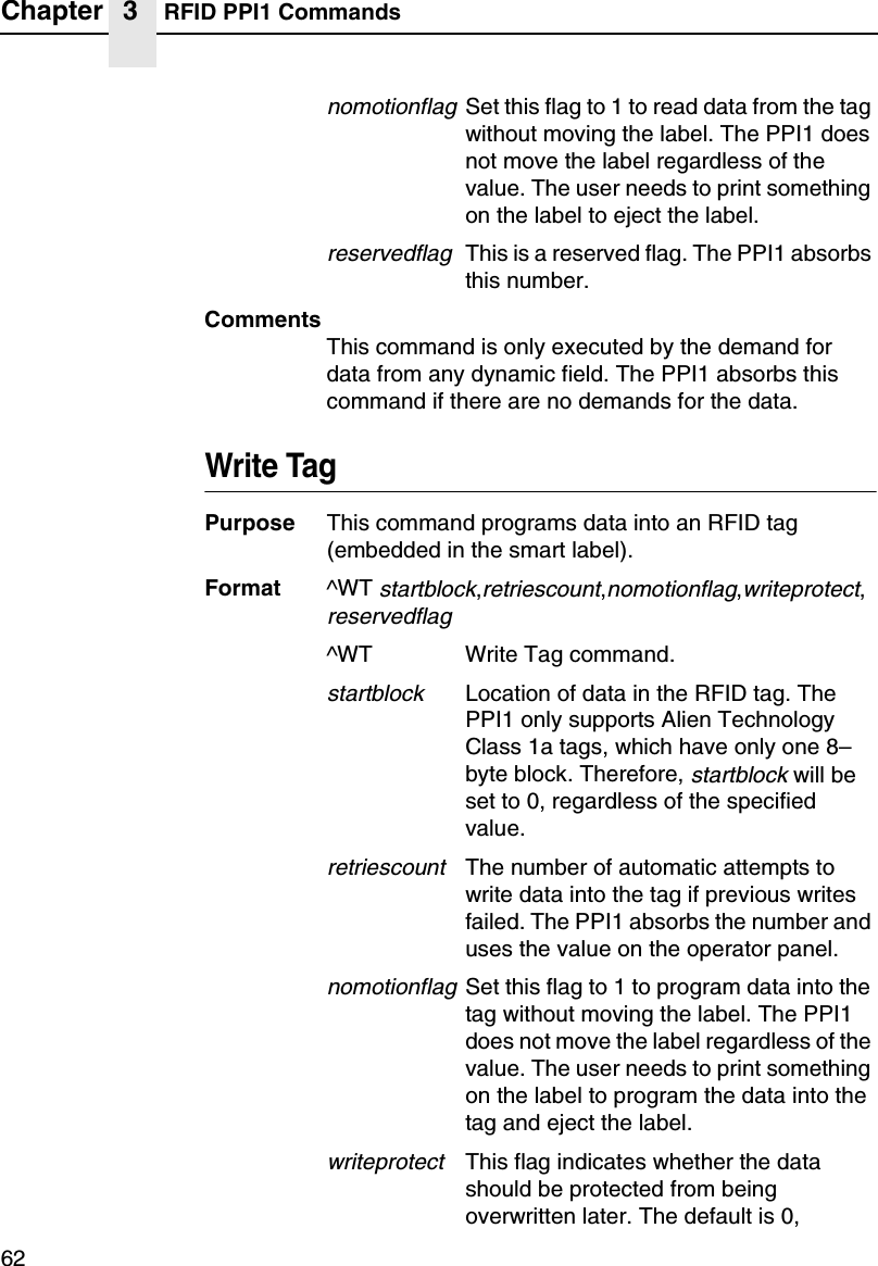
![Chapter 2 QUICK SETUP Menu48•Disabled.The printer will not command the validator to beginscanning and no errors will be reported. The counters will notbe incremented while the validator is disabled.NOTE: If you save a configuration with the validator enabled,power down and power up, and the validator is notconnected or not functioning, the error message “Validatornot communicating”will display briefly. The Validator menuwill not display.If the validator is installed, the default is Enable.Save Config.Allows you to save up to eight unique configurations to meetdifferent print job requirements. This eliminates the need to changethe parameter settings for each new job. The configurations arestored in memory and will not be lost if you turn off the printer. Thedefault is 1.Power-Up Config.You can specify one of the eight configurations as the power-upconfiguration. The default is Factory.SMT: StatusThis menu appears only if the RFID UHF encoder is installed. See“Software Migration Tools (SMT)”on page 63.•Disabled.The printer will disable the use of the SoftwareMigration Tools.•Enabled. The printer will enable the use of the SoftwareMigration Tools.SMT: Sel ToolsetThis menu appears only if the RFID UHF encoder is installed. See“Software Migration Tools (SMT)”on page 63.•Toolset [1].SMTsforPGL®emulation.•Toolset [2]. SMTs for PPI1 emulation.•Toolset [3] and Toolset [4]. Reserved for internal use andfuture design.](https://usermanual.wiki/Printronix/ADRFID/User-Guide-373835-Page-48.png)
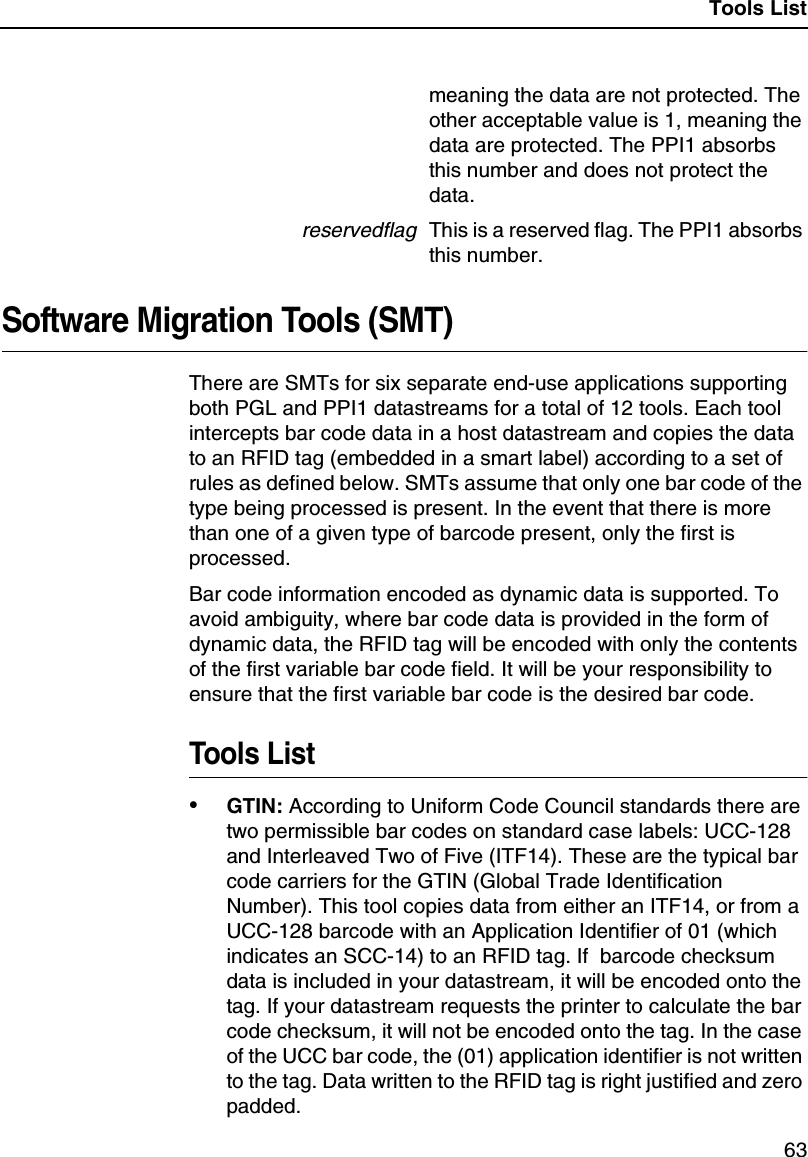
![QUICK SETUP Submenus49SMT: Select ToolThis menu appears only if the RFID UHF encoder is installed. See“Software Migration Tools (SMT)”on page 63.•EPC,GTIN,UPCA,EAN8,EAN13,andUCC128.SMTsdisplayed if Toolset [1] is selected under SMT: Sel Toolset.•zEPC,zGTIN,zUPCA,zEAN8,zEAN13, and zUCC128.SMTsdisplayed if Toolset [2] is selected under SMT: Sel Toolset.NOTE: Undocumented options are reserved for internal use andfuture design.For More InformationThis chapter has provided general information for use of yourprinter. The next chapter provides information about the RFID UHFencoder.Please refer to yourUser’s Manualfor more detailed informationincluding:•Other Configuration Menus•Interfaces•Diagnostics and Troubleshooting•Printer Options•Specifications•Glossary of Terms](https://usermanual.wiki/Printronix/ADRFID/User-Guide-373835-Page-49.png)


![Write Tag55RFID PGL CommandsWrite TagPurpose To program non-incremental data into an RFID tag(embedded in the smart label).MODE CREATEFormatRFWRITE;[HEX;][EPCm;][RFn;L;][LOCK;]ATp;[(D)datafield(D)]RFWRITE; The RFID Write Tag command.HEX; Optional parameter to indicate that thetext indatafieldis in hexadecimal formatand that it will be converted to binaryformat.EPCm; Optional parameter to indicate that thedata indatafieldshould be converted toan EPC number. When this parameter isused, the HEX option is automaticallyenabled and the data field is limited to amaximum of 14 digits. The AT parameteris ignored. The tag is then programmedas follows:Bits 0 to 1 are programmed with theEPC value 0 to 3, specified inm.Bits 2 to 57 are programmed with thehexadecimal characters in the data field(14 maximum). If the data field has lessthan 14 hexadecimal characters, zerosare assumed for the remaining digits.Bits 58 to 63 are set to zero.RFn;L; Optional parameter to indicate that thisfield has dynamic data. Replacenwith anumber ranging from 1 to 512 to identifythe field number of this RFWRITE field.ReplaceLwith the length of the dynamicdata string. If this option is used, the](https://usermanual.wiki/Printronix/ADRFID/User-Guide-373835-Page-55.png)


![Chapter 3 RFID PGL Commands58Read TagRead Tag is not a command, but an element of the ALPHA andBARCODE commands. See “Alphanumerics”and “Bar Codes”intheIGP/PGL Programmer’s Reference Manualfor moreinformation.Purpose Embed RFID data into an ALPHA or BARCODE datafield.Format <RDI>position,length[,format];<RDI> The RFID Data Indicator character, asdefined by the RFREAD parameter in theALPHA or BARCODE commands. Seethe ALPHA and/or BARCODE commanddescription for details.positionThe decimal number that specifies thestarting position of the data inside thetransponder.lengthThe decimal number that specifies thelength of the data to be read.formatReplace the optionalformatparameterwith any non-zero number to convert thedata to hexadecimal format.ExampleWrite tag contents, then read and insert the tag contents into anALPHA field.~CREATE;READTAG// Create the READTAG form.RFWRITE;AT1;*HELLOTAG*// Program the string “HELLOTAG”into the tagALPHA// The following ALPHA element is defined below:RFREAD@;AF1;27;3;5;0;0// RFID Data Indicator character is “@”.// Dynamic field number of this ALPHA element is 1.STOP// Terminate the ALPHA element definition.](https://usermanual.wiki/Printronix/ADRFID/User-Guide-373835-Page-58.png)


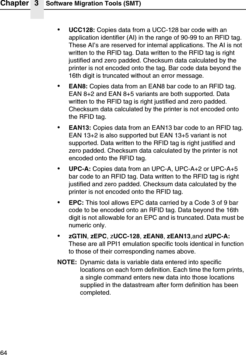
![Selecting The Tools65Selecting The Tools1. Press until QUICK SETUP displays.2. If necessary, press ↓and ↵at the same time to unlock the ↵key.3. Press ↓until SMT: Sel Toolset displays.4. Press ↓until Toolset [1] (PGL emulation) or Toolset [2] (PPI1emulation) displays.5. Press ↵to select it.6. Press ↓until SMT: Select Tool displays.7. Press ↓until the desired tool displays.8. Press ↵to select it.9. Press ↓and ↵at the same time to lock the ↵key, then pressPAUSE to take the printer offline.10. Press PAUSE again to put the printer online....](https://usermanual.wiki/Printronix/ADRFID/User-Guide-373835-Page-65.png)