Printronix ADRFID RFID Enabled Thermal Printer User Manual PTX QSG T5000E RFID 177393A
Printronix Inc RFID Enabled Thermal Printer PTX QSG T5000E RFID 177393A
User Manual
Smart Label Developer’s
Quick Setup Guide
The Printronix T5000eseries of Label Printers

This Quick Setup Guide contains a
CD-ROM with the following materials:
•RFID reference material and industry
primers
•The User’s Manual
•Programmer’s Reference Manuals
•Useful utility programs
The CD-ROM is located in a plastic
pocket in the back cover.
Donotdiscardthisguide.Ifyoumove
or pack the printer in the future, you will
need to follow the instructions in this
guide.
NOTICE

177393-001A
The Printronix T5000eseries of Thermal Printers
Smart Label Developer’s
Quick Setup Guide
Software License Agreement
CAREFULLY READ THE FOLLOWING TERMS AND CONDITIONS BEFORE USING THIS PRINTER.
USING THIS PRINTER INDICATES YOUR ACCEPTANCE OF THESE TERMS AND CONDITIONS. IF YOU
DO NOT AGREE TO THESE TERMS AND CONDITIONS, PROMPTLY RETURN THE PRINTER AND ALL
ACCOMPANYING HARDWARE AND WRITTEN MATERIALS TO THE PLACE YOU OBTAINED THEM, AND
YOUR MONEY WILL BE REFUNDED.
Definitions.
“Software”shall mean the digitally encoded, machine-readable data and program. The term “Software
Product”includes the Software resident in the printer and its documentation. The Software Product is licensed
(not sold) to you, and Printronix, Inc. either owns or licenses from other vendors who own, all copyright, trade
secret, patent and other proprietary rights in the Software Product.
License.
1. Authorized Use. You agree to accept a non-exclusive license to use the Software resident in the printer
solely for your own customary business or personal purposes.
2. Restrictions.
a. To protect the proprietary rights of Printronix, Inc., you agree to maintain the Software Product and
other proprietary information concerning the typefaces in strict confidence.
b. You agree not to duplicate or copy the Software Product.
c. You shall not sublicense, sell, lease, or otherwise transfer all or any portion of the Software Product
separate from the printer, without the prior written consent of Printronix, Inc.
d. You may not modify or prepare derivative works of the Software Product.
e. You may not transmit the Software Product over a network, by telephone, or electronically using any
means; or reverse engineer, decompile or disassemble the Software.
f. You agree to keep confidential and use your best efforts to prevent and protect the contents of the
Software Product from unauthorized disclosure or use.
3. Transfer. You may transfer the Software Product with the printer, but only if the recipient agrees to accept
the terms and conditions of this Agreement. Your license is automatically terminated if you transfer the
Software Product and printer.
Limited Software Product Warranty
Printronix, Inc. warrants that for ninety (90) days after delivery, the Software will perform in accordance with
specifications published by Printronix, Inc. Printronix, Inc. does not warrant that the Software is free from all
bugs, errors and omissions.
Remedy
Your exclusive remedy and the sole liability of Printronix, Inc. in connection with the Software is replacement
of defective software with a copy of the same version and revision level.
Disclaimer of Warranties and Limitation of Remedies
1. THE PARTIES AGREE THAT ALL OTHER WARRANTIES, EXPRESS OR IMPLIED, INCLUDING
WARRANTIES OF FITNESS FOR A PARTICULAR PURPOSE AND MERCHANTABILITY ARE
EXCLUDED.
Printronix, Inc. does not warrant that the functions contained in the Software will meet your requirements
or that the operation of the Software will be uninterrupted or error free.
Printronix, Inc. reserves the right to make changes and/or improvements in the Software without notice at
any time.
2. IN NO EVENT WILL PRINTRONIX, INC. BE LIABLE FOR LOST PROFITS, LOST DATA, BUSINESS
INTERRUPTIONS, OR ANY OTHER DIRECT, INDIRECT, INCIDENTAL OR CONSEQUENTIAL
DAMAGES ARISING OUT OF THE USE OF OR INABILITY TO USE THIS PRODUCT, EVEN IF
PRINTRONIX, INC. HAS BEEN ADVISED OF THE POSSIBILITY OF SUCH DAMAGES, OR ANY
DAMAGES CAUSED BY THE ABUSE OR MANIPULATION OF THE SOFTWARE. SOME STATES DO
NOT ALLOW THE EXCLUSION OR LIMITATION OF LIABILITY FOR CONSEQUENTIAL OR
INCIDENTAL DAMAGES, SO THE ABOVE LIMITATION MAY NOT APPLY TO YOU.
3. Printronix, Inc. will not be liable for any loss or damage caused by delay in furnishing a Software Product
or any other performance under this Agreement.
4. Our entire liability and your exclusive remedies for our liability of any kind (including liability for
negligence except liability for personal injury caused solely by our negligence) for the Software Product
covered by this Agreement and all other performance or nonperformance by us under or related to this
Agreement are limited to the remedies specified by this Agreement.
5. California law governs this Agreement.
Termination of License Agreement
This License shall continue until terminated. This license may be terminated by agreement between you and
Printronix, Inc. or by Printronix, Inc. if you fail to comply with the terms of this License and such failure is not
corrected within thirty (30) days after notice. When this License is terminated, you shall return to the place you
obtained them, the printer and all copies of the Software and documentation.
U.S. Government Restricted Rights
Use, duplication or disclosure by the Government is subject to restrictions as set forth in the Rights in
Technical Data and Computer Software clause at FAR 242.227-7013, subdivision (b) (3) (ii) or subparagraph
(c) (1) (ii), as appropriate. Further use, duplication or disclosure is subject to restrictions applicable to
restricted rights software as set forth in FAR 52.227-19 (c) (2).
Acknowledgement of Terms and Conditions
YOU ACKNOWLEDGE THAT YOU HAVE READ THIS AGREEMENT, UNDERSTAND IT, AND AGREE TO
BE BOUND BY ITS TERMS AND CONDITIONS. NEITHER PARTY SHALL BE BOUND BY ANY
STATEMENT OR REPRESENTATION NOT CONTAINED IN THIS AGREEMENT. NO CHANGE IN THIS
AGREEMENT IS EFFECTIVE UNLESS WRITTEN AND SIGNED BY PROPERLY AUTHORIZED
REPRESENTATIVES OF EACH PARTY. BY USING THIS PRINTER, YOU AGREE TO ACCEPT THE
TERMS AND CONDITIONS OF THIS AGREEMENT.
Communication Notices
This equipment has been tested and found to comply with the limits for a Class A digital device, pursuant to
Part 15 of the FCC Rules. These limits are designed to provide reasonable protection against harmful
interference when the equipment is operated in a commercial environment. This equipment generates, uses,
and can radiate radio frequency energy and, if not installed and used in accordance with the instruction
manual, may cause harmful interference to radio communications. Operation of this equipment in a residential
area is likely to cause harmful interference in which case the user will be required to correct the interference at
his own expense.
Properly shielded and grounded cables and connectors must be used in order to meet FCC emission limits.
Printronix is not responsible for any radio or television interference caused by using other than recommended
cables and connectors or by any unauthorized changes or modifications to this equipment. Unauthorized
changes or modifications could void the user’s authority to operate the equipment.

This device complies with part 15 of the FCC Rules. Operation is subject to the following two conditions: (1)
this device may not cause harmful interference, and (2) this device must accept any interference received,
including interference that may cause undesired operation.
Any change or modification to this product voids the user’s authority to operate it per FCC Part 15 Subpart A
Section 15.21 regulations.
CAUTION: This product should be positioned so that personnel in the area for prolonged periods may safely
remain at least 23 cm (9 in) from the readers antenna surface in an uncontrolled environment. See FCC OET
Bulletin 56 “Hazards of radio frequency and electromagnetic fields”and Bulletin 65 “Human exposure to radio
frequency electromagnetic fields.”
This product contains an intentional radiator with the following parameters:
Operating Frequency: 902-928 MHz
Typical RF Power: 25-100 miliwatts
Maximum RF Power: 1 Watt under abnormal conditions
Canadian Department of Communications Compliance Statement: This Class A digital apparatus
complies with Canadian ICES-003.
Avis de conformite aux normes du ministere des Communcations du Canada: Cet appareil numerique
de la classe A est conform ánorme NMB-003 du Canada.
European Community (EC) Conformity Statement:
This product is in conformity with the protection requirements of EC Council Directive 89/336/EEC on the
approximation of the laws of the Member States relating to electromagnetic compatibility. Printronix cannot
accept responsibility for any failure to satisfy the protection requirements resulting from a non-recommended
modification of the product, including the fitting of non-Printronix option cards.
German Conformity Statement:
Zulassungsbescheinigung Gesetz über die elektromagnetische Verträglichkeit von Geraten (EMVG) vom 30.
August 1995
Dieses Gerät ist berechtigt in Übereinstimmung mit dem deutschen das EG-Konformitätszelchen - CE - zu
führen.
Der Außteller der Konformitätserklärung ist die Printronix......(1)
Informationen in Hinsicht EMVG Paragraph 3 Abs. (2) 2:
EN 55022 Klasse A Geräte bedürfen folgender Hinweise:
Nach dem EMVG: “Geräte dürfen an Orten, für die sie nicht asreichend entstört sind, nur mit besonderer
Genehmigung des Bundesminesters für Post und Telekommunikation oder des Bundesamtes für Post und
Telekommunikation betrieben werden. Die Genehmigung wird erteilt, wenn keine elektromagnetischen
Störungen zu erwarten sind.”(Auszug aus dem EMVG, Paragraph 3, Abs. 4) Dieses Genehmigungsverfahren
ist nach Paragraph 9 EMVG in Verbindung mit der entsprechenden Kostenverordnung (Amtsblatt 14/93)
kostenpflichtig.
Nach der EN 55022: “Dies ist eine Einrichtung der Klasse A. Diese Einrichtung kann im Wohnbereich
Funkstörungen verursachen; in diesem Fall kann vom Betreiber verlangt werden, angemessene Maßnahmen
durchzuführen und dafür aufzkommen.”
Anmerkung: Um die Einhaltung des EMVG sicherzustellen sind die Geräte, wie in den Handbüchern
angegeben, zu installieren und zu betreiben.
Das Geräterfüllt die Schutzanforderungen nach EN 55024 und
EN 55022 Klasse A.
This product has been tested and found to comply with the limits for Class A Information Technology
Equipment according to European Standard EN 55022. The limits for Class A equipment were derived for
commercial and industrial environments to provide reasonable protection against interference with licensed
communication equipment.
This is a Class A product. In a domestic environment
this product may cause radio interference in which
case the user may be required to take adequate
measures.
Warning
Printronix makes no representations or warranties of any kind regarding this material, including, but not limited
to, implied warranties of merchantability and fitness for a particular purpose. Printronix shall not be held
responsible for errors contained herein or any omissions from this material or for any damages, whether
direct, indirect, incidental or consequential, in connection with the furnishing, distribution, performance or use
of this material. The information in this manual is subject to change without notice.
This document contains proprietary information protected by copyright. No part of this document may be
reproduced, copied, translated or incorporated in any other material in any form or by any means, whether
manual, graphic, electronic, mechanical or otherwise, without the prior written consent of Printronix.
COPYRIGHT © 2003 PRINTRONIX, INC. All rights reserved.
Trademark Acknowledgements
Printronix and PGL are registered trademarks of Printronix, Inc.
Zebra and ZPL are trademarks of Zebra Technologies Corporation.

11
1 Smart Label Developer’s Application &
Reference Notes13
Overview..............................................................................13
What To Expect When Running Your RFID Application......14
Factors Affecting Smart Label Performance .................14
Overstruck Smart Labels...............................................15
Smart Label Limitations.................................................15
Transitioning From UCC/GTIN Applications Using Printronix
Software Migration Tools (SMT)..........................................16
How Printronix Makes It Easy .......................................16
How It Works.................................................................16
How To Order More Smart Labels.......................................17
Printronix Professional Services..........................................18
What We Can Do ..........................................................18
Contact Information.......................................................18
Hardware/Infrastructure Considerations..............................18
Useful Industry Web Links...................................................19
Reference Material........................................................19
2 Printer Setup ........................................... 21
Unpacking And Installing The Printer ..................................21
Unpacking The Printer ..................................................21
Removing The Internal Packing Material ......................22
Installation .....................................................................23
Controls And Indicators .......................................................24
Power Switch ................................................................24
Control Panel ................................................................25
Table of Contents

Table of Contents
12
Loading Media And Ribbon .................................................29
Loading Roll Media .......................................................29
Loading Ribbon.............................................................34
Printing Adjustments............................................................36
Printhead Pressure Adjustment ....................................36
Printhead Pressure Block Adjustments.........................36
Positioning The Media Sensors ....................................37
Running Auto Calibrate .......................................................37
Saving The Configuration ....................................................38
Run A Barcode Demo Test..................................................39
QUICK SETUP Menu ..........................................................40
QUICK SETUP Submenus............................................41
For More Information ...........................................................49
3 Smart Label Development....................... 51
Overview..............................................................................51
RFID CONTROL Menu........................................................52
RFID CONTROL Submenus.........................................53
Admin User Menu Items................................................54
RFID PGL Commands.........................................................55
Write Tag ......................................................................55
Read Tag ......................................................................58
RFID PPI1 Commands ........................................................60
Get Tag Unique ID ........................................................60
Set Tag Type ................................................................60
Read Tag ......................................................................61
Write Tag ......................................................................62
Software Migration Tools (SMT)..........................................63
Tools List.......................................................................63
Selecting The Tools ......................................................65
Error Messages ...................................................................66
Troubleshooting...................................................................67

13
1Smart Label Developer’s
Application &
Reference Notes
Overview
Congratulations on your purchase of the industry’s first Smart Label
Developer’s Kit. The intent of this kit is to provide a complete
environment for the printing and encoding of RFID smart labels
right out of the box. Printronix has specifically designed this kit to
help you fast track your RFID pilot through the use of a suite of
Software Migration Tools (SMT).
The Printronix Smart Label Developer’s Kit contains:
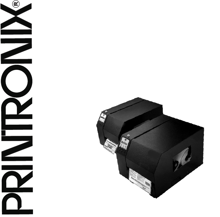
•T5000e thermal printer: a web-enabled, industrial-grade
thermal bar code printer designed for exacting label
applications
•Integrated RFID UHF encoder
CAUTION
Static electricity can damage the smart labels. Open the media
cover of the printer and touch an unpainted metal part of the
printer before you handle smart labels. This will discharge any
static electricity that may have been on your hands.
•Two rolls of 500 smart labels with Alien Technologies, Class 1,
915MHz inlays
•Software migration tools that permit the seamless encoding of
smart labels

Chapter 1 What To Expect When Running Your RFID Application
14
•One 450 m thermal premium wax ribbon
•Media starter kit (100 4 inch x 6 inch standard labels, 50 m
thermal premium wax ribbon, and a printhead cleaning pen)
•Programming manuals
•Smart Label Developer’s Quick Setup Guide (this manual)
•Application and reference notes (this chapter)
•Technical support
•Printronix’sPrintNet®Enterprise: a web-enabled remote
network print management system that provides instantaneous
visibility to every network printer and allows users to configure
simultaneously an unlimited number of Printronix printers. This
edition of PrintNet Enterprise also supports management of the
additional RFID UHF encoder capabilities.
We are proud to partner with you as you embark on your RFID
journey!
What To Expect When Running Your RFID
Application
Factors Affecting Smart Label Performance
Smart labels are based on an EEPROM technology that requires
some time to program. This minor pause between labels may be
noticed by the user. This time is necessary to better ensure
consistent quality and improved reliability.
When dealing with smart labels, it is possible that an occasional
RFID tag may require to be written and verified more than once
(retry) before being considered acceptable. In this event each retry
time will be added to the inter-label pause.

Overstruck Smart Labels
15
Overstruck Smart Labels
If an RFID tag within a smart label is deemed unacceptable after
execution of the defined number of internal retries, the following
actions are performed:
•If Error Handling is set to Overstrike (the default), the
unacceptable smart label will print with a grid Overstrike
pattern. If the Label Retry Count is greater than zero (the
default is 5), the next smart label will be tried until the label retry
count is exhausted.
•If Error Handling is set to Stop, the printer will stop, give an
error message, and discard the failing form data.
•If Error Handling is set to None, the printer will continue to the
next smart label with the next form and discard the failing form
data.
Smart Label Limitations
The smart labels currently supported have the following
characteristics:
•UHF 915MHz radio frequency identification tag inlay
•EPC class 1 tags –64 data bits Write Few / Read Many
•4 inch x 6 inch label stock
•Nominal roll size is 500 smart labels. An additional number of
smart labels may be added to the Printronix smart label rolls to
compensate for tags that are deemed unacceptable. This is so
you can have 500 “good”labels.
NOTE: It is highly recommended that additional smart labels are
purchased directly from Printronix to assure the highest
level of performance and reliability. See “How To Order
More Smart Labels”on page 17.

Chapter 1 Transitioning From UCC/GTIN Applications Using Printronix Soft-
16
Transitioning From UCC/GTIN Applications Using
Printronix Software Migration Tools (SMT)
It is more than likely that your software is already set up to create
barcodes. You may have also spent a lot of time creating
compliance label templates & integrating them into your system.
The Smart Label Developer’s Kit Software Migration Tools will
allow you to effortlessly transition from printing compliance labels to
smart labels.
How Printronix Makes It Easy
If you are printing bar codes now, you can print smart labels —no
change to your host data stream or existing compliance templates
is required.
How It Works
A set of Software Migration Tools has been created to intercept the
bar code data in a host datastream and copy the data to an smart
label’s RFID tag according to a set of rules. Each tool has been
designed for a specific end-use application. By simply selecting the
desired Software Migration Tool from the printer’s operator panel,
you automatically enable the printer to create an RFID smart label
from your existing software application even if it does not have the
functionality to program RFID tags. The tools include:
•GTIN: Copies the Global Trade Identification Number (GTIN)
bar code data for case and palette labels onto the smart label’s
RFID tag.
•EAN-8,EAN13,UPCA,andUCC128: These tools copy the
data from their respective bar code symbologies to a smart
label’s RFID tag. This enables the achievement of supply-chain
efficiencies with RFID-ready trading partners while at the same
timeremainingcompatiblewiththosewhoarenot.

How It Works
17
•EPC: This tool allows EPC data to be directly encoded into the
smart label’s RFID tag. Simply have your existing software
application write the desired EPC number to a Code 3 of 9
barcode. The printer will then write the EPC data to the RFID
tag without printing the bar code.
The existing toolset will meet the needs of many RFID early
adopters. If you have a requirement for a Software Migration Tool
not included in this kit, feel free to contact us.
To select and use the tools, see “Software Migration Tools (SMT)”
on page 63.
How To Order More Smart Labels
To order more RFID smart labels, contact Printronix:
1 (800) 733-1900
www.printronix.com
Part Number
Roll of 500 four inch by six inch EPC Class 1 smart labels:
204932-001
NOTE: Due to the dynamic state of the RFID market, the cost of
smart labels will fluctuate to market conditions. Please
check for the latest pricing. (Price breaks are available for
large orders.)

Chapter 1 Printronix Professional Services
18
Printronix Professional Services
What We Can Do
Printronix can partner with you on your RFID pilot project to make
your existing software applications RFID/smart label capable. We
specialize in AutoID Consulting, compliance labeling, third party
software integration, and label generation.
Contact Information
RFID Pilot Manager
Stephen Morris
714-368-2486
smorris@printronix.com
Hardware/Infrastructure Considerations
Once your smart labels have been applied to their target container
or pallet you will need external readers for tracking them through
your supply chain. Such readers are typically networked devices
that are deployed at key points in the warehouse or distribution
center to track incoming and outgoing packages. The readers are
managed through a server for gathering and filtering all the RFID
information. Readers may have multiple antennas to maximize read
range and reliability.
The readers you purchase must be compatible with the smart
labels programmed by the printer. Specifically, they should be EPC
Class I compliant. Fixed position readers and their antennas can be
purchased from Alien Technology (www.AlienTechnology.com).
Handheld readers with integrated antennas can be purchased from
AWID (www.awid.com).
The data that are gathered by the reader servers must be managed
for tracking and archiving purposes. Software applications that
perform these tasks are available from companies such as
Manhattan Associates (www.manh.com).

Reference Material
19
Useful Industry Web Links
Reference Material
Auto-ID Center
www.autoidcenter.org
Uniform Code Council
www.uc-council.com
EPC Global
www.uc-council.org/epcglobal/
RFID Journal
www.rfidjournal.com
For a general overview of RFID technology, please see the Alien
Technology RFID Primer located on the CD contained in this
manual. (This primer is currently unavailable at time of publication).
Alien Technology
www.alientechnology.com
Advanced Wireless Indentifications
www.awid.com

Chapter 1 Useful Industry Web Links
20

21
2Printer Setup
Unpacking And Installing The Printer
Unpacking The Printer
The printer is shipped in a carton and protective bag. Keep all
packing material in case shipping is required.
CAUTION
Avoid touching the electrical connectors to prevent
electrostatic discharge damage while setting up the printer.
The discharge of accumulated electrostatic energy can
damage or destroy the printhead or electronic components
used in this device.
CAUTION
Do not place the printer on its backside during unpacking or
handling, because damage to the printer interface connector
may occur.
Chapter 2 Unpacking And Installing The Printer
22
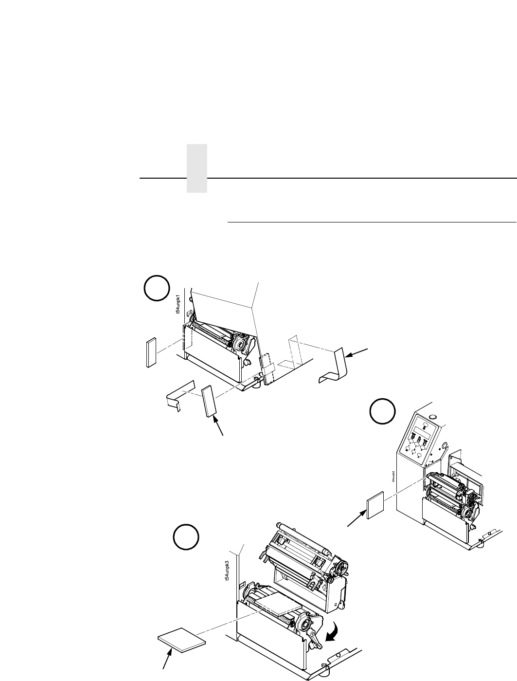
Removing The Internal Packing Material
Remove the tape strips and foam pads from the printer as indicated
below. (The top lid of the shipping carton also displays these
instructions.)
Tape Strips (2)
Foam Pads (2)
Foam Pad
Foam
A
B
C
Unlock
Installation
23
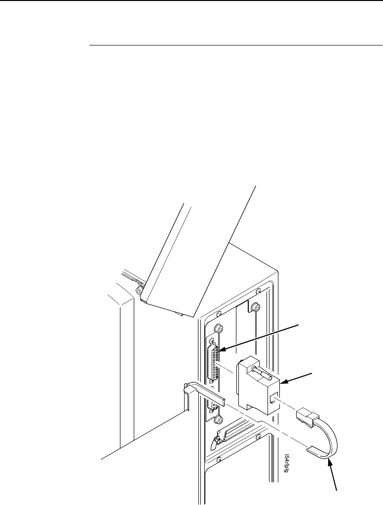
Installation
1. Place the printer on a flat level surface that allows easy access
to all sides of the printer.
CAUTION
Never operate the printer on its side or upside down.
2. Make sure the printer power switch is in the Off (O) position.
3. Install the serial interface adapter onto the serial interface
connector (as shown).
4. Plug the serial cable into the serial interface adapter.
Serial Interface
Connector
Serial Interface
Adapter
Serial Cable

Chapter 2 Controls And Indicators
24
WARNING
Failure to properly ground the printer may result in electric
shock to the operator.
In compliance with international safety standards, this printer
has been equipped with a three-pronged power cord. Do not
use adapter plugs or remove the grounding prong from the
cable plug. If an extension cord is required, ensure that a
three-wire cable with a properly grounded plug is used.
5. Attach the AC power cord to the AC power receptacle in the
back of the printer.
CAUTION
Verify the required voltage on the printer’s model number label
on the back of the printer.
6. Attach the AC power cord to a grounded (three prong) electrical
outlet of the proper voltage.
Controls And Indicators
Power Switch
The power switch is located on the bottom back panel of the printer.
To apply power, place the switch in the | (ON) position. When you
first power on the printer, a series of initialization messages will
appear on the Liquid Crystal Display (LCD) on the control panel.
To remove power, place the power switch in the O (OFF) position.
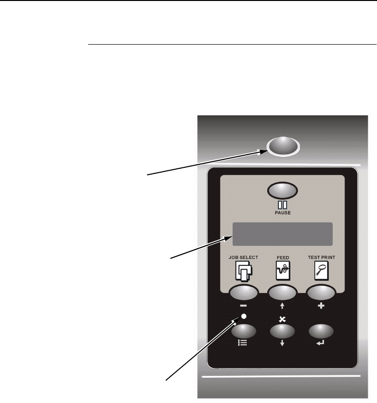
Control Panel
25
Control Panel
The control panel is located on the front of the printer and includes
an LCD, indicators, and control keys (buttons). These are
described in the following tables.
OFFLINE
Liquid Crystal
Display (LCD)
Online Status
Indicator
Job In Process
Indicator
Chapter 2 Controls And Indicators
26
Status And Display Indicators
Indicator Description Function in
Online Mode
Function in
Offline Mode
Function in
Menu Mode
Online Status Indicates when the
printer is online,
offline, or when
there is a fault
condition.
Stays lit when the
printer is online, ready
to print, and accept
data from the host.
Flashes during a fault
condition.
Off when the printer is
offline.
Flashes during a fault
condition.
Off.
Flashes during a fault
condition.
Liquid Crystal
Display (LCD)
A backlighted
liquid crystal
display with two
rows of 16
characters each.
Displays “ONLINE,”the
interface type, and
emulation in use.
During a fault condition,
displays the specific
fault message and the
corrective action.
Displays “OFFLINE.”
During a fault condition,
displays the specific
fault message and the
corrective action.
Displays “OFFLINE”
and a main menu,
submenu, or option.
During a fault condition,
displays the specific
fault message and the
corrective action.
Job In
Process
Indicates when the
printer is receiving
or processing
data.
Flashes when receiving
data.
Stays lit when data has
been processed and is
waiting to be printed.
Off when no data is
being received or when
no data remains in the
buffer.
Flashes when receiving
data.
Stays lit when data has
been processed and is
waiting to be printed.
Off when no data is
being received or when
no data remains in the
buffer.
None
Control Panel
27
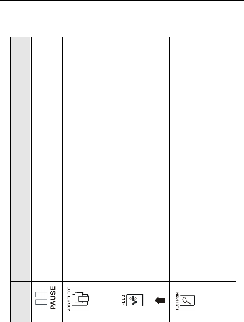
Control Panel Keys
Button Description Function in
Online Mode
Function in
Offline Mode
Function in
Menu Mode
PAUSE Key
Toggles the printer
between Online and
Offline modes.
Sets printer to
Offline mode.
Sets printer to Online mode. Sets printer to Offline mode.
JOB SELECT Key None Displays the name and
number of the last loaded
configuration and allows
you to load the factory and/
or pre-stored printer
configurations.
Scrolls left through main
menus.
Decrements option values
within submenus.
-DECREMENT Key in
Menu mode
FEED Key
UP Key in Menu mode
Advances the
media one label
length.
Advances the media one
label length.
Scrolls the current menu
selection one level up.
TEST PRINT Key
Pressing the ↵
(ENTER) key with a
Diagnostic Test
displayed initiates the
test. Pressing ↵ again
terminates the test.
None Scrolls through the Test
Print patterns.
Scrolls right through main
menus.
Increments option values
within submenus.
+INCREMENT Key in
Menu mode
Chapter 2 Controls And Indicators
28
Control Panel Keys (cont.)
Button Description Function in
Online Mode
Function in
Offline Mode
Function in
Menu Mode
CANCEL Key
When the CANCEL key is
enabled, pressing it will clear all
data in the printer buffer and
prevent printing of that data.
Note: The default = Disable.
However, when the Coax/
Twinax Interface option is
installed, the default = Enable.
DOWN Key in Menu mode
None Clears all data
in the printer
data buffer
when enabled.
Scrolls the current
menu selection one
level down.
MENU Key Takes the printer Offline and
selects the Menu mode.
Selects the
Menu mode.
Scrolls between main
menu selections.
ENTER Key
Pressing the ↵(ENTER) key in
Menu mode selects the
displayed option or value. An
asterisk then appears next to
the option or value indicating it
has been selected.
Note: If the ENTER key is
locked, “ENTER SWITCH
LOCKED”displays on the LCD
for one second. Press the
(DOWN) and ↵(ENTER) keys
at the same time to unlock the
ENTER key.
None None Selects the current
menu value and
displays an asterisk
(*) next to the value.
Loading Roll Media
29
LoadingMediaAndRibbon
IMPORTANT
Printronix recommends using the supplied starter roll of 100
labels to setup and verify printer operation. This will avoid
expending the more expensive smart labels for this task.
CAUTION
DO NOT TOUCH the printhead or the electronic components
under the printhead assembly.
CAUTION
Do not close the pivoting deck without label stock installed
between the printhead and the platen, because debris on the
platen may damage the printhead.
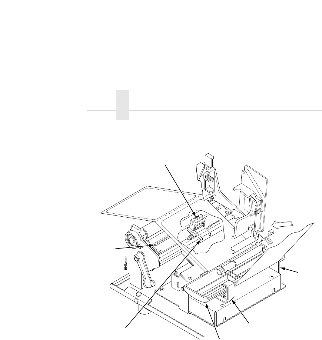
Loading Roll Media
1. Slide the media hanger guide outward to the end of the media
hanger, and flip it down into the horizontal position (as shown).
2. Open the pivoting deck by rotating the deck lock lever fully
clockwise.
Media Hanger
Media Hanger
Guide
Media Width
Guide
Deck Lock
Lever
Pivoting
Deck
Media Cover
PAUSE
Key
Liquid Crystal
Display (LCD)
RFID UHF Encoder
Media Damper
Chapter 2 Loading Media And Ribbon
30
3. Slide the media width guide close to the outside end of the
media damper.
4. Slide the media roll onto and towards the back of the media
hanger.
5. Place the media hanger guide under the media hanger and
against the lower part of the label core at a 45 degree angle
(as shown). This position provides the required tension for a
new label roll and the desired drag for a partial label roll.
Media Roll
Media Hanger
Guide
Media Hanger
Loading Roll Media
31
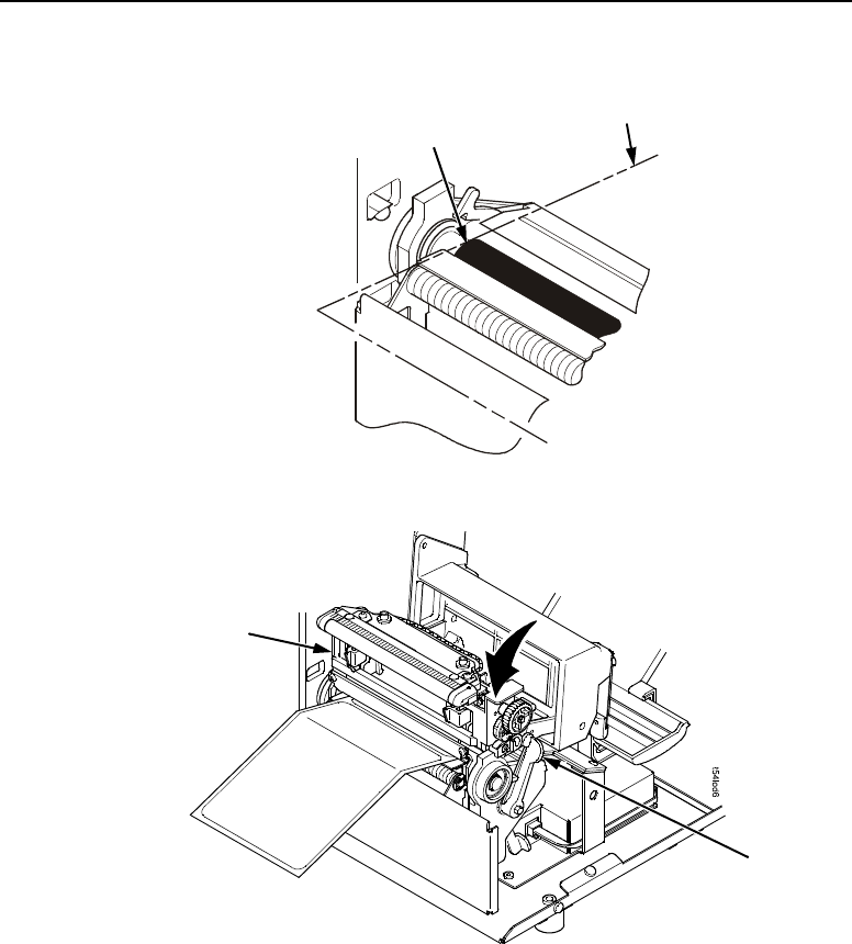
6. Raise the media damper.
7. Route the media as illustrated on the media and ribbon loading
instructions (or refer to the arrows on the printer frame).
NOTE: The media damper must be raised up and the media must
rest on top of the RFID UHF encoder.
Media and
Ribbon Loading
Instructions
Media Damper
RFID UHF Encoder
Media
Chapter 2 Loading Media And Ribbon
32
8. Lower the media damper.
9. Verify that the left edge of the media is against the fixed guide
on the bottom of the media damper.
10. Push the media width guide in until it is flush with the outer
edge of the media.
11. Check the horizontal position of the media sensor, and refer to
“Positioning The Media Sensors”on page 37.
Media
Guard
Media Sensor
Fixed
Guide
Media
Damper
Media Width
Guide
Media Sensor
Handle
Loading Roll Media
33
12. Align the left (inside) edge of the media with the left straight
edge of the platen (rubber drive roller).
13. Close the printhead by pressing down on the pivoting deck and
rotating the deck lock lever fully counterclockwise.
14. Power on the printer (place the power switch in the | position).
Platen (left edge) Media (left edge)
DeckLock
Lever
Pivoting
Deck
Chapter 2 Loading Media And Ribbon
34
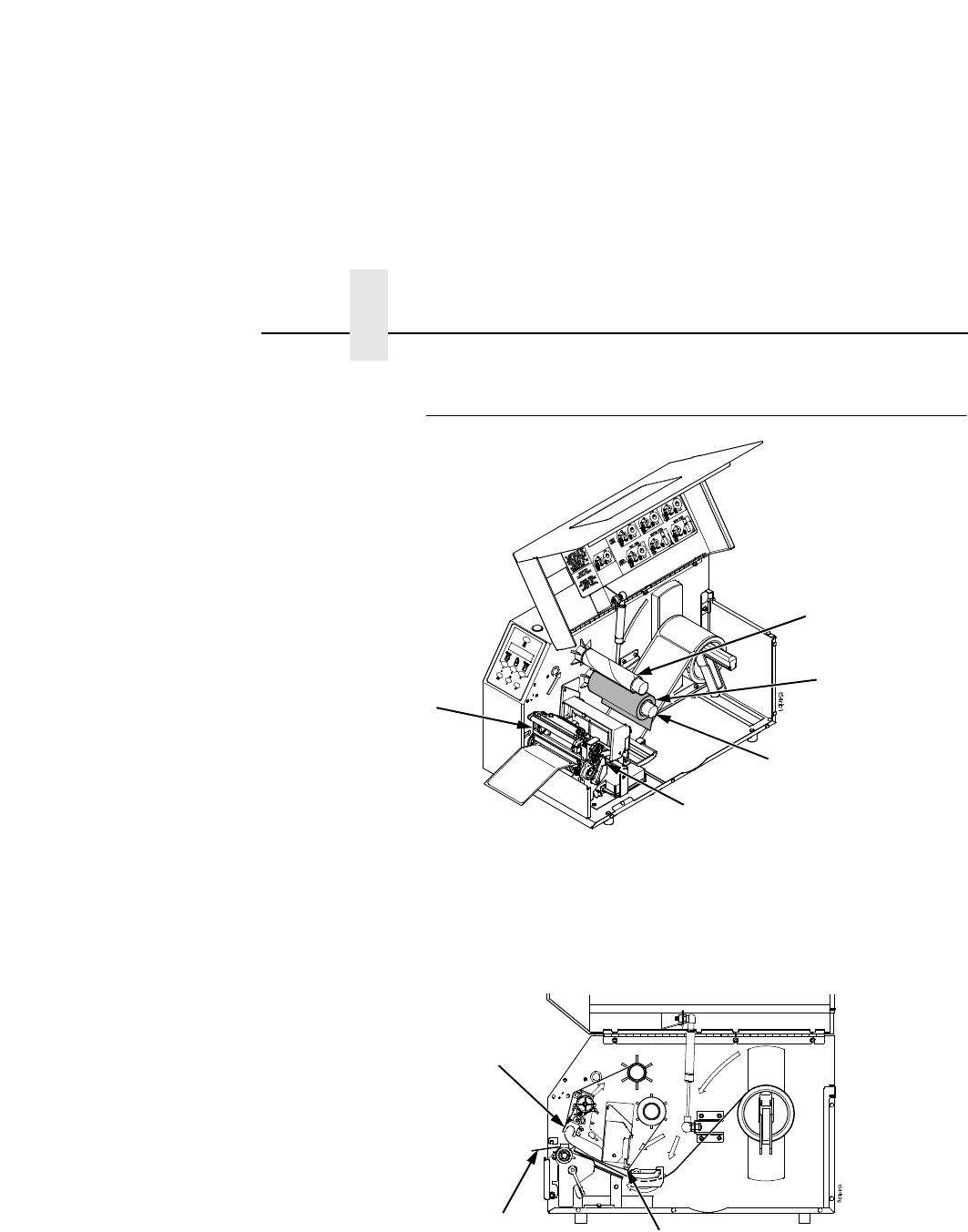
Loading Ribbon
1. Install the empty supply core on the take-up spindle.
2. Slide the ribbon roll onto the ribbon supply spindle until it stops
against the spindle flange.
3. Open the pivoting deck by rotating the deck lock lever fully
clockwise until the deck swings upward.
4. Thread the end of the ribbon under the rear ribbon guide roller,
then between the platen and the printhead.
Ribbon
Roll
Ribbon Supply Spindle
Deck Lock Lever
Pivoting
Deck
Empty Supply
Core
Media
Printhead
Rear Ribbon Guide Roller
Loading Ribbon
35
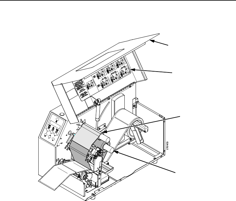
5. Route the ribbon using the media and ribbon loading
instructions on the media cover (or refer to the arrows on the
printer frame).
IMPORTANT
Do not attach the ribbon to the take-up spindle without a core
installed.
6. Attach the ribbon to the fiberboard core on the ribbon take-up
spindle using the adhesive on the ribbon leader.
7. Manually rotate the spindle clockwise until the clear leader has
passed the printhead.
8. Close the pivoting deck.
Take-up
Spindle
Take-up
Core
Media Cover
Media and
Ribbon Loading
Instructions
Chapter 2 Printing Adjustments
36
Printing Adjustments
Printhead Pressure Adjustment
Adjust the printhead pressure to the setting of 4.
Printhead Pressure Block Adjustments
Left Pressure Block
Manually adjust the left block so its handle is aligned with the bold
mark on the pressure block adjustment scale.
Right Pressure Block
Use the lead screw knob to position the right block with its pointer
near the right edge of the media in use.
Lead Screw
Knob
Right Pressure
Block Pointer
P
ressure
Bl
oc
k
Adjustment Scale
Left
Pressure
Block
Left
Pressure
Block
Handle
Right Pressure
Block
Printhead Pressure
Adjustment Dial
Positioning The Media Sensors
37
Positioning The Media Sensors
Your printer is equipped with upper and lower media sensors that
detect the top-of-form position on media with label length indicators
(gaps, notches, holes, or black marks). The media sensors also
detect Paper Out conditions.
Use the handles on the lower media sensor to horizontally position
it in the center of the installed media. Slide the upper sensor directly
over the lower sensor.
Running Auto Calibrate
Due to manufacturing differences in media and ribbon, the media
sensor may have difficulty distinguishing between the label and the
liner (gap).
To ensure proper operation, you must now run Auto Calibrate:
1. Power on the printer by pressing the power switch. (For the
location of the power switch and various panel keys, refer to
“Controls And Indicators”on page 24.)
2. Press the key until QUICK SETUP displays.
NOTE: For a complete description of the QUICK SETUP menu,
seepage40.
Media Sensor
Handle (2)
Media Sensor
.
.
.

Chapter 2 Saving The Configuration
38
3. If necessary, press ↓and ↵at the same time to unlock the ↵
key.
4. Press ↑or ↓until Gap/Mark Sensor / Disable* displays.
5. Press +or –until Gap displays.
6. Press ↵. An asterisk (*) displays next to Gap.
7. Press ↓until Auto Calibrate/Run Calibrate displays.
8. Press ↵. Media advances until it can accurately detect the label
length indicators and then stops at the top-of-form position. The
sensed distance value then displays for one second.
9. Auto Calibrate is successful when the sensed distance value
correctly matches that of the installed media. For the Gap
option, the sensed distance value is the physical length of one
label plus the length of one gap.
If GAP NOT DETECTED or PAPER OUT displays, check the
horizontal position of the media sensor (see “Positioning The
Media Sensors”on page 37), press PAUSE, and run Auto
Calibrate again.
10. Press the PAUSE key to take the printer offline.
11. Press the FEED key several times. Each time you press FEED,
the media should advance one label length and stop.
12. Once the sensed distance value and performance is confirmed,
save it to the desired configuration menu as described below
before powering off the printer.
Saving The Configuration
13. Press the key until QUICK SETUP displays.
14. Press ↑or ↓until Save Config./1* displays.
15. Press ↵. Saving Configuration displays briefly.
.
.
.

Positioning The Media Sensors
39
Run A Barcode Demo Test
IMPORTANT
Printronix recommends using the supplied starter roll of 100
labels to setup and verify printer operation. This will avoid
expending the more expensive smart labels for this task.
Before you send an actual print job, run a barcode demo test:
1. Press the PAUSE key until “OFFLINE”displays.
2. Press the TEST PRINT key until “Printer Tests/Barcode Demo”
displays.
3. Press ↵. The Barcode Demo test pattern will start and print two
barcodes.
4. Check the test pattern. If necessary, reposition the pressure
blocks to obtain a uniform print quality. In most cases, you will
need to adjust only the right pressure block.
5. If desired, you can run additional printer tests, such as Grey,
Grid, and Checkerboard. See step 1 above to start other tests.
NOTE: These tests default to run continuously. Press ↵to end the
test.
Chapter 2 QUICK SETUP Menu
40
QUICK SETUP Menu
QUICK SETUP
Validator Funct.6
Print Intensity
6ips* 2-10 ips1
Print Speed
Print Mode
Paper Feed Shift
Label Width
Label Length
Orientation
Transfer* Direct
4.1, 6.6, or 8.5 inches* 2, 4
Portrait* Landscape Inv. Portrait Inv. Landscape
-3* -15to15
00.1 to 8.5 inches4
0.00 inches* 2
4 or 6 inches* 2, 4 00.1 to 99.0 inches5
-0.50 to
X
inches3
Run Calibrate
Auto Calibrate
1* 1-8
Factory* 1-8
Save Config.
Power-Up Config.
Ver Image Shift
Hor Image Shift
0.00 inches* 2
-1.00to1.00inches0.00 inches* 2
-1.00 to
X
inches3
Enable* Disable
Tear-Off Strip* Tear-Off Peel-Off Cut
Media Handling Continuous
Gap/Mark Sensor Disable* Mark Gap Advanced NotchAdvanced Gap
Notes:
* = Default
1Maximum value depends on the width of the
printer model and printhead.
2You can change the unit value from inches to
millimeters under Units (in MEDIA CONTROL)
See the
T5000e User’s Manual
for information.
3Based on the current value setting for the Label
Length menu, up to a maximum of 12.80 inches.
4Maximum value depends on the width of the
printer model.
5Maximum value depends on model width and size
of DRAM installed.
6Appears only if the validator option is installed.
QUICK SETUP Submenus
41
QUICK SETUP Submenus
Print Intensity
Specifies the level of thermal energy from the printhead to be used
for the type of media and ribbon installed.
Large numbers imply more heat (thermal energy) to be applied for
each dot. This has a significant effect on print quality. The print
intensity and speed must match the media and ribbon type to
obtain the best possible print quality and barcode grades.
The range is -15 through +15:
•In Transfer mode, the default is -3.
•In Direct Thermal mode, the default is 0.
QUICK SETUP
(cont. from previous page)
SMT: Status
Toolset [1]* Toolset [1] to Toolset [4]
SMT: Sel Toolset
Disabled* Enabled
EPC1
zEPC2, 3
SMT: Select Tool
Notes:
* = Default.
1Appears only if Toolset [1] is selected under
SMT: Sel Toolset.
2Appears only if Toolset [2] is selected under
SMT: Sel Toolset.
3Undocumented options are reserved for internal
use and future design.
UPCA1
zUPCA2, 3 EAN81
zEAN82, 3 EAN131
zEAN132, 3 UCC1281
zUCC1282, 3
GTIN1
zGTIN2, 3

Chapter 2 QUICK SETUP Menu
42
Print Speed
Specifies the speed in inches per second (ips) at which the media
passes through the printer while printing.
The range is 2 through 10 ips (in increments of 1 ips).
The default is 6 ips.
NOTE: The maximum print speed varies based on maximum
printer width and dot per inch (dpi) resolution of the
printhead installed (203 or 300 dpi).
Print Mode
Specifies the type of printing to be done.
•Transfer. Indicates Thermal Transfer printing (ribbon installed).
•Direct. Indicates Direct Thermal printing (no ribbon) and
requires special heat sensitive media.
The default is Transfer.
Media Handling
Specifies how the printer will handle the media (labels or tag stock).
•Tear-Off Strip. Printer prints on the media and sends it out the
front until the print buffer is empty, then positions the last label
over the tear bar for removal.
•Tear-Off. After each label is printed, the printer positions the
label over the tear bar and waits for you to tear off the label
before printing the next one (on-demand printing). A “Remove
Label”message displays to remind you to remove the label
before the next one can be printed.
•Peel-Off. When the optional rewinder is installed, prints and
peels die-cut labels from the liner without assistance. The
printer waits for you to remove the label before printing the next
one (on-demand printing). The label liner is rewound on the
internal rewinder. A “Remove Label”message displays to
remind you to remove the label before the next one can be
printed.
•Cut. When the optional media cutter is installed, it
automatically cuts media after each label is printed or can cut

QUICK SETUP Submenus
43
after a specified number of labels have been printed using a
software cut command. It cuts continuous roll paper, labels, or
tag stock.
NOTE: This feature is currently not supported using the RFID UHF
encoder.
•Continuous. Printer prints on the media and sends it out the
front.
The default is Tear-Off Strip.
Paper Feed Shift
Represents the distance to advance a label (+ shift) or pull back
(–shift) when the Tear-Off Strip, Tear-Off, Peel-Off, or Cut Media
Handling option is enabled. The allowable range is -0.50 inches to
the current Label Length value setting up to a maximum of 12.80
inches in 0.01 inch increments.
The default is 0.00 inches.
Label Length
In most applications, the user-selected Label Length will match the
physical
label length. Physical label length is the actual label length
of the media installed. Following is a list of different media types:
•Die-cut labels –measurable length of the removable label
(leading edge to trailing edge). This does not include the
liner material or gap.
•Tag Stock with notches or holes –measurable length from
the trailing edge of one notch or hole to the trailing edge of
the next notch or hole.
•Tag Stock with black marks on the underside –measurable
length from the leading edge of one black mark to the
leading edge of the next black mark.
•Continuous media (no label length indicators) –
measurable length should be within + 1-2% of the Label
Length value entered.
Chapter 2 QUICK SETUP Menu
44
Label Width
The allowable range in inches is 00.1 to the maximum print width of
the printer. The allowable range in millimeters is 2.5 to the
maximum width of the printer.
Ver Image Shift
Specifies the amount to shift an image up (-) or down (+) for precise
positioning on the label. The actual height of the image is not
affected by this parameter. The allowable range is -1.00 inches to
the current Label Length value setting, up to a maximum of 12.80
inches in 0.01 inch increments.
The default value is 0.00 inches.
Hor Image Shift
Specifies the amount to shift an image left (-) or right (+) for precise
positioning on the label. The actual width of the image is not
affected by this parameter. The allowable range is -1.00 through
+1.00inchesin0.01inchincrements,displayedas
xx
/100.
The default value is 0.00 inches.
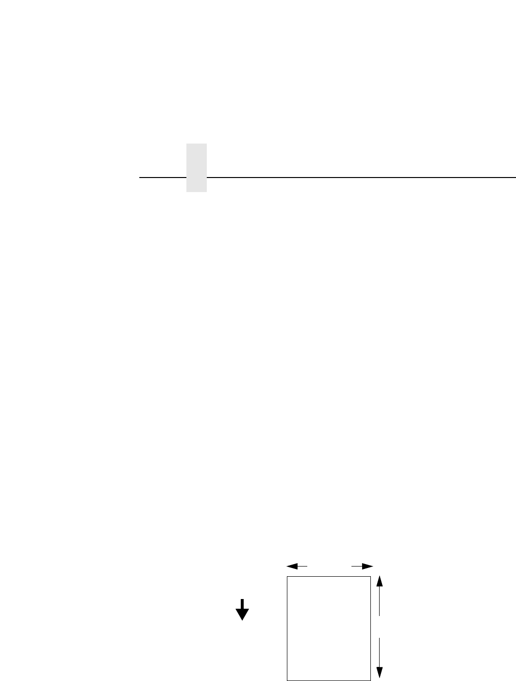
Orientation
Specifies the image orientation to be used when printing the label.
•Portrait. The default. Portrait refers to vertical page orientation,
where the height of a page is greater than its width. The top
edge of the image is parallel to the leading edge of the media.
The following example is viewed from the front of the printer.
4”
FEED
6”
The top edge of
the image is
parallel to the
leading edge of
the media.
Leading Edge
QUICK SETUP Submenus
45
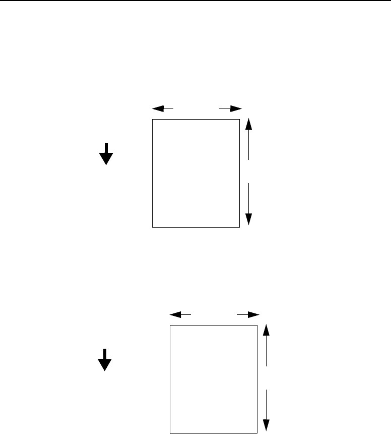
•Inv. Portrait. Inverse Portrait refers to vertical page orientation,
where the height of a page is greater than its width. The top
edge of the image is parallel to the trailing edge of the media.
The following example is viewed from the front of the printer.
•Landscape. Landscape refers to horizontal orientation, where
the width of a page is greater than its height. The top edge of
the image is parallel to the left edge of the media. The following
example is viewed from the front of the printer.
4”
FEED
6”
The top edge of
the image is
parallel to the
trailing edge of the
media.
Leading Edge
Trailing Edge
4”
FEED
6”
The top edge of
the image is
parallel to the left
edge of the media.
Leading Edge
Chapter 2 QUICK SETUP Menu
46
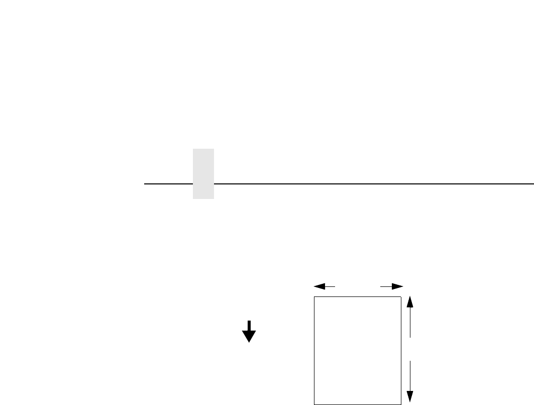
•Inv. Landscape. Inverse Landscape refers to horizontal
orientation, where the width of a page is greater than its height.
The top edge of the image is parallel to the right edge of the
media. The following example is viewed from the front of the
printer.
Gap/Mark Sensor
Specifies the sensor type needed for detecting the top-of-form
position on media with label length indicators (gaps, notches, holes,
or black marks).
•Disable. Select when using media with no label length
indicators (no gaps, notches, holes, or black marks), or when
you want the printer to ignore all existing label length indicators
on the installed media.
NOTE: When you select Disable, the length of each label is based
on the Label Length value entered.
•Mark. Select when using media that has horizontal black marks
located on the underside of the label liner or tag stock. The
top-of-form position is the leading edge of the black mark.
•Gap. Select when using media with a liner space between
die-cut labels or when using tag stock with notches or holes as
label length indicators on white background media. The
top-of-form position is the leading edge of the die cut label
(trailing edge of the gap, notch, or hole).
4”
FEED
6”
The top edge of
the image is
parallel to the right
edge of the media.
Leading Edge

QUICK SETUP Submenus
47
•Advanced Gap. Select when using media that has liner gaps
between die cut labels with black background. The top-of-form
position is the leading edge of the die cut label (trailing edge of
the gap, notch, or hole).
•Advanced Notch. Select when using media with notches or
holes that interrupt a black vertical line on the underside of the
media. The top-of-form position is the leading edge of the die
cut label (trailing edge of the gap, notch, or hole).
The default is Disable.
Auto Calibrate
This feature is used to improve the sensitivity and reliability of the
media sensor in detecting gaps, notches, holes, or black marks on
the installed media, as well as a Paper Out condition.
To initiate Auto Calibrate, scroll to the “Auto Calibrate”menu and
press the ↵key. The printer will advance media the distance
needed to accurately detect the label length indicators, then stop at
the top-of-form position and momentarily display the Sensed
Distance. This process will take a few seconds and will result in an
update of the printer values.
Auto Calibrate is completed successfully when the Sensed
Distance displayed correctly matches that of the installed media.
When you select Gap, the Sensed Distance should match the
length from the trailing edge of one gap to the trailing edge of the
next gap (one label + one gap). When you select Mark, the Sensed
Distance should match the length from the leading edge of one
black mark to the leading edge of the next black mark.
Auto Calibrate supports label lengths up to 24 inches.
Validator Funct.
This menu appears only if the validator option is installed.
•Enabled. The printer will command the validator to begin
scanning and errors will be reported. The counters will be
incremented while the validator is enabled.

Chapter 2 QUICK SETUP Menu
48
•Disabled.The printer will not command the validator to begin
scanning and no errors will be reported. The counters will not
be incremented while the validator is disabled.
NOTE: If you save a configuration with the validator enabled,
power down and power up, and the validator is not
connected or not functioning, the error message “Validator
not communicating”will display briefly. The Validator menu
will not display.
If the validator is installed, the default is Enable.
Save Config.
Allows you to save up to eight unique configurations to meet
different print job requirements. This eliminates the need to change
the parameter settings for each new job. The configurations are
stored in memory and will not be lost if you turn off the printer. The
default is 1.
Power-Up Config.
You can specify one of the eight configurations as the power-up
configuration. The default is Factory.
SMT: Status
This menu appears only if the RFID UHF encoder is installed. See
“Software Migration Tools (SMT)”on page 63.
•Disabled.The printer will disable the use of the Software
Migration Tools.
•Enabled. The printer will enable the use of the Software
Migration Tools.
SMT: Sel Toolset
This menu appears only if the RFID UHF encoder is installed. See
“Software Migration Tools (SMT)”on page 63.
•Toolset [1].SMTsforPGL
®emulation.
•Toolset [2]. SMTs for PPI1 emulation.
•Toolset [3] and Toolset [4]. Reserved for internal use and
future design.

QUICK SETUP Submenus
49
SMT: Select Tool
This menu appears only if the RFID UHF encoder is installed. See
“Software Migration Tools (SMT)”on page 63.
•EPC,GTIN,UPCA,EAN8,EAN13,andUCC128.SMTs
displayed if Toolset [1] is selected under SMT: Sel Toolset.
•zEPC,zGTIN,zUPCA,zEAN8,zEAN13, and zUCC128.SMTs
displayed if Toolset [2] is selected under SMT: Sel Toolset.
NOTE: Undocumented options are reserved for internal use and
future design.
For More Information
This chapter has provided general information for use of your
printer. The next chapter provides information about the RFID UHF
encoder.
Please refer to your
User’s Manual
for more detailed information
including:
•Other Configuration Menus
•Interfaces
•Diagnostics and Troubleshooting
•Printer Options
•Specifications
•Glossary of Terms

Chapter 2 For More Information
50

51
3Smart Label
Development
Overview
This chapter describes how to use the T5000e thermal printer RFID
UHF encoder. The RFID UHF encoder is designed to be
transparent to the printer operation. It provides the capability of
programming smart labels (with embedded RFID UHF tags) while
printing the label format. The smart labels are provided with the
printer or purchased separately from Printronix.
There are several ways to program RFID tags in smart labels:
•Use the Software Migration Tools (SMT) to enable the printer to
automatically create RFID commands from your existing bar
code commands. These tools are described on page 63.
•Incorporate RFID commands into new or existing Printronix
PGL programs. Command details start on page 55.
•Incorporate RFID commands into new or existing ZPL™
programs. By selecting the Printronix PPI1 emulation you can
seamlessly upgrade from Zebra™printers. Command details
start on page 60.
Chapter 3 RFID CONTROL Menu
52
RFID CONTROL Menu
RFID CONTROL
Reader
Class 1*
None
Tag Type
Error Handling
Tag Write Cnt1
Clear Tag Stat
Failed Tag Cnt1
Overstrike* Stop
Enable* Disable
Label Retry
Notes:
* = Default.
Italicized items are available only when you enable
Admin User in the PRINTER CONTROL menu.
1Display item only.
5* 0to5
RFID Test
F/W-Version1
Auto Retry
3
*
0to8

RFID CONTROL Submenus
53
RFID CONTROL Submenus
Reader
This menu item allows the user to enable or disable the RFID UHF
encoder. The default is Enable.
Tag Type
This menu item allows the user to specify the tag type in use. The
default is Class 1. Other classes may be added in the future.
Error Handling
This menu item allows the user to disable the printing of the
Overstrike pattern for a failed label. The default is Overstrike.
In Overstrike mode, each failed label prints with the Overstrike
pattern and the form retries until the Label Retry count is
exhausted. At this time, the error message “RFID Error: Check
System”displays. The failed label will not be reprinted.
In Stop mode, when a tag fails to be programmed the printer will
halt and display the error message “RFID Error: Check Media.”The
label will be discarded and reprinting of the label (if desired) must
be initiated from the host. When the error is cleared, the label with
the failed tag moves forward until the next label is in position to be
printed.
In None mode, no specific action is taken when a tag fails to be
progammed.
Label Retry
This menu item allows the user to specify the number of label
retries that the RFID UHF encoder will attempt before declaring a
fault indicating a problem with the RFID UHF encoder, the
assembly antenna, the printer setup, or the label stock. Label Retry
only applies when the Error Handling mode is Overstrike. The
default is 5.
In the Overstrike mode, each failed label prints with the Overstrike
pattern and the form retries until the label retry count is exhausted.
At this time, the error message “RFID Error: Check System”
displays. The failed label will not be reprinted.

Chapter 3 RFID CONTROL Menu
54
Tag Write Cnt
This menu item displays the number of tags written since the last
Clear Tag Stat operation has been initiated. (See “Clear Tag Stat”
below.)
Failed Tag Cnt
This menu item displays the number of failed tag write attempts
since the last Clear Tag Stat operation has been initiated. (See
“Clear Tag Stat”below.)
Clear Tag Stat
This menu item clears the Tag Write Cnt and Failed Tag Cnt menu
items when selected.
Admin User Menu Items
To see these menu items, set Admin User to Enable in the
PRINTER CONTROL menu. (Refer to the
User’s Manual
.)
IMPORTANT
Admin User menu items should only be used for
troubleshooting.
RFID Test
This menu item reads the tag in range of the internal RFID antenna
and reports the tag data to the debug port and momentarily
displays it on the operator panel. It is primarily intended for
development verification by checking that the system is working.
Auto Retry
This menu item allows the user to specify the number of automatic
(internal) retries that the RFID UHF encoder will attempt before
declaring a tag error. The default is 3.
F/W-Version
This menu item displays the reader firmware version.

Write Tag
55
RFID PGL Commands
Write Tag
Purpose To program non-incremental data into an RFID tag
(embedded in the smart label).
MODE CREATE
Format
RFWRITE;[HEX;][EPC
m
;][RF
n
;L;][LOCK;]AT
p
;[(D)
datafield
(D)]
RFWRITE; The RFID Write Tag command.
HEX; Optional parameter to indicate that the
text in
datafield
is in hexadecimal format
and that it will be converted to binary
format.
EPC
m
; Optional parameter to indicate that the
data in
datafield
should be converted to
an EPC number. When this parameter is
used, the HEX option is automatically
enabled and the data field is limited to a
maximum of 14 digits. The AT parameter
is ignored. The tag is then programmed
as follows:
Bits 0 to 1 are programmed with the
EPC value 0 to 3, specified in
m
.
Bits 2 to 57 are programmed with the
hexadecimal characters in the data field
(14 maximum). If the data field has less
than 14 hexadecimal characters, zeros
are assumed for the remaining digits.
Bits 58 to 63 are set to zero.
RF
n
;
L
; Optional parameter to indicate that this
field has dynamic data. Replace
n
with a
number ranging from 1 to 512 to identify
the field number of this RFWRITE field.
Replace
L
with the length of the dynamic
data string. If this option is used, the

Chapter 3 RFID PGL Commands
56
datafield
is ignored, and dynamic data
must be entered via the RF command in
the EXECUTE mode. The length of the
dynamic data must be equal to
L
.
LOCK; Optional parameter to write-protect the
data. Currently not supported.
AT
p
;
p
specifies the decimal start position
where data will be written to the tag.
Subsequent bits will be shifted and
previous bits are nulled.
(D) Delimiter designating the start and end of
static data for the RFWRITE field.
Replace (D) with any printable character,
except the SFCC and “/”(the slash
character).
datafield
The static data of the RFWRITE field.
NOTE: RFWRITE fields are not expandable in VDUP and/or
HDUP sections.
Example 1
Program a tag with “HELLOTAG”.
~CREATE;HELLO
// Create a form named HELLO.
RFWRITE;AT1;*HELLOTAG*
// RFID Write Tag command with static data. Data will
// be at the first location of the tag. The static data is
// “HELLOTAG”.
END
// Terminate HELLO form creation.
~EXECUTE;HELLO
// Execute HELLO form.
~NORMAL
// Back to normal mode.

Write Tag
57
Example 2
Another version of Example 1 using the HEX parameter.
~CREATE;HELLO
RFWRITE;HEX;AT1;*48454C4C4F544147*
END
~EXECUTE;HELLO
~NORMAL
Example 3
Program a tag using the EPC parameter 1. This results in the tag
having the first two bits = 01, next 56 bits with hexadecimal values
“01234567890123”, and last 6 bits = 0.
~CREATE;HELLO
RFWRITE;EPC1;AT1;*01234567890123*
END
~EXECUTE;HELLO
~NORMAL
Example 4
Write tag command with dynamic non-incremental data
“HELLOTAG”.
~CREATE;DYNATAG
// Create a form named DYNATAG.
RFWRITE;RF1;8;AT1;
// RFID Write Tag command with dynamic
// non-incremental data. The 8-byte data will be at the
// first location of the tag.
END
// Terminate DYNATAG form creation.
~EXECUTE;DYNATAG
~RF1;*HELLOTAG*
// Execute the DYNATAG with the dynamic data
// “HELLOTAG”.
~NORMAL
// Back to normal mode.

Chapter 3 RFID PGL Commands
58
Read Tag
Read Tag is not a command, but an element of the ALPHA and
BARCODE commands. See “Alphanumerics”and “Bar Codes”in
the
IGP/PGL Programmer’s Reference Manual
for more
information.
Purpose Embed RFID data into an ALPHA or BARCODE data
field.
Format <RDI>
position,length[,format];
<RDI> The RFID Data Indicator character, as
defined by the RFREAD parameter in the
ALPHA or BARCODE commands. See
the ALPHA and/or BARCODE command
description for details.
position
The decimal number that specifies the
starting position of the data inside the
transponder.
length
The decimal number that specifies the
length of the data to be read.
format
Replace the optional
format
parameter
with any non-zero number to convert the
data to hexadecimal format.
Example
Write tag contents, then read and insert the tag contents into an
ALPHA field.
~CREATE;READTAG
// Create the READTAG form.
RFWRITE;AT1;*HELLOTAG*
// Program the string “HELLOTAG”into the tag
ALPHA
// The following ALPHA element is defined below:
RFREAD@;AF1;27;3;5;0;0
// RFID Data Indicator character is “@”.
// Dynamic field number of this ALPHA element is 1.
STOP
// Terminate the ALPHA element definition.

Read Tag
59
BARCODE
// The following BARCODE element is defined below:
C3/9;RFREAD@;BF1;10;5;5
// Code 3 of 9 bar code; the RFID Data Indicator
// character is “@”.
PDF
// Dynamic bar code field number is 1; display the
// readable part.
STOP
// Terminate the BARCODE element definition.
END
// Terminate the READTAG form creation.
~EXECUTE;READTAG
~AF1;*DATA FROM 0 TO 7 = @1,8;*
// Execute READTAG form with dynamic and RFID
// data from the first eight bytes inside the tag, using the
// RFID Data Indicator character, which is “@”.
// Since we programmed that tag with “HELLOTAG”,
// the string is “DATA FROM 0 TO 7 = HELLOTAG”is
// printed.
~BF1;*@1,5,1;*
// Read the first five bytes from the tag, which is
// “HELLO”, and convert it to hexadecimal format,
// which is “48454C4C4F”. Next, attach the hex format
// data to the bar code. The 3 of 9 bar code containing
// the data “48454C4C4F”is printed.
~NORMAL
// Complete the EXECUTE mode, and return to
// NORMAL mode.

Chapter 3 RFID PPI1 Commands
60
RFID PPI1 Commands
Get Tag Unique ID
Purpose Read the unique identification number of the RFID tag
(embedded in the smart label).
Format ^RI
x
^RI Get Tag Unique ID command.
x
The field number to which the data will
be assigned. The default is 0, and other
acceptable values range from 1 to 9999.
Comments
The PPI1 only supports Alien Technology Class 1a
tags, which do not have the unique identification
numbers. Therefore, the PPI1 absorbs this command.
Set Tag Type
Purpose Select the type of the RFID tag (embedded in the smart
label).
Format ^RS
x
^RS Set Tag Type command.
x
Number assigned to the type of the tag.
The default is 0, and other acceptable
values range from 1 to 9999.
Comments
The PPI1 only supports Alien Technology Class 1a
tags. There are no alternative choices. Therefore, the
PPI1 absorbs this command.

Read Tag
61
Read Tag
Purpose This command allows data from the RFID tag
(embedded in the smart label) to merge into any
previously defined dynamic data field. It is equivalent to
the Field Number command (^FN) except that the data
come from the RFID tag.
Format ^RT
x
,
startblock
,
length
,
hexformat
,
retriescount
,
nomotionflag
,
reservedflag
^RT Read Tag command.
x
The field number to which the data will
be assigned. The default is 0, and other
acceptable values range from 1 to 9999.
startblock
Location where data will be read from the
RFID tag. The PPI1 only supports Alien
Technology Class 1a tag, which has only
one 8–byte block. Therefore,
startblock
will be set to 0, regardless of the
specified value.
length
Thenumberofblockstobereadfromthe
RFID tag. The PPI1 only supports Alien
Technology Class 1a tags, which have
only one 8–byte block. Therefore,
length
will be set to 1, regardless of the
specified value.
hexformat
This flag indicates whether the data, after
being read from the RFID tag, should be
translated into hexadecimal format. The
default is 0, meaning the data will not be
translated. The other acceptable value is
1, meaning the data will be translated
into hexadecimal format.
retriescount
The number of automatic attempts to
read data from the tag if previous reads
failed. The PPI1 absorbs the number and
uses the value on the operator panel.

Chapter 3 RFID PPI1 Commands
62
nomotionflag
Set this flag to 1 to read data from the tag
without moving the label. The PPI1 does
not move the label regardless of the
value. The user needs to print something
on the label to eject the label.
reservedflag
This is a reserved flag. The PPI1 absorbs
this number.
Comments
This command is only executed by the demand for
data from any dynamic field. The PPI1 absorbs this
command if there are no demands for the data.
Write Tag
Purpose This command programs data into an RFID tag
(embedded in the smart label).
Format ^WT
startblock
,
retriescount
,
nomotionflag
,
writeprotect
,
reservedflag
^WT Write Tag command.
startblock
Location of data in the RFID tag. The
PPI1 only supports Alien Technology
Class 1a tags, which have only one 8–
byte block. Therefore,
startblock
will be
set to 0, regardless of the specified
value.
retriescount
The number of automatic attempts to
write data into the tag if previous writes
failed. The PPI1 absorbs the number and
uses the value on the operator panel.
nomotionflag
Set this flag to 1 to program data into the
tag without moving the label. The PPI1
does not move the label regardless of the
value. The user needs to print something
on the label to program the data into the
tag and eject the label.
writeprotect
This flag indicates whether the data
should be protected from being
overwritten later. The default is 0,

Tools List
63
meaning the data are not protected. The
other acceptable value is 1, meaning the
data are protected. The PPI1 absorbs
this number and does not protect the
data.
reservedflag
This is a reserved flag. The PPI1 absorbs
this number.
Software Migration Tools (SMT)
There are SMTs for six separate end-use applications supporting
both PGL and PPI1 datastreams for a total of 12 tools. Each tool
intercepts bar code data in a host datastream and copies the data
to an RFID tag (embedded in a smart label) according to a set of
rules as defined below. SMTs assume that only one bar code of the
type being processed is present. In the event that there is more
than one of a given type of barcode present, only the first is
processed.
Bar code information encoded as dynamic data is supported. To
avoid ambiguity, where bar code data is provided in the form of
dynamic data, the RFID tag will be encoded with only the contents
of the first variable bar code field. It will be your responsibility to
ensure that the first variable bar code is the desired bar code.
Tools List
•GTIN: According to Uniform Code Council standards there are
two permissible bar codes on standard case labels: UCC-128
and Interleaved Two of Five (ITF14). These are the typical bar
code carriers for the GTIN (Global Trade Identification
Number). This tool copies data from either an ITF14, or from a
UCC-128 barcode with an Application Identifier of 01 (which
indicates an SCC-14) to an RFID tag. If barcode checksum
data is included in your datastream, it will be encoded onto the
tag. If your datastream requests the printer to calculate the bar
code checksum, it will not be encoded onto the tag. In the case
of the UCC bar code, the (01) application identifier is not written
to the tag. Data written to the RFID tag is right justified and zero
padded.

Chapter 3 Software Migration Tools (SMT)
64
•UCC128: Copies data from a UCC-128 bar code with an
application identifier (AI) in the range of 90-99 to an RFID tag.
These AI’s are reserved for internal applications. The AI is not
written to the RFID tag. Data written to the RFID tag is right
justified and zero padded. Checksum data calculated by the
printer is not encoded onto the tag. Bar code data beyond the
16th digit is truncated without an error message.
•EAN8: Copies data from an EAN8 bar code to an RFID tag.
EAN 8+2 and EAN 8+5 variants are both supported. Data
written to the RFID tag is right justified and zero padded.
Checksum data calculated by the printer is not encoded onto
the RFID tag.
•EAN13: Copies data from an EAN13 bar code to an RFID tag.
EAN 13+2 is also supported but EAN 13+5 variant is not
supported. Data written to the RFID tag is right justified and
zero padded. Checksum data calculated by the printer is not
encoded onto the RFID tag.
•UPC-A: Copies data from an UPC-A, UPC-A+2 or UPC-A+5
bar code to an RFID tag. Data written to the RFID tag is right
justified and zero padded. Checksum data calculated by the
printer is not encoded onto the RFID tag.
•EPC: This tool allows EPC data carried by a Code 3 of 9 bar
code to be encoded onto an RFID tag. Data beyond the 16th
digit is not allowable for an EPC and is truncated. Data must be
numeric only.
•zGTIN,zEPC,zUCC-128,zEAN8,zEAN13,and zUPC-A:
These are all PPI1 emulation specific tools identical in function
to those of their corresponding names above.
NOTE: Dynamic data is variable data entered into specific
locations on each form definition. Each time the form prints,
a single command enters new data into those locations
supplied in the datastream after form definition has been
completed.

Selecting The Tools
65
Selecting The Tools
1. Press until QUICK SETUP displays.
2. If necessary, press ↓and ↵at the same time to unlock the ↵
key.
3. Press ↓until SMT: Sel Toolset displays.
4. Press ↓until Toolset [1] (PGL emulation) or Toolset [2] (PPI1
emulation) displays.
5. Press ↵to select it.
6. Press ↓until SMT: Select Tool displays.
7. Press ↓until the desired tool displays.
8. Press ↵to select it.
9. Press ↓and ↵at the same time to lock the ↵key, then press
PAUSE to take the printer offline.
10. Press PAUSE again to put the printer online.
.
.
.

Chapter 3 Error Messages
66
Error Messages
The RFID UHF encoder can detect a number of errors. When one
of these errors occurs, the RFID UHF encoder alerts the printer to
perform the currently selected error action (see “Error Handling”on
page 53) and show the appropriate error message on the printer
display. RFID UHF encoder error messages are explained in
Table 1.
Table 1. Error Message List
Error Message Explanation Solution
RFID MAX RETRY
Check System
Error Handling = Overstrike in
the RFID CONTROL menu,
and the Label Retry count has
been exhausted.
Press PAUSE to clear the
message.
See “Troubleshooting”on
page 67.
RFID Reader
Comm Error
RFID error: communication
cannot be established with
the RFID UHF encoder.
Reader will be set to Disable
in the RFID CONTROL menu
and the previous port settings
restored.
Press PAUSE to clear the
message.
See “Troubleshooting”on
page 67.
RFID TAG FAILED
Check Media
Error Handling = Stop in the
RFID CONTROL menu, and
the RFID UHF encoder could
not read the RFID tag.
Press PAUSE to clear the
message.
See “Troubleshooting”on
page 67.

Selecting The Tools
67
Troubleshooting
If you are having trouble with the RFID UHF encoder, consult
Table 2 for a list of symptoms and possible solutions.
Table 2. Troubleshooting the RFID UHF Encoder
Symptom Solution
No communication between the
printer and the reader
1. Make sure the serial interface adapter and
the serial cable are plugged into the printer.
See “Installation”on page 23.
2. Make sure Reader = Enable in the RFID
CONTROL menu.
3. Use the RFID Test option in the RFID
CONTROL menu (Admin User enabled) to
read and display the current RFID tag
content. RFID tags usually contain a valid
entry due to the pre-test process. See “RFID
Test”on page 54.
Tag failed 1. The label could be misaligned. Perform the
Auto Calibrate procedure (page 37).
2. Make sure the media are smart labels with
RFID tags located in the correct position.
3. The RFID tag could be defective. Try
another tag.
4. Make sure the application does not send too
few or too many digits to the RFID tag.
Inconsistent results Make sure the media is loaded correctly and
passes smoothly over the antenna. See
“Loading Media And Ribbon”on page 29.
The RFID UHF encoder works,
but it does not meet expectations
Make sure that both Error Handling and Label
Retry are set to desired values in the RFID
CONTROL menu.

Chapter 3 Troubleshooting
68

69
A
Auto Calibrate
option, 47
running, 37
B
Barcode demo test, 39
C
Configuration, saving, 38
Control panel, 25
E
Error Handling, 53
Error messages, 66
RFID MAX RETRY / Check System, 66
RFID Reader / Comm Error, 66
RFID TAG FAILED / Check Media, 66
F
For more information, 49
G
Gap/Mark Sensor option, 46
Get Tag Unique ID PPI1 command
code, 60
H
Hor Image Shift option, 44
I
Industry web links, 19
J
Job In Process indicator, 25
L
Label Length option, 43
Label Retry, 53
Label Width option, 44
LCD, 25
Limitations, 15
Liquid Crystal Display (LCD), 25
Loading
ribbon, 34
roll media, 29
M
Media Handling option, 42
Media sensor, positioning, 37
Media, roll, 29
O
Online Status indicator, 25
Ordering smart labels, 17
Orientation option, 44
Overstruck smart labels, 15
Index

Index
70
P
Paper Feed Shift option, 43
PGL commands, 55
Positioning the media sensor, 37
Power switch, 24
Power-Up Config. option, 48
PPI1 commands, 60
Print Intensity option, 41
Print Mode option, 42
Print Speed option, 42
Printer
installation, 23
unpacking, 21
Printhead pressure block adjustments, 36
Printing adjustments, 36
Q
QUICK SETUP
menu, 40
submenus, 41
R
Read Tag PGL command code, 58
Read Tag PPI1 command code, 61
Reader, 53
RFID CONTROL
menu, 52
submenus, 53
RFID MAX RETRY / Check System, 66
RFID PGL commands, 55
RFID PPI1 commands, 60
RFID Reader / Comm Error, 66
RFID TAG FAILED / Check Media, 66
RFID tags, 51
RFID UHF encoder, 51
Ribbon, loading, 34
Roll media, 29
Run a barcode demo test, 39
Runningautocalibrate,37
S
Save Config. option, 48
Saving the configuration, 38
Selecting the Software Migration Tools
(SMT), 65
Set Tag Type PPI1 command code, 60
Smart label development overview, 51
Smart labels, 51
limitations, 15
ordering, 17
overstruck smart labels, 15
performance, 14
SMT
Sel Toolset option, 48
Select Tool option, 49
Status option, 48
Software Migration Tools (SMT), 63
introduction, 16
selecting, 65
tools list, 63
T
Tag Type, 53
Troubleshooting, 67


Index
72

Printronix, Inc.
14600 Myford Road
P.O. Box 19559
Irvine, CA 92623-9559
Phone: (714) 368-2300
Fax: (714) 368-2600
Customer Support Center: (714) 368-2686
Printronix
Nederland BV
P.O. Box 163, Nieuweweg 283
NL-6600 Ad Wijchen
The Netherlands
Phone: (31) 24 6489489
Fax: (31) 24 6489499
Printronix Schweiz GmbH
42 Changi South Street 1
Changi South Industrial Estate
Singapore 486763
Phone: (65) 6542-0110
Fax: (65) 6543-0220
Visit our web site at:
www.printronix.com
Copyright 2003 Printronix, Inc.
177393-001A
*177393-001*