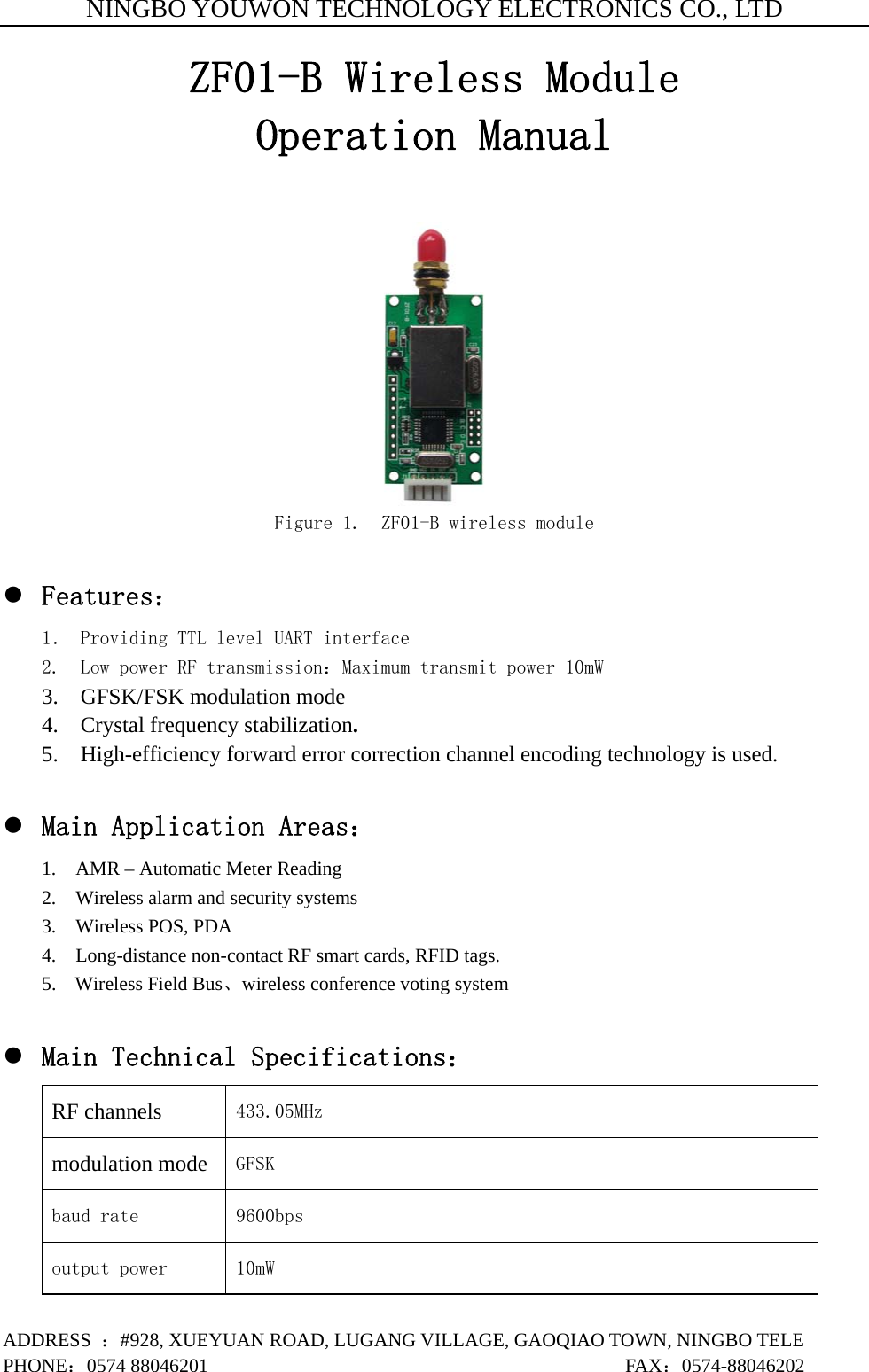
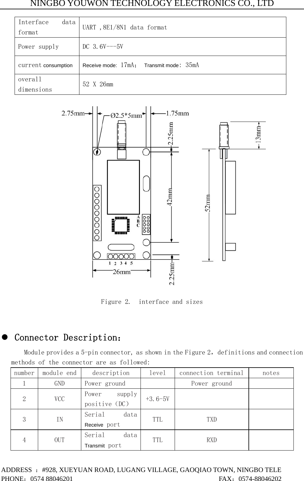
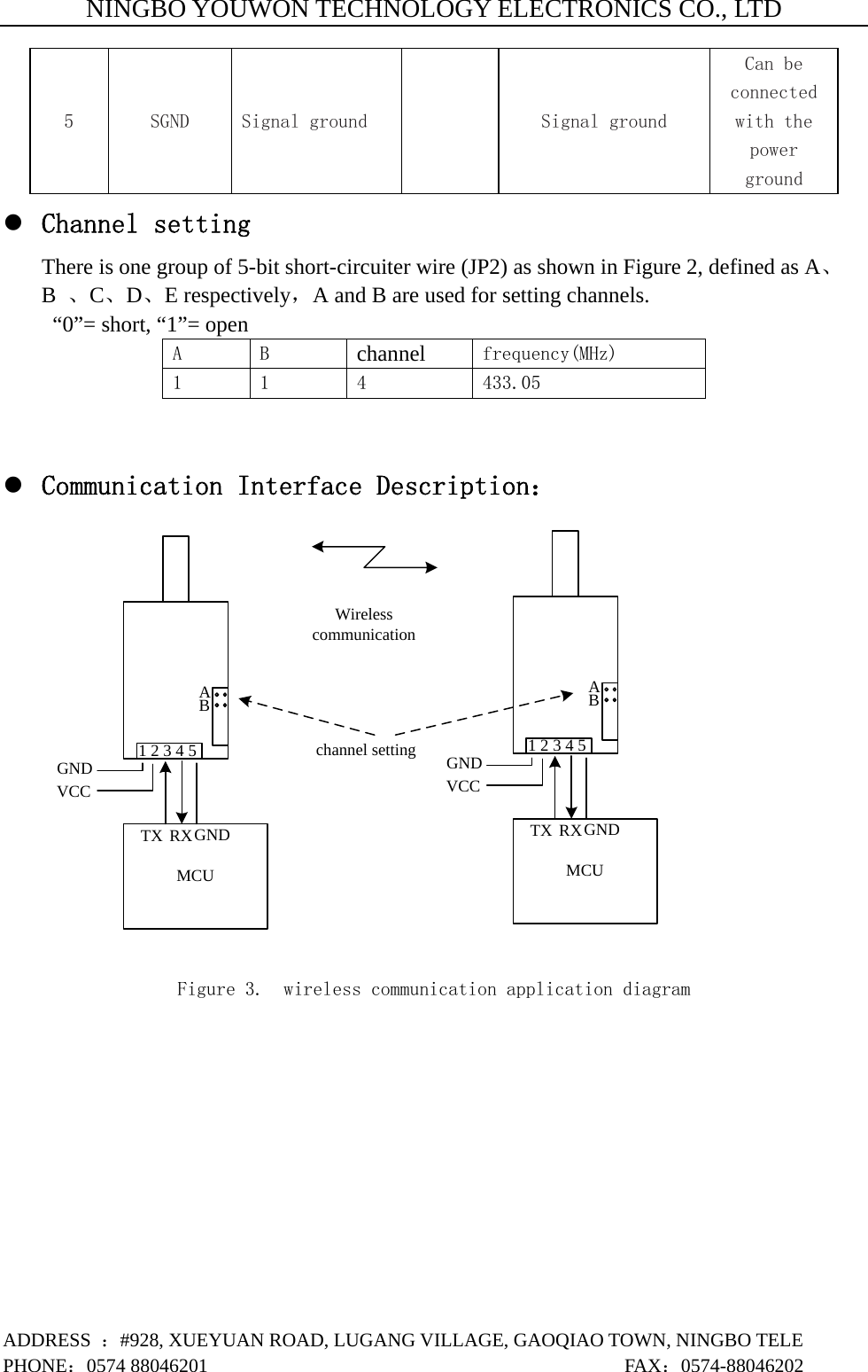
Pro Lite ZF01-B DATA TRANSCEIVER User Manual ZF01 B EN

Pro-Lite, Inc. DATA TRANSCEIVER ZF01 B EN

Users Manual

NINGBO YOUWON TECHNOLOGY ELECTRONICS CO., LTD ADDRESS  :#928, XUEYUAN ROAD, LUGANG VILLAGE, GAOQIAO TOWN, NINGBO TELE PHONE:0574 88046201                                           FAX:0574-88046202 ZF01-B Wireless Module Operation Manual   Figure 1.  ZF01-B wireless module  z Features: 1. Providing TTL level UART interface 2.  Low power RF transmission:Maximum transmit power 10mW 3.  GFSK/FSK modulation mode 4.  Crystal frequency stabilization. 5.    High-efficiency forward error correction channel encoding technology is used.  z Main Application Areas: 1.    AMR – Automatic Meter Reading 2.    Wireless alarm and security systems 3.  Wireless POS, PDA  4.    Long-distance non-contact RF smart cards, RFID tags. 5. Wireless Field Bus、wireless conference voting system    z Main Technical Specifications: RF channels 433.05MHz  modulation mode GFSK  baud rate 9600bps output power 10mW
NINGBO YOUWON TECHNOLOGY ELECTRONICS CO., LTD ADDRESS  :#928, XUEYUAN ROAD, LUGANG VILLAGE, GAOQIAO TOWN, NINGBO TELE PHONE:0574 88046201                                           FAX:0574-88046202 Interface  data format UART ,8E1/8N1 data format Power supply  DC 3.6V---5V current consumption Receive mode: 17mA; Transmit mode: 35mA overall dimensions  52 X 26mm    Figure 2.  interface and sizes   z Connector Description: Module provides a 5-pin connector, as shown in the Figure 2,definitions and connection methods of the connector are as followed: number  module end description  level  connection terminal  notes 1  GND  Power ground   Power ground   2  VCC  Power  supply positive(DC)  +3.6-5V   3  IN  Serial  data Receive port  TTL  TXD   4  OUT  Serial  data Transmit port  TTL  RXD
NINGBO YOUWON TECHNOLOGY ELECTRONICS CO., LTD ADDRESS  :#928, XUEYUAN ROAD, LUGANG VILLAGE, GAOQIAO TOWN, NINGBO TELE PHONE:0574 88046201                                           FAX:0574-88046202 5  SGND  Signal ground   Signal ground Can be connected with the power ground z Channel setting There is one group of 5-bit short-circuiter wire (JP2) as shown in Figure 2, defined as A、B  、C、D、E respectively,A and B are used for setting channels.   “0”= short, “1”= open A    B  channel frequency(MHz) 1  1  4  433.05  z Communication Interface Description: AB1 2 3 4 5MCUGNDVCCTX RXGNDAB1 2 3 4 5MCUGNDVCCTX RXGNDWireless communication channel setting  Figure 3.  wireless communication application diagram
NINGBO YOUWON TECHNOLOGY ELECTRONICS CO., LTD ADDRESS  :#928, XUEYUAN ROAD, LUGANG VILLAGE, GAOQIAO TOWN, NINGBO TELE PHONE:0574 88046201                                           FAX:0574-88046202 z FCC STATEMENTS  1, Any changes or modifications not expressly approved by the party responsible for compliance could void the user’s authority to operate the equipment.  2, This device complies with Part 15 of the FCC Rules. (1) This device may not cause harmful interference, and (2) this device must accept any interference received, including interference that may cause undesired operation.   NOTE: This equipment has been tested and found to comply with the limits for a Class B digital device, pursuant to part 15 of the FCC Rules. These limits are designed to provide reasonable protection against harmful interference in a residential installation. This equipment generates, uses and can radiate radio frequency energy and, if not installed and used in accordance with the instructions, may cause harmful interference to radio communications. However, there is no guarantee that interference will not occur in a particular installation. If this equipment does cause harmful interference to radio or television reception, which can be determined by turning the equipment off and on, the user is encouraged to try to correct the interference by one or more of the following measures:   —Reorient or relocate the receiving antenna. —Increase the separation between the equipment and receiver.   —Connect the equipment into an outlet on a circuit different from that to which the receiver is connected. —Consult the dealer or an experienced radio/TV technician for help.  NOTE: THE MANUFACTURER IS NOT RESPONSIBLE FOR ANY RADIO OR TV INTERFERENCE CAUSED BY UNAUTHORIZED MODIFICATIONS TO THIS EQUIPMENT. SUCH MODIFICATIONS COULD VOID THE USER’S AUTHORITY TO OPERATE THE EQUIPMENT.

Navigation menu