ProSoft Technology IHNFC WIFI HOTSPOT User Manual RLX2 IHx
ProSoft Technology, Inc WIFI HOTSPOT RLX2 IHx
UserManual.wiki
>
ProSoft Technology
>
IHNFC User Manual
Users Manual
Navigation menu
Upload a User Manual
Namespaces
Wiki Guide
HTML
PDF
Info
Views
User Manual
Discussion / Help
Navigation
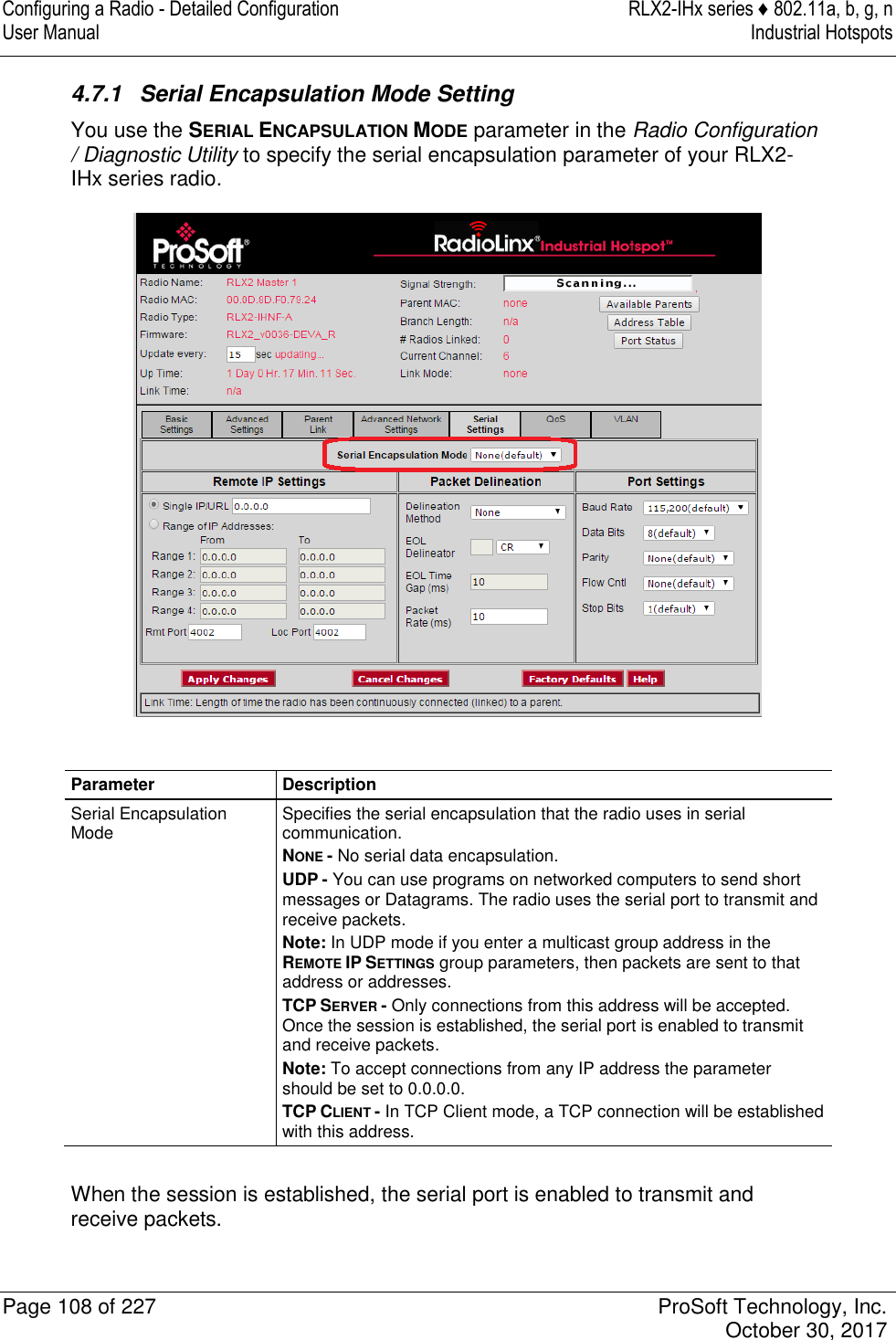
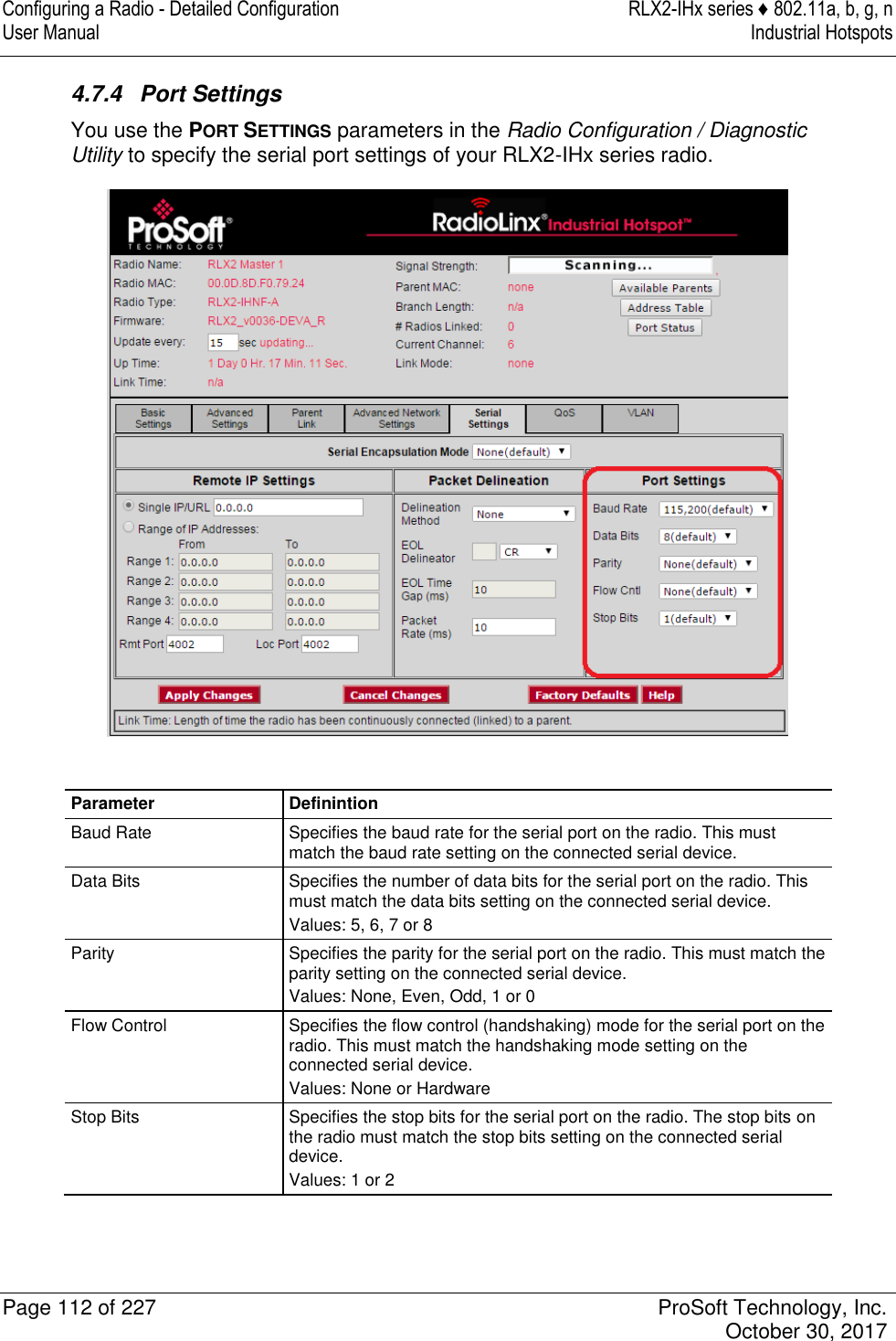
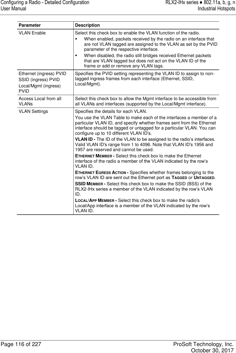
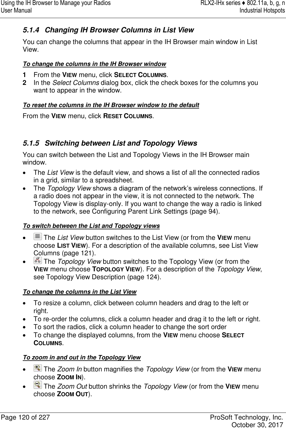
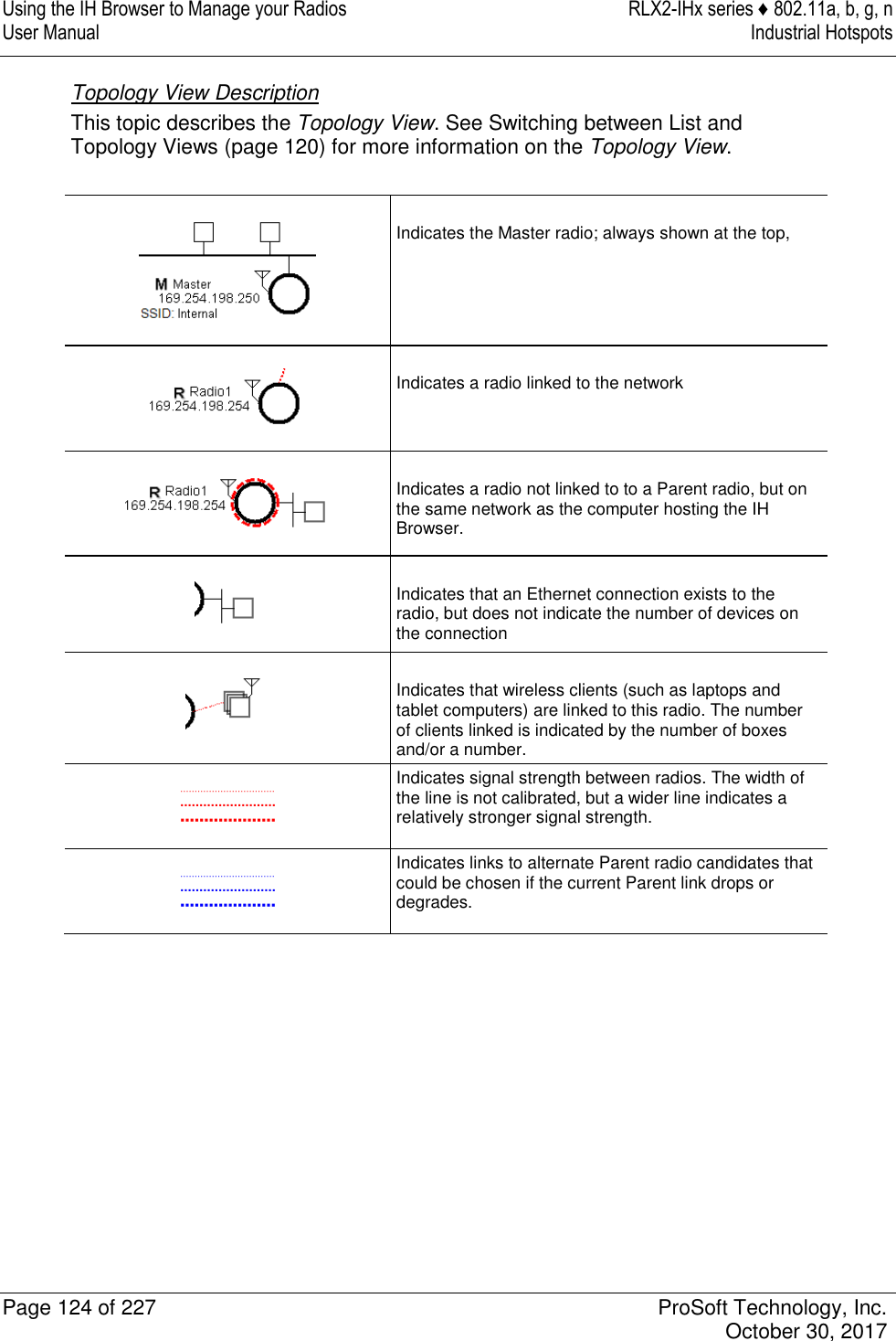
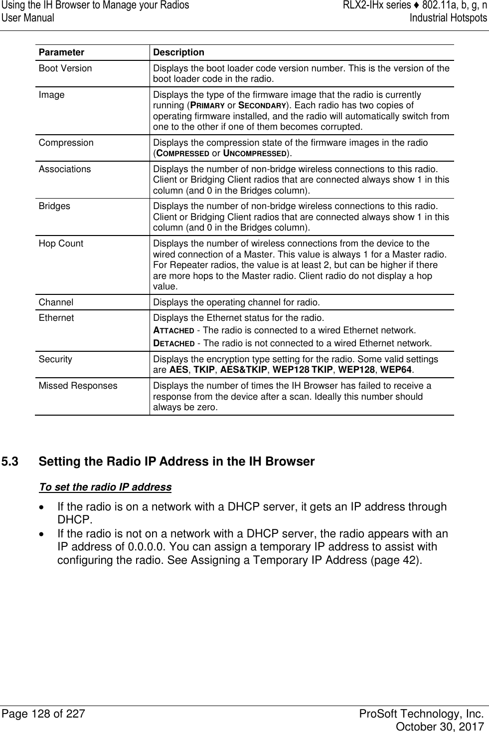
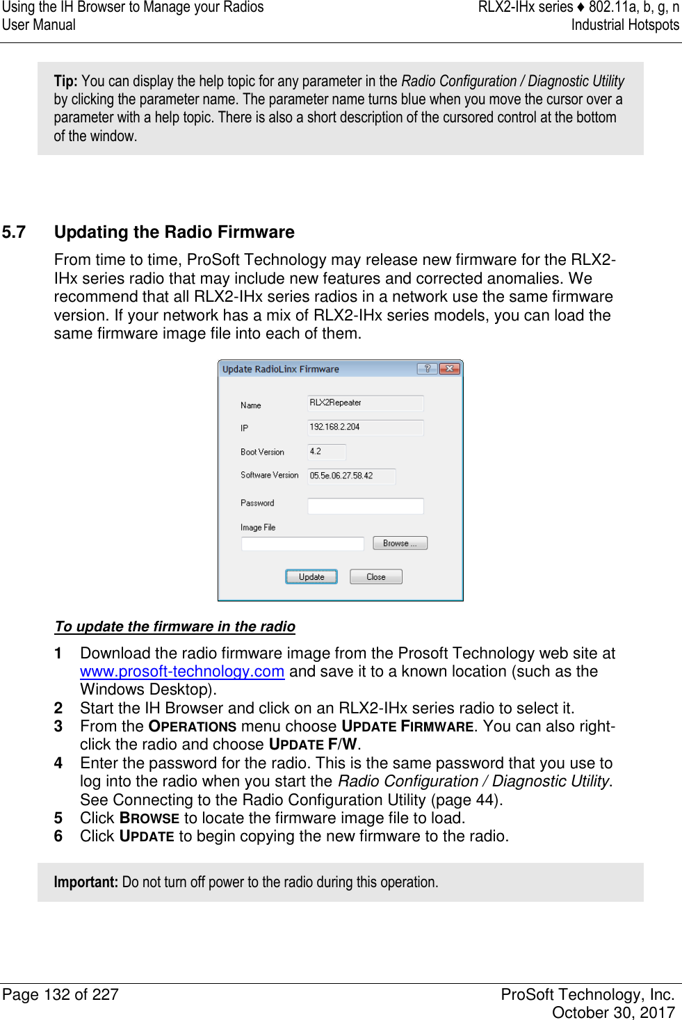
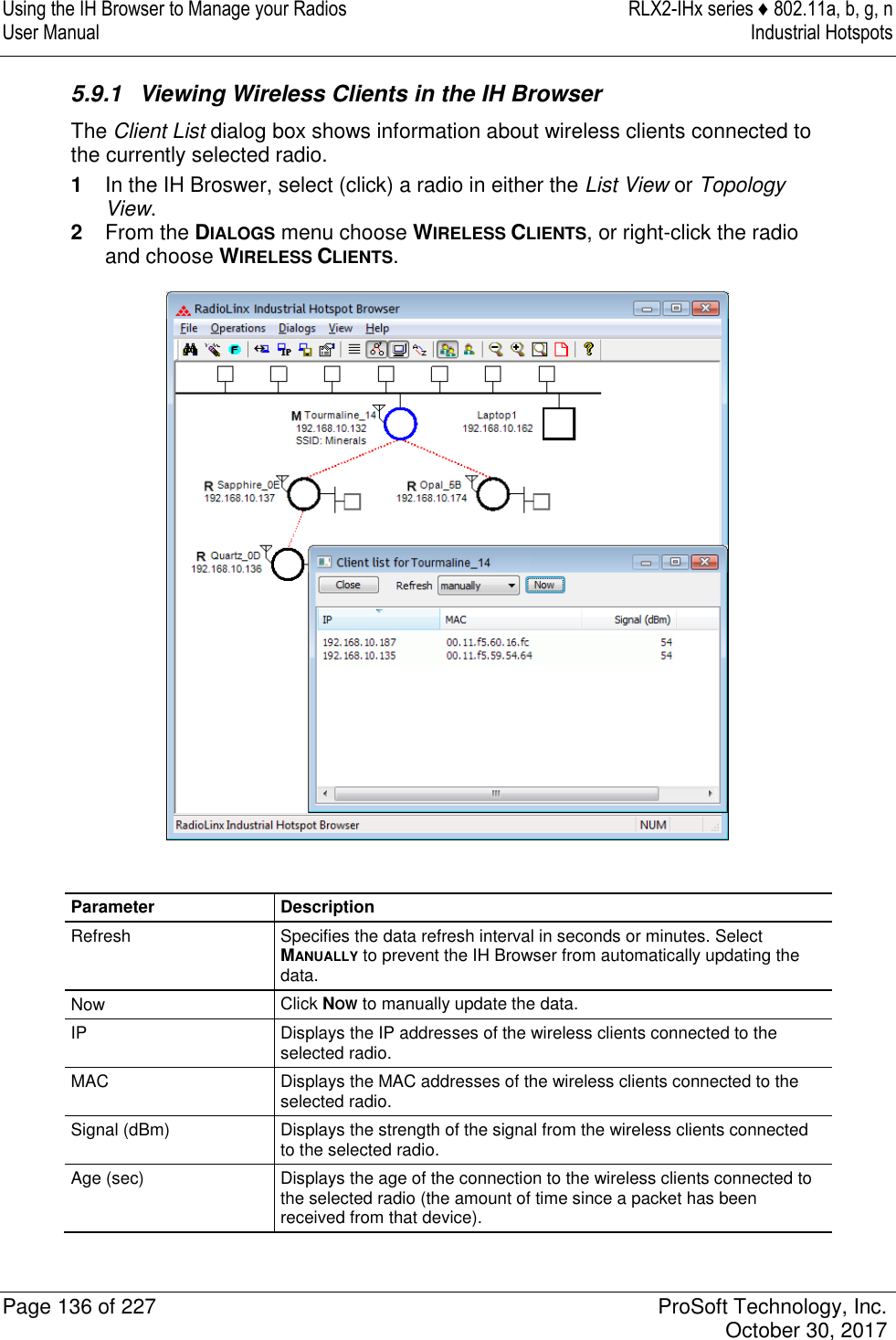
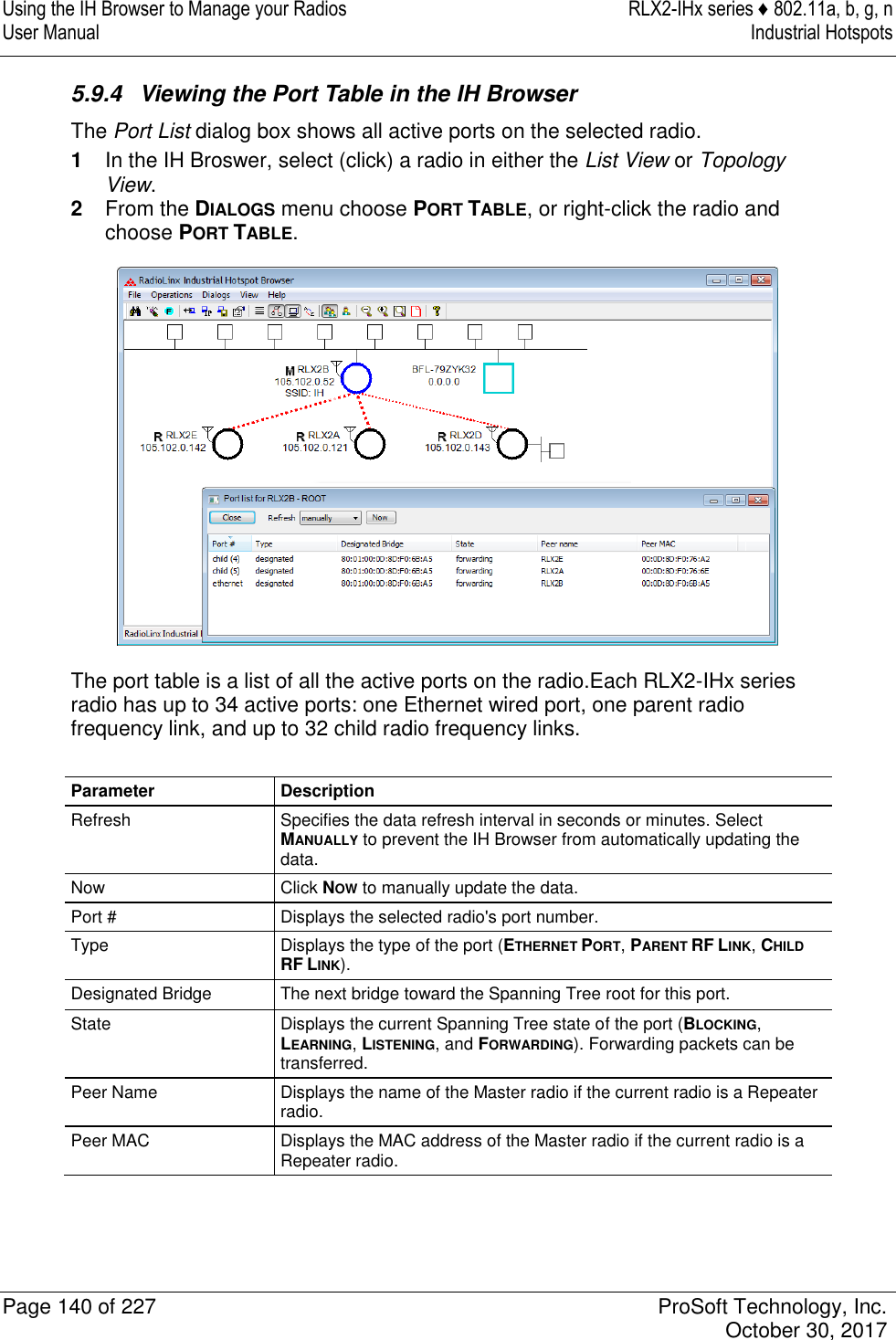
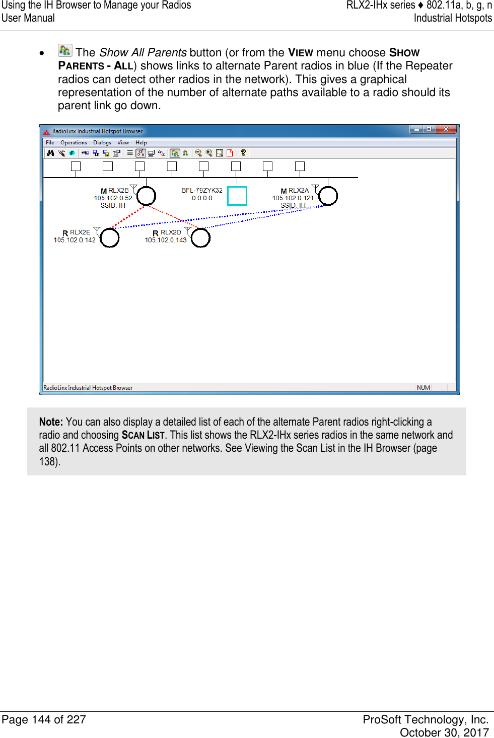
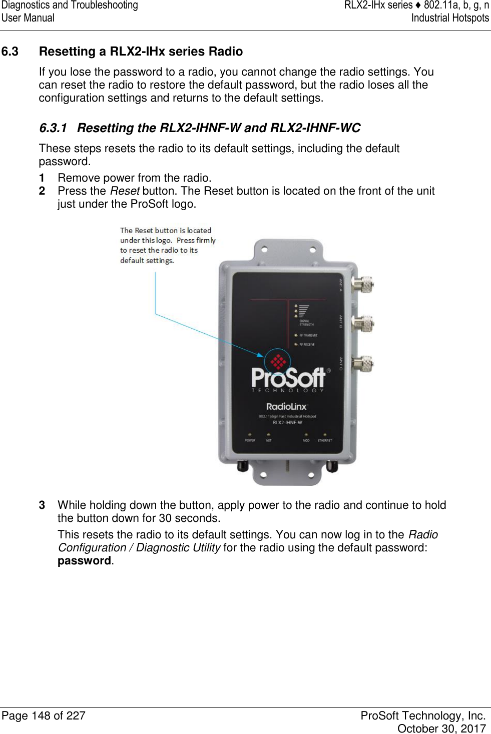
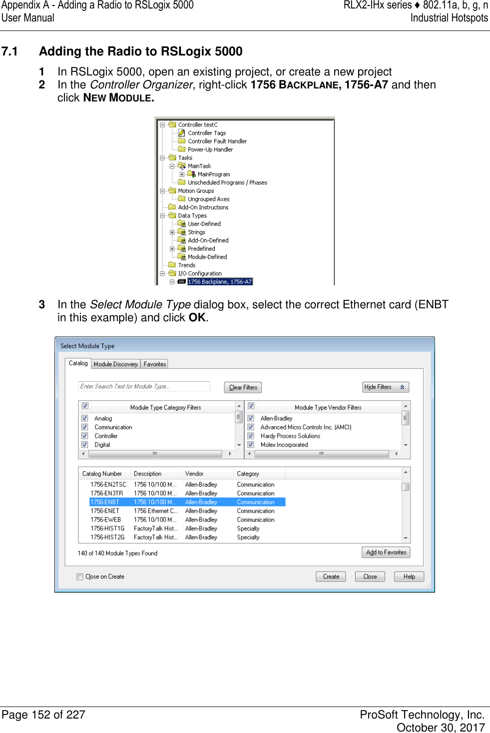

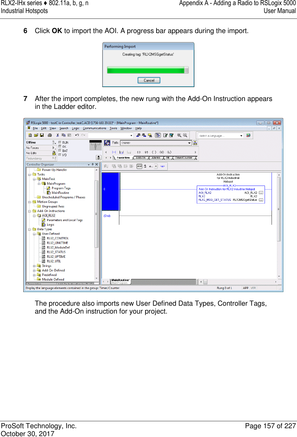
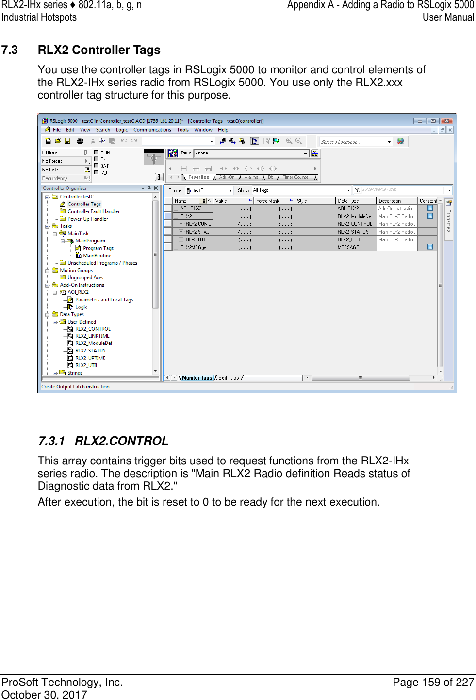
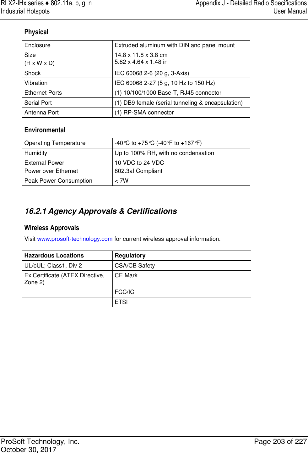
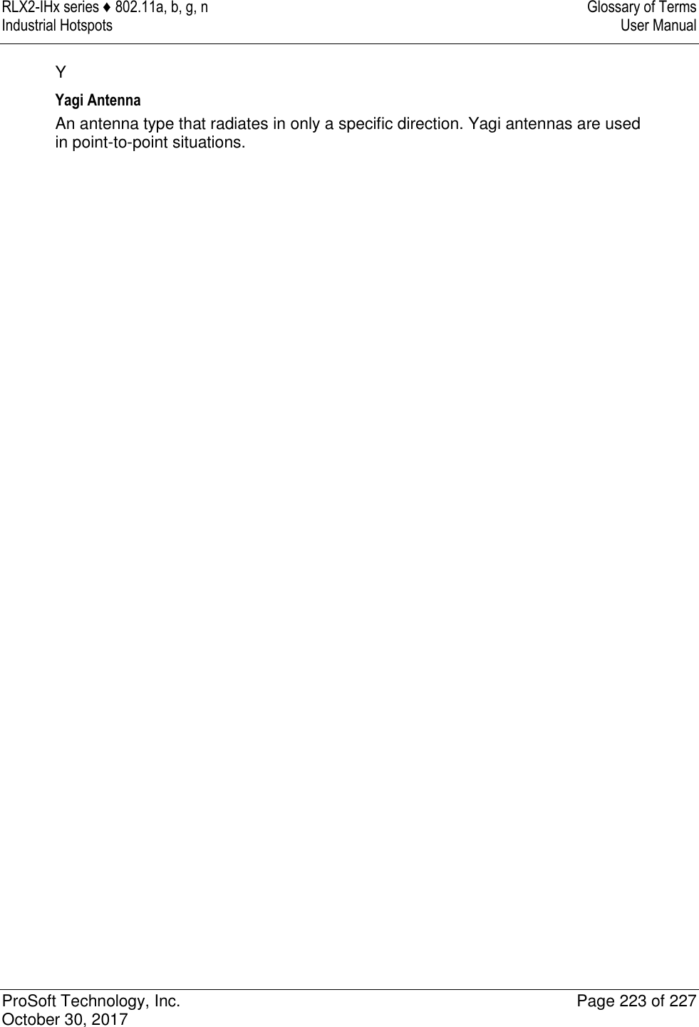
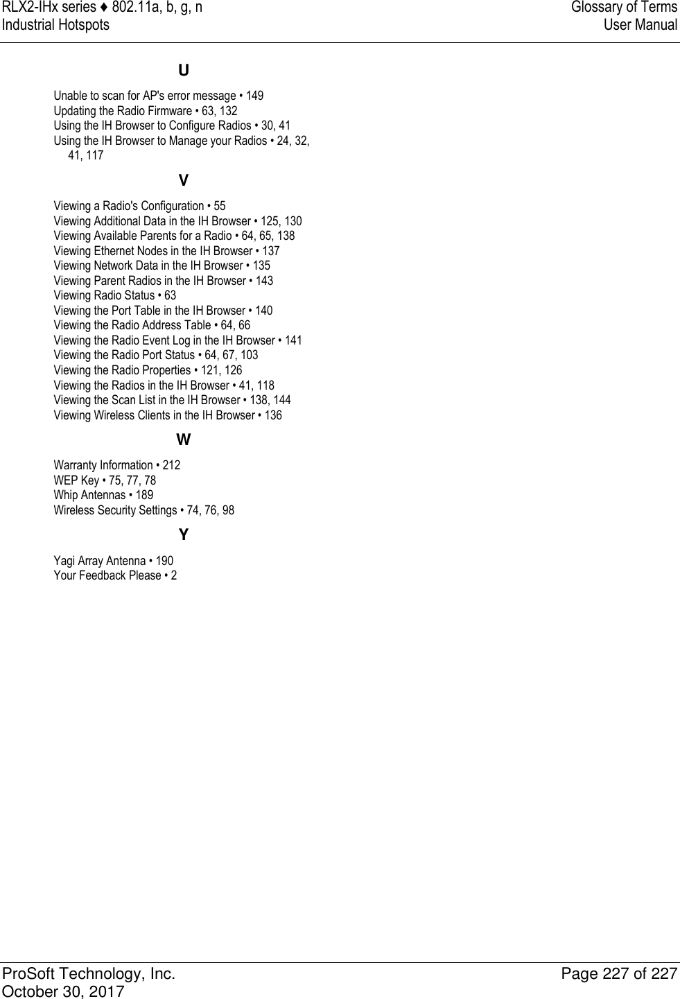
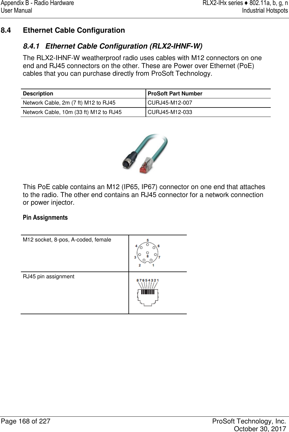
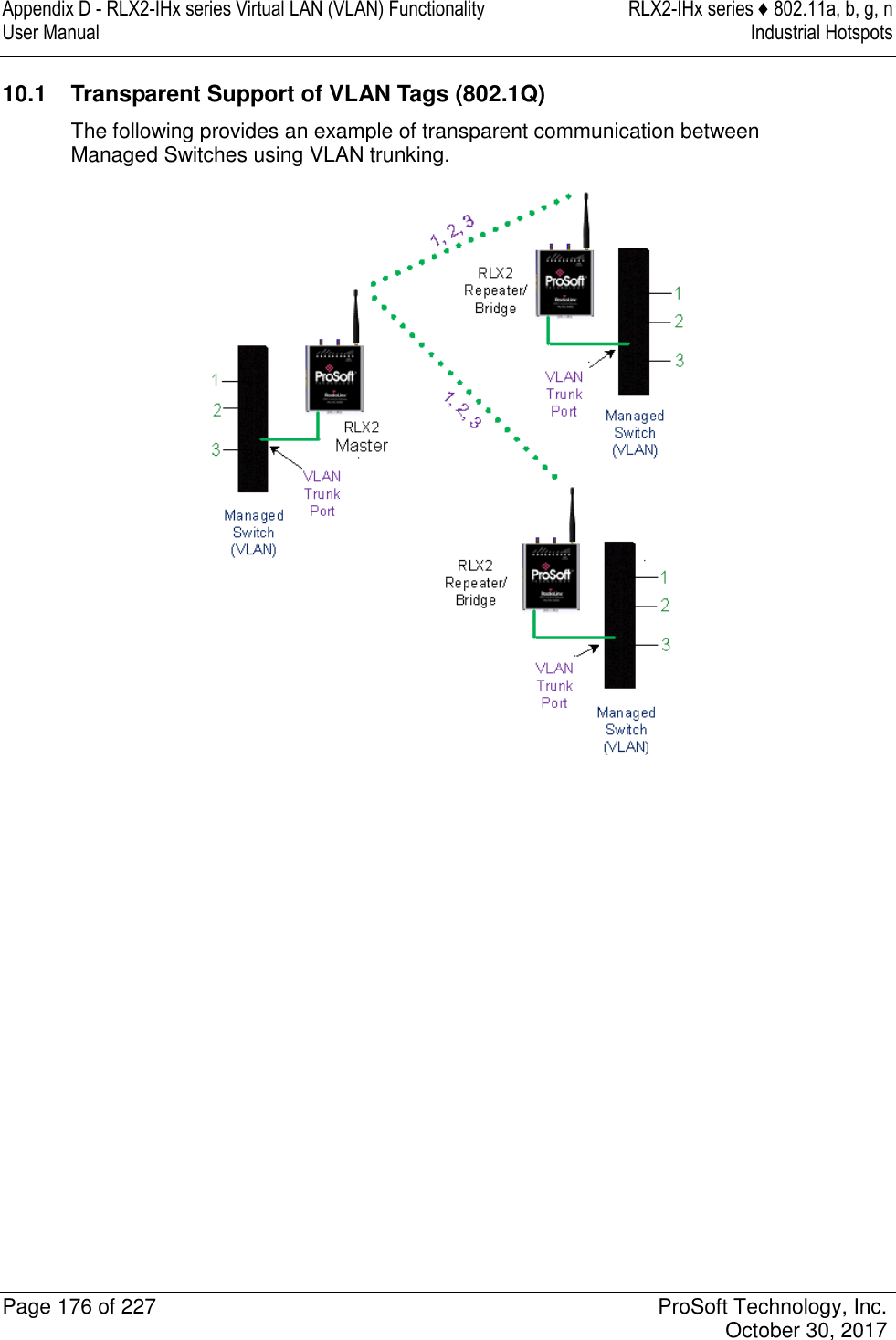
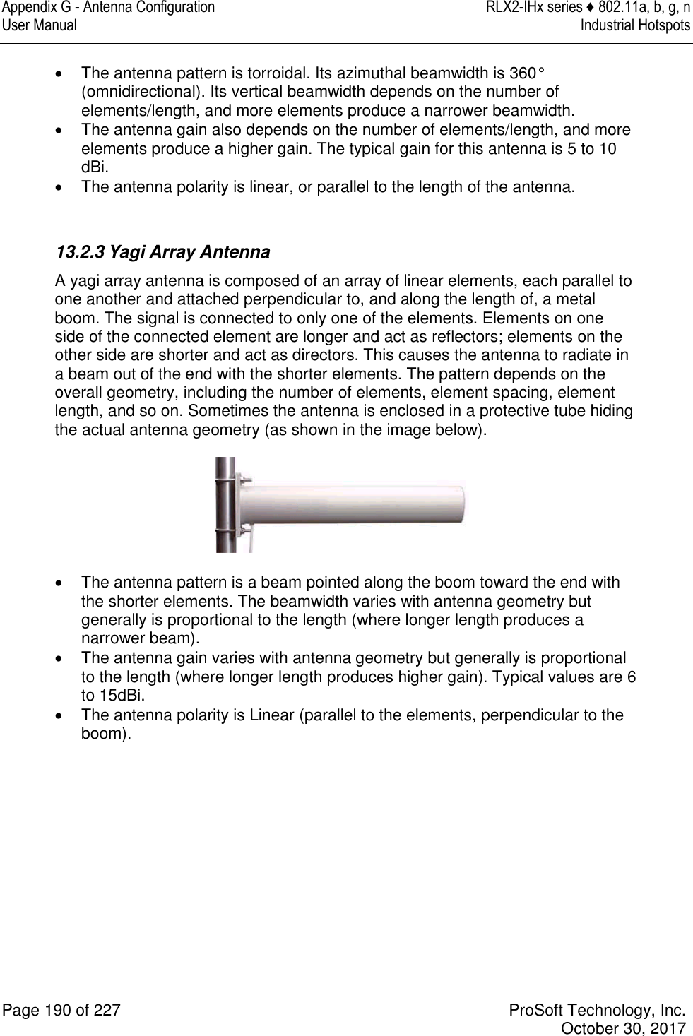
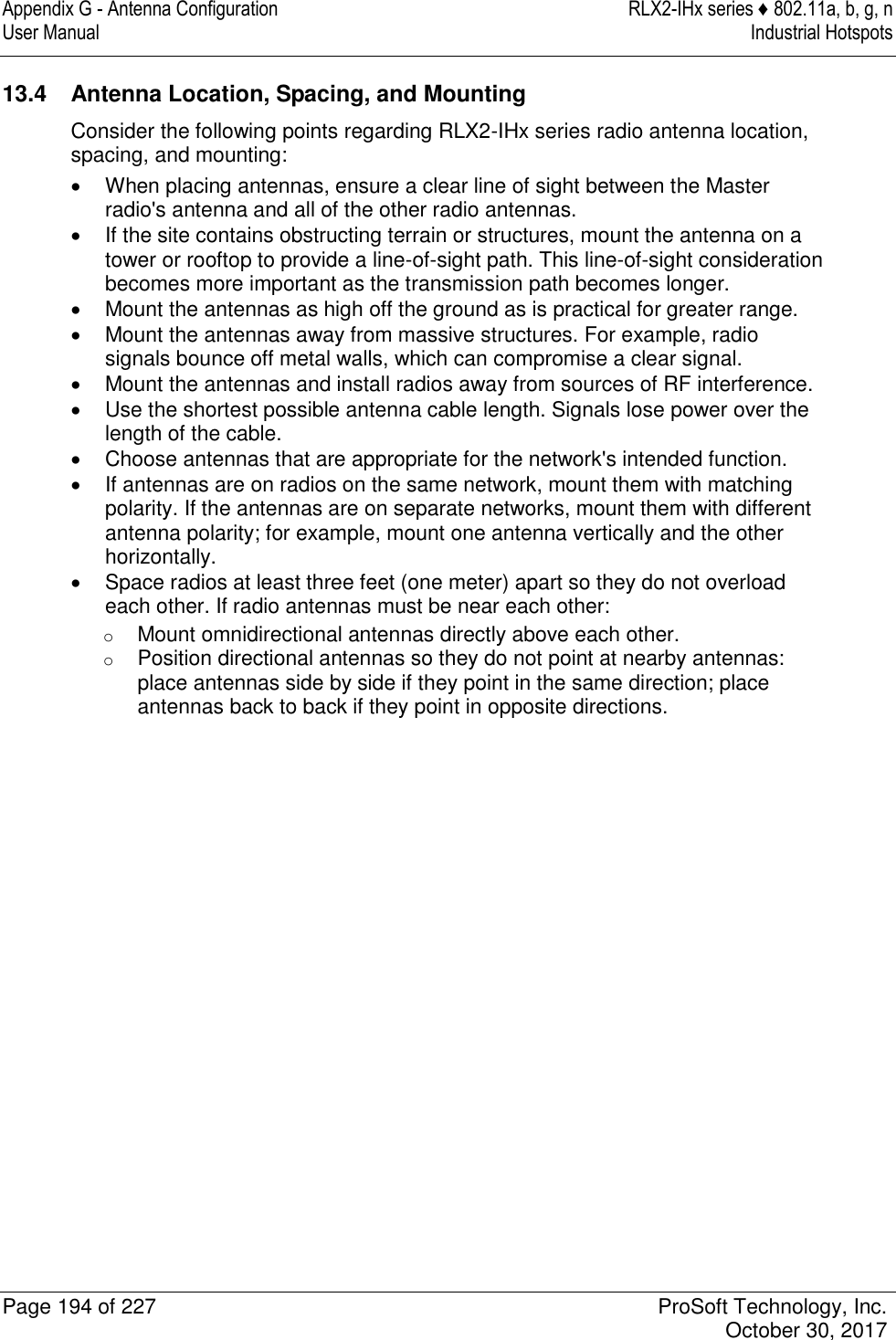
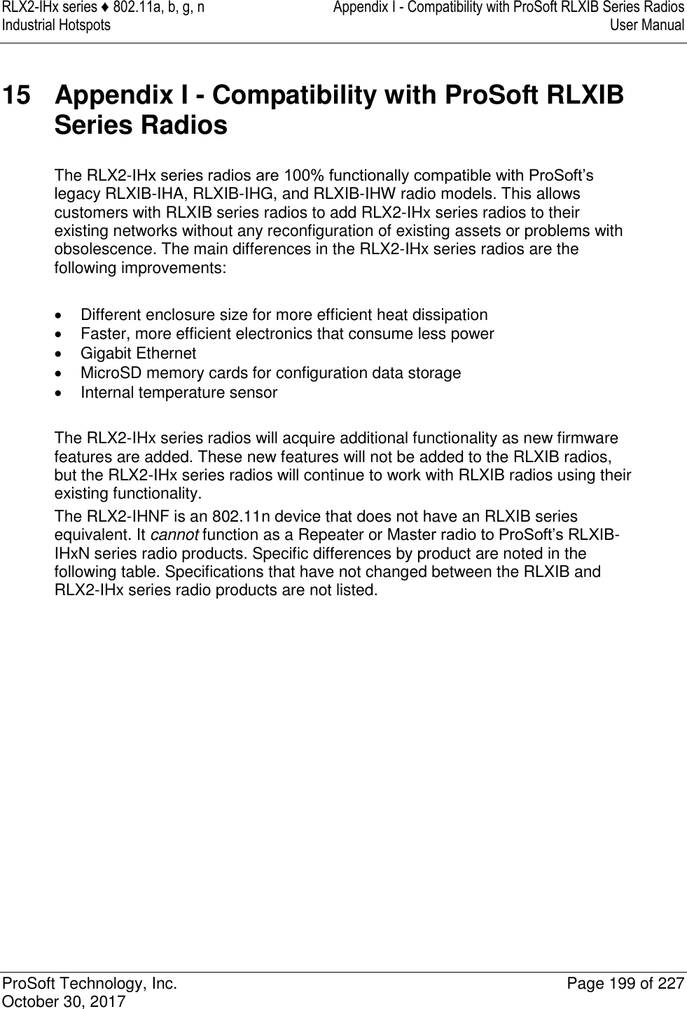
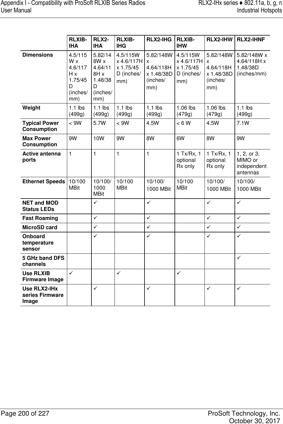
![Appendix A - Adding a Radio to RSLogix 5000 RLX2-IHx series ♦ 802.11a, b, g, n User Manual Industrial Hotspots Page 160 of 227 ProSoft Technology, Inc. October 30, 2017 7.3.2 RLX2.STATUS This array is populated when the RLX2.CONTROL.Get_Status_Data is triggered. The following is the CIP™ object definition to read the RLX2-IHx Diagnostics and Status information. CIP Data Tag Name Data Type Description RLX2.STATUS.SSID SINT[32] Service Set Identifier is a name assigned to the wireless network RLX2.STATUS.IPAddress SINT[4] IP address of RLX2-IHx radio RLX2.STATUS.MACAddress SINT[6] Physical Media Access Control (MAC) address of the device RLX2.STATUS.NetworkMode SINT RLX2 radio network mode (Master= 6 Repeater=7 Client=1) RLX2.STATUS.ConnectionState SINT Connection State of RLX2 radio found at the bit-level (RLX2.STATUS.ConnectionState.x) Bit sequence [yyyy 0001] = 1 = Not connected Bit sequence [yyyy 0010] = 2 = Scanning Not reported = 3 = Locally connected Bit sequence [yyyy 0100] = 4 = Globally connected Where y = RLX2 radio model type: Bit sequence [0001 zzzz] = 802.11g (2.4 GHz) radio Bit sequence [0010 zzzz] = 802.11a (5 GHz) radio Bit sequence [0011 zzzz] = 802.11n radio Example: Bit sequence 0010 0100 = 36 = Globally connected 5 Ghz radio RLX2.STATUS.SignalStrength INT Current Strength of the signal in dBm RLX2.STATUS.Channel SINT Current Channel in which RLX2-IHx is transmitting RLX2.STATUS.WEP SINT WEP encryption key RLX2.STATUS.Flags DINT Flags: Flag [0/1 ]= Extension channel Flag [2] = SSIDhidden Flag [3] = Allow Children Flag [4/5] = STP/RSTP Flag [6] = TXusingGI RLX2.STATUS.MasterMACAddress SINT[6] MAC Address of Parent Radio in which Repeater or Client is linked RLX2.STATUS.HopCount SINT Number of hops to the master RLX2.STATUS.PortStatus SINT Ethernet Port Status 1 = 10 Mb/s 2 = 100 Mb/s 3 = 1000 Mb/s RLX2.STATUS.Associations INT Number of network elements to which radio has wireless connection RLX2.STATUS.BridgeAssociations INT Number of devices to which radio has wireless connection](https://usermanual.wiki/ProSoft-Technology/IHNFC/User-Guide-3673268-Page-60.png)
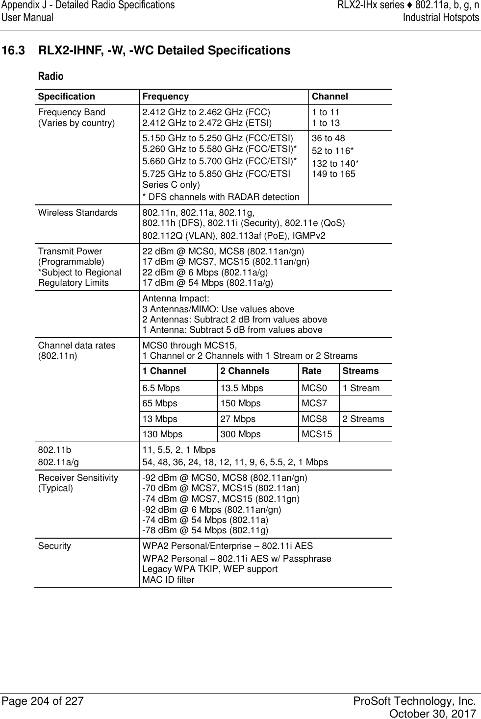
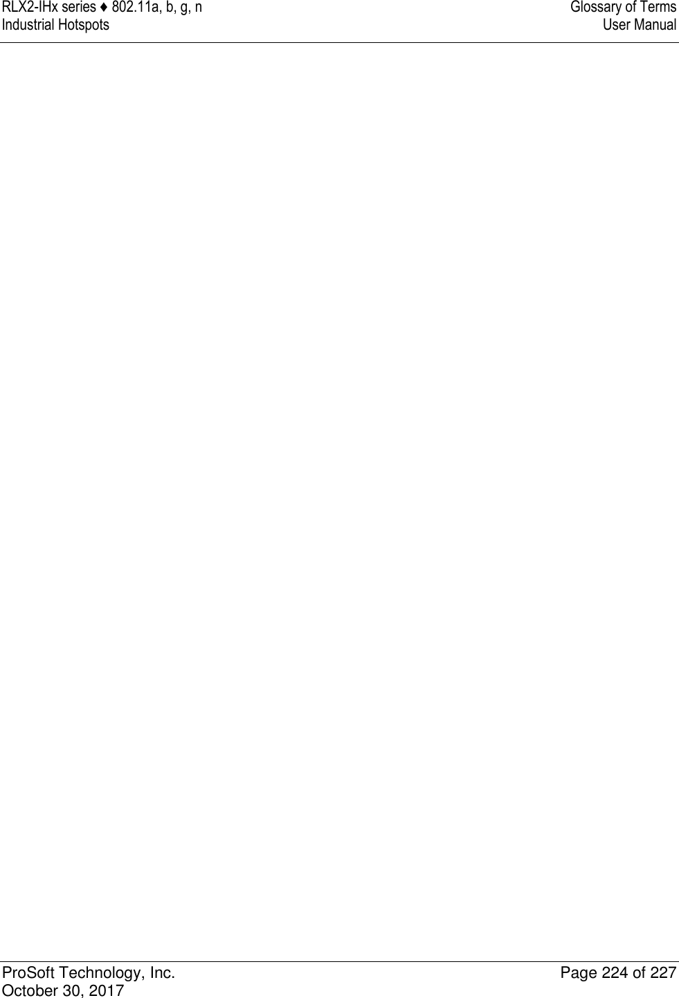
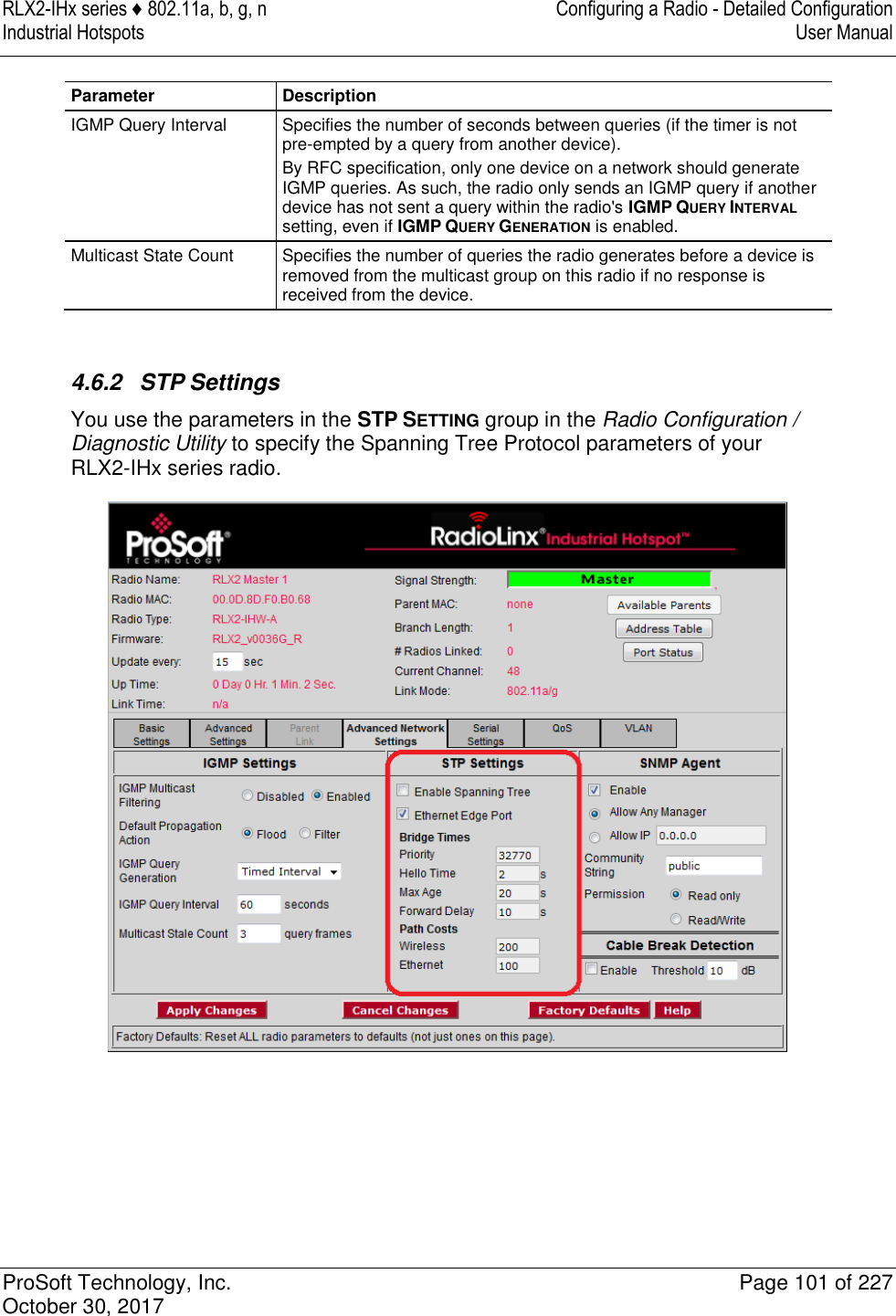
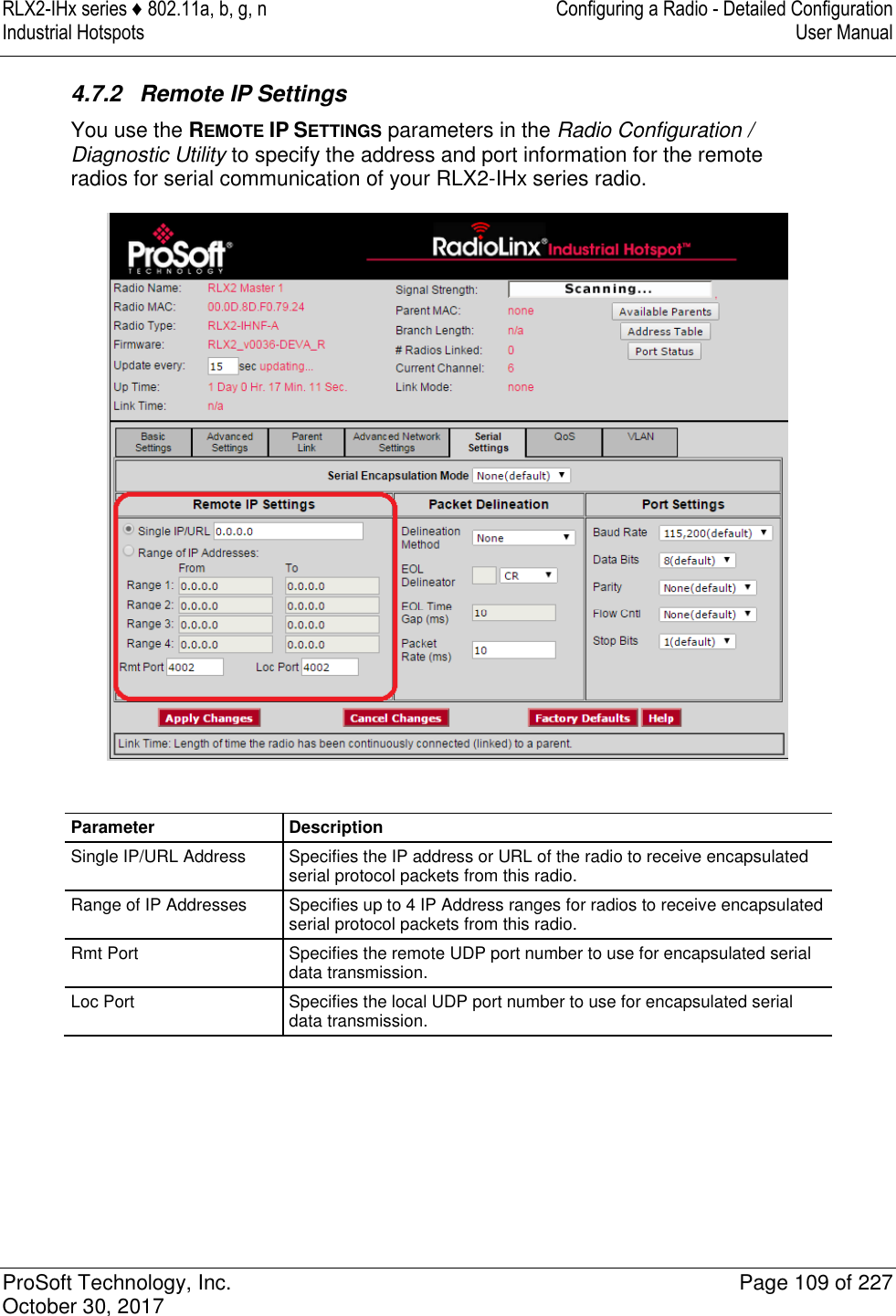
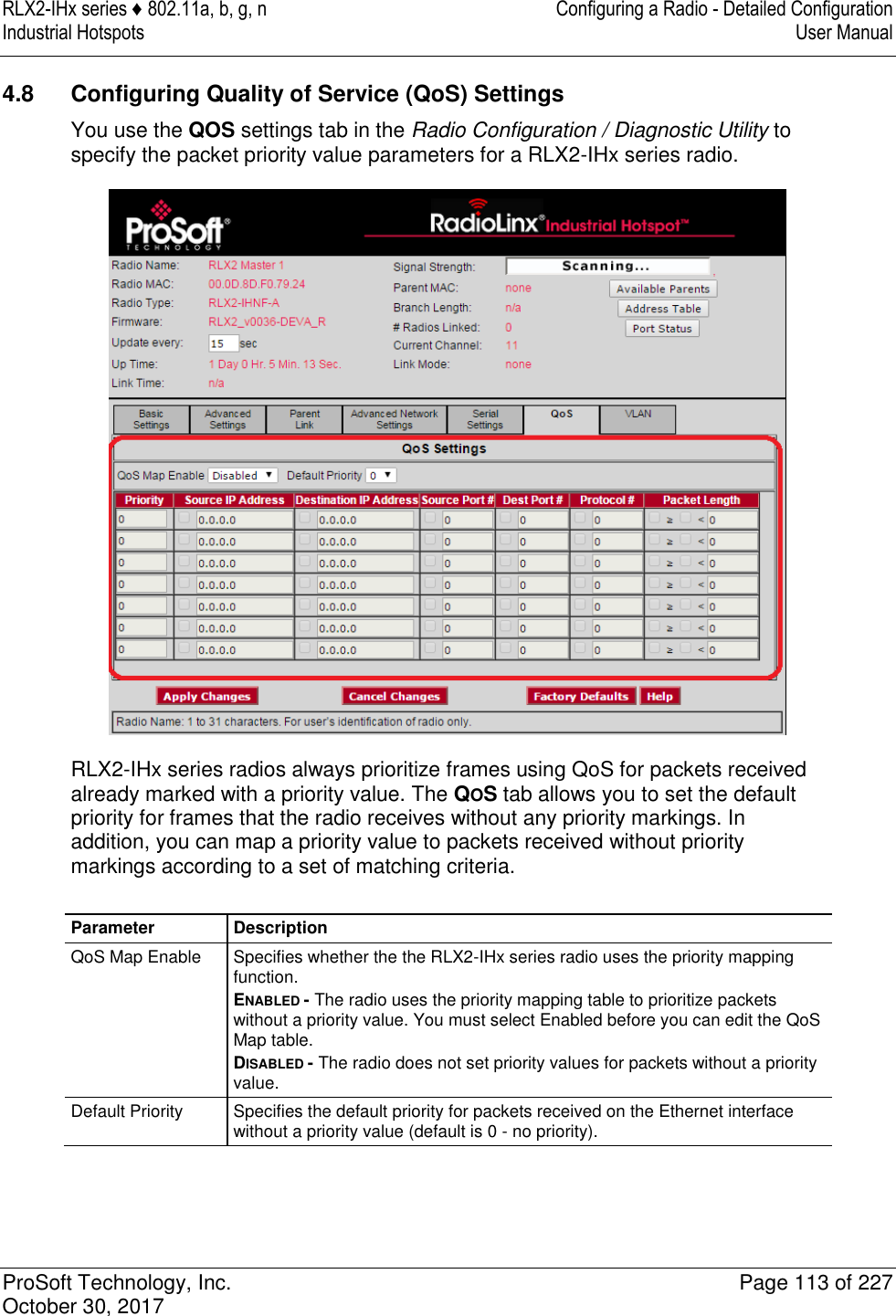
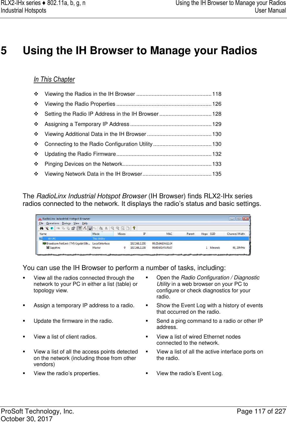
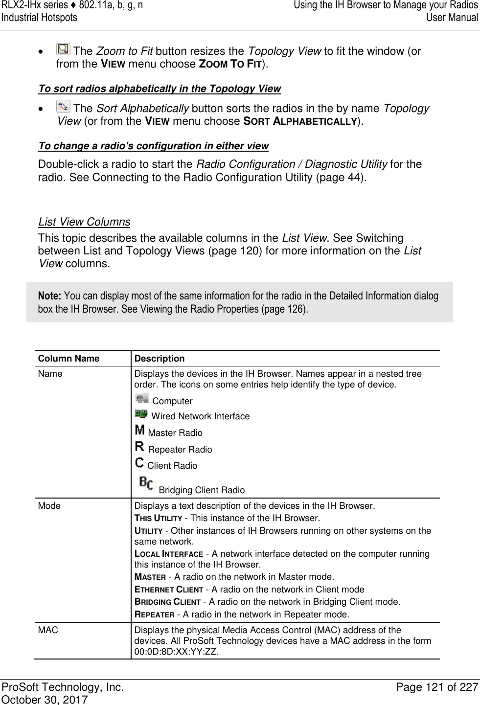
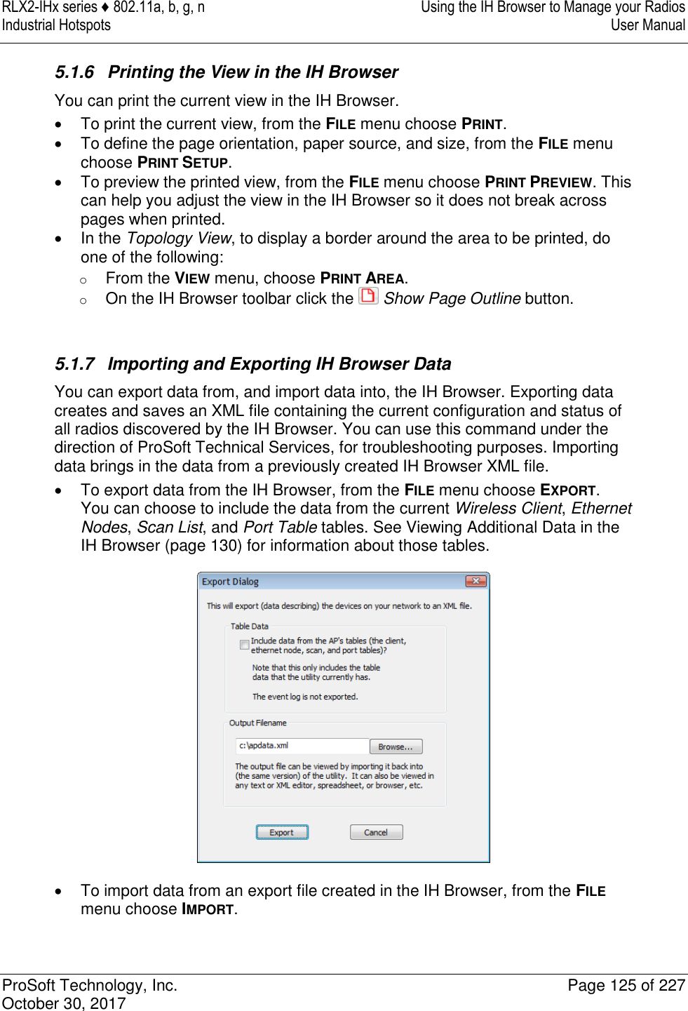
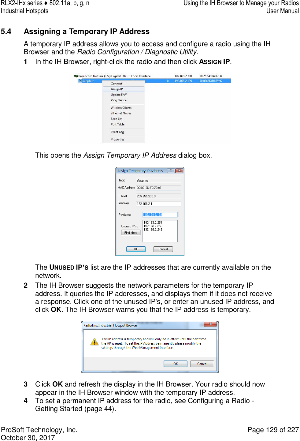
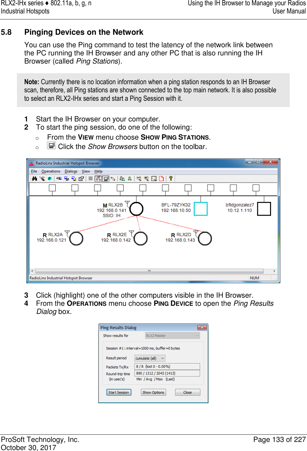
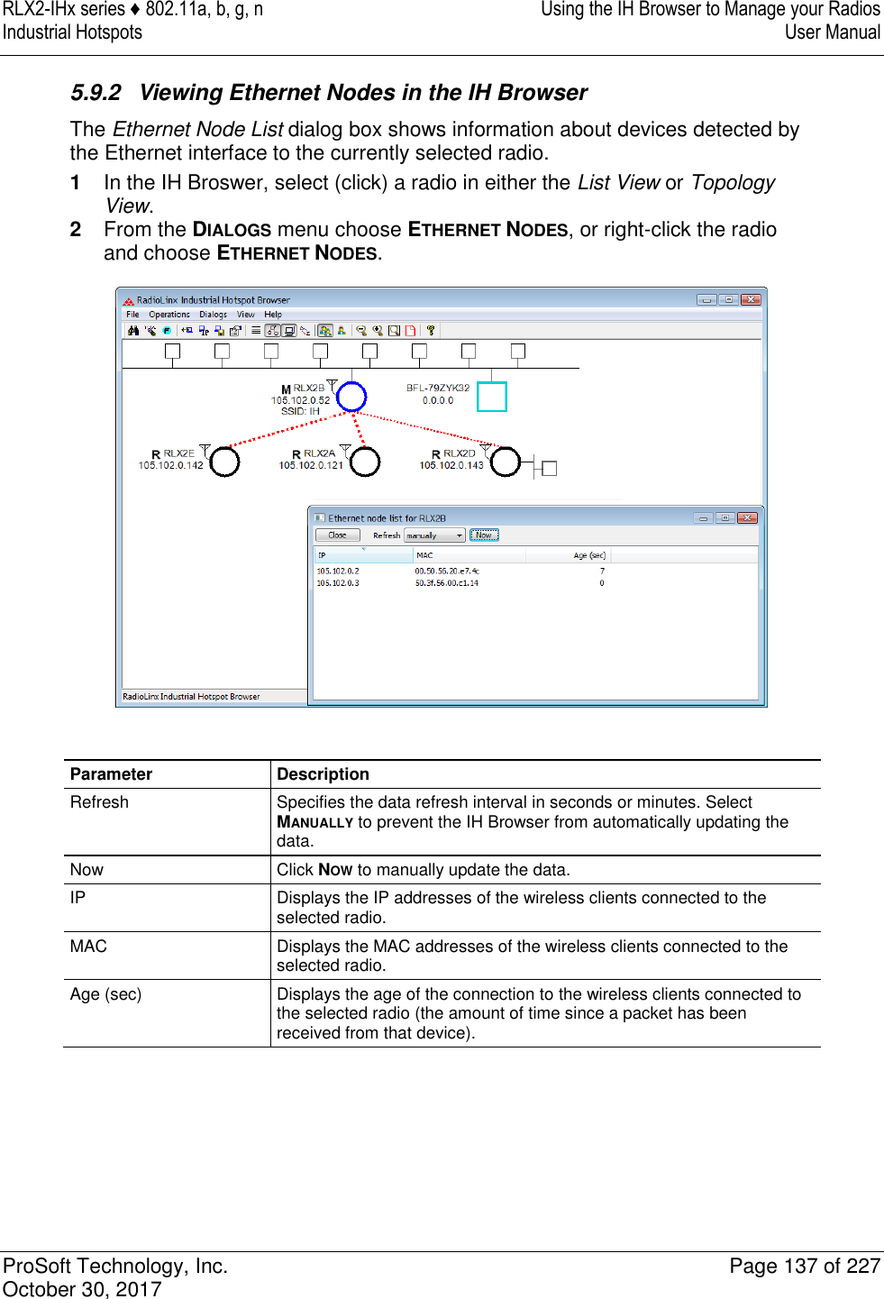
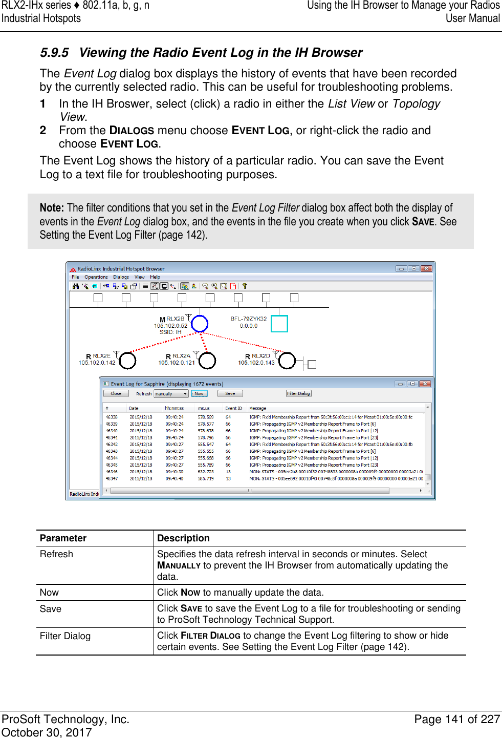
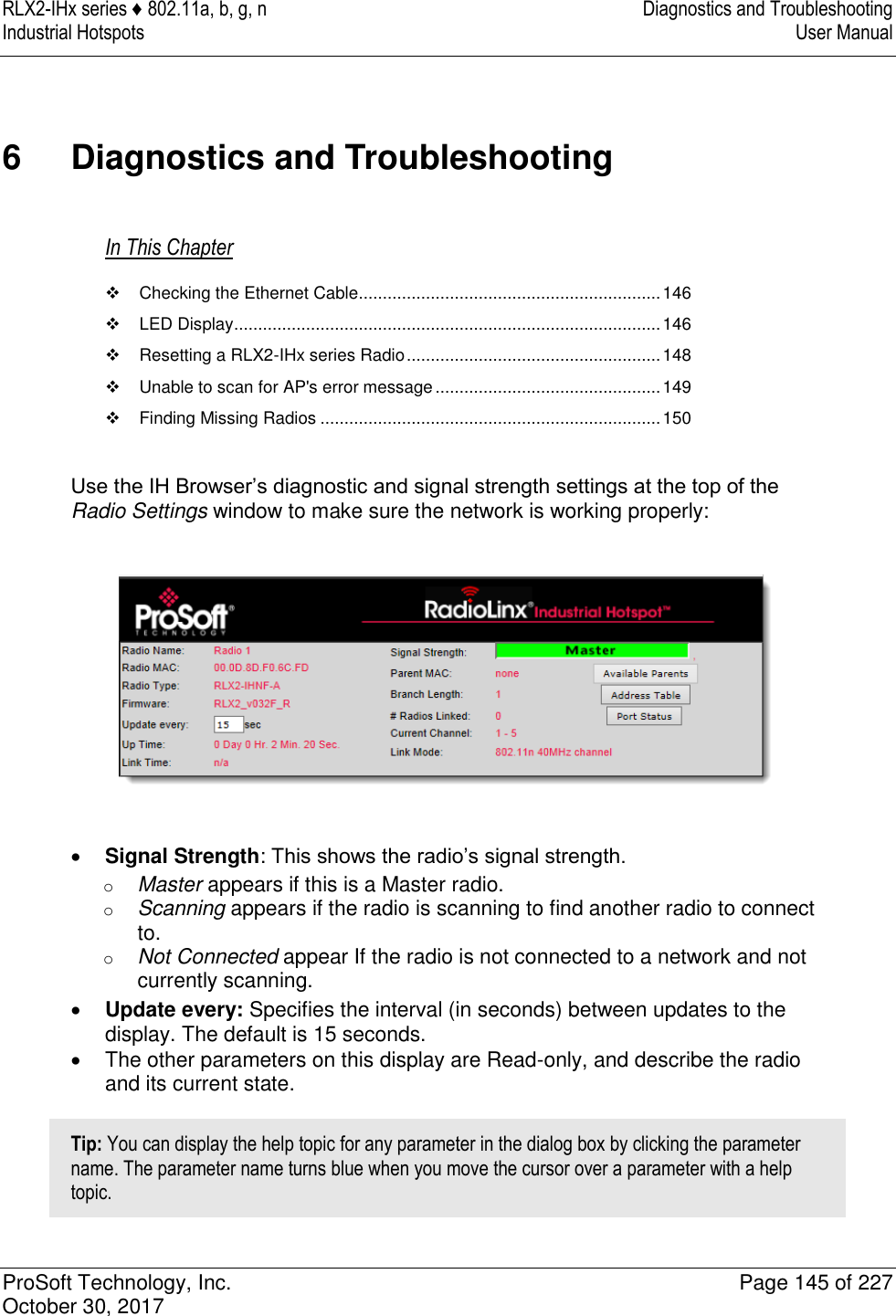
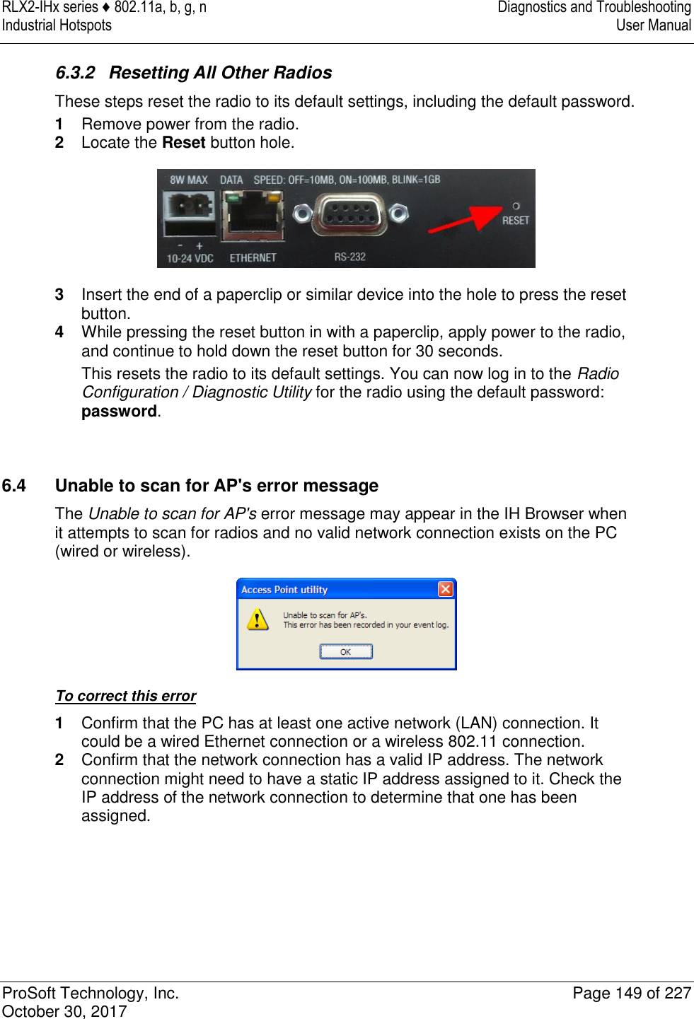
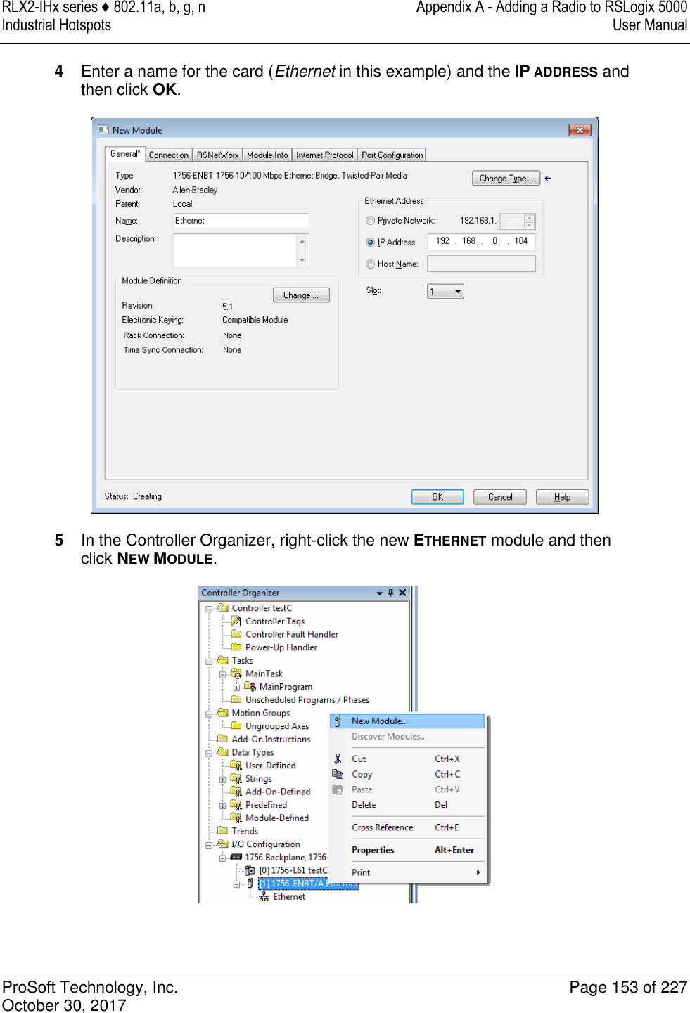
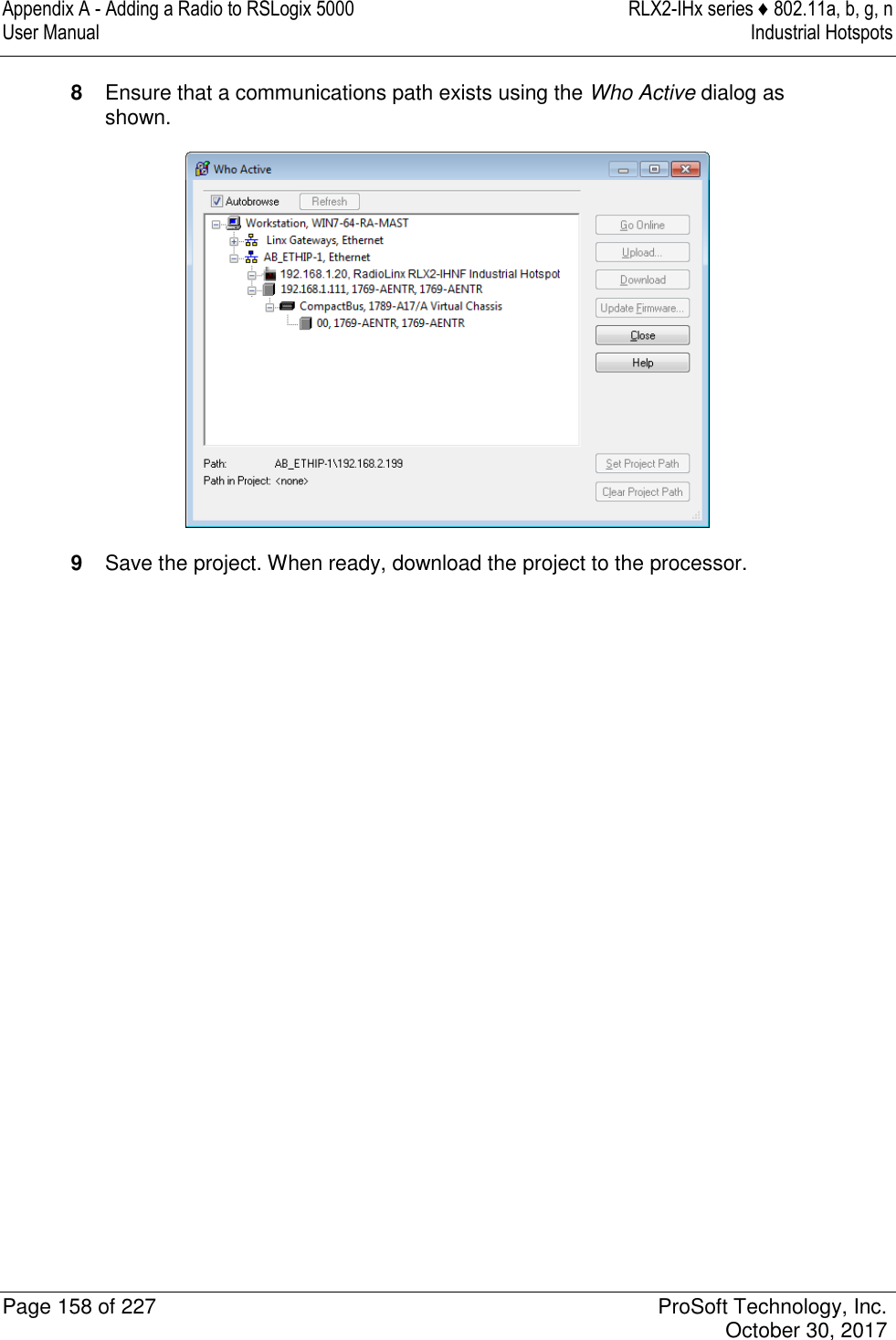
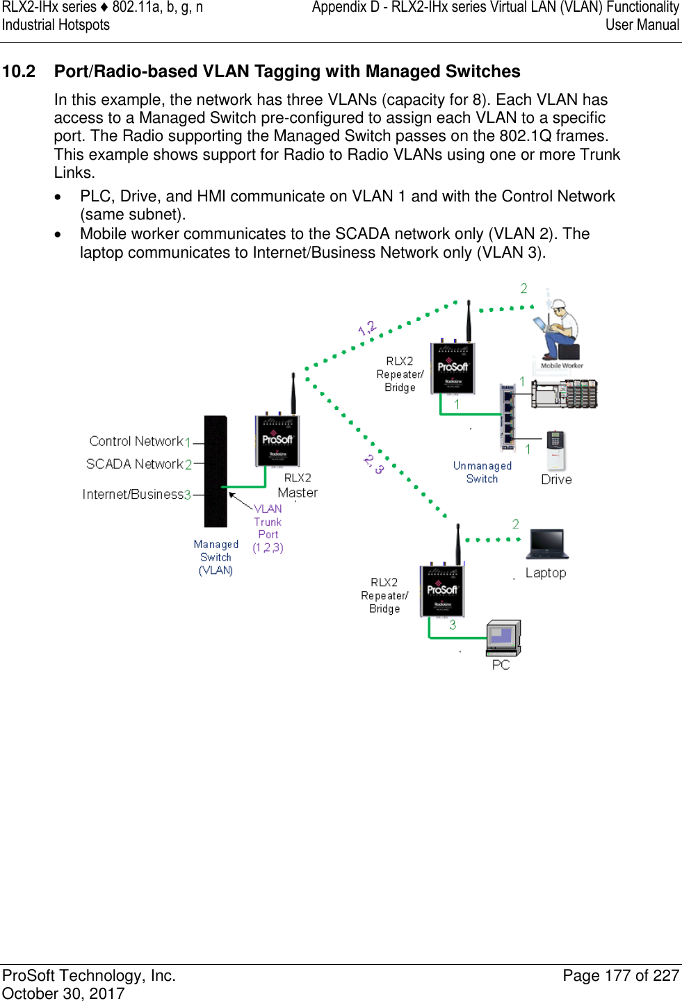
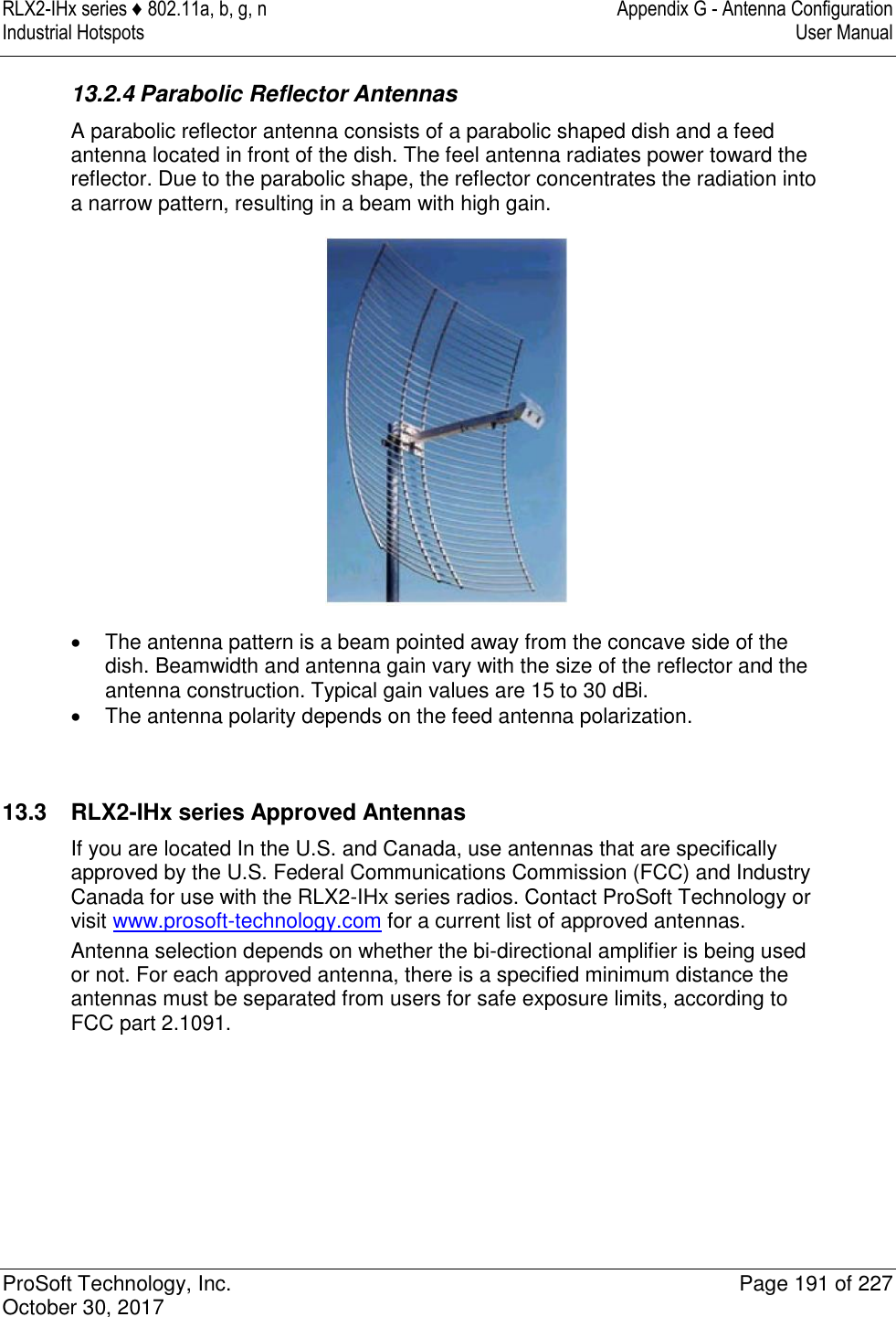
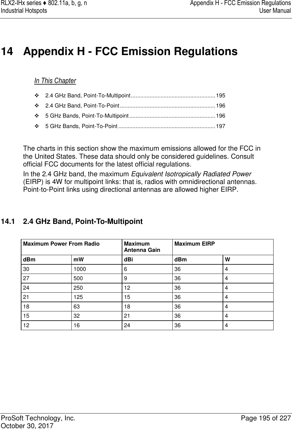
![RLX2-IHx series ♦ 802.11a, b, g, n Appendix A - Adding a Radio to RSLogix 5000 Industrial Hotspots User Manual ProSoft Technology, Inc. Page 161 of 227 October 30, 2017 RLX2.STATUS.TxRadioThroughput INT Transmit throughput in kilobits per second RLX2.STATUS.RxRadioThroughput INT Receive throughput in kilobits per second RLX2.STATUS.Uptime INT This is the amount of time the radio has been running since power up (Days/Hours/Minutes/Seconds) RLX2.STATUS.Linktime DINT The time the radio has been linked (Days/Hours/Minutes/Seconds) RLX2.STATUS.TxPacketRate DINT Total number of packets transmitted RLX2.STATUS.RxPacketRate DINT Total number of packets received RLX2.STATUS.ModuleName DINT The name of the radio RLX2.STATUS.ProductName SINT[32] Name of product RLX2.STATUS.ImageVerStr SINT[32] Firmware version loaded in device RLX2.STATUS.TxGood SINT[28] Number of Good Transmitted Frames RLX2.STATUS.RxGood DINT Number of Good Received Frames RLX2.STATUS.TxBad DINT Number of Bad Transmitted Frames RLX2.STATUS.RxBad DINT Number of Bad Received Frames RLX2.STATUS.TxDirectedFrames DINT Number of Transmitted Directed Frames RLX2.STATUS.TxMulticastFrames DINT Number of Transmitted Multicast Frames RLX2.STATUS.TxBroadcastFrames DINT Number of Transmitted Broadcast Frames RLX2.STATUS.RxDirectedFrames DINT Number of Received Directed Frames RLX2.STATUS.RxMulticastFrames DINT Number of Received Multicast Frames RLX2.STATUS.RxBroadcastFrames DINT Number of Transmitted Broadcast Frames RLX2.STATUS.RxCRCErr DINT Number of CRC Errors](https://usermanual.wiki/ProSoft-Technology/IHNFC/User-Guide-3673268-Page-61.png)
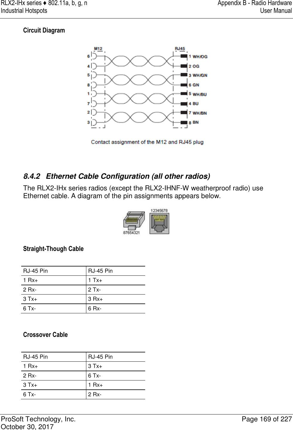
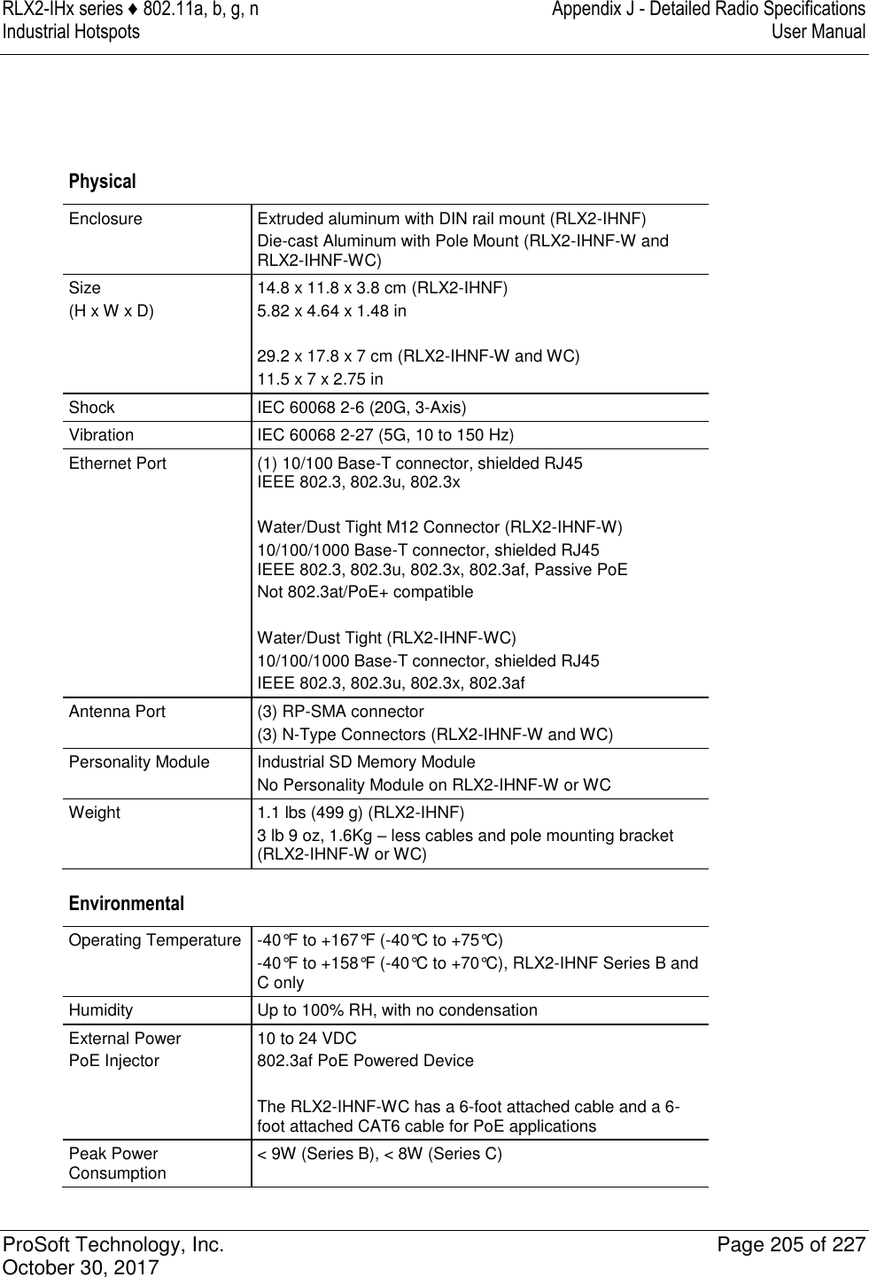
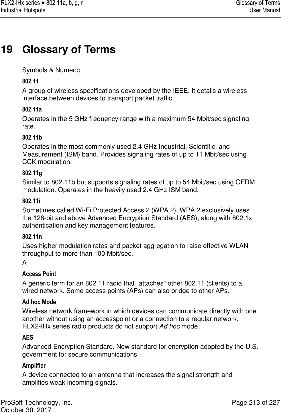
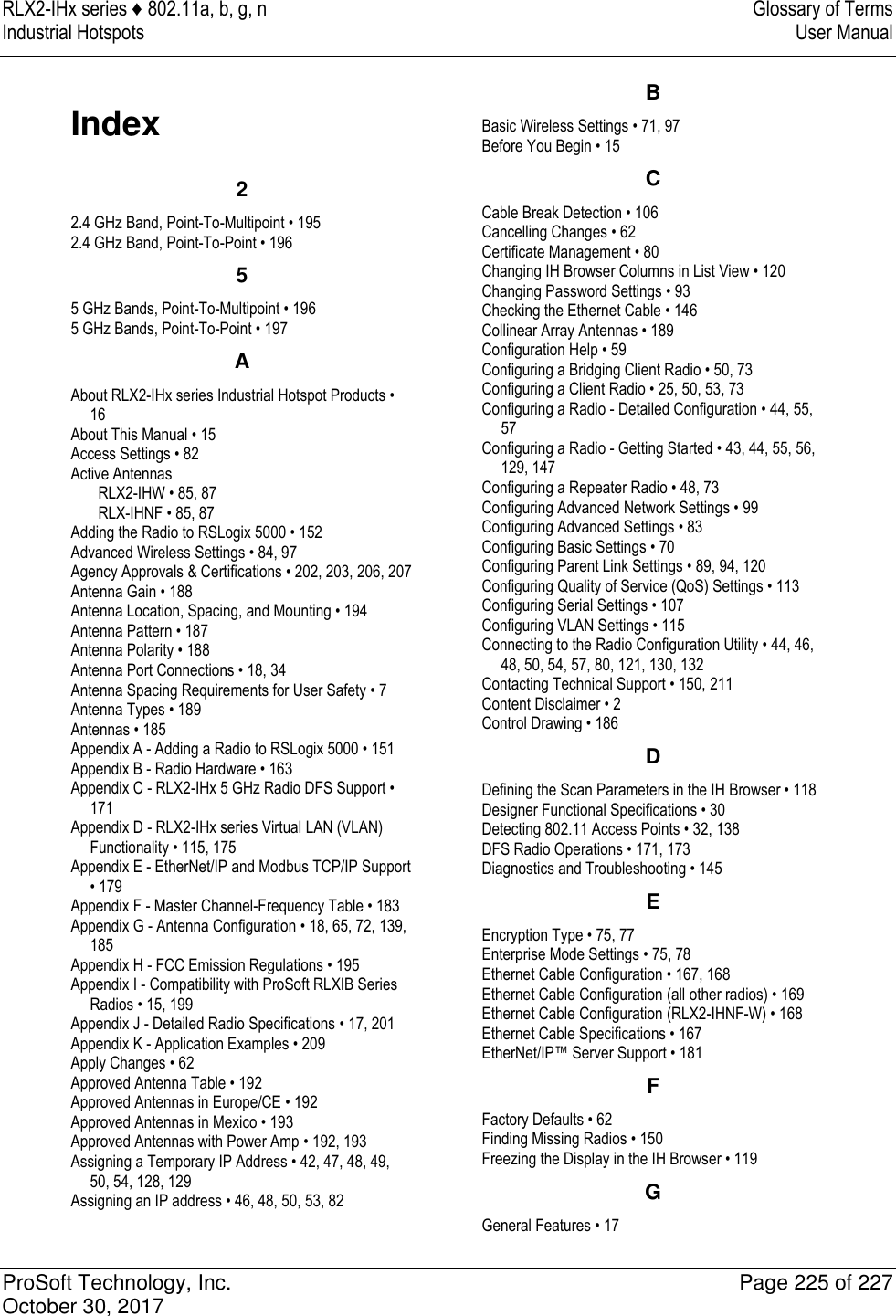
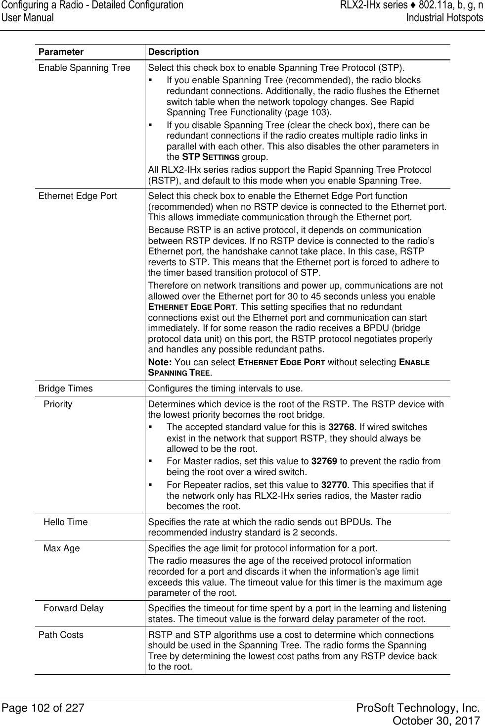
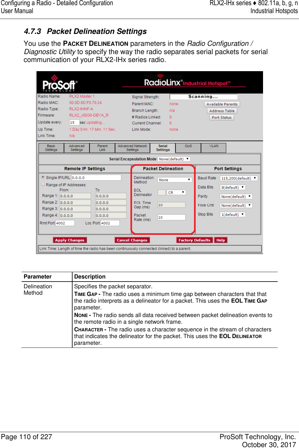
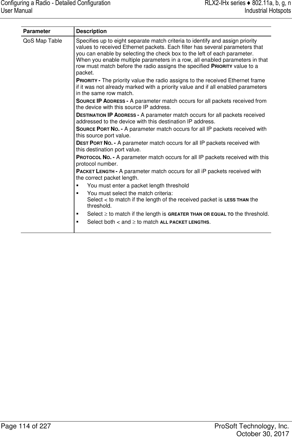
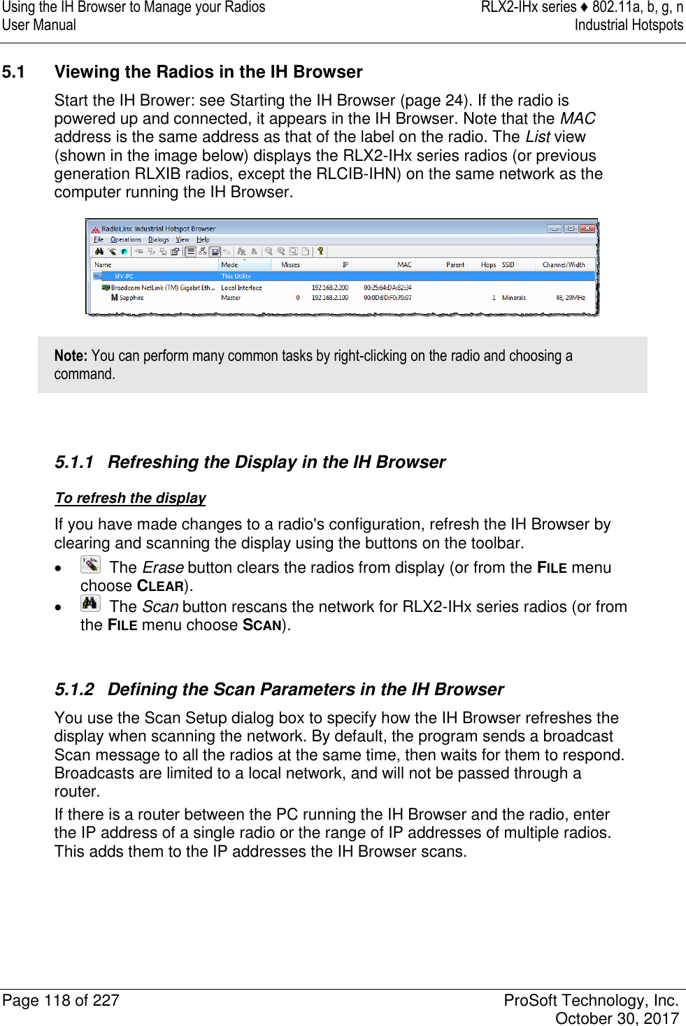
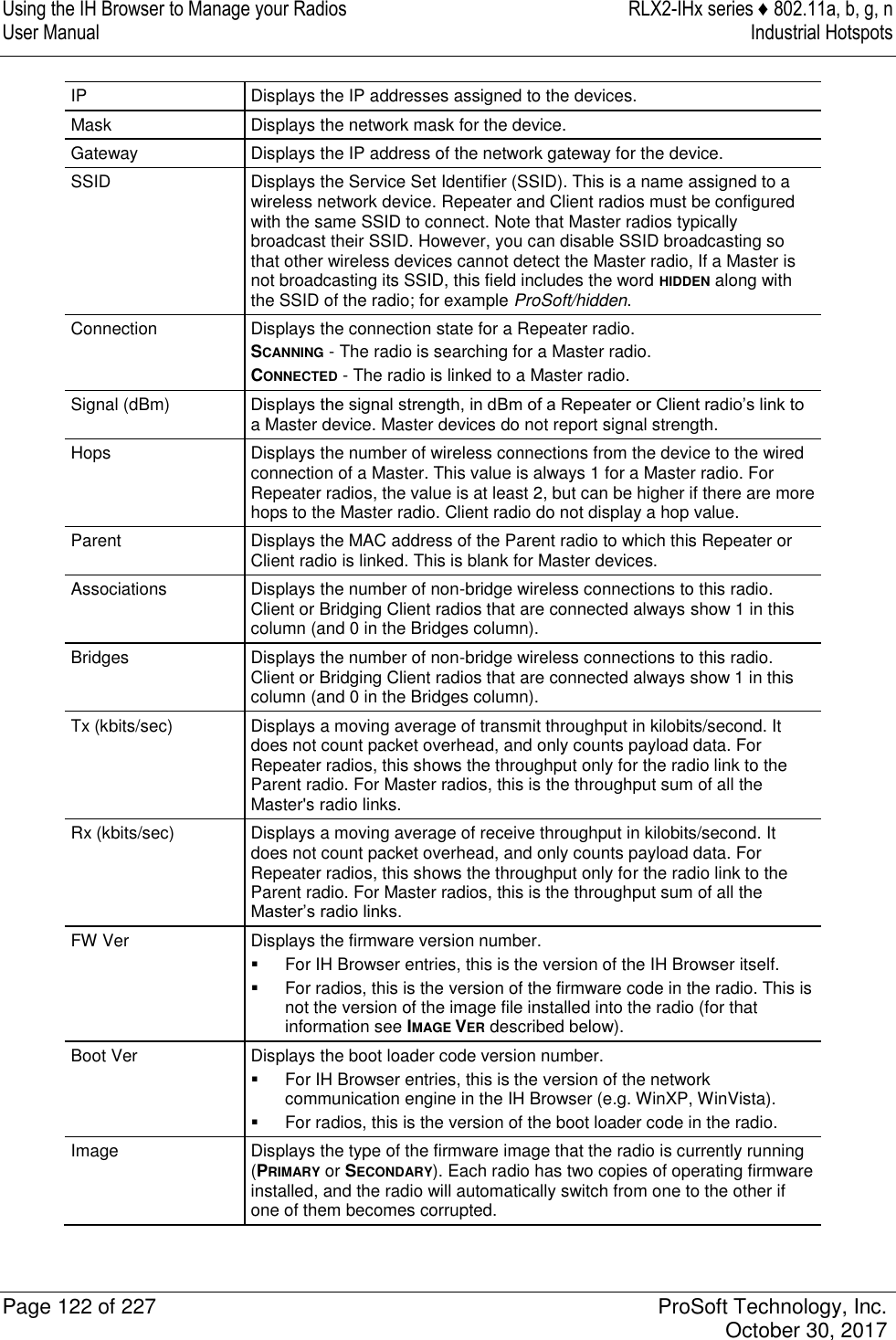
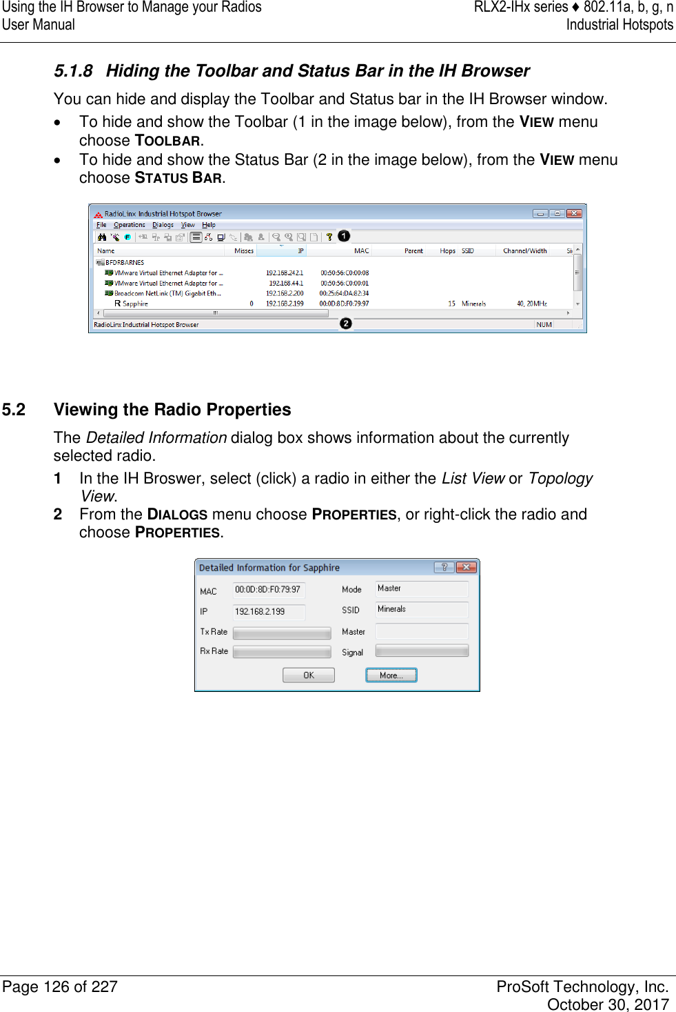
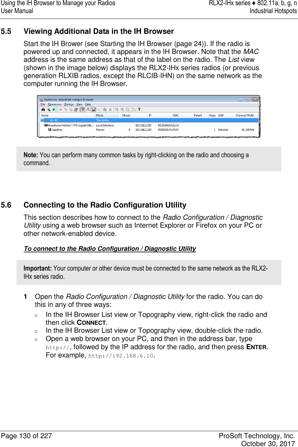
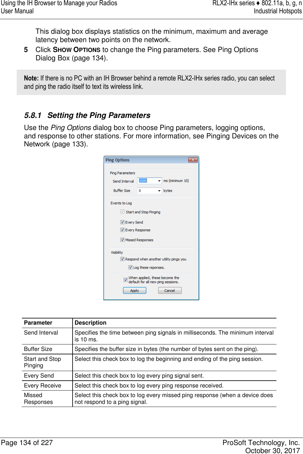
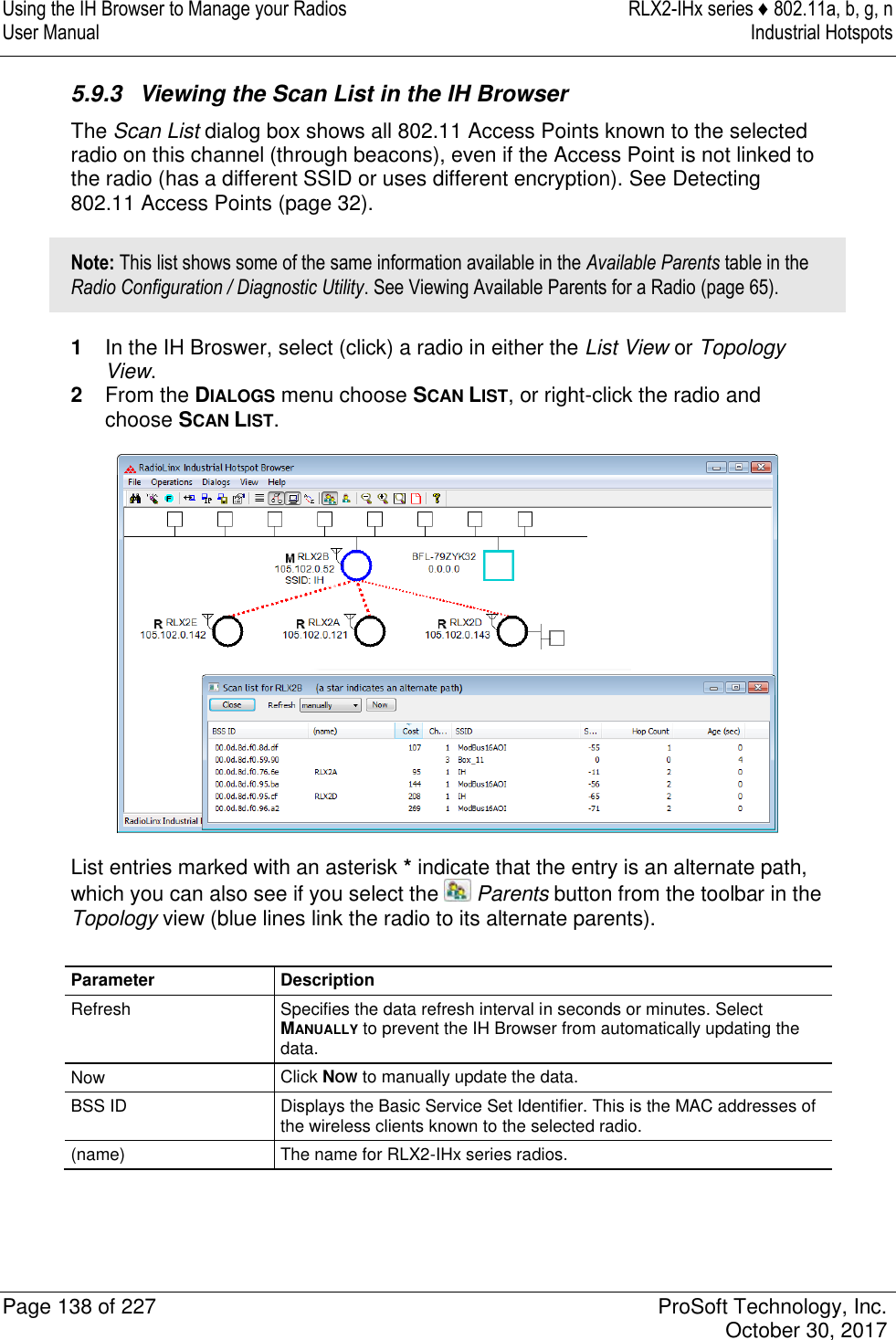
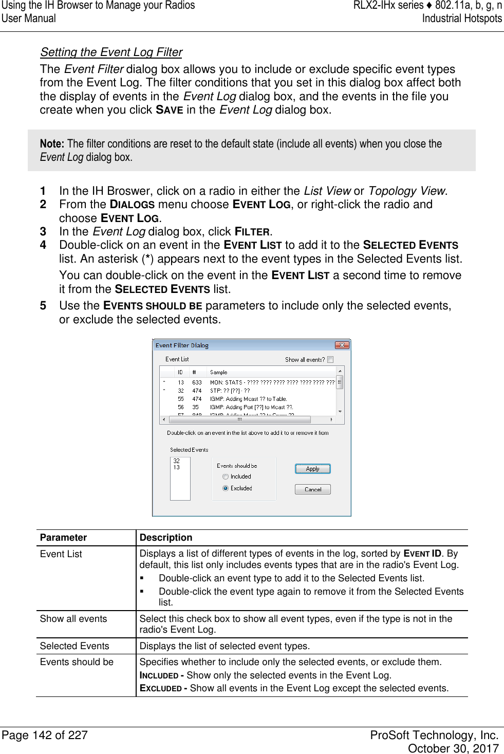
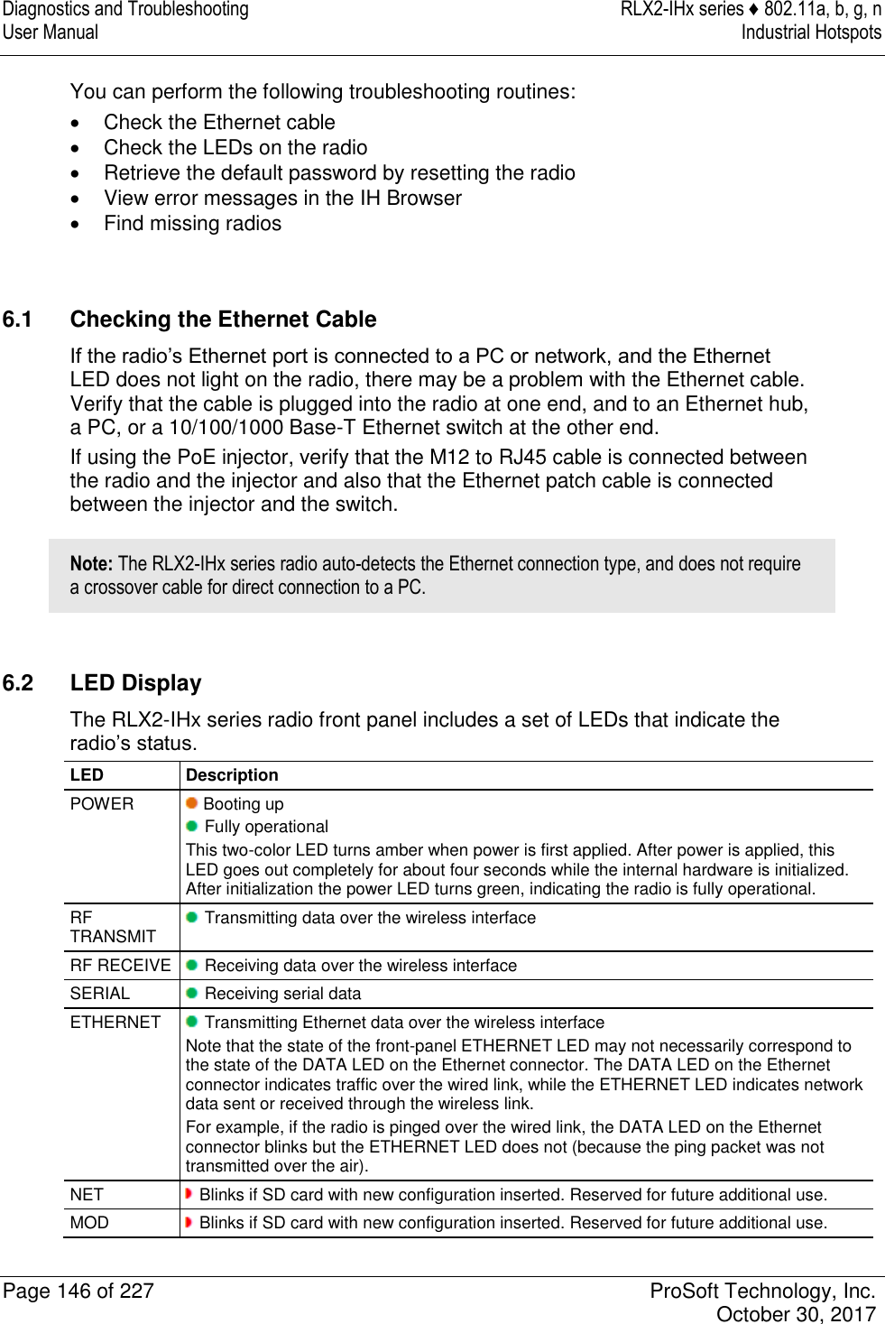
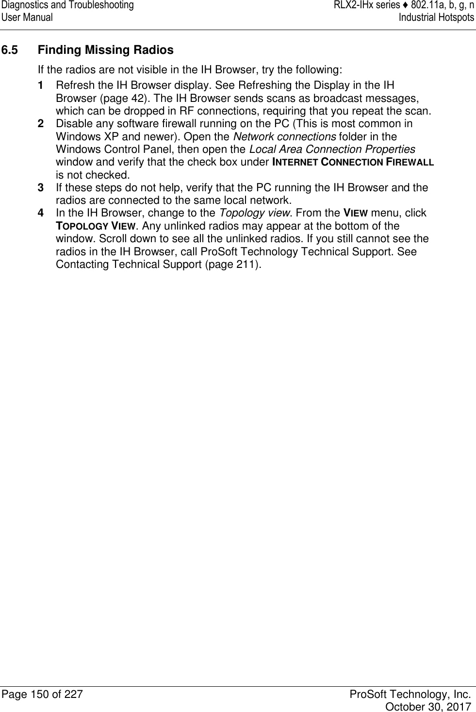
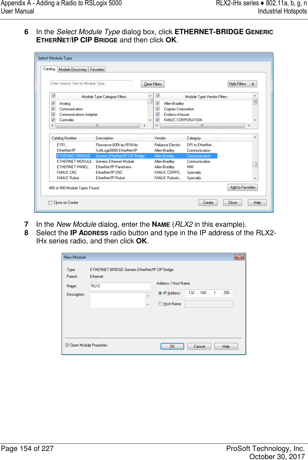
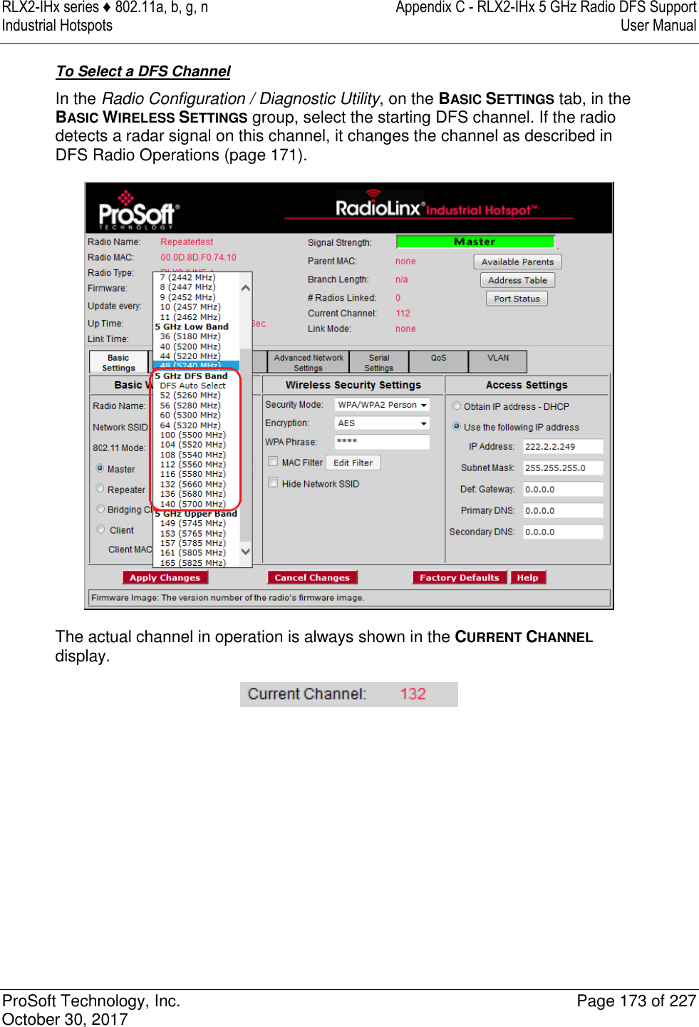
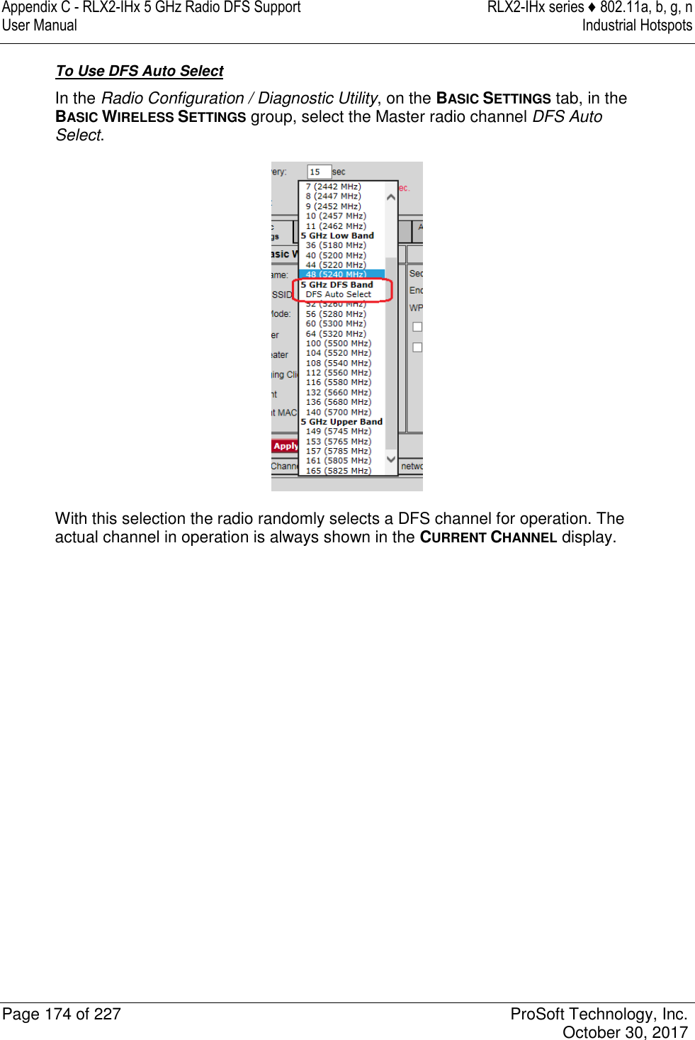
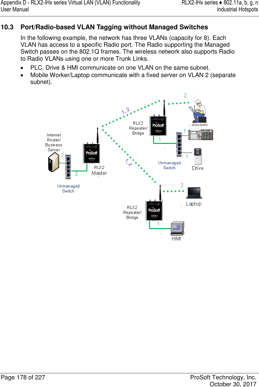
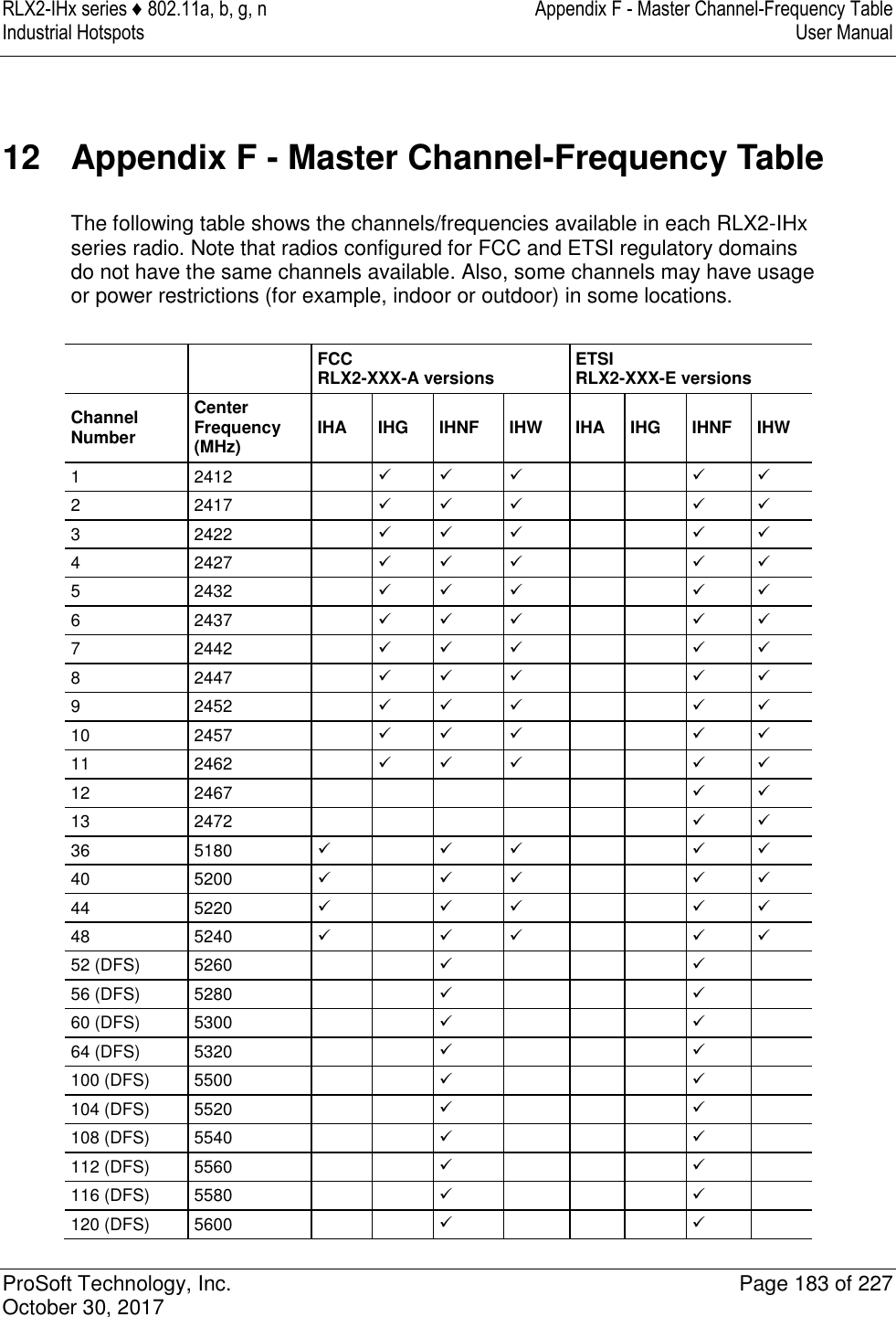
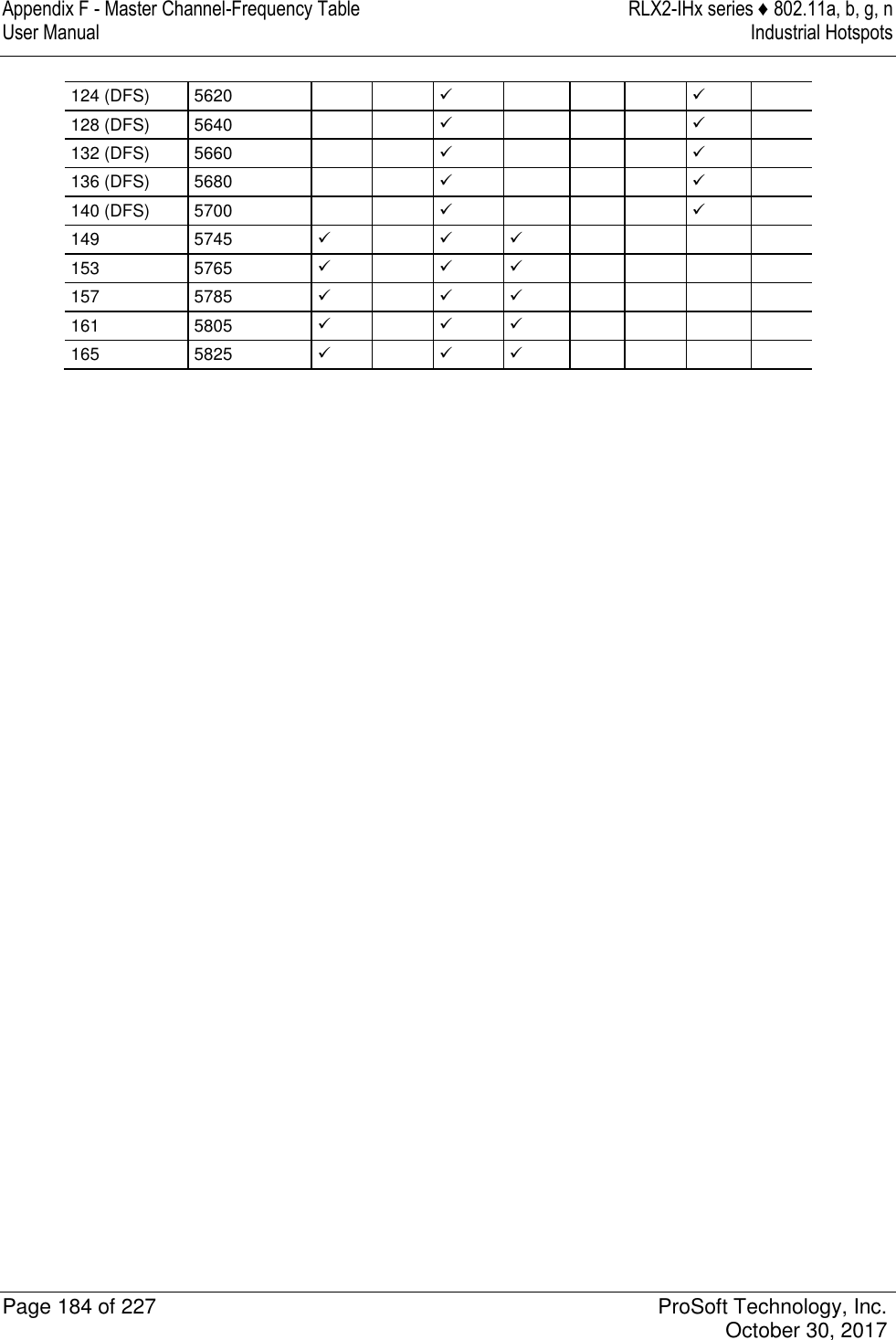
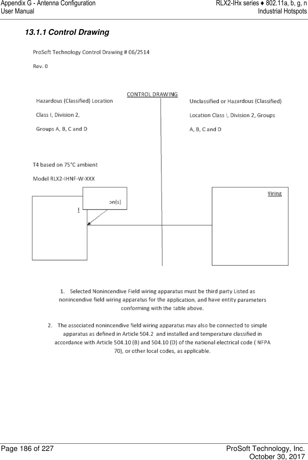
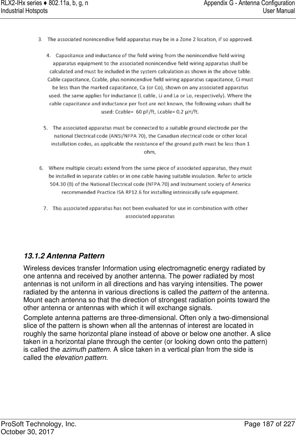
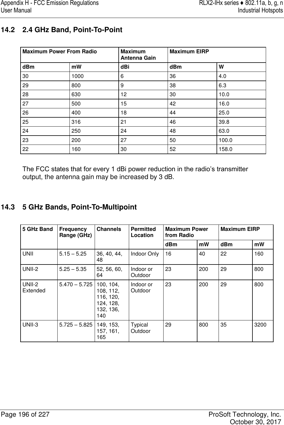
![Appendix C - RLX2-IHx 5 GHz Radio DFS Support RLX2-IHx series ♦ 802.11a, b, g, n User Manual Industrial Hotspots Page 172 of 227 ProSoft Technology, Inc. October 30, 2017 If a Master radio detects radar, it issues a channel change announcement to all Client and Repeater radios in the network. It then moves to a new channel within the Channel Move Time. (Typically, this move time is 500 milliseconds or less.) If the selected channel was not previously checked for the presence of radar, the Master radio must do so for the Channel Availability Check Time before it can begin to transmit. If the newly-selected channel is not a DFS channel, or if the channel was previously monitored for radar since the radio was powered on, transmissions can begin immediately. During the Channel Availability Check Time, a radio blinks all three amber Signal Strength LEDS approximately once per second. If radar is detected on the new channel during the Channel Availability Check Time, the Master radio selects another channel and begins the process again. If a Client or Repeater radio detects radar, in addition to stopping data transmission, must notify its parent of the presence of radar. Each unit receiving a radar notification from a child unit treats it the same as if it had detected radar itself and acts accordingly. Thus radar notifications always reach the Master radio which causes a channel change order to be issued. After a Master radio successfully selects a DFS channel, Repeater or Client radios connect to the Master and scan for radar for an additional 60 seconds (Channel Availability Check Time). If a chain of Repeater radios ultimately connects to a Master radio using a DFS channel, the time to connect is 60 seconds for each Repeater radio in the chain as DFS channels are initially scanned for radar transmissions. 9.1.1 Selecting a DFS 5 GHz Channel For [ModelNumber] Master radios operating in the 5 GHz band, you can select a DFS channel, or let the radio automatically select the DFS channel. DFS channels are a 5 GHz radio parameter only, and apply to all RLX2-IHx series radios except the RLX2-IHG. Note: In some cases, the radio may select a channel in the 5 GHz Upper Band if it does not find an open channel in the 5 GHz DFS Band.](https://usermanual.wiki/ProSoft-Technology/IHNFC/User-Guide-3673268-Page-72.png)
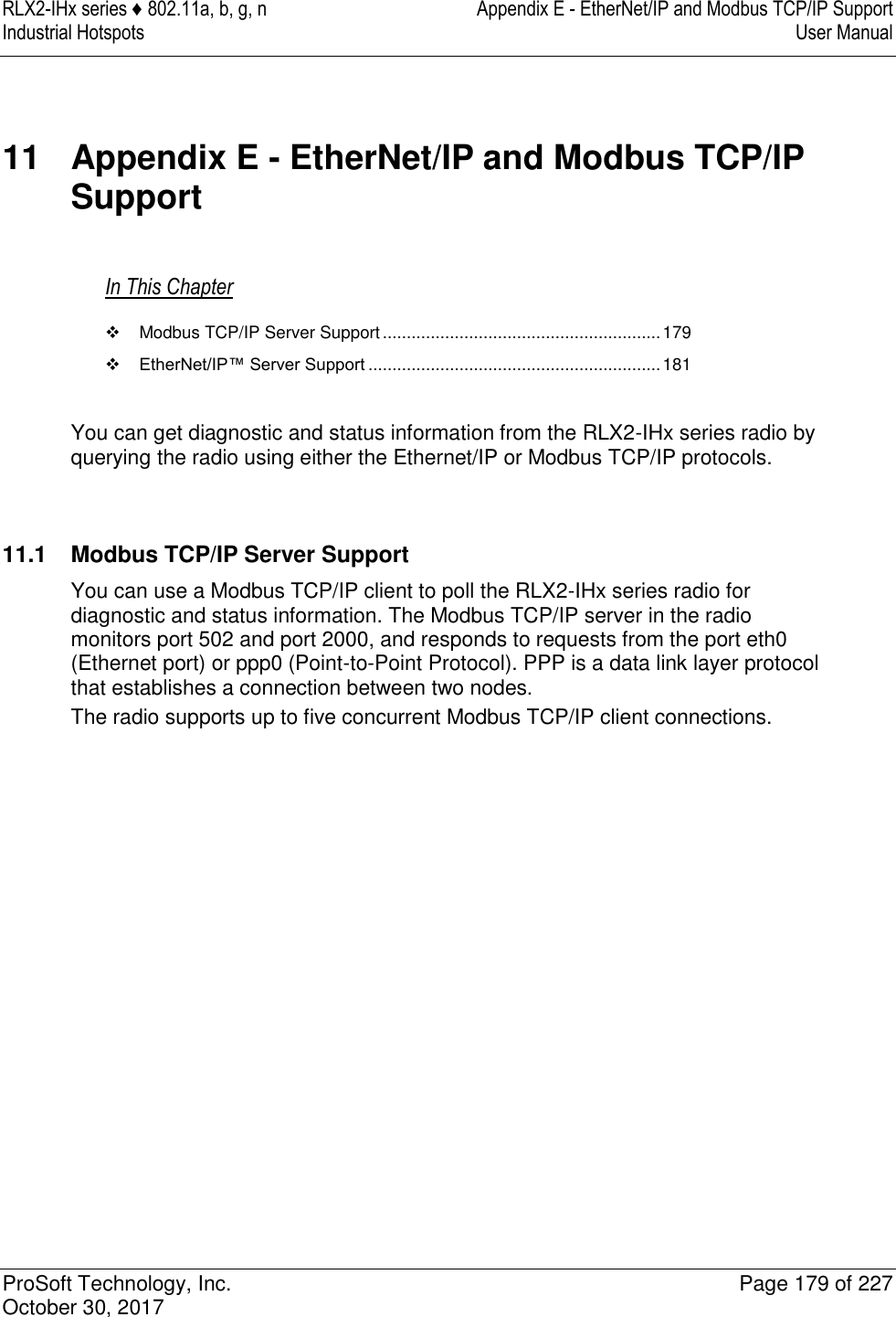
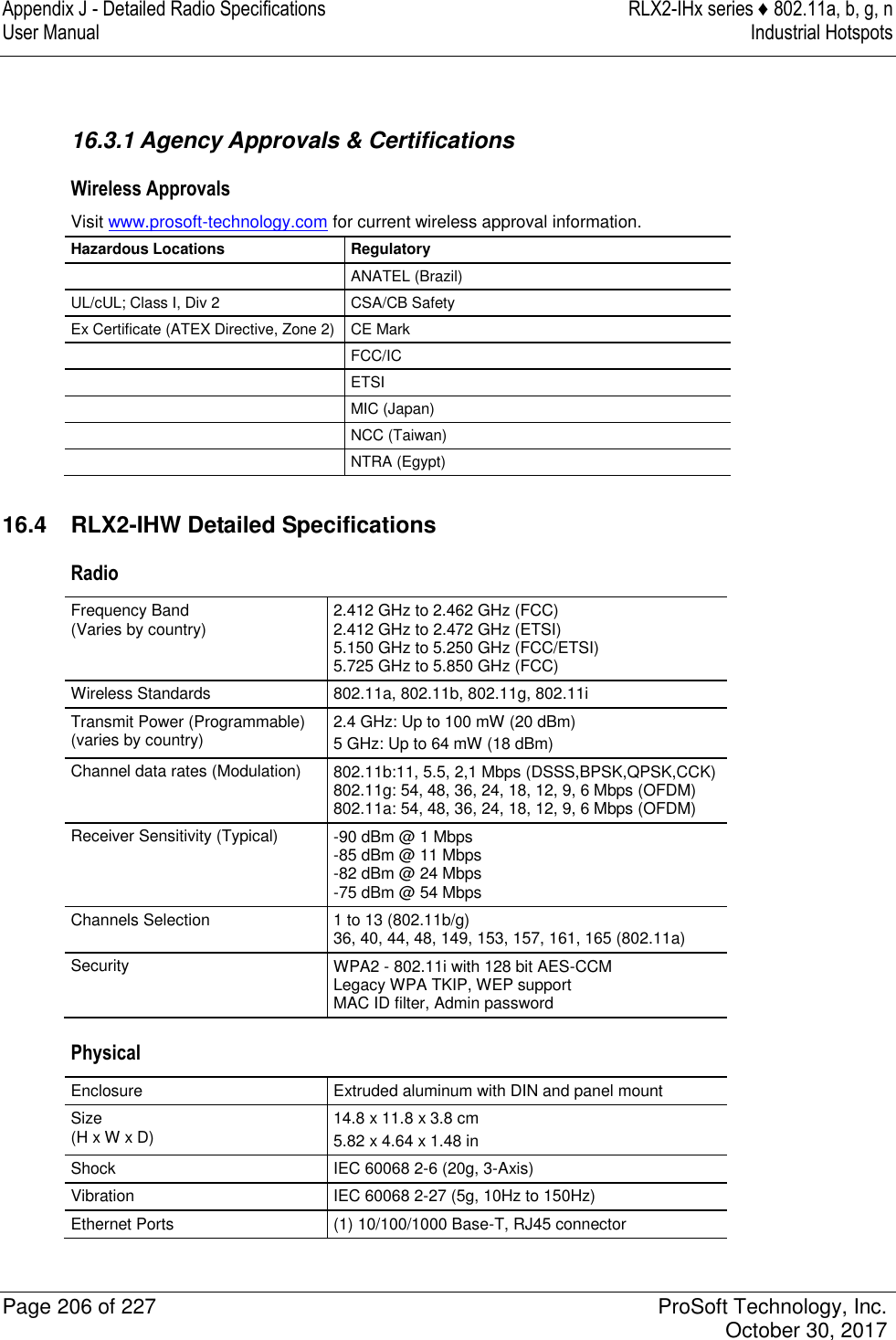
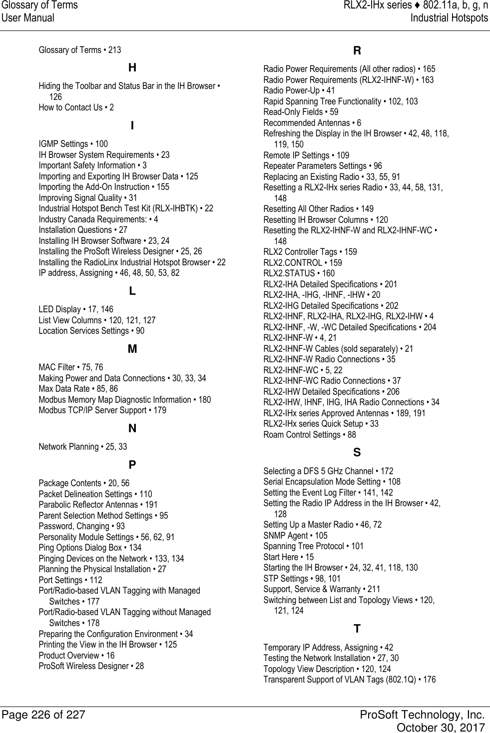
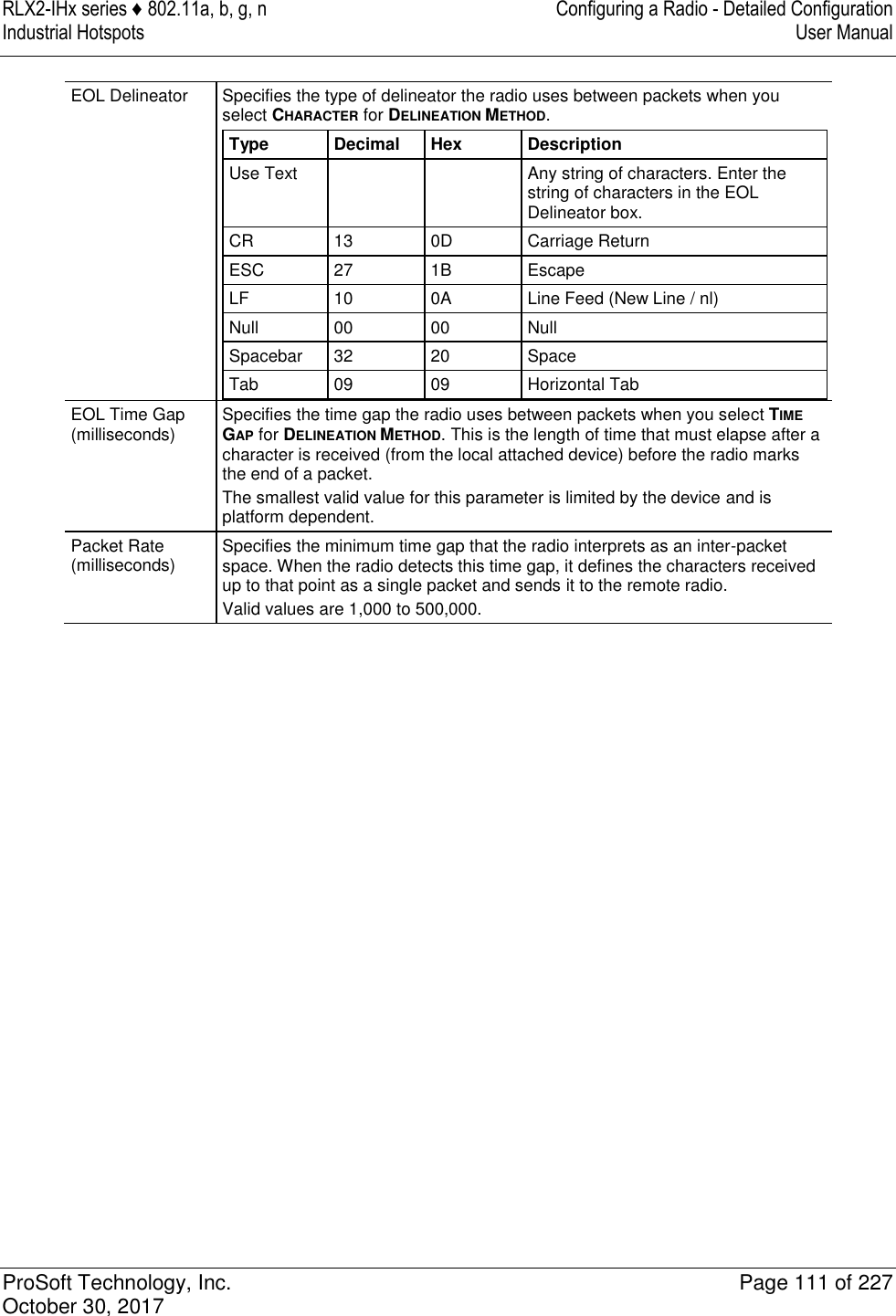
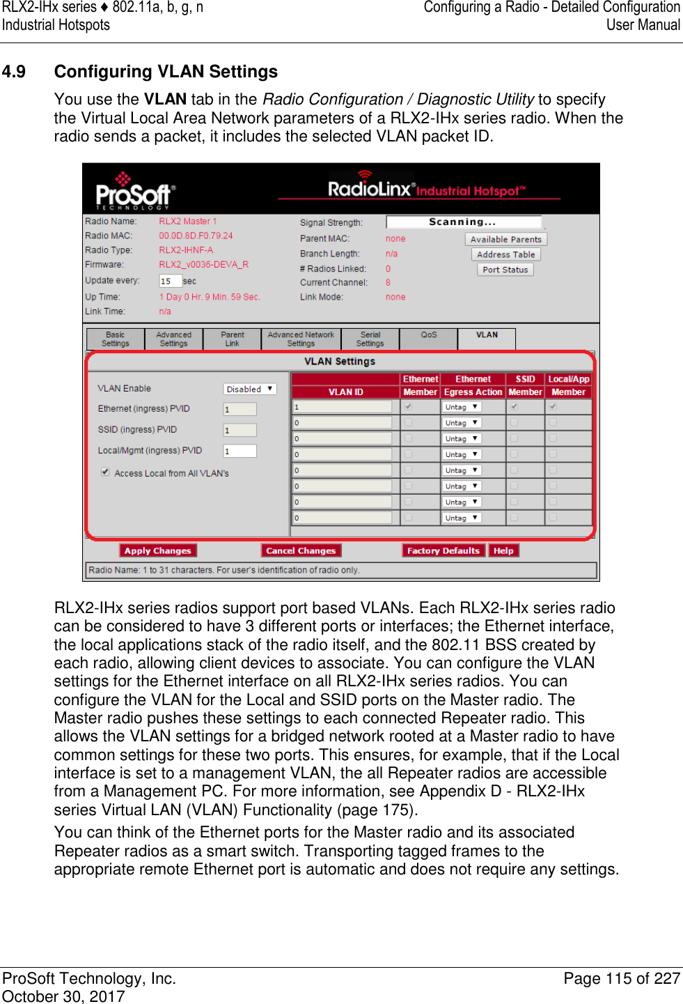
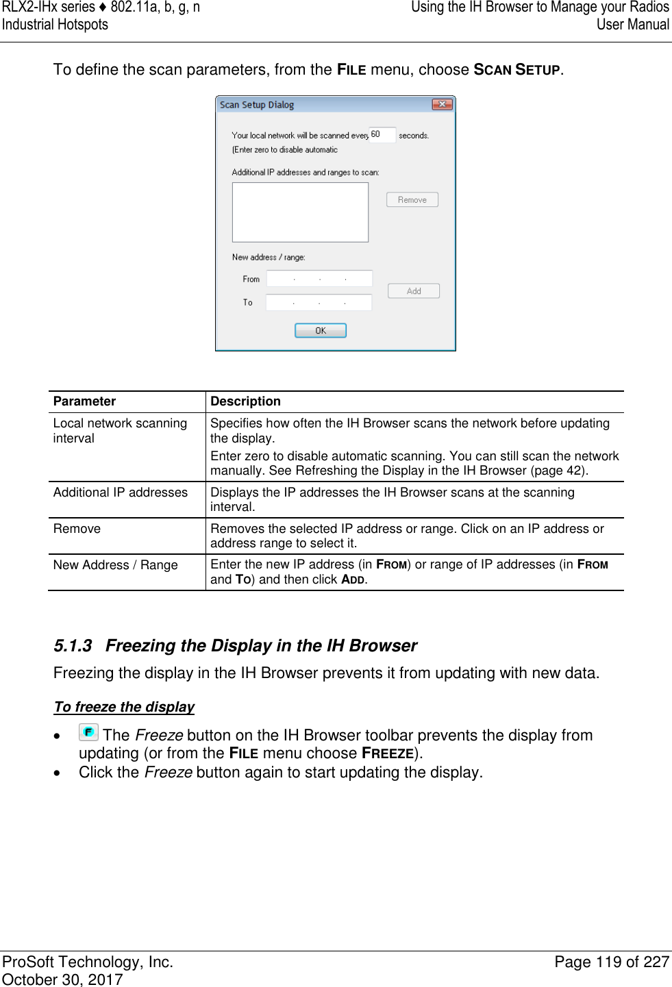
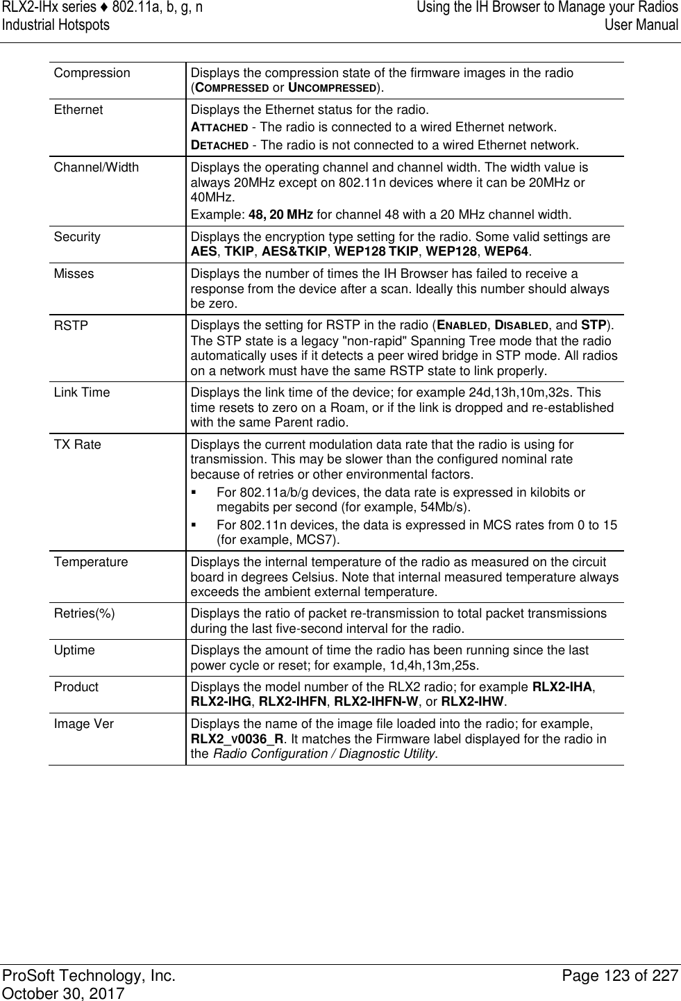
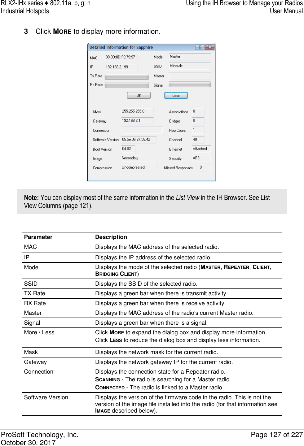
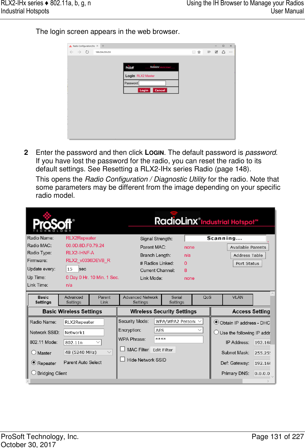
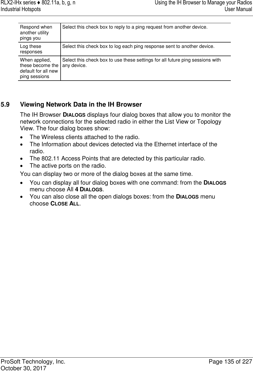
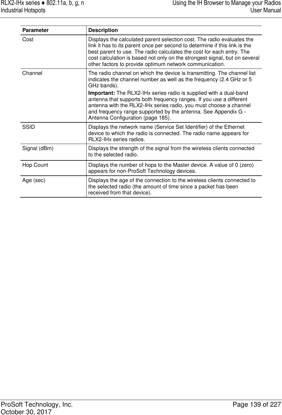
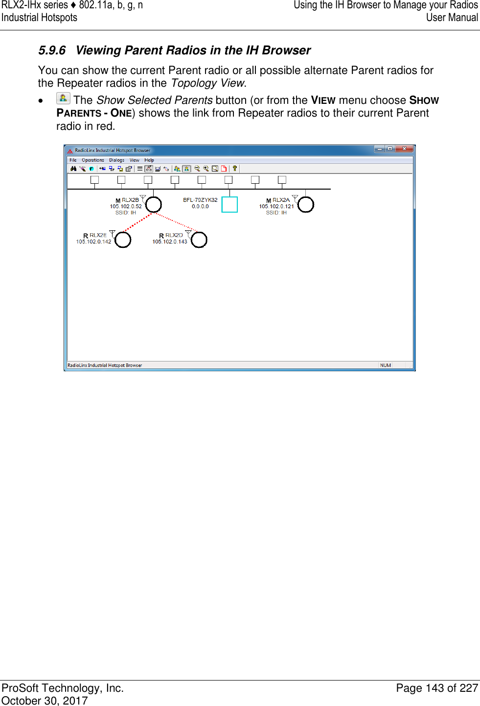
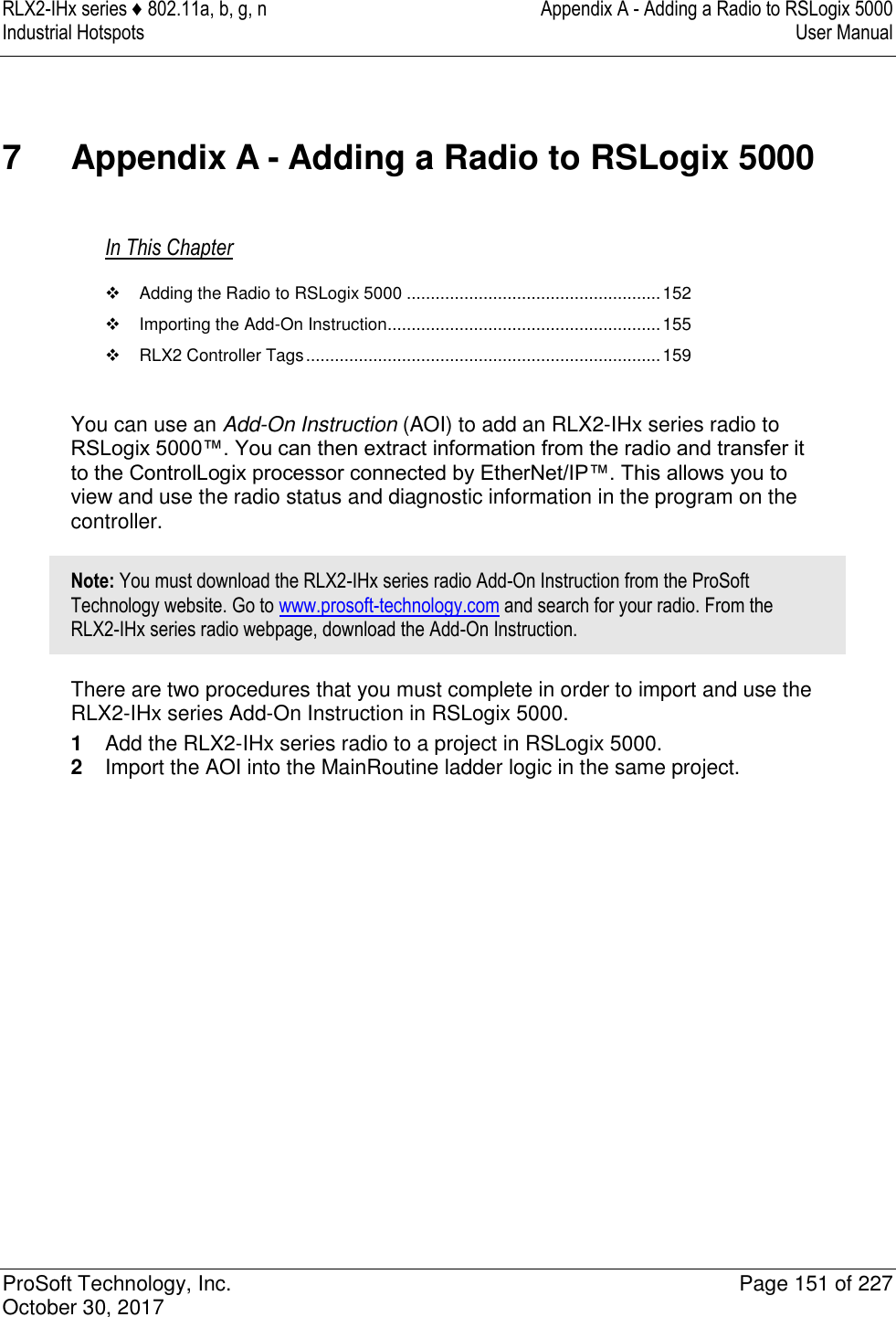
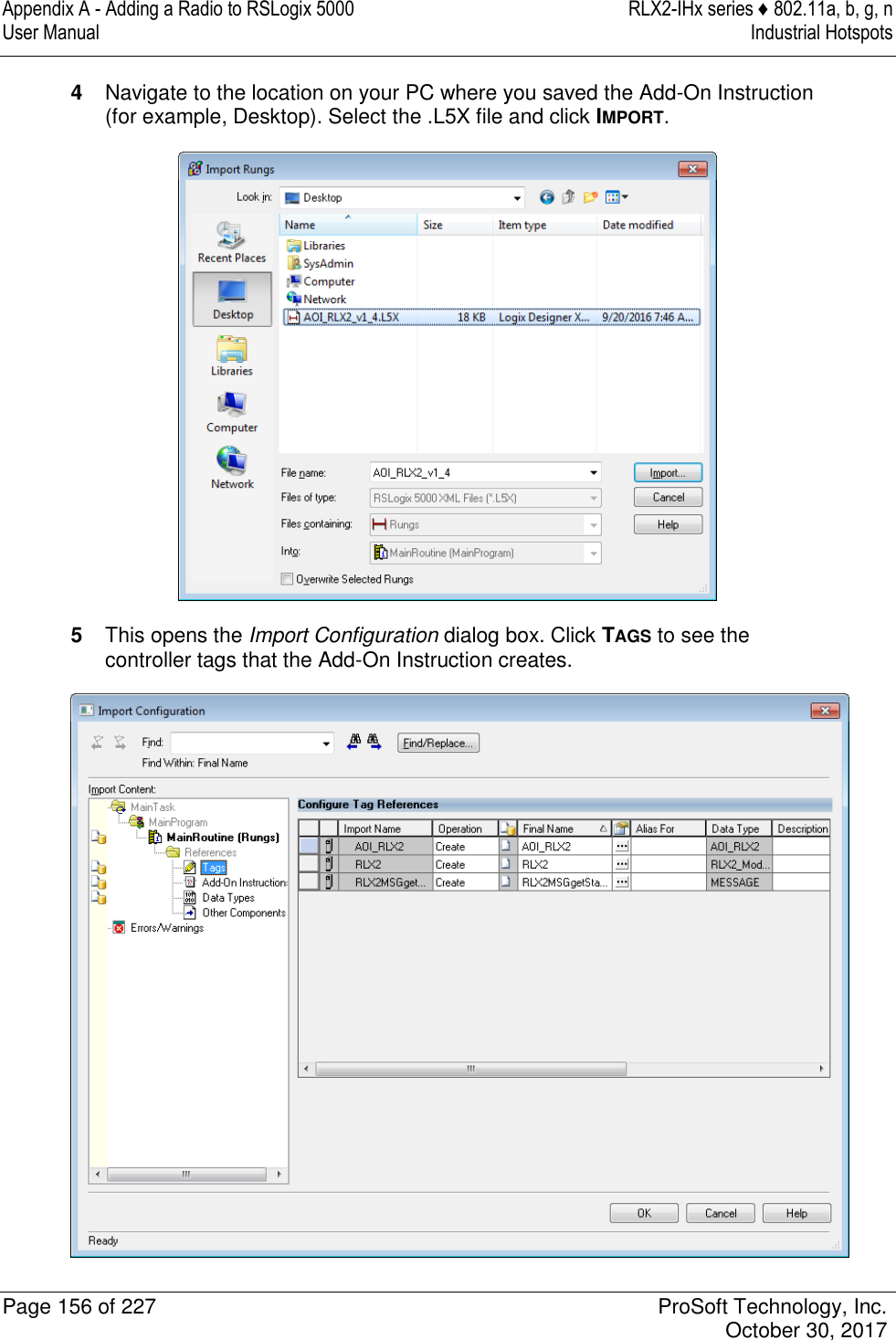
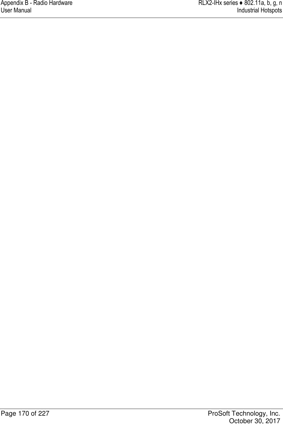
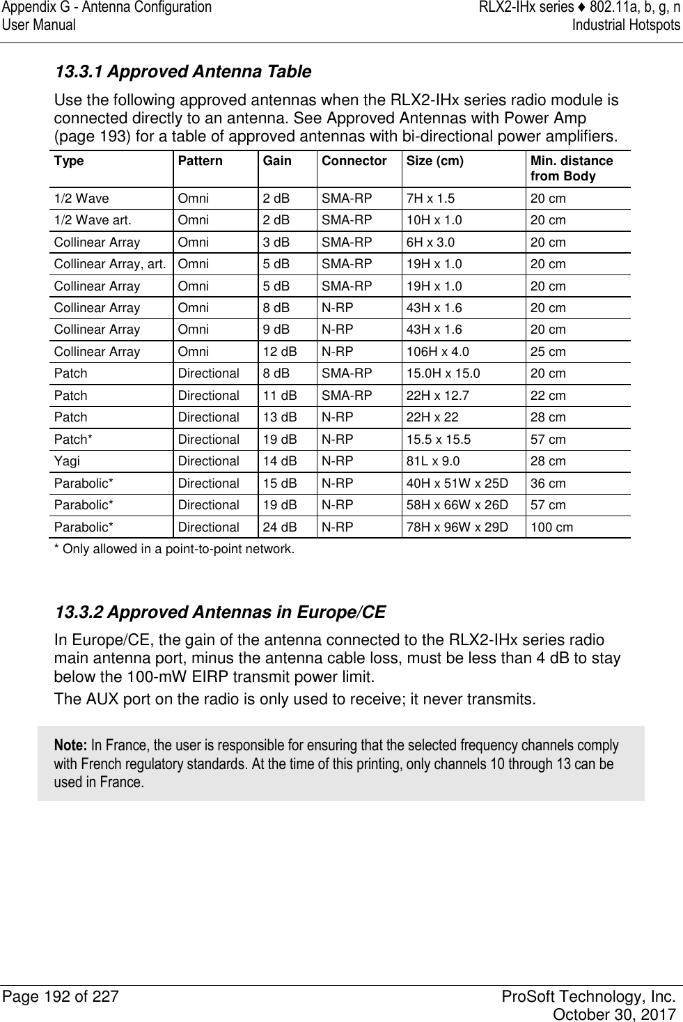
![Appendix E - EtherNet/IP and Modbus TCP/IP Support RLX2-IHx series ♦ 802.11a, b, g, n User Manual Industrial Hotspots Page 180 of 227 ProSoft Technology, Inc. October 30, 2017 11.1.1 Modbus Memory Map Diagnostic Information The topic lists the is the Modbus register addresses that you use to read the RLX2-IHx series radio diagnostic and status information. Name Data Type Access Modbus Register RLX2_Diag.SSID SINT[32] Read 30001 – 30016 RLX2_Diag.IPAddress SINT[4] Read 30017 – 30018 RLX2_Diag.MACAddress SINT[6] Read 30019 – 30021 RLX2_Diag.NeworkMode SINT Read 30022 RLX2_Diag.ConnectionState SINT Read 30023 RLX2_Diag.SignalStrength INT Read 30024 RLX2_Diag.Channel SINT Read 30025 RLX2_Diag.WEP SINT Read 30026 RLX2_Diag.Flags DINT Read 30027 – 30028 RLX2_Diag.MasterMACAddress SINT[6] Read 30029 – 30031 RLX2_Diag.HopCount SINT Read 30032 RLX2_DiagStatus SINT Read 30033 RLX2_Diag.NumAssociations INT Read 30034 RLX2_Diag.NumBridgeAssocs INT Read 30035 RLX2_Diag.TxRadioThroughput INT Read 30036 RLX2_Diag.RxRadioThroughput INT Read 30037 RLX2_Diag.Uptime DINT Read 30038 – 30039 RLX2_Diag.LinkTime DINT Read 30040 – 30041 RLX2_Diag.TxPktThput DINT Read 30042 – 30043 RLX2_Diag.RxPktThput DINT Read 30044 – 30045 RLX2_Diag.ModuleName SINT[32] Read 30046 – 30061 RLX2_Diag.ProductName SINT[32] Read 30062 – 30077 RLX2_Diag.ImageVerStr SINT[28] Read 30078 – 30091 RLX2_Diag.tx_good DINT Read 30092 - 30093 RLX2_Diag.rx_good DINT Read 30094 – 30095 RLX2_Diag.tx_bad DINT Read 30096 – 30097 RLX2_Diag.rx_bad DINT Read 30098 – 30099 RLX2_Diag.tx_directed_frames DINT Read 30100 – 30101 RLX2_Diag.tx_multicast_frames DINT Read 30102 – 30103 RLX2_Diag.tx_broadcast_frames DINT Read 30104 – 30105 RLX2_Diag.rx_directed_frames DINT Read 30106 – 30107 RLX2_Diag.rx_multicast_frames DINT Read 30108 – 30109 RLX2_Diag.rx_broadcast_frames DINT Read 30110 – 30111 RLX2_Diag.rx_crc_error DINT Read 30112 - 30113 Modbus Function Code 4 (Read Input Registers(3X)) is supported.](https://usermanual.wiki/ProSoft-Technology/IHNFC/User-Guide-3673268-Page-80.png)
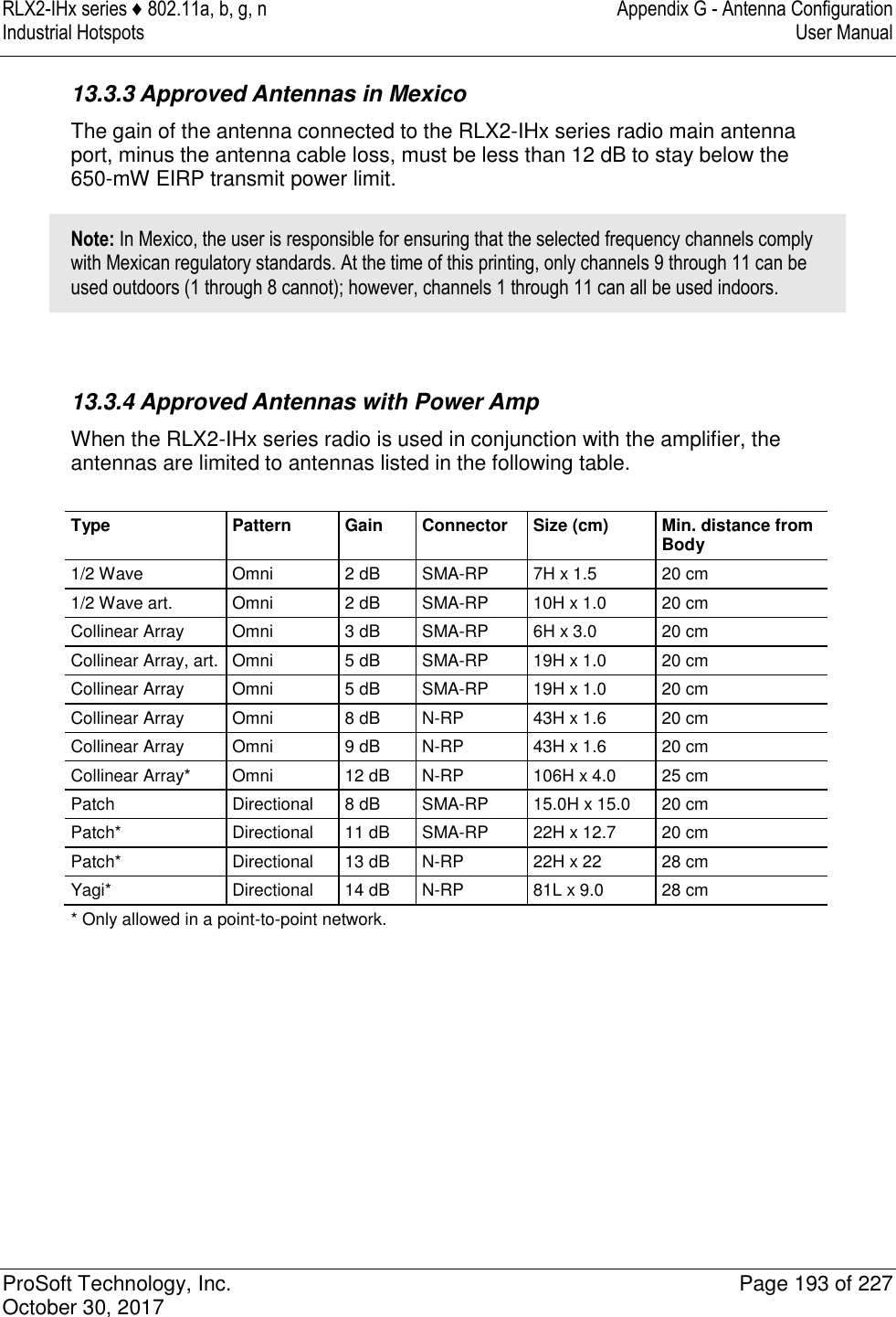
![RLX2-IHx series ♦ 802.11a, b, g, n Appendix E - EtherNet/IP and Modbus TCP/IP Support Industrial Hotspots User Manual ProSoft Technology, Inc. Page 181 of 227 October 30, 2017 11.2 EtherNet/IP™ Server Support The topic lists the is the CIP™ object definition that you use to read the RLX2-IHx series radio diagnostic and status information. Class ID: 0xA1 (161) Number of Instances: 1 CIP Data Tag Name Data Type Access RLX2_Diag.SSID SINT[32] Read RLX2_Diag.IPAddress SINT[4] Read RLX2_Diag.MACAddress SINT[6] Read RLX2_Diag.NetworkMode SINT Read RLX2_Diag.ConnectionState SINT Read RLX2_Diag.SignalStrength INT Read RLX2_Diag.Channel SINT Read RLX2_Diag.WEP SINT Read RLX2_Diag.Flags DINT Read RLX2_Diag.MasterMACAddress SINT[6] Read RLX2_Diag.HopCount SINT Read RLX2_Diag.Status SINT Read RLX2_Diag.NumAssociations INT Read RLX2_Diag.NumBridgeAssocs INT Read RLX2_Diag.TxRadioThroughput INT Read RLX2_Diag.Uptime INT Read RLX2_Diag.Linktime DINT Read RLX2_Diag.TxPktThput DINT Read RLX2_Diag.RxPktThput DINT Read RLX2_Diag.ModuleName DINT Read RLX2_Diag.ProductName SINT[32] Read RLX2_Diag.ImageVerStr SINT[32] Read RLX2_Diag.tx_good SINT[28] Read RLX2_Diag.rx_good DINT Read RLX2_Diag.tx_bad DINT Read RLX2_Diag.rx_bad DINT Read RLX2_Diag.tx_directed_frames DINT Read RLX2_Diag.tx_multicast_frames DINT Read RLX2_Diag.tx_broadcast_frames DINT Read RLX2_Diag.rx_directed_frames DINT Read RLX2_Diag.rx_multicast_frames DINT Read RLX2_Diag.rx_broadcast_frames DINT Read RLX2_Diag.rx_crc_err DINT Read](https://usermanual.wiki/ProSoft-Technology/IHNFC/User-Guide-3673268-Page-81.png)
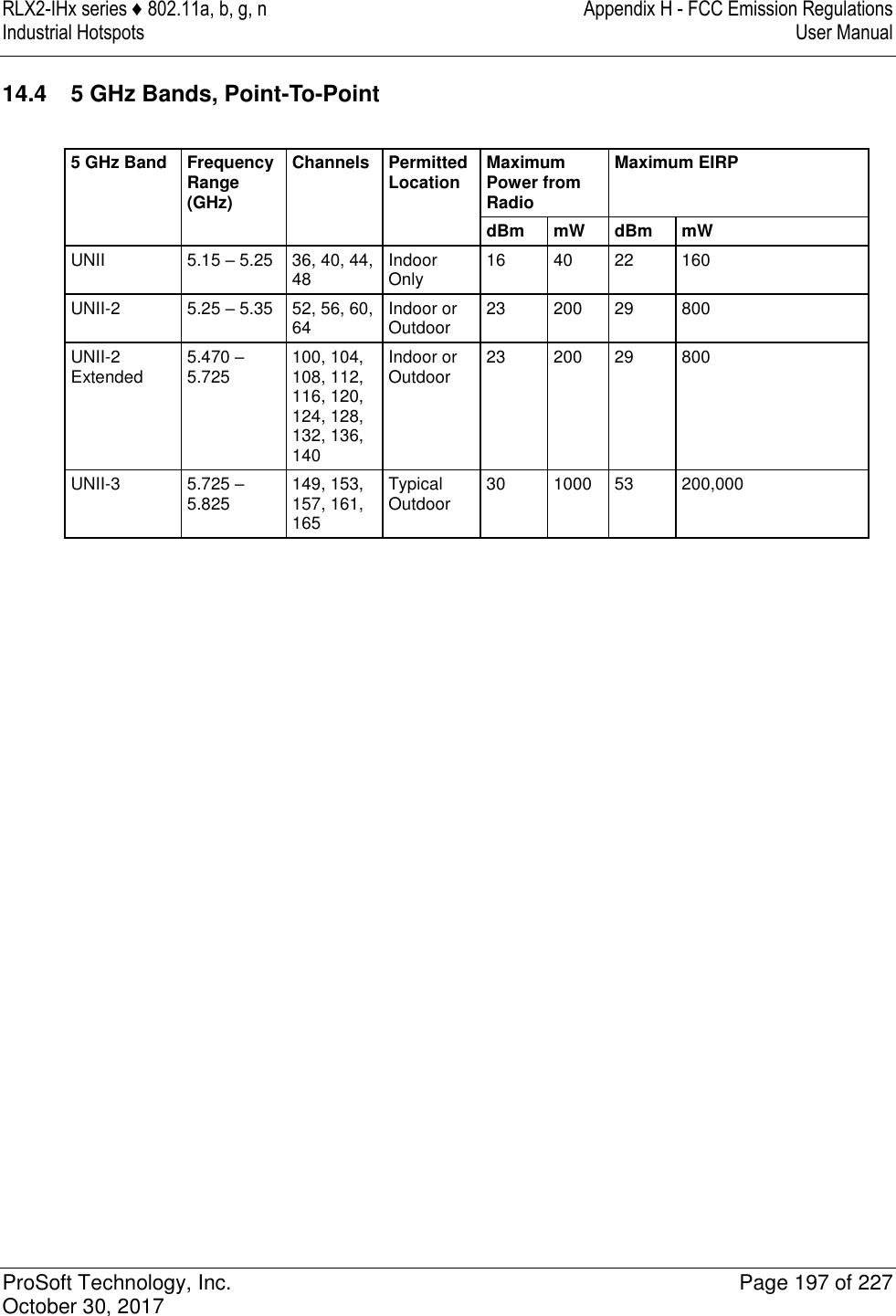

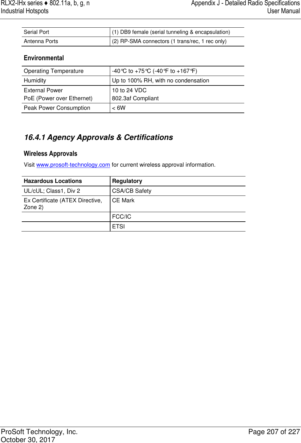
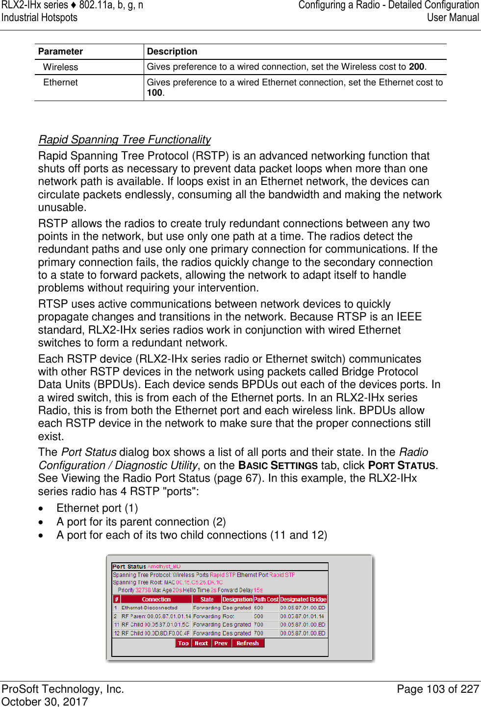
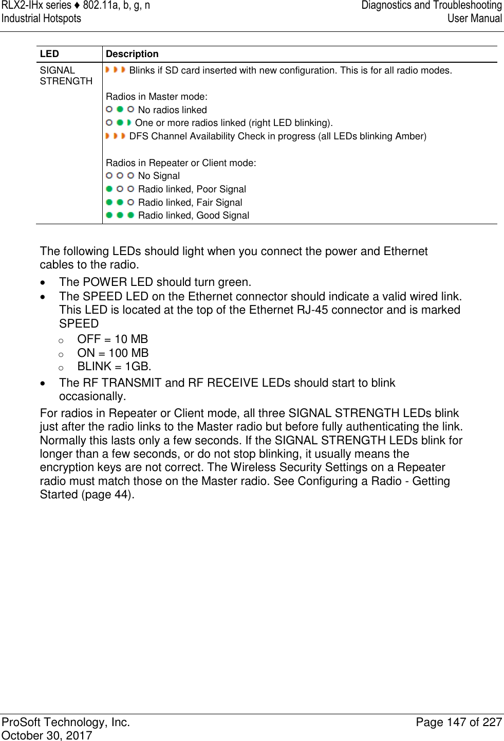
![Appendix J - Detailed Radio Specifications RLX2-IHx series ♦ 802.11a, b, g, n User Manual Industrial Hotspots Page 202 of 227 ProSoft Technology, Inc. October 30, 2017 Environmental Operating Temperature -40°C to +75°C (-40°F to +167°F) Humidity Up to 100% RH, with no condensation External Power Power over Ethernet 10 VDC to 24 VDC 802.3af Compliant Peak Power Consumption < 7W 16.1.1 Agency Approvals & Certifications Wireless Approvals Visit www.prosoft-technology.com for current wireless approval information. Hazardous Locations Regulatory UL/cUL; Class1, Div 2 CSA/CB Safety Ex Certificate (ATEX Directive, Zone 2) CE Mark FCC/IC ETSI 16.2 RLX2-IHG Detailed Specifications Radio Frequency Band (Varies by country) 802.11g: 2.412 GHz to 2.462 GHz (FCC) 2.412 GHz to 2.472 GHz (ETSI) Wireless Standards 802.11b, 802.11g, 802.11i Transmit Power (Programmable) (varies by country) Up to 24 dBm (250 mW) Channel Data Rates (Modulation) 802.11g: (OFDM) Mbps 54, 48, 36, 24, 18, 12, 9, and 6 802.11b: (DSS) Mbps 11, 5.5, 2, and 1 Receiver Sensitivity (Typical) -94 dBm @ 1 Mbps -92 dBm @ 11 Mbps -84 dBm @ 24 Mbps -72 dBm @ 54 Mbps Channel Selection 802.11g: 1 to 11 (FCC), 1 to 13 (ETSI) Security WPA2 Enterprise – 802.11i AES w/RADIUS [PEAP, TTLS, TLS, EAP] WPA2 Personal – 802.11i AES w/Passphrase Legacy WPA TKIP, WEP support](https://usermanual.wiki/ProSoft-Technology/IHNFC/User-Guide-3673268-Page-102.png)