ProSoft Technology IHNFC WIFI HOTSPOT User Manual RLX2 IHx
ProSoft Technology, Inc WIFI HOTSPOT RLX2 IHx
Users Manual
RLX2-IHx series ♦ 802.11a, b, g, n Configuring a Radio - Detailed Configuration
Industrial Hotspots User Manual
ProSoft Technology, Inc. Page 101 of 227
October 30, 2017
Parameter
Description
IGMP Query Interval
Specifies the number of seconds between queries (if the timer is not
pre-empted by a query from another device).
By RFC specification, only one device on a network should generate
IGMP queries. As such, the radio only sends an IGMP query if another
device has not sent a query within the radio's IGMP QUERY INTERVAL
setting, even if IGMP QUERY GENERATION is enabled.
Multicast State Count
Specifies the number of queries the radio generates before a device is
removed from the multicast group on this radio if no response is
received from the device.
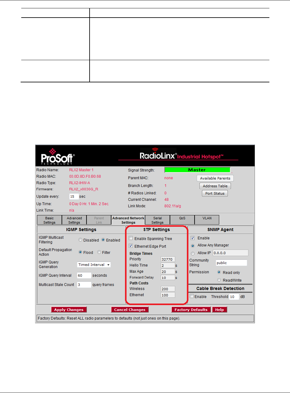
4.6.2 STP Settings
You use the parameters in the STP SETTING group in the Radio Configuration /
Diagnostic Utility to specify the Spanning Tree Protocol parameters of your
RLX2-IHx series radio.

Configuring a Radio - Detailed Configuration RLX2-IHx series ♦ 802.11a, b, g, n
User Manual Industrial Hotspots
Page 102 of 227 ProSoft Technology, Inc.
October 30, 2017
Parameter
Description
Enable Spanning Tree
Select this check box to enable Spanning Tree Protocol (STP).
If you enable Spanning Tree (recommended), the radio blocks
redundant connections. Additionally, the radio flushes the Ethernet
switch table when the network topology changes. See Rapid
Spanning Tree Functionality (page 103).
If you disable Spanning Tree (clear the check box), there can be
redundant connections if the radio creates multiple radio links in
parallel with each other. This also disables the other parameters in
the STP SETTINGS group.
All RLX2-IHx series radios support the Rapid Spanning Tree Protocol
(RSTP), and default to this mode when you enable Spanning Tree.
Ethernet Edge Port
Select this check box to enable the Ethernet Edge Port function
(recommended) when no RSTP device is connected to the Ethernet port.
This allows immediate communication through the Ethernet port.
Because RSTP is an active protocol, it depends on communication
between RSTP devices. If no RSTP device is connected to the radio’s
Ethernet port, the handshake cannot take place. In this case, RSTP
reverts to STP. This means that the Ethernet port is forced to adhere to
the timer based transition protocol of STP.
Therefore on network transitions and power up, communications are not
allowed over the Ethernet port for 30 to 45 seconds unless you enable
ETHERNET EDGE PORT. This setting specifies that no redundant
connections exist out the Ethernet port and communication can start
immediately. If for some reason the radio receives a BPDU (bridge
protocol data unit) on this port, the RSTP protocol negotiates properly
and handles any possible redundant paths.
Note: You can select ETHERNET EDGE PORT without selecting ENABLE
SPANNING TREE.
Bridge Times
Configures the timing intervals to use.
Priority
Determines which device is the root of the RSTP. The RSTP device with
the lowest priority becomes the root bridge.
The accepted standard value for this is 32768. If wired switches
exist in the network that support RSTP, they should always be
allowed to be the root.
For Master radios, set this value to 32769 to prevent the radio from
being the root over a wired switch.
For Repeater radios, set this value to 32770. This specifies that if
the network only has RLX2-IHx series radios, the Master radio
becomes the root.
Hello Time
Specifies the rate at which the radio sends out BPDUs. The
recommended industry standard is 2 seconds.
Max Age
Specifies the age limit for protocol information for a port.
The radio measures the age of the received protocol information
recorded for a port and discards it when the information's age limit
exceeds this value. The timeout value for this timer is the maximum age
parameter of the root.
Forward Delay
Specifies the timeout for time spent by a port in the learning and listening
states. The timeout value is the forward delay parameter of the root.
Path Costs
RSTP and STP algorithms use a cost to determine which connections
should be used in the Spanning Tree. The radio forms the Spanning
Tree by determining the lowest cost paths from any RSTP device back
to the root.
RLX2-IHx series ♦ 802.11a, b, g, n Configuring a Radio - Detailed Configuration
Industrial Hotspots User Manual
ProSoft Technology, Inc. Page 103 of 227
October 30, 2017
Parameter
Description
Wireless
Gives preference to a wired connection, set the Wireless cost to 200.
Ethernet
Gives preference to a wired Ethernet connection, set the Ethernet cost to
100.
Rapid Spanning Tree Functionality
Rapid Spanning Tree Protocol (RSTP) is an advanced networking function that
shuts off ports as necessary to prevent data packet loops when more than one
network path is available. If loops exist in an Ethernet network, the devices can
circulate packets endlessly, consuming all the bandwidth and making the network
unusable.
RSTP allows the radios to create truly redundant connections between any two
points in the network, but use only one path at a time. The radios detect the
redundant paths and use only one primary connection for communications. If the
primary connection fails, the radios quickly change to the secondary connection
to a state to forward packets, allowing the network to adapt itself to handle
problems without requiring your intervention.
RTSP uses active communications between network devices to quickly
propagate changes and transitions in the network. Because RTSP is an IEEE
standard, RLX2-IHx series radios work in conjunction with wired Ethernet
switches to form a redundant network.
Each RSTP device (RLX2-IHx series radio or Ethernet switch) communicates
with other RSTP devices in the network using packets called Bridge Protocol
Data Units (BPDUs). Each device sends BPDUs out each of the devices ports. In
a wired switch, this is from each of the Ethernet ports. In an RLX2-IHx series
Radio, this is from both the Ethernet port and each wireless link. BPDUs allow
each RSTP device in the network to make sure that the proper connections still
exist.
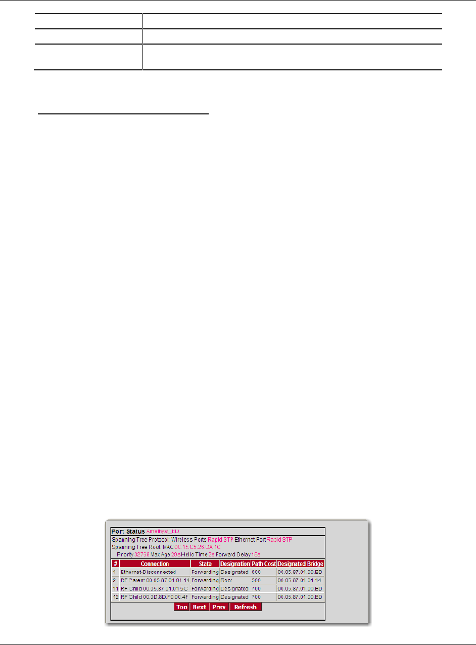
The Port Status dialog box shows a list of all ports and their state. In the Radio
Configuration / Diagnostic Utility, on the BASIC SETTINGS tab, click PORT STATUS.
See Viewing the Radio Port Status (page 67). In this example, the RLX2-IHx
series radio has 4 RSTP "ports":
Ethernet port (1)
A port for its parent connection (2)
A port for each of its two child connections (11 and 12)

Configuring a Radio - Detailed Configuration RLX2-IHx series ♦ 802.11a, b, g, n
User Manual Industrial Hotspots
Page 104 of 227 ProSoft Technology, Inc.
October 30, 2017
BPDUs are sent out the port at a rate called the Hello Time set in the Radio
Configuration / Diagnostic Utility on the ADVANCED NETWORK SETTINGS tab. The
accepted standard value for this parameter is 2 seconds. If a radio (or any other
RSTP device) does not get a BPDU from a device for a time period equal to two
Hello Times, the radio assumes the RSTP device is no longer available. The
radio can then open a redundant path if one is available. This process is much
like the STP process. If other devices on the network are not operating in Rapid
Spanning Tree mode, the radio reverts to normal Spanning Tree operation on the
ports connected to those devices.
RSTP provides a performance enhancement over STP.
A radio using the STP algorithm reverts its port to the listening state, and then
to the learning state, before returning to the forwarding state. Each of these
states takes at least 15 seconds, during which the STP devices are listening
for BPDUs to re-negotiate the network topology.
A radio using the RSTP algorithm uses active handshaking between adjacent
RSTP devices to re-negotiate the network topology. This process takes only
one to two seconds.
Each RLX2-IHx series radio contains a switch table that tells the radio how to
forward Ethernet packets to get them to their correct destination. When the
network topology changes, the radio immediately flushes its Ethernet switch
table. This allows the radio to pass traffic immediately over the new network
topology and learn the configuration in the process. Until the radio completely
learns the new topology, it broadcasts the packets to their destination. As the
radios see each packet and rebuilds the Ethernet switch table, the radios return
to directing packets to their destinations.
RLX2-IHx series ♦ 802.11a, b, g, n Configuring a Radio - Detailed Configuration
Industrial Hotspots User Manual
ProSoft Technology, Inc. Page 105 of 227
October 30, 2017
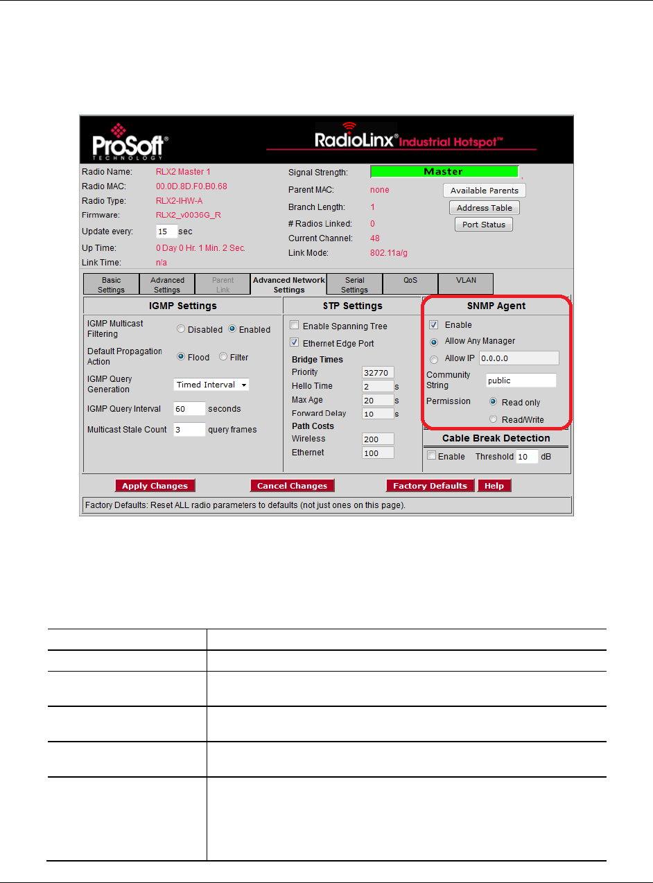
4.6.3 SNMP Agent
You use the parameters in the SNMP AGENT group in the Radio Configuration /
Diagnostic Utility to specify the Simple Network Management Protocol
parameters of your RLX2-IHx series radio.
SNMP is a network management protocol that is often used with TCP/IP and
Ethernet. It offers an alternative to using the Radio Configuration / Diagnostic
Utility, and allows you to use an SNMP manager application to change radio
settings and view diagnostics.
Parameter
Description
Enable
Select this check box to enable the following SNMP agent.
Allow Any Manager
Specifies that any user can change the radio configuration from any
computer using SNMP.
Allow IP
Specifies that only an SNMP manager with a particular IP address can
change the radio configuration. You must enter the IP address.
Community String
Specifies a community string (similar to a password) that an SNTP
manager must use to access the radio’s SNMP agent.
Permission
Specifies the permission level to assign to this radio.
READ ONLY - The SNMP manager can view, but cannot change the
radio configuration.
READ/WRITE - The SNMP manager can view and make changes to the
radio configuration.
Configuring a Radio - Detailed Configuration RLX2-IHx series ♦ 802.11a, b, g, n
User Manual Industrial Hotspots
Page 106 of 227 ProSoft Technology, Inc.
October 30, 2017
The RLX2-IHx series radio's SNMP agent supports SNMP protocol version
1.4 and 2.
MIBs:
o RFC12133-MIB (partial; internet.mgmt.MIB-2.system, .interfaces, .snmp)
o ROMAP-MIB (internet.private.enterprises.romap)
It also supports a selection of standard SNMP traps, including Cold Start,
which the radio sends when it initializes.
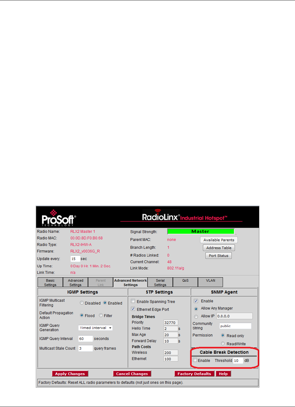
4.6.4 Cable Break Detection
One common application interconnects a line of RLX2-IHx Masters with
Radiating Cable, allowing mobile platforms to move down the line roaming from
Master to Master. The radiating cable between the Masters allows them to
receive each other's packets, in particular each other's Beacon frames. It is
therefore possible for a Master to detect if the Radiating Cable between itself and
the next or previous Master is broken or damaged. When enabled, this feature
will produce an SNMP Trap whenever it detects an RSSI drop to one of its
Monitored Peers.
A cable break is defined as a change in RSSI greater than the Cable Break
Threshold. The RLX2-IHx will automatically determine the closest Peers and will
adopt a baseline RSSI from each Peer when it is first picked to be monitored.
RLX2-IHx series ♦ 802.11a, b, g, n Configuring a Radio - Detailed Configuration
Industrial Hotspots User Manual
ProSoft Technology, Inc. Page 107 of 227
October 30, 2017
Parameter
Description
Enable
Select this check box to enable the Cable Break Detection feature
Threshold
Configures the RSSI change (in dB) observed while monitoring a
neighboring RLX2-IHx Master that will trigger a cable break indication
via an SNMP Trap.
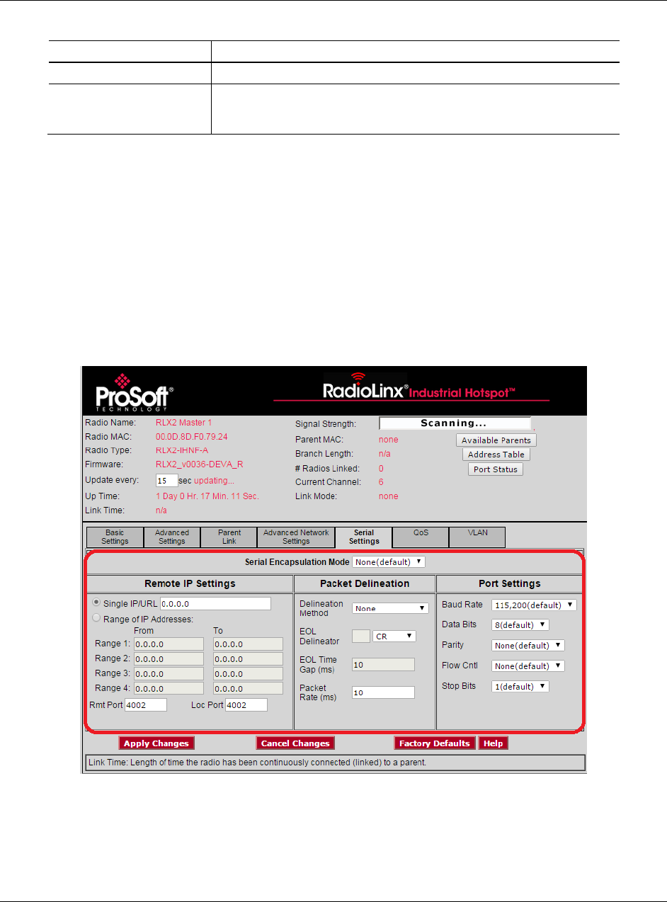
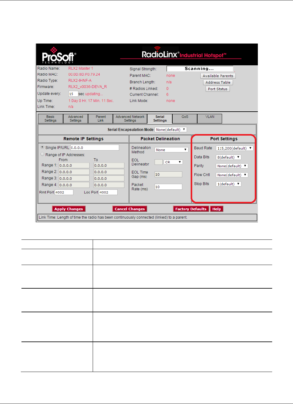
4.7 Configuring Serial Settings
You use the SERIAL SETTINGS tab in the Radio Configuration / Diagnostic Utility
to specify the serial communication parameters for a RLX2-IHx series radio.
Serial Settings includes four groups:
SERIAL ENCAPSULATION MODE
REMOTE IP SETTINGS
PACKET DELINEATION
PORT SETTINGS
Configuring a Radio - Detailed Configuration RLX2-IHx series ♦ 802.11a, b, g, n
User Manual Industrial Hotspots
Page 108 of 227 ProSoft Technology, Inc.
October 30, 2017
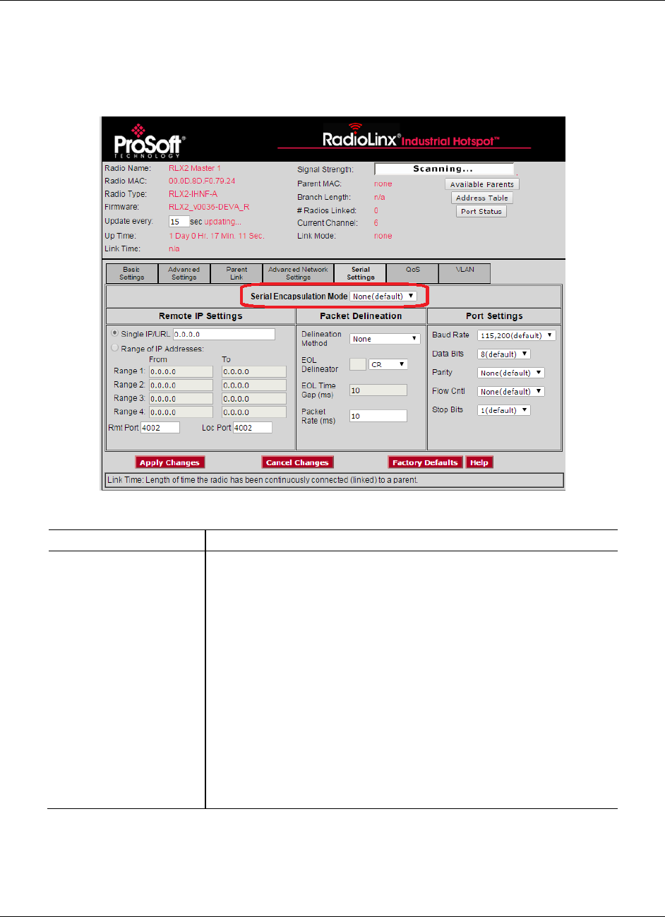
4.7.1 Serial Encapsulation Mode Setting
You use the SERIAL ENCAPSULATION MODE parameter in the Radio Configuration
/ Diagnostic Utility to specify the serial encapsulation parameter of your RLX2-
IHx series radio.
Parameter
Description
Serial Encapsulation
Mode
Specifies the serial encapsulation that the radio uses in serial
communication.
NONE - No serial data encapsulation.
UDP - You can use programs on networked computers to send short
messages or Datagrams. The radio uses the serial port to transmit and
receive packets.
Note: In UDP mode if you enter a multicast group address in the
REMOTE IP SETTINGS group parameters, then packets are sent to that
address or addresses.
TCP SERVER - Only connections from this address will be accepted.
Once the session is established, the serial port is enabled to transmit
and receive packets.
Note: To accept connections from any IP address the parameter
should be set to 0.0.0.0.
TCP CLIENT - In TCP Client mode, a TCP connection will be established
with this address.
When the session is established, the serial port is enabled to transmit and
receive packets.
RLX2-IHx series ♦ 802.11a, b, g, n Configuring a Radio - Detailed Configuration
Industrial Hotspots User Manual
ProSoft Technology, Inc. Page 109 of 227
October 30, 2017
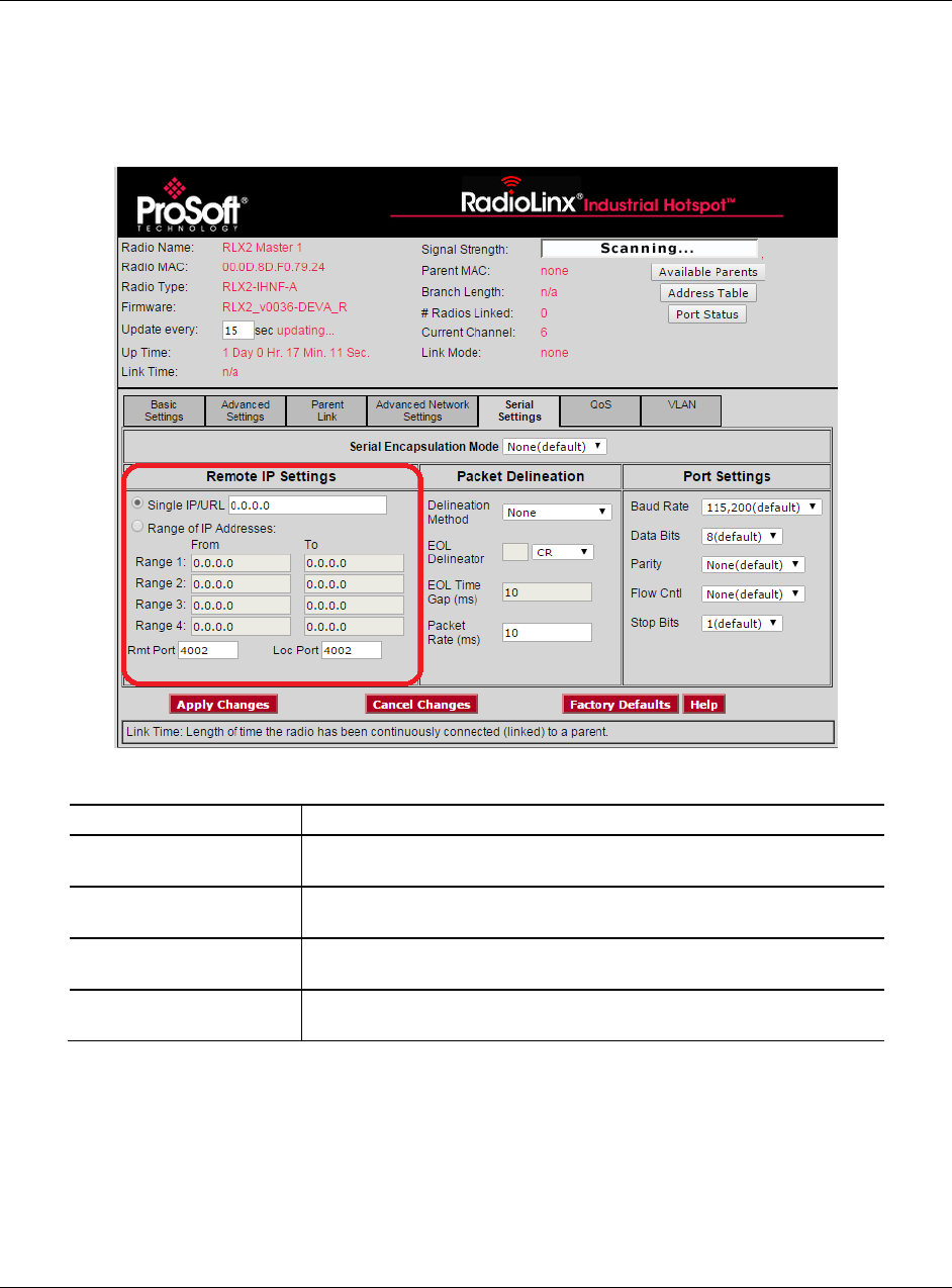
4.7.2 Remote IP Settings
You use the REMOTE IP SETTINGS parameters in the Radio Configuration /
Diagnostic Utility to specify the address and port information for the remote
radios for serial communication of your RLX2-IHx series radio.
Parameter
Description
Single IP/URL Address
Specifies the IP address or URL of the radio to receive encapsulated
serial protocol packets from this radio.
Range of IP Addresses
Specifies up to 4 IP Address ranges for radios to receive encapsulated
serial protocol packets from this radio.
Rmt Port
Specifies the remote UDP port number to use for encapsulated serial
data transmission.
Loc Port
Specifies the local UDP port number to use for encapsulated serial
data transmission.
Configuring a Radio - Detailed Configuration RLX2-IHx series ♦ 802.11a, b, g, n
User Manual Industrial Hotspots
Page 110 of 227 ProSoft Technology, Inc.
October 30, 2017
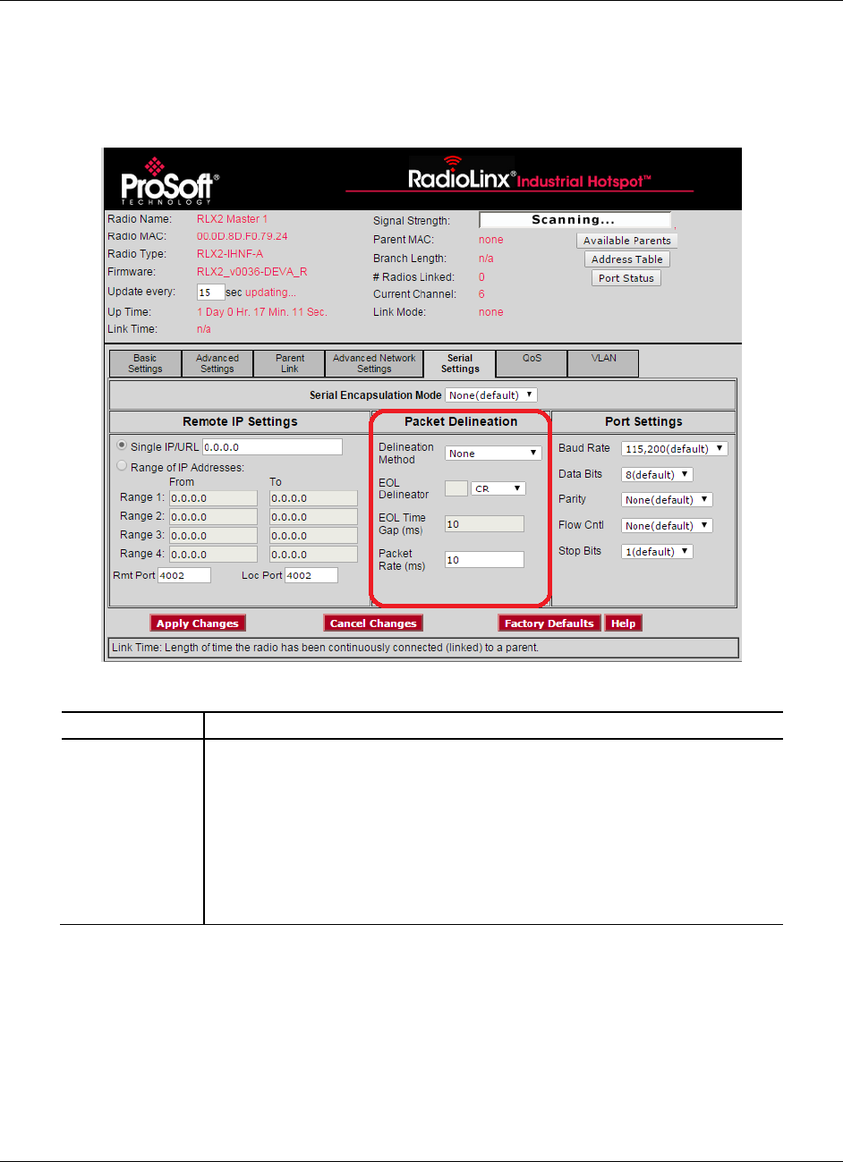
4.7.3 Packet Delineation Settings
You use the PACKET DELINEATION parameters in the Radio Configuration /
Diagnostic Utility to specify the way the radio separates serial packets for serial
communication of your RLX2-IHx series radio.
Parameter
Description
Delineation
Method
Specifies the packet separator.
TIME GAP - The radio uses a minimum time gap between characters that that
the radio interprets as a delineator for a packet. This uses the EOL TIME GAP
parameter.
NONE - The radio sends all data received between packet delineation events to
the remote radio in a single network frame.
CHARACTER - The radio uses a character sequence in the stream of characters
that indicates the delineator for the packet. This uses the EOL DELINEATOR
parameter.

RLX2-IHx series ♦ 802.11a, b, g, n Configuring a Radio - Detailed Configuration
Industrial Hotspots User Manual
ProSoft Technology, Inc. Page 111 of 227
October 30, 2017
EOL Delineator
Specifies the type of delineator the radio uses between packets when you
select CHARACTER for DELINEATION METHOD.
Type
Decimal
Hex
Description
Use Text
Any string of characters. Enter the
string of characters in the EOL
Delineator box.
CR
13
0D
Carriage Return
ESC
27
1B
Escape
LF
10
0A
Line Feed (New Line / nl)
Null
00
00
Null
Spacebar
32
20
Space
Tab
09
09
Horizontal Tab
EOL Time Gap
(milliseconds)
Specifies the time gap the radio uses between packets when you select TIME
GAP for DELINEATION METHOD. This is the length of time that must elapse after a
character is received (from the local attached device) before the radio marks
the end of a packet.
The smallest valid value for this parameter is limited by the device and is
platform dependent.
Packet Rate
(milliseconds)
Specifies the minimum time gap that the radio interprets as an inter-packet
space. When the radio detects this time gap, it defines the characters received
up to that point as a single packet and sends it to the remote radio.
Valid values are 1,000 to 500,000.
Configuring a Radio - Detailed Configuration RLX2-IHx series ♦ 802.11a, b, g, n
User Manual Industrial Hotspots
Page 112 of 227 ProSoft Technology, Inc.
October 30, 2017
4.7.4 Port Settings
You use the PORT SETTINGS parameters in the Radio Configuration / Diagnostic
Utility to specify the serial port settings of your RLX2-IHx series radio.
Parameter
Definintion
Baud Rate
Specifies the baud rate for the serial port on the radio. This must
match the baud rate setting on the connected serial device.
Data Bits
Specifies the number of data bits for the serial port on the radio. This
must match the data bits setting on the connected serial device.
Values: 5, 6, 7 or 8
Parity
Specifies the parity for the serial port on the radio. This must match the
parity setting on the connected serial device.
Values: None, Even, Odd, 1 or 0
Flow Control
Specifies the flow control (handshaking) mode for the serial port on the
radio. This must match the handshaking mode setting on the
connected serial device.
Values: None or Hardware
Stop Bits
Specifies the stop bits for the serial port on the radio. The stop bits on
the radio must match the stop bits setting on the connected serial
device.
Values: 1 or 2
RLX2-IHx series ♦ 802.11a, b, g, n Configuring a Radio - Detailed Configuration
Industrial Hotspots User Manual
ProSoft Technology, Inc. Page 113 of 227
October 30, 2017
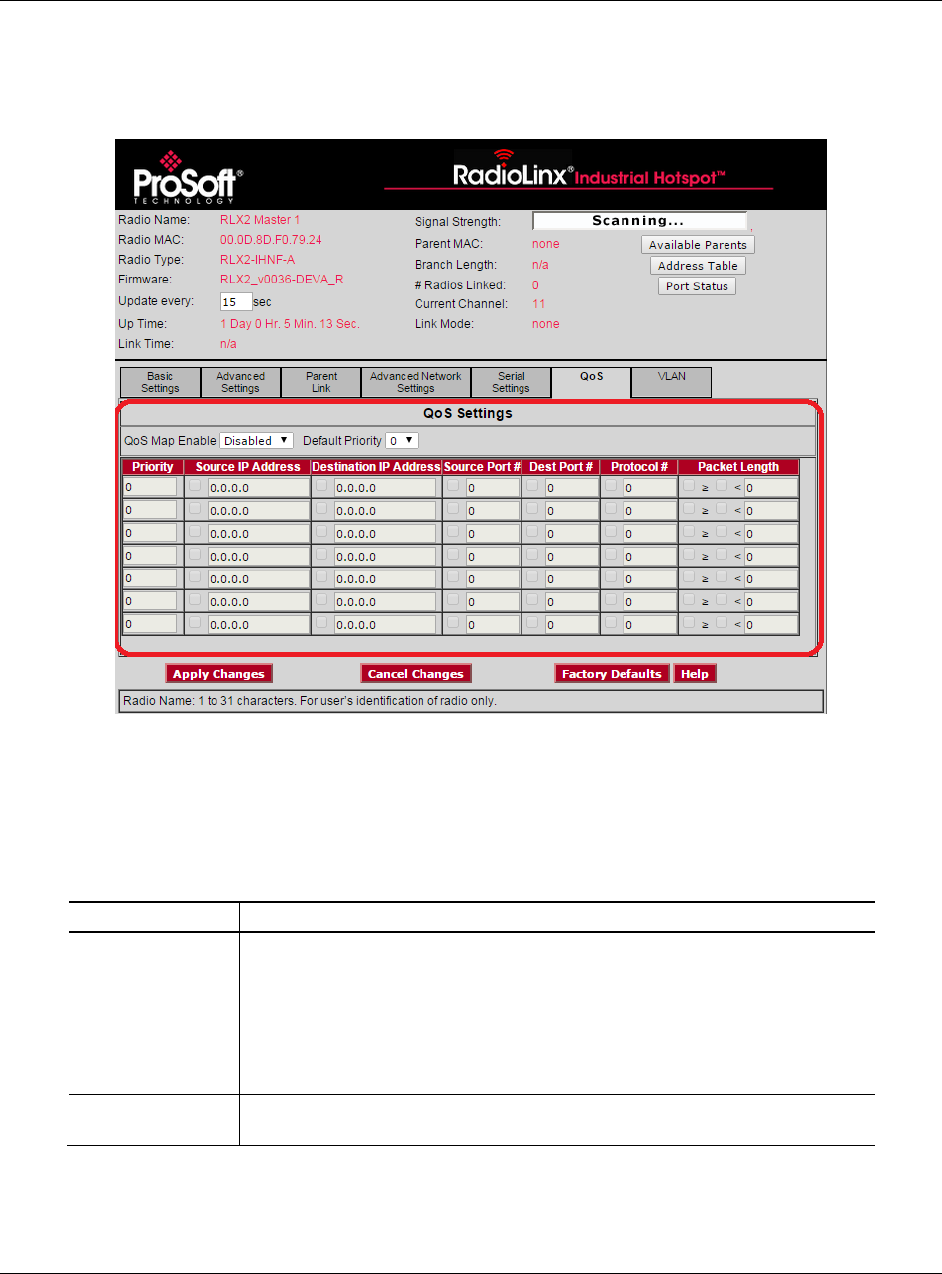
4.8 Configuring Quality of Service (QoS) Settings
You use the QOS settings tab in the Radio Configuration / Diagnostic Utility to
specify the packet priority value parameters for a RLX2-IHx series radio.
RLX2-IHx series radios always prioritize frames using QoS for packets received
already marked with a priority value. The QOS tab allows you to set the default
priority for frames that the radio receives without any priority markings. In
addition, you can map a priority value to packets received without priority
markings according to a set of matching criteria.
Parameter
Description
QoS Map Enable
Specifies whether the the RLX2-IHx series radio uses the priority mapping
function.
ENABLED - The radio uses the priority mapping table to prioritize packets
without a priority value. You must select Enabled before you can edit the QoS
Map table.
DISABLED - The radio does not set priority values for packets without a priority
value.
Default Priority
Specifies the default priority for packets received on the Ethernet interface
without a priority value (default is 0 - no priority).

Configuring a Radio - Detailed Configuration RLX2-IHx series ♦ 802.11a, b, g, n
User Manual Industrial Hotspots
Page 114 of 227 ProSoft Technology, Inc.
October 30, 2017
Parameter
Description
QoS Map Table
Specifies up to eight separate match criteria to identify and assign priority
values to received Ethernet packets. Each filter has several parameters that
you can enable by selecting the check box to the left of each parameter.
When you enable multiple parameters in a row, all enabled parameters in that
row must match before the radio assigns the specified PRIORITY value to a
packet.
PRIORITY - The priority value the radio assigns to the received Ethernet frame
if it was not already marked with a priority value and if all enabled parameters
in the same row match.
SOURCE IP ADDRESS - A parameter match occurs for all packets received from
the device with this source IP address.
DESTINATION IP ADDRESS - A parameter match occurs for all packets received
addressed to the device with this destination IP address.
SOURCE PORT NO. - A parameter match occurs for all IP packets received with
this source port value.
DEST PORT NO. - A parameter match occurs for all IP packets received with
this destination port value.
PROTOCOL NO. - A parameter match occurs for all IP packets received with this
protocol number.
PACKET LENGTH - A parameter match occurs for all iP packets received with
the correct packet length.
You must enter a packet length threshold
You must select the match criteria:
Select < to match if the length of the received packet is LESS THAN the
threshold.
Select to match if the length is GREATER THAN OR EQUAL TO the threshold.
Select both < and to match ALL PACKET LENGTHS.
RLX2-IHx series ♦ 802.11a, b, g, n Configuring a Radio - Detailed Configuration
Industrial Hotspots User Manual
ProSoft Technology, Inc. Page 115 of 227
October 30, 2017
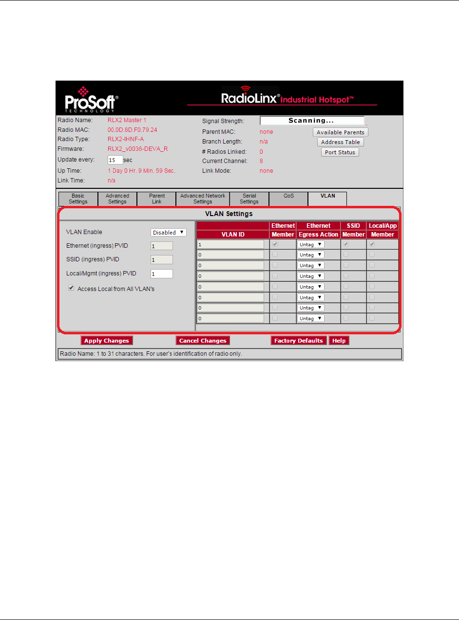
4.9 Configuring VLAN Settings
You use the VLAN tab in the Radio Configuration / Diagnostic Utility to specify
the Virtual Local Area Network parameters of a RLX2-IHx series radio. When the
radio sends a packet, it includes the selected VLAN packet ID.
RLX2-IHx series radios support port based VLANs. Each RLX2-IHx series radio
can be considered to have 3 different ports or interfaces; the Ethernet interface,
the local applications stack of the radio itself, and the 802.11 BSS created by
each radio, allowing client devices to associate. You can configure the VLAN
settings for the Ethernet interface on all RLX2-IHx series radios. You can
configure the VLAN for the Local and SSID ports on the Master radio. The
Master radio pushes these settings to each connected Repeater radio. This
allows the VLAN settings for a bridged network rooted at a Master radio to have
common settings for these two ports. This ensures, for example, that if the Local
interface is set to a management VLAN, the all Repeater radios are accessible
from a Management PC. For more information, see Appendix D - RLX2-IHx
series Virtual LAN (VLAN) Functionality (page 175).
You can think of the Ethernet ports for the Master radio and its associated
Repeater radios as a smart switch. Transporting tagged frames to the
appropriate remote Ethernet port is automatic and does not require any settings.

Configuring a Radio - Detailed Configuration RLX2-IHx series ♦ 802.11a, b, g, n
User Manual Industrial Hotspots
Page 116 of 227 ProSoft Technology, Inc.
October 30, 2017
Parameter
Description
VLAN Enable
Select this check box to enable the VLAN function of the radio.
When enabled, packets received by the radio on an interface that
are not VLAN tagged are assigned to the VLAN as set by the PVID
parameter of the respective interface.
When disabled, the radio still bridges received Ethernet packets
that are VLAN tagged but does not act on the VLAN ID of the
frame or add or remove any VLAN tags.
Ethernet (ingress) PVID
SSID (ingress) PVID
Local/Mgmt (ingress)
PVID
Specifies the PVID setting representing the VLAN ID to assign to non-
tagged ingress frames from each interface (Ethernet, SSID,
Local/Mgmt).
Access Local from all
VLANs
Select this check box to allow the Mgmt interface to be accessible from
all VLANs and interfaces (supported by the Local/Mgmt interface).
VLAN Settings
Specifies the details for each VLAN.
You use the VLAN Table to make each of the interfaces a member of a
particular VLAN ID, and specify whether frames sent from the Ethernet
interface should be tagged or untagged for a particular VLAN. You can
configure up to 10 different VLAN ID's.
VLAN ID - The ID of the VLAN to be assigned to the radio’s interfaces.
Valid VLAN ID's range from 1 to 4096. Note that VLAN ID's 1956 and
1957 are reserved and cannot be used.
ETHERNET MEMBER - Select this check box to make the Ethernet
interface of the radio a member of the VLAN indicated by the row’s
VLAN ID.
ETHERNET EGRESS ACTION - Specifies whether frames belonging to the
row’s VLAN ID are sent out the Ethernet port as TAGGED or UNTAGGED.
SSID MEMBER - Select this check box to make the SSID (BSS) of the
RLX2-IHx series a member of the VLAN indicated by the row’s VLAN
ID.
LOCAL/APP MEMBER - Select this check box to make the radio's
Local/App interface is a member of the VLAN indicated by the row’s
VLAN ID.
RLX2-IHx series ♦ 802.11a, b, g, n Using the IH Browser to Manage your Radios
Industrial Hotspots User Manual
ProSoft Technology, Inc. Page 117 of 227
October 30, 2017
5 Using the IH Browser to Manage your Radios
In This Chapter
Viewing the Radios in the IH Browser ................................................. 118
Viewing the Radio Properties .............................................................. 126
Setting the Radio IP Address in the IH Browser .................................. 128
Assigning a Temporary IP Address ..................................................... 129
Viewing Additional Data in the IH Browser .......................................... 130
Connecting to the Radio Configuration Utility ...................................... 130
Updating the Radio Firmware .............................................................. 132
Pinging Devices on the Network .......................................................... 133
Viewing Network Data in the IH Browser ............................................. 135
The RadioLinx Industrial Hotspot Browser (IH Browser) finds RLX2-IHx series
radios connected to the network. It displays the radio’s status and basic settings.
You can use the IH Browser to perform a number of tasks, including:
View all the radios connected through the
network to your PC in either a list (table) or
topology view.
Open the Radio Configuration / Diagnostic
Utility in a web browser on your PC to
configure or check diagnostics for your
radio.
Assign a temporary IP address to a radio.
Show the Event Log with a history of events
that occurred on the radio.
Update the firmware in the radio.
Send a ping command to a radio or other IP
address.
View a list of client radios.
View a list of wired Ethernet nodes
connected to the network.
View a list of all the access points detected
on the network (including those from other
vendors)
View a list of all the active interface ports on
the radio.
View the radio’s properties.
View the radio’s Event Log.
Using the IH Browser to Manage your Radios RLX2-IHx series ♦ 802.11a, b, g, n
User Manual Industrial Hotspots
Page 118 of 227 ProSoft Technology, Inc.
October 30, 2017
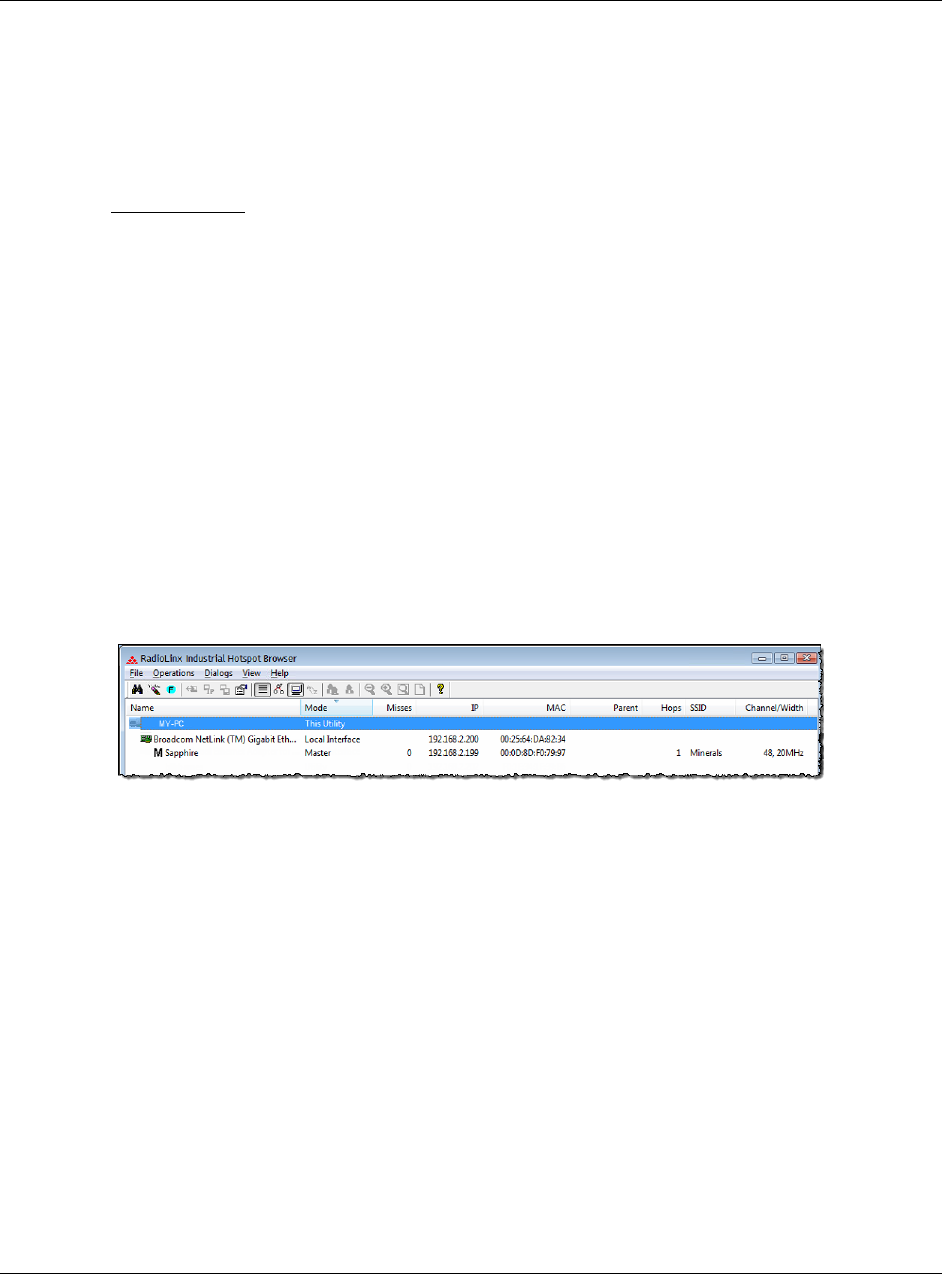
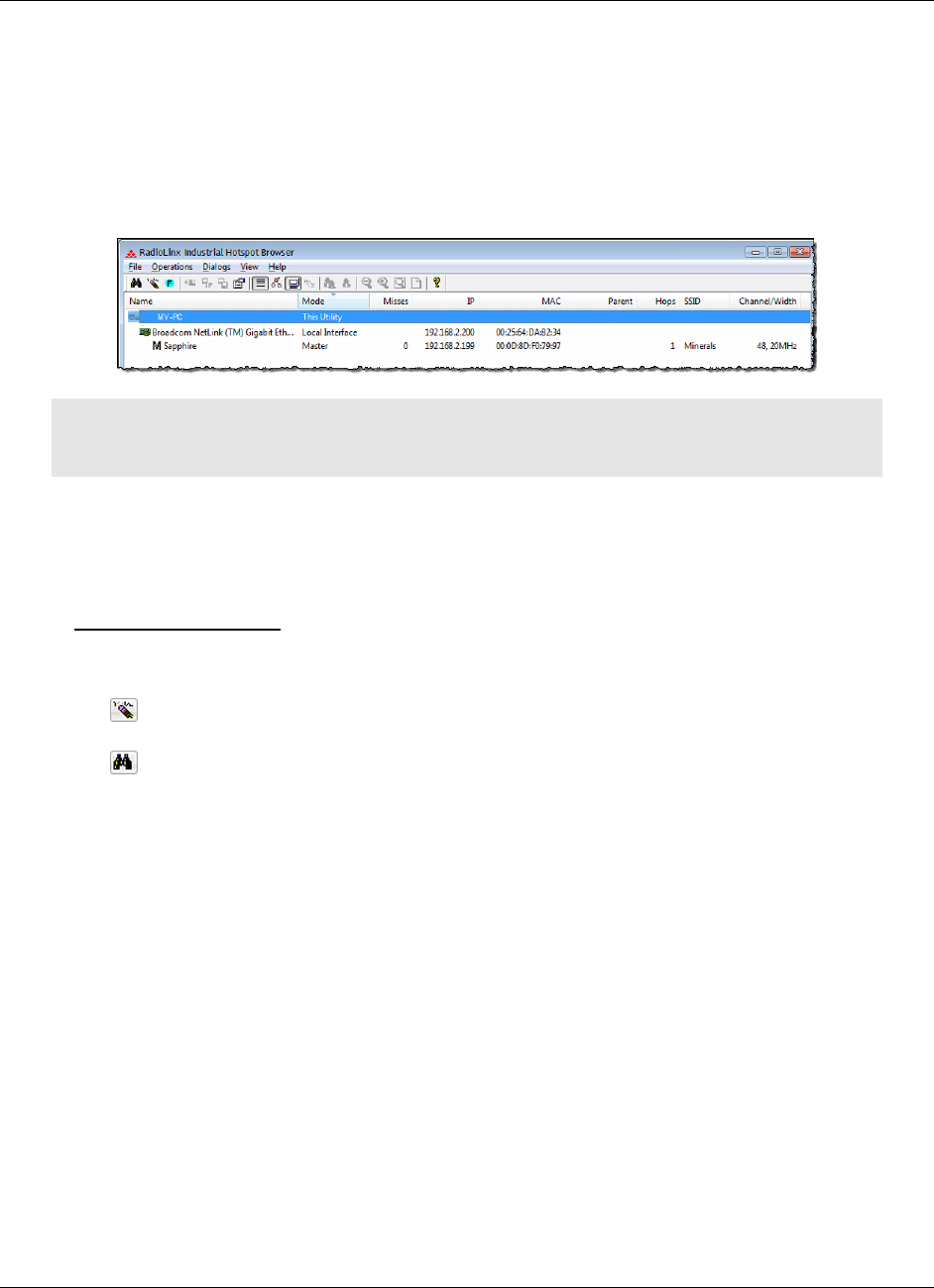
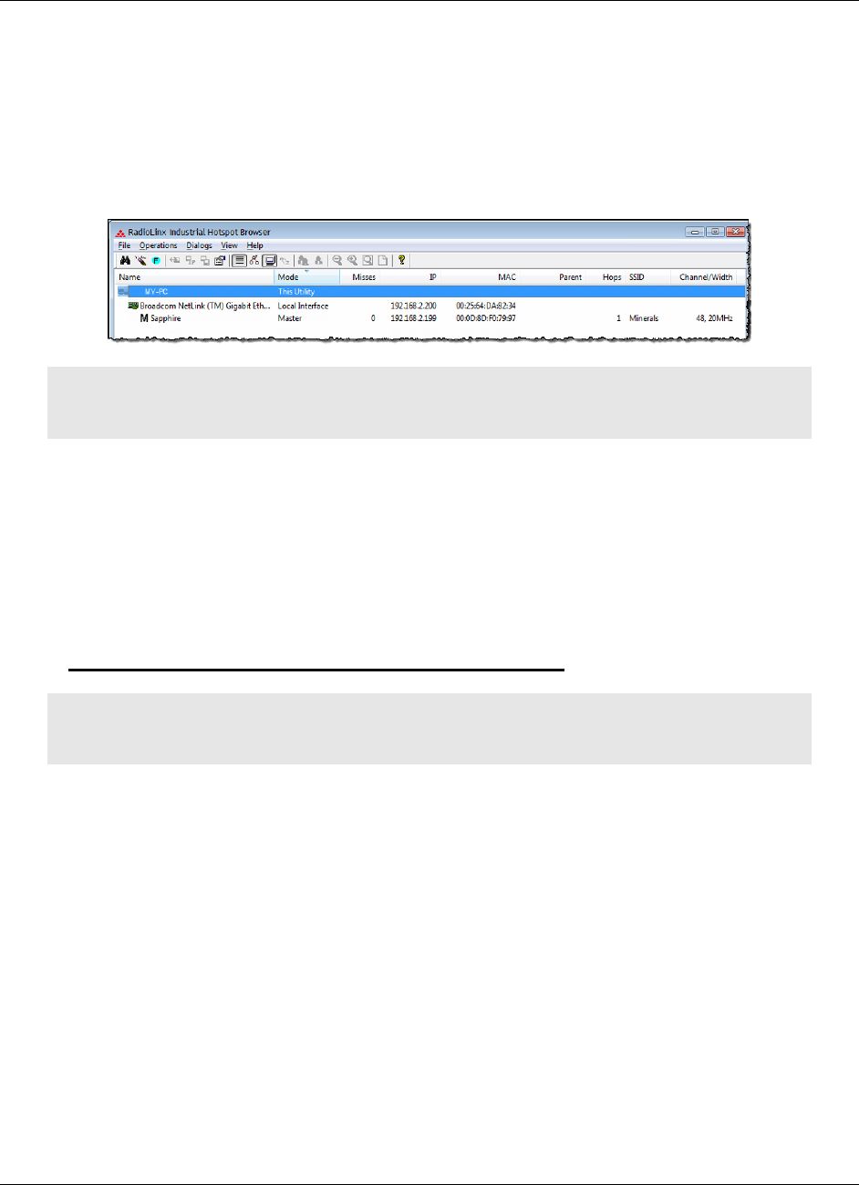
5.1 Viewing the Radios in the IH Browser
Start the IH Brower: see Starting the IH Browser (page 24). If the radio is
powered up and connected, it appears in the IH Browser. Note that the MAC
address is the same address as that of the label on the radio. The List view
(shown in the image below) displays the RLX2-IHx series radios (or previous
generation RLXIB radios, except the RLCIB-IHN) on the same network as the
computer running the IH Browser.
Note: You can perform many common tasks by right-clicking on the radio and choosing a
command.
5.1.1 Refreshing the Display in the IH Browser
To refresh the display
If you have made changes to a radio's configuration, refresh the IH Browser by
clearing and scanning the display using the buttons on the toolbar.
The Erase button clears the radios from display (or from the FILE menu
choose CLEAR).
The Scan button rescans the network for RLX2-IHx series radios (or from
the FILE menu choose SCAN).
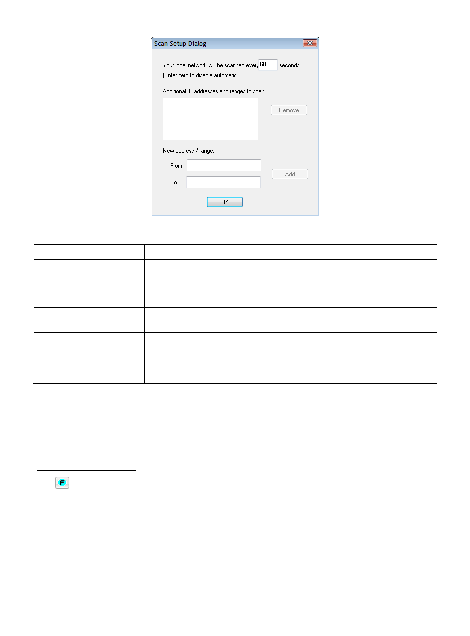
5.1.2 Defining the Scan Parameters in the IH Browser
You use the Scan Setup dialog box to specify how the IH Browser refreshes the
display when scanning the network. By default, the program sends a broadcast
Scan message to all the radios at the same time, then waits for them to respond.
Broadcasts are limited to a local network, and will not be passed through a
router.
If there is a router between the PC running the IH Browser and the radio, enter
the IP address of a single radio or the range of IP addresses of multiple radios.
This adds them to the IP addresses the IH Browser scans.
RLX2-IHx series ♦ 802.11a, b, g, n Using the IH Browser to Manage your Radios
Industrial Hotspots User Manual
ProSoft Technology, Inc. Page 119 of 227
October 30, 2017
To define the scan parameters, from the FILE menu, choose SCAN SETUP.
Parameter
Description
Local network scanning
interval
Specifies how often the IH Browser scans the network before updating
the display.
Enter zero to disable automatic scanning. You can still scan the network
manually. See Refreshing the Display in the IH Browser (page 42).
Additional IP addresses
Displays the IP addresses the IH Browser scans at the scanning
interval.
Remove
Removes the selected IP address or range. Click on an IP address or
address range to select it.
New Address / Range
Enter the new IP address (in FROM) or range of IP addresses (in FROM
and TO) and then click ADD.
5.1.3 Freezing the Display in the IH Browser
Freezing the display in the IH Browser prevents it from updating with new data.
To freeze the display
The Freeze button on the IH Browser toolbar prevents the display from
updating (or from the FILE menu choose FREEZE).
Click the Freeze button again to start updating the display.

Using the IH Browser to Manage your Radios RLX2-IHx series ♦ 802.11a, b, g, n
User Manual Industrial Hotspots
Page 120 of 227 ProSoft Technology, Inc.
October 30, 2017
5.1.4 Changing IH Browser Columns in List View
You can change the columns that appear in the IH Browser main window in List
View.
To change the columns in the IH Browser window
1 From the VIEW menu, click SELECT COLUMNS.
2 In the Select Columns dialog box, click the check boxes for the columns you
want to appear in the window.
To reset the columns in the IH Browser window to the default
From the VIEW menu, click RESET COLUMNS.
5.1.5 Switching between List and Topology Views
You can switch between the List and Topology Views in the IH Browser main
window.
The List View is the default view, and shows a list of all the connected radios
in a grid, similar to a spreadsheet.
The Topology View shows a diagram of the network’s wireless connections. If
a radio does not appear in the view, it is not connected to the network. The
Topology View is display-only. If you want to change the way a radio is linked
to the network, see Configuring Parent Link Settings (page 94).
To switch between the List and Topology views
The List View button switches to the List View (or from the VIEW menu
choose LIST VIEW). For a description of the available columns, see List View
Columns (page 121).
The Topology View button switches to the Topology View (or from the
VIEW menu choose TOPOLOGY VIEW). For a description of the Topology View,
see Topology View Description (page 124).
To change the columns in the List View
To resize a column, click between column headers and drag to the left or
right.
To re-order the columns, click a column header and drag it to the left or right.
To sort the radios, click a column header to change the sort order
To change the displayed columns, from the VIEW menu choose SELECT
COLUMNS.
To zoom in and out in the Topology View
The Zoom In button magnifies the Topology View (or from the VIEW menu
choose ZOOM IN).
The Zoom Out button shrinks the Topology View (or from the VIEW menu
choose ZOOM OUT).
RLX2-IHx series ♦ 802.11a, b, g, n Using the IH Browser to Manage your Radios
Industrial Hotspots User Manual
ProSoft Technology, Inc. Page 121 of 227
October 30, 2017
The Zoom to Fit button resizes the Topology View to fit the window (or
from the VIEW menu choose ZOOM TO FIT).
To sort radios alphabetically in the Topology View
The Sort Alphabetically button sorts the radios in the by name Topology
View (or from the VIEW menu choose SORT ALPHABETICALLY).
To change a radio's configuration in either view
Double-click a radio to start the Radio Configuration / Diagnostic Utility for the
radio. See Connecting to the Radio Configuration Utility (page 44).
List View Columns
This topic describes the available columns in the List View. See Switching
between List and Topology Views (page 120) for more information on the List
View columns.
Note: You can display most of the same information for the radio in the Detailed Information dialog
box the IH Browser. See Viewing the Radio Properties (page 126).
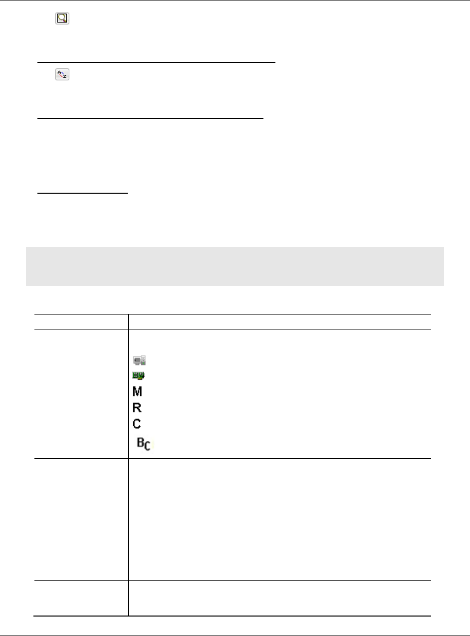
Column Name
Description
Name
Displays the devices in the IH Browser. Names appear in a nested tree
order. The icons on some entries help identify the type of device.
Computer
Wired Network Interface
Master Radio
Repeater Radio
Client Radio
Bridging Client Radio
Mode
Displays a text description of the devices in the IH Browser.
THIS UTILITY - This instance of the IH Browser.
UTILITY - Other instances of IH Browsers running on other systems on the
same network.
LOCAL INTERFACE - A network interface detected on the computer running
this instance of the IH Browser.
MASTER - A radio on the network in Master mode.
ETHERNET CLIENT - A radio on the network in Client mode
BRIDGING CLIENT - A radio on the network in Bridging Client mode.
REPEATER - A radio in the network in Repeater mode.
MAC
Displays the physical Media Access Control (MAC) address of the
devices. All ProSoft Technology devices have a MAC address in the form
00:0D:8D:XX:YY:ZZ.

Using the IH Browser to Manage your Radios RLX2-IHx series ♦ 802.11a, b, g, n
User Manual Industrial Hotspots
Page 122 of 227 ProSoft Technology, Inc.
October 30, 2017
IP
Displays the IP addresses assigned to the devices.
Mask
Displays the network mask for the device.
Gateway
Displays the IP address of the network gateway for the device.
SSID
Displays the Service Set Identifier (SSID). This is a name assigned to a
wireless network device. Repeater and Client radios must be configured
with the same SSID to connect. Note that Master radios typically
broadcast their SSID. However, you can disable SSID broadcasting so
that other wireless devices cannot detect the Master radio, If a Master is
not broadcasting its SSID, this field includes the word HIDDEN along with
the SSID of the radio; for example ProSoft/hidden.
Connection
Displays the connection state for a Repeater radio.
SCANNING - The radio is searching for a Master radio.
CONNECTED - The radio is linked to a Master radio.
Signal (dBm)
Displays the signal strength, in dBm of a Repeater or Client radio’s link to
a Master device. Master devices do not report signal strength.
Hops
Displays the number of wireless connections from the device to the wired
connection of a Master. This value is always 1 for a Master radio. For
Repeater radios, the value is at least 2, but can be higher if there are more
hops to the Master radio. Client radio do not display a hop value.
Parent
Displays the MAC address of the Parent radio to which this Repeater or
Client radio is linked. This is blank for Master devices.
Associations
Displays the number of non-bridge wireless connections to this radio.
Client or Bridging Client radios that are connected always show 1 in this
column (and 0 in the Bridges column).
Bridges
Displays the number of non-bridge wireless connections to this radio.
Client or Bridging Client radios that are connected always show 1 in this
column (and 0 in the Bridges column).
Tx (kbits/sec)
Displays a moving average of transmit throughput in kilobits/second. It
does not count packet overhead, and only counts payload data. For
Repeater radios, this shows the throughput only for the radio link to the
Parent radio. For Master radios, this is the throughput sum of all the
Master's radio links.
Rx (kbits/sec)
Displays a moving average of receive throughput in kilobits/second. It
does not count packet overhead, and only counts payload data. For
Repeater radios, this shows the throughput only for the radio link to the
Parent radio. For Master radios, this is the throughput sum of all the
Master’s radio links.
FW Ver
Displays the firmware version number.
For IH Browser entries, this is the version of the IH Browser itself.
For radios, this is the version of the firmware code in the radio. This is
not the version of the image file installed into the radio (for that
information see IMAGE VER described below).
Boot Ver
Displays the boot loader code version number.
For IH Browser entries, this is the version of the network
communication engine in the IH Browser (e.g. WinXP, WinVista).
For radios, this is the version of the boot loader code in the radio.
Image
Displays the type of the firmware image that the radio is currently running
(PRIMARY or SECONDARY). Each radio has two copies of operating firmware
installed, and the radio will automatically switch from one to the other if
one of them becomes corrupted.

RLX2-IHx series ♦ 802.11a, b, g, n Using the IH Browser to Manage your Radios
Industrial Hotspots User Manual
ProSoft Technology, Inc. Page 123 of 227
October 30, 2017
Compression
Displays the compression state of the firmware images in the radio
(COMPRESSED or UNCOMPRESSED).
Ethernet
Displays the Ethernet status for the radio.
ATTACHED - The radio is connected to a wired Ethernet network.
DETACHED - The radio is not connected to a wired Ethernet network.
Channel/Width
Displays the operating channel and channel width. The width value is
always 20MHz except on 802.11n devices where it can be 20MHz or
40MHz.
Example: 48, 20 MHZ for channel 48 with a 20 MHz channel width.
Security
Displays the encryption type setting for the radio. Some valid settings are
AES, TKIP, AES&TKIP, WEP128 TKIP, WEP128, WEP64.
Misses
Displays the number of times the IH Browser has failed to receive a
response from the device after a scan. Ideally this number should always
be zero.
RSTP
Displays the setting for RSTP in the radio (ENABLED, DISABLED, and STP).
The STP state is a legacy "non-rapid" Spanning Tree mode that the radio
automatically uses if it detects a peer wired bridge in STP mode. All radios
on a network must have the same RSTP state to link properly.
Link Time
Displays the link time of the device; for example 24d,13h,10m,32s. This
time resets to zero on a Roam, or if the link is dropped and re-established
with the same Parent radio.
TX Rate
Displays the current modulation data rate that the radio is using for
transmission. This may be slower than the configured nominal rate
because of retries or other environmental factors.
For 802.11a/b/g devices, the data rate is expressed in kilobits or
megabits per second (for example, 54Mb/s).
For 802.11n devices, the data is expressed in MCS rates from 0 to 15
(for example, MCS7).
Temperature
Displays the internal temperature of the radio as measured on the circuit
board in degrees Celsius. Note that internal measured temperature always
exceeds the ambient external temperature.
Retries(%)
Displays the ratio of packet re-transmission to total packet transmissions
during the last five-second interval for the radio.
Uptime
Displays the amount of time the radio has been running since the last
power cycle or reset; for example, 1d,4h,13m,25s.
Product
Displays the model number of the RLX2 radio; for example RLX2-IHA,
RLX2-IHG, RLX2-IHFN, RLX2-IHFN-W, or RLX2-IHW.
Image Ver
Displays the name of the image file loaded into the radio; for example,
RLX2_V0036_R. It matches the Firmware label displayed for the radio in
the Radio Configuration / Diagnostic Utility.
Using the IH Browser to Manage your Radios RLX2-IHx series ♦ 802.11a, b, g, n
User Manual Industrial Hotspots
Page 124 of 227 ProSoft Technology, Inc.
October 30, 2017
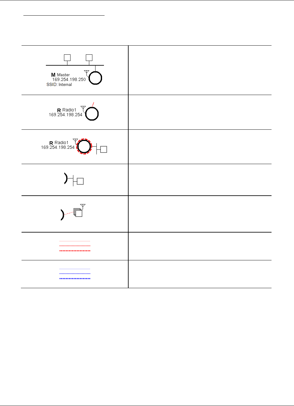
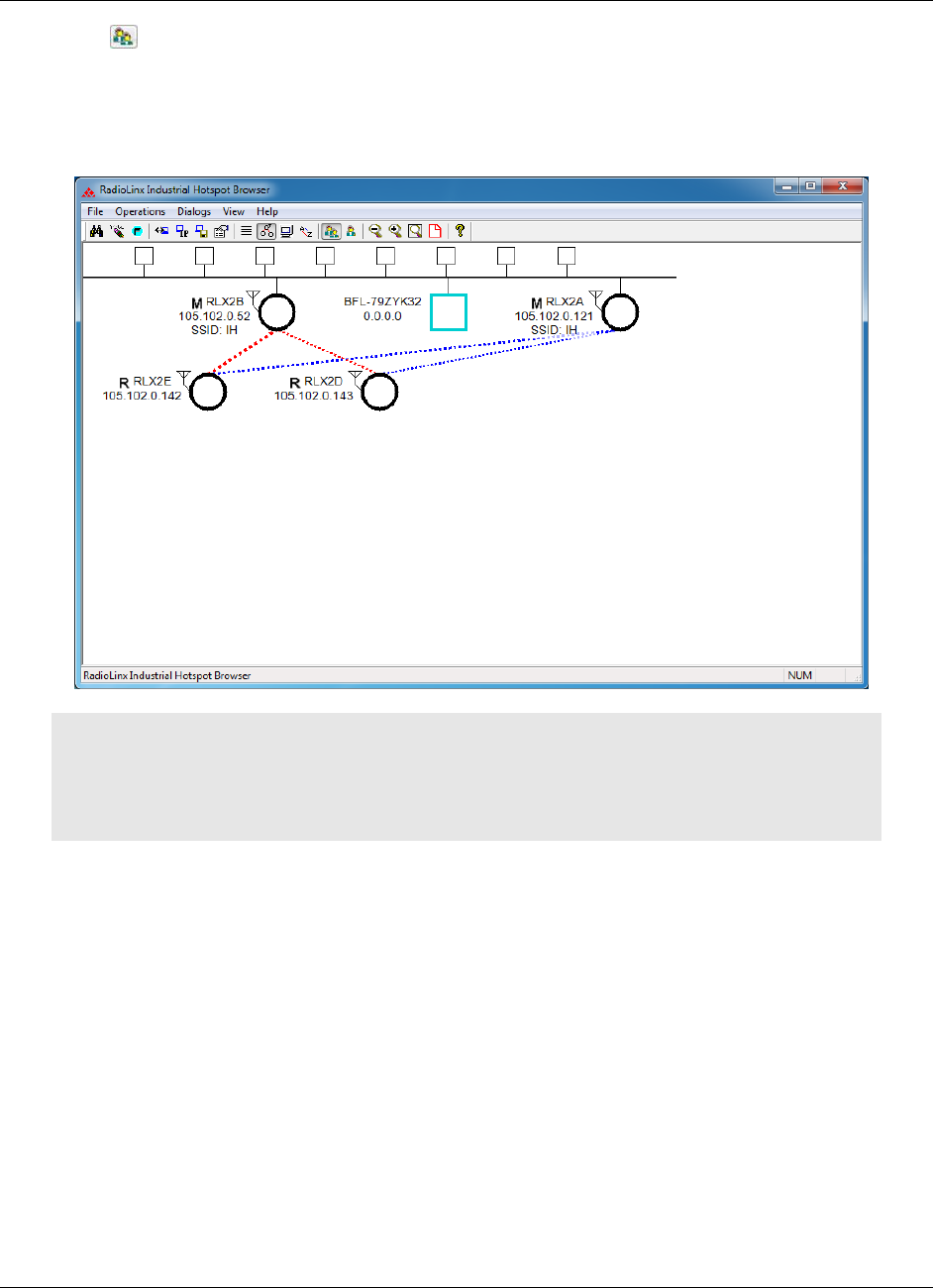
Topology View Description
This topic describes the Topology View. See Switching between List and
Topology Views (page 120) for more information on the Topology View.
Indicates the Master radio; always shown at the top,
Indicates a radio linked to the network
Indicates a radio not linked to to a Parent radio, but on
the same network as the computer hosting the IH
Browser.
Indicates that an Ethernet connection exists to the
radio, but does not indicate the number of devices on
the connection
Indicates that wireless clients (such as laptops and
tablet computers) are linked to this radio. The number
of clients linked is indicated by the number of boxes
and/or a number.
Indicates signal strength between radios. The width of
the line is not calibrated, but a wider line indicates a
relatively stronger signal strength.
Indicates links to alternate Parent radio candidates that
could be chosen if the current Parent link drops or
degrades.
RLX2-IHx series ♦ 802.11a, b, g, n Using the IH Browser to Manage your Radios
Industrial Hotspots User Manual
ProSoft Technology, Inc. Page 125 of 227
October 30, 2017
5.1.6 Printing the View in the IH Browser
You can print the current view in the IH Browser.
To print the current view, from the FILE menu choose PRINT.
To define the page orientation, paper source, and size, from the FILE menu
choose PRINT SETUP.
To preview the printed view, from the FILE menu choose PRINT PREVIEW. This
can help you adjust the view in the IH Browser so it does not break across
pages when printed.
In the Topology View, to display a border around the area to be printed, do
one of the following:
o From the VIEW menu, choose PRINT AREA.
o On the IH Browser toolbar click the Show Page Outline button.
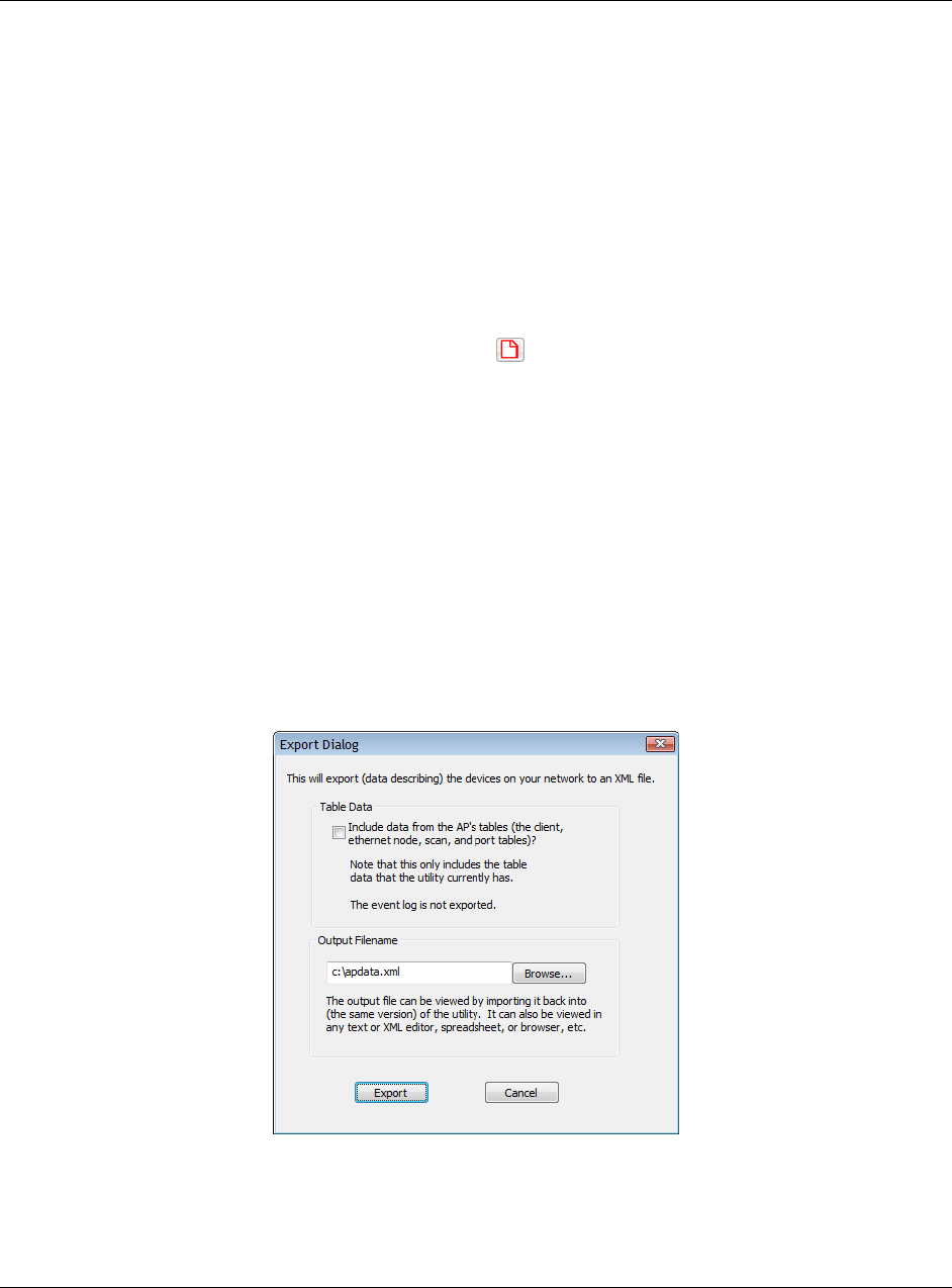
5.1.7 Importing and Exporting IH Browser Data
You can export data from, and import data into, the IH Browser. Exporting data
creates and saves an XML file containing the current configuration and status of
all radios discovered by the IH Browser. You can use this command under the
direction of ProSoft Technical Services, for troubleshooting purposes. Importing
data brings in the data from a previously created IH Browser XML file.
To export data from the IH Browser, from the FILE menu choose EXPORT.
You can choose to include the data from the current Wireless Client, Ethernet
Nodes, Scan List, and Port Table tables. See Viewing Additional Data in the
IH Browser (page 130) for information about those tables.
To import data from an export file created in the IH Browser, from the FILE
menu choose IMPORT.
Using the IH Browser to Manage your Radios RLX2-IHx series ♦ 802.11a, b, g, n
User Manual Industrial Hotspots
Page 126 of 227 ProSoft Technology, Inc.
October 30, 2017
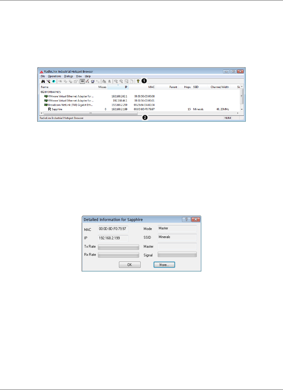
5.1.8 Hiding the Toolbar and Status Bar in the IH Browser
You can hide and display the Toolbar and Status bar in the IH Browser window.
To hide and show the Toolbar (1 in the image below), from the VIEW menu
choose TOOLBAR.
To hide and show the Status Bar (2 in the image below), from the VIEW menu
choose STATUS BAR.
5.2 Viewing the Radio Properties
The Detailed Information dialog box shows information about the currently
selected radio.
1 In the IH Broswer, select (click) a radio in either the List View or Topology
View.
2 From the DIALOGS menu choose PROPERTIES, or right-click the radio and
choose PROPERTIES.
RLX2-IHx series ♦ 802.11a, b, g, n Using the IH Browser to Manage your Radios
Industrial Hotspots User Manual
ProSoft Technology, Inc. Page 127 of 227
October 30, 2017
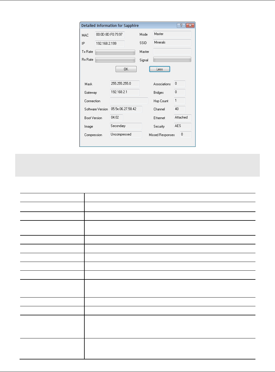
3 Click MORE to display more information.
Note: You can display most of the same information in the List View in the IH Browser. See List
View Columns (page 121).
Parameter
Description
MAC
Displays the MAC address of the selected radio.
IP
Displays the IP address of the selected radio.
Mode
Displays the mode of the selected radio (MASTER, REPEATER, CLIENT,
BRIDGING CLIENT)
SSID
Displays the SSID of the selected radio.
TX Rate
Displays a green bar when there is transmit activity.
RX Rate
Displays a green bar when there is receive activity.
Master
Displays the MAC address of the radio's current Master radio.
Signal
Displays a green bar when there is a signal.
More / Less
Click MORE to expand the dialog box and display more information.
Click LESS to reduce the dialog box and display less information.
Mask
Displays the network mask for the current radio.
Gateway
Displays the network gateway IP for the current radio.
Connection
Displays the connection state for a Repeater radio.
SCANNING - The radio is searching for a Master radio.
CONNECTED - The radio is linked to a Master radio.
Software Version
Displays the version of the firmware code in the radio. This is not the
version of the image file installed into the radio (for that information see
IMAGE described below).

Using the IH Browser to Manage your Radios RLX2-IHx series ♦ 802.11a, b, g, n
User Manual Industrial Hotspots
Page 128 of 227 ProSoft Technology, Inc.
October 30, 2017
Parameter
Description
Boot Version
Displays the boot loader code version number. This is the version of the
boot loader code in the radio.
Image
Displays the type of the firmware image that the radio is currently
running (PRIMARY or SECONDARY). Each radio has two copies of
operating firmware installed, and the radio will automatically switch from
one to the other if one of them becomes corrupted.
Compression
Displays the compression state of the firmware images in the radio
(COMPRESSED or UNCOMPRESSED).
Associations
Displays the number of non-bridge wireless connections to this radio.
Client or Bridging Client radios that are connected always show 1 in this
column (and 0 in the Bridges column).
Bridges
Displays the number of non-bridge wireless connections to this radio.
Client or Bridging Client radios that are connected always show 1 in this
column (and 0 in the Bridges column).
Hop Count
Displays the number of wireless connections from the device to the
wired connection of a Master. This value is always 1 for a Master radio.
For Repeater radios, the value is at least 2, but can be higher if there
are more hops to the Master radio. Client radio do not display a hop
value.
Channel
Displays the operating channel for radio.
Ethernet
Displays the Ethernet status for the radio.
ATTACHED - The radio is connected to a wired Ethernet network.
DETACHED - The radio is not connected to a wired Ethernet network.
Security
Displays the encryption type setting for the radio. Some valid settings
are AES, TKIP, AES&TKIP, WEP128 TKIP, WEP128, WEP64.
Missed Responses
Displays the number of times the IH Browser has failed to receive a
response from the device after a scan. Ideally this number should
always be zero.
5.3 Setting the Radio IP Address in the IH Browser
To set the radio IP address
If the radio is on a network with a DHCP server, it gets an IP address through
DHCP.
If the radio is not on a network with a DHCP server, the radio appears with an
IP address of 0.0.0.0. You can assign a temporary IP address to assist with
configuring the radio. See Assigning a Temporary IP Address (page 42).
RLX2-IHx series ♦ 802.11a, b, g, n Using the IH Browser to Manage your Radios
Industrial Hotspots User Manual
ProSoft Technology, Inc. Page 129 of 227
October 30, 2017
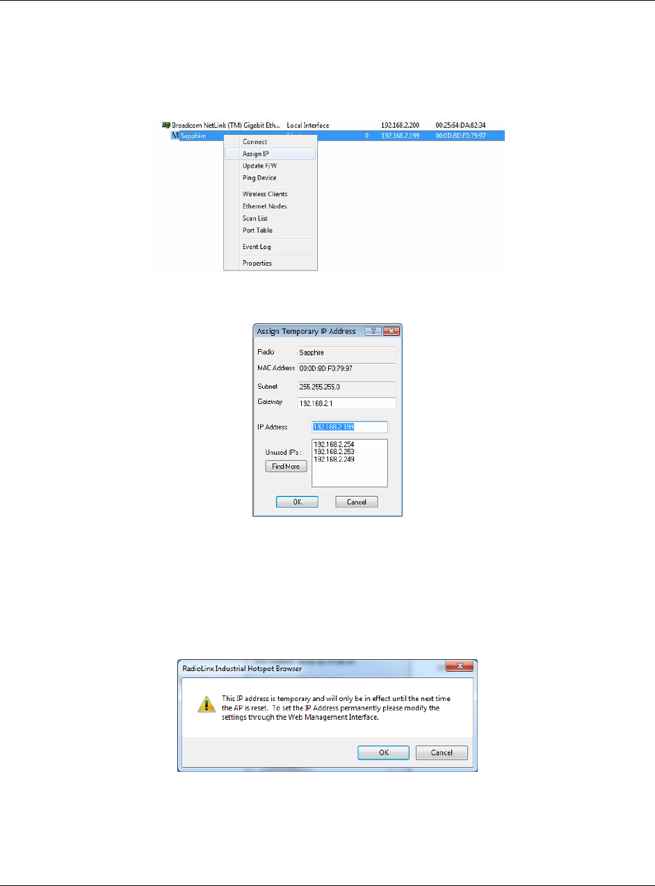
5.4 Assigning a Temporary IP Address
A temporary IP address allows you to access and configure a radio using the IH
Browser and the Radio Configuration / Diagnostic Utility.
1 In the IH Browser, right-click the radio and then click ASSIGN IP.
This opens the Assign Temporary IP Address dialog box.
The UNUSED IP’S list are the IP addresses that are currently available on the
network.
2 The IH Browser suggests the network parameters for the temporary IP
address. It queries the IP addresses, and displays them if it does not receive
a response. Click one of the unused IP's, or enter an unused IP address, and
click OK. The IH Browser warns you that the IP address is temporary.
3 Click OK and refresh the display in the IH Browser. Your radio should now
appear in the IH Browser window with the temporary IP address.
4 To set a permanent IP address for the radio, see Configuring a Radio -
Getting Started (page 44).
Using the IH Browser to Manage your Radios RLX2-IHx series ♦ 802.11a, b, g, n
User Manual Industrial Hotspots
Page 130 of 227 ProSoft Technology, Inc.
October 30, 2017
5.5 Viewing Additional Data in the IH Browser
Start the IH Brower (see Starting the IH Browser (page 24)). If the radio is
powered up and connected, it appears in the IH Browser. Note that the MAC
address is the same address as that of the label on the radio. The List view
(shown in the image below) displays the RLX2-IHx series radios (or previous
generation RLXIB radios, except the RLCIB-IHN) on the same network as the
computer running the IH Browser.
Note: You can perform many common tasks by right-clicking on the radio and choosing a
command.
5.6 Connecting to the Radio Configuration Utility
This section describes how to connect to the Radio Configuration / Diagnostic
Utility using a web browser such as Internet Explorer or Firefox on your PC or
other network-enabled device.
To connect to the Radio Configuration / Diagnostic Utility
Important: Your computer or other device must be connected to the same network as the RLX2-
IHx series radio.
1 Open the Radio Configuration / Diagnostic Utility for the radio. You can do
this in any of three ways:
o In the IH Browser List view or Topography view, right-click the radio and
then click CONNECT.
o In the IH Browser List view or Topography view, double-click the radio.
o Open a web browser on your PC, and then in the address bar, type
http://, followed by the IP address for the radio, and then press ENTER.
For example, http://192.168.6.10.
RLX2-IHx series ♦ 802.11a, b, g, n Using the IH Browser to Manage your Radios
Industrial Hotspots User Manual
ProSoft Technology, Inc. Page 131 of 227
October 30, 2017
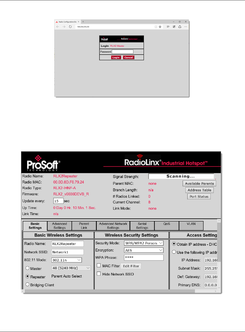
The login screen appears in the web browser.
2 Enter the password and then click LOGIN. The default password is password.
If you have lost the password for the radio, you can reset the radio to its
default settings. See Resetting a RLX2-IHx series Radio (page 148).
This opens the Radio Configuration / Diagnostic Utility for the radio. Note that
some parameters may be different from the image depending on your specific
radio model.
Using the IH Browser to Manage your Radios RLX2-IHx series ♦ 802.11a, b, g, n
User Manual Industrial Hotspots
Page 132 of 227 ProSoft Technology, Inc.
October 30, 2017
Tip: You can display the help topic for any parameter in the Radio Configuration / Diagnostic Utility
by clicking the parameter name. The parameter name turns blue when you move the cursor over a
parameter with a help topic. There is also a short description of the cursored control at the bottom
of the window.
5.7 Updating the Radio Firmware
From time to time, ProSoft Technology may release new firmware for the RLX2-
IHx series radio that may include new features and corrected anomalies. We
recommend that all RLX2-IHx series radios in a network use the same firmware
version. If your network has a mix of RLX2-IHx series models, you can load the
same firmware image file into each of them.
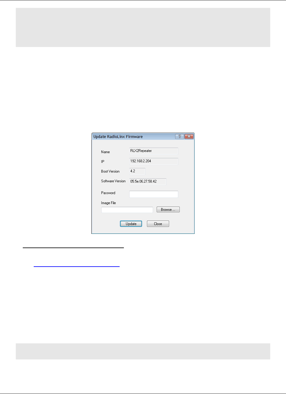
To update the firmware in the radio
1 Download the radio firmware image from the Prosoft Technology web site at
www.prosoft-technology.com and save it to a known location (such as the
Windows Desktop).
2 Start the IH Browser and click on an RLX2-IHx series radio to select it.
3 From the OPERATIONS menu choose UPDATE FIRMWARE. You can also right-
click the radio and choose UPDATE F/W.
4 Enter the password for the radio. This is the same password that you use to
log into the radio when you start the Radio Configuration / Diagnostic Utility.
See Connecting to the Radio Configuration Utility (page 44).
5 Click BROWSE to locate the firmware image file to load.
6 Click UPDATE to begin copying the new firmware to the radio.
Important: Do not turn off power to the radio during this operation.
RLX2-IHx series ♦ 802.11a, b, g, n Using the IH Browser to Manage your Radios
Industrial Hotspots User Manual
ProSoft Technology, Inc. Page 133 of 227
October 30, 2017
5.8 Pinging Devices on the Network
You can use the Ping command to test the latency of the network link between
the PC running the IH Browser and any other PC that is also running the IH
Browser (called Ping Stations).
Note: Currently there is no location information when a ping station responds to an IH Browser
scan, therefore, all Ping stations are shown connected to the top main network. It is also possible
to select an RLX2-IHx series and start a Ping Session with it.
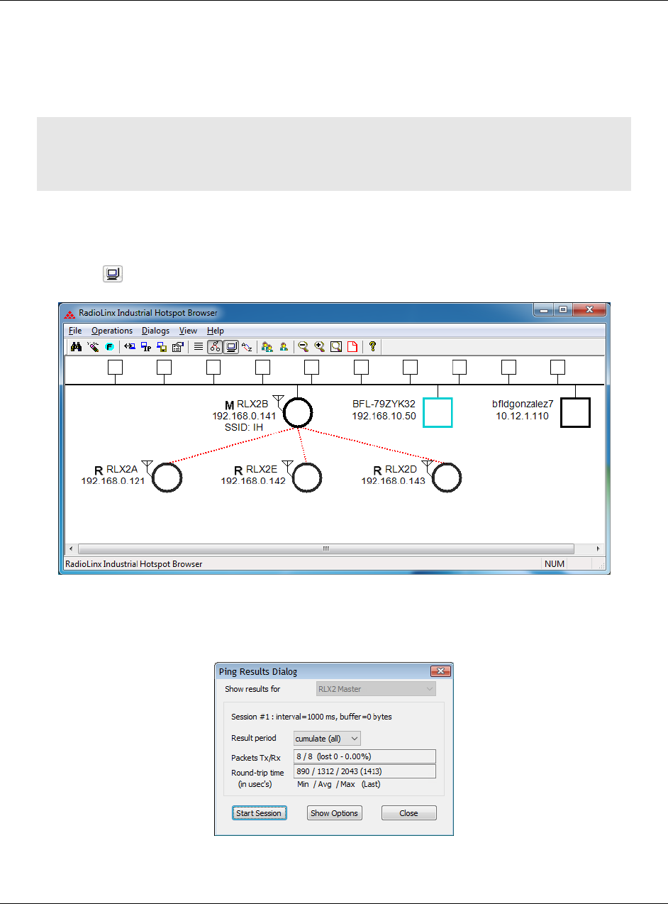
1 Start the IH Browser on your computer.
2 To start the ping session, do one of the following:
o From the VIEW menu choose SHOW PING STATIONS.
o Click the Show Browsers button on the toolbar.
3 Click (highlight) one of the other computers visible in the IH Browser.
4 From the OPERATIONS menu choose PING DEVICE to open the Ping Results
Dialog box.
Using the IH Browser to Manage your Radios RLX2-IHx series ♦ 802.11a, b, g, n
User Manual Industrial Hotspots
Page 134 of 227 ProSoft Technology, Inc.
October 30, 2017
This dialog box displays statistics on the minimum, maximum and average
latency between two points on the network.
5 Click SHOW OPTIONS to change the Ping parameters. See Ping Options
Dialog Box (page 134).
Note: If there is no PC with an IH Browser behind a remote RLX2-IHx series radio, you can select
and ping the radio itself to text its wireless link.
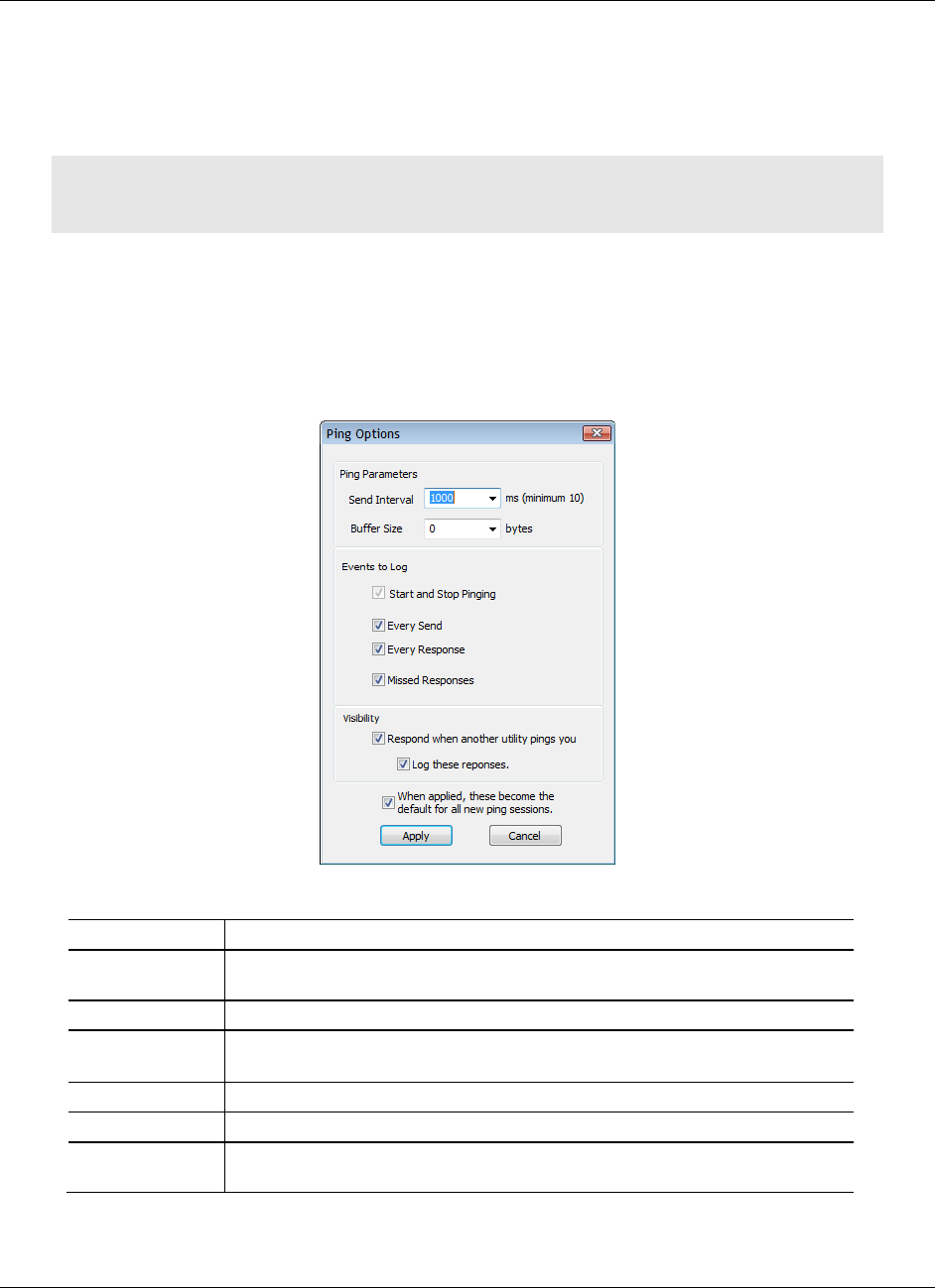
5.8.1 Setting the Ping Parameters
Use the Ping Options dialog box to choose Ping parameters, logging options,
and response to other stations. For more information, see Pinging Devices on the
Network (page 133).
Parameter
Description
Send Interval
Specifies the time between ping signals in milliseconds. The minimum interval
is 10 ms.
Buffer Size
Specifies the buffer size in bytes (the number of bytes sent on the ping).
Start and Stop
Pinging
Select this check box to log the beginning and ending of the ping session.
Every Send
Select this check box to log every ping signal sent.
Every Receive
Select this check box to log every ping response received.
Missed
Responses
Select this check box to log every missed ping response (when a device does
not respond to a ping signal.

RLX2-IHx series ♦ 802.11a, b, g, n Using the IH Browser to Manage your Radios
Industrial Hotspots User Manual
ProSoft Technology, Inc. Page 135 of 227
October 30, 2017
Respond when
another utility
pings you
Select this check box to reply to a ping request from another device.
Log these
responses
Select this check box to log each ping response sent to another device.
When applied,
these become the
default for all new
ping sessions
Select this check box to use these settings for all future ping sessions with
any device.
5.9 Viewing Network Data in the IH Browser
The IH Browser DIALOGS displays four dialog boxes that allow you to monitor the
network connections for the selected radio in either the List View or Topology
View. The four dialog boxes show:
The Wireless clients attached to the radio.
The Information about devices detected via the Ethernet interface of the
radio.
The 802.11 Access Points that are detected by this particular radio.
The active ports on the radio.
You can display two or more of the dialog boxes at the same time.
You can display all four dialog boxes with one command: from the DIALOGS
menu choose All 4 DIALOGS.
You can also close all the open dialogs boxes: from the DIALOGS menu
choose CLOSE ALL.
Using the IH Browser to Manage your Radios RLX2-IHx series ♦ 802.11a, b, g, n
User Manual Industrial Hotspots
Page 136 of 227 ProSoft Technology, Inc.
October 30, 2017
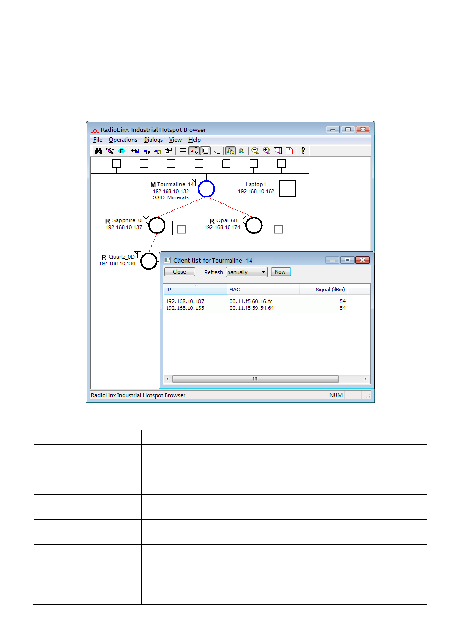
5.9.1 Viewing Wireless Clients in the IH Browser
The Client List dialog box shows information about wireless clients connected to
the currently selected radio.
1 In the IH Broswer, select (click) a radio in either the List View or Topology
View.
2 From the DIALOGS menu choose WIRELESS CLIENTS, or right-click the radio
and choose WIRELESS CLIENTS.
Parameter
Description
Refresh
Specifies the data refresh interval in seconds or minutes. Select
MANUALLY to prevent the IH Browser from automatically updating the
data.
Now
Click NOW to manually update the data.
IP
Displays the IP addresses of the wireless clients connected to the
selected radio.
MAC
Displays the MAC addresses of the wireless clients connected to the
selected radio.
Signal (dBm)
Displays the strength of the signal from the wireless clients connected
to the selected radio.
Age (sec)
Displays the age of the connection to the wireless clients connected to
the selected radio (the amount of time since a packet has been
received from that device).
RLX2-IHx series ♦ 802.11a, b, g, n Using the IH Browser to Manage your Radios
Industrial Hotspots User Manual
ProSoft Technology, Inc. Page 137 of 227
October 30, 2017
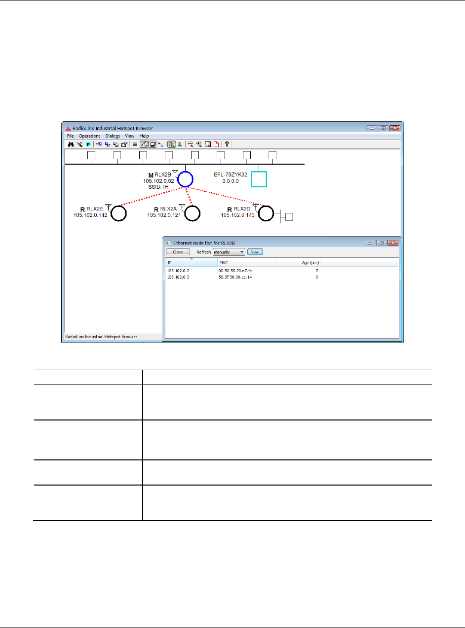
5.9.2 Viewing Ethernet Nodes in the IH Browser
The Ethernet Node List dialog box shows information about devices detected by
the Ethernet interface to the currently selected radio.
1 In the IH Broswer, select (click) a radio in either the List View or Topology
View.
2 From the DIALOGS menu choose ETHERNET NODES, or right-click the radio
and choose ETHERNET NODES.
Parameter
Description
Refresh
Specifies the data refresh interval in seconds or minutes. Select
MANUALLY to prevent the IH Browser from automatically updating the
data.
Now
Click NOW to manually update the data.
IP
Displays the IP addresses of the wireless clients connected to the
selected radio.
MAC
Displays the MAC addresses of the wireless clients connected to the
selected radio.
Age (sec)
Displays the age of the connection to the wireless clients connected to
the selected radio (the amount of time since a packet has been
received from that device).
Using the IH Browser to Manage your Radios RLX2-IHx series ♦ 802.11a, b, g, n
User Manual Industrial Hotspots
Page 138 of 227 ProSoft Technology, Inc.
October 30, 2017
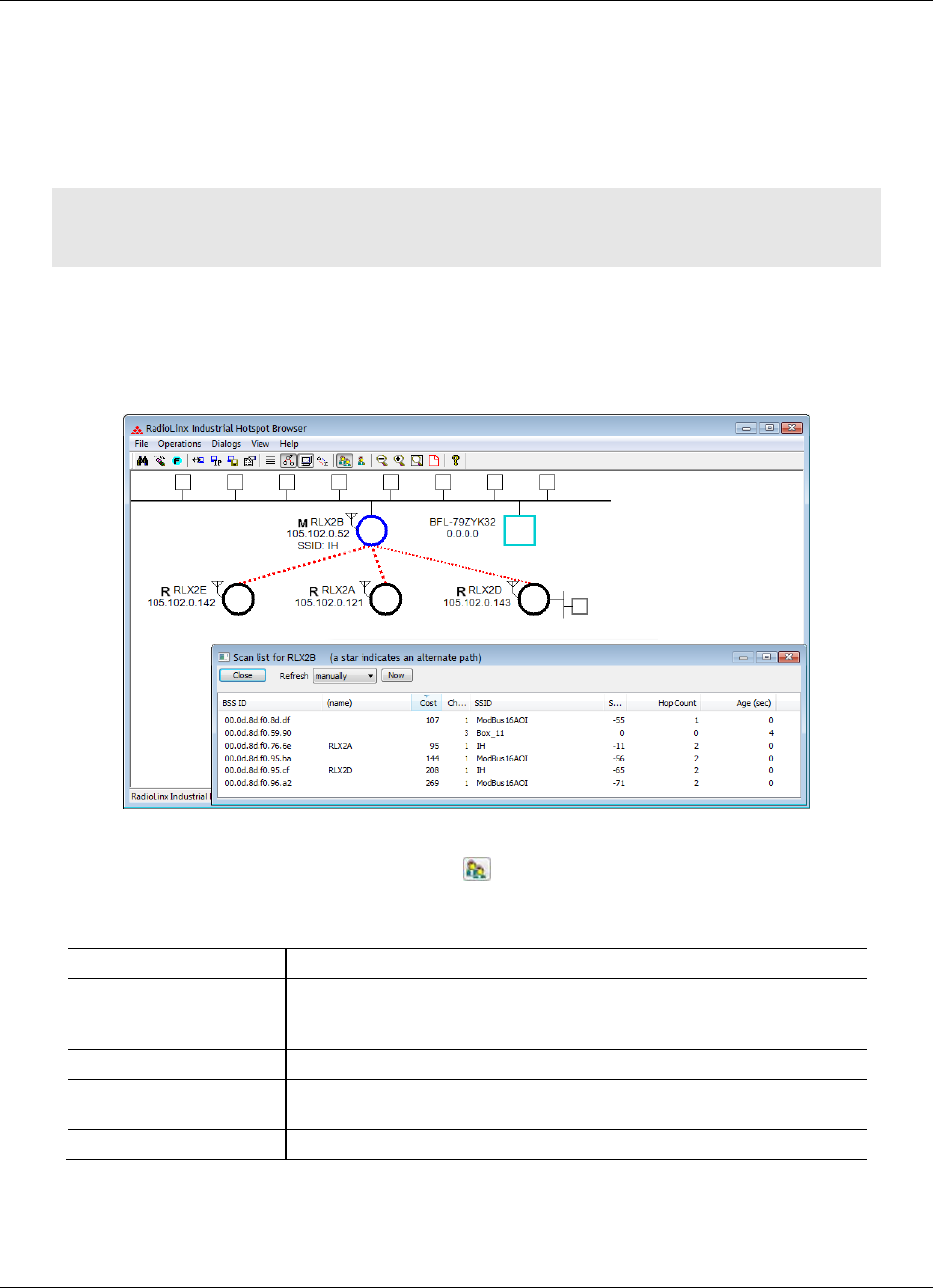
5.9.3 Viewing the Scan List in the IH Browser
The Scan List dialog box shows all 802.11 Access Points known to the selected
radio on this channel (through beacons), even if the Access Point is not linked to
the radio (has a different SSID or uses different encryption). See Detecting
802.11 Access Points (page 32).
Note: This list shows some of the same information available in the Available Parents table in the
Radio Configuration / Diagnostic Utility. See Viewing Available Parents for a Radio (page 65).
1 In the IH Broswer, select (click) a radio in either the List View or Topology
View.
2 From the DIALOGS menu choose SCAN LIST, or right-click the radio and
choose SCAN LIST.
List entries marked with an asterisk * indicate that the entry is an alternate path,
which you can also see if you select the Parents button from the toolbar in the
Topology view (blue lines link the radio to its alternate parents).
Parameter
Description
Refresh
Specifies the data refresh interval in seconds or minutes. Select
MANUALLY to prevent the IH Browser from automatically updating the
data.
Now
Click NOW to manually update the data.
BSS ID
Displays the Basic Service Set Identifier. This is the MAC addresses of
the wireless clients known to the selected radio.
(name)
The name for RLX2-IHx series radios.

RLX2-IHx series ♦ 802.11a, b, g, n Using the IH Browser to Manage your Radios
Industrial Hotspots User Manual
ProSoft Technology, Inc. Page 139 of 227
October 30, 2017
Parameter
Description
Cost
Displays the calculated parent selection cost. The radio evaluates the
link it has to its parent once per second to determine if this link is the
best parent to use. The radio calculates the cost for each entry. The
cost calculation is based not only on the strongest signal, but on several
other factors to provide optimum network communication.
Channel
The radio channel on which the device is transmitting. The channel list
indicates the channel number as well as the frequency (2.4 GHz or 5
GHz bands).
Important: The RLX2-IHx series radio is supplied with a dual-band
antenna that supports both frequency ranges. If you use a different
antenna with the RLX2-IHx series radio, you must choose a channel
and frequency range supported by the antenna. See Appendix G -
Antenna Configuration (page 185).
SSID
Displays the network name (Service Set Identifier) of the Ethernet
device to which the radio is connected. The radio name appears for
RLX2-IHx series radios.
Signal (dBm)
Displays the strength of the signal from the wireless clients connected
to the selected radio.
Hop Count
Displays the number of hops to the Master device. A value of 0 (zero)
appears for non-ProSoft Technology devices.
Age (sec)
Displays the age of the connection to the wireless clients connected to
the selected radio (the amount of time since a packet has been
received from that device).
Using the IH Browser to Manage your Radios RLX2-IHx series ♦ 802.11a, b, g, n
User Manual Industrial Hotspots
Page 140 of 227 ProSoft Technology, Inc.
October 30, 2017
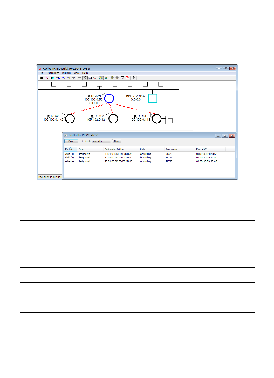
5.9.4 Viewing the Port Table in the IH Browser
The Port List dialog box shows all active ports on the selected radio.
1 In the IH Broswer, select (click) a radio in either the List View or Topology
View.
2 From the DIALOGS menu choose PORT TABLE, or right-click the radio and
choose PORT TABLE.
The port table is a list of all the active ports on the radio.Each RLX2-IHx series
radio has up to 34 active ports: one Ethernet wired port, one parent radio
frequency link, and up to 32 child radio frequency links.
Parameter
Description
Refresh
Specifies the data refresh interval in seconds or minutes. Select
MANUALLY to prevent the IH Browser from automatically updating the
data.
Now
Click NOW to manually update the data.
Port #
Displays the selected radio's port number.
Type
Displays the type of the port (ETHERNET PORT, PARENT RF LINK, CHILD
RF LINK).
Designated Bridge
The next bridge toward the Spanning Tree root for this port.
State
Displays the current Spanning Tree state of the port (BLOCKING,
LEARNING, LISTENING, and FORWARDING). Forwarding packets can be
transferred.
Peer Name
Displays the name of the Master radio if the current radio is a Repeater
radio.
Peer MAC
Displays the MAC address of the Master radio if the current radio is a
Repeater radio.
RLX2-IHx series ♦ 802.11a, b, g, n Using the IH Browser to Manage your Radios
Industrial Hotspots User Manual
ProSoft Technology, Inc. Page 141 of 227
October 30, 2017
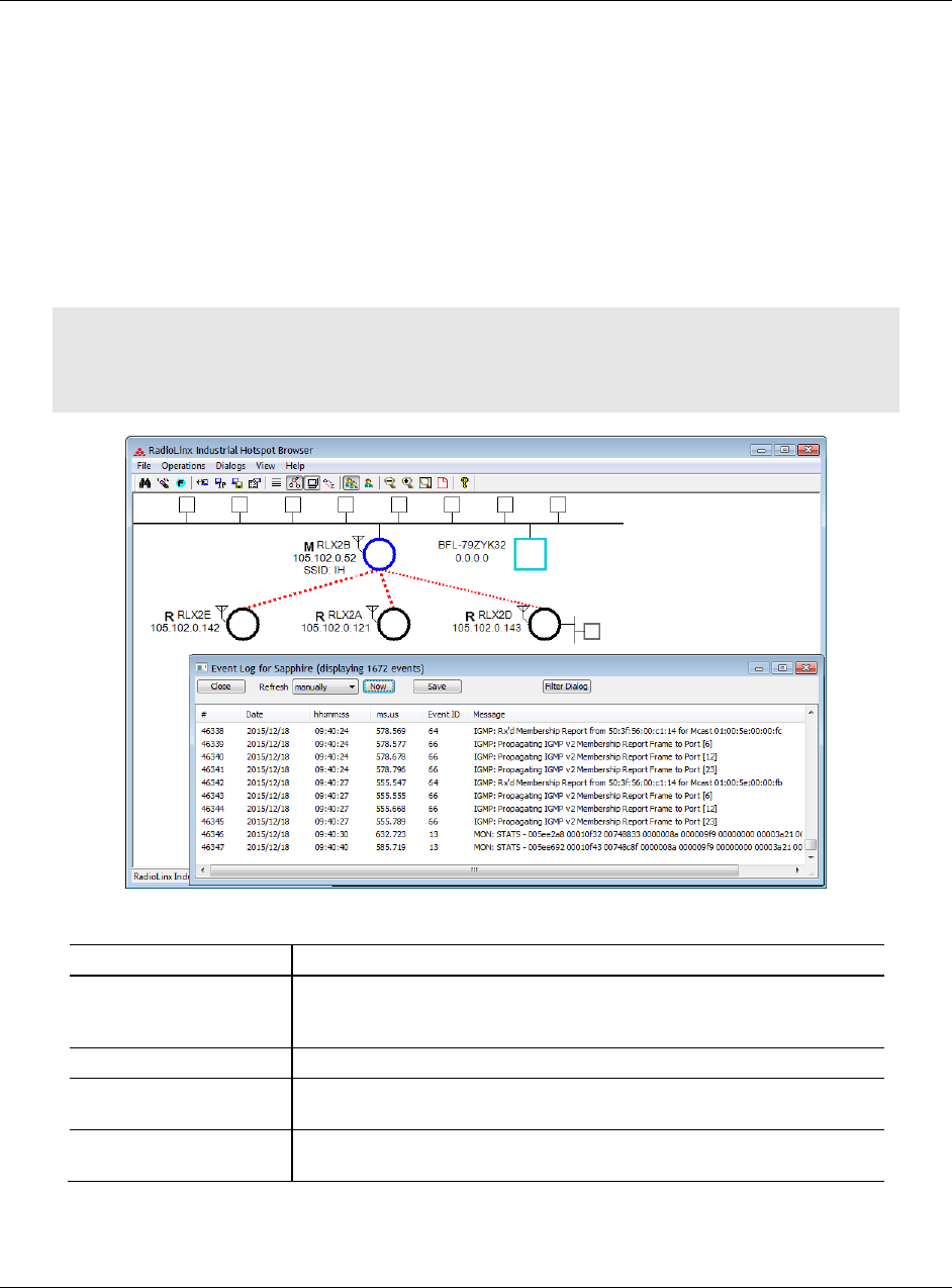
5.9.5 Viewing the Radio Event Log in the IH Browser
The Event Log dialog box displays the history of events that have been recorded
by the currently selected radio. This can be useful for troubleshooting problems.
1 In the IH Broswer, select (click) a radio in either the List View or Topology
View.
2 From the DIALOGS menu choose EVENT LOG, or right-click the radio and
choose EVENT LOG.
The Event Log shows the history of a particular radio. You can save the Event
Log to a text file for troubleshooting purposes.
Note: The filter conditions that you set in the Event Log Filter dialog box affect both the display of
events in the Event Log dialog box, and the events in the file you create when you click SAVE. See
Setting the Event Log Filter (page 142).
Parameter
Description
Refresh
Specifies the data refresh interval in seconds or minutes. Select
MANUALLY to prevent the IH Browser from automatically updating the
data.
Now
Click NOW to manually update the data.
Save
Click SAVE to save the Event Log to a file for troubleshooting or sending
to ProSoft Technology Technical Support.
Filter Dialog
Click FILTER DIALOG to change the Event Log filtering to show or hide
certain events. See Setting the Event Log Filter (page 142).
Using the IH Browser to Manage your Radios RLX2-IHx series ♦ 802.11a, b, g, n
User Manual Industrial Hotspots
Page 142 of 227 ProSoft Technology, Inc.
October 30, 2017
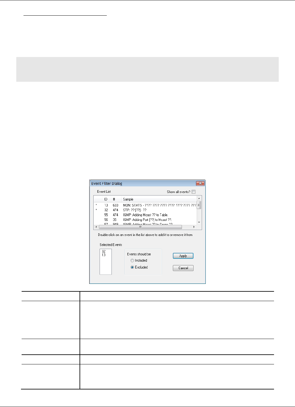
Setting the Event Log Filter
The Event Filter dialog box allows you to include or exclude specific event types
from the Event Log. The filter conditions that you set in this dialog box affect both
the display of events in the Event Log dialog box, and the events in the file you
create when you click SAVE in the Event Log dialog box.
Note: The filter conditions are reset to the default state (include all events) when you close the
Event Log dialog box.
1 In the IH Broswer, click on a radio in either the List View or Topology View.
2 From the DIALOGS menu choose EVENT LOG, or right-click the radio and
choose EVENT LOG.
3 In the Event Log dialog box, click FILTER.
4 Double-click on an event in the EVENT LIST to add it to the SELECTED EVENTS
list. An asterisk (*) appears next to the event types in the Selected Events list.
You can double-click on the event in the EVENT LIST a second time to remove
it from the SELECTED EVENTS list.
5 Use the EVENTS SHOULD BE parameters to include only the selected events,
or exclude the selected events.
Parameter
Description
Event List
Displays a list of different types of events in the log, sorted by EVENT ID. By
default, this list only includes events types that are in the radio's Event Log.
Double-click an event type to add it to the Selected Events list.
Double-click the event type again to remove it from the Selected Events
list.
Show all events
Select this check box to show all event types, even if the type is not in the
radio's Event Log.
Selected Events
Displays the list of selected event types.
Events should be
Specifies whether to include only the selected events, or exclude them.
INCLUDED - Show only the selected events in the Event Log.
EXCLUDED - Show all events in the Event Log except the selected events.
RLX2-IHx series ♦ 802.11a, b, g, n Using the IH Browser to Manage your Radios
Industrial Hotspots User Manual
ProSoft Technology, Inc. Page 143 of 227
October 30, 2017
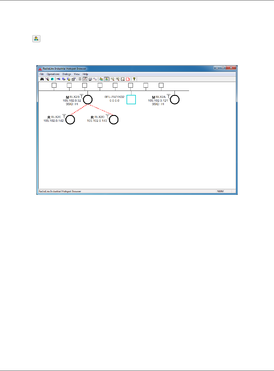
5.9.6 Viewing Parent Radios in the IH Browser
You can show the current Parent radio or all possible alternate Parent radios for
the Repeater radios in the Topology View.
The Show Selected Parents button (or from the VIEW menu choose SHOW
PARENTS - ONE) shows the link from Repeater radios to their current Parent
radio in red.
Using the IH Browser to Manage your Radios RLX2-IHx series ♦ 802.11a, b, g, n
User Manual Industrial Hotspots
Page 144 of 227 ProSoft Technology, Inc.
October 30, 2017
The Show All Parents button (or from the VIEW menu choose SHOW
PARENTS - ALL) shows links to alternate Parent radios in blue (If the Repeater
radios can detect other radios in the network). This gives a graphical
representation of the number of alternate paths available to a radio should its
parent link go down.
Note: You can also display a detailed list of each of the alternate Parent radios right-clicking a
radio and choosing SCAN LIST. This list shows the RLX2-IHx series radios in the same network and
all 802.11 Access Points on other networks. See Viewing the Scan List in the IH Browser (page
138).
RLX2-IHx series ♦ 802.11a, b, g, n Diagnostics and Troubleshooting
Industrial Hotspots User Manual
ProSoft Technology, Inc. Page 145 of 227
October 30, 2017
6 Diagnostics and Troubleshooting
In This Chapter
Checking the Ethernet Cable ............................................................... 146
LED Display ......................................................................................... 146
Resetting a RLX2-IHx series Radio ..................................................... 148
Unable to scan for AP's error message ............................................... 149
Finding Missing Radios ....................................................................... 150
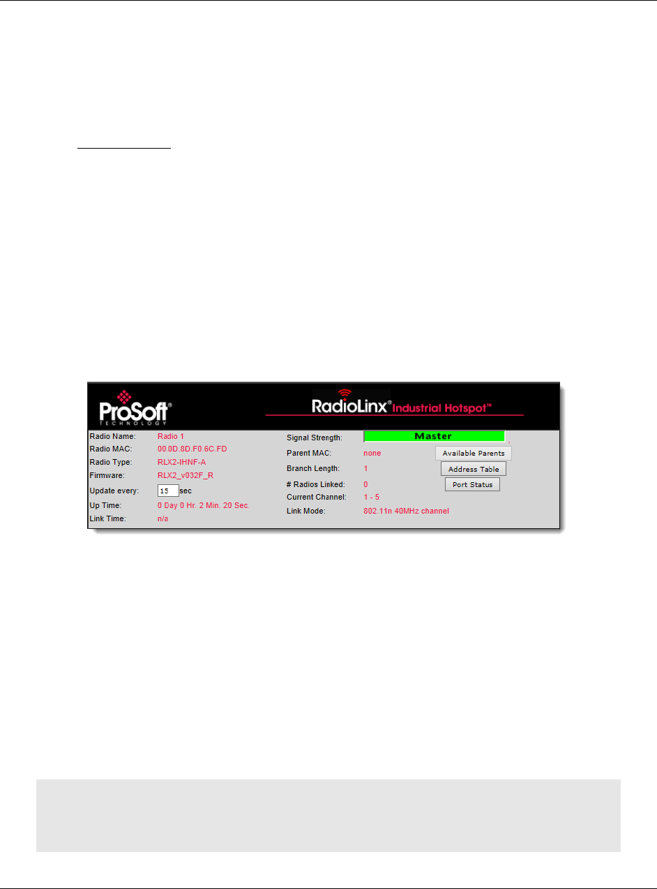
Use the IH Browser’s diagnostic and signal strength settings at the top of the
Radio Settings window to make sure the network is working properly:
Signal Strength: This shows the radio’s signal strength.
o Master appears if this is a Master radio.
o Scanning appears if the radio is scanning to find another radio to connect
to.
o Not Connected appear If the radio is not connected to a network and not
currently scanning.
Update every: Specifies the interval (in seconds) between updates to the
display. The default is 15 seconds.
The other parameters on this display are Read-only, and describe the radio
and its current state.
Tip: You can display the help topic for any parameter in the dialog box by clicking the parameter
name. The parameter name turns blue when you move the cursor over a parameter with a help
topic.
Diagnostics and Troubleshooting RLX2-IHx series ♦ 802.11a, b, g, n
User Manual Industrial Hotspots
Page 146 of 227 ProSoft Technology, Inc.
October 30, 2017
You can perform the following troubleshooting routines:
Check the Ethernet cable
Check the LEDs on the radio
Retrieve the default password by resetting the radio
View error messages in the IH Browser
Find missing radios
6.1 Checking the Ethernet Cable
If the radio’s Ethernet port is connected to a PC or network, and the Ethernet
LED does not light on the radio, there may be a problem with the Ethernet cable.
Verify that the cable is plugged into the radio at one end, and to an Ethernet hub,
a PC, or a 10/100/1000 Base-T Ethernet switch at the other end.
If using the PoE injector, verify that the M12 to RJ45 cable is connected between
the radio and the injector and also that the Ethernet patch cable is connected
between the injector and the switch.
Note: The RLX2-IHx series radio auto-detects the Ethernet connection type, and does not require
a crossover cable for direct connection to a PC.
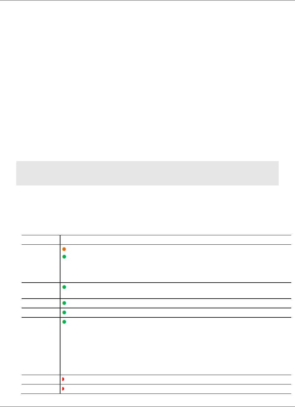
6.2 LED Display
The RLX2-IHx series radio front panel includes a set of LEDs that indicate the
radio’s status.
LED
Description
POWER
Booting up
Fully operational
This two-color LED turns amber when power is first applied. After power is applied, this
LED goes out completely for about four seconds while the internal hardware is initialized.
After initialization the power LED turns green, indicating the radio is fully operational.
RF
TRANSMIT
Transmitting data over the wireless interface
RF RECEIVE
Receiving data over the wireless interface
SERIAL
Receiving serial data
ETHERNET
Transmitting Ethernet data over the wireless interface
Note that the state of the front-panel ETHERNET LED may not necessarily correspond to
the state of the DATA LED on the Ethernet connector. The DATA LED on the Ethernet
connector indicates traffic over the wired link, while the ETHERNET LED indicates network
data sent or received through the wireless link.
For example, if the radio is pinged over the wired link, the DATA LED on the Ethernet
connector blinks but the ETHERNET LED does not (because the ping packet was not
transmitted over the air).
NET
Blinks if SD card with new configuration inserted. Reserved for future additional use.
MOD
Blinks if SD card with new configuration inserted. Reserved for future additional use.
RLX2-IHx series ♦ 802.11a, b, g, n Diagnostics and Troubleshooting
Industrial Hotspots User Manual
ProSoft Technology, Inc. Page 147 of 227
October 30, 2017
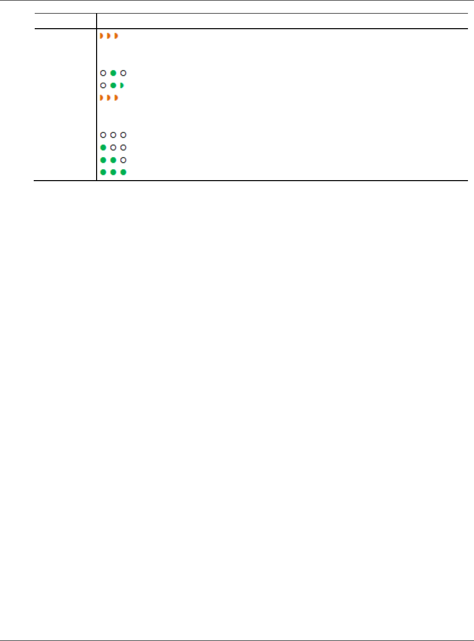
LED
Description
SIGNAL
STRENGTH
Blinks if SD card inserted with new configuration. This is for all radio modes.
Radios in Master mode:
No radios linked
One or more radios linked (right LED blinking).
DFS Channel Availability Check in progress (all LEDs blinking Amber)
Radios in Repeater or Client mode:
No Signal
Radio linked, Poor Signal
Radio linked, Fair Signal
Radio linked, Good Signal
The following LEDs should light when you connect the power and Ethernet
cables to the radio.
The POWER LED should turn green.
The SPEED LED on the Ethernet connector should indicate a valid wired link.
This LED is located at the top of the Ethernet RJ-45 connector and is marked
SPEED
o OFF = 10 MB
o ON = 100 MB
o BLINK = 1GB.
The RF TRANSMIT and RF RECEIVE LEDs should start to blink
occasionally.
For radios in Repeater or Client mode, all three SIGNAL STRENGTH LEDs blink
just after the radio links to the Master radio but before fully authenticating the link.
Normally this lasts only a few seconds. If the SIGNAL STRENGTH LEDs blink for
longer than a few seconds, or do not stop blinking, it usually means the
encryption keys are not correct. The Wireless Security Settings on a Repeater
radio must match those on the Master radio. See Configuring a Radio - Getting
Started (page 44).
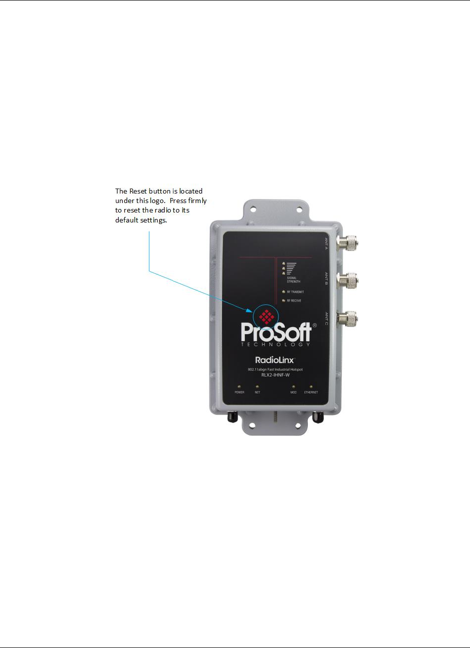
Diagnostics and Troubleshooting RLX2-IHx series ♦ 802.11a, b, g, n
User Manual Industrial Hotspots
Page 148 of 227 ProSoft Technology, Inc.
October 30, 2017
6.3 Resetting a RLX2-IHx series Radio
If you lose the password to a radio, you cannot change the radio settings. You
can reset the radio to restore the default password, but the radio loses all the
configuration settings and returns to the default settings.
6.3.1 Resetting the RLX2-IHNF-W and RLX2-IHNF-WC
These steps resets the radio to its default settings, including the default
password.
1 Remove power from the radio.
2 Press the Reset button. The Reset button is located on the front of the unit
just under the ProSoft logo.
3 While holding down the button, apply power to the radio and continue to hold
the button down for 30 seconds.
This resets the radio to its default settings. You can now log in to the Radio
Configuration / Diagnostic Utility for the radio using the default password:
password.
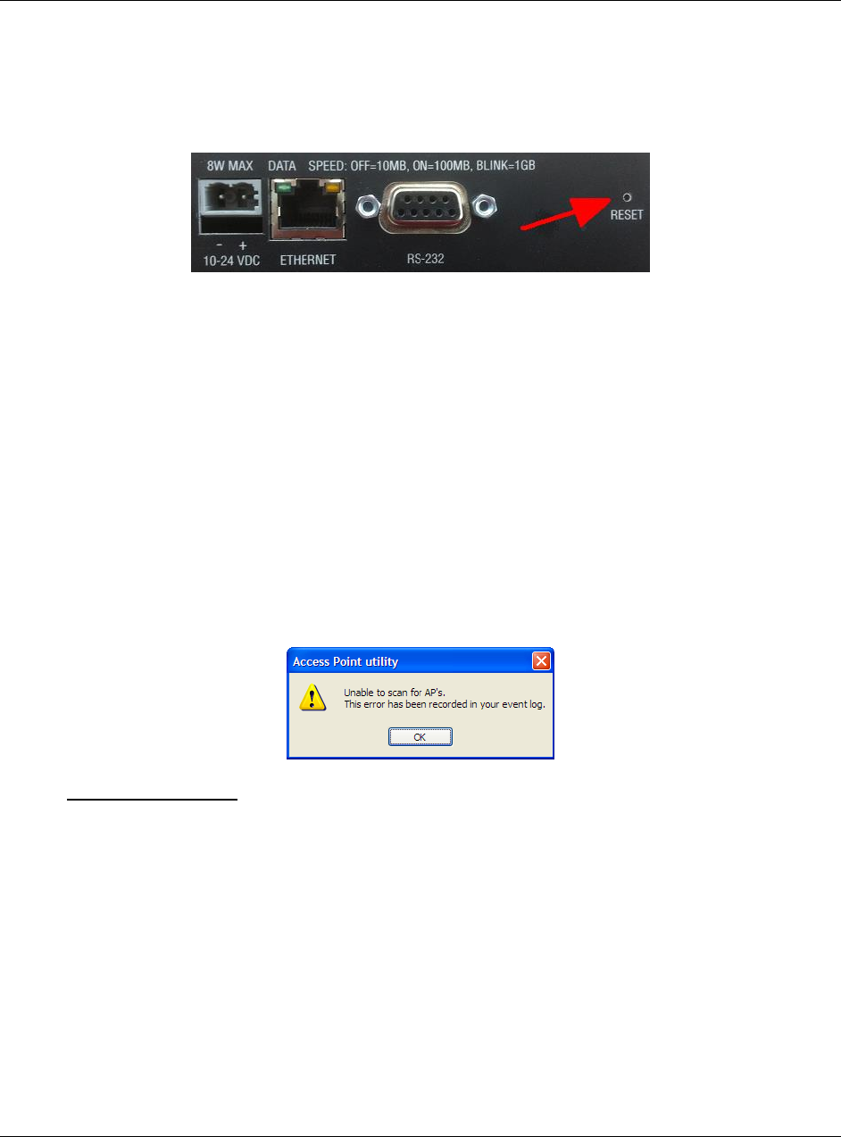
RLX2-IHx series ♦ 802.11a, b, g, n Diagnostics and Troubleshooting
Industrial Hotspots User Manual
ProSoft Technology, Inc. Page 149 of 227
October 30, 2017
6.3.2 Resetting All Other Radios
These steps reset the radio to its default settings, including the default password.
1 Remove power from the radio.
2 Locate the Reset button hole.
3 Insert the end of a paperclip or similar device into the hole to press the reset
button.
4 While pressing the reset button in with a paperclip, apply power to the radio,
and continue to hold down the reset button for 30 seconds.
This resets the radio to its default settings. You can now log in to the Radio
Configuration / Diagnostic Utility for the radio using the default password:
password.
6.4 Unable to scan for AP's error message
The Unable to scan for AP's error message may appear in the IH Browser when
it attempts to scan for radios and no valid network connection exists on the PC
(wired or wireless).
To correct this error
1 Confirm that the PC has at least one active network (LAN) connection. It
could be a wired Ethernet connection or a wireless 802.11 connection.
2 Confirm that the network connection has a valid IP address. The network
connection might need to have a static IP address assigned to it. Check the
IP address of the network connection to determine that one has been
assigned.

Diagnostics and Troubleshooting RLX2-IHx series ♦ 802.11a, b, g, n
User Manual Industrial Hotspots
Page 150 of 227 ProSoft Technology, Inc.
October 30, 2017
6.5 Finding Missing Radios
If the radios are not visible in the IH Browser, try the following:
1 Refresh the IH Browser display. See Refreshing the Display in the IH
Browser (page 42). The IH Browser sends scans as broadcast messages,
which can be dropped in RF connections, requiring that you repeat the scan.
2 Disable any software firewall running on the PC (This is most common in
Windows XP and newer). Open the Network connections folder in the
Windows Control Panel, then open the Local Area Connection Properties
window and verify that the check box under INTERNET CONNECTION FIREWALL
is not checked.
3 If these steps do not help, verify that the PC running the IH Browser and the
radios are connected to the same local network.
4 In the IH Browser, change to the Topology view. From the VIEW menu, click
TOPOLOGY VIEW. Any unlinked radios may appear at the bottom of the
window. Scroll down to see all the unlinked radios. If you still cannot see the
radios in the IH Browser, call ProSoft Technology Technical Support. See
Contacting Technical Support (page 211).

RLX2-IHx series ♦ 802.11a, b, g, n Appendix A - Adding a Radio to RSLogix 5000
Industrial Hotspots User Manual
ProSoft Technology, Inc. Page 151 of 227
October 30, 2017
7 Appendix A - Adding a Radio to RSLogix 5000
In This Chapter
Adding the Radio to RSLogix 5000 ..................................................... 152
Importing the Add-On Instruction ......................................................... 155
RLX2 Controller Tags .......................................................................... 159
You can use an Add-On Instruction (AOI) to add an RLX2-IHx series radio to
RSLogix 5000™. You can then extract information from the radio and transfer it
to the ControlLogix processor connected by EtherNet/IP™. This allows you to
view and use the radio status and diagnostic information in the program on the
controller.
Note: You must download the RLX2-IHx series radio Add-On Instruction from the ProSoft
Technology website. Go to www.prosoft-technology.com and search for your radio. From the
RLX2-IHx series radio webpage, download the Add-On Instruction.
There are two procedures that you must complete in order to import and use the
RLX2-IHx series Add-On Instruction in RSLogix 5000.
1 Add the RLX2-IHx series radio to a project in RSLogix 5000.
2 Import the AOI into the MainRoutine ladder logic in the same project.
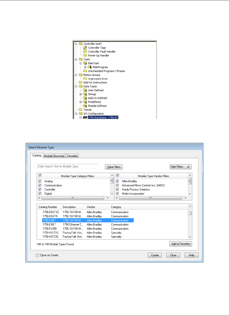
Appendix A - Adding a Radio to RSLogix 5000 RLX2-IHx series ♦ 802.11a, b, g, n
User Manual Industrial Hotspots
Page 152 of 227 ProSoft Technology, Inc.
October 30, 2017
7.1 Adding the Radio to RSLogix 5000
1 In RSLogix 5000, open an existing project, or create a new project
2 In the Controller Organizer, right-click 1756 BACKPLANE, 1756-A7 and then
click NEW MODULE.
3 In the Select Module Type dialog box, select the correct Ethernet card (ENBT
in this example) and click OK.
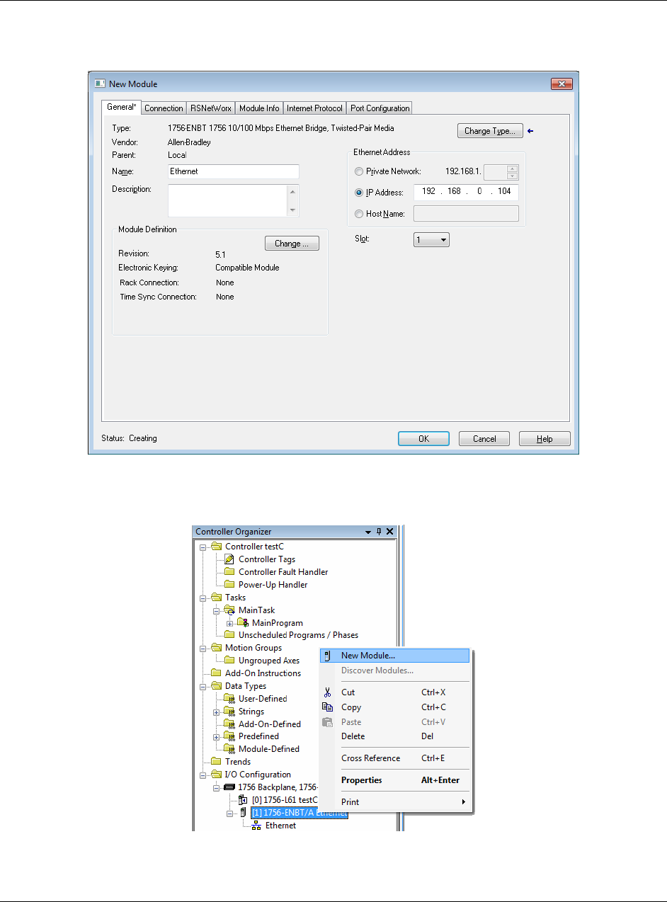
RLX2-IHx series ♦ 802.11a, b, g, n Appendix A - Adding a Radio to RSLogix 5000
Industrial Hotspots User Manual
ProSoft Technology, Inc. Page 153 of 227
October 30, 2017
4 Enter a name for the card (Ethernet in this example) and the IP ADDRESS and
then click OK.
5 In the Controller Organizer, right-click the new ETHERNET module and then
click NEW MODULE.
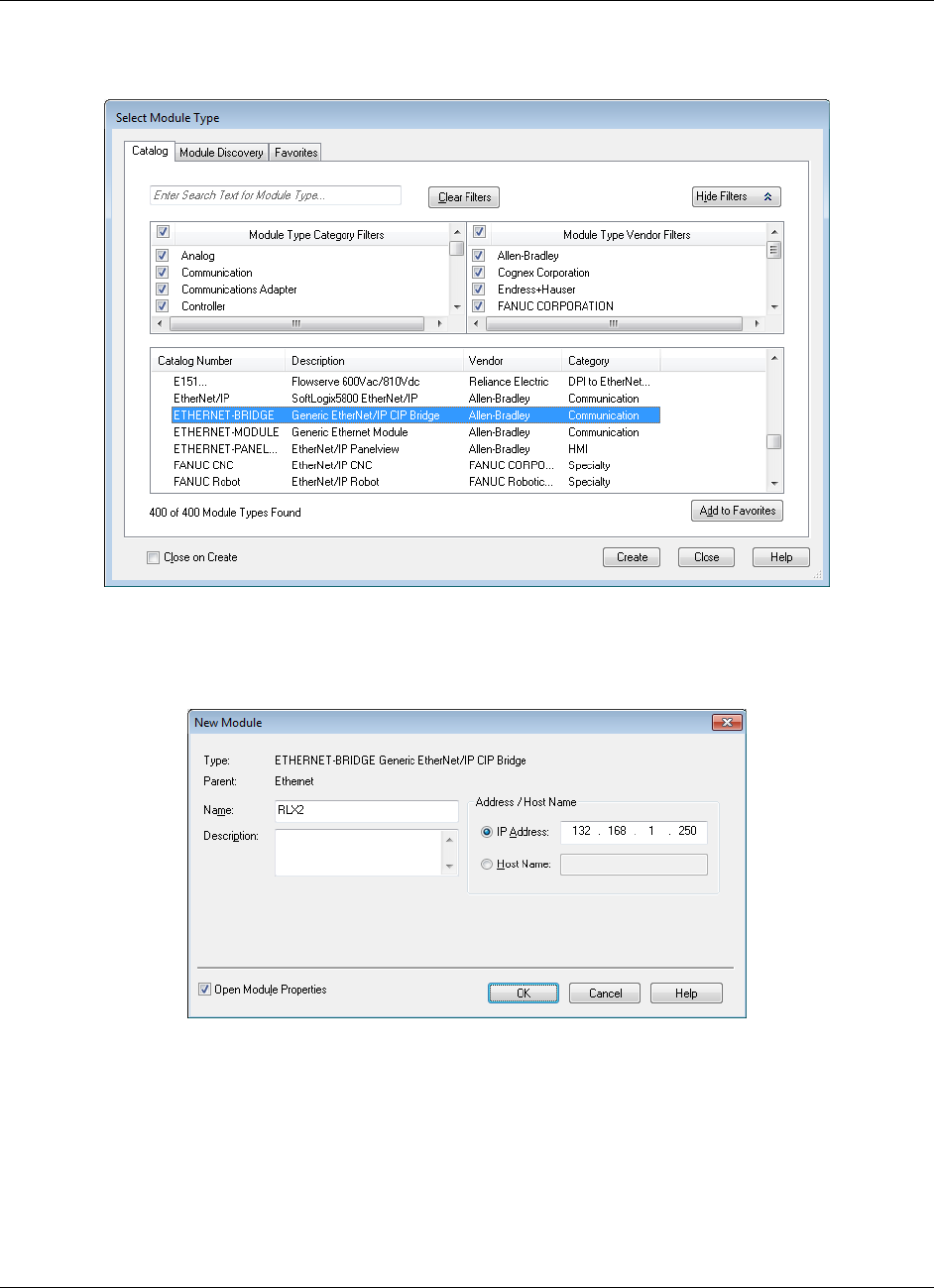
Appendix A - Adding a Radio to RSLogix 5000 RLX2-IHx series ♦ 802.11a, b, g, n
User Manual Industrial Hotspots
Page 154 of 227 ProSoft Technology, Inc.
October 30, 2017
6 In the Select Module Type dialog box, click ETHERNET-BRIDGE GENERIC
ETHERNET/IP CIP BRIDGE and then click OK.
7 In the New Module dialog, enter the NAME (RLX2 in this example).
8 Select the IP ADDRESS radio button and type in the IP address of the RLX2-
IHx series radio, and then click OK.
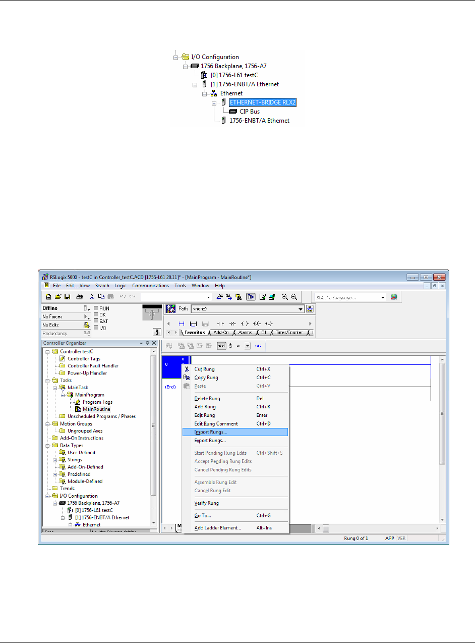
RLX2-IHx series ♦ 802.11a, b, g, n Appendix A - Adding a Radio to RSLogix 5000
Industrial Hotspots User Manual
ProSoft Technology, Inc. Page 155 of 227
October 30, 2017
9 In the Module Properties dialog box, click OK. The Ethernet Bridge appears
in the Controller Organizer.
7.2 Importing the Add-On Instruction
1 In RSLogix 5000, in the Controller Organizer window, expand the TASKS
folder until you see the MAINPROGRAM folder.
2 Under the MAINPROGRAM folder, double-click MAINROUTINE to open the
MainRoutine in the Ladder Editor.
3 Right-click an empty rung in the routine, and then click IMPORT RUNG...
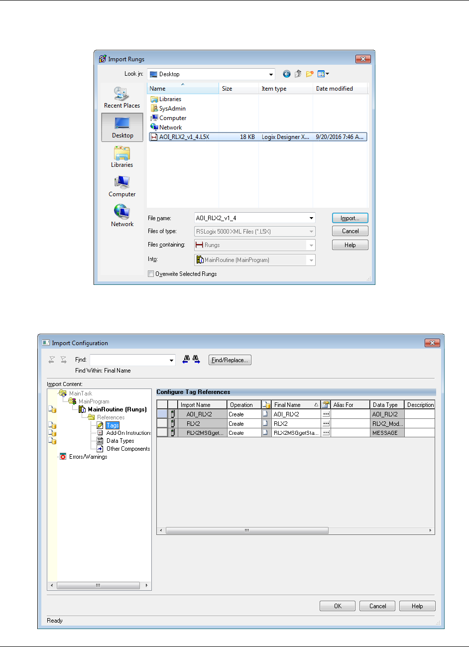
Appendix A - Adding a Radio to RSLogix 5000 RLX2-IHx series ♦ 802.11a, b, g, n
User Manual Industrial Hotspots
Page 156 of 227 ProSoft Technology, Inc.
October 30, 2017
4 Navigate to the location on your PC where you saved the Add-On Instruction
(for example, Desktop). Select the .L5X file and click IMPORT.
5 This opens the Import Configuration dialog box. Click TAGS to see the
controller tags that the Add-On Instruction creates.
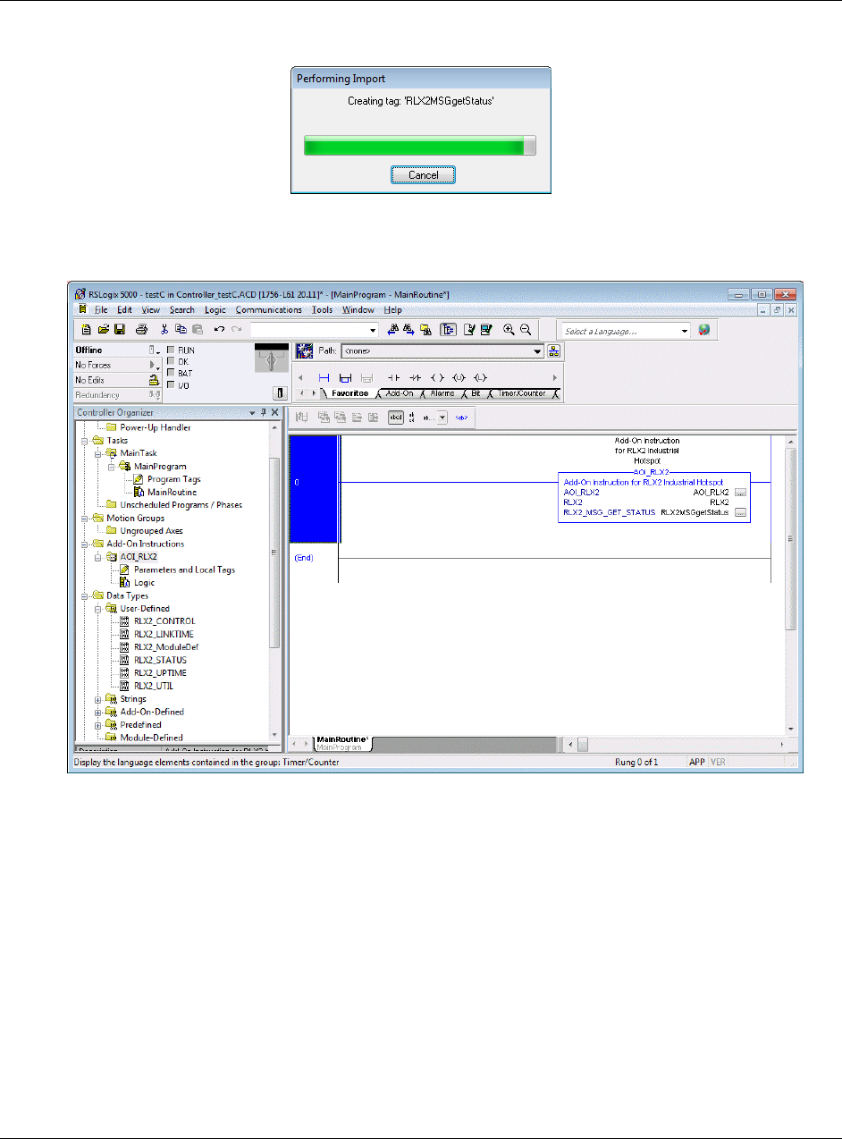
RLX2-IHx series ♦ 802.11a, b, g, n Appendix A - Adding a Radio to RSLogix 5000
Industrial Hotspots User Manual
ProSoft Technology, Inc. Page 157 of 227
October 30, 2017
6 Click OK to import the AOI. A progress bar appears during the import.
7 After the import completes, the new rung with the Add-On Instruction appears
in the Ladder editor.
The procedure also imports new User Defined Data Types, Controller Tags,
and the Add-On instruction for your project.
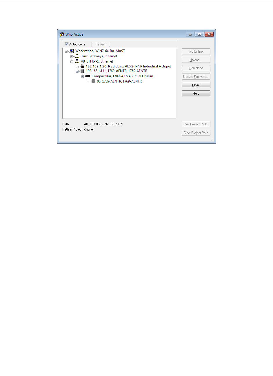
Appendix A - Adding a Radio to RSLogix 5000 RLX2-IHx series ♦ 802.11a, b, g, n
User Manual Industrial Hotspots
Page 158 of 227 ProSoft Technology, Inc.
October 30, 2017
8 Ensure that a communications path exists using the Who Active dialog as
shown.
9 Save the project. When ready, download the project to the processor.
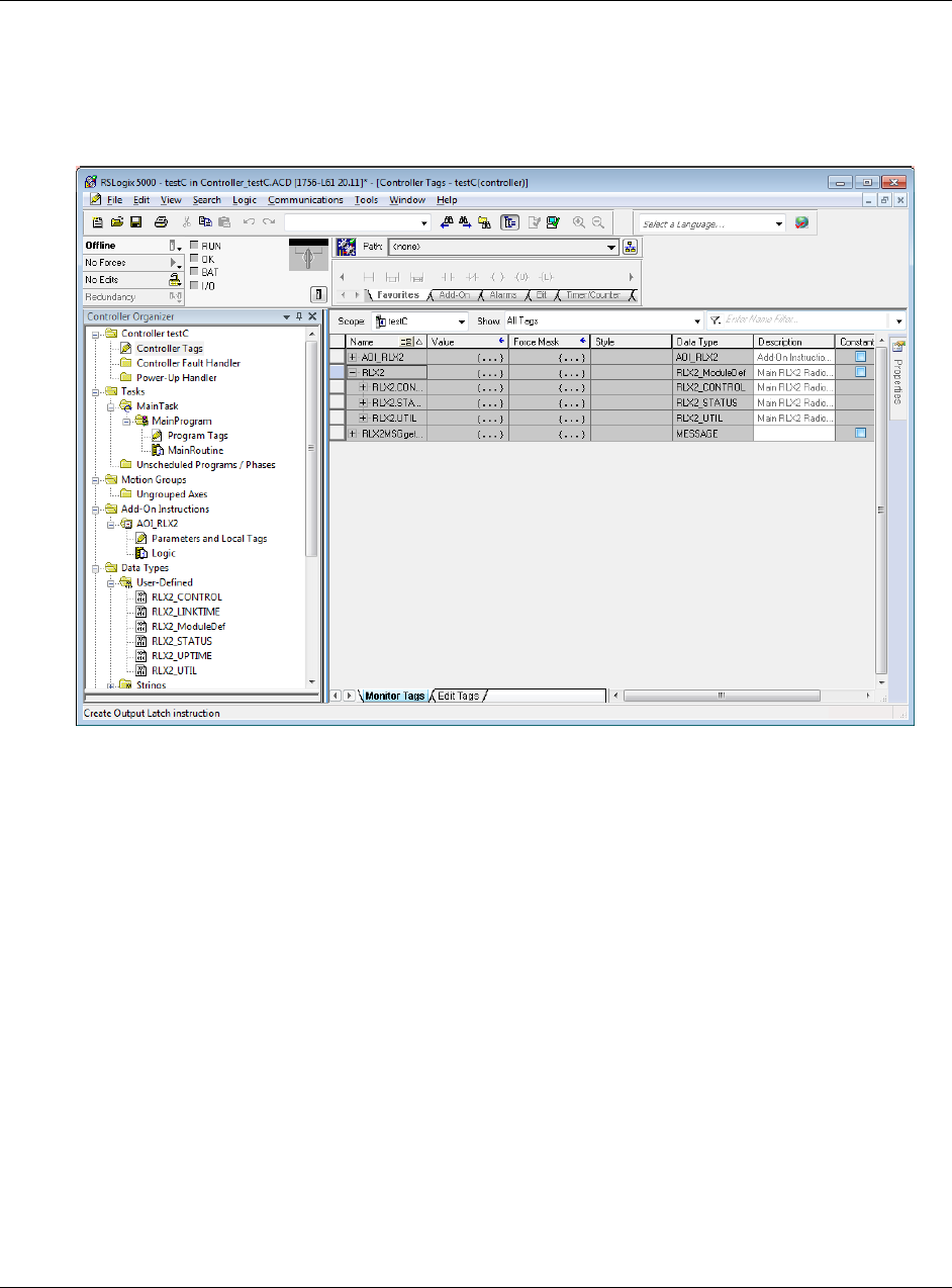
RLX2-IHx series ♦ 802.11a, b, g, n Appendix A - Adding a Radio to RSLogix 5000
Industrial Hotspots User Manual
ProSoft Technology, Inc. Page 159 of 227
October 30, 2017
7.3 RLX2 Controller Tags
You use the controller tags in RSLogix 5000 to monitor and control elements of
the RLX2-IHx series radio from RSLogix 5000. You use only the RLX2.xxx
controller tag structure for this purpose.
7.3.1 RLX2.CONTROL
This array contains trigger bits used to request functions from the RLX2-IHx
series radio. The description is "Main RLX2 Radio definition Reads status of
Diagnostic data from RLX2."
After execution, the bit is reset to 0 to be ready for the next execution.

Appendix A - Adding a Radio to RSLogix 5000 RLX2-IHx series ♦ 802.11a, b, g, n
User Manual Industrial Hotspots
Page 160 of 227 ProSoft Technology, Inc.
October 30, 2017
7.3.2 RLX2.STATUS
This array is populated when the RLX2.CONTROL.Get_Status_Data is triggered.
The following is the CIP™ object definition to read the RLX2-IHx Diagnostics and
Status information.
CIP Data Tag Name
Data Type
Description
RLX2.STATUS.SSID
SINT[32]
Service Set Identifier is a name assigned to the
wireless network
RLX2.STATUS.IPAddress
SINT[4]
IP address of RLX2-IHx radio
RLX2.STATUS.MACAddress
SINT[6]
Physical Media Access Control (MAC) address of
the device
RLX2.STATUS.NetworkMode
SINT
RLX2 radio network mode (Master= 6 Repeater=7
Client=1)
RLX2.STATUS.ConnectionState
SINT
Connection State of RLX2 radio found at the bit-
level (RLX2.STATUS.ConnectionState.x)
Bit sequence [yyyy 0001] = 1 = Not connected
Bit sequence [yyyy 0010] = 2 = Scanning
Not reported = 3 = Locally connected
Bit sequence [yyyy 0100] = 4 = Globally connected
Where y = RLX2 radio model type:
Bit sequence [0001 zzzz] = 802.11g (2.4 GHz) radio
Bit sequence [0010 zzzz] = 802.11a (5 GHz) radio
Bit sequence [0011 zzzz] = 802.11n radio
Example:
Bit sequence 0010 0100 = 36 = Globally connected
5 Ghz radio
RLX2.STATUS.SignalStrength
INT
Current Strength of the signal in dBm
RLX2.STATUS.Channel
SINT
Current Channel in which RLX2-IHx is transmitting
RLX2.STATUS.WEP
SINT
WEP encryption key
RLX2.STATUS.Flags
DINT
Flags:
Flag [0/1 ]= Extension channel
Flag [2] = SSIDhidden
Flag [3] = Allow Children
Flag [4/5] = STP/RSTP
Flag [6] = TXusingGI
RLX2.STATUS.MasterMACAddress
SINT[6]
MAC Address of Parent Radio in which Repeater or
Client is linked
RLX2.STATUS.HopCount
SINT
Number of hops to the master
RLX2.STATUS.PortStatus
SINT
Ethernet Port Status
1 = 10 Mb/s
2 = 100 Mb/s
3 = 1000 Mb/s
RLX2.STATUS.Associations
INT
Number of network elements to which radio has
wireless connection
RLX2.STATUS.BridgeAssociations
INT
Number of devices to which radio has wireless
connection

RLX2-IHx series ♦ 802.11a, b, g, n Appendix A - Adding a Radio to RSLogix 5000
Industrial Hotspots User Manual
ProSoft Technology, Inc. Page 161 of 227
October 30, 2017
RLX2.STATUS.TxRadioThroughput
INT
Transmit throughput in kilobits per second
RLX2.STATUS.RxRadioThroughput
INT
Receive throughput in kilobits per second
RLX2.STATUS.Uptime
INT
This is the amount of time the radio has been
running since power up
(Days/Hours/Minutes/Seconds)
RLX2.STATUS.Linktime
DINT
The time the radio has been linked
(Days/Hours/Minutes/Seconds)
RLX2.STATUS.TxPacketRate
DINT
Total number of packets transmitted
RLX2.STATUS.RxPacketRate
DINT
Total number of packets received
RLX2.STATUS.ModuleName
DINT
The name of the radio
RLX2.STATUS.ProductName
SINT[32]
Name of product
RLX2.STATUS.ImageVerStr
SINT[32]
Firmware version loaded in device
RLX2.STATUS.TxGood
SINT[28]
Number of Good Transmitted Frames
RLX2.STATUS.RxGood
DINT
Number of Good Received Frames
RLX2.STATUS.TxBad
DINT
Number of Bad Transmitted Frames
RLX2.STATUS.RxBad
DINT
Number of Bad Received Frames
RLX2.STATUS.TxDirectedFrames
DINT
Number of Transmitted Directed Frames
RLX2.STATUS.TxMulticastFrames
DINT
Number of Transmitted Multicast Frames
RLX2.STATUS.TxBroadcastFrames
DINT
Number of Transmitted Broadcast Frames
RLX2.STATUS.RxDirectedFrames
DINT
Number of Received Directed Frames
RLX2.STATUS.RxMulticastFrames
DINT
Number of Received Multicast Frames
RLX2.STATUS.RxBroadcastFrames
DINT
Number of Transmitted Broadcast Frames
RLX2.STATUS.RxCRCErr
DINT
Number of CRC Errors

RLX2-IHx series ♦ 802.11a, b, g, n
User Manual Industrial Hotspots
Page 162 of 227 ProSoft Technology, Inc.
October 30, 2017
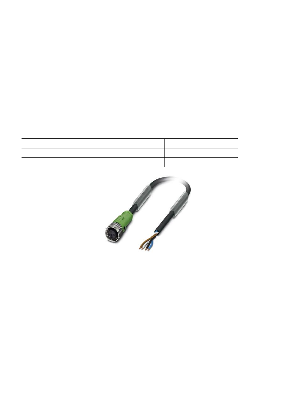
RLX2-IHx series ♦ 802.11a, b, g, n Appendix B - Radio Hardware
Industrial Hotspots User Manual
ProSoft Technology, Inc. Page 163 of 227
October 30, 2017
8 Appendix B - Radio Hardware
In This Chapter
Radio Power Requirements (RLX2-IHNF-W) ...................................... 163
Radio Power Requirements (All other radios) ..................................... 165
Ethernet Cable Specifications ............................................................. 167
Ethernet Cable Configuration .............................................................. 168
8.1 Radio Power Requirements (RLX2-IHNF-W)
These cables are available for purchase from ProSoft Technology:
Description
ProSoft Part Number
Power Cable, 3m (7 ft), M12 to un-terminated leads
CULPWR-M12-010
Power Cable, 10m (33 ft), M12 to un-terminated leads
CULPWR-M12-033
The RLX2-IHNF-W and WC radios accept PoE configuration.
The RLX2-IHNF-W radio is equipped with a power M12 port (IEC 61076-2-
101).
The RLX2-IHNF-WC Ethernet and PoE cable protrudes from the module.
There is no M12 port.
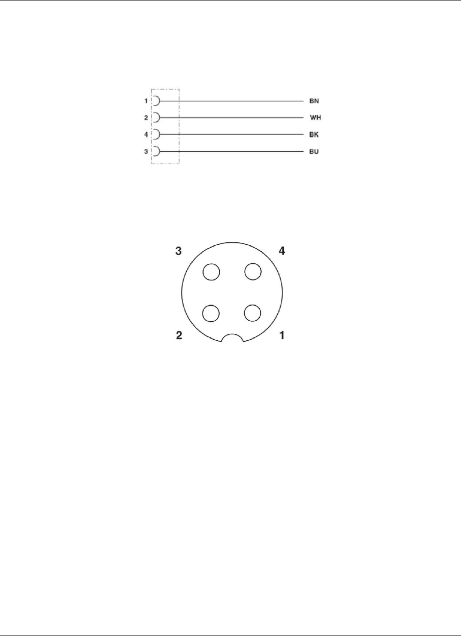
Appendix B - Radio Hardware RLX2-IHx series ♦ 802.11a, b, g, n
User Manual Industrial Hotspots
Page 164 of 227 ProSoft Technology, Inc.
October 30, 2017
Contact Assignment of the M12 Socket
BK (Black) and BU (Blue) wires are tied together and connect to "+".
BN (Brown) and WH (White) wires are tied together and connected to "-".
Pin Assignment M12 Socket, 4-pos, A-coded, View Female Side
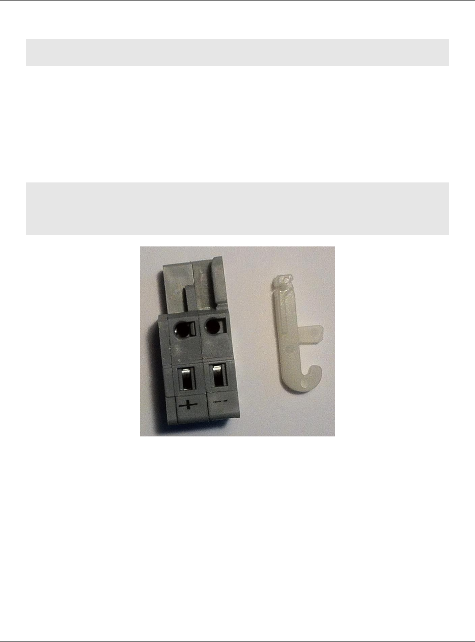
RLX2-IHx series ♦ 802.11a, b, g, n Appendix B - Radio Hardware
Industrial Hotspots User Manual
ProSoft Technology, Inc. Page 165 of 227
October 30, 2017
8.2 Radio Power Requirements (All other radios)
Note: The following instructions do not pertain to the RLX2-IHNF-W radio.
The RLX2-IHx series radios accept voltages between 10 and 24 VDC, with an
average power draw of less than 8 Watts. A detachable power connector comes
with the radio, as shown below. The connector terminals are labeled + (positive
DC connection) and - (DC ground connection).
You can use the AC-to-DC power supply adapter supplied with the optional RLX-
IHBTK Bench Test Kit to convert the input power. The DC power wires must be
less than 3 meters in length to meet regulatory requirements.
Warning: When wiring the power connector supplied with the radio, be sure to observe the proper
polarity markings on the power connector. Wiring the connector incorrectly can cause serious
damage to the radio which is not covered under the ProSoft Technology warranty.
The power connector (ProSoft Technology part number 002-0116) is shown on
the left in the photo above. Note the + and – polarity markings. The wire
installation tool (ProSoft part number 357-0061) shown on the right is helpful for
installing wires into the spring-loaded contacts inside power connector.
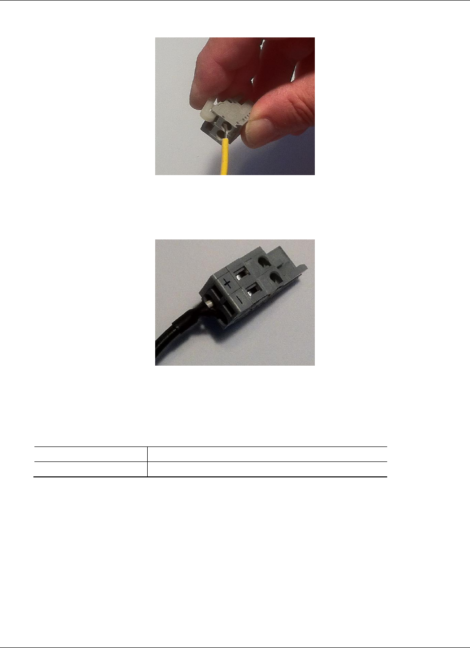
Appendix B - Radio Hardware RLX2-IHx series ♦ 802.11a, b, g, n
User Manual Industrial Hotspots
Page 166 of 227 ProSoft Technology, Inc.
October 30, 2017
To use the installation tool, insert it into the connector as shown below.
Press down on the installation tool to use it as a level to open the connector’s
contacts to insert a wire. A properly-wired power connector is shown below.
The RLX2-IHx series radios accept power from 802.3af Mode B or passive
Power over Ethernet (PoE) sources supplying 48VDC, with an average power
draw of less than 8 watts. ProSoft Technology offers the following passive PoE
injectors for use with the RLX2-IHx series radios:
POE-48I-AC
Power over Ethernet Injector, AC input
POE-48I-DC-DC
Power over Ethernet Injector, 9 to 36 VDC input voltage
The radio shall be installed by trained personnel only, as outlined in the
installation instructions provided with each radio.
The equipment shall be installed by a qualified installer/electrician. The
installer/electrician is responsible for obtaining a secured ground connection
between the lug terminal on the surge protector to a verified common ground
point using a minimum 6 AWG gauge wire. This must be done when
attaching power lines to the radio during installation.

RLX2-IHx series ♦ 802.11a, b, g, n Appendix B - Radio Hardware
Industrial Hotspots User Manual
ProSoft Technology, Inc. Page 167 of 227
October 30, 2017
Danger: A solid ground connection should be verified using a meter prior to applying power to the
radio. Failing to secure a proper ground could result in serious injury or death as a result of a
lightning strike.
Using Power over Ethernet (PoE) to power remote devices has several
advantages:
"Carrier Class" Power Over Ethernet system.
Power can be supplied over long distances, up to 300 feet.
Power can be available wherever network access is available.
The power supply can be centrally located where it can be attached to an un-
interruptible power supply.
You can easily power or reset the attached equipment from a remote
location.
There is no need to run additional power cabling to the device as power can
be supplied over the CAT5, CAT5E, or CAT6 Ethernet cable.
You can save on the cost of coax cable and reduce RF losses for remote
mounted radios.
Built-in Ethernet surge protection to prevent equipment damage.
Overload and short circuit protection.
8.3 Ethernet Cable Specifications
The recommended cable is Category 5 or better. A Category 5 cable has four
twisted pairs of wires, which are color-coded and cannot be swapped. The
module uses only two of the four pairs when running at 10 MBit or 100 MBit
speeds. All eight wires are used when running at 1000 MBit speeds.
Category 5e or better cable is recommended for 1000 MBit speeds.
The Ethernet port on the module is Auto-Sensing. Use either a standard
Ethernet straight-through cable or a crossover cable when connecting the
module to an Ethernet hub, a 10/100/1000 Base-T Ethernet switch, or directly
to a PC. The module detects the cable type and uses the appropriate pins to
send and receive Ethernet signals.
Ethernet cabling is similar to U.S. telephone cables, except that it has eight
conductors. Some hubs have one input that can accept either a straight-
through or crossover cable, depending on a switch position. In this case,
ensure the switch position and cable type agree.
Refer to Ethernet Cable Configuration (page 168) for a diagram of how to
configure Ethernet cables.
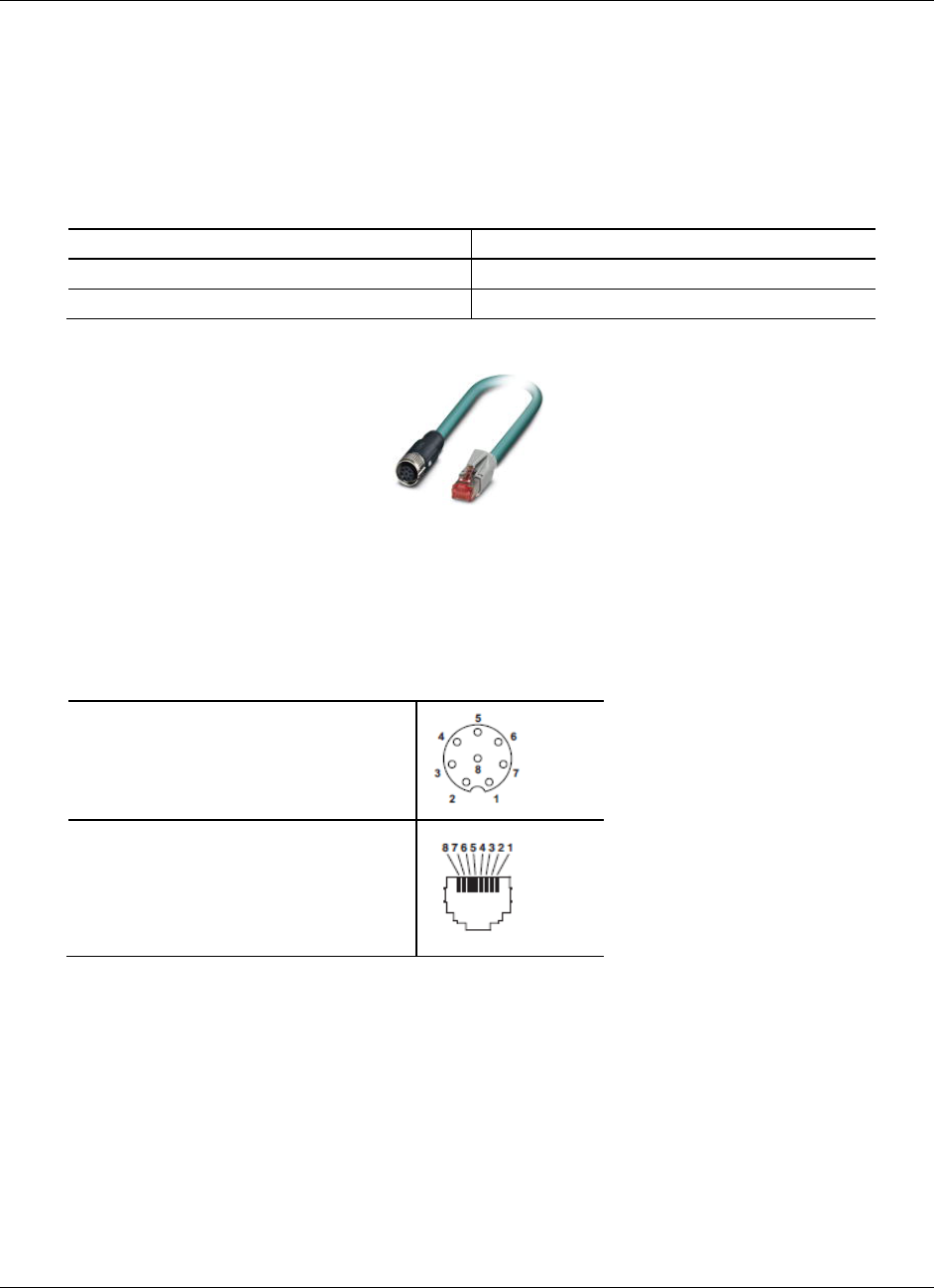
Appendix B - Radio Hardware RLX2-IHx series ♦ 802.11a, b, g, n
User Manual Industrial Hotspots
Page 168 of 227 ProSoft Technology, Inc.
October 30, 2017
8.4 Ethernet Cable Configuration
8.4.1 Ethernet Cable Configuration (RLX2-IHNF-W)
The RLX2-IHNF-W weatherproof radio uses cables with M12 connectors on one
end and RJ45 connectors on the other. These are Power over Ethernet (PoE)
cables that you can purchase directly from ProSoft Technology.
Description
ProSoft Part Number
Network Cable, 2m (7 ft) M12 to RJ45
CURJ45-M12-007
Network Cable, 10m (33 ft) M12 to RJ45
CURJ45-M12-033
This PoE cable contains an M12 (IP65, IP67) connector on one end that attaches
to the radio. The other end contains an RJ45 connector for a network connection
or power injector.
Pin Assignments
M12 socket, 8-pos, A-coded, female
RJ45 pin assignment
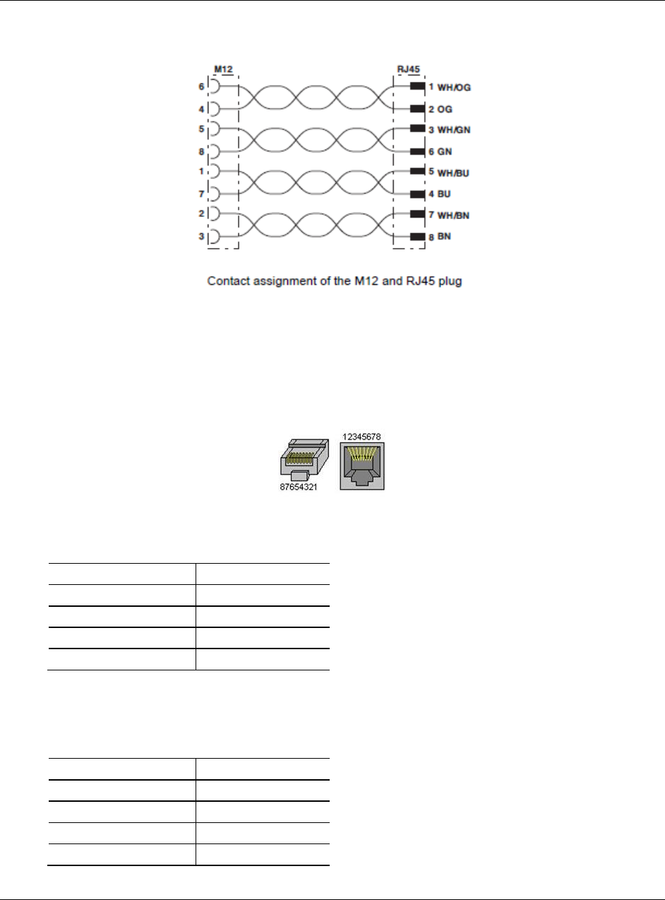
RLX2-IHx series ♦ 802.11a, b, g, n Appendix B - Radio Hardware
Industrial Hotspots User Manual
ProSoft Technology, Inc. Page 169 of 227
October 30, 2017
Circuit Diagram
8.4.2 Ethernet Cable Configuration (all other radios)
The RLX2-IHx series radios (except the RLX2-IHNF-W weatherproof radio) use
Ethernet cable. A diagram of the pin assignments appears below.
Straight-Though Cable
RJ-45 Pin
RJ-45 Pin
1 Rx+
1 Tx+
2 Rx-
2 Tx-
3 Tx+
3 Rx+
6 Tx-
6 Rx-
Crossover Cable
RJ-45 Pin
RJ-45 Pin
1 Rx+
3 Tx+
2 Rx-
6 Tx-
3 Tx+
1 Rx+
6 Tx-
2 Rx-

Appendix B - Radio Hardware RLX2-IHx series ♦ 802.11a, b, g, n
User Manual Industrial Hotspots
Page 170 of 227 ProSoft Technology, Inc.
October 30, 2017

RLX2-IHx series ♦ 802.11a, b, g, n Appendix C - RLX2-IHx 5 GHz Radio DFS Support
Industrial Hotspots User Manual
ProSoft Technology, Inc. Page 171 of 227
October 30, 2017
9 Appendix C - RLX2-IHx 5 GHz Radio DFS
Support
In This Chapter
DFS Radio Operations ........................................................................ 171
Some channels in the 5 GHz band are shared with radar and must adhere to
Dynamic Frequency Selection (DFS) rules. If the radio detects the presence of
radar on its operating frequency, it must automatically change to another
frequency.
Note: This applies only to radios that can operate at frequencies in the 5 GHz band.
9.1 DFS Radio Operations
If radar is detected on an operating channel, transmissions must cease within the
required Channel Closing Transmission Time, and must move to a new channel
within the required Channel Move Time. Before transmitting on a new DFS
channel that has not been previously checked for radar, the RLX2-IHx series
radio must monitor the channel for the Channel Availability Check Time before
transmitting. Operations cannot return to a channel where radar was detected for
at least the Non-Occupancy Period. The values for these parameters are noted
in the table below:
Parameter
FCC Value
ETSI Value
ETSI Value
5.600 to 5.650 GHz
(Channels 120, 124, &
128)
Channel Availability
Check Time
60 seconds
60 seconds
10 minutes
Channel Move Time
10 seconds (12 seconds
for "long pulse" radar
10 seconds
10 seconds
Channel Closing
Transmission Time
200 milliseconds (plus
up to 60 milliseconds
over 10 seconds)
1 second
1 second
Non-Occupancy Period
30 minutes
30 minutes
30 minutes

Appendix C - RLX2-IHx 5 GHz Radio DFS Support RLX2-IHx series ♦ 802.11a, b, g, n
User Manual Industrial Hotspots
Page 172 of 227 ProSoft Technology, Inc.
October 30, 2017
If a Master radio detects radar, it issues a channel change announcement to all
Client and Repeater radios in the network. It then moves to a new channel within
the Channel Move Time. (Typically, this move time is 500 milliseconds or less.) If
the selected channel was not previously checked for the presence of radar, the
Master radio must do so for the Channel Availability Check Time before it can
begin to transmit. If the newly-selected channel is not a DFS channel, or if the
channel was previously monitored for radar since the radio was powered on,
transmissions can begin immediately.
During the Channel Availability Check Time, a radio blinks all three amber Signal
Strength LEDS approximately once per second. If radar is detected on the new
channel during the Channel Availability Check Time, the Master radio selects
another channel and begins the process again.
If a Client or Repeater radio detects radar, in addition to stopping data
transmission, must notify its parent of the presence of radar. Each unit receiving
a radar notification from a child unit treats it the same as if it had detected radar
itself and acts accordingly. Thus radar notifications always reach the Master
radio which causes a channel change order to be issued.
After a Master radio successfully selects a DFS channel, Repeater or Client
radios connect to the Master and scan for radar for an additional 60 seconds
(Channel Availability Check Time). If a chain of Repeater radios ultimately
connects to a Master radio using a DFS channel, the time to connect is 60
seconds for each Repeater radio in the chain as DFS channels are initially
scanned for radar transmissions.
9.1.1 Selecting a DFS 5 GHz Channel
For [ModelNumber] Master radios operating in the 5 GHz band, you can select a
DFS channel, or let the radio automatically select the DFS channel. DFS
channels are a 5 GHz radio parameter only, and apply to all RLX2-IHx series
radios except the RLX2-IHG.
Note: In some cases, the radio may select a channel in the 5 GHz Upper Band if it does not find an
open channel in the 5 GHz DFS Band.
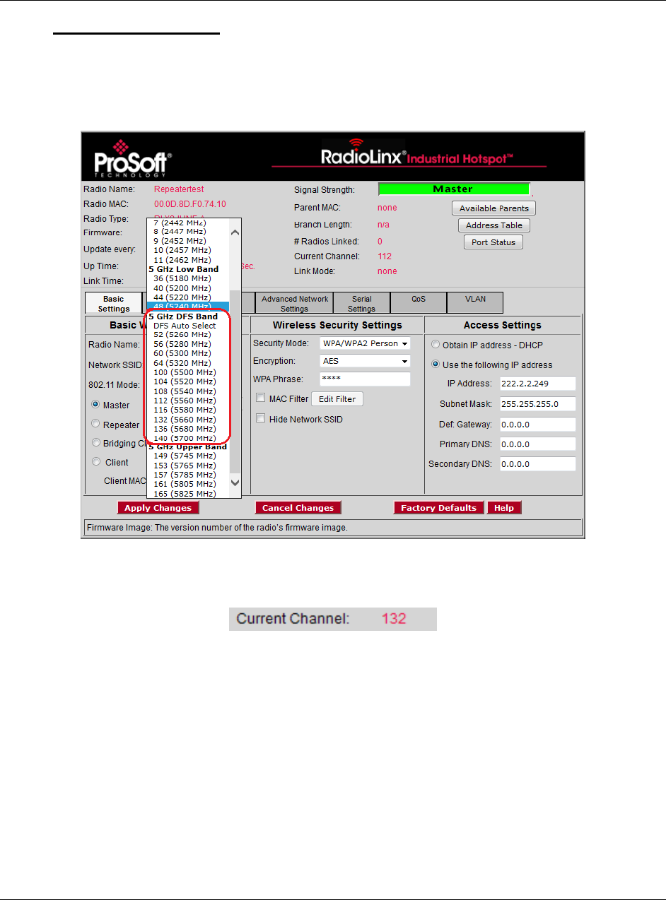
RLX2-IHx series ♦ 802.11a, b, g, n Appendix C - RLX2-IHx 5 GHz Radio DFS Support
Industrial Hotspots User Manual
ProSoft Technology, Inc. Page 173 of 227
October 30, 2017
To Select a DFS Channel
In the Radio Configuration / Diagnostic Utility, on the BASIC SETTINGS tab, in the
BASIC WIRELESS SETTINGS group, select the starting DFS channel. If the radio
detects a radar signal on this channel, it changes the channel as described in
DFS Radio Operations (page 171).
The actual channel in operation is always shown in the CURRENT CHANNEL
display.
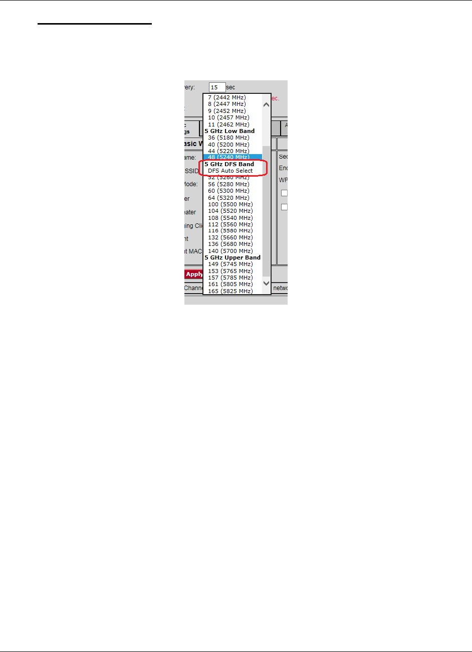
Appendix C - RLX2-IHx 5 GHz Radio DFS Support RLX2-IHx series ♦ 802.11a, b, g, n
User Manual Industrial Hotspots
Page 174 of 227 ProSoft Technology, Inc.
October 30, 2017
To Use DFS Auto Select
In the Radio Configuration / Diagnostic Utility, on the BASIC SETTINGS tab, in the
BASIC WIRELESS SETTINGS group, select the Master radio channel DFS Auto
Select.
With this selection the radio randomly selects a DFS channel for operation. The
actual channel in operation is always shown in the CURRENT CHANNEL display.

RLX2-IHx series ♦ 802.11a, b, g, n Appendix D - RLX2-IHx series Virtual LAN (VLAN) Functionality
Industrial Hotspots User Manual
ProSoft Technology, Inc. Page 175 of 227
October 30, 2017
10 Appendix D - RLX2-IHx series Virtual LAN
(VLAN) Functionality
In This Chapter
Transparent Support of VLAN Tags (802.1Q) ..................................... 176
Port/Radio-based VLAN Tagging with Managed Switches .................. 177
Port/Radio-based VLAN Tagging without Managed Switches ............. 178
Virtual Local Area Networks (VLANs) are typically used to segment core network
components and network access rules. A VLAN provides the equivalent of a
wired patch panel through software (packet filtering) rather than hardware
(physical wires).
Constraining data to a particular Virtual LAN requires that the radio tag packets
with a VLAN identifier. VLAN tagging simply adds extra information in the packet
header of Ethernet frames so VLAN-enabled switches know how to pass along
the data.
The RLX2-IHx series radios (version 33 and later) provide:
Transparent support of VLAN tags (802.1Q)
Port/Radio-based VLAN tagging with Managed Switches
Port/Radio-based VLAN tagging without Managed Switches
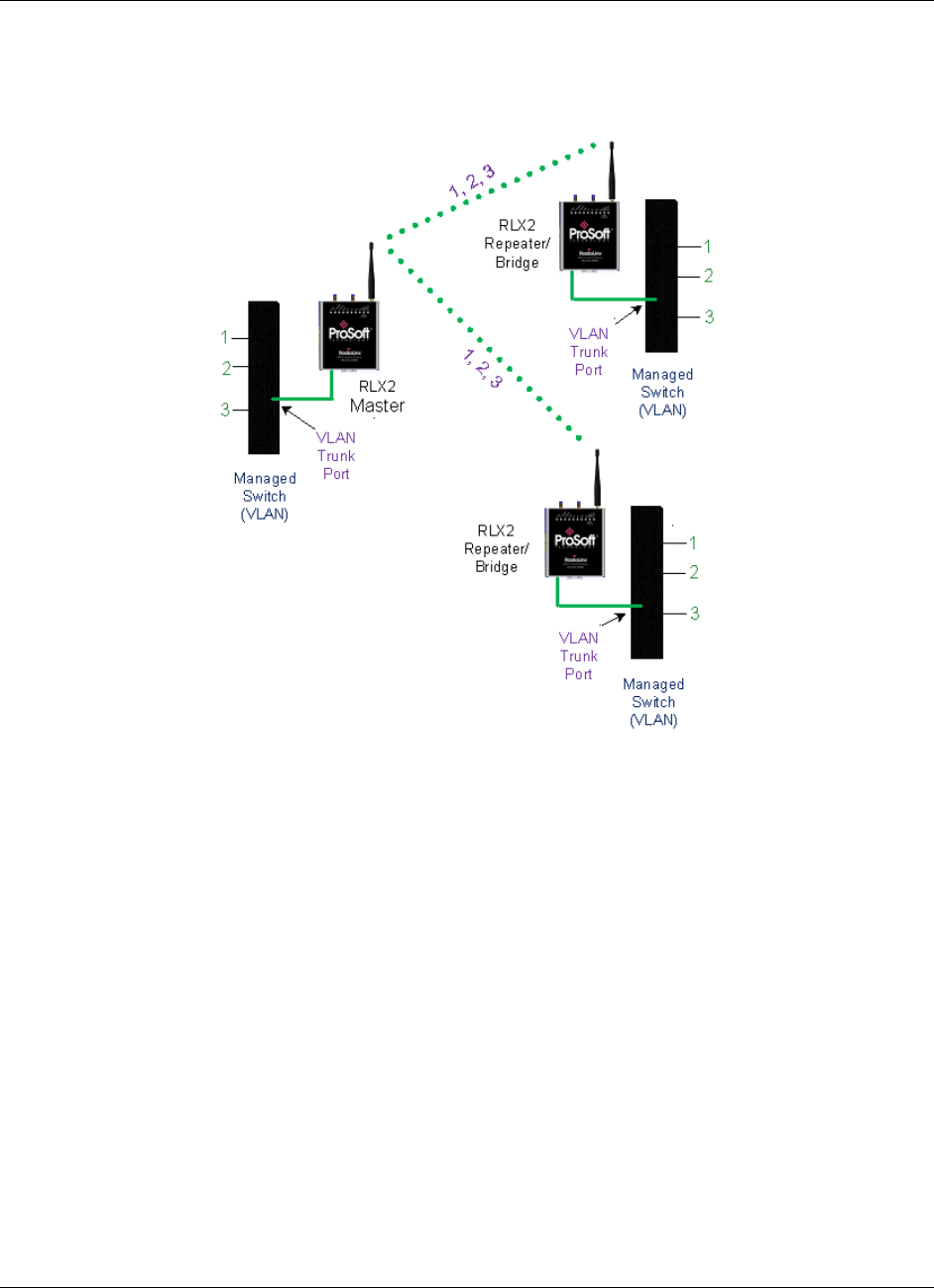
Appendix D - RLX2-IHx series Virtual LAN (VLAN) Functionality RLX2-IHx series ♦ 802.11a, b, g, n
User Manual Industrial Hotspots
Page 176 of 227 ProSoft Technology, Inc.
October 30, 2017
10.1 Transparent Support of VLAN Tags (802.1Q)
The following provides an example of transparent communication between
Managed Switches using VLAN trunking.
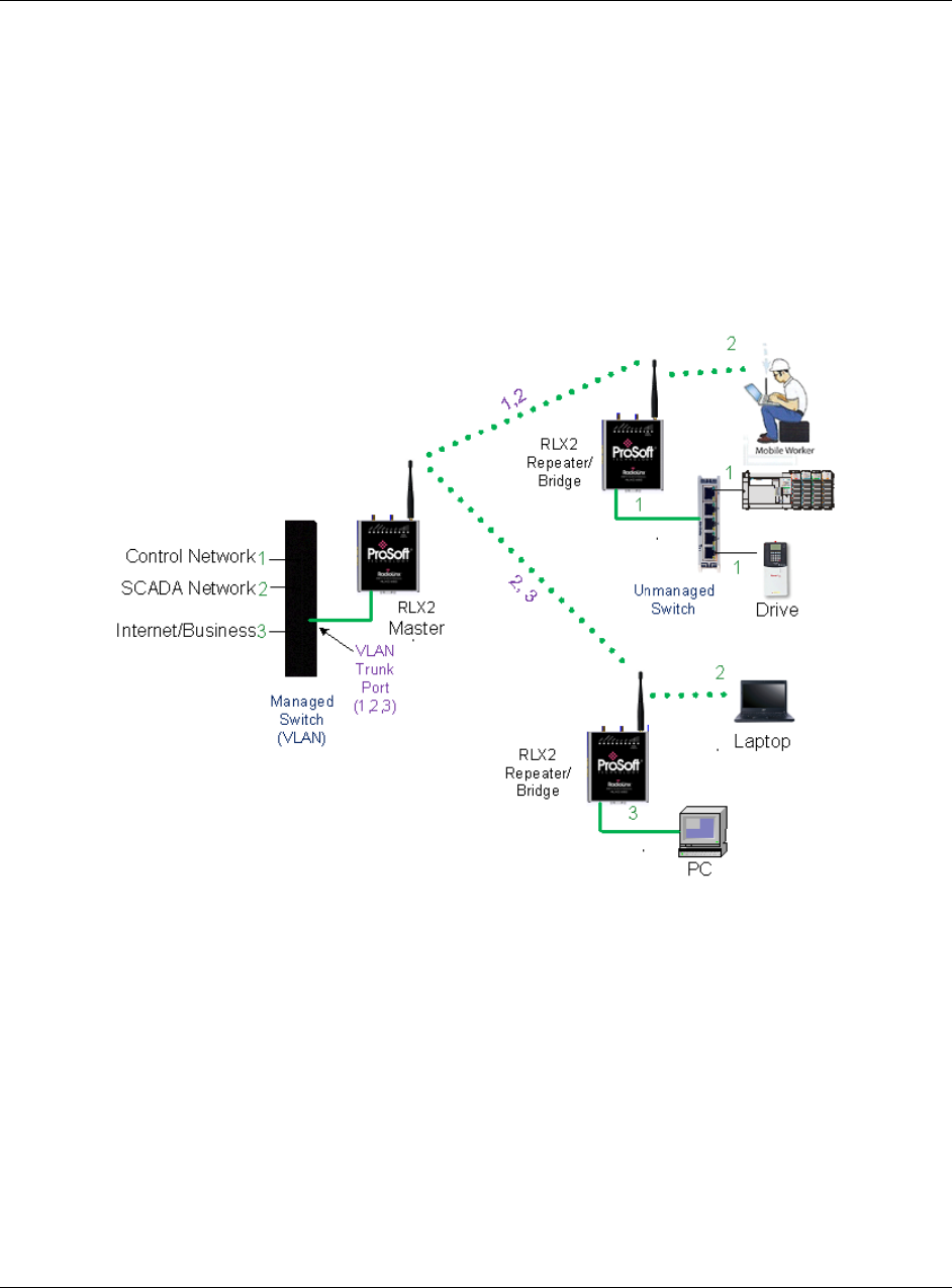
RLX2-IHx series ♦ 802.11a, b, g, n Appendix D - RLX2-IHx series Virtual LAN (VLAN) Functionality
Industrial Hotspots User Manual
ProSoft Technology, Inc. Page 177 of 227
October 30, 2017
10.2 Port/Radio-based VLAN Tagging with Managed Switches
In this example, the network has three VLANs (capacity for 8). Each VLAN has
access to a Managed Switch pre-configured to assign each VLAN to a specific
port. The Radio supporting the Managed Switch passes on the 802.1Q frames.
This example shows support for Radio to Radio VLANs using one or more Trunk
Links.
PLC, Drive, and HMI communicate on VLAN 1 and with the Control Network
(same subnet).
Mobile worker communicates to the SCADA network only (VLAN 2). The
laptop communicates to Internet/Business Network only (VLAN 3).
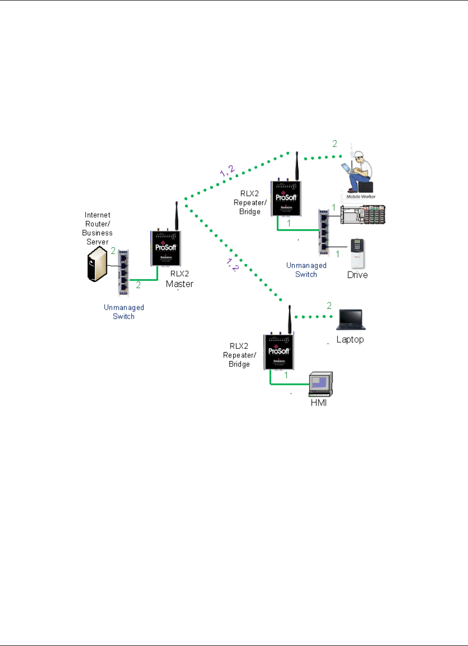
Appendix D - RLX2-IHx series Virtual LAN (VLAN) Functionality RLX2-IHx series ♦ 802.11a, b, g, n
User Manual Industrial Hotspots
Page 178 of 227 ProSoft Technology, Inc.
October 30, 2017
10.3 Port/Radio-based VLAN Tagging without Managed Switches
In the following example, the network has three VLANs (capacity for 8). Each
VLAN has access to a specific Radio port. The Radio supporting the Managed
Switch passes on the 802.1Q frames. The wireless network also supports Radio
to Radio VLANs using one or more Trunk Links.
PLC, Drive & HMI communicate on one VLAN on the same subnet.
Mobile Worker/Laptop communicate with a fixed server on VLAN 2 (separate
subnet).

RLX2-IHx series ♦ 802.11a, b, g, n Appendix E - EtherNet/IP and Modbus TCP/IP Support
Industrial Hotspots User Manual
ProSoft Technology, Inc. Page 179 of 227
October 30, 2017
11 Appendix E - EtherNet/IP and Modbus TCP/IP
Support
In This Chapter
Modbus TCP/IP Server Support .......................................................... 179
EtherNet/IP™ Server Support ............................................................. 181
You can get diagnostic and status information from the RLX2-IHx series radio by
querying the radio using either the Ethernet/IP or Modbus TCP/IP protocols.
11.1 Modbus TCP/IP Server Support
You can use a Modbus TCP/IP client to poll the RLX2-IHx series radio for
diagnostic and status information. The Modbus TCP/IP server in the radio
monitors port 502 and port 2000, and responds to requests from the port eth0
(Ethernet port) or ppp0 (Point-to-Point Protocol). PPP is a data link layer protocol
that establishes a connection between two nodes.
The radio supports up to five concurrent Modbus TCP/IP client connections.

Appendix E - EtherNet/IP and Modbus TCP/IP Support RLX2-IHx series ♦ 802.11a, b, g, n
User Manual Industrial Hotspots
Page 180 of 227 ProSoft Technology, Inc.
October 30, 2017
11.1.1 Modbus Memory Map Diagnostic Information
The topic lists the is the Modbus register addresses that you use to read the
RLX2-IHx series radio diagnostic and status information.
Name
Data Type
Access
Modbus Register
RLX2_Diag.SSID
SINT[32]
Read
30001 – 30016
RLX2_Diag.IPAddress
SINT[4]
Read
30017 – 30018
RLX2_Diag.MACAddress
SINT[6]
Read
30019 – 30021
RLX2_Diag.NeworkMode
SINT
Read
30022
RLX2_Diag.ConnectionState
SINT
Read
30023
RLX2_Diag.SignalStrength
INT
Read
30024
RLX2_Diag.Channel
SINT
Read
30025
RLX2_Diag.WEP
SINT
Read
30026
RLX2_Diag.Flags
DINT
Read
30027 – 30028
RLX2_Diag.MasterMACAddress
SINT[6]
Read
30029 – 30031
RLX2_Diag.HopCount
SINT
Read
30032
RLX2_DiagStatus
SINT
Read
30033
RLX2_Diag.NumAssociations
INT
Read
30034
RLX2_Diag.NumBridgeAssocs
INT
Read
30035
RLX2_Diag.TxRadioThroughput
INT
Read
30036
RLX2_Diag.RxRadioThroughput
INT
Read
30037
RLX2_Diag.Uptime
DINT
Read
30038 – 30039
RLX2_Diag.LinkTime
DINT
Read
30040 – 30041
RLX2_Diag.TxPktThput
DINT
Read
30042 – 30043
RLX2_Diag.RxPktThput
DINT
Read
30044 – 30045
RLX2_Diag.ModuleName
SINT[32]
Read
30046 – 30061
RLX2_Diag.ProductName
SINT[32]
Read
30062 – 30077
RLX2_Diag.ImageVerStr
SINT[28]
Read
30078 – 30091
RLX2_Diag.tx_good
DINT
Read
30092 - 30093
RLX2_Diag.rx_good
DINT
Read
30094 – 30095
RLX2_Diag.tx_bad
DINT
Read
30096 – 30097
RLX2_Diag.rx_bad
DINT
Read
30098 – 30099
RLX2_Diag.tx_directed_frames
DINT
Read
30100 – 30101
RLX2_Diag.tx_multicast_frames
DINT
Read
30102 – 30103
RLX2_Diag.tx_broadcast_frames
DINT
Read
30104 – 30105
RLX2_Diag.rx_directed_frames
DINT
Read
30106 – 30107
RLX2_Diag.rx_multicast_frames
DINT
Read
30108 – 30109
RLX2_Diag.rx_broadcast_frames
DINT
Read
30110 – 30111
RLX2_Diag.rx_crc_error
DINT
Read
30112 - 30113
Modbus Function Code 4 (Read Input Registers(3X)) is supported.

RLX2-IHx series ♦ 802.11a, b, g, n Appendix E - EtherNet/IP and Modbus TCP/IP Support
Industrial Hotspots User Manual
ProSoft Technology, Inc. Page 181 of 227
October 30, 2017
11.2 EtherNet/IP™ Server Support
The topic lists the is the CIP™ object definition that you use to read the RLX2-
IHx series radio diagnostic and status information.
Class ID: 0xA1 (161)
Number of Instances: 1
CIP Data Tag Name
Data Type
Access
RLX2_Diag.SSID
SINT[32]
Read
RLX2_Diag.IPAddress
SINT[4]
Read
RLX2_Diag.MACAddress
SINT[6]
Read
RLX2_Diag.NetworkMode
SINT
Read
RLX2_Diag.ConnectionState
SINT
Read
RLX2_Diag.SignalStrength
INT
Read
RLX2_Diag.Channel
SINT
Read
RLX2_Diag.WEP
SINT
Read
RLX2_Diag.Flags
DINT
Read
RLX2_Diag.MasterMACAddress
SINT[6]
Read
RLX2_Diag.HopCount
SINT
Read
RLX2_Diag.Status
SINT
Read
RLX2_Diag.NumAssociations
INT
Read
RLX2_Diag.NumBridgeAssocs
INT
Read
RLX2_Diag.TxRadioThroughput
INT
Read
RLX2_Diag.Uptime
INT
Read
RLX2_Diag.Linktime
DINT
Read
RLX2_Diag.TxPktThput
DINT
Read
RLX2_Diag.RxPktThput
DINT
Read
RLX2_Diag.ModuleName
DINT
Read
RLX2_Diag.ProductName
SINT[32]
Read
RLX2_Diag.ImageVerStr
SINT[32]
Read
RLX2_Diag.tx_good
SINT[28]
Read
RLX2_Diag.rx_good
DINT
Read
RLX2_Diag.tx_bad
DINT
Read
RLX2_Diag.rx_bad
DINT
Read
RLX2_Diag.tx_directed_frames
DINT
Read
RLX2_Diag.tx_multicast_frames
DINT
Read
RLX2_Diag.tx_broadcast_frames
DINT
Read
RLX2_Diag.rx_directed_frames
DINT
Read
RLX2_Diag.rx_multicast_frames
DINT
Read
RLX2_Diag.rx_broadcast_frames
DINT
Read
RLX2_Diag.rx_crc_err
DINT
Read

Appendix E - EtherNet/IP and Modbus TCP/IP Support RLX2-IHx series ♦ 802.11a, b, g, n
User Manual Industrial Hotspots
Page 182 of 227 ProSoft Technology, Inc.
October 30, 2017

RLX2-IHx series ♦ 802.11a, b, g, n Appendix F - Master Channel-Frequency Table
Industrial Hotspots User Manual
ProSoft Technology, Inc. Page 183 of 227
October 30, 2017
12 Appendix F - Master Channel-Frequency Table
The following table shows the channels/frequencies available in each RLX2-IHx
series radio. Note that radios configured for FCC and ETSI regulatory domains
do not have the same channels available. Also, some channels may have usage
or power restrictions (for example, indoor or outdoor) in some locations.
FCC
RLX2-XXX-A versions
ETSI
RLX2-XXX-E versions
Channel
Number
Center
Frequency
(MHz)
IHA
IHG
IHNF
IHW
IHA
IHG
IHNF
IHW
1
2412
2
2417
3
2422
4
2427
5
2432
6
2437
7
2442
8
2447
9
2452
10
2457
11
2462
12
2467
13
2472
36
5180
40
5200
44
5220
48
5240
52 (DFS)
5260
56 (DFS)
5280
60 (DFS)
5300
64 (DFS)
5320
100 (DFS)
5500
104 (DFS)
5520
108 (DFS)
5540
112 (DFS)
5560
116 (DFS)
5580
120 (DFS)
5600

Appendix F - Master Channel-Frequency Table RLX2-IHx series ♦ 802.11a, b, g, n
User Manual Industrial Hotspots
Page 184 of 227 ProSoft Technology, Inc.
October 30, 2017
124 (DFS)
5620
128 (DFS)
5640
132 (DFS)
5660
136 (DFS)
5680
140 (DFS)
5700
149
5745
153
5765
157
5785
161
5805
165
5825

RLX2-IHx series ♦ 802.11a, b, g, n Appendix G - Antenna Configuration
Industrial Hotspots User Manual
ProSoft Technology, Inc. Page 185 of 227
October 30, 2017
13 Appendix G - Antenna Configuration
In This Chapter
Antennas ............................................................................................. 185
Antenna Types .................................................................................... 189
RLX2-IHx series Approved Antennas .................................................. 191
Antenna Location, Spacing, and Mounting .......................................... 194
13.1 Antennas
There are several important electrical characteristics that you must consider
when selecting antennas for a RLX2-IHx series radio.
Antenna pattern
Antenna gain
Antenna polarity
Antenna location, spacing, and mounting
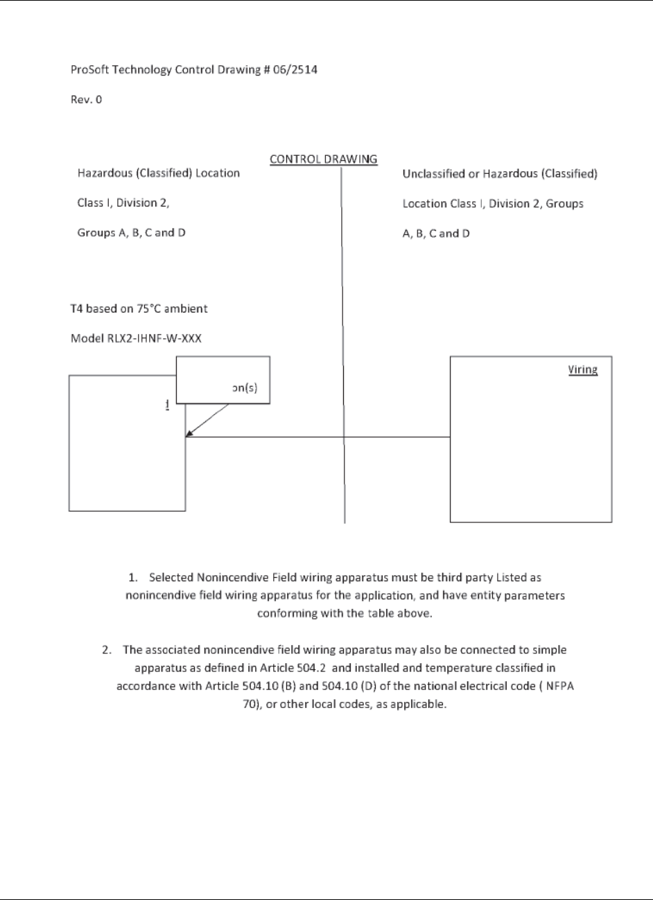
Appendix G - Antenna Configuration RLX2-IHx series ♦ 802.11a, b, g, n
User Manual Industrial Hotspots
Page 186 of 227 ProSoft Technology, Inc.
October 30, 2017
13.1.1 Control Drawing
RLX2-IHx series ♦ 802.11a, b, g, n Appendix G - Antenna Configuration
Industrial Hotspots User Manual
ProSoft Technology, Inc. Page 187 of 227
October 30, 2017
13.1.2 Antenna Pattern
Wireless devices transfer Information using electromagnetic energy radiated by
one antenna and received by another antenna. The power radiated by most
antennas is not uniform in all directions and has varying intensities. The power
radiated by the antenna in various directions is called the pattern of the antenna.
Mount each antenna so that the direction of strongest radiation points toward the
other antenna or antennas with which it will exchange signals.
Complete antenna patterns are three-dimensional. Often only a two-dimensional
slice of the pattern is shown when all the antennas of interest are located in
roughly the same horizontal plane instead of above or below one another. A slice
taken in a horizontal plane through the center (or looking down onto the pattern)
is called the azimuth pattern. A slice taken in a vertical plan from the side is
called the elevation pattern.

Appendix G - Antenna Configuration RLX2-IHx series ♦ 802.11a, b, g, n
User Manual Industrial Hotspots
Page 188 of 227 ProSoft Technology, Inc.
October 30, 2017
An antenna pattern with equal or nearly equal intensity in all directions is called
omnidirectional. In two dimensions, an omnidirectional pattern appears as a
circle (in three dimensions, an omnidirectional antenna pattern is a sphere, but
no antenna has a true omnidirectional pattern in three dimensions). An antenna
is considered omnidirectional if one of its two dimensional patterns, either
azimuth or elevation pattern, is omnidirectional.
Beamwidth is an angular measurement of how strongly the power is
concentrated in a particular direction. Beamwidth is a three dimensional quantity
but can be broken into two-dimensional slices just like the antenna pattern. The
beamwidth of an omnidirectional pattern is 360 degrees because the power is
equal in all directions.
13.1.3 Antenna Gain
Antenna gain is a measure of how strongly an antenna radiates in its direction of
maximum intensity compared to the strength of the radiation if the same power
were applied to an omnidirectional antenna (one that radiated all of its power
equally in all directions). In the antenna pattern, the gain is the distance to the
furthest point on the pattern from the origin. For an omnidirectional pattern, the
gain is 1, or equivalently 0 dB. The higher the antenna gain, the narrower the
beamwidth, and vice versa.
The amount of power received by the receiving antenna is proportional to the
transmitter power multiplied by the transmit antenna gain, multiplied by the
receiving antenna gain. Therefore, you can make trade-offs between the
antennas' gain and transmitting power. For example, doubling the gain of one of
the antennas has the same effect as doubling the transmitting power. Doubling
the gain for both antennas has the same effect as quadrupling the transmitting
power.
13.1.4 Antenna Polarity
Antenna polarization refers to the direction in which the electromagnetic field
lines point as energy radiates away from the antenna. In general, the polarization
is elliptical. The simplest and most common form of this elliptical polarization is a
straight line, or linear polarization.
An antenna only receives the portion of the transmitted power that has the same
polarization as the receiving antenna polarization. For example:
If the transmitting antenna polarization is in the vertical direction (vertical
polarization), and the receiving antenna also has vertical polarization, the
maximum amount of power possible is received.
On the other hand, if the transmit antenna has vertical polarization and the
receiving antenna has horizontal polarization, no power should be received. If
the two antennas have linear polarizations oriented at 45° to each other, only
half of the possible maximum power is received.
RLX2-IHx series ♦ 802.11a, b, g, n Appendix G - Antenna Configuration
Industrial Hotspots User Manual
ProSoft Technology, Inc. Page 189 of 227
October 30, 2017
13.2 Antenna Types
Antenna types used with a RLX2-IHx series radio include whip, collinear array,
yagi array, and parabolic reflector. See the RLX2-IHx series Approved Antennas
(page 191) section for other types of approved antennas.
13.2.1 Whip Antennas
For RLX2-IHx series radios, use a 1/2 wave straight whip antennal or a 1/2 wave
articulating whip (2 dBi) antenna. These antennas are the most common type in
use today.
They are approximately 5 inches long, and are likely to be connected directly
to the client radio enclosure.
These antennas do not require a ground plane.
Articulating antennas and non-articulating antennas work in the same way.
An articulating antenna bends at the connection as shown in the image
below.
13.2.2 Collinear Array Antennas
A collinear array antenna is typically composed of several linear antennas
stacked on top of each other. The more stacked elements it has, the longer it is,
and the more gain it has. The signal is connected at one end.

Appendix G - Antenna Configuration RLX2-IHx series ♦ 802.11a, b, g, n
User Manual Industrial Hotspots
Page 190 of 227 ProSoft Technology, Inc.
October 30, 2017
The antenna pattern is torroidal. Its azimuthal beamwidth is 360°
(omnidirectional). Its vertical beamwidth depends on the number of
elements/length, and more elements produce a narrower beamwidth.
The antenna gain also depends on the number of elements/length, and more
elements produce a higher gain. The typical gain for this antenna is 5 to 10
dBi.
The antenna polarity is linear, or parallel to the length of the antenna.
13.2.3 Yagi Array Antenna
A yagi array antenna is composed of an array of linear elements, each parallel to
one another and attached perpendicular to, and along the length of, a metal
boom. The signal is connected to only one of the elements. Elements on one
side of the connected element are longer and act as reflectors; elements on the
other side are shorter and act as directors. This causes the antenna to radiate in
a beam out of the end with the shorter elements. The pattern depends on the
overall geometry, including the number of elements, element spacing, element
length, and so on. Sometimes the antenna is enclosed in a protective tube hiding
the actual antenna geometry (as shown in the image below).
The antenna pattern is a beam pointed along the boom toward the end with
the shorter elements. The beamwidth varies with antenna geometry but
generally is proportional to the length (where longer length produces a
narrower beam).
The antenna gain varies with antenna geometry but generally is proportional
to the length (where longer length produces higher gain). Typical values are 6
to 15dBi.
The antenna polarity is Linear (parallel to the elements, perpendicular to the
boom).

RLX2-IHx series ♦ 802.11a, b, g, n Appendix G - Antenna Configuration
Industrial Hotspots User Manual
ProSoft Technology, Inc. Page 191 of 227
October 30, 2017
13.2.4 Parabolic Reflector Antennas
A parabolic reflector antenna consists of a parabolic shaped dish and a feed
antenna located in front of the dish. The feel antenna radiates power toward the
reflector. Due to the parabolic shape, the reflector concentrates the radiation into
a narrow pattern, resulting in a beam with high gain.
The antenna pattern is a beam pointed away from the concave side of the
dish. Beamwidth and antenna gain vary with the size of the reflector and the
antenna construction. Typical gain values are 15 to 30 dBi.
The antenna polarity depends on the feed antenna polarization.
13.3 RLX2-IHx series Approved Antennas
If you are located In the U.S. and Canada, use antennas that are specifically
approved by the U.S. Federal Communications Commission (FCC) and Industry
Canada for use with the RLX2-IHx series radios. Contact ProSoft Technology or
visit www.prosoft-technology.com for a current list of approved antennas.
Antenna selection depends on whether the bi-directional amplifier is being used
or not. For each approved antenna, there is a specified minimum distance the
antennas must be separated from users for safe exposure limits, according to
FCC part 2.1091.

Appendix G - Antenna Configuration RLX2-IHx series ♦ 802.11a, b, g, n
User Manual Industrial Hotspots
Page 192 of 227 ProSoft Technology, Inc.
October 30, 2017
13.3.1 Approved Antenna Table
Use the following approved antennas when the RLX2-IHx series radio module is
connected directly to an antenna. See Approved Antennas with Power Amp
(page 193) for a table of approved antennas with bi-directional power amplifiers.
Type
Pattern
Gain
Connector
Size (cm)
Min. distance
from Body
1/2 Wave
Omni
2 dB
SMA-RP
7H x 1.5
20 cm
1/2 Wave art.
Omni
2 dB
SMA-RP
10H x 1.0
20 cm
Collinear Array
Omni
3 dB
SMA-RP
6H x 3.0
20 cm
Collinear Array, art.
Omni
5 dB
SMA-RP
19H x 1.0
20 cm
Collinear Array
Omni
5 dB
SMA-RP
19H x 1.0
20 cm
Collinear Array
Omni
8 dB
N-RP
43H x 1.6
20 cm
Collinear Array
Omni
9 dB
N-RP
43H x 1.6
20 cm
Collinear Array
Omni
12 dB
N-RP
106H x 4.0
25 cm
Patch
Directional
8 dB
SMA-RP
15.0H x 15.0
20 cm
Patch
Directional
11 dB
SMA-RP
22H x 12.7
22 cm
Patch
Directional
13 dB
N-RP
22H x 22
28 cm
Patch*
Directional
19 dB
N-RP
15.5 x 15.5
57 cm
Yagi
Directional
14 dB
N-RP
81L x 9.0
28 cm
Parabolic*
Directional
15 dB
N-RP
40H x 51W x 25D
36 cm
Parabolic*
Directional
19 dB
N-RP
58H x 66W x 26D
57 cm
Parabolic*
Directional
24 dB
N-RP
78H x 96W x 29D
100 cm
* Only allowed in a point-to-point network.
13.3.2 Approved Antennas in Europe/CE
In Europe/CE, the gain of the antenna connected to the RLX2-IHx series radio
main antenna port, minus the antenna cable loss, must be less than 4 dB to stay
below the 100-mW EIRP transmit power limit.
The AUX port on the radio is only used to receive; it never transmits.
Note: In France, the user is responsible for ensuring that the selected frequency channels comply
with French regulatory standards. At the time of this printing, only channels 10 through 13 can be
used in France.

RLX2-IHx series ♦ 802.11a, b, g, n Appendix G - Antenna Configuration
Industrial Hotspots User Manual
ProSoft Technology, Inc. Page 193 of 227
October 30, 2017
13.3.3 Approved Antennas in Mexico
The gain of the antenna connected to the RLX2-IHx series radio main antenna
port, minus the antenna cable loss, must be less than 12 dB to stay below the
650-mW EIRP transmit power limit.
Note: In Mexico, the user is responsible for ensuring that the selected frequency channels comply
with Mexican regulatory standards. At the time of this printing, only channels 9 through 11 can be
used outdoors (1 through 8 cannot); however, channels 1 through 11 can all be used indoors.
13.3.4 Approved Antennas with Power Amp
When the RLX2-IHx series radio is used in conjunction with the amplifier, the
antennas are limited to antennas listed in the following table.
Type
Pattern
Gain
Connector
Size (cm)
Min. distance from
Body
1/2 Wave
Omni
2 dB
SMA-RP
7H x 1.5
20 cm
1/2 Wave art.
Omni
2 dB
SMA-RP
10H x 1.0
20 cm
Collinear Array
Omni
3 dB
SMA-RP
6H x 3.0
20 cm
Collinear Array, art.
Omni
5 dB
SMA-RP
19H x 1.0
20 cm
Collinear Array
Omni
5 dB
SMA-RP
19H x 1.0
20 cm
Collinear Array
Omni
8 dB
N-RP
43H x 1.6
20 cm
Collinear Array
Omni
9 dB
N-RP
43H x 1.6
20 cm
Collinear Array*
Omni
12 dB
N-RP
106H x 4.0
25 cm
Patch
Directional
8 dB
SMA-RP
15.0H x 15.0
20 cm
Patch*
Directional
11 dB
SMA-RP
22H x 12.7
20 cm
Patch*
Directional
13 dB
N-RP
22H x 22
28 cm
Yagi*
Directional
14 dB
N-RP
81L x 9.0
28 cm
* Only allowed in a point-to-point network.

Appendix G - Antenna Configuration RLX2-IHx series ♦ 802.11a, b, g, n
User Manual Industrial Hotspots
Page 194 of 227 ProSoft Technology, Inc.
October 30, 2017
13.4 Antenna Location, Spacing, and Mounting
Consider the following points regarding RLX2-IHx series radio antenna location,
spacing, and mounting:
When placing antennas, ensure a clear line of sight between the Master
radio's antenna and all of the other radio antennas.
If the site contains obstructing terrain or structures, mount the antenna on a
tower or rooftop to provide a line-of-sight path. This line-of-sight consideration
becomes more important as the transmission path becomes longer.
Mount the antennas as high off the ground as is practical for greater range.
Mount the antennas away from massive structures. For example, radio
signals bounce off metal walls, which can compromise a clear signal.
Mount the antennas and install radios away from sources of RF interference.
Use the shortest possible antenna cable length. Signals lose power over the
length of the cable.
Choose antennas that are appropriate for the network's intended function.
If antennas are on radios on the same network, mount them with matching
polarity. If the antennas are on separate networks, mount them with different
antenna polarity; for example, mount one antenna vertically and the other
horizontally.
Space radios at least three feet (one meter) apart so they do not overload
each other. If radio antennas must be near each other:
o Mount omnidirectional antennas directly above each other.
o Position directional antennas so they do not point at nearby antennas:
place antennas side by side if they point in the same direction; place
antennas back to back if they point in opposite directions.

RLX2-IHx series ♦ 802.11a, b, g, n Appendix H - FCC Emission Regulations
Industrial Hotspots User Manual
ProSoft Technology, Inc. Page 195 of 227
October 30, 2017
14 Appendix H - FCC Emission Regulations
In This Chapter
2.4 GHz Band, Point-To-Multipoint ...................................................... 195
2.4 GHz Band, Point-To-Point ............................................................. 196
5 GHz Bands, Point-To-Multipoint ....................................................... 196
5 GHz Bands, Point-To-Point .............................................................. 197
The charts in this section show the maximum emissions allowed for the FCC in
the United States. These data should only be considered guidelines. Consult
official FCC documents for the latest official regulations.
In the 2.4 GHz band, the maximum Equivalent Isotropically Radiated Power
(EIRP) is 4W for multipoint links: that is, radios with omnidirectional antennas.
Point-to-Point links using directional antennas are allowed higher EIRP.
14.1 2.4 GHz Band, Point-To-Multipoint
Maximum Power From Radio
Maximum
Antenna Gain
Maximum EIRP
dBm
mW
dBi
dBm
W
30
1000
6
36
4
27
500
9
36
4
24
250
12
36
4
21
125
15
36
4
18
63
18
36
4
15
32
21
36
4
12
16
24
36
4

Appendix H - FCC Emission Regulations RLX2-IHx series ♦ 802.11a, b, g, n
User Manual Industrial Hotspots
Page 196 of 227 ProSoft Technology, Inc.
October 30, 2017
14.2 2.4 GHz Band, Point-To-Point
Maximum Power From Radio
Maximum
Antenna Gain
Maximum EIRP
dBm
mW
dBi
dBm
W
30
1000
6
36
4.0
29
800
9
38
6.3
28
630
12
30
10.0
27
500
15
42
16.0
26
400
18
44
25.0
25
316
21
46
39.8
24
250
24
48
63.0
23
200
27
50
100.0
22
160
30
52
158.0
The FCC states that for every 1 dBi power reduction in the radio’s transmitter
output, the antenna gain may be increased by 3 dB.
14.3 5 GHz Bands, Point-To-Multipoint
5 GHz Band
Frequency
Range (GHz)
Channels
Permitted
Location
Maximum Power
from Radio
Maximum EIRP
dBm
mW
dBm
mW
UNII
5.15 – 5.25
36, 40, 44,
48
Indoor Only
16
40
22
160
UNII-2
5.25 – 5.35
52, 56, 60,
64
Indoor or
Outdoor
23
200
29
800
UNII-2
Extended
5.470 – 5.725
100, 104,
108, 112,
116, 120,
124, 128,
132, 136,
140
Indoor or
Outdoor
23
200
29
800
UNII-3
5.725 – 5.825
149, 153,
157, 161,
165
Typical
Outdoor
29
800
35
3200

RLX2-IHx series ♦ 802.11a, b, g, n Appendix H - FCC Emission Regulations
Industrial Hotspots User Manual
ProSoft Technology, Inc. Page 197 of 227
October 30, 2017
14.4 5 GHz Bands, Point-To-Point
5 GHz Band
Frequency
Range
(GHz)
Channels
Permitted
Location
Maximum
Power from
Radio
Maximum EIRP
dBm
mW
dBm
mW
UNII
5.15 – 5.25
36, 40, 44,
48
Indoor
Only
16
40
22
160
UNII-2
5.25 – 5.35
52, 56, 60,
64
Indoor or
Outdoor
23
200
29
800
UNII-2
Extended
5.470 –
5.725
100, 104,
108, 112,
116, 120,
124, 128,
132, 136,
140
Indoor or
Outdoor
23
200
29
800
UNII-3
5.725 –
5.825
149, 153,
157, 161,
165
Typical
Outdoor
30
1000
53
200,000

RLX2-IHx series ♦ 802.11a, b, g, n
User Manual Industrial Hotspots
Page 198 of 227 ProSoft Technology, Inc.
October 30, 2017

RLX2-IHx series ♦ 802.11a, b, g, n Appendix I - Compatibility with ProSoft RLXIB Series Radios
Industrial Hotspots User Manual
ProSoft Technology, Inc. Page 199 of 227
October 30, 2017
15 Appendix I - Compatibility with ProSoft RLXIB
Series Radios
The RLX2-IHx series radios are 100% functionally compatible with ProSoft’s
legacy RLXIB-IHA, RLXIB-IHG, and RLXIB-IHW radio models. This allows
customers with RLXIB series radios to add RLX2-IHx series radios to their
existing networks without any reconfiguration of existing assets or problems with
obsolescence. The main differences in the RLX2-IHx series radios are the
following improvements:
Different enclosure size for more efficient heat dissipation
Faster, more efficient electronics that consume less power
Gigabit Ethernet
MicroSD memory cards for configuration data storage
Internal temperature sensor
The RLX2-IHx series radios will acquire additional functionality as new firmware
features are added. These new features will not be added to the RLXIB radios,
but the RLX2-IHx series radios will continue to work with RLXIB radios using their
existing functionality.
The RLX2-IHNF is an 802.11n device that does not have an RLXIB series
equivalent. It cannot function as a Repeater or Master radio to ProSoft’s RLXIB-
IHxN series radio products. Specific differences by product are noted in the
following table. Specifications that have not changed between the RLXIB and
RLX2-IHx series radio products are not listed.

Appendix I - Compatibility with ProSoft RLXIB Series Radios RLX2-IHx series ♦ 802.11a, b, g, n
User Manual Industrial Hotspots
Page 200 of 227 ProSoft Technology, Inc.
October 30, 2017
RLXIB-
IHA
RLX2-
IHA
RLXIB-
IHG
RLX2-IHG
RLXIB-
IHW
RLX2-IHW
RLX2-IHNF
Dimensions
4.5/115
W x
4.6/117
H x
1.75/45
D
(inches/
mm)
5.82/14
8W x
4.64/11
8H x
1.48/38
D
(inches/
mm)
4.5/115W
x 4.6/117H
x 1.75/45
D (inches/
mm)
5.82/148W
x
4.64/118H
x 1.48/38D
(inches/
mm)
4.5/115W
x 4.6/117H
x 1.75/45
D (inches/
mm)
5.82/148W
x
4.64/118H
x 1.48/38D
(inches/
mm)
5.82/148W x
4.64/118H x
1.48/38D
(inches/mm)
Weight
1.1 lbs
(499g)
1.1 lbs
(499g)
1.1 lbs
(499g)
1.1 lbs
(499g)
1.06 lbs
(479g)
1.06 lbs
(479g)
1.1 lbs
(499g)
Typical Power
Consumption
< 9W
5.7W
< 9W
4.5W
< 6 W
4.5W
7.1W
Max Power
Consumption
9W
10W
9W
8W
6W
8W
9W
Active antenna
ports
1
1
1
1
1 Tx/Rx, 1
optional
Rx only
1 Tx/Rx, 1
optional
Rx only
1, 2, or 3,
MIMO or
independent
antennas
Ethernet Speeds
10/100
MBit
10/100/
1000
MBit
10/100
MBit
10/100/
1000 MBit
10/100
MBit
10/100/
1000 MBit
10/100/
1000 MBit
NET and MOD
Status LEDs
Fast Roaming
MicroSD card
Onboard
temperature
sensor
5 GHz band DFS
channels
Use RLXIB
Firmware Image
Use RLX2-IHx
series Firmware
Image

RLX2-IHx series ♦ 802.11a, b, g, n Appendix J - Detailed Radio Specifications
Industrial Hotspots User Manual
ProSoft Technology, Inc. Page 201 of 227
October 30, 2017
16 Appendix J - Detailed Radio Specifications
In This Chapter
RLX2-IHA Detailed Specifications ....................................................... 201
RLX2-IHG Detailed Specifications ....................................................... 202
RLX2-IHNF, -W, -WC Detailed Specifications ..................................... 204
RLX2-IHW Detailed Specifications ...................................................... 206
16.1 RLX2-IHA Detailed Specifications
RLX2-IHA Radio
Frequency Band
(Varies by country)
802.11a
5.150 GHz to 5.250 GHz (FCC/ETSI)
5.725 GHz to 5.850 GHz (FCC)
Wireless Standards
802.11a, 802.11i
Transmit Power (Programmable)
(varies by country)
23 dBm (200 mW)
Channel Data Rates
(Modulation)
802.11a: 54, 48, 36, 24, 18, 12, 9, 6 Mbps (OFDM)
Receiver Sensitivity (Typical)
-92 dBm @ 6 Mbps
-84 dBm @ 24 Mbps
-72 dBm @ 54 Mbps
Channel Selection
36, 40, 44, 48, 149, 153, 157, 161, 165
Security
WPA2 - 802.11i with 128 bit AES-CCM
Legacy WPA TKIP, WEP support
MAC ID filter, Admin password
Physical
Enclosure
Extruded aluminum with DIN and panel mount
Size
(H x W x D)
14.8 x 11.8 x 3.8 cm
5.82 x 4.64 x 1.48 in
Shock
IEC 60068 2-6 (20g, 3-Axis)
Vibration
IEC 60068 2-27 (5g, 10Hz to 150Hz)
Ethernet Ports
(1) 10/100/1000 Base-T, RJ45 connector
Serial Port
(1) DB9 female (serial tunneling & encapsulation)
Antenna Port
(1) RP-SMA connector
Weight
1.1 lbs (499g)

Appendix J - Detailed Radio Specifications RLX2-IHx series ♦ 802.11a, b, g, n
User Manual Industrial Hotspots
Page 202 of 227 ProSoft Technology, Inc.
October 30, 2017
Environmental
Operating Temperature
-40°C to +75°C (-40°F to +167°F)
Humidity
Up to 100% RH, with no condensation
External Power
Power over Ethernet
10 VDC to 24 VDC
802.3af Compliant
Peak Power Consumption
< 7W
16.1.1 Agency Approvals & Certifications
Wireless Approvals
Visit www.prosoft-technology.com for current wireless approval information.
Hazardous Locations
Regulatory
UL/cUL; Class1, Div 2
CSA/CB Safety
Ex Certificate (ATEX Directive,
Zone 2)
CE Mark
FCC/IC
ETSI
16.2 RLX2-IHG Detailed Specifications
Radio
Frequency Band
(Varies by country)
802.11g:
2.412 GHz to 2.462 GHz (FCC)
2.412 GHz to 2.472 GHz (ETSI)
Wireless Standards
802.11b, 802.11g, 802.11i
Transmit Power (Programmable)
(varies by country)
Up to 24 dBm (250 mW)
Channel Data Rates
(Modulation)
802.11g: (OFDM) Mbps
54, 48, 36, 24, 18, 12, 9, and 6
802.11b: (DSS) Mbps
11, 5.5, 2, and 1
Receiver Sensitivity (Typical)
-94 dBm @ 1 Mbps
-92 dBm @ 11 Mbps
-84 dBm @ 24 Mbps
-72 dBm @ 54 Mbps
Channel Selection
802.11g:
1 to 11 (FCC), 1 to 13 (ETSI)
Security
WPA2 Enterprise – 802.11i AES w/RADIUS
[PEAP, TTLS, TLS, EAP]
WPA2 Personal – 802.11i AES w/Passphrase
Legacy WPA TKIP, WEP support

RLX2-IHx series ♦ 802.11a, b, g, n Appendix J - Detailed Radio Specifications
Industrial Hotspots User Manual
ProSoft Technology, Inc. Page 203 of 227
October 30, 2017
Physical
Enclosure
Extruded aluminum with DIN and panel mount
Size
(H x W x D)
14.8 x 11.8 x 3.8 cm
5.82 x 4.64 x 1.48 in
Shock
IEC 60068 2-6 (20 g, 3-Axis)
Vibration
IEC 60068 2-27 (5 g, 10 Hz to 150 Hz)
Ethernet Ports
(1) 10/100/1000 Base-T, RJ45 connector
Serial Port
(1) DB9 female (serial tunneling & encapsulation)
Antenna Port
(1) RP-SMA connector
Environmental
Operating Temperature
-40°C to +75°C (-40°F to +167°F)
Humidity
Up to 100% RH, with no condensation
External Power
Power over Ethernet
10 VDC to 24 VDC
802.3af Compliant
Peak Power Consumption
< 7W
16.2.1 Agency Approvals & Certifications
Wireless Approvals
Visit www.prosoft-technology.com for current wireless approval information.
Hazardous Locations
Regulatory
UL/cUL; Class1, Div 2
CSA/CB Safety
Ex Certificate (ATEX Directive,
Zone 2)
CE Mark
FCC/IC
ETSI

Appendix J - Detailed Radio Specifications RLX2-IHx series ♦ 802.11a, b, g, n
User Manual Industrial Hotspots
Page 204 of 227 ProSoft Technology, Inc.
October 30, 2017
16.3 RLX2-IHNF, -W, -WC Detailed Specifications
Radio
Specification
Frequency
Channel
Frequency Band
(Varies by country)
2.412 GHz to 2.462 GHz (FCC)
2.412 GHz to 2.472 GHz (ETSI)
1 to 11
1 to 13
5.150 GHz to 5.250 GHz (FCC/ETSI)
5.260 GHz to 5.580 GHz (FCC/ETSI)*
5.660 GHz to 5.700 GHz (FCC/ETSI)*
5.725 GHz to 5.850 GHz (FCC/ETSI
Series C only)
* DFS channels with RADAR detection
36 to 48
52 to 116*
132 to 140*
149 to 165
Wireless Standards
802.11n, 802.11a, 802.11g,
802.11h (DFS), 802.11i (Security), 802.11e (QoS)
802.112Q (VLAN), 802.113af (PoE), IGMPv2
Transmit Power
(Programmable)
*Subject to Regional
Regulatory Limits
22 dBm @ MCS0, MCS8 (802.11an/gn)
17 dBm @ MCS7, MCS15 (802.11an/gn)
22 dBm @ 6 Mbps (802.11a/g)
17 dBm @ 54 Mbps (802.11a/g)
Antenna Impact:
3 Antennas/MIMO: Use values above
2 Antennas: Subtract 2 dB from values above
1 Antenna: Subtract 5 dB from values above
Channel data rates
(802.11n)
MCS0 through MCS15,
1 Channel or 2 Channels with 1 Stream or 2 Streams
1 Channel
2 Channels
Rate
Streams
6.5 Mbps
13.5 Mbps
MCS0
1 Stream
65 Mbps
150 Mbps
MCS7
13 Mbps
27 Mbps
MCS8
2 Streams
130 Mbps
300 Mbps
MCS15
802.11b
802.11a/g
11, 5.5, 2, 1 Mbps
54, 48, 36, 24, 18, 12, 11, 9, 6, 5.5, 2, 1 Mbps
Receiver Sensitivity
(Typical)
-92 dBm @ MCS0, MCS8 (802.11an/gn)
-70 dBm @ MCS7, MCS15 (802.11an)
-74 dBm @ MCS7, MCS15 (802.11gn)
-92 dBm @ 6 Mbps (802.11an/gn)
-74 dBm @ 54 Mbps (802.11a)
-78 dBm @ 54 Mbps (802.11g)
Security
WPA2 Personal/Enterprise – 802.11i AES
WPA2 Personal – 802.11i AES w/ Passphrase
Legacy WPA TKIP, WEP support
MAC ID filter

RLX2-IHx series ♦ 802.11a, b, g, n Appendix J - Detailed Radio Specifications
Industrial Hotspots User Manual
ProSoft Technology, Inc. Page 205 of 227
October 30, 2017
Physical
Enclosure
Extruded aluminum with DIN rail mount (RLX2-IHNF)
Die-cast Aluminum with Pole Mount (RLX2-IHNF-W and
RLX2-IHNF-WC)
Size
(H x W x D)
14.8 x 11.8 x 3.8 cm (RLX2-IHNF)
5.82 x 4.64 x 1.48 in
29.2 x 17.8 x 7 cm (RLX2-IHNF-W and WC)
11.5 x 7 x 2.75 in
Shock
IEC 60068 2-6 (20G, 3-Axis)
Vibration
IEC 60068 2-27 (5G, 10 to 150 Hz)
Ethernet Port
(1) 10/100 Base-T connector, shielded RJ45
IEEE 802.3, 802.3u, 802.3x
Water/Dust Tight M12 Connector (RLX2-IHNF-W)
10/100/1000 Base-T connector, shielded RJ45
IEEE 802.3, 802.3u, 802.3x, 802.3af, Passive PoE
Not 802.3at/PoE+ compatible
Water/Dust Tight (RLX2-IHNF-WC)
10/100/1000 Base-T connector, shielded RJ45
IEEE 802.3, 802.3u, 802.3x, 802.3af
Antenna Port
(3) RP-SMA connector
(3) N-Type Connectors (RLX2-IHNF-W and WC)
Personality Module
Industrial SD Memory Module
No Personality Module on RLX2-IHNF-W or WC
Weight
1.1 lbs (499 g) (RLX2-IHNF)
3 lb 9 oz, 1.6Kg – less cables and pole mounting bracket
(RLX2-IHNF-W or WC)
Environmental
Operating Temperature
-40°F to +167°F (-40°C to +75°C)
-40°F to +158°F (-40°C to +70°C), RLX2-IHNF Series B and
C only
Humidity
Up to 100% RH, with no condensation
External Power
PoE Injector
10 to 24 VDC
802.3af PoE Powered Device
The RLX2-IHNF-WC has a 6-foot attached cable and a 6-
foot attached CAT6 cable for PoE applications
Peak Power
Consumption
< 9W (Series B), < 8W (Series C)

Appendix J - Detailed Radio Specifications RLX2-IHx series ♦ 802.11a, b, g, n
User Manual Industrial Hotspots
Page 206 of 227 ProSoft Technology, Inc.
October 30, 2017
16.3.1 Agency Approvals & Certifications
Wireless Approvals
Visit www.prosoft-technology.com for current wireless approval information.
Hazardous Locations
Regulatory
ANATEL (Brazil)
UL/cUL; Class I, Div 2
CSA/CB Safety
Ex Certificate (ATEX Directive, Zone 2)
CE Mark
FCC/IC
ETSI
MIC (Japan)
NCC (Taiwan)
NTRA (Egypt)
16.4 RLX2-IHW Detailed Specifications
Radio
Frequency Band
(Varies by country)
2.412 GHz to 2.462 GHz (FCC)
2.412 GHz to 2.472 GHz (ETSI)
5.150 GHz to 5.250 GHz (FCC/ETSI)
5.725 GHz to 5.850 GHz (FCC)
Wireless Standards
802.11a, 802.11b, 802.11g, 802.11i
Transmit Power (Programmable)
(varies by country)
2.4 GHz: Up to 100 mW (20 dBm)
5 GHz: Up to 64 mW (18 dBm)
Channel data rates (Modulation)
802.11b:11, 5.5, 2,1 Mbps (DSSS,BPSK,QPSK,CCK)
802.11g: 54, 48, 36, 24, 18, 12, 9, 6 Mbps (OFDM)
802.11a: 54, 48, 36, 24, 18, 12, 9, 6 Mbps (OFDM)
Receiver Sensitivity (Typical)
-90 dBm @ 1 Mbps
-85 dBm @ 11 Mbps
-82 dBm @ 24 Mbps
-75 dBm @ 54 Mbps
Channels Selection
1 to 13 (802.11b/g)
36, 40, 44, 48, 149, 153, 157, 161, 165 (802.11a)
Security
WPA2 - 802.11i with 128 bit AES-CCM
Legacy WPA TKIP, WEP support
MAC ID filter, Admin password
Physical
Enclosure
Extruded aluminum with DIN and panel mount
Size
(H x W x D)
14.8 x 11.8 x 3.8 cm
5.82 x 4.64 x 1.48 in
Shock
IEC 60068 2-6 (20g, 3-Axis)
Vibration
IEC 60068 2-27 (5g, 10Hz to 150Hz)
Ethernet Ports
(1) 10/100/1000 Base-T, RJ45 connector

RLX2-IHx series ♦ 802.11a, b, g, n Appendix J - Detailed Radio Specifications
Industrial Hotspots User Manual
ProSoft Technology, Inc. Page 207 of 227
October 30, 2017
Serial Port
(1) DB9 female (serial tunneling & encapsulation)
Antenna Ports
(2) RP-SMA connectors (1 trans/rec, 1 rec only)
Environmental
Operating Temperature
-40°C to +75°C (-40°F to +167°F)
Humidity
Up to 100% RH, with no condensation
External Power
PoE (Power over Ethernet)
10 to 24 VDC
802.3af Compliant
Peak Power Consumption
< 6W
16.4.1 Agency Approvals & Certifications
Wireless Approvals
Visit www.prosoft-technology.com for current wireless approval information.
Hazardous Locations
Regulatory
UL/cUL; Class1, Div 2
CSA/CB Safety
Ex Certificate (ATEX Directive,
Zone 2)
CE Mark
FCC/IC
ETSI

RLX2-IHx series ♦ 802.11a, b, g, n
User Manual Industrial Hotspots
Page 208 of 227 ProSoft Technology, Inc.
October 30, 2017
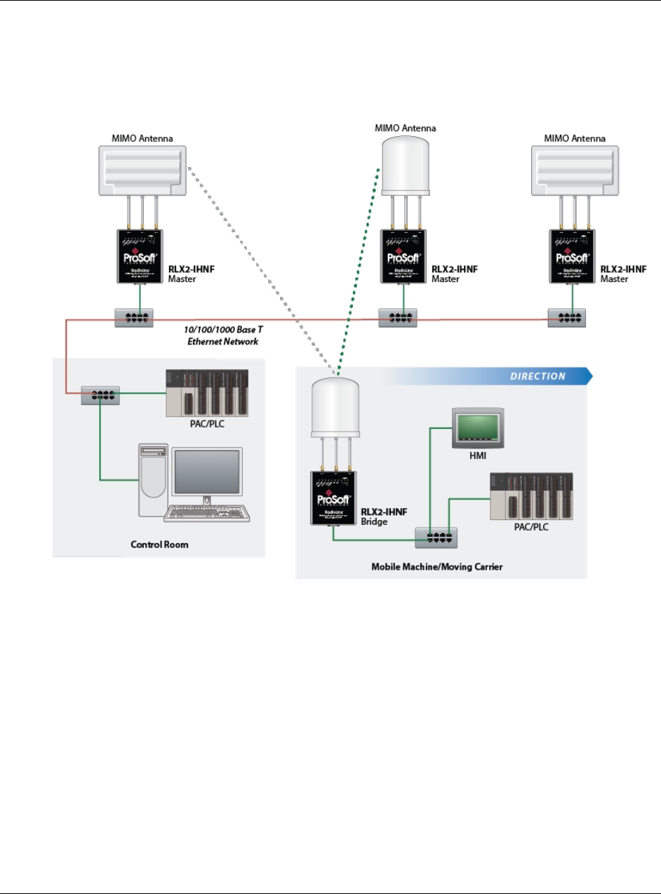
RLX2-IHx series ♦ 802.11a, b, g, n Appendix K - Application Examples
Industrial Hotspots User Manual
ProSoft Technology, Inc. Page 209 of 227
October 30, 2017
17 Appendix K - Application Examples
This chapter provides example applications using RLX2-IHx series radios.
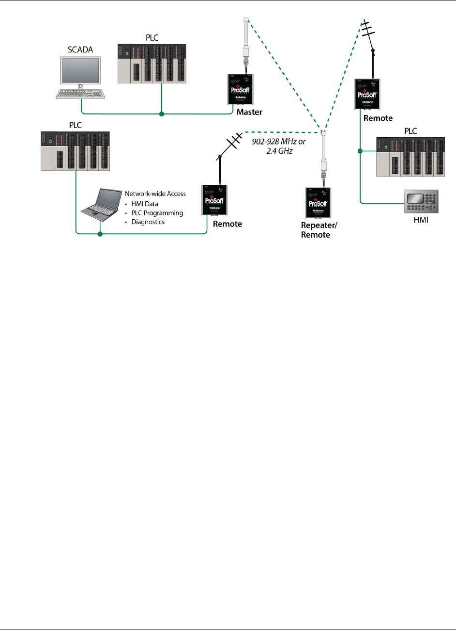
Appendix K - Application Examples RLX2-IHx series ♦ 802.11a, b, g, n
User Manual Industrial Hotspots
Page 210 of 227 ProSoft Technology, Inc.
October 30, 2017

RLX2-IHx series ♦ 802.11a, b, g, n Support, Service & Warranty
Industrial Hotspots User Manual
ProSoft Technology, Inc. Page 211 of 227
October 30, 2017
18 Support, Service & Warranty
In This Chapter
Contacting Technical Support ............................................................. 211
Warranty Information ........................................................................... 212
18.1 Contacting Technical Support
ProSoft Technology, Inc. is committed to providing the most efficient and
effective support possible. Before calling, please gather the following information
to assist in expediting this process:
1 Product Version Number
2 System architecture
3 Network details
If the issue is hardware related, we will also need information regarding:
1 Module configuration and associated ladder files, if any
2 Module operation and any unusual behavior
3 Configuration/Debug status information
4 LED patterns
5 Details about the serial, Ethernet or Fieldbus devices interfaced to the
module, if any.
Note: For technical support calls within the United States, ProSoft’s 24/7 after-hours phone support
is available for urgent plant-down issues. Detailed contact information for all our worldwide
locations is available on the following page.

Support, Service & Warranty RLX2-IHx series ♦ 802.11a, b, g, n
User Manual Industrial Hotspots
Page 212 of 227 ProSoft Technology, Inc.
October 30, 2017
Internet
Website: www.prosoft-technology.com
E-mail address: support@prosoft-technology.com
Asia Pacific
(location in Malaysia)
Tel: +603.7724.2080
E-mail: asiapc@prosoft-technology.com
Languages spoken include: Chinese, English
Asia Pacific
(location in China)
Tel: +86.21.5187.7337 x888
E-mail: asiapc@prosoft-technology.com
Languages spoken include: Chinese, English
Europe
(location in Toulouse,
France)
Tel: +33 (0) 5.34.36.87.20
E-mail: support.EMEA@prosoft-technology.com
Languages spoken include: French, English
Europe
(location in Dubai, UAE)
Tel: +971-4-214-6911
E-mail: mea@prosoft-technology.com
Languages spoken include: English, Hindi
North America
(location in California)
Tel: +1.661.716.5100
E-mail: support@prosoft-technology.com
Languages spoken include: English, Spanish
Latin America
(Oficina Regional)
Tel: +1-281-2989109
E-Mail: latinam@prosoft-technology.com
Languages spoken include: Spanish, English
Latin America
(location in Puebla, Mexico)
Tel: +52-222-3-99-6565
E-mail: soporte@prosoft-technology.com
Languages spoken include: Spanish
Brasil
(location in Sao Paulo)
Tel: +55-11-5083-3776
E-mail: brasil@prosoft-technology.com
Languages spoken include: Portuguese, English
18.2 Warranty Information
For complete details regarding ProSoft Technology’s TERMS & CONDITIONS
OF SALE, WARRANTY, SUPPORT, SERVICE AND RETURN MATERIAL
AUTHORIZATION INSTRUCTIONS, please see the documents at:
www.prosoft-technology/legal
Documentation is subject to change without notice.

RLX2-IHx series ♦ 802.11a, b, g, n Glossary of Terms
Industrial Hotspots User Manual
ProSoft Technology, Inc. Page 213 of 227
October 30, 2017
19 Glossary of Terms
Symbols & Numeric
802.11
A group of wireless specifications developed by the IEEE. It details a wireless
interface between devices to transport packet traffic.
802.11a
Operates in the 5 GHz frequency range with a maximum 54 Mbit/sec signaling
rate.
802.11b
Operates in the most commonly used 2.4 GHz Industrial, Scientific, and
Measurement (ISM) band. Provides signaling rates of up to 11 Mbit/sec using
CCK modulation.
802.11g
Similar to 802.11b but supports signaling rates of up to 54 Mbit/sec using OFDM
modulation. Operates in the heavily used 2.4 GHz ISM band.
802.11i
Sometimes called Wi-Fi Protected Access 2 (WPA 2). WPA 2 exclusively uses
the 128-bit and above Advanced Encryption Standard (AES), along with 802.1x
authentication and key management features.
802.11n
Uses higher modulation rates and packet aggregation to raise effective WLAN
throughput to more than 100 Mbit/sec.
A
Access Point
A generic term for an 802.11 radio that "attaches" other 802.11 (clients) to a
wired network. Some access points (APs) can also bridge to other APs.
Ad hoc Mode
Wireless network framework in which devices can communicate directly with one
another without using an accesspoint or a connection to a regular network.
RLX2-IHx series radio products do not support Ad hoc mode.
AES
Advanced Encryption Standard. New standard for encryption adopted by the U.S.
government for secure communications.
Amplifier
A device connected to an antenna that increases the signal strength and
amplifies weak incoming signals.

Glossary of Terms RLX2-IHx series ♦ 802.11a, b, g, n
User Manual Industrial Hotspots
Page 214 of 227 ProSoft Technology, Inc.
October 30, 2017
Antenna
A device connected to a wireless transceiver that concentrates transmitted and
received radio waves to increase signal strength and thus the effective range of a
wireless network.
ASCII
American Standard Code for Information Interchange. A communication mode in
which each eight-bit byte in a message contains one ASCII character code.
ASCII characters (or hexadecimal characters) are sometimes used as a key to
encrypt data and ensure its secure transmission.
Association
Process whereby two 802.11 radios establish communications with each other.
Requirements for communication include the same SSID (network names) and
encryption settings.
Authenticate
The process of confirming the identity of someone connecting to a network.
Authentication Server
A back-end database server that confirms the identity of a supplicant to an
authenticator in an 802.1x-authenticated network.
B
Band
Another term for spectrum used to indicate a particular set of frequencies.
Wireless networking protocols work in either the 2.4 GHz or the 5 GHz bands.
Bandwidth
(see Throughput)
Bridging Client, Radio Mode
A radio in Bridging Client mode can connect to any Access Point, and can
support one multiple Ethernet device but can only bridge IP-based traffic. See
also Repeater, Radio Mode.
C
CACT
CACT is an acronym for Channel Availability Check Time, a parameter used in
DFS channel selection. During DFS when a radio changes channels, it must
listen for the CACT on the new channel before beginning operations. For most
channels the CACT is 60 seconds.
Channel
One portion of the available radio spectrum that all devices on a wireless network
use to communicate. Changing the channel on the access point/router can help
reduce interference.
D

RLX2-IHx series ♦ 802.11a, b, g, n Glossary of Terms
Industrial Hotspots User Manual
ProSoft Technology, Inc. Page 215 of 227
October 30, 2017
dBi
Decibels referenced to an ideal isotropic radiator in free space; frequently used to
express antenna gain
dBm
Decibels referenced to one milliwatt (mW); an absolute unit used to measure
signal power (transmit) power output or received signal strength)
DCE
Data communications equipment. A modem, for example.
Decibel (dB)
A measure of the ratio between two signal levels; used to express gain (or loss)
in a system.
Default Gateway
The IP address of a network router where data is sent if the destination IP
address is outside the local subnet. The gateway is the device that routes the
traffic from the local area network to other networks such as the Internet.
Device-to-Device Network (Peer-to-Peer Network)
Two or more devices that connect using wireless network devices without the
use of a centralized wireless access point. Also known as a peer-to-peer
network.
DFS
DFS stands for Dynamic Frequency Selection, a requirement for operation on
certain frequencies in the 5 GHz band in many countries. When a radio operates
on a DFS frequency, it must sense the presence of radar and automatically
change to another channel if radar is detected.
DHCP
The dynamic host configuration protocol is an Internet protocol, similar to BootP,
for automating the configuration of computers that use TCP/IP. DHCP can be
used to automatically assign IP addresses, to deliver IP stack configuration
parameters, such as the subnet mask and default router, and to provide other
configuration information, such as the addresses for printer, time, and news
servers.
Direct Sequence Spread Spectrum
A modulation mechanism that spreads the signal for a wide band, allowing
reception even for overlapping data signals. 802.11b uses DSSS modulation.
Directional Antenna
Transmits and receives radio waves in a single direction.
Diversity Antenna
An antenna system that uses multiple antennas to reduce interference and
maximize reception and transmission quality.

Glossary of Terms RLX2-IHx series ♦ 802.11a, b, g, n
User Manual Industrial Hotspots
Page 216 of 227 ProSoft Technology, Inc.
October 30, 2017
DTE
Data Terminal Equipment, for example, a computer or terminal.
Dual Band
A device that is capable of operating in two frequency bands. On a wireless
network, dual-band devices are capable of operating in both the 2.4 GHz
(802.11b/g) and 5 GHz (802.11a) bands.
E
EAP
Extensible Authentication Protocol. A protocol that provides an authentication
framework for both wireless and wired Ethernet enterprise networks.
EIRP
Equivalent isotropically radiated power (EIRP) is the amount of power that would
have to be emitted by an isotropic antenna (that evenly distributes power in all
directions and is a theoretical construct) to produce the peak power density
observed in the direction of maximum antenna gain.
Encryption
Method of scrambling data so that only the intended viewers can decipher and
understand it.
F
Firmware
Firmware is the embedded software code that that runs in hardware containing a
CPU (similar to the BIOS in a personal computer). This is distinguished from the
IH Browser software that is installed on the Configuration PC.
Fresnel Zone
An elliptical area on either side of the straight line of sight that must also be clear
for a long-range wireless network to work.
Full-Duplex
A communications circuit or system designed to simultaneously transmit and
receive two different streams of data. Telephones are an example of a full-duplex
communication system. Both parties on a telephone conversation can talk and
listen at the same time. If both talk at the same time, their two signals are not
corrupted.
G
Gain, Antenna
The amount by which an antenna concentrates signal strength in a wireless
network.
Gateway
In wireless terms, a gateway is an access point with additional software
capabilities such as providing NAT and DHCP and access to a Wide Area
network (WAN), Internet or other main network.

RLX2-IHx series ♦ 802.11a, b, g, n Glossary of Terms
Industrial Hotspots User Manual
ProSoft Technology, Inc. Page 217 of 227
October 30, 2017
Guard Interval (GI)
An interval of time between data symbols during transmission. The guard interval
time for 802.11a/b/g systems is fixed at 800 microseconds. 802.11n devices can
also use a 400 microsecond guard interval, falling back to 800 microseconds if
excessive data corruption is detected.
H
Half-Duplex
A communications circuit or system designed to transmit and receive data, but
not both simultaneously. CB or walkie-talkie radios are an example of a half-
duplex communication system. Either parties on a radio conversation may talk or
listen; but both cannot talk at the same time without corrupting each other's
signal. If one operator is sending, the other must be receiving to have successful
communication.
Hz
Hertz. The international unit for measuring frequency equivalent to the older unit
of cycles per second. One megahertz (MHz) is one million hertz. One gigahertz
(GHz) is one billion hertz. The standard US electrical power frequency is 60 Hz.
802.11a devices operate in the 5 GHz band; 802.11b and g devices operate in
the 2.4 GHz band.
I
IEEE
Institute of Electrical and Electronics Engineers, Inc. IEEE is a professional
organization with members in over 175 countries and is an authority in technical
areas such as computer engineering and telecommunications. IEEE developed
the 802.11 specifications.
IP Address
A 32-bit identification number for each node on an Internet Protocol network.
These addresses are represented as four sets of 8-bit numbers (numbers from 0
to 255), separated by periods ("dots").
Networks using the TCP/IP protocol route messages based on the IP address of
the destination. Each number can be 0 to 255. For example, 192.168.0.100 could
be an IP address. Each node on the network must have a unique IP address.
K
Key
A set of information (often from 40 to as much as 256 bits in size) that is used as
a seed to an encryption algorithm to encrypt (scramble) data. Ideally, the key
must also be known by the receiver to decrypt the data.
L

Glossary of Terms RLX2-IHx series ♦ 802.11a, b, g, n
User Manual Industrial Hotspots
Page 218 of 227 ProSoft Technology, Inc.
October 30, 2017
LAN
Local Area Network. A system of connecting PCs and other devices within the
same physical proximity for sharing resources such as internet connections,
printers, files, and drives. When Wi-Fi is used to connect the devices, the system
is known as a wireless LAN or WLAN.
LED
Light-emitting diode.
Line of Sight (LoS)
A clear line from one antenna to another in a long-range wireless network.
M
MAC ID
Media Access Control address. Every device has its own MAC address which is
a unique identifier used to unambiguously identify the source and destination of
any packet on the network.
Mbps
Megabits per second, or a million bits per second. A measure of data rate.
Megahertz
A measure of electromagnetic wave frequency equal to one million hertz. Often
abbreviated as MHz and used to specify the radio frequency used by wireless
devices.
MIC
Message Integrity Check. One of the elements added to the TKIP standard. A
signature is added by each radio on each packet it transmits. The signature is
based on the data in the packet, a 64-bit value (key) and the MAC address of the
sender. The MIC allows the receiving radio to verify (check) that the data is not
forged or altered.
MIMO
Multiple Input Multiple Output refers to using multiple antennas in a Wi-Fi device
to improve performance and throughput. MIMO technology takes advantage of a
characteristic called multipath, which occurs when a radio transmission starts out
at Point A and the reflects off or passes through surfaces or objects before
arriving, via multiple paths, at Point B. MIMO technology uses multiple antennas
to collect and organize signals arriving via these paths.
Modbus
The Modbus protocol provides the internal standard that the MODICON®
controllers use for parsing messages. During communications on a Modbus
network, the protocol determines how each controller knows its device address,
recognizes a message addressed to it, determines the kind of action to be taken,
and extracts any data or other information contained in the message. If a reply is
required, the controller constructs the reply message and sends it using Modbus
protocol.

RLX2-IHx series ♦ 802.11a, b, g, n Glossary of Terms
Industrial Hotspots User Manual
ProSoft Technology, Inc. Page 219 of 227
October 30, 2017
Modem
MOdulator-DEModulator, a device that converts digital signals to analog signals
and vice-versa. Analog signals can be transmitted over communications links
such as telephone lines.
N
Network
A series of stations or nodes connected by some type of communication medium.
A network may consist of a single link or multiple links.
Node
An address or software location on the network.
Non-Occupancy Period
The time during which a radio cannot return to a frequency where radar was
detected. This time is typically 30 minutes. Typically a radio will not return to a
channel where radar was previously detected unless absolutely necessary.
Null Modem Cable
A specialty cross-communication cable with female connectors on each end used
for direct connection between DTE devices when no modems are present.
Commonly used as a quick and inexpensive way to transfer files between two
PCs without installing a dedicated network card in each PC.
P
Panel Antenna
An antenna type that radiates in only a specific direction. Panel antennas are
commonly used for point-to-point situations. Sometimes called Patch antennas.
Parabolic Antenna
An antenna type that radiates a very narrow beam in a specific direction.
Parabolic antennas offer the highest gain for long-range point-to-point situations.
Peer-to-Peer Network
Each radio in a Peer-to-Peer network has the ability to receive data from, and
transmit data to, any other radio in the network.
Point-to-Multipoint
A wireless network in which one device (the access point or Master Bridge)
serves multiple other devices associated to it.
Point-to-Point Network
A network consisting of a single Master radio and a single Remote radio.
Poll
A method of electronic communication.

Glossary of Terms RLX2-IHx series ♦ 802.11a, b, g, n
User Manual Industrial Hotspots
Page 220 of 227 ProSoft Technology, Inc.
October 30, 2017
Power Supply
A device that supplies electrical power to the I/O chassis containing the
processor, coprocessor, or other modules.
Protocol
The language or packaging of information that is transmitted between nodes on a
network.
Q
QoS
Quality of Service. Required to support wireless multimedia applications and
advanced traffic management. QoS enables Wi-Fi access points to prioritize
traffic and optimize the way shared network resources are allocated among
different applications.
R
Range
The distance covered by a wireless network radio device. Depending on the
environment and the type of antenna used, Wi-Fi signals can have a range of up
to a several miles.
Repeater
A Repeater is a device used to extend the range of a Wi-Fi signal. Placed at the
edge of signal reception, a repeater can receive and re-transmit the signal.
Repeater, Radio Mode
A RLX2-IHx series radio in Repeater mode can only connect to other ProSoft
radios, but can bridge any number of Ethernet network devices attached to it. It
also simultaneously functions as an access point, allowing other wireless devices
to associate to it. See also Client, Radio Mode.
RS-232
Recommended Standard 232; the standard for serial binary signals between
DTE and DCE devices.
S
Sector Antenna
An antenna type that radiates in only a specific direction. Multiple sector
antennas are commonly used in point-to-multipoint situations.
Signal Diversity
A process by which two antennas are used to send and receive, combining their
results for better effect.
Signal Loss
The amount of signal strength that’s lost in antenna cable, connectors, and free
space. Signal loss is measured in decibels (dB). Also referred to as gain loss.
Signal Strength
The strength of the radio waves received at a wireless device.

RLX2-IHx series ♦ 802.11a, b, g, n Glossary of Terms
Industrial Hotspots User Manual
ProSoft Technology, Inc. Page 221 of 227
October 30, 2017
Site Survey
A comprehensive facility study performed by network managers to ensure that
planned service levels will be met when a new wireless LAN or additional WLAN
segments to an existing network are deployed. Site surveys are usually
performed by a radio frequency engineer and used by systems integrators to
identify the optimum placement of access points to ensure that planned levels of
service are met. Site surveys are sometimes conducted following the deployment
to ensure that the WLAN is achieving the necessary level of coverage. Site
surveys can also be used to detect rogue access points.
Spectrum
A range of electromagnetic frequencies.
Spread Spectrum
A form of wireless communication in which a signal’s frequency is deliberately
varied. This increases bandwidth and lessens the chances of interruption or
interception of the transmitted signal.
SSID
Service Set Identifier is a sequence of characters unique to a specific network or
network segment that’s used by the network and all attached devices to identify
themselves and allow devices to connect to the correct network when one or
more than one independent network is operating in nearby areas.
Subnet Mask
A mask used to determine what subnet an IP address belongs to. An IP address
has two components: the network address, and the host (node or device)
address; for example the IP address 150.215.017.009. Assuming this is part of a
Class B network (with a subnet mask of 255.255.0.0), the first two numbers
(150.215) represent the Class B network address, and the second two numbers
(017.009) identify a particular host on this network.
T
TKIP
Temporal Key Integrity Protocol. A wireless security encryption mechanism in Wi-
Fi Protected Access (WPA).
U
UART
Universal Asynchronous Receiver/Transmitter
W
WDS
Wireless Distribution System. Enables access points to communicate with one
another in order to extend the range of a wireless networks. Used in 802.11g
based access points.

Glossary of Terms RLX2-IHx series ♦ 802.11a, b, g, n
User Manual Industrial Hotspots
Page 222 of 227 ProSoft Technology, Inc.
October 30, 2017
WEP
Wired-Equivalent Privacy protocol was specified in the original IEEE 802.11
standard to provide a WLAN with a minimal level of security and privacy
comparable to a typical wired LAN, using data encryption.
Wi-Fi
A certification mark managed by a trade group called the Wi-Fi Alliance. Wi-Fi
certification encompasses numerous standards including 802.11a, 802.11b,
802.11g, WPA, and more. Equipment must pass compatibility testing to receive
the Wi-Fi mark.
Wi-Fi CERTIFIED™
The certification standard designating IEEE 802.11-based wireless local area
network (WLAN) products that have passed interoperability testing requirements
developed and governed by the Wi-Fi alliance.
Wi-Fi Interoperability Certificate
A statement that a product has passed interoperability testing and will work with
other Wi-Fi CERTIFIED products.
Wi-Fi Protected Setup
Wi-Fi Protected Setup™ (previously called Wi-Fi Simple Config) is an optional
certification program developed by the Wi-Fi alliance designed to ease set up of
security enabled Wi-Fi networks in the home and small office environment. Wi-Fi
Protected Setup supports methods (pushing a button or entering a PIN into a
wizard-type application) that are familiar to most consumers to configure a
network and enable security.
Wireless Gateway
A term used to differentiate between an access point and a more-capable device
that can share an internet connection, serve DHCP, and bridge between wired
and wireless networks.
Wireless Network
A network of connected using a centralized wireless access point.
WLAN
Wireless Local Area Network. A type of local area network in which data is sent
and received via high-frequency radio waves rather than cables or wires.
WPA
Wi-Fi Protected Access is a data encryption specification for 802.11 wireless
networks that replaces the weaker WEP. It improves on WEP by using dynamic
keys, Extensible Authentication Protocol to secure network access, and an
encryption method called Temporal Key Integrity Protocol (TKIP) to secure data
transmissions.
WPA2
An enhanced version of WPA. It is the official 802.11i standard. It uses Advanced
Encryption Standard instead of TKIP. AES supports 128-bit, 192-bit, and 256-bit
encryption keys.

RLX2-IHx series ♦ 802.11a, b, g, n Glossary of Terms
Industrial Hotspots User Manual
ProSoft Technology, Inc. Page 223 of 227
October 30, 2017
Y
Yagi Antenna
An antenna type that radiates in only a specific direction. Yagi antennas are used
in point-to-point situations.

RLX2-IHx series ♦ 802.11a, b, g, n Glossary of Terms
Industrial Hotspots User Manual
ProSoft Technology, Inc. Page 224 of 227
October 30, 2017

RLX2-IHx series ♦ 802.11a, b, g, n Glossary of Terms
Industrial Hotspots User Manual
ProSoft Technology, Inc. Page 225 of 227
October 30, 2017
Index
2
2.4 GHz Band, Point-To-Multipoint • 195
2.4 GHz Band, Point-To-Point • 196
5
5 GHz Bands, Point-To-Multipoint • 196
5 GHz Bands, Point-To-Point • 197
A
About RLX2-IHx series Industrial Hotspot Products •
16
About This Manual • 15
Access Settings • 82
Active Antennas
RLX2-IHW • 85, 87
RLX-IHNF • 85, 87
Adding the Radio to RSLogix 5000 • 152
Advanced Wireless Settings • 84, 97
Agency Approvals & Certifications • 202, 203, 206, 207
Antenna Gain • 188
Antenna Location, Spacing, and Mounting • 194
Antenna Pattern • 187
Antenna Polarity • 188
Antenna Port Connections • 18, 34
Antenna Spacing Requirements for User Safety • 7
Antenna Types • 189
Antennas • 185
Appendix A - Adding a Radio to RSLogix 5000 • 151
Appendix B - Radio Hardware • 163
Appendix C - RLX2-IHx 5 GHz Radio DFS Support •
171
Appendix D - RLX2-IHx series Virtual LAN (VLAN)
Functionality • 115, 175
Appendix E - EtherNet/IP and Modbus TCP/IP Support
• 179
Appendix F - Master Channel-Frequency Table • 183
Appendix G - Antenna Configuration • 18, 65, 72, 139,
185
Appendix H - FCC Emission Regulations • 195
Appendix I - Compatibility with ProSoft RLXIB Series
Radios • 15, 199
Appendix J - Detailed Radio Specifications • 17, 201
Appendix K - Application Examples • 209
Apply Changes • 62
Approved Antenna Table • 192
Approved Antennas in Europe/CE • 192
Approved Antennas in Mexico • 193
Approved Antennas with Power Amp • 192, 193
Assigning a Temporary IP Address • 42, 47, 48, 49,
50, 54, 128, 129
Assigning an IP address • 46, 48, 50, 53, 82
B
Basic Wireless Settings • 71, 97
Before You Begin • 15
C
Cable Break Detection • 106
Cancelling Changes • 62
Certificate Management • 80
Changing IH Browser Columns in List View • 120
Changing Password Settings • 93
Checking the Ethernet Cable • 146
Collinear Array Antennas • 189
Configuration Help • 59
Configuring a Bridging Client Radio • 50, 73
Configuring a Client Radio • 25, 50, 53, 73
Configuring a Radio - Detailed Configuration • 44, 55,
57
Configuring a Radio - Getting Started • 43, 44, 55, 56,
129, 147
Configuring a Repeater Radio • 48, 73
Configuring Advanced Network Settings • 99
Configuring Advanced Settings • 83
Configuring Basic Settings • 70
Configuring Parent Link Settings • 89, 94, 120
Configuring Quality of Service (QoS) Settings • 113
Configuring Serial Settings • 107
Configuring VLAN Settings • 115
Connecting to the Radio Configuration Utility • 44, 46,
48, 50, 54, 57, 80, 121, 130, 132
Contacting Technical Support • 150, 211
Content Disclaimer • 2
Control Drawing • 186
D
Defining the Scan Parameters in the IH Browser • 118
Designer Functional Specifications • 30
Detecting 802.11 Access Points • 32, 138
DFS Radio Operations • 171, 173
Diagnostics and Troubleshooting • 145
E
Encryption Type • 75, 77
Enterprise Mode Settings • 75, 78
Ethernet Cable Configuration • 167, 168
Ethernet Cable Configuration (all other radios) • 169
Ethernet Cable Configuration (RLX2-IHNF-W) • 168
Ethernet Cable Specifications • 167
EtherNet/IP™ Server Support • 181
F
Factory Defaults • 62
Finding Missing Radios • 150
Freezing the Display in the IH Browser • 119
G
General Features • 17

Glossary of Terms RLX2-IHx series ♦ 802.11a, b, g, n
User Manual Industrial Hotspots
Page 226 of 227 ProSoft Technology, Inc.
October 30, 2017
Glossary of Terms • 213
H
Hiding the Toolbar and Status Bar in the IH Browser •
126
How to Contact Us • 2
I
IGMP Settings • 100
IH Browser System Requirements • 23
Important Safety Information • 3
Importing and Exporting IH Browser Data • 125
Importing the Add-On Instruction • 155
Improving Signal Quality • 31
Industrial Hotspot Bench Test Kit (RLX-IHBTK) • 22
Industry Canada Requirements: • 4
Installation Questions • 27
Installing IH Browser Software • 23, 24
Installing the ProSoft Wireless Designer • 25, 26
Installing the RadioLinx Industrial Hotspot Browser • 22
IP address, Assigning • 46, 48, 50, 53, 82
L
LED Display • 17, 146
List View Columns • 120, 121, 127
Location Services Settings • 90
M
MAC Filter • 75, 76
Making Power and Data Connections • 30, 33, 34
Max Data Rate • 85, 86
Modbus Memory Map Diagnostic Information • 180
Modbus TCP/IP Server Support • 179
N
Network Planning • 25, 33
P
Package Contents • 20, 56
Packet Delineation Settings • 110
Parabolic Reflector Antennas • 191
Parent Selection Method Settings • 95
Password, Changing • 93
Personality Module Settings • 56, 62, 91
Ping Options Dialog Box • 134
Pinging Devices on the Network • 133, 134
Planning the Physical Installation • 27
Port Settings • 112
Port/Radio-based VLAN Tagging with Managed
Switches • 177
Port/Radio-based VLAN Tagging without Managed
Switches • 178
Preparing the Configuration Environment • 34
Printing the View in the IH Browser • 125
Product Overview • 16
ProSoft Wireless Designer • 28
R
Radio Power Requirements (All other radios) • 165
Radio Power Requirements (RLX2-IHNF-W) • 163
Radio Power-Up • 41
Rapid Spanning Tree Functionality • 102, 103
Read-Only Fields • 59
Recommended Antennas • 6
Refreshing the Display in the IH Browser • 42, 48, 118,
119, 150
Remote IP Settings • 109
Repeater Parameters Settings • 96
Replacing an Existing Radio • 33, 55, 91
Resetting a RLX2-IHx series Radio • 33, 44, 58, 131,
148
Resetting All Other Radios • 149
Resetting IH Browser Columns • 120
Resetting the RLX2-IHNF-W and RLX2-IHNF-WC •
148
RLX2 Controller Tags • 159
RLX2.CONTROL • 159
RLX2.STATUS • 160
RLX2-IHA Detailed Specifications • 201
RLX2-IHA, -IHG, -IHNF, -IHW • 20
RLX2-IHG Detailed Specifications • 202
RLX2-IHNF, RLX2-IHA, RLX2-IHG, RLX2-IHW • 4
RLX2-IHNF, -W, -WC Detailed Specifications • 204
RLX2-IHNF-W • 4, 21
RLX2-IHNF-W Cables (sold separately) • 21
RLX2-IHNF-W Radio Connections • 35
RLX2-IHNF-WC • 5, 22
RLX2-IHNF-WC Radio Connections • 37
RLX2-IHW Detailed Specifications • 206
RLX2-IHW, IHNF, IHG, IHA Radio Connections • 34
RLX2-IHx series Approved Antennas • 189, 191
RLX2-IHx series Quick Setup • 33
Roam Control Settings • 88
S
Selecting a DFS 5 GHz Channel • 172
Serial Encapsulation Mode Setting • 108
Setting the Event Log Filter • 141, 142
Setting the Radio IP Address in the IH Browser • 42,
128
Setting Up a Master Radio • 46, 72
SNMP Agent • 105
Spanning Tree Protocol • 101
Start Here • 15
Starting the IH Browser • 24, 32, 41, 118, 130
STP Settings • 98, 101
Support, Service & Warranty • 211
Switching between List and Topology Views • 120,
121, 124
T
Temporary IP Address, Assigning • 42
Testing the Network Installation • 27, 30
Topology View Description • 120, 124
Transparent Support of VLAN Tags (802.1Q) • 176

RLX2-IHx series ♦ 802.11a, b, g, n Glossary of Terms
Industrial Hotspots User Manual
ProSoft Technology, Inc. Page 227 of 227
October 30, 2017
U
Unable to scan for AP's error message • 149
Updating the Radio Firmware • 63, 132
Using the IH Browser to Configure Radios • 30, 41
Using the IH Browser to Manage your Radios • 24, 32,
41, 117
V
Viewing a Radio's Configuration • 55
Viewing Additional Data in the IH Browser • 125, 130
Viewing Available Parents for a Radio • 64, 65, 138
Viewing Ethernet Nodes in the IH Browser • 137
Viewing Network Data in the IH Browser • 135
Viewing Parent Radios in the IH Browser • 143
Viewing Radio Status • 63
Viewing the Port Table in the IH Browser • 140
Viewing the Radio Address Table • 64, 66
Viewing the Radio Event Log in the IH Browser • 141
Viewing the Radio Port Status • 64, 67, 103
Viewing the Radio Properties • 121, 126
Viewing the Radios in the IH Browser • 41, 118
Viewing the Scan List in the IH Browser • 138, 144
Viewing Wireless Clients in the IH Browser • 136
W
Warranty Information • 212
WEP Key • 75, 77, 78
Whip Antennas • 189
Wireless Security Settings • 74, 76, 98
Y
Yagi Array Antenna • 190
Your Feedback Please • 2