ProSoft Technology OS2400 Spread Spectrum Transmitter MODULE User Manual E21 Users Manual 3
ProSoft Technology, Inc Spread Spectrum Transmitter MODULE E21 Users Manual 3
Contents
- 1. Exhibit 12
- 2. E13 NewUserManual
- 3. E21 Users Manual 3
E21 Users Manual 3

OS2400 Radio Module Exhibit 21: User Manual 3 FCC ID: OQ7OS2400
1
Table of Contents
Product Overview 3
Summary of Function and Use .....................................................................3
FCC Rules 4
FCC Compliance Statement.........................................................................4
Approved Antennas......................................................................................5
Max Antenna Gain / Output Power ...............................................................6
Getting Started 7
Setup Overview............................................................................................7
The Setup / Diagnostic Software ..................................................................8
Functional Conventions................................................................................9
Hardware Installation .................................................................................10
Cable Specifications ............................................................................10
Radio Power Requirements .................................................................10
The Serial Port.....................................................................................11
Viewing the Serial Port Settings.....................................................11
Setting the Serial Port....................................................................11
Serial Port Factory Defaults Illustrated...........................................12
Network Design 14
Radio Network Basics ................................................................................14
Radio Network Defined........................................................................14
Network_Channels ..............................................................................15
Network Types.....................................................................................15
Point-To-Point ...............................................................................15
Point-Multipoint..............................................................................16
Installation Planning...................................................................................18
Site Selection.......................................................................................18
Antenna Selection................................................................................19
Whip Antennas..............................................................................19
Antenna Types Illustrated ..............................................................21
Configuring the Network.............................................................................22
Define Network Name, Type, Channel .................................................22
Graphical Layout Screen......................................................................22
Adding Radios for Point Multipoint .......................................................23
Move Radios........................................................................................24
Rename Radios...................................................................................25
Graphically Define the RF Link.............................................................26
Delete a Radio.....................................................................................27
Save the Network’s Definition ..............................................................28
Configuring the Radios...............................................................................29
Configure the Radios ...........................................................................29
Save the Radio’s Configuration............................................................30
Physical Installation and Network Verification 31
Test the Installation Plan............................................................................31
Sources of Interference..............................................................................32
Modifying an Existing Network....................................................................33
Viewing (and Changing) a Radio’s Settings................................................34
Change a Network’s Channel.....................................................................35
Upgrade Software - Download Code ..........................................................36

OS2400 Radio Module Exhibit 21: User Manual 3 FCC ID: OQ7OS2400
2
Miscellaneous Options 37
Select Radio Color.....................................................................................37
Radio’s Address-an explanation.................................................................38
Print the Network’s Configuration ...............................................................39
Printer Settings ..........................................................................................39
Zoom View of Graphical Layout..................................................................40
Automatic Arranging of Network Icons........................................................43
Diagnostics - Troubleshooting 44
System Diagnostics, an Overview ..............................................................44
“Viewing” a Network’s Function ..................................................................44
Broken Links in Point-to-Point ....................................................................45
Broken Links in Point-Multipoint Network....................................................46
Query a Radio Directly...............................................................................47
Query a Radio Remotely............................................................................49
Radios do not communicate.......................................................................50
Automatic Serial Port Check.......................................................................51
Can’t Configure a Radio.............................................................................52
Contact the Manufacturer...........................................................................53
Reference Information 53
Help on Windows Help...............................................................................53
Serial Port Basics.......................................................................................53
Glossary ....................................................................................................54
On-Line Help Options.................................................................................54
OS2400 Radio Module Exhibit 21: User Manual 3 FCC ID: OQ7OS2400
3
Product Overview
Summary of Function and Use
The OS2400s radios have been designed to provide a wireless replacement for any
serial cable. Any two devices which could otherwise function together with a physical
serial cable between them can be incorporated into a wireless network and continue to
function as before.
Spread spectrum: These radios transmit using a technique known as “spread
spectrum, frequency hopping communications”. Using the spread spectrum technique a
narrow band signal is spread over a broader portion of the radio frequency band.
Frequency hopping: A radio which rapidly changes its operating frequency several
times per second following a pre-determined sequence of frequencies is defined as
“frequency hopping”. The receiving and transmitting radios are programmed to follow
the same frequency hopping sequence.
The OverAir design takes advantage of these characteristics which are inherent to the
spread spectrum technique:
??increased immunity to noise. Radios are designed to detect specific radio
frequencies. “Noise” is defined as an unwanted signal which has been
transmitted at the same frequency as the radio was designed to detect. There
are many man-made and natural sources of “noise”. Due to the spread spectrum
and frequency hopping techniques, the OS2400 operates more efficiently than a
radio which operates using conventional technology.
??multiple users can share the same frequency at the same time. As an example
of this, cellphone use is dependent upon spread spectrum transmission.
Under FCC rules, users of FCC certified spread spectrum products do not require their
own license from the FCC. The manufacturers of the products are required to apply for
and be granted an FCC license for the device. OverAir has been granted a license by
the FCC for the use of its OS2400 radios.

OS2400 Radio Module Exhibit 21: User Manual 3 FCC ID: OQ7OS2400
4
FCC Rules
FCC Compliance Statement
FCC RULES
The statements contained in this section “FCC RULES” are required. If the Locus, Inc.,
OverAir Solutions OS2400 radio is used as a component of any device, these
statements must be a component of that device’s product documentation.
FCC COMPLIANCE STATEMENT
The Locus, Inc., OverAir Solutions OS2400 device complies with Part 15 of the FCC
Rules. Operation is subject to the following two conditions:
??this device may not cause harmful interference, and
??this device must accept any interference received, including interference that
may cause undesired operation.
WARNING
Changes or modifications to this radio module not expressly approved by its
manufacturer, Locus, Inc., could void the user’s authority to operate the equipment.
NOTE:
The Locus, Inc., OverAir Solutions OS2400 module is labeled with an FCC ID number.
If this label is not visible when installed in an end device, the outside of the device MUST
also display a label referring to the enclosed OS2400. Wording on the label similar to
the following should be used:
“Transmitter Module FCC ID: OQ7OS2400”
OR
“This device contains Transmitter Module FCC ID: OQ7OS2400.”
NOTE:
OEM integrators using this module in their final products must provide appropriate
information for end-users to comply with FCC RF exposure requirements, as indicated in
this manual. Separate FCC approval is required for products operating with a separation
distance of less than 20 cm between the antenna and persons.

OS2400 Radio Module Exhibit 21: User Manual 3 FCC ID: OQ7OS2400
5
Approved Antennas
It is important to keep the radio’s antenna a safe distance from the user. In order to
meet the requirements of FCC part 2.1091 for radio frequency radiation exposure, this
module must be used in such a way as to guarantee at least 20 cm between the antenna
and the body, or more for high gain antennas. The FCC requires a minimum distance
from the user of 1mW cm2 squared power density” or 20cm, whichever is the greater
distance.
If a specific application requires a proximity of less than 20cm, the application must be
approved through the FCC for compliance to part 2.1093.
At the time of this printing, the antennas listed below were the only antennas approved
for use with the OS2400 Radio Modem. Use of other antennas must be approved
through Locus, Inc.
Antenna gain
(dBi)
Antenna Type Locus, Inc., approved antennas
(Manufacturer: mfg number) Minimum Distance from Body
(in)
2
¼ Wave Whip
¼ Wave Whip
¼ Wave Whip
¼ Wave Whip
NCC: N24ARSMA1
NCC: N2400SM8
NCC: NOV2400SMA
Centurion: WCR2400MRSP
20cm (7.9in)
5
Collinear Whip
Collinear Whip
NCC: N24HGASM1B
NCC: NOV24HEARSMA2B
20cm (7.9in)
6
Collinear Whip
MaxRad: MFB-24006
20cm (7.9in)
8
Collinear Whip
Patch
MaxRad: MFB-24008
MaxRad: MP24008FSMA
20cm (7.9in)
9
Collinear Whip
Mobile Mark: 0D9-2400
20cm (7.9in)
11
Patch
MaxRad: MP24011FSMA
20cm (7.9in)
The following high-gain antennas can only be used for point-to-point network applications:
13
Patch
MaxRad: MP24013FSMA
20cm (7.9in)
15
Yagi
Astron: P-2415
20cm (7.9in)
24
Parabolic Dish
Pacific Wireless: PMANT25
50cm (19.7in)

OS2400 Radio Module Exhibit 21: User Manual 3 FCC ID: OQ7OS2400
6
Max Antenna Gain / Output Power
NOTE:
All of the Locus, Inc., approved antennas meet the Point-to-Point antenna gain / output
power emissions requirement. The approved antennas with gains greater than 12dBm,
however, can only be used for point-to-point networks and may not be used for point-
multipoint networks. The calculations below illustrate this limitation.
The FCC transmitter power limit for this type of radio is 30 dBm (or 1 watt). In addition,
to ensure safety, the output of this module is limited to 250mW. To meet the FCC
requirements for emissions, the following restrictions on antenna gain must be adhered
to when establishing a radio network.
Point-to-Point network:
max power 250 mW / max antenna gain 24 dBi
??The transmitter power reference for a Point-to-Point network is 30dBm (1 watt) of
output power with an antenna gain of 6dBi. For each 1 dB decrease in output
power below this reference point, the antenna gain can increase by 3 dB.
??With the OS2400 radio module’s maximum output power of 250 mW, the
maximum allowable antenna gain is 24 dBi in a Point-to-Point application.
(30dBm - 24dBm) + (6dBi * 3) = 24dB
Point-Multipoint network:
max power 250 mW / max antenna gain 12 dBi
??The transmitter power reference for a Point-Multipoint network is 30 dBm (1 watt)
of output power with a maximum antenna gain of 6 dBi.
??For each 1 dB decrease of output power below this reference point, the antenna
gain can increase by 1 dB.
??The OS2400 radio module has a maximum output power of 250 mW or 24 dBm.
Therefore, the maximum allowable antenna gain at full output power is 12 dBi in
a Point-Multipoint application.
(30dBm -24dBm) + 6dBi = 12dBi

OS2400 Radio Module Exhibit 21: User Manual 3 FCC ID: OQ7OS2400
7
Getting Started
Setup Overview
A new radio network must be configured to function as required for the specific
application.
These are the main steps in the configuration of a new OS2400 radio network:
??Installing the setup/diagnostic software
??Identifying and setting the serial port
??Making the cable connections
??Network design
??Graphically defining the network
??Configuring the radios
??Physically installing the radios and antennas
??Verification of network installation

OS2400 Radio Module Exhibit 21: User Manual 3 FCC ID: OQ7OS2400
8
The Setup / Diagnostic Software
The OS2400 Setup Application provides a user interface for the configuration and
maintenance of a radio network, regardless of the intended application. It graphically
reflects the physical layout of the component radios.
The Setup Application provides a means to:
??configure new networks or radios:
??assign roles (Master or Remote) to the radios.
??define data paths
??set the radio’s operation parameters (baud rate, parity, etc.)
??edit existing networks or radios:
??add or delete Remote Radios (in point-multipoint networks only)
??re-assign roles to the radios.
??re-define operation parameters
??diagnose functioning of existing networks.
With a MASTER cabled to the PC, the status of each REMOTE can be displayed.
NOTE:
It is recommended that the OS2400 Setup Application be installed on only one computer
and that the network configuration be done from only that one computer.
When a network is designed, the configuration settings are stored in a database which is
internal to the OS2400 Setup Application. When networks are modified, the OS2400
Setup Application depends upon the retrieval of the network’s configuration history.
Network modification and maintenance is easier if the OS2400 Application Software is
installed on only one computer. All subsequent network-related configurations are done
using that one computer.
Through out these Help files, the computer into which the OS2400 Setup Application has
been installed will be referred to as the Configuration PC.
OS2400 Radio Module Exhibit 21: User Manual 3 FCC ID: OQ7OS2400
9
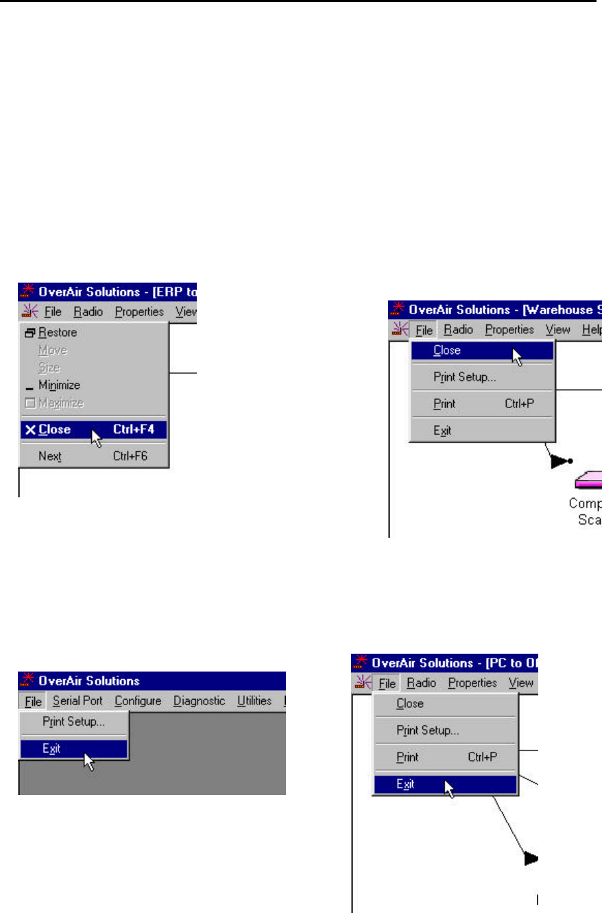
Functional Conventions
The OK, CANCEL, CLOSE and EXIT functions are available from many of the OS2400’s
Setup/Diagnostic Application screens. From any screen, these functions cause the
same action. They provide a consistent function throughout the Application.
??OK to confirm/enter any changes made and return to the Setup Software main
menu.
??CANCEL to discard any changes and return to the Setup Software main menu.
??CLOSE the current screen and return to the Main Screen:
??radio icon
??CLOSE
OR ??FILE
??CLOSE
??EXIT the application completely, select:
??FILE
??EXIT
From the Main Screen:
From either the Diagnostic or the
Configuration Screens:
OS2400 Radio Module Exhibit 21: User Manual 3 FCC ID: OQ7OS2400
10
Hardware Installation
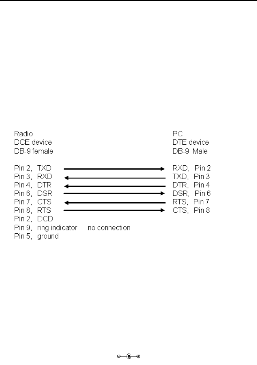
CABLE SPECIFICATIONS
The Radio is considered to be a DCE device.
The PC is considered to be a DTE device.
The following illustrates the wiring of the straight through serial cable which is used to
connect:
??the Configuring PC and each radio during its configuration.
??the Configuring PC and the Master radio during network operation.
RADIO POWER REQUIREMENTS
The standard radio includes an RS232 interface board with a switching power supply.
The switching power supply allows the operating input voltage to vary from 6 to 24VDC,
while maintaining an unvarying 6 Watts of input power.
The input connector is a standard power jack (Switchcraft; RAPC 722).
The wall cube connector is not included with the standard radio.
When purchasing the wall cube connector verify that its polarity is as indicated:
OS2400 Radio Module Exhibit 21: User Manual 3 FCC ID: OQ7OS2400
11
THE SERIAL PORT
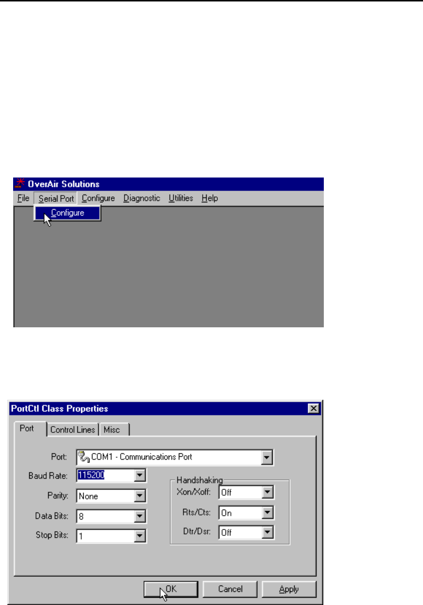
VIEWING THE SERIAL PORT SETTINGS
The serial port of the Configuration PC must be identified and its parameters set before
radio communication can begin.
To view the current settings, from the main menu of the OS2400 Setup Application
select:
??SERIAL PORT
??CONFIGURE
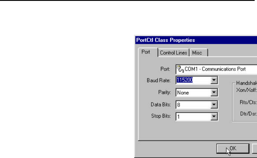
The displayed dialog box has three tabs. With the first of the tabbed dialog boxes,
PORT, the serial port settings are displayed. To understand how to customize these
settings see Setting the Serial Port.
SETTING THE SERIAL PORT
OS2400 Radio Module Exhibit 21: User Manual 3 FCC ID: OQ7OS2400
12
These are the factory-set serial port parameters for the Configuration PC.
Change these defaults with care.
??Baud rate: 115200 (default).
??Parity: None (default).
??Data Bits: 8 (default).
??Stop Bits: 1 (default).
??Handshaking:
It is recommended that the handshaking defaults
not be changed.
??Xon/Xoff OFF
??Rts/Cts ON
(Request to Send/Clear to Send)
??Dtr/Dsr OFF
(Data Terminal Ready/Data Set Ready)
??From the drop down list, select the COM port to be used. The term COM port
refers to the hardware connectors which allow the computer to COMmunicate
with other devices (like a printer or an OS2400 radio) through cables. Usually
the hardware connectors are located on the back of the computer.
The OS2400 Setup Application automatically determines and displays the serial ports.
NOTE:
The determination of the designation (name) of each COM port can be accomplished
several ways:
??look for a label at the connector on the back of the PC.
??consult the computer’s documentation.
??experiment, trial and error.
??check (and or adjust) the PC’s BIOS configuration.
In general, the factory set defaults will not have to be changed.
OK to accept the current settings.
For an illustration of the factory default serial port settings see Serial Port Factory
Default Settings.
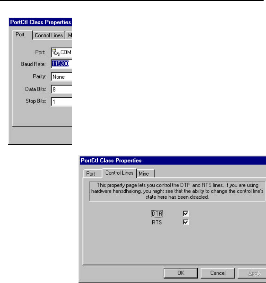
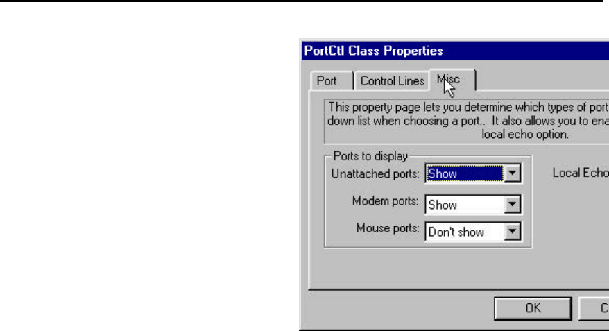
SERIAL PORT FACTORY DEFAULTS ILLUSTRATED
From any of the three associated dialog boxes, select:
??OK to confirm/enter any changes made and return to the Setup Software main
menu.
??CANCEL to discard any changes and return to the Setup Software main menu.
OS2400 Radio Module Exhibit 21: User Manual 3 FCC ID: OQ7OS2400
13
OS2400 Radio Module Exhibit 21: User Manual 3 FCC ID: OQ7OS2400
14
Network Design
Radio Network Basics
RADIO NETWORK DEFINED
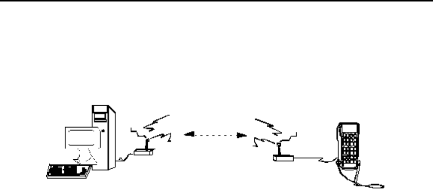
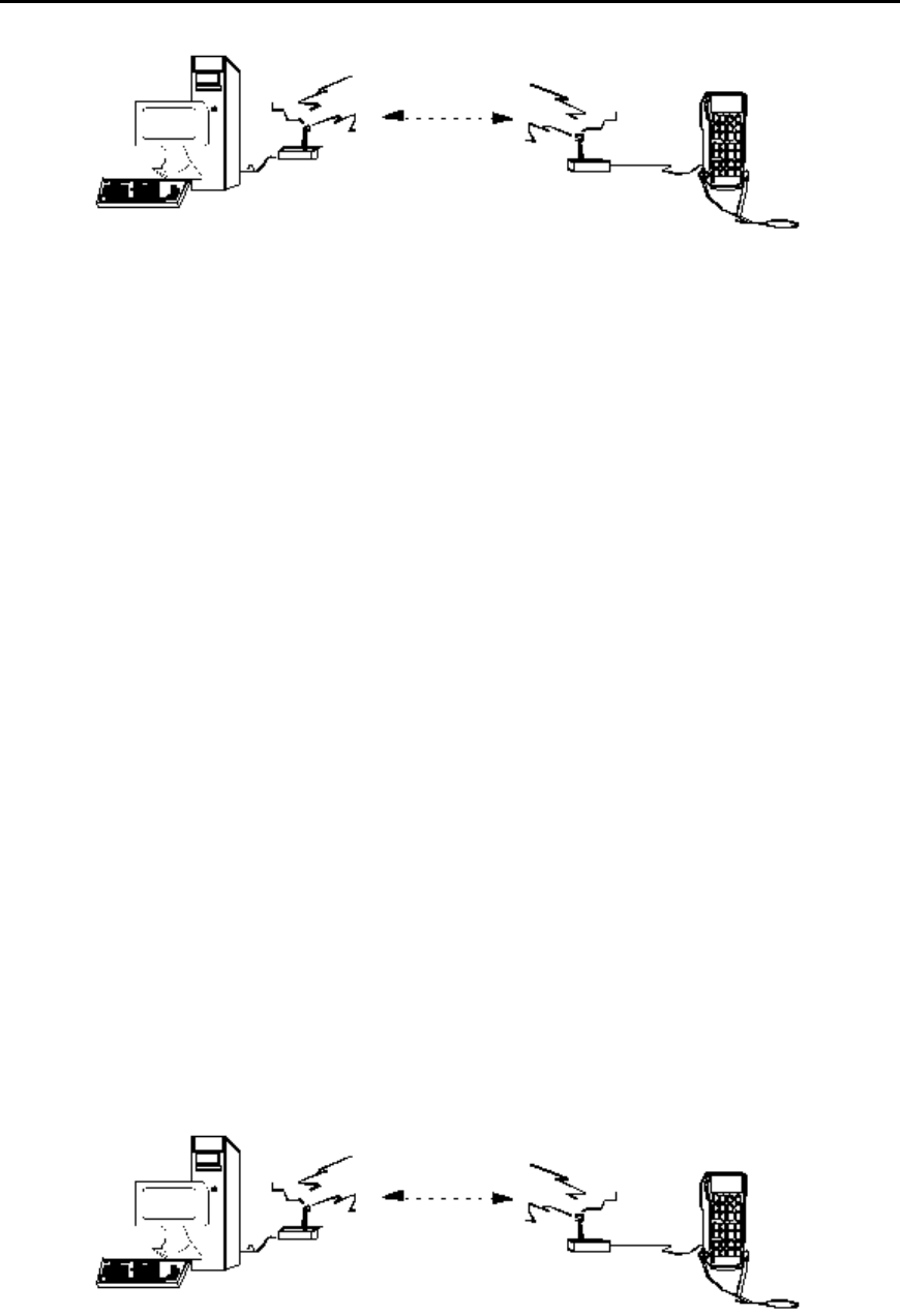
A radio network provides wireless replacements for serial cables. Any two devices
which could otherwise function together with a physical serial cable between them can
be incorporated into a wireless network and continue to function as before. The basic
network consists of a Master Radio cabled to one Device and a Remote Radio cabled to
another.
As examples, a Master Device - Remote Device pairs could be:
??a computer with a printer
??a computer with a scanner
??a scanner with a printer
??a Modbus controller and an industrial tool
A radio link can be used in any situation where a Master Device and its Remote Device
are located such that a serial cable connection between them is impractical or
impossible. The radios are designed to communicate up to 20 miles.
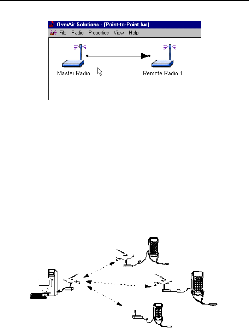
An example of a simple radio network is illustrated below. The Master Device is a
computer and its Remote Device is a hand held terminal.
OS2400 Radio Module Exhibit 21: User Manual 3 FCC ID: OQ7OS2400
15
NETWORK_CHANNELS
Network channel selection is used to allow the operation of several networks in the same
location. If the same network channel is selected for two networks which are close to
each other, the networks will interfere with each other, and may not communicate at all.
For network functionality these network channel requirements must be adhered to:
??The Master Radio and Remote Radio (or Radios) of each network must be
assigned to the same network channel.
??Networks in close proximity must be assigned to different network channels.
The Os2400 radio can support 32 channels. In this case a channel is a 500KHz wide
frequency range used for communication between two radios.
NETWORK TYPES
POINT-TO-POINT
There are two network types, point-to-point and point-to-multipoint.
In all networks there is only one Master Radio.
Point–to–Point networks are the simplest radio network. In a point-to-point network one
Master Radio is cabled to a Master Device and one Remote Radio is cabled to a
Remote Device.
Several point-to-point networks can operate at the same location, however each network
must use a different communication channel.
Each point-to-point network operates independently of each other, there can be no
intercommunication between the point-to-point networks.
OS2400 Radio Module Exhibit 21: User Manual 3 FCC ID: OQ7OS2400
16
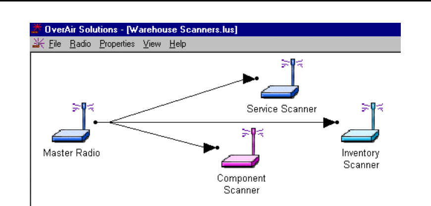
POINT-MULTIPOINT
In Point-Multipoint networks one Master Radio is in communication with at least two
Remote Radios. The Remotes can only communicate with their Master. Remotes
cannot communicate with each other directly, the data must be passed through the
Master. For this reason, a Point-Multipoint network will not work with an application
which requires peer to peer communication.
The OS2400 Point-Multipoint network can only be used with devices that are designed
to use the Modbus communication protocol. In a Modbus network each device has its
own Modbus address. In the network configuration process, each radio’s address must
be correlated with the Modbus address of the device cabled to it.
It may be that the data throughput rate is not as high as in a point-to-point network. In a
point-to-point network the data path is predefined. There are no choices. There is only
one destination. In a point-multipoint network the destination must be determined, the
address information must be resolved before the transmission can proceed.
OS2400 Radio Module Exhibit 21: User Manual 3 FCC ID: OQ7OS2400
17

OS2400 Radio Module Exhibit 21: User Manual 3 FCC ID: OQ7OS2400
18
Installation Planning
SITE SELECTION
A network’s performance can be impacted by attributes of the installation site. An
optimal installation provides for:
??protection from direct exposure to weather
??power source, both adequate and stable
??less than 256 radios per channel
??radios placed within 20 miles of each other
??line of sight between the Master and each Remote antennas, provides the most
reliable communication link
??portable Remote radio requirements, maintain a line of sight
??proximity of massive structures off of which radio signals can bounce, metal
walls
??sources of RF interference, electrical equipment (arc welding, switching power
supplies, etc.)
??antennas types
??cabling losses, signals lose power over cabled distance
Mounting the antenna on a tower or rooftop can provide a line-of-sight path if the site
contains obstructing terrain or structures. The line-of-sight consideration becomes more
important as the transmission path becomes longer. It is most important as the
transmission path approaches the limiting 20 mile specification.
Though radio frequency communication is reliable, sometimes its performance can be
impacted by intangibles. It is suggested that the network installation planning include
time and resources for performance testing and installation changes.
It is suggested that the installation plan be tested before the network is finally installed.
OS2400 Radio Module Exhibit 21: User Manual 3 FCC ID: OQ7OS2400
19
ANTENNA SELECTION
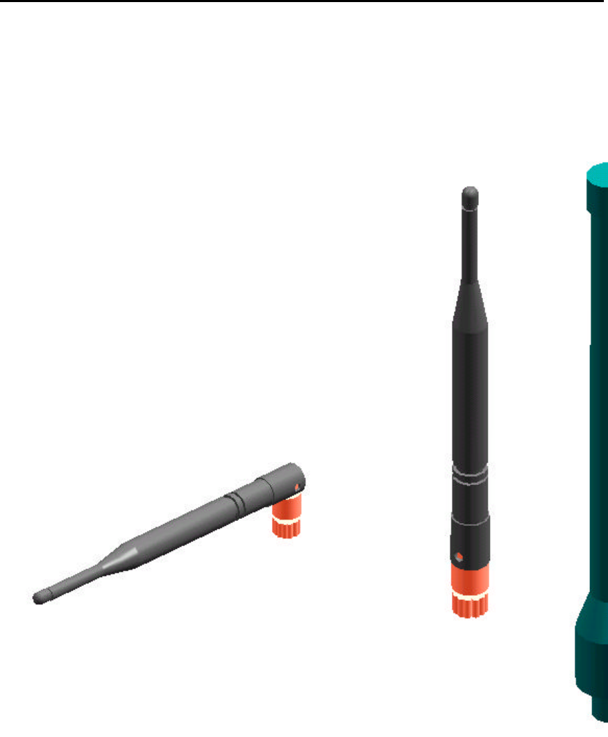
WHIP ANTENNAS
Only certain whip antennas have been approved for use with the OS2400 radio modem.
½? Straight Whip or ½? Articulating Whip (2dBi)
??Most commonly used antenna
??Length approximately 5 inches
??Likely to be connected to a remote radio (connected directly to
the radio enclosure)
??Does not require a ground plane
??Function of articulating, the same as unarticulating.
Articulating antenna bends at the connection.
¼? Whip Antenna (2dBi)
??Shorter than the ½? whip (2.5”)
??Requires a ground plane, mounted below the antenna and
over the top surface of the radio
??Needs to remain vertical (does not radiate well out the top of
antenna)
??Works well for belt mounted remote radios
We need some pictures here.
??
??
??
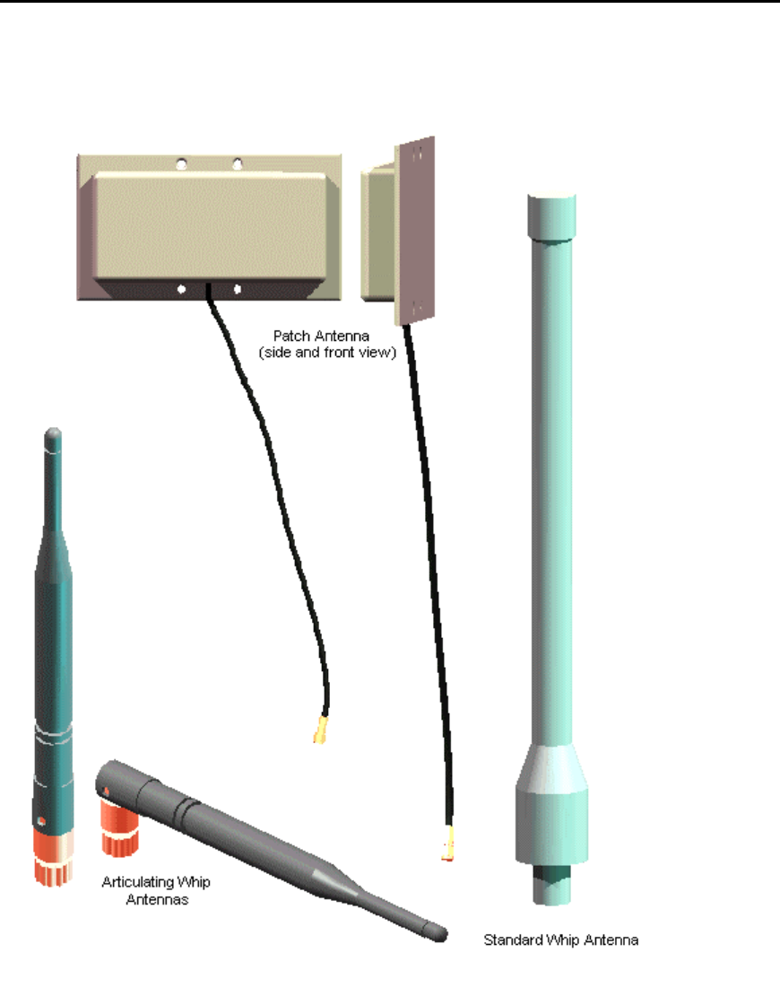
1. Disc Antenna (2dBi)
Low profile antenna (0.25” to 0.45” high)
??Requires a ground plane

OS2400 Radio Module Exhibit 21: User Manual 3 FCC ID: OQ7OS2400
20
??Same requirements as the ¼?whip antenna
??SubTypes (2 versions)
??Self contained w/ ground plane and connector
??Other versions are meant to be mounted to a circuit board which provided
connection and ground plane
2. 9dBi Gain Antenna (7-9dBi)
??Highest gain antenna allowable for point - multipoint networks
??Radiates uniformly around the antenna (Aismuth)
??Has limited elevation angle
??Used mostly as a master radio in the network
3. 15dBi Gain Antenna
??Restricted to point-point network only
??Used when long distances are needed
??Can be used by both the master and remote of the network
??SubTypes;
??Plate – are generally 2ft. square and several inches thick, they mount vertically
and the face of the plate points in the direction of radiation
??Yagi / Tube – range from 18” to 32” in length, and about 2” in diameter. They
mount horizontallyand point in the direction of radiation.
??Corner reflector / small radiating element with an L-shape reflector behind the
antenna.
??Parabolic / square reflector and shaped to form a pseudo-parabola with a
radiating element in the center
OS2400 Radio Module Exhibit 21: User Manual 3 FCC ID: OQ7OS2400
21
ANTENNA TYPES ILLUSTRATED
OS2400 Radio Module Exhibit 21: User Manual 3 FCC ID: OQ7OS2400
22
Configuring the Network
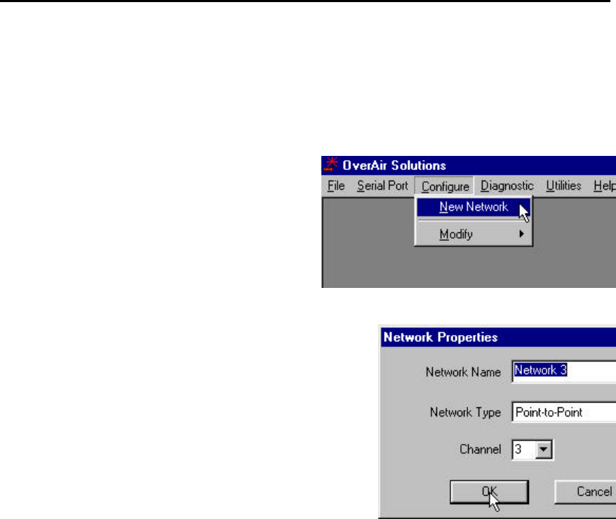
DEFINE NETWORK NAME, TYPE, CHANNEL
From the main menu of the OS2400 Setup Application select:
??CONFIGURE
??NEW NETWORK
A Network Properties dialog box is displayed. Using this dialog
box, the basic parameters of the new network is defined:
??Network Name: Use up to 20 alpha/numeric characters. The
OS2400 Setup Application will use this assigned name in all
subsequent references to this network. The network name
cannot easily be changed. It is recommended that the
user choose a descriptive name that all who may be
involved in the network’s maintenance will recognize.
??Network Type: From the drop down list select “Point-to-
Point” or “Point Multipoint”. See Network Types in this Help
system for an illustration of the available network types.
??Network Channel: Network channel selection is used to allow the operation of
up to 32 different networks in the same location. For network functionality these
channel requirements must be adhered to:
??The Master Radio and Remote Radio (or Radios) of each network must be assigned to the same channel.
??Networks in close proximity must be assigned to different channels. If the same channel is selected for two
networks that are close to each other, the networks will interfere with each other, and may not communicate
at all.
OK: to confirm/enter the selected network configuration and proceed to the graphical layout screen.
CANCEL: to close the Network Properties dialog box, discarding any changes made to the network properties.
GRAPHICAL LAYOUT SCREEN
OS2400 Radio Module Exhibit 21: User Manual 3 FCC ID: OQ7OS2400
23
When the settings of the Network Properties dialog box are accepted, a graphical
illustration of a basic two radio network with its communication path (RF link) is
displayed. This is the default layout screen for either a Point-to-Point or Point MultiPoint
Modbus network.
This is extent of the configuration of a Point-to-Point network.
For a Point-Multipoint design, additional Remote Radios are added with the Add Radio
function.
Note: Any radio can be moved.
Any radio can be renamed.
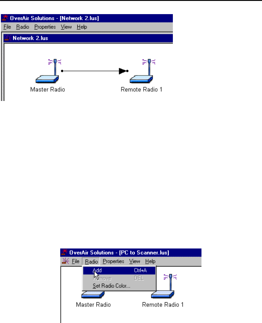
ADDING RADIOS FOR POINT MULTIPOINT
Select:
??RADIO
??ADD
An additional radio appears, supimposed on the Master.
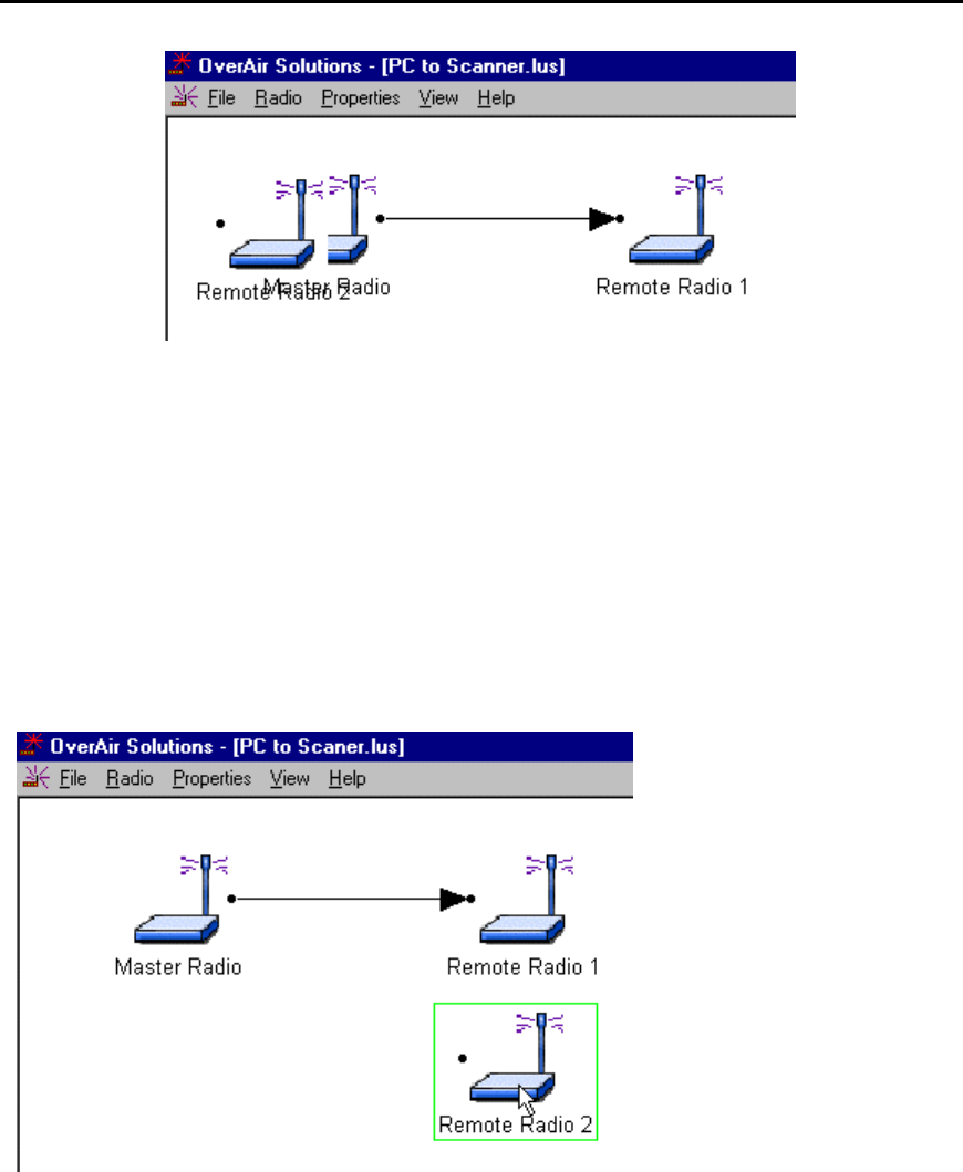
OS2400 Radio Module Exhibit 21: User Manual 3 FCC ID: OQ7OS2400
24
The additional Remote Radio must be moved.
Note:
The radios can be displayed in different colors. The color of a radio does not affect the
function of the network, however, there may be an application that can be more clearly
represented if the radios are represented with different colors in the graphical layout
screen. The color must be defined before the radio is added.
MOVE RADIOS
To move a radio, select it with the left mouse button.
Holding down the button, drag the radio to the location which best indicates the
topography of the network.
OS2400 Radio Module Exhibit 21: User Manual 3 FCC ID: OQ7OS2400
25
Communication connections will stretch and
shrink like “rubber bands”. Moving radios does
not alter the function of the network.
Note: In general, the network configuration as
displayed here is not the best topographical
model of a network’s layout. This layout was
devised for illustration only.
The default radio names can be changed.
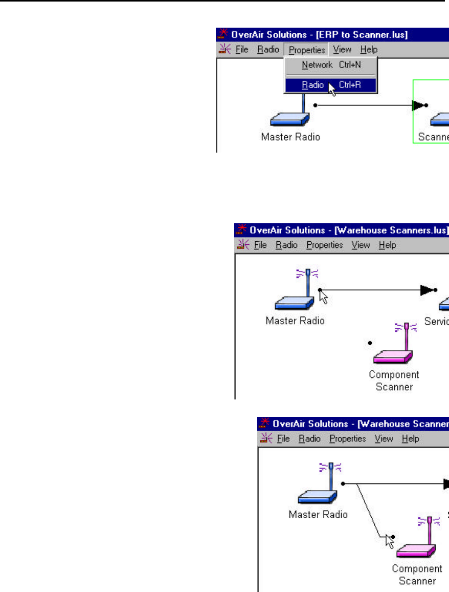
RENAME RADIOS
To rename an existing radio the Radio Configuration dialog box must be accessed.
Type the Radio’s new name into the “Radio Name” field.
This dialog box can be accessed in either of two
ways:
??Using the left mouse button, quickly double
click on the Radio’s icon.
??From the Graphical Layout Screen, select:
??PROPERTIES
??RADIO
OS2400 Radio Module Exhibit 21: User Manual 3 FCC ID: OQ7OS2400
26
GRAPHICALLY DEFINE THE RF LINK
Drag the cursor to the black dot to the right of the
Master.
Click down the left mouse button and hold it down.
With the left mouse button held down, drag the cursor to the
dot at the left of the Remote.
A line will appear between the Master and the Remote.
OS2400 Radio Module Exhibit 21: User Manual 3 FCC ID: OQ7OS2400
27
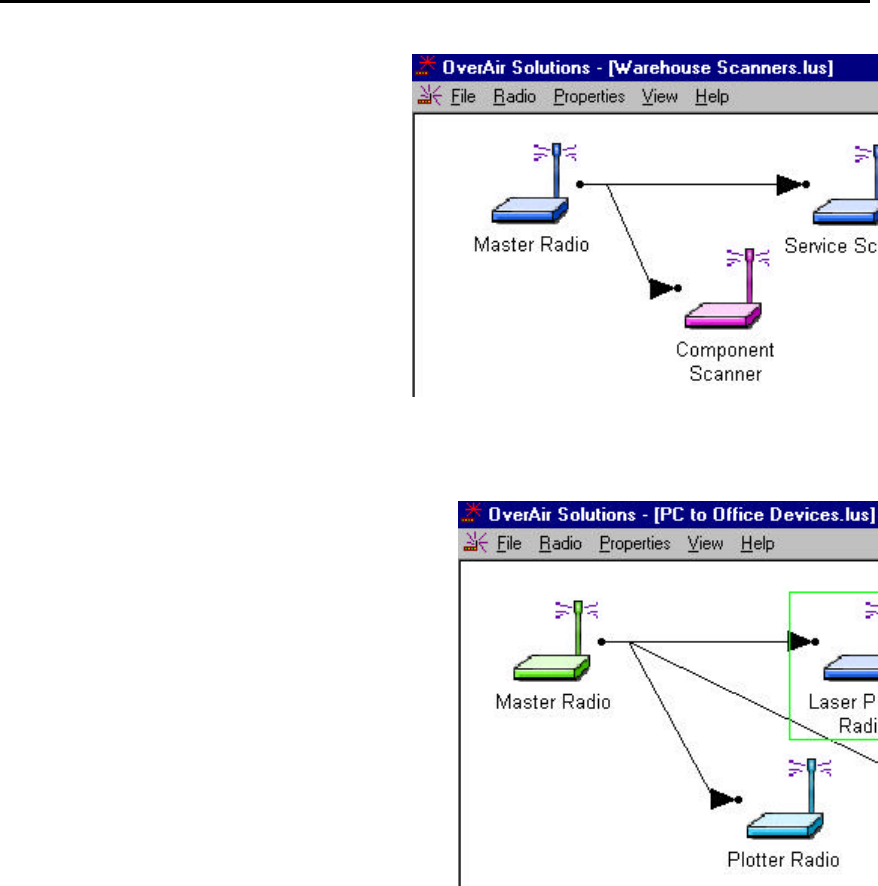
Release the mouse button go.
An arrow head will appear at the Remote.
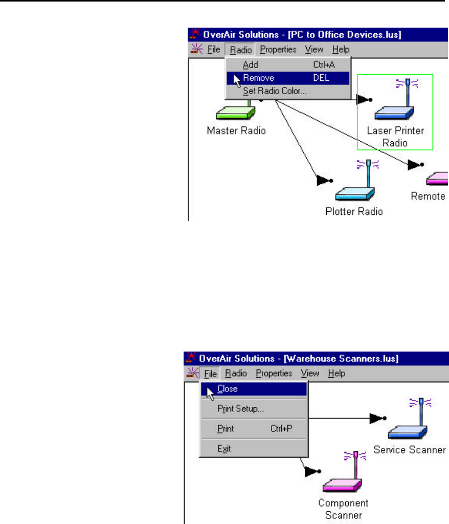
DELETE A RADIO
From the network’s Graphical Layout Screen select:
??(highlight) the radio to be deleted.
??RADIO
??REMOVE
OR
Select the keyboard’s DELete key
OS2400 Radio Module Exhibit 21: User Manual 3 FCC ID: OQ7OS2400
28
SAVE THE NETWORK’S DEFINITION
Save the Network’s definition in these two situations:
??if a new network has been defined
??if changes have been made to the network’s definition
From the Graphical Layout Screen
select:
??FILE
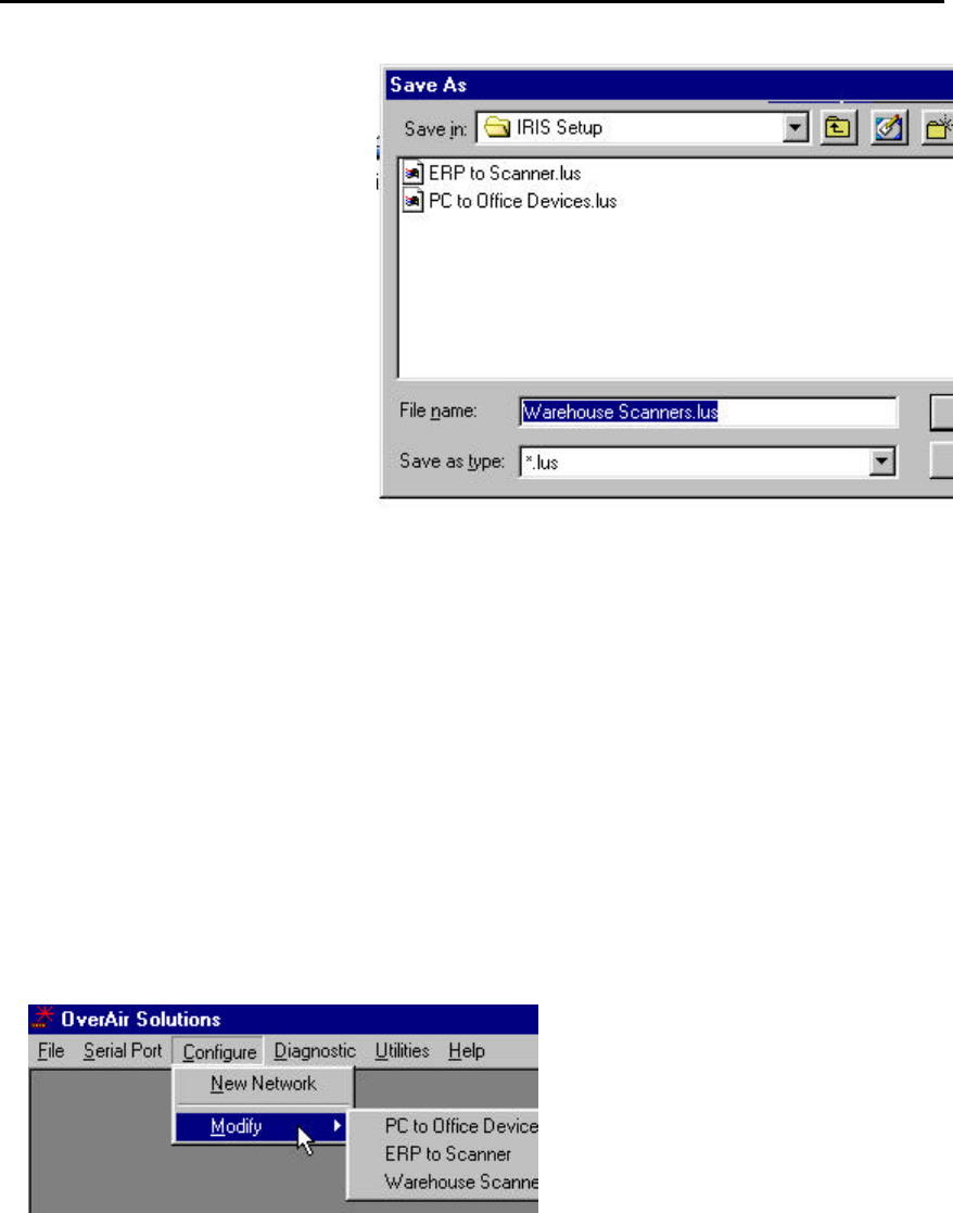
??CLOSE (or EXIT)
The standard Windows Save As dialog
box will be displayed. The network
name can be accepted as it is or it can
be edited here, but note:
THIS IS THE LAST TIME THAT THE
NETWORK’S NAME CAN BE
CHANGED.
OS2400 Radio Module Exhibit 21: User Manual 3 FCC ID: OQ7OS2400
29
Select:
??SAVE
NOTE: DO NOT change the default
directory. The OS2400
Setup/Diagnostic Application uses the
default directory to maintain network
related data.
The Network’s Definition can be printed.
Configuring the Radios
CONFIGURE THE RADIOS
Once the network is designed, the radios themselves must be configured.
Radios are configured one at a time using the Configuration PC (the one in which the
OS2400 Setup/Diagnostic Software has been installed).
Using the specified cable, connect the radio to the Configuration PC.
Note: Connect the radio to the PC’s COMmunication port as specified in the PC’s
serial port dialog box.
From the Main OS2400 Menu, select:
??CONFIGURE
??MODIFY
??the network by name
From the Graphical Layout Screen select:
??(highlight) the radio to be configured
??PROPERTIES
??RADIO
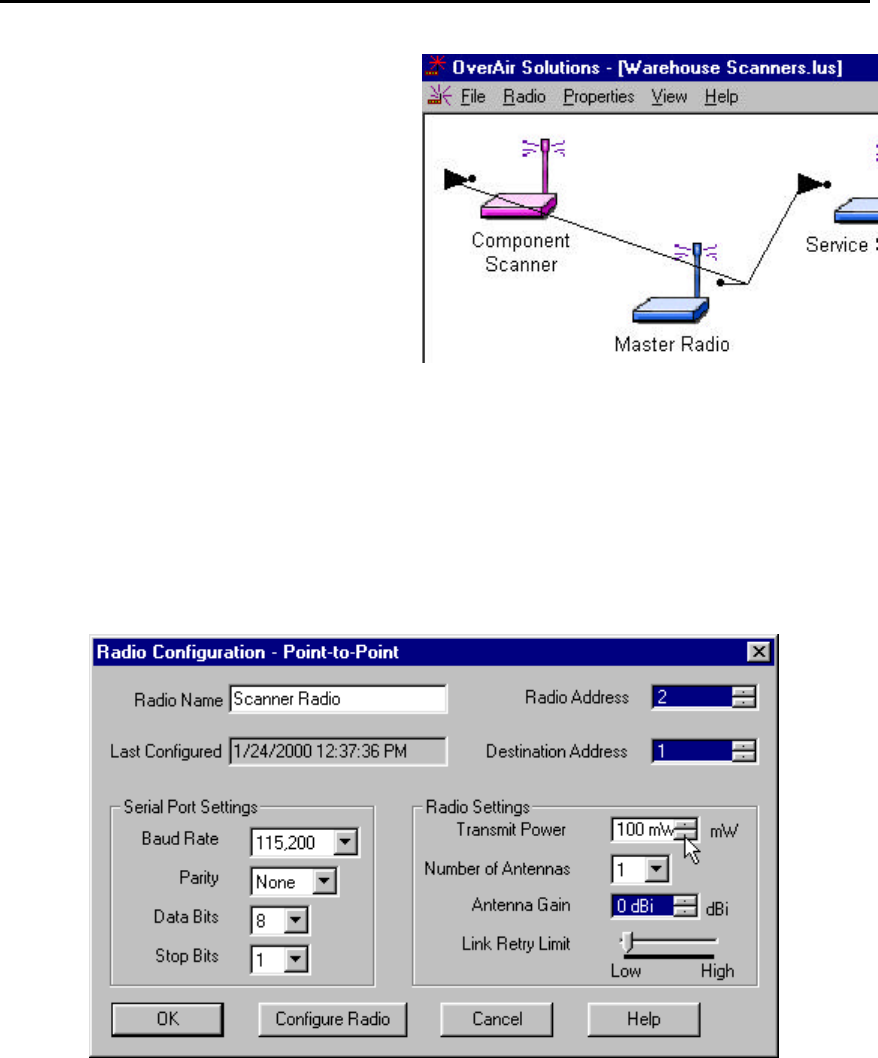
The Radio Configuration Dialog box is displayed:
OS2400 Radio Module Exhibit 21: User Manual 3 FCC ID: OQ7OS2400
30
Note: The Radio’s serial port settings (baudrate, parity, data bits and stop bits) must match those
of the Configuration PC’s.
Note: A good initial transmit power is 100mW. The power may need to be adjusted as part of the
installation optimization process.
To complete the radio’s configuration select:
??CONFIGURE RADIO
CONFIGURE RADIO button causes the download of radio parameters from the Configuration PC
to the radio. Once the configuration is complete save the configuration as prompted by the
OS2400 Setup / Diagnostics Application Software.
Note: Once a radio is configured, it is recommended that the radio be labeled with its role in the
network (Master or Remote), baud rate, channel, etc. Labeling can lessen confusion in the future.
If the radio’s configuration fails, consult the Diagnostics – Troubleshooting section.
SAVE THE RADIO’S CONFIGURATION
Once the radio has been configured, select:
??FILE
??CLOSE
This dialog box will appear. The name of the network
is incorporated into the filename. The *.lus is the
filename extension of each network’s database file.
The radio has just been configured. This information
must be added to the database file to keep the
database current.
Note: It is for this reason that all network design and
radio configuration be done using the Configuration
PC. When networks are modified, the OS2400 Setup
Application depends upon the retrieval of the
network’s configuration history.

OS2400 Radio Module Exhibit 21: User Manual 3 FCC ID: OQ7OS2400
31
Physical Installation and Network Verification
Test the Installation Plan
It is suggested that a proposed installation be tested before the installation is finalized.
Once the network has been configured and the radios have been configured:
??install the Master radio in the proposed permanent location
??cable the Configuration PC to the Master radio
??place the Remote radios in their proposed locations
??temporarily place each radio’s antenna near its proposed mounting location. The
temporary placement of the antenna can be by hand, however, then this testing
is at least a two person operation. The system’s diagnostics must be performed
from the Configuration PC.
From the Diagnostic screen of the Configuration PC determine each radio’s Signal
Quality.
To improve the signal quality of each Remote’s communication experiment with:
??increasing the height of the antenna’s placement
??use higher gain antennas
??increase the radio’s transmission power, cable the radio to the Configuration PC
and reconfigure it
??select a new location for the Remote radio and/or its antenna
??decrease the length of antenna cable
??determine and mitigate sources of “electrical” noise which may be interfering
with the OS2400 transmission

OS2400 Radio Module Exhibit 21: User Manual 3 FCC ID: OQ7OS2400
32
Sources of Interference
Radios are designed to detect specific radio frequencies. “Noise” is defined as an
unwanted signal which has been transmitted at the same frequency as the radio was
designed to detect. There are many man-made and natural sources of “noise”.
(lightning, power lines, switching power supplies, fluorescent lighting, microwave ovens,
...)
Due to the spread spectrum and frequency hopping techniques, the OS2400 operates
more efficiently than a radio which operates using conventional technology.
??Networks installed in rural areas will encounter less man-made noise than in
suburban or urban areas.
??If possible, use a directional (high gain) antenna at the Remote locations.
??Verify that each network operating in close proximity to each other has BEEN
ASSIGNED TO A DIFFERENT CHANNEL.
??A network’s output power can be changed:
??raise the power to “drown out” the competing noise
??lower a network’s output power if it is interfering with another network in the vicinity
OS2400 Radio Module Exhibit 21: User Manual 3 FCC ID: OQ7OS2400
33
Modifying an Existing Network
The radios within an existing network can be edited in several ways:
??new radios can be ADDed to a point-multipoint network.
??a radio’s settings can be changed (baud rate, output power, channel, etc)
??radios can be moved on the Graphical Layout Screen.
??radios can be renamed.
??radios can be deleted from a network.
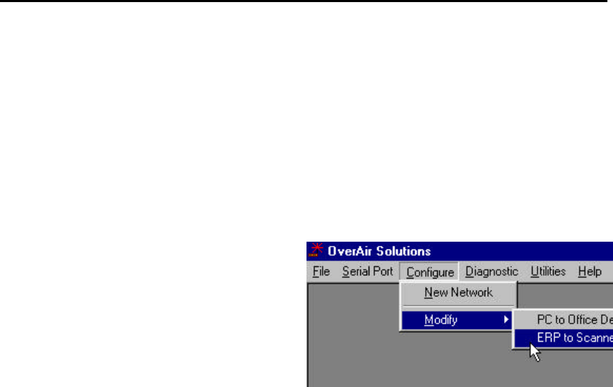
From the Main Menu select:
??CONFIGURE
??MODIFY
A drop down list will appear with the names of the
existing networks.
Note: When a network must be modified or its
function diagnosed, it becomes apparent that
assigning a good descriptive name when the
network is initially set up, is indicative of good
network design.
Only the channel of an existing network can be changed. Its type and name cannot be
changed.
OS2400 Radio Module Exhibit 21: User Manual 3 FCC ID: OQ7OS2400
34
Viewing (and Changing) a Radio’s Settings
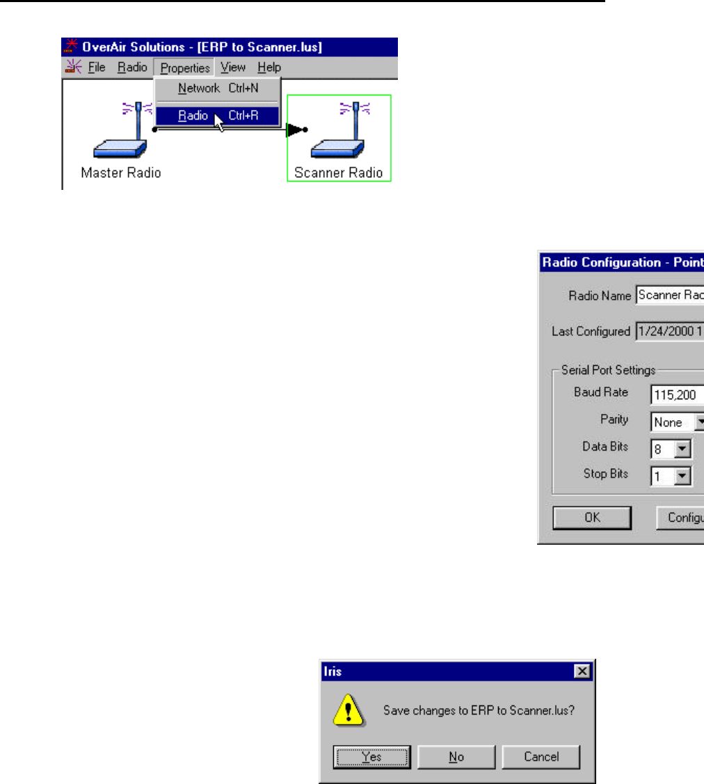
The settings of a radio can be viewed through the Radio Configuration Dialog box.
To view the settings of a particular radio select:
?? (highlight) the radio
??PROPERTIES
??RADIO
OR
??quickly double click on the radio’s icon with
the left mouse button
Radio Name: As it appears in this field, the
radio’s name will appear as a label under the
radio’s icon. The name can be any combination of
up to 100 alphanumeric characters and spaces.
Last Configured: The date and time reported
here indicates the last time that the configuration
parameters were modified and saved, or when the
radio was configured, configuration data was
downloaded to the radio.
Serial Port Settings: the serial port settings of the radio radio, (not the PC’s serial port).
Note: The settings of baud rate, parity, data bits (data word size) and stop bits must
match the settings of the device which will be cabled to the radio during normal network
operation.
Radio Address: each radio in the network is automatically assigned a unique address.
If a radio’s address is manually changed to an address already assigned to another
radio in the same network, neither radio will communicate over the network. It is
recommended that this addressing scheme not be changed by the user.
Note: In general, ACCEPT THE DEFAULTS.
The Radio Settings adjust the over the air performance of the radio network:
Transmit Power: This value should be set as low as possible and yet give a reliable
over the air connection to the receiving radio. A higher power setting than necessary
could increase the distance required between two networks operating on the same
channel.
Number of Antennas: This is sometimes referred to as “antenna diversity”. The
use of two antennas allows the radio to cancel out noise. “Noise” is defined as an
unwanted signal which has been transmitted at the same frequency as the radio was
designed to detect. There are many man-made and natural sources of “noise”.
Link Retry Limit: If there is an error in transmission, the transmitting radio will re-
send the data as many times as set with the Link Retry Limit slider switch. In normal
transmission, the receiving radio “acknowledges” that the data has been received
with no detected errors. If the transmitting radio does not get an acknowledgement,
it will re-transmit until the retry limit has been met. Moving the slider to the right will
OS2400 Radio Module Exhibit 21: User Manual 3 FCC ID: OQ7OS2400
35
allow more retries. In a Point Multipoint network a high retry limit may slow down
data transmission from another radio in the network.
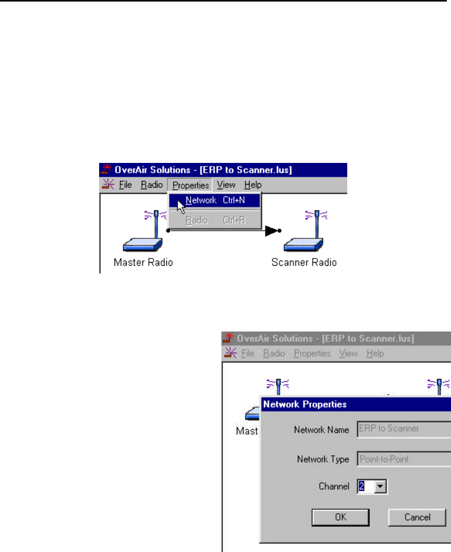
Change a Network’s Channel
From the Graphical Layout Screen of an existing network select:
??PROPERTIES
??NETWORK
Note that these fields are “greyed” out. These
network parameters cannot be changed:
??Network Name
??Network Type

OS2400 Radio Module Exhibit 21: User Manual 3 FCC ID: OQ7OS2400
36
Upgrade Software - Download Code
The download code utilities allow the user to upgrade the firmware of the radio. This is
done when updates to the features of the radio are implemented. To start a firmware
download, connect the radio to be upgraded to the COM port specified in the serial port
configuration. Select the Download Code option under the Utilities menu in the main
window.
Once this option is selected, the setup application program will automatically install the
firmware to the radio. This option is available only if the firmware setup and installation
have been executed on the setup application computer. If the firmware setup and
installation has not been performed, the Download code option in the Utilities menu will
be grayed out and cannot be executed.
The Download Code function is available under these circumstances. If either of these
conditions is missing the Download Code function will be unavailable (greyed out).
??the Download Code CD is in the Configuration PC’s CD drive
??at least one network has been configured
The Download Code function
OS2400 Radio Module Exhibit 21: User Manual 3 FCC ID: OQ7OS2400
37
Miscellaneous Options
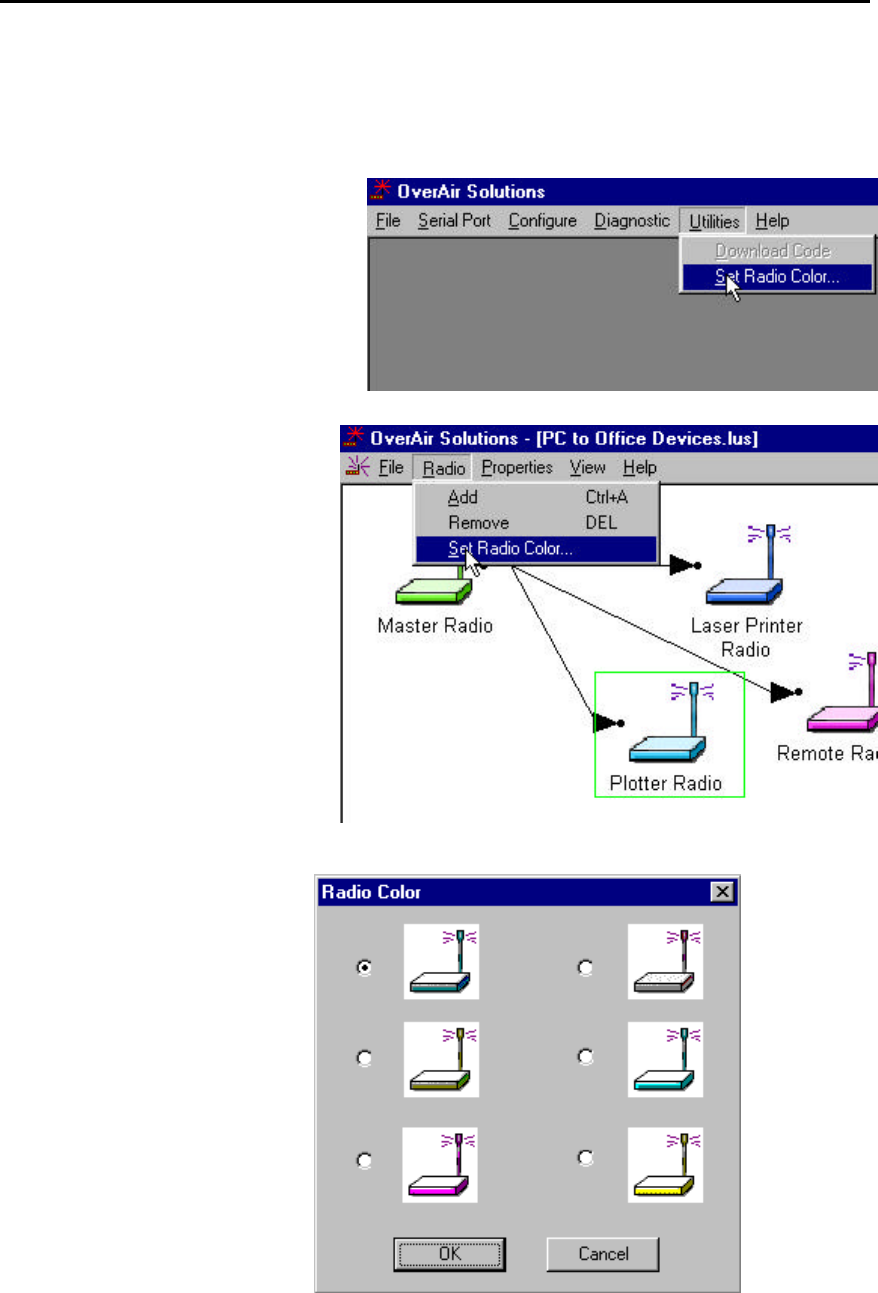
Select Radio Color
The radio color can be set for the whole
network from the Main Menu.
Select:
??UTILITY
??SET RADIO COLOR
The colors of individual radios can be
set at the time that a radio is added to
a Point-MultiPoint network.
Select:
??RADIO
??SET RADIO COLOR
The SET RADIO COLOR function
causes this selection box to
appear.
OS2400 Radio Module Exhibit 21: User Manual 3 FCC ID: OQ7OS2400
38
Radio’s Address-an explanation
Note: It is suggested that the automatically set radio addresses not be changed. This is
an explanation to soothe the curious.
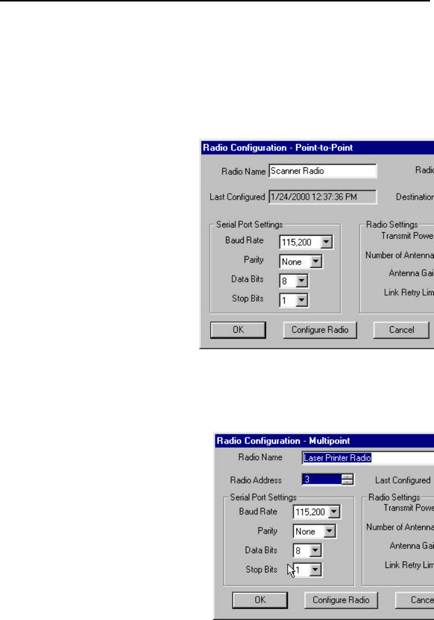
This Dialog box reflects the settings of a radio which is the Remote of a Point-to-Point
network.
In a Point-to-Point network this dialog box
reports both a Radio address and a
Destination address. The Destination Address
is the address of the radio to which the
selected radio will transmit all data.
By default:
??Master is assigned to address 1
??Remote is assigned to address 2
For the Master and Remote the Source and
Destination addresses are the inverse of each
other:
Master Remote
Address 1 2
Destination 2 1
If the addresses are to be manually changed,
this inverse relationship must be maintained.
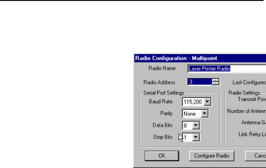
This is the Radio Configuration Dialog box of a radio which is a component of a Point-
Multipoint network.
In a Point-Multipoint network, all Remote radios
communicate with the Master and the Master
communicates with all Remotes. The point-
multipoint configuration dialog does not have a
Destination Address field.
OS2400 Radio Module Exhibit 21: User Manual 3 FCC ID: OQ7OS2400
39
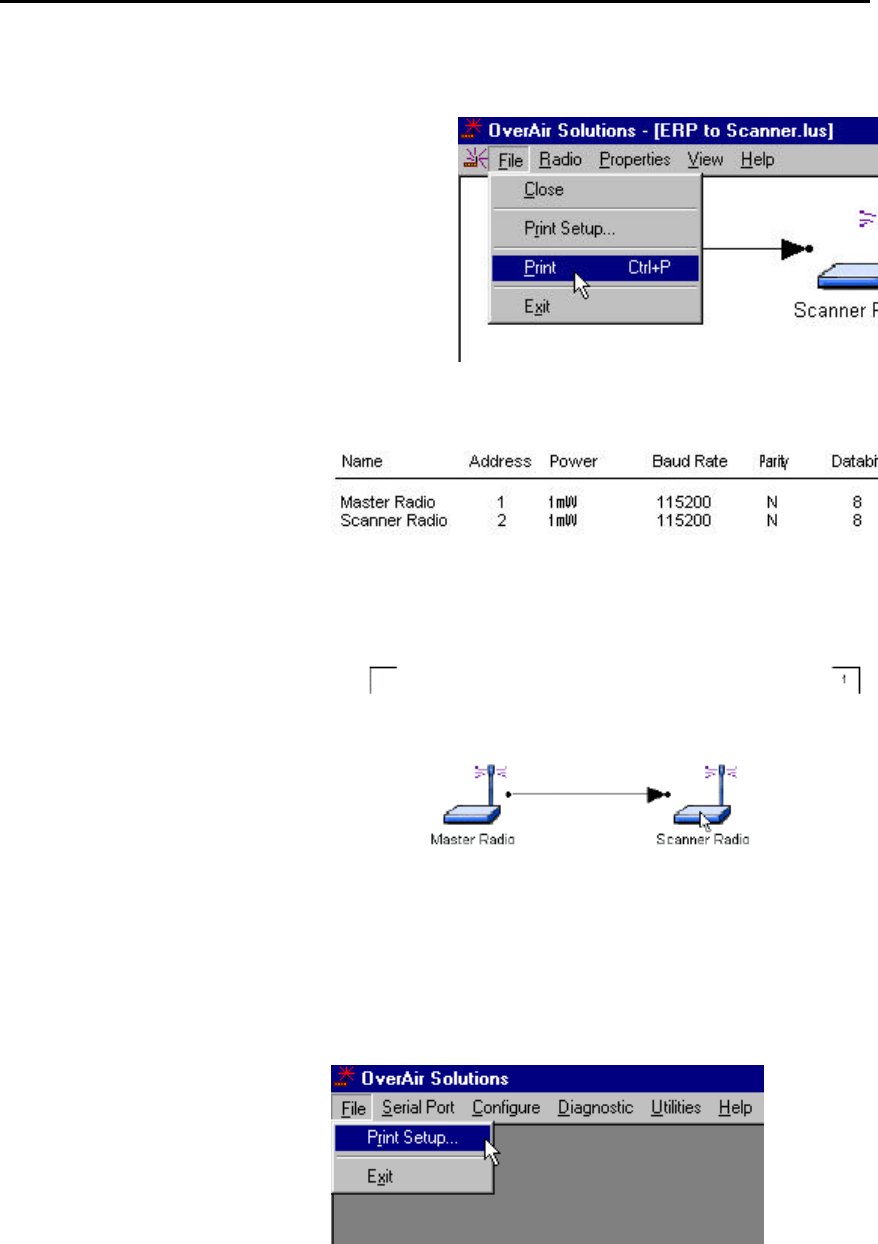
Print the Network’s Configuration
Two different network configuration reports can be
printed. One is from the Configure screen and the
other is from the Diagnostics screen.
From the Configuration screen:
This function generates a list of
network parameters which have
been stored in the OS2400’s
internal database. This list
becomes important for
troubleshooting.
From the Diagnostic screen:
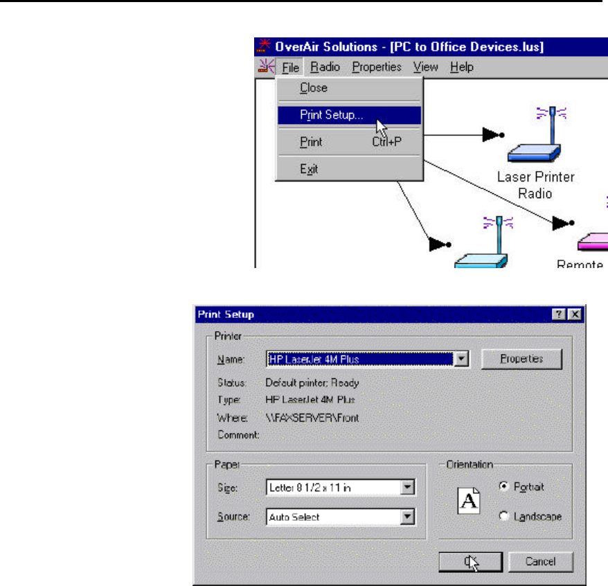
Printer Settings
For setup of the printer the PRINT
SETUP function can be accessed
from:
??the Main screen:
OS2400 Radio Module Exhibit 21: User Manual 3 FCC ID: OQ7OS2400
40
??the Configuration or Diagnostic
screen:
A standard printer set-up
dialog box is displayed.
Zoom View of Graphical Layout
In some cases it may be easier to manipulate the configuration of a network if the
graphical display of the network is either smaller or larger than the default display. The
ZOOM feature is useful for networks with a large number of radios.
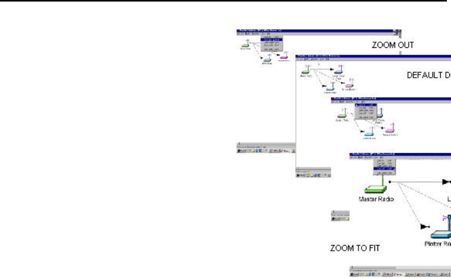
OS2400 Radio Module Exhibit 21: User Manual 3 FCC ID: OQ7OS2400
41
??ZOOM OUT: causes the display to “zoom
farther away”. The radios look smaller, more
overall space is displayed.
??ZOOM IN: causes the display to “zoom closer”
to the user. The radios look larger, less overall
space is displayed
??ZOOM TO FIT: causes the displayed network to
take up all of the screen, causes all of the
network to take up one screen.
OS2400 Radio Module Exhibit 21: User Manual 3 FCC ID: OQ7OS2400
42
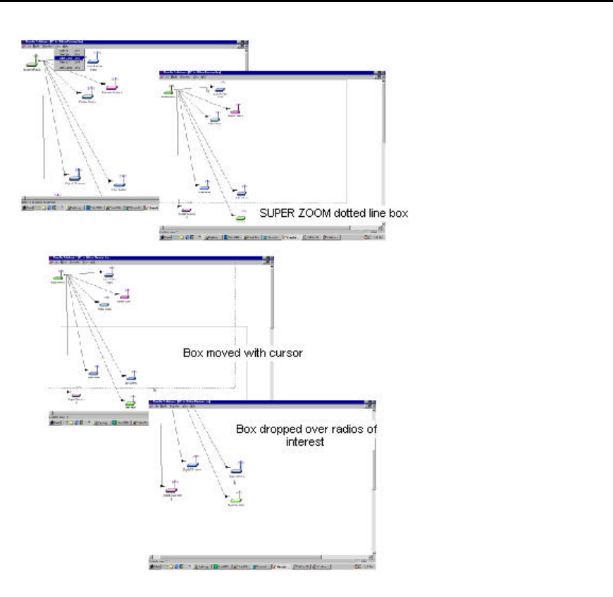
??
SUPER ZOOM: is used when the network covers more
space than one default screen.
When SUPER ZOOM is selected the whole network is displaye
with a dotted line box surrounding the space occupied by the
default display.
When the cursor is moved from the area of the default display
the dotted line box becomes a solid line box and moves,
following the placement of the cursor.
Once the box has
been placed over the section of network to be
viewed more closely, select the left mouse button. The box is
“dropped” and the selected section of the network is “
zoomed
in” to the display.
OS2400 Radio Module Exhibit 21: User Manual 3 FCC ID: OQ7OS2400
43
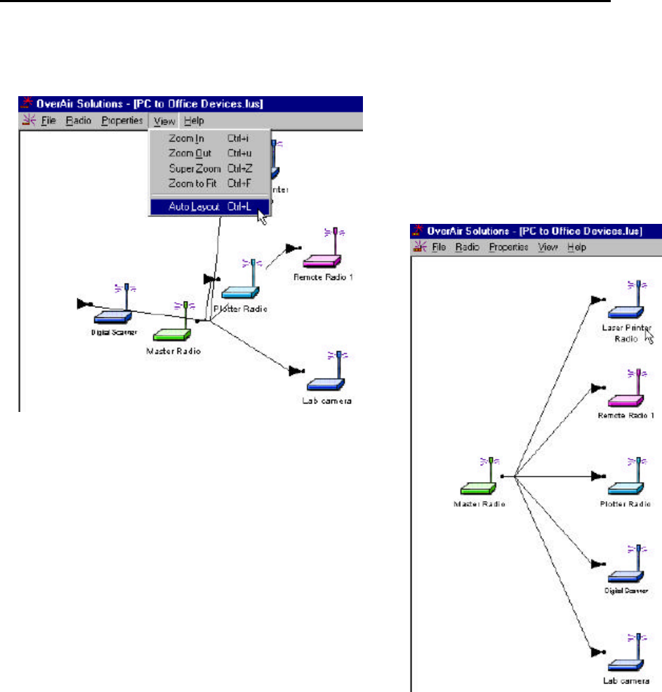
Automatic Arranging of Network Icons
If for some reason, someone has defined a
graphical network rat’s nest, the AUTO LAYOUT
function can be used to automatically redraw the
network in a hierarchical structure based on the
connections between the master radio and the
remote radios. This structure is also based on the
order on which the radios were added in to the
network in the diagnostic window.
OS2400 Radio Module Exhibit 21: User Manual 3 FCC ID: OQ7OS2400
44
Diagnostics - Troubleshooting
System Diagnostics, an Overview
Using the DIAGNOSTICS function :
??a graphical representation of the overall function of a network can be viewed
??an individual radio can be queried, and its operating parameters displayed
The information obtained from the diagnostics function can be used to:
??optimized network function
??determine the source of failed communication
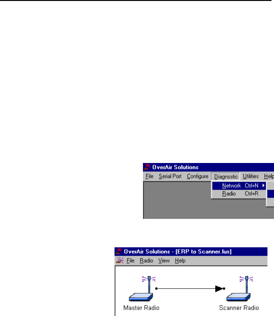
“Viewing” a Network’s Function
To view a graphical representation of a network’s
communication links, a Radio must be cabled to the
Configuration PC’s selected COM port.
From the Main OS2400 menu select:
??DIAGNOSTIC
??NETWORK
??select the network by name from the displayed
list of configured networks
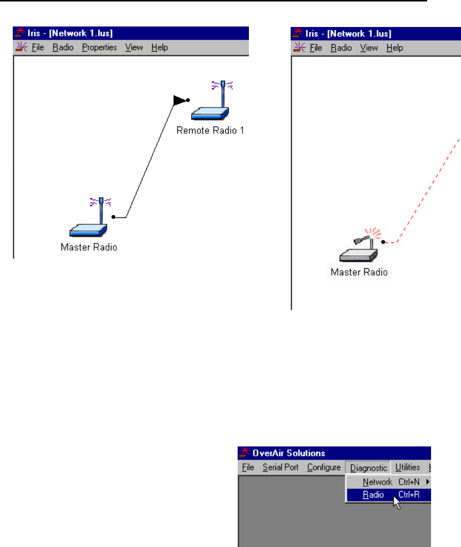
This is the OS2400’s graphical
representation of a Point-to-Point
network with intact communication links.
The RF link line is represented with a
solid black line.
OS2400 Radio Module Exhibit 21: User Manual 3 FCC ID: OQ7OS2400
45
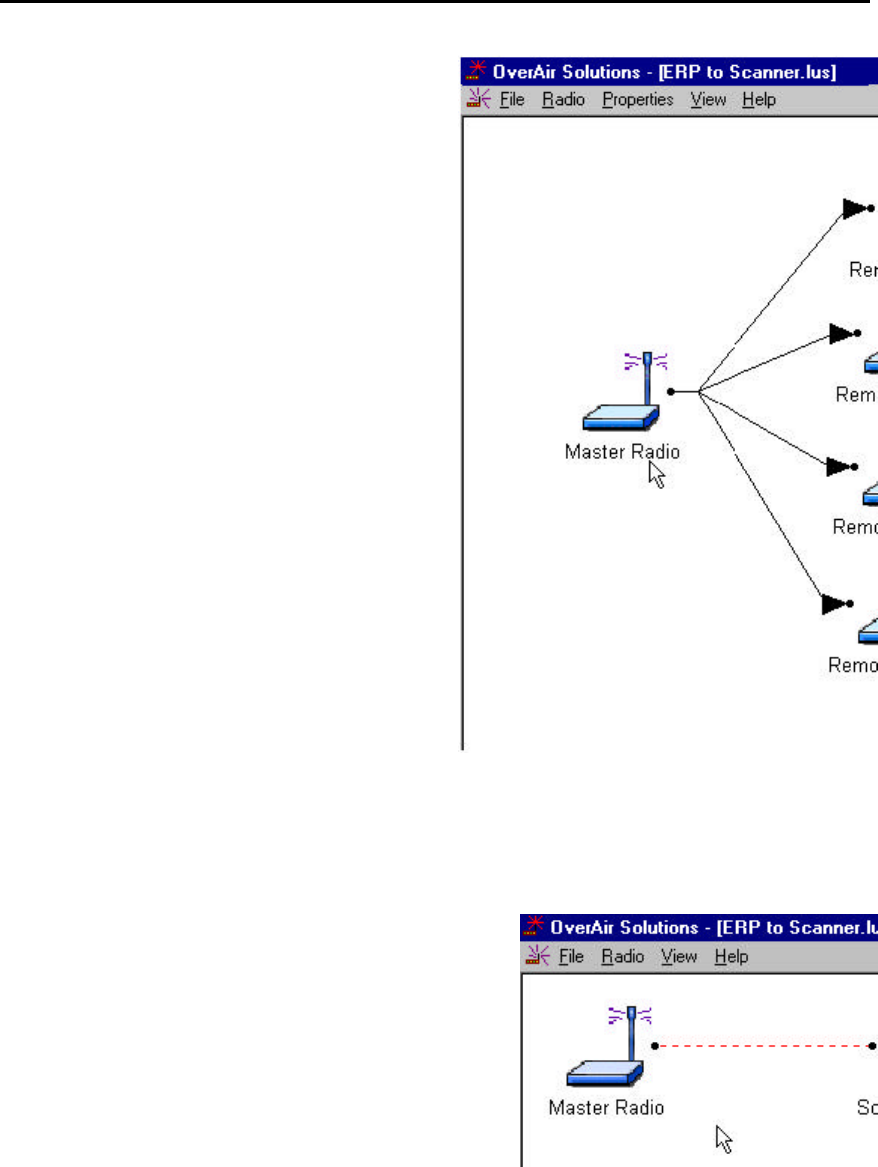
This Point-Multipoint network is functional. All RF
links are represented with solid black lines.
Broken Links in Point-to-Point
Either the Master or a Remote can be cabled to the
Configuration PC for network diagnosis.
In a Point-to-Point application, the displayed representation of
a failed communication link is not dependent upon which radio
is cabled to the PC.
In this example, the communication link has been broken. The
PC can communicate with the radio to which it is cabled. The
cabled radio cannot communicate with the remotely placed
radio.
OS2400 Radio Module Exhibit 21: User Manual 3 FCC ID: OQ7OS2400
46
This error message is displayed if the
Configuration PC cannot communicate with
the radio cabled to the PC.
There are several sources of error that should be considered.
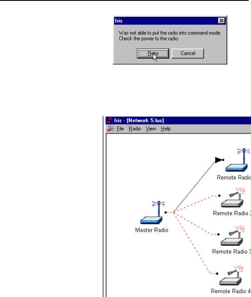
Broken Links in Point-Multipoint Network
Either the Master or a Remote can be
cabled to the Configuration PC for
network diagnosis. In a Point-
Multipoint application, the displayed
representation of a failed
communication link is dependent upon
which radio is cabled to the PC.
If the COM port is cabled to:
??the Master radio, all radios in the
network will be displayed.
If the COM port is cabled to:
??a functional Remote, only the representations of the Remote
radio and the Master radio will be displayed. In this example,
the only operational link is between the Master and Remote
Radio 1. The Remote radio cannot poll other Remote radios in
the network for diagnostic information. Remotes can only
communicate with its Master.
If the COM port is cabled to:
??a NONfunctional Remote, only the
representations of the Remote radio
and the Master radio will be displayed.
The link between the Master and
remote 1 is not operational, however,
the Remote is able to communicate with
the PC.
OS2400 Radio Module Exhibit 21: User Manual 3 FCC ID: OQ7OS2400
47
There are several sources of error that should be considered.
Query a Radio Directly
A radio can be queried so that it reports its settings to the Configuration PC.
This can be done either directly through a cable or remotely through communications
with the Master cabled to the Configuration PC. Check the serial port settings to
determine which COM port is configured for the OS2400 system, if necessary.
To directly query a radio, it is cabled to the Configuration
PC.
From the Main screen select:
??DIAGNOSTIC
??RADIO
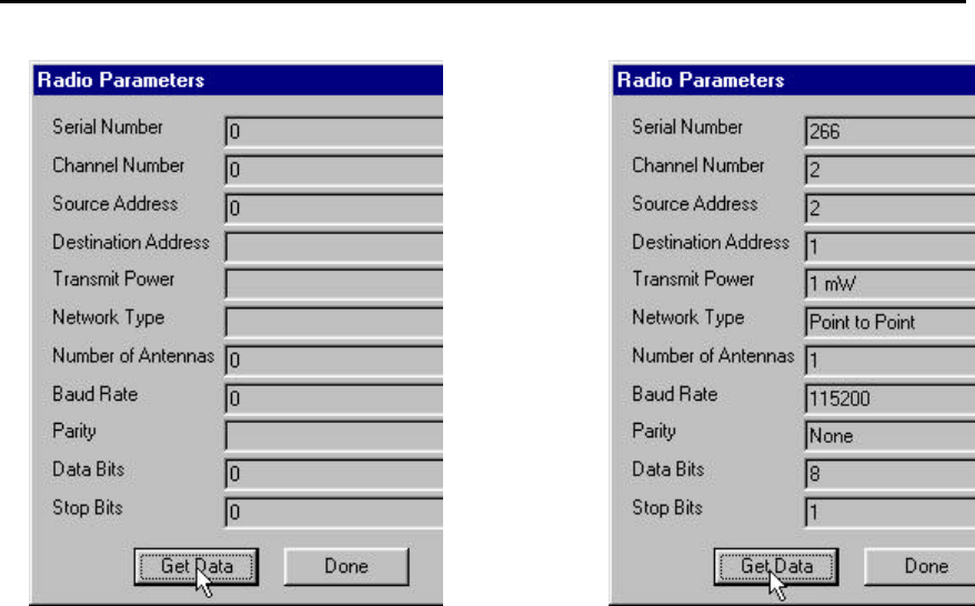
This dialog box will appear. No radio data is
reported until the GET DATA function is
actuated.
This is an example of the settings a radio
will report.
OS2400 Radio Module Exhibit 21: User Manual 3 FCC ID: OQ7OS2400
48
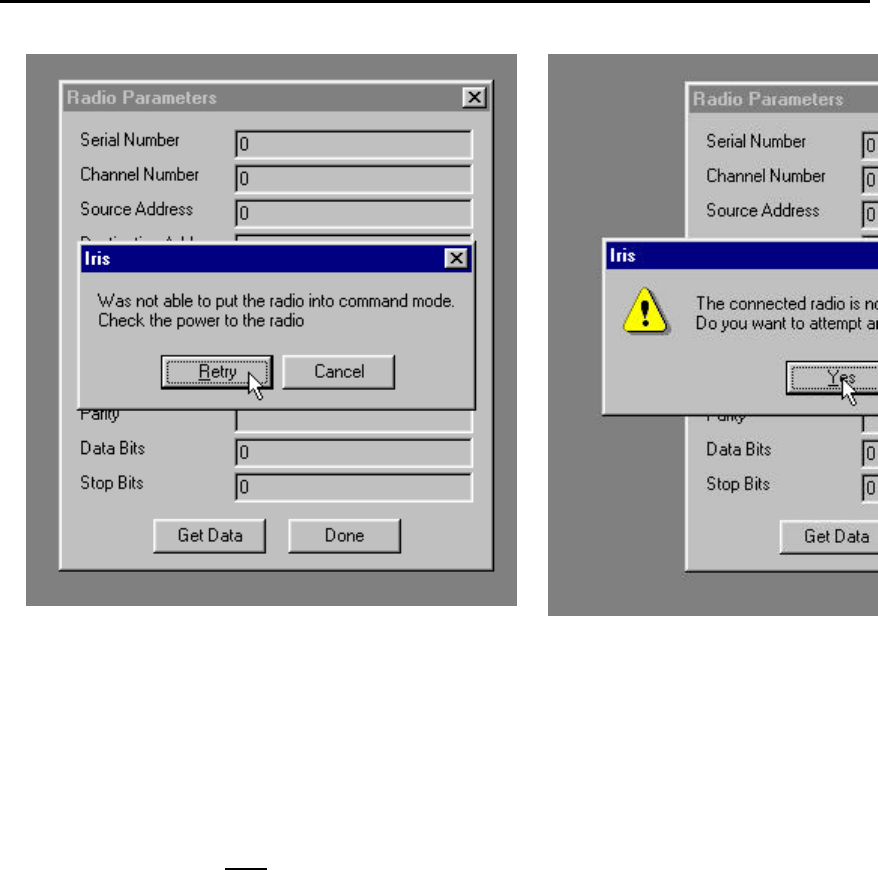
The GET DATA function retrieves the data from the radio that is cabled to the COM port.
Generally a radio is queried if there is a network failure. If there is no communication
between the cabled radio and the Configuration PC an error dialog box will appear..
The DONE button closes the radio parameters dialog.
OS2400 Radio Module Exhibit 21: User Manual 3 FCC ID: OQ7OS2400
49
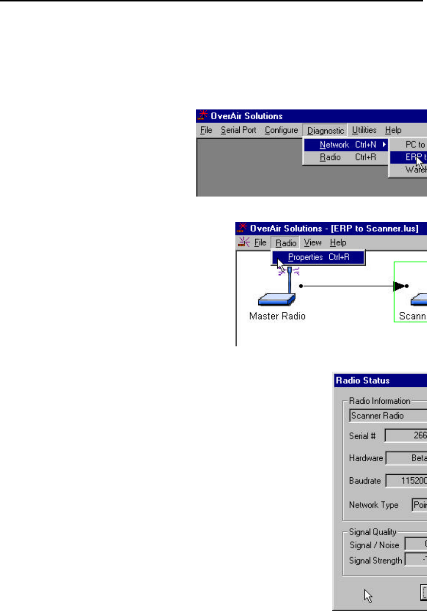
Query a Radio Remotely
If the manufacturer is contacted, Locus Customer Service will ask for software and
hardware revisions and the radio’s serial number. These values are displayed through
the Diagnostic function.
With the Master radio cabled to the
Configuration PC select:
??DIAGNOSTIC
??NETWORK
??the network by name
From the Diagnostic Menu select:
??(highlight) the graphical representation of the
Remote
??RADIO
??PROPERTIES
OR
??quickly double click on the radio’s icon with the left
mouse button
These parameters are displayed in the Radio Status box:
??Radio Name: as defined during network configuration.
??Address: the radio’s address as automatically set during network configuration.
??Serial #: the radio’s serial number as programmed by the manufacturer.
??Firmware: the version number of the software code embedded in the radio.
??Hardware: the version number of the radio’s hardware.
??FPGA: the version number of the Field Programmable Gate Array logic in the radio.
This logic determines the hardware characteristics of the radio.
??Baudrate: the baud rate of the radio’s serial port as set during radio configuration.
??Channel: the channel of the network of which the radio is a component.
??Network Type: as set during network configuration.
??Signal Quality: parameters which indicate how well the network is operating. The
Remote radio calculates the strength (Signal Strength) of the signal from the Master.
It also calculates the strength of the background noise (interference). The
Signal/Noise value is the ratio of Signal Strength to Noise Strength. Monitoring how
these values change when antennas are moved during installation verification can
ensure that the installation configuration has been optimized. The larger the
Signal/Noise ratio, the better performance of the network.
OS2400 Radio Module Exhibit 21: User Manual 3 FCC ID: OQ7OS2400
50
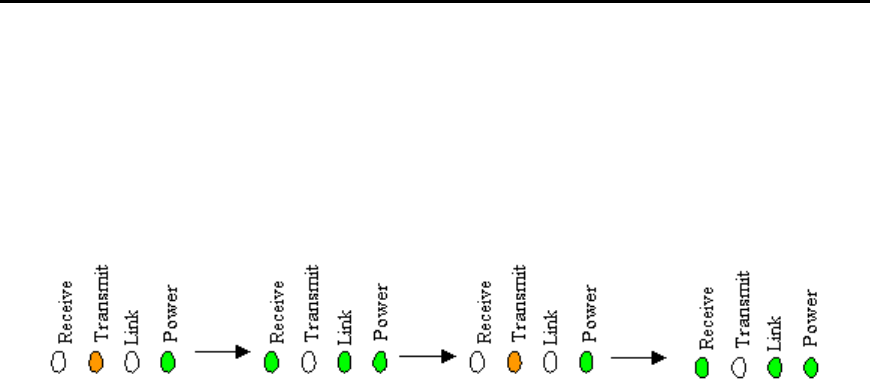
Radios do not communicate
??Radio is in “bootloader” mode:
If the cause of the problem is that the radio is in bootloader mode the diagnostic LEDs
on the radio will flash in the following sequence.
Software must be re-loaded from the Download Code CD. See Download Code for
instructions.
??The correct radio parameters have not been downloaded into the radio. The
OS2400 Setup/Diagnostic Application keeps track of all network and radio
configurations in a database that is embedded in its software. If there is a
mismatch between the parameters in the database and those embedded in the
radio, network function may fail. To check that these two lists match:
??print the network’s configuration from the Configure screen
??query the network’s radios directly or remotely
These values must match: channel, source address and destination address. If they
do not, the radio must be re-configured.
??A radio is locked in “Command Mode”. Power cycle the radio.
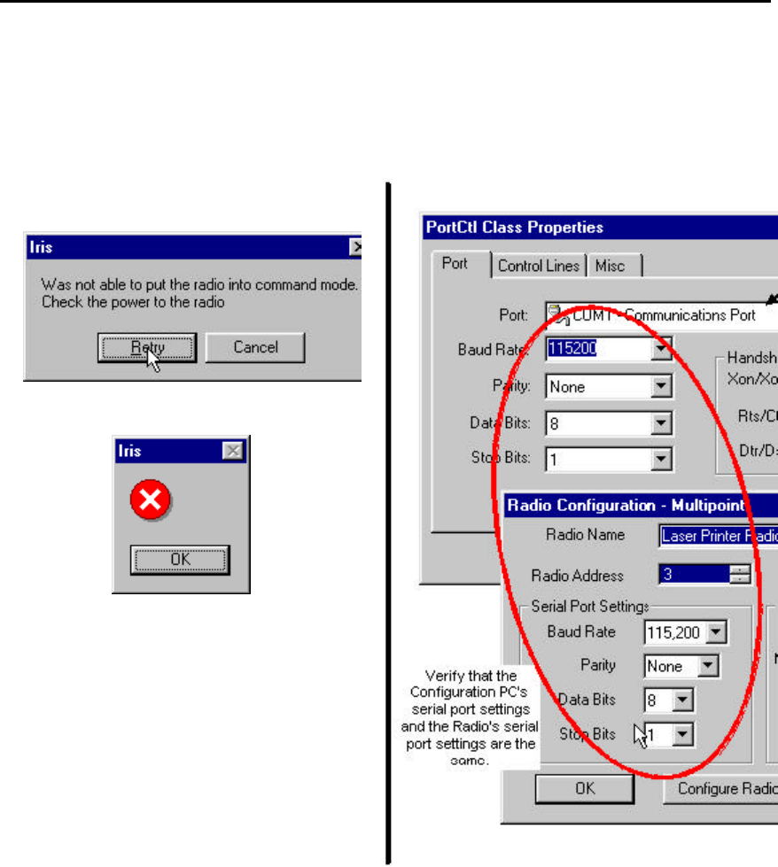
??The Serial Port Settings of the Configuration PC are not the same as those of the
radio cabled to it.
If the serial port settings are not the same there can be no communication between the
two devices.
The first error message will question whether the DC power
connection to the radio is intact.
When RETRY is selected, the OS2400
diagnostic function will suggest that it
perform an auto detection sequence.
OS2400 Radio Module Exhibit 21: User Manual 3 FCC ID: OQ7OS2400
51
Automatic Serial Port Check
If the auto detection sequence is invoked, the OS2400 diagnostic function will attempt to
communicate with the radio using all available serial port parameters. Because there
are so many serial port parameters and therefore many available combinations the auto
detection sequence is very time consuming. If the correct serial port parameters are
known for the particular radio, set the Configuration PC’s serial port to match that of the
radio. Don’t rely on the auto detect sequencing process to reset the radio. Once
communication is reestablished, the radio can be reconfigured as required. The new
serial port settings become the current settings after the radio is reset (or power cycled).
OS2400 Radio Module Exhibit 21: User Manual 3 FCC ID: OQ7OS2400
52
Can’t Configure a Radio
If either of these error dialog messages appear
during CONFIGURE RADIO,
check that the green POWER LED is lit on the
radio.
If the power connection to the radio is intact,
compare the Radio’s serial port settings to that
of the Configuration PC’s serial port.

OS2400 Radio Module Exhibit 21: User Manual 3 FCC ID: OQ7OS2400
53
Contact the Manufacturer
The Manufacturer can be contacted if customer support is needed.
Before contacting the manufacturer, please have this information ready.
??the radio’s serial #
??firmware version
??hardware version
??FPGA version
To obtain this information the radio must be queried.
Put Logo here Locus, Inc.
Fitchburg Center
Madison, Wisconsin 53711
USA
phone: 608-270-0500
fax: 608-270-5257
Reference Information
Help on Windows Help
Serial Port Basics

OS2400 Radio Module Exhibit 21: User Manual 3 FCC ID: OQ7OS2400
54
Glossary
Broadcast Point-Multipoint Network
This is network type where a single master radio sends data to every remote radio in the
network. This is done repeatedly until every remote receives and acknowledges the
data individually. Each remote sends pending data to the master which receives and
acknowledges data sent from each remote. There are multiple remotes for a single
master in this configuration.
Modbus Point-Multpoint Network
This is network with a single Master Radio and multiple Remotes. The devices cabled to
the radios communicate through the Modbus standard protocol. The Master sends data
to a Remote based on the Modbus address of the Modbus device. The data is only sent
to the one Remote device based on its address. Each Remote sends its data only to the
Master. The Master and Remotes acknowledge that the data was received correctly.
Peer to Peer Network
In a Peer-to-Peer network each radio has the ability to receive data from and transmit
data to any other radio in the network.
Point to Point Network
A network consisting of a single master and a single remote radio. All data from the
Master is received and acknowledged by the one Remote. All data from the one
Remote is received and acknowledged by the Master radio.
On-Line Help Options
For further information on the help system itself, merely type F1 after selecting the help
topics option to bring up information on the operation of the help system.

OS2400 Radio Module Exhibit 21: User Manual 3 FCC ID: OQ7OS2400
55
Index
”
”Viewing” a Network’s Function............................................................................................44
A
Adding Radios for Point Multipoint...........................................................................................23
Antenna Selection....................................................................................................................19
Antenna Types Illustrated.......................................................................................................21
Approved Antennas.................................................................................................................. 5
Automatic Arranging of Network Icons .................................................................................43
Automatic Serial Port Check ..................................................................................................51
B
Broken Links in Point-Multipoint Network ...........................................................................46
Broken RF Links .....................................................................................................................45
C
Cable Specifications ..................................................................................................................10
Can’t Configure a Radio .........................................................................................................52
Change a Network’s Channel .................................................................................................35
Channels ...................................................................................................................................15
Configure a New Network.........................................................................................................22
Configure the Radios.................................................................................................................29
Configuring Your Serial Port .................................................................................................11
Contact the Manufacturer ..........................................................................................................53
D
Define Name Type Channel.....................................................................................................22
Delete a Radio...........................................................................................................................27
E
Establish the Graphical Communication Link between Radios ...................................................26
F
FCC Compliance Statement ................................................................................................ 4
Functional Conventions............................................................................................................ 9
G
Gain / User Proximity to Antenna ........................................................................................... 5
Glossary ...................................................................................................................................54
Graphical Layout Screen........................................................................................................22
M
Max Antenna Gain / Output Power......................................................................................... 6
Modifying an Existing Network..........................................................................................33
Move Radios .............................................................................................................................24
N
Network Types..........................................................................................................................15

OS2400 Radio Module Exhibit 21: User Manual 3 FCC ID: OQ7OS2400
56
O
On-Line Help...........................................................................................................................54
P
Point Multipoint Networks ........................................................................................................15
Point to Point Networks.............................................................................................................15
Point-Multipoint ....................................................................................................................16
Print the Network’s Configuration.........................................................................................39
Print the Setup.........................................................................................................................39
Printer Settings........................................................................................................................39
Q
Query a Radio..........................................................................................................................47
Query a Radio Remotely .........................................................................................................49
R
Radio Network Defined.............................................................................................................14
Radio Power Requirements........................................................................................................10
Radio’s Address-an explanation .............................................................................................38
Radios do not communicate ....................................................................................................50
Rename Radios .........................................................................................................................25
S
Save the Network’s Definition...................................................................................................28
Save the Radio’s Configuration .................................................................................................30
Select Radio Color...................................................................................................................37
Serial Port Basics.....................................................................................................................53
Serial Port Factory Defaults Illustrated .................................................................................12
Setting the Serial Port .............................................................................................................11
Setup Overview...................................................................................................................... 7
Site Selection ............................................................................................................................18
Sources of Interference............................................................................................................32
Summary of Function and Use................................................................................................. 3
System Diagnostics an Overview............................................................................................44
T
Test the Installation Plan ........................................................................................................31
The Setup / Diagnostic Software........................................................................................ 8
U
Upgrade Software - Download Code.......................................................................................36
V
Viewing (and Changing) a Radio’s Settings ...........................................................................34
Z
Zoom View of Graphical Layout.............................................................................................40