Proform 831159950 User Manual ELLIPTICAL TRAINER Manuals And Guides L0503376
PROFORM Elliptical Manual L0503376 PROFORM Elliptical Owner's Manual, PROFORM Elliptical installation guides
User Manual: Proform 831159950 831159950 PROFORM ELLIPTICAL TRAINER - Manuals and Guides View the owners manual for your PROFORM ELLIPTICAL TRAINER #831159950. Home:Fitness Equipment Parts:Proform Parts:Proform ELLIPTICAL TRAINER Manual
Open the PDF directly: View PDF ![]() .
.
Page Count: 30

ModelNo.831.159950
SerialNo.
WritetheseriaUnumberinthe
spaceaboveforfuturereference.
SeriaUNumberDecaU(UnderSeat)
• Assembly
• Adjustments
Troubleshooting
PartListandDrawing
Readall precautionsandinstruc-
tions in this manual before us ing
this equipment. Save this manual
for future reference.
ELLmPTICAL TRAINER EXERCISER
User's Manuam
Sears, Roebuck and Co., Hoffman Estates, IL 80179
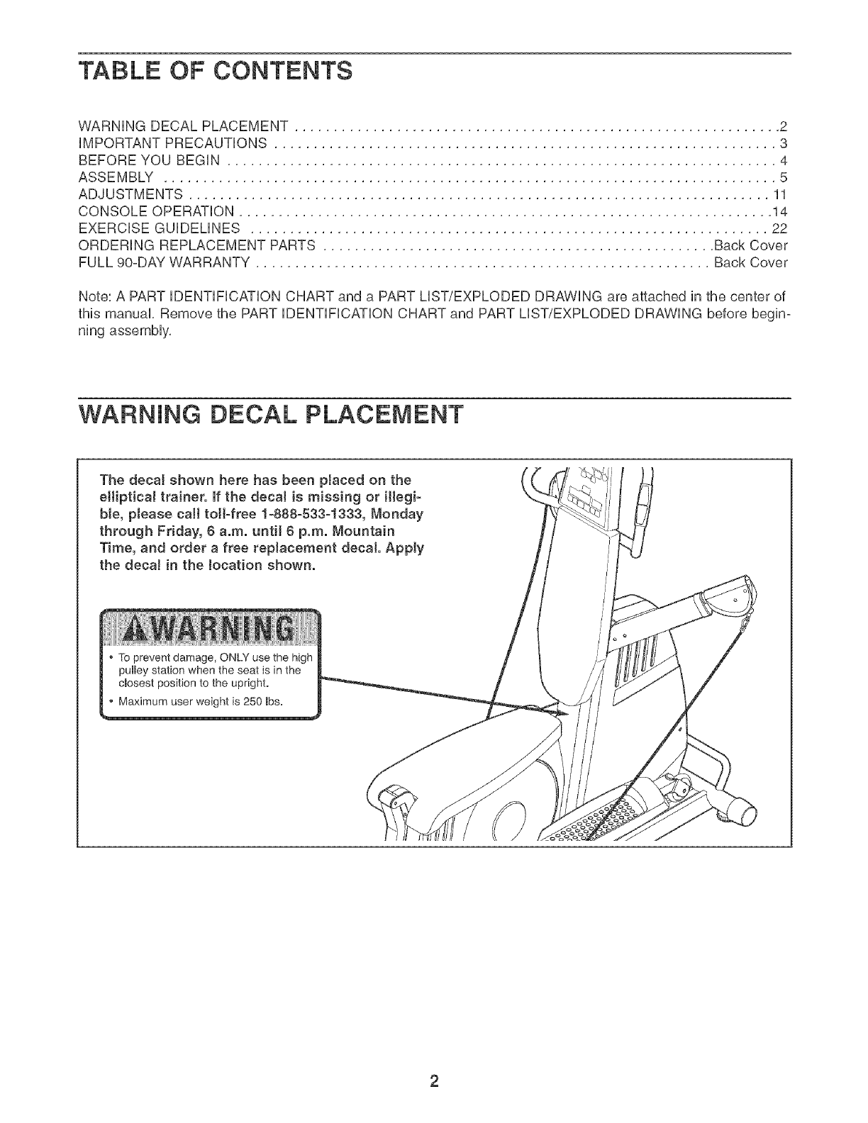
TABLE OF CONTENTS
WARNING DECAL PLACEMENT .............................................................. 2
iMPORTANT PRECAUTIONS ................................................................ 3
BEFORE YOU BEGIN ...................................................................... 4
ASSEMBLY .............................................................................. 5
ADJUSTMENTS .......................................................................... 11
CONSOLE OPERATION .................................................................... 14
EXERCISE GUiDELiNES .................................................................. 22
ORDERING REPLACEMENT PARTS .................................................. Back Cover
FULL 90-DAY WARRANTY .......................................................... Back Cover
Note: A PART iDENTiFiCATiON CHART and a PART LIST/EXPLODED DRAWING are attached in the center of
this manual, Remove the PART iDENTiFiCATiON CHART and PART LIST/EXPLODED DRAWING before begin-
ning assembly,
WARNING DECAL PLACEMENT
The decal shown here has been ptaced on the
eHiptica_ trainer. If the decaJ is missing or illegi-
ble, please call toll-free 1-888-533_1333, Monday
through Friday, 6 a.m. until 6 p.m. Mountain
Time, and order a free replacement decal Apply
the decal in the Jocation shown.
To prevent damage, ONLY use the high
pulley station when the seat is in the
cmosest position to the upright.
Maximum user weight is 250 _bs.

iMPORTANT PRECAUTIONS
AWARNING: Toreducetheriskofse.ousinjury,readthefo,ow ng mportantpreoaut ons
before using the elliptical trainer.
2.
Read aH instructions in this manual before
using the elliptical trainer. Use the elliptical
trainer only as described in this manual
It is the responeibiJity of the owner to ensure
that aH users of the eHipticaJ trainer are ade-
quately informed of aJl precautions.
tf. The elliptical trainer is designed to support a
maximum user weight of 250 pounds.
12. The elliptical trainer is designed to be used
with the included resistance. Do not use the
elliptical trainer with dumbbells or any other
type of weight to increase the resistance.
The elliptical trainer is intended for home use
.
only. Do not use the elliptical trainer in any
commercial, rental, or institutionaJ setting.
4. Use the elliptical trainer only on a level sur-
face. Cover the floor beneath the elliptical
trainer to protect the floor.
Keep the elliptical trainer indoors, away from
moisture and dust. Do not put the elliptical
trainer in a garage or covered patio, or near
water.
13. Make sure that the cables remain on the pul-
leys at aH times, if the cables bind as you are
exercising, atop immediately and make sure
that the cables are on the pulleys. Replace all
cables at least every two years.
14. Hold the handles when mounting, dismount-
ing,or using the elliptical trainer's elliptical
station.
f 5. Always keep your back straight when using
the elliptical trainer; do not arch your back.
8. Make sure that all parts are properly tight-
ened each time the elliptical trainer is used.
FlepJace any worn parts immediately.
9.
Keep children under 12 and pete away from
the elliptical trainer at all times.
18. When you stop using the elliptical station,
allow the pedaJs to slowty come to a stop.
The eiiipticaJ trainer does not have a free-
wheel; the pedaJs will continue to move until
the flywheel stops.
17. Make sure that all eJectdcal connections are
Keep hands and feet away from moving parts, complete before connecting the elliptical
trainer to a power source.
Wear appropriate clothes when exercising;
do not wear loose clothes that couJd become
caught on the elliptical trainer. Always wear
atHetic shoes for foot protection while exer-
cising.
10. The pulse sensor is not a medical device.
Various factors, including the user's move-
ment, may affect the accuracy of heart rate
f 8. Always unplug the power cord immediately
after use and before cleaning the elliptical
trainer.
f9. Use the high pulley station only when the
seat base is collapsed and secured next to
the upright base.
readings. The pulse sensor is intended onJy 20. if you feeJ pain or dizziness at any time while
as an exercise aid in determining heart rate exercising, stop immediately and begin cool-
trends ingeneral, ing down.
, kWARNING: Beforebeginningthisoranyexerciseprogram,coneultyourphye c an.Thee
is especially important far persons over the age of 35 or persons with pre-existing health problems.
Read all instructions before using. Sears assumes no responsibility for personal injury or property
damage sustained by or through the use of this product.
3
BEFORE YOU BEGIN
Thank you for selecting the versatile PROFORM _
CROSSOVER ELLiPTiCAL TRAINER, The elliptbal
trainer offers a selection of weight stations designed to
develop every major muscie group of the body,
Whether your goal is to tone your body, build dramatic
muscie size and strength, or improve your cardiovascu°
iar system, the eiHptbai trainer wHi heip you to achieve
the specific resuits you want,
For your benefit, read this manuaJ carefully before
using the elliptical trainer, if you have questions
after reading this manuai, cali 1-800-4-MYoHOME _>
(1o800o469o4663), To heip us assist you, piease note
the product modei number and seriai number before
calling, The modei number is 831,159950, The seriai
number can be found on a decai attached to the ellipti-
cal trainer (see the front cover of this manual),
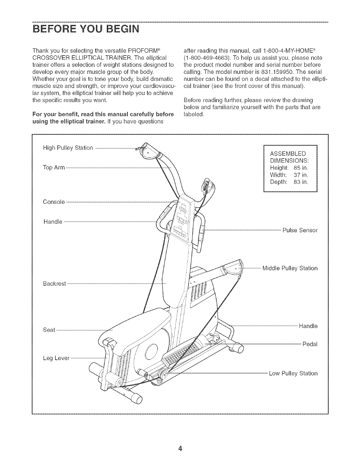
Before reading further, please review the drawing
below and familiarize yourself with the parts that are
labeled,
High Pulley Station
Top Arm
Console
Handle
Backrest
Seat
Leg Lever
ASSEMBLED
DiMENSiONS:
Height: 85 in,
Width: 37 in,
Depth: 83 in,
Pulse Sensor
Handle
Pedal
4
Make Things Easier for Yourself
Everything in this manual is designed to ensure
that the elliptical traiper can be assembled suc-
cessfully by anyone. However. it is important to
realize that the versatile elliptical trainer has
many parts and that the assembly process will
take time. Most people find that ay setting aside
plenty of time assembly will go smoothly.
Before beginning assembly, carefully read the
following information and instructions:
•Assembly requires two persons.
Place all parts in a cleared area and remove the
packing materials. Do not dispose of the packing
materials until assembly is completed.
•Tighten all parts as you assemble them, unless
instructed to do otherwise.
As you assemble the elliptical trainer, make sure
all parts are oriented as shown in the drawings.
For help identifying small parts, use the PART
iDENTiFiCATiON CHART.
The following tooJs (not included} are required
for assembly:
•Two adjustable wrenches
•One rubber mallet
• One Phillips screwdriver
•Lubricant, such as grease or petroleum jelly,
and soapy water.
Assembly wiii be more convenient if you have a
socket set, a set of open-end or closed-end
wrenches, or a set of ratchet wrenches.
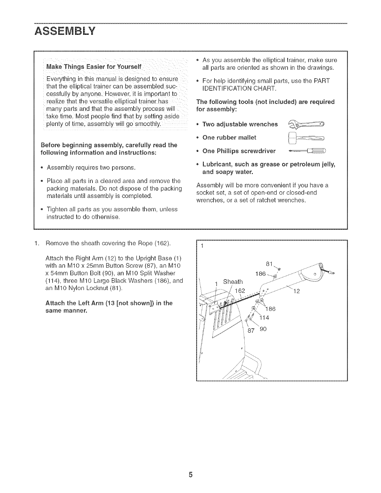
1, Remove the sheath covering the Rope (162),
Attach the Right Arm (12) to the Upright Base (1)
with an MIO x 25mm Button Screw (87), an MIO
x 54mm Button Bolt (90), an MIO Split Washer
(114), three MIO Large Black Washers (186), and
an MIO Nylon Lecknut (81),
Attach the Left Arm (!3 [not shown]} in the
same manner.
1 Sheath
162
81
186
14
87 90
_>_
2, 2
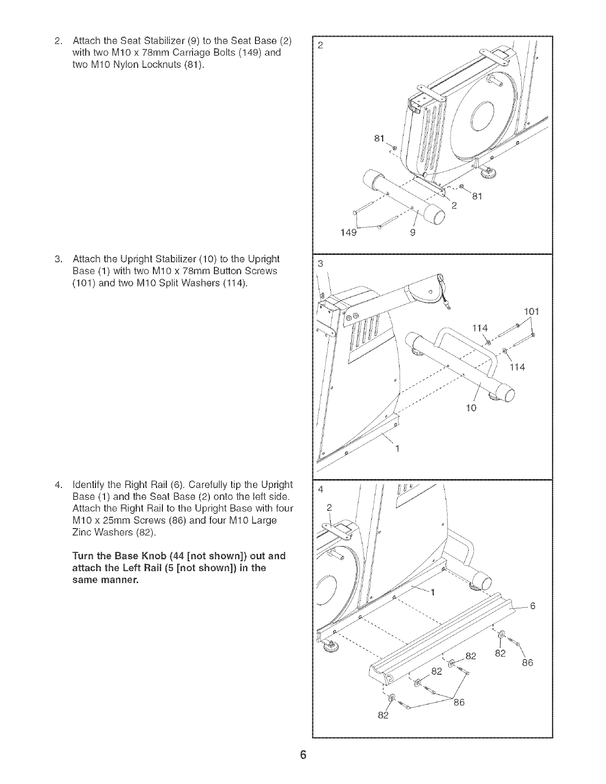
Attach the Seat Stabilizer (9) to the Seat Base (2)
with two MIO x 78mm Carriage BoUts (149) and
two MIO NyUon Locknuts (81),
Attach the Upright Stabilizer (10) to the Upright
Base (1) with two MIO x 78mm Button Screws
(101) and two MIO Split Washers (114),
Udentifythe Right Rail (6), Carefully tip the Upright
Base (1) and the Seat Base (2) onto the Ueftside,
Attach the Right Rail to the Upright Base with four
MIO x 25mm Screws (86) and four MIO Large
Zinc Washers (82),
Turn the Base Knob (44 [not shown]) out and
attach the Left Rail (5 [not shown]) in the
same manner.
3
4
2
81
149 9
114
114
10
82
82
101
86
6
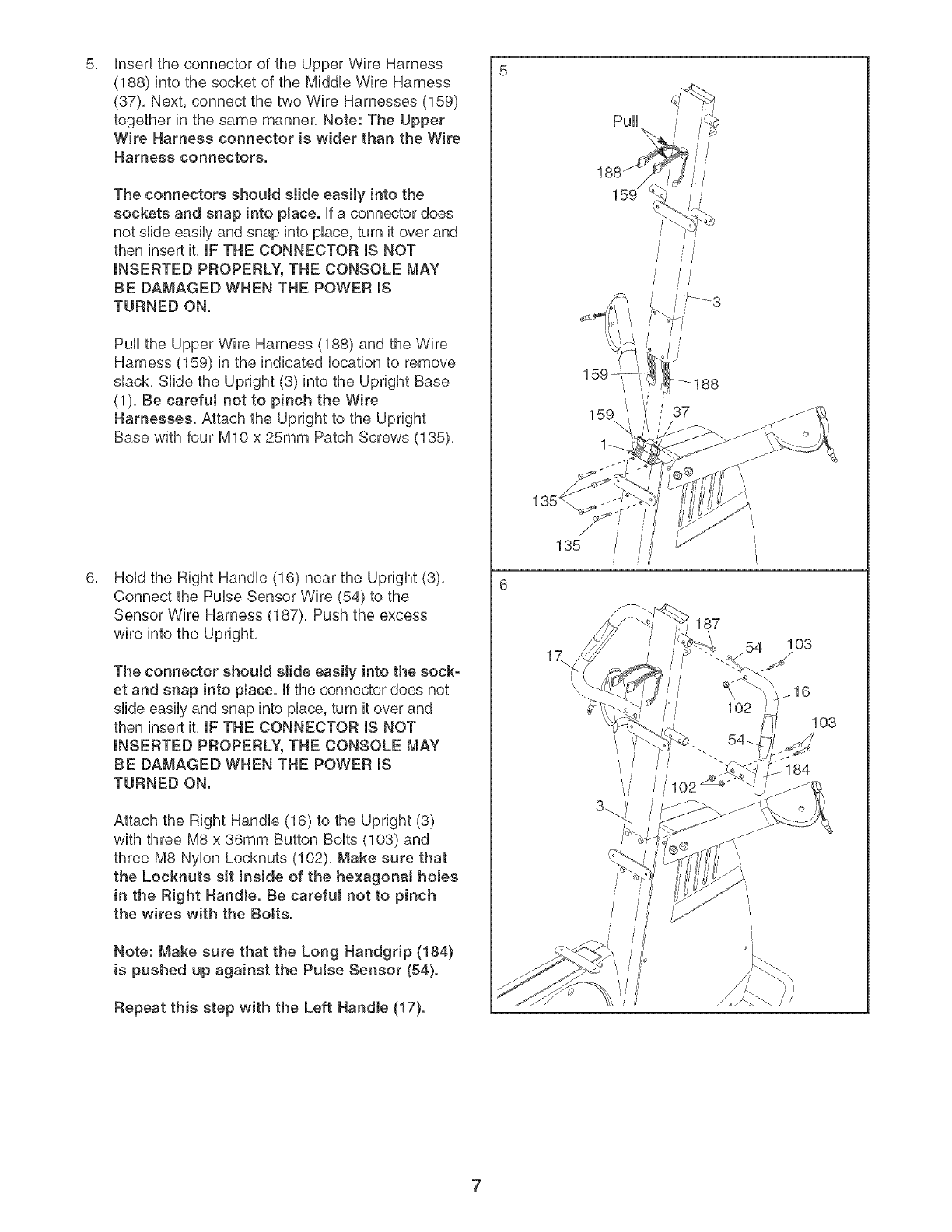
5, 5
insert the connector of the Upper Wire Harness
(188) into the socket of the Middb Wire Harness
(37), Next, connect the two Wire Harnesses (189)
together in the same manner, Note: The Upper
Wire Harness connector is wider than the Wire
Harness connectors.
The connectors should slide easily into the
sockets and snap into place, ff a connector does
not slide easily and snap into place, turn it over and
then insert it, IF THE CONNECTOR IS NOT
INSERTED PROPERLY, THE CONSOLE MAY
BE DAMAGED WHEN THE POWER IS
TURNED ON.
Pull the Upper Wire Harness (188) and the Wire
Harness (159) in the indicated location to remove
slack, Slide the Upright (3) into the Upright Base
(1), Be carefut not to pinch the Wire
Harnesses. Attach the Upright to the Upright
Base with four bt10 x 25mm Patch Screws (135),
Hold the Right Handle (16) near the Upright (3),
Connect the Pulse Sensor Wire (54) to the
Sensor Wire Harness (187), Push the excess
wire into the Upright,
The connector shoutd slide easily into the sock-
et and snap into place, if the connector does not
slide easily and snap into place, turn it over and
then insert it, IF THE CONNECTOR IS NOT
INSERTED PROPERLY, THE CONSOLE MAY
BE DAMAGED WHEN THE POWER IS
TURNED ON.
Attach the Right Handle (16) to the Upright (3)
with three M8 x 36mm Button Bolts (103) and
three M8 Nylon Locknuts (102), Make sure that
the Locknuts sit inside of the hexagona! holes
in the Right Handle. Be careful not to pinch
the wires with the Botts.
Note: Make sure that the Long Handgrip (184)
is pushed up against the Pulse Sensor (54}.
Repeat this step with the Left Handle (17).
/
//
135
187
103
7
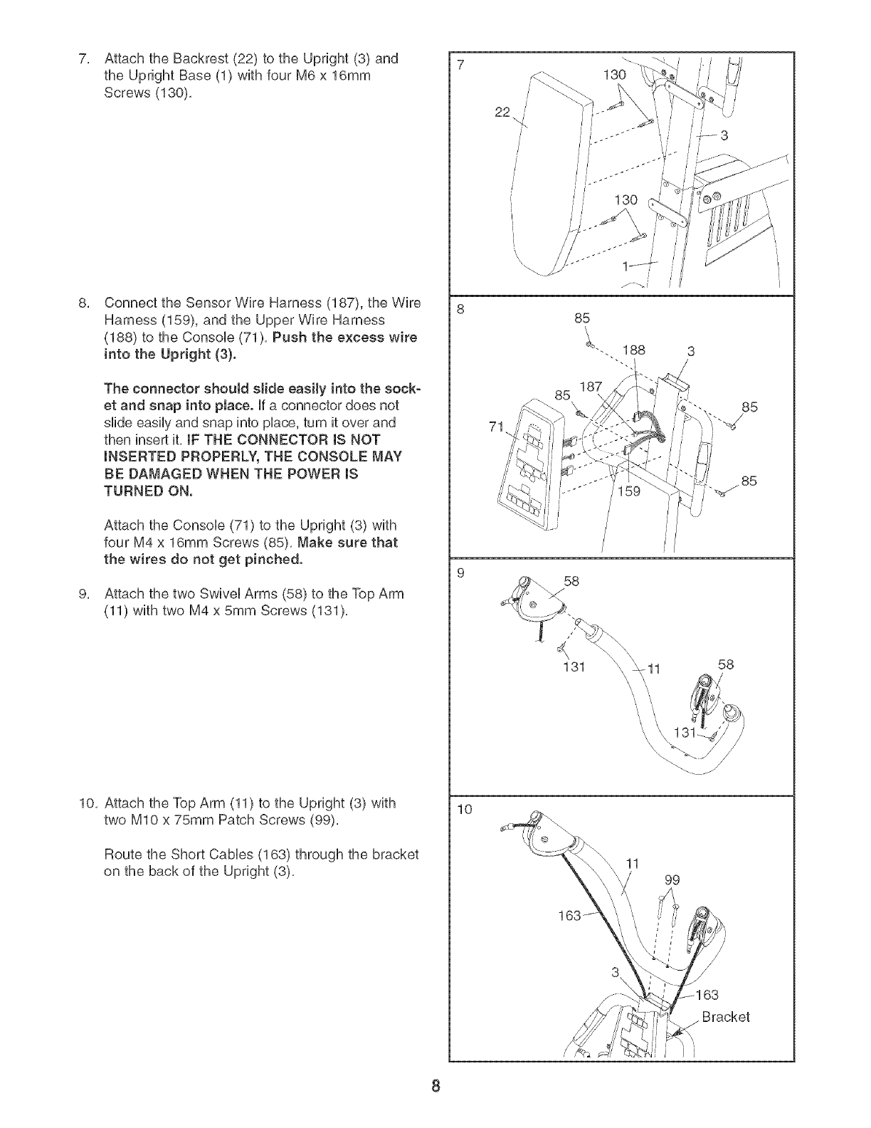
7, Attach the Backrest (22) to the Upright (3) and
the Upright Base (1) with four M6 x 16mm
Screws (130),
Connect the Sensor Wire Harness (187), the Wire
Harness (159), and the Upper Wire Harness
(188) to the ConsoUe (71), Push the excess wire
into the Upright (3}.
The connector shoutd slide easily into the sock-
et and snap into place. Ufa connector does not
slide easily and snap into pUace,turn it over and
then insert it, IF THE CONNECTOR IS NOT
INSERTED PROPERLY, THE CONSOLE MAY
BE DAMAGED WHEN THE POWER mS
TURNED ON.
Attach the ConsoUe (71) to the Upright (3) with
four M4 x 16mm Screws (85), Make sure that
the wires do not get pinched.
Attach the two SwiveUArms (58) to the Top Arm
(11) with two M4 x 5mm Screws (131),
10, Attach the Top Arm (11) to the Upright (3) with
two MIO x 75mm Patch Screws (99),
Route the Short CaMes (163) through the bracket
on the back of the Upright (3),
10
22
71
85 85
_85
58
131 11 58
11 99
3\ \
Bracket
8
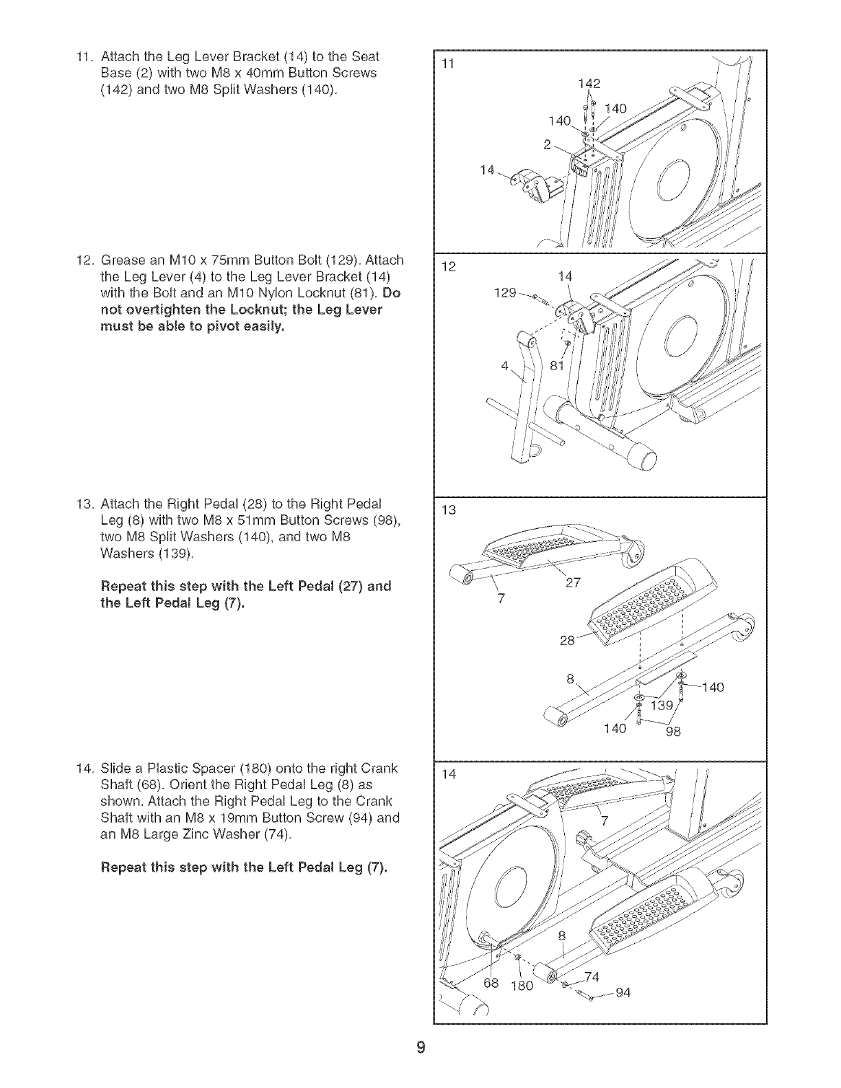
11, Attach the Leg Lever Bracket (14) to the Seat
Base (2) with two M8 x 40mm Button Screws
(142) and two M8 Split Washers (140),
12, Grease an MIO x 75mm Button BoUt(129), Attach
the Leg Lever (4) to the Leg Lever Bracket (14)
with the BoUtand an MIO NyUonLocknut (81), Do
not overtighten the Locknut; the Leg Lever
must be able to pivot easily.
13, Attach the Right PedaU(28) to the Right PedaU
Leg (8) with two M8 x 51mm Button Screws (98),
two M8 Split Washers (140), and two M8
Washers (139),
Repeat this step with the Left Pedal (27} and
the Left PedaJ Leg (7}.
14, SHde a Hastic Spacer (180) onto the right Crank
Shaft (68), Orient the Right PedaU Leg (8) as
shown, Attach the Right PedaU Leg to the Crank
Shaft with an M8 x 19mm Button Screw (94) and
an M8 Large Zinc Washer (74),
Repeat this step with the Left Pedal Leg (7}.
11
12
13
14
14
142
14O
140 98
4O
9
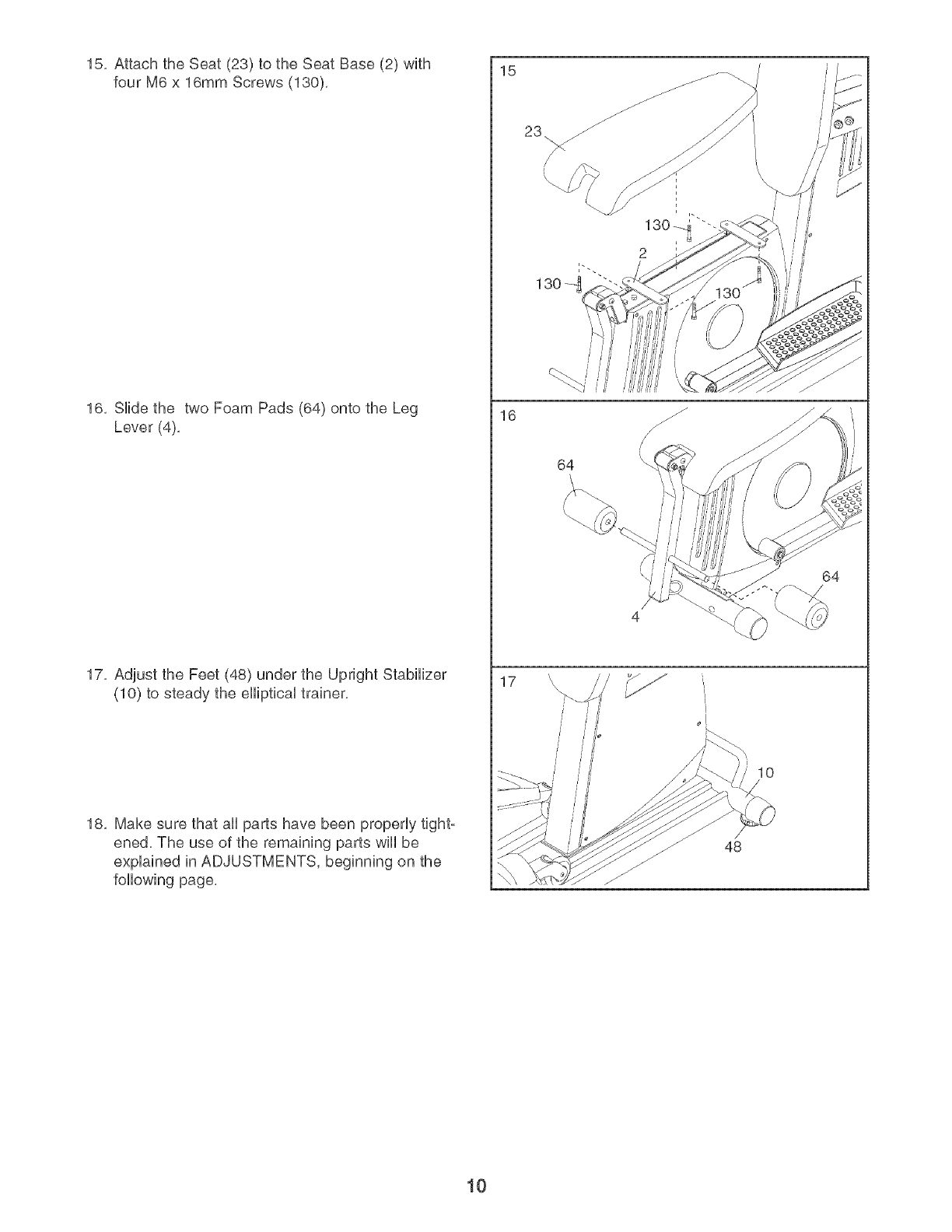
15, Attach the Seat (23) to the Seat Base (2) with
four M6 x 16mm Screws (130),
16, Side the two Foam Pads (64) onto the Leg
Lever (4),
17, Adjust the Feet (48) under the Upright Stabilizer
(10) to steady the eliptical trainer,
18, Make sure that aN parts have been properly tight°
ened, The use of the remaining parts wll be
explained in ADJUSTMENTS, beginning on the
foNowing page,
15
16
17
\
/
/
\
64
\i I
\\
4
L
10
48
64
10
ADJUSTMENTS
This section explains how to adjust the elliptical trainer. See the EXERCISE GUiDELiNES on page 22 for impor-
tant information about how to get the most benefit from your exercise program. Also, refer to the accompanying
exercise guide to see the correct form for each exercise.
Make sure that all parts are properly tightened each time the elliptical trainer is used. Replace any worn parts
immediately. The elliptical trainer can be cleaned with a damp cloth and a mild, non-abrasive detergent. Do not
use solvents.
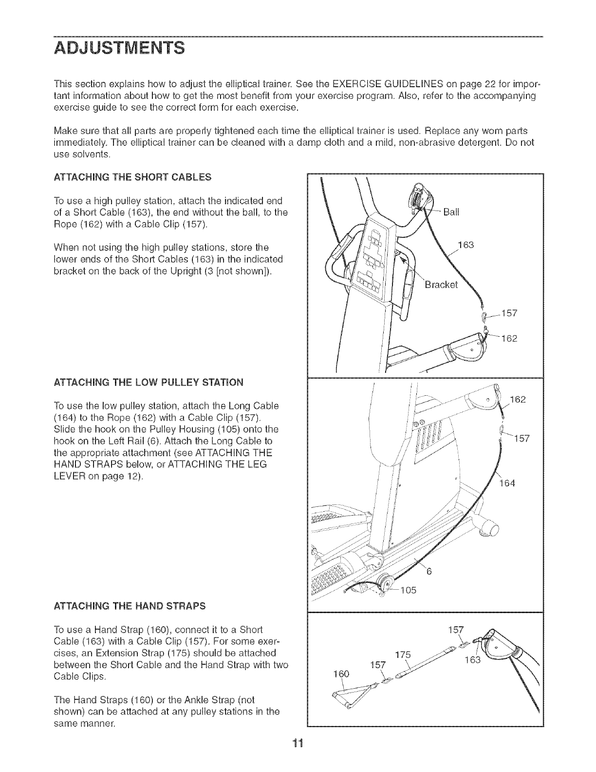
ATTACHING THE SHORT CABLES
To use a high pulley station, attach the indicated end
of a Short Cable (163), the end without the ball, to the
Rope (162) with a Cable Clip (157).
When not using the high pulley stations, store the
lower ends of the Short Cables (163) in the indicated
bracket on the back of the Upright (3 [not shown]),
ATTACHING THE LOW PULLEY STATION
To use the low pulley station, attach the Long Cable
(164) to the Rope (162) with a Cable Clip (157).
Slide the hook on the Pulley Housing (105) onto the
hook on the Left Rail (6). Attach the Long Cable to
the appropriate attachment (see ATTACHING THE
HAND STRAPS below, or ATTACHING THE LEG
LEVER on page 12).
ATTACHING THE HAND STRAPS
To use a Hand Strap (160), connect it to a Short
Cable (163) with a Cable Clip (157). For some exer-
cises, an Extension Strap (175) should be attached
between the Short Cable and the Hand Strap with two
Cable Clips.
The Hand Straps (160) or the Ankle Strap (not
shown) can be attached at any pulley stations in the
same manner.
163
l/
157
160
175
157 163
162
11
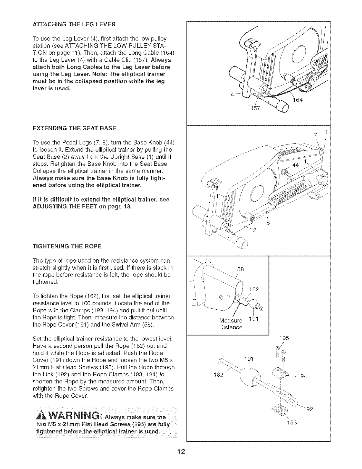
ATTACHmNG THE LEG LEVER
To use the Leg Lever (4), first attach the HowpuHHey
station (see ATTACHING THE LOW PULLEY STA-
THON on page 11), Then, attach the Long CaMe (164)
to the Leg Lever (4) with a CaMe CHip(157), Always
attach both Long Cabtes to the Leg Lever before
using the Leg Lever. Note: The etliptica! trainer
must be in the collapsed position while the teg
tever is used.
EXTENDING THE SEAT BASE
To use the PedaH Legs (7, 8), turn the Base Knob (44)
to Hoosenit, Extend the eHHpticaHtrainer by puHHngthe
Seat Base (2) away from the Upright Base (1) until it
stops, Retighten the Base Knob into the Seat Base,
CoHHapsethe eHHpticaHtrainer in the same manner,
Always make sure the Base Knob is fulty tight-
ened before using the eHipticaJ trainer.
mfit is difficult to extend the elliptical trainer, see
ADJUSTING THE FEET on page 13.
TIGHTENING THE ROPE
The type of rope used on the resistance system can
stretch slightly when it is first used, if there is shack in
the rope before resistance is felt, the rope should be
tightened,
To tighten the Rope (162), first set the elliptical trainer
resistance level to 100 pounds, Locate the end of the
Rope with the CHamps(193, 194) and puil it out until
the Rope is tight, Then, measure the distance between
the Rope Cover (191 ) and the Swivel Arm (58),
Set the elliptical trainer resistance to the lowest level,
Have a second person puil the Rope (162) out and
hold it while the Rope is adjusted, Push the Rope
Cover (191) down the Rope and loosen the two M5 x
21mm Fiat Head Screws (195), Puil the Rope through
the Link (192) and the Rope Clamps (193, 194) to
shorten the Rope by the measured amount, Then,
retighten the two Screws and cover the Rope Clamps
with the Rope Cover.
two M5 × 21ram Flat Head Screws (! 95} are fully
164
157
58
162
Measure 191
Distance
195
191
162 \
193
194
192
12
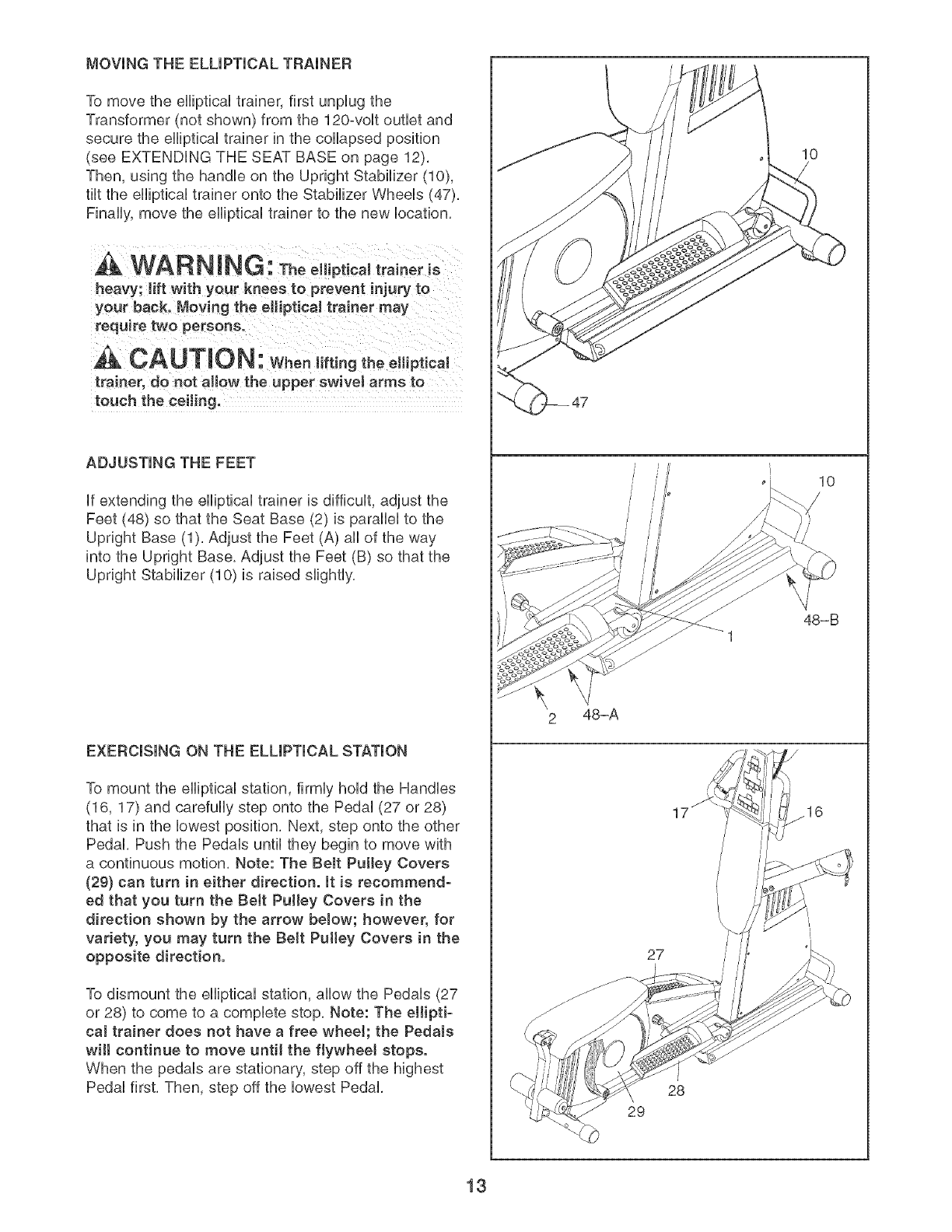
MOVING THE ELUPTmCAL TRAINER
To move the eflipticaU trainer, first unpUugthe
Transformer (not shown) from the 120-voUt outlet and
secure the eflipticaU trainer in the coflapsed position
(see EXTENDUNG THE SEAT BASE on page 12).
Then, using the handUeon the Upright Stabilizer (10),
tilt the eflipticaUtrainer onto the Stabilizer WheeUs (47).
Finafly, move the efliptical trainer to the new location.
WARN ING: Theelliptical traineris
heavy; lift with your knees to prevent injury to
your back. Moving the elliptical trainer may
require two persons.
CAUTION: When,ftingtheelliptical
trainer, do not aJiow the upper swivel arms to
touch the ceiJing.
ADJUSTING THE FEET
If extending the elliptical trainer is difficult, adjust the
Feet (48) so that the Seat Base (2) is parallel to the
Upright Base (1). Adjust the Feet (A) all of the way
into the Upright Base. Adjust the Feet (B) so that the
Upright Stabilizer (10) is raised slightly.
EXERCISING ON THE ELLIPTICAL STATION
To mount the elliptical station, firmly hold the Handles
(16, 17) and carefully step onto the Pedal (27 or 28)
that is in the lowest position. Next, step onto the other
Pedal. Push the Pedals until they begin to move with
a continuous motion. Note: The BeJt Pulley Covers
(29} can turn in either direction, it is recommend-
ed that you turn the BeJt Pulley Covers in the
direction shown by the arrow below; however, for
variety, you may turn the Belt Puttey Covers in the
opposite direction.
To dismount the elliptical station, allow the Pedals (27
or 28) to come to a complete stop. Note: The ellipti-
cal trainer does not have a free whee!; the Pedals
wilt continue to move until the flywheel stops.
When the pedals are stationary, step off the highest
Pedal first. Then, step off the lowest Pedal.
2 48-A
17
27
28
29
10
10
48-B
16
13
CONSOLE OPERATION
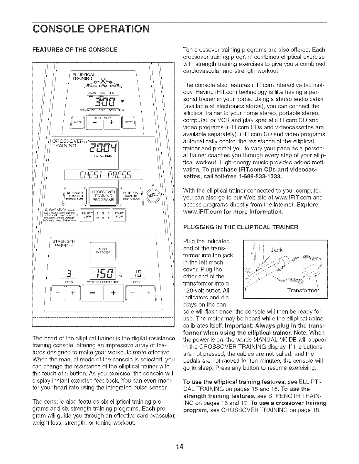
FEATURES OF THE CONSOLE
TRAiNiNG 1
NEXT
EXEROISE
ts ]
SETS SYSTEM RESISTAN©E REPS
The heart of the efliptbal trainer is the digital resistance
training consob, offering an impressive array of fea-
tures designed to make your workouts more effective,
When the manual mode of the consob is sebcted, you
can change the resistance of the efliptbal trainer with
the touch of a button, As you exercise, the consob wifl
display instant exercise feedback, You can even moni-
tor your heart rate using the integrated pube sensor,
The consob also features six efliptbal training pro-
grams and six strength training programs, Each pro-
gram will guide you through an effective cardiovascular,
weight loss, strength, or toning workout,
Ten crossover training programs are also offered, Each
crossover training program combines elliptical exercise
with strength training exercises to give you a combined
cardiovascular and strength workout,
The console also features iFIT,com interactive technol-
ogy, Having iFIT,com technology is like having a per-
sonal trainer in your home, Using a stereo audio cable
(available at electronics stores), you can connect the
elliptical trainer to your home stereo, portable stereo,
computer, or VCR and play special iFIT,com CD and
video programs (iFIT,com CDs and videocassettes are
available separately), iFIT,com CD and video programs
automatically control the resistance of the elliptical
trainer and prompt you to vary your pace as a person-
al trainer coaches you through every step of your ellip-
tical workout, High-energy music provides added moti-
vation, To purchase iFIT.com CDs and videocas-
settes, call toil-free 1-888-533-1333.
With the elliptical trainer connected to your computer,
you can also go to our Web site at www, iFIT,com and
access programs directly from the internet, Explore
wwwJFITocom for more information.
PLUGGING iN THE ELLiPTiCAL TRAINER
Hug the indicated ,
end of the trans- Jack
former into the jack
in the left mech
cover, Hug the
other end of the
transformer into a
120-volt outlet, All Transforme
indicators and dis-
plays on the con-
sob will flash once; the console will then be ready for
use, The motor may be heard while the elliptical trainer
calibrates itself, important: AJways plug in the trans-
former when using the elliptical trainer. Note: When
the power is on, the words MANUAL MODE will appear
in the CROSSOVER TRAiNiNG display, if the buttons
are not pressed, the cables are not puffed, and the
pedals are not moved for ten minutes, the console will
go to sleep, Press any button to resume exercising,
To use the elliptical training features, see ELLiPTi-
CAL TRAiNiNG on pages 15 and 16, To use the
strength training features, see STRENGTH TRAiN-
iNG on pages 16 and 17, To use a crossover training
program, see CROSSOVER TRAiNiNG on page 18,
14
ELLIPTICALTRAINING
MANUAL OPERATION
1. Plug In the Transformer.
See PLUGGING iN THE ELLIPTICAL TRAINER on
page 14, Important: Always plug in the trans-
former when using the elliptical trainer.
2. Extend the Seat Base.
See EXTENDING THE SEAT BASE on page 12,
3. Select the Manual Mode.
When the transformer is plugged in, the manual
mode will be sebcted, if you have already sebcted
a program, press the ELLiPTiCAL TRAiNiNG
PROGRAMS button repeatedly until the words
MANUAL MODE reappear in the CROSSOVER
TRAiNiNG display,
4. Begin Pedaling and Select a Resistance Level.
To reset the display modes to their default settings,
press the RESET button, The SCAN display mode
will be selected,
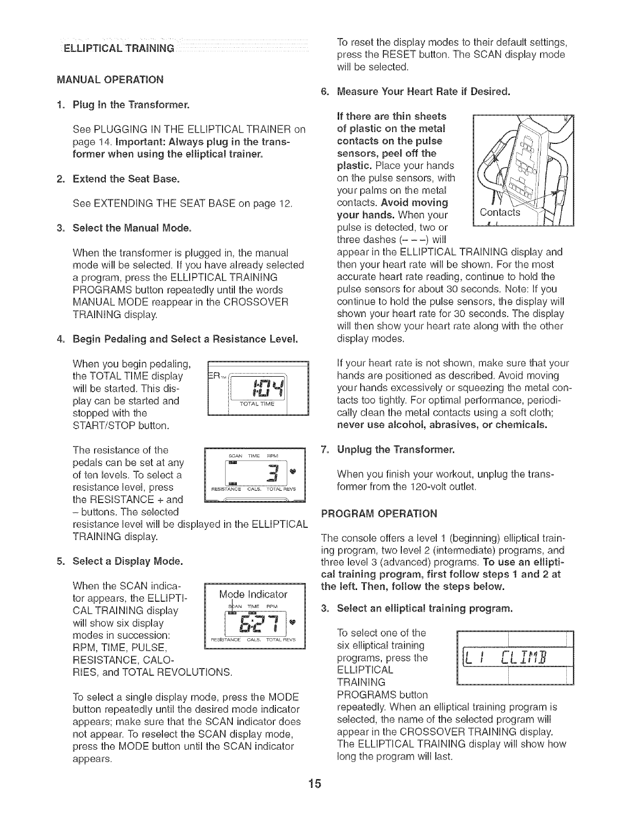
6. Measure Your Heart Rate if Desired.
if there are thin sheets
of plastic on the metal
contacts on the pulse
sensors, peel off the
plastic. Place your hands
on the pulse sensors, with
your palms on the metal
contacts, Avoid moving
your hands. When your
pulse is detected, two or
three dashes (- --) will
Co?acts,
appear in the ELLiPTiCAL TRAiNiNG display and
then your heart rate wiii be shown, For the most
accurate heart rate reading, continue to hold the
pulse sensors for about 30 seconds, Note: if you
continue to hold the pulse sensors, the display will
shown your heart rate for 30 seconds, The display
wiii then show your heart rate along with the other
display modes,
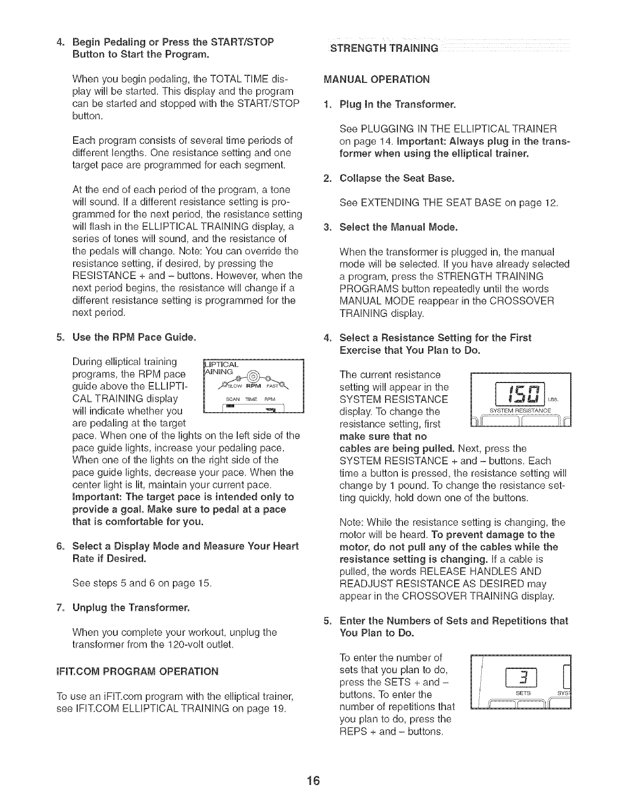
When you begin pedaling,
the TOTAL TiME display
will be started, This dis-
play can be started and
stopped with the
START/STOP button,
if your heart rate is not shown, make sure that your
hands are positioned as described, Avoid moving
your hands excessively or squeezing the metal con=
tacts too tightly, For optimal performance, periodi=
cally clean the metal contacts using a soft cloth;
never use alcohot, abrasives, or chemicals.
The resistance of the
pedals can be set at any
of ten levels, To select a
resistance level, press
the RESISTANCE + and _ ,
- buttons, The selected
resistance level will be displayed in the ELLiPTiCAL
TRAiNiNG display,
SOAN "lIME RPM
[- tel.
REsEsrT_NOE OAKS. 701AL REVS
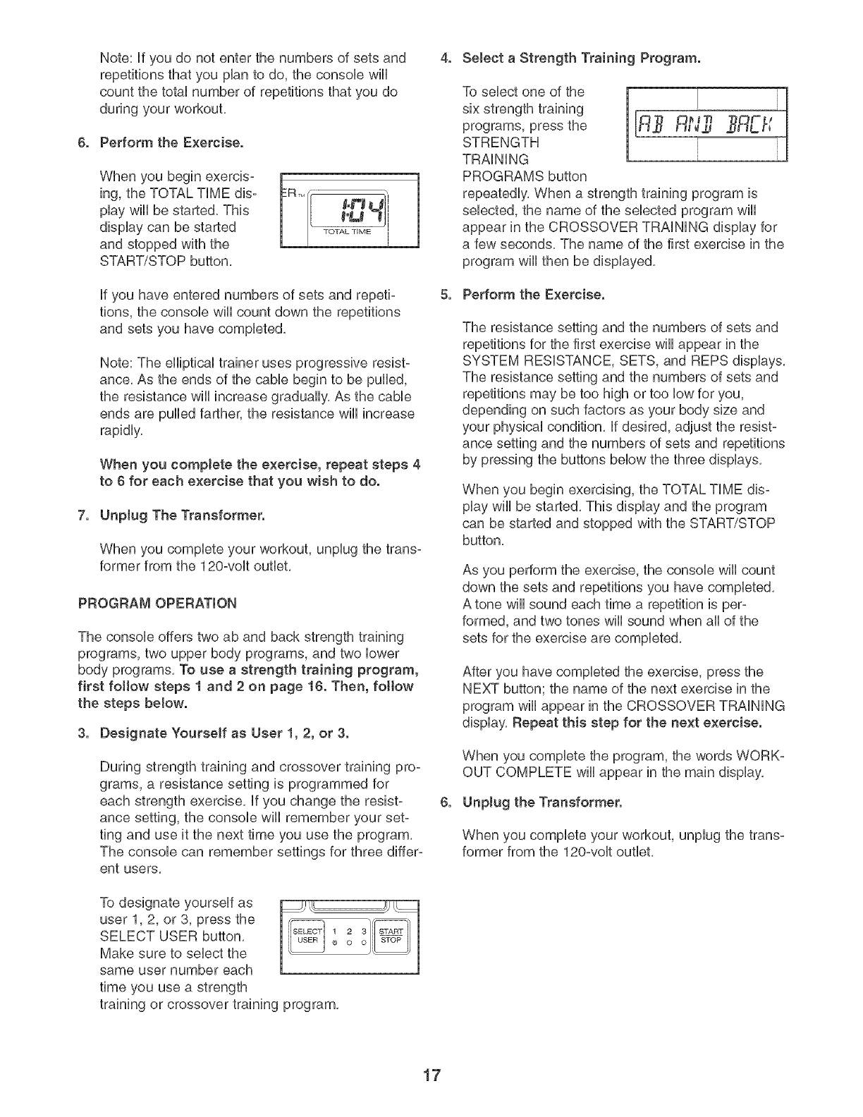
5. Select a Display Mode.
When the SCAN indica=
tor appears, the ELLIPTI=
CAL TRAiNiNG display
wiii show six display
modes in succession:
RPM, TIME, PULSE,
RESISTANCE, CALO=
Mode indicator
S.,o-j
.C I
RESISTANCE OAKS, TOTAL REVS
RIES, and TOTAL REVOLUTIONS,
To select a single display mode, press the MODE
button repeatedly until the desired mode indicator
appears; make sure that the SCAN indicator does
not appear, To reselect the SCAN display mode,
press the MODE button until the SCAN indicator
appears,
7. Unptug the Transformer.
When you finish your workout, unplug the trans-
former from the 120-volt outlet,
PROGRAM OPERATION
The console offers a level 1 (beginning) elliptical train=
ing program, two level 2 (intermediate) programs, and
three level 3 (advanced) programs, To use an eltipti-
caJ training program, first follow steps 1 and 2 at
the teft. Then, fottow the steps below.
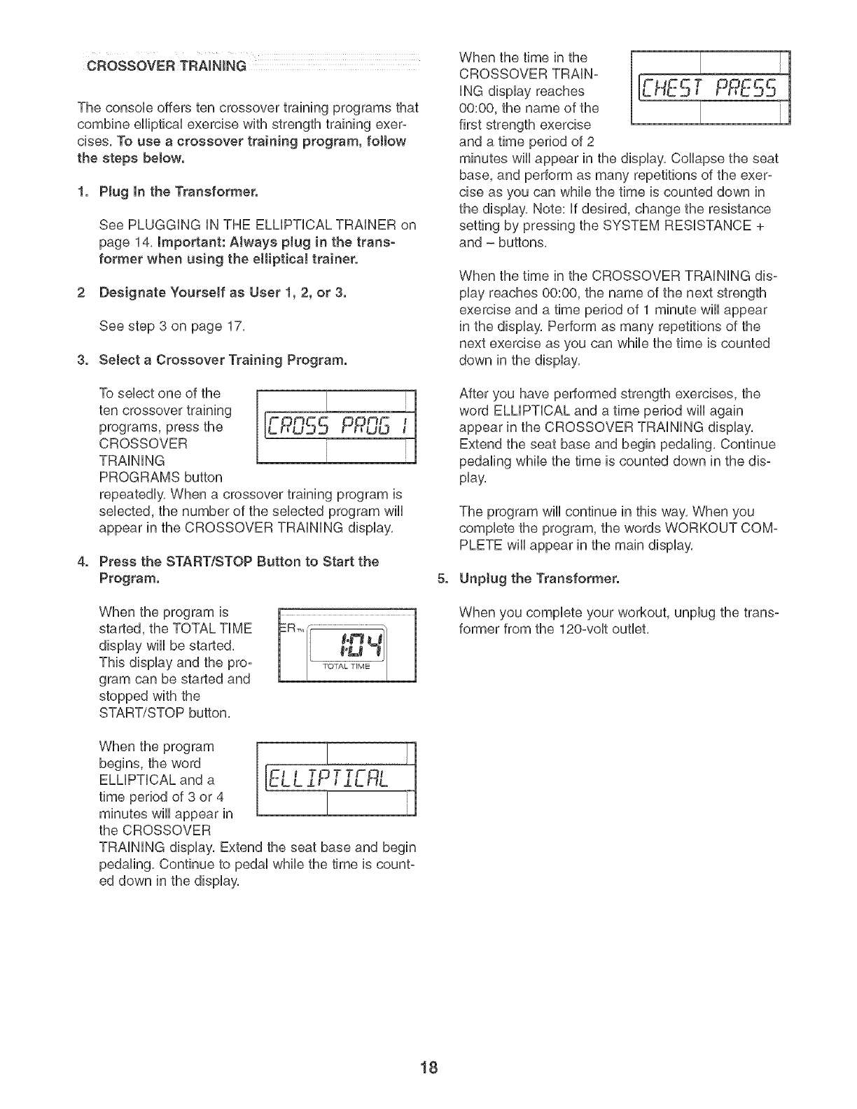
3. Select an elliptical training program.
To select one of the
six elliptical training
programs, press the
ELLiPTiCAL
TRAiNiNG
PROGRAMS button
i
tLL J.a IJJ ..
repeatedly, When an elliptical training program is
selected, the name of the selected program will
appear in the CROSSOVER TRAiNiNG display,
The ELLiPTiCAL TRAiNiNG display wiii show how
long the program will last,
15
,Begin PedaJing or Press the START/STOP
Button to Start the Program.
When you begin pedaling, the TOTAL TiME dis-
play wiii be started. This display and the program
can be started and stopped with the START/STOP
button.
Each program consists of several time periods of
different lengths. One resistance setting and one
target pace are programmed for each segment.
At the end of each period of the program, a tone
will sound, if a different resistance setting is pro-
grammed for the next period, the resistance setting
wiii flash in the ELLiPTiCAL TRAiNiNG display, a
series of tones will sound, and the resistance of
the pedals will change. Note: You can override the
resistance setting, if desired, by pressing the
RESISTANCE + and - buttons. However, when the
next period begins, the resistance will change if a
different resistance setting is programmed for the
next period.
5. Use the RPM Pace Guide.
During elliptical training
programs, the RPM pace
guide above the ELLiPTi-
CAL TRAiNiNG display
wiii indicate whether you
are pedaling at the target
pace. When one of the lights on the left side of the
pace guide lights, increase your pedaling pace.
When one of the lights on the right side of the
pace guide lights, decrease your pace. When the
center light is lit, maintain your current pace.
important: The target pace is intended only to
provide a goa!. Make sure to pedal at a pace
that is comfortable for you.
6. Select a Display Mode and Measure Your Heart
Rate if Desired.
,
See steps 5 and 6 on page 15.
Unplug the Transformer.
When you complete your workout, unplug the
transformer from the 120-volt outlet.
IFIT.COM PROGRAM OPERATION
To use an iFIT.com program with the elliptical trainer,
see IFIT.COM ELLIPTICAL TRAINING on page 19.
STRENGTH TRAINING
MANUAL OPERATION
1. Ptug In the Transformer.
See PLUGGING iN THE ELLIPTICAL TRAINER
on page 14. Important: Always pJug in the trans-
former when using the eJliptical trainer.
2. Cottapse the Seat Base.
See EXTENDING THE SEAT BASE on page 12.
3. SeJect the Manual Mode.
When the transformer is plugged in, the manual
mode wiii be selected, if you have already selected
a program, press the STRENGTH TRAiNiNG
PROGRAMS button repeatedly until the words
MANUAL MODE reappear in the CROSSOVER
TRAiNiNG display.
4, Select a Resistance Setting for the First
Exercise that You Plan to Do,
The current resistance
settingwillappearinthe [ I_ _'l}
SYSTEM RESISTANCE _,_ L_
display. To change the sYSTEMRESISTANCE
resistance setting, first
make sure that no
cables are being pulled. Next, press the
SYSTEM RESISTANCE + and - buttons. Each
time a button is pressed, the resistance setting will
change by 1 pound. To change the resistance set-
ting quickly, hold down one of the buttons.
Note: While the resistance setting is changing, the
motor wili be heard. To prevent damage to the
motor, do not pull any of the cabJes while the
resistance setting is changing, if a cable is
pulled, the words RELEASE HANDLES AND
READJUST RESISTANCE AS DESIRED may
appear in the CROSSOVER TRAiNiNG display.
5. Enter the Numbers of Sets and Repetitions that
You Ptan to Do,
To enter the number of
sets that you plan to do,
press the SETS + and -
buttons. To enter the
number of repetitions that
you plan to do, press the
REPS + and - buttons.
16
Note: if you do not enter the numbers of sets and
repetitions that you plan to do, the consob will
count the total number of repetitions that you do
during your workout,
6. Perform the Exercise.
When you begin exercis- R_M[f ",
ing, the TOTAL TiME dis- 84_'_mo#l
play wiii be started, This 1 [ _°L_ _ i
display can be started TOTAL_'_ME
and stopped with the
START/STOP button,
if you have entered numbers of sets and repeti-
tions, the console wiii count down the repetitions
and sets you have completed,
Note: The elliptical trainer uses progressive resist-
ance, As the ends of the cable begin to be pulled,
the resistance will increase gradually, As the cable
ends are pulled farther, the resistance will increase
rapidly,
When you complete the exercise, repeat steps 4
to 6 for each exercise that you wish to do.
7. Unplug The Transformer.
When you complete your workout, unplug the trans-
former from the 120-volt outlet,
PROGRAM OPERATION
The console offers two ab and back strength training
programs, two upper body programs, and two lower
body programs, To use a strength training program,
first follow steps 1 and 2 on page 16. Then, fottow
the steps below.
3. Designate Yourself as User 1, 2, or 3.
During strength training and crossover training pro-
grams, a resistance setting is programmed for
each strength exercise, if you change the resist-
ance setting, the console will remember your set-
ting and use it the next time you use the program,
The console can remember settings for three differ-
ent users,
To designate yourself as
user 1,2, or 3, press the
SELECT USER button,
Make sure to select the
same user number each
time you use a strength
1 2 3 _"
0 o o
training or crossover training program,
4. Select a Strength Training Program.
To select one of the
six strength training
programs, press the
STRENGTH
TRAiNiNG
PROGRAMS button
repeatedly, When a strength training program is
selected, the name of the selected program wiii
appear in the CROSSOVER TRAiNiNG display for
a few seconds, The name of the first exercise in the
program will then be displayed,
5. Perform the Exercise.
The resistance setting and the numbers of sets and
repetitions for the first exercise will appear in the
SYSTEM RESISTANCE, SETS, and REPS displays,
The resistance setting and the numbers of sets and
repetitions may be too high or too low for you,
depending on such factors as your body size and
your physical condition, if desired, adjust the resist-
ance setting and the numbers of sets and repetitions
by pressing the buttons below the three displays,
When you begin exercising, the TOTAL TiME dis-
play will be started, This display and the program
can be started and stopped with the START/STOP
button,
As you perform the exercise, the console wiii count
down the sets and repetitions you have completed,
A tone will sound each time a repetition is per-
formed, and two tones wiii sound when aii of the
sets for the exercise are completed,
After you have completed the exercise, press the
NEXT button; the name of the next exercise in the
program will appear in the CROSSOVER TRAiNiNG
display, Repeat this step for the next exercise.
When you complete the program, the words WORK-
OUT COMPLETE will appear in the main display,
6. Unplug the Transformer.
When you complete your workout, unplug the trans-
former from the 120-volt outlet,
17
The console offers ten crossover training programs that
combine elliptical exercise with strength training exer-
cises. To use a crossover training program, fottow
the steps below.
1. Plug In the Transformer.
See PLUGGING IN THE ELMPTICAL TRAINER on
page 14, important: Always plug in the trans-
former when using the eJlipticai trainer.
2 Designate Yourself as User 1, 2, or 3.
See step 3 on page 17,
3. Select a Crossover Training Program.
To sebct one of the
ten crossover training
programs, press the
CROSSOVER
TRAINING
PROGRAMS button
repeatedly. When a crossover training program is
sebcted, the number of the sebcted program wiiI
appear in the CROSSOVER TRAINING display.
4. Press the STARTtSTOP Sutton to Start the
Program.
When the program is
started, the TOTAL TIME
display wiiI be started.
This display and the pro-
gram can be started and
stopped with the
START/STOP button,
_-e -B
When the program
begins, the word
ELLIPTICAL and a
time period of 3 or 4
minutes will appear in
the CROSSOVER
TRAINING display, Extend the seat base and begin
pedaling, Continue to pedal while the time is count-
ed down in the display,
When the time in the
CROSSOVER TRAiN-
iNG display reaches
00:00, the name of the
first strength exercise
and a time period of 2
minutes will appear in the display. Collapse the seat
base, and perform as many repetitions of the exer-
cise as you can while the time is counted down in
the display. Note: if desired, change the resistance
setting by pressing the SYSTEM RESISTANCE +
and - buttons.
When the time in the CROSSOVER TRAiNiNG dis-
play reaches 00:00, the name of the next strength
exercise and a time period of 1 minute will appear
in the display, Perform as many repetitions of the
next exercise as you can while the time is counted
down in the display,
After you have performed strength exercises, the
word ELLiPTiCAL and a time period wiii again
appear in the CROSSOVER TRAiNiNG display.
Extend the seat base and begin pedaling. Continue
pedaling while the time is counted down in the dis-
play.
The program will continue in this way. When you
complete the program, the words WORKOUT COM-
PLETE wiii appear in the main display.
5. Unptug the Transformer.
When you complete your workout, unplug the trans-
former from the 120-volt outlet.
18
IFIT.COM CD AND VIDEO PROGRAMS
To use iFIT,com CDs or videocassettes, the elliptical
trainer must be connected to your portabb CD player,
portabb stereo, home stereo, computer with CD play-
er, or VCR, See HOW TO CONNECT YOUR CD
PLAYER, VCR, OR COMPUTER on pages 20 and 21,
To purchase iFIT.com CDs and videocassettes, call
toll-free 1-833-533-1333. Follow the steps below to
use an iFIT.com CD or video program.
1. Plug In the Transformer.
See PLUGGING iN THE ELMPTICAL TRAINER on
page 14, Important: Always plug in the trans-
former when using the elliptical trainer.
2. Extend the Seat Base.
See EXTENDING THE SEAT BASE on page 12,
3. Select the iFIT.com Mode.
To select the iFIT,com mode, press the iFIT,com
button, The indicator above the button will light,
and the words IFIT MODE will appear in the
CROSSOVER TRAiNiNG display,
4. Insert the iFIT,com CD or Videocassette,
if you are using an iFIT,com CD, insert the CD into
your CD player, if you are using an iFIT,com video-
cassette, insert the videocassette into your VCR,
5. Press the Play Button on Your CD Player or
VCR.
A moment after the play button is pressed, your
personal trainer wiii begin guiding you through your
workout. Simply follow your personal trainer's
instructions.
The program wiii function in almost the same way
as an elliptical training program. However, an elec-
tronic "chirping" sound wiii alert you when the resist-
ance of the pedals and/or the target pace is about to
change.
Note: If the resistance of the pedals and/or the
RPM pace guide does not change when a
"chirp" is heard:
•Make sure that the iFIT.com indicator is tit.
• Adjust the voJume of your CD player or VCR. If
the volume is too high or too tow, the consote
may not detect the program signaJs.
•Make sure that the audio cable is properly con-
nected and that it is fully plugged in.
8. Unplug the Transformer.
When you complete your workout, unplug the trans-
former from the 120-volt outlet,
IFIT.COM INTERNET PROGRAMS
Our Web site at www.iFIT.com allows you to play
iFIT.com programs directly from the internet. To use
programs from our Web site, the elliptical trainer must
be connected to your home computer_ See HOW TO
CONNECT YOUR COMPUTER on page 21. in addi-
tion, you must have an internet connection and an
internet service provider. A list of specific system
requirements is found on our Web site. To use an
iFIT.com program from our Web site, first follow
steps 1 to 3 at the teft. Then, fottow the steps
below.
4. Go to Your Computer and Start an lnternet
Connection.
5. Start Your Web Browser, if Necessary, and Go
to Our Web Site at _w.iFIT.com.
8. Follow the Desired Links on Our Web Site to
Select a Program.
Read and follow the on-line instructions for using a
program.
7. Follow the On-tine Instructions to Start the
Program.
When you start the program, an on:screen count-
down will begin.
8. Begin Exercising on the EHiptical Trainer.
When the on-screen countdown ends, the program
wiii begin. The program wiii function in almost the
same way as an elliptical training program.
However, an electronic "chirping" sound will alert you
when the resistance of the pedals and/or the target
pace is about to change.
9. Unptug the Transformer.
When you complete your workout, unplug the trans-
former from the 120-volt outlet,
19
HOW TO CONNECT YOUR CD PLAYER, VOR,
OR COMPUTER
To use iFUT,com programs, a
stereo audio came must be
pUugged into the iFUTjack on
the back of the consoUe,
iFF /
To use iFIT.com CDs, the
eHipticaUtrainer must be con-
nected to your portaMe CD pUayer,portaMe stereo,
home stereo, or computer with CD pUayer,See pages
20 and 21 for connecting instructions, To use iFIT.com
videocassettes, the eHipticaUtrainer must be connect-
ed to your VCR, See page 21 for connecting instruc-
tions, To use iFIT.com programs directly from our
Web site, the eHipticaUtrainer must be connected to
your home computer, See page 21 for connecting
instructions,
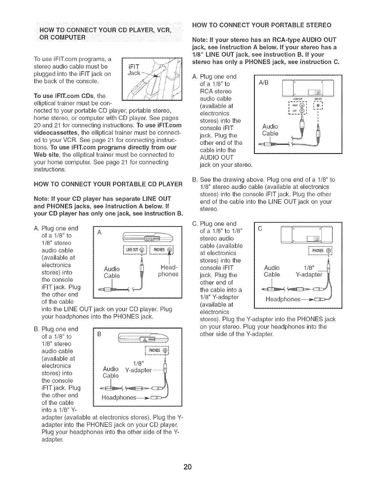
HOW TO CONNECT YOUR PORTABLE CD PLAYER
Note: If your CD ptayer has separate LINE OUT
and PHONES jacks, see instruction A below. If
your CD player has only one jack, see instruction B.
A, Plug one end
of a 1/8" to
1/8" stereo
audio cable
(available at
electronics
stores) into
the console
iFF jack, Plug
the other end
of the cable
into the LINE OUT jack on your CD player, Plug
your headphones into the PHONES jack,
A
i u,Eou,®i [..:!o!!!.¢i
............ _u--- T
Audio _ Head-
Cable phones
B, Plug one end
of a 1/8" to B
1/8" stereo
audio cable i PH0_ES@j
(available at
electronics
stores) into
the console
iFF jack, Plug
the other end
of the cable
into a 1/8" Yo
adapter (available at electronics stores), Plug the Y-
adapter into the PHONES jack on your CD player,
Plug your headphones into the other side of the Y-
adapter,
HOW TO CONNECT YOUR PORTABLE STEREO
Note: if your stereo has an RCA=type AUDIO OUT
jack, see instruction A below. If your stereo has a
1/8" LINE OUT jack, see instruction B. If your
stereo has only a PHONES jack, see instruction C.
A, Plug one end
of a 1/8" to
RCA stereo
audio cable
(available at
electronics
stores) into the
console iFF
jack, Plug the
other end of the
cable into the
AUDIO OUT
jack on your stereo,
AU_OOL¢ UNEOUT
...... ===U
...... @ ", ",,,
i LF? u
Audio __
Cable
B, See the drawing above, Plug one end of a 1/8" to
1/8" stereo audio cable (available at electronics
stores) into the console iFF jack, Plug the other
end of the cable into the LINE OUT jack on your
stereo,
C, Plug one end
of a 1/8" to 1/8" C [===]: :[==_
stereo audio _ [_
cable (available .................
at electronics i PHONES¢i
u
stores) into the
console iFF
jack, Plug the
other end of
the cable into a
1/8" Y-adapter
(available at
electronics
stores), Plug the Y-adapter into the PHONES jack
on your stereo, Plug your headphones into the
other side of the Y-adapter,
20
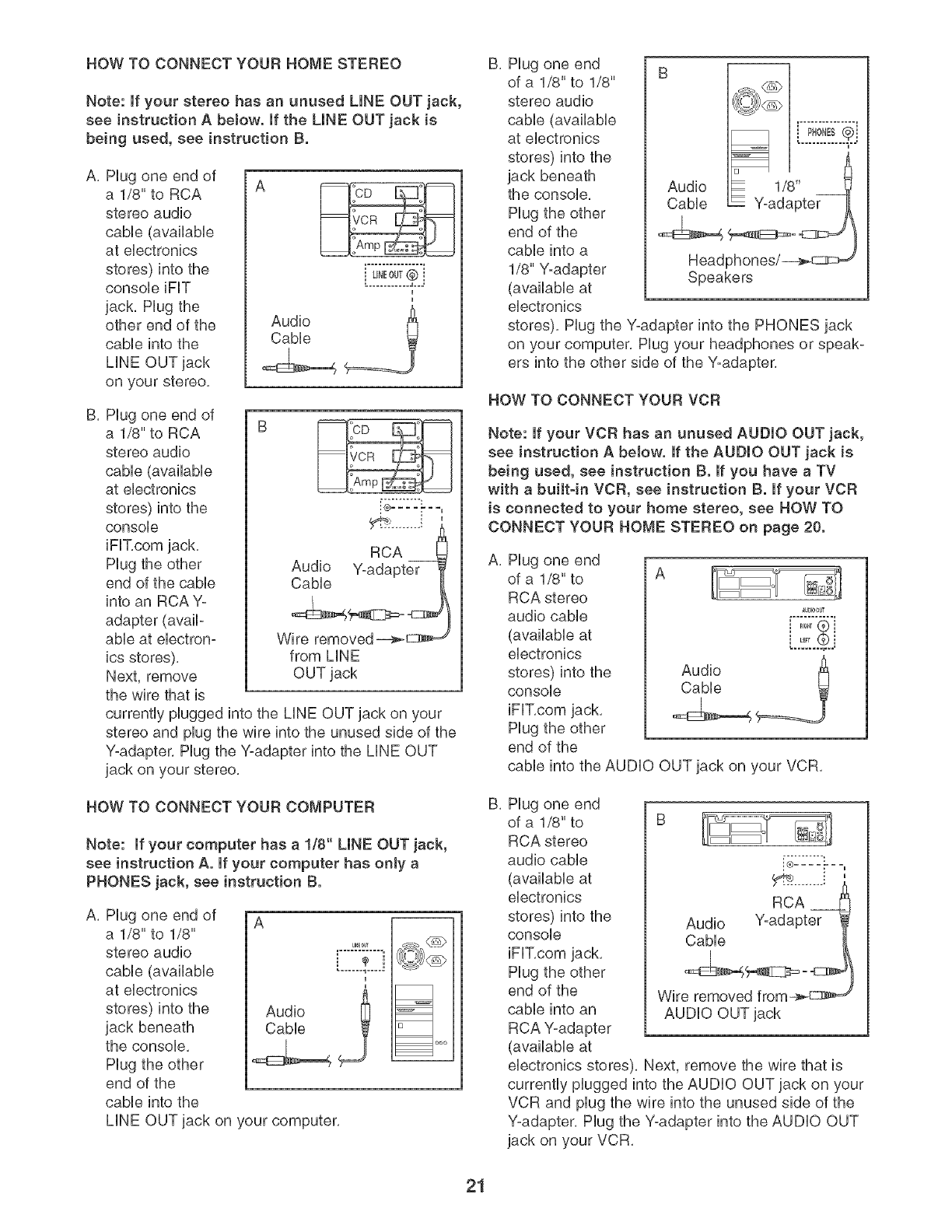
HOW TO CONNECT YOUR HOME STEREO
Note: if your stereo has an unused LINE OUT jack,
see instruction A below. If the UNE OUT jack is
being used, see instruction B.
A, Hug one end of
a 1/8" to RCA
stereo audio
cabb (availabb
at ebctronbs
stores) into the
consob iFIT
jack, Hug the
other end of the
cabb into the
LiNE OUT jack
on your stereo,
k2!o!!.£j
Audio ______=_
Cable
B. Hug one end of
a 1/8" to RCA
stereo audio
cable (available
at electronics
stores) into the
console
RCA
Audio Y-adapter
Cable
Hug the other
end of the cable
into an RCA Y-
adapter (avail-
able at electron- Wire removed _
ics stores), from LiNE
Next, remove OUT jack
the wire that is
currently plugged into the LiNE OUT jack on your
stereo and plug the wire into the unused side of the
Y-adapter. Hug the Y-adapter into the LiNE OUT
jack on your stereo.
HOW TO CONNECT YOUR COMPUTER
Note: If your computer has a 1/8" LINE OUT jack,
see instruction A. If your computer has only a
PHONES jack, see instruction B.
A. Hug one end of
a 1/8" to 1/8"
stereo audio
cable (available
at electronics
stores) into the
jack beneath
the console.
Hug the other
end of the
cable into the
A
I
Audio
Cable i
_1 uoo
LiNE OUT jack on your computer.
B, Hug one end
of a 1/8" to 1/8"
stereo audio
cable (available
at electronics
stores) into the
jack beneath
the console.
Hug the other
end of the
cable into a
1/8" Y-adapter Speakers
(available at
electronics
stores). Hug the yoadapter into the PHONES jack
on your computer. Hug your headphones or speak°
ers into the other side of the Y-adapter.
HOW TO CONNECT YOUR VCR
Note: if your VCR has an unused AUDIO OUT jack,
see instruction A below. If the AUDIO OUT jack is
being used, see instruction B. If you have a TV
with a built-in VOR, see instruction B. If your VOR
is connected to your home stereo, see HOW TO
CONNECT YOUR HOME STEREO on page 20.
A, Hug one end
of a 1/8" to A
RCA stereo
audio cable
(available at
electronics
stores) into the
console
iFIT,com jack,
Hug the other
end of the
cable into the AUDIO OUT jack on your VCR,
au_00t¢
.....® !
B, Hug one end
of a 1/8" to
RCA stereo
audio cable
(available at
electronics
stores) into the
console
iFIT.com jack.
Hug the other
end of the
cable into an
RCA Y-adapter
(available at
i® .......
RCA
Audio Y-adapter
Cable
Wire removed from_ d
AUDIO OUT jack
electronics stores). Next, remove the wire that is
currently plugged into the AUDIO OUT jack on your
VCR and plug the wire into the unused side of the
Y-adapter. Hug the Y-adapter into the AUDIO OUT
jack on your VCR.
21
EXERCISE GUiDELiNES
THE FOUR BAsmc TYPES OF WORKOUTS
Muscb Building
To increase the size and strength of your muscies,
push them chose to their maximum capacity, Your mus-
cles wHi continualiy adapt and grow as you progres-
siveiy increase the intensity of your exercise, You can
adjust the intensity ievei of an individuai exercise in
two ways:
by changing the amount of resistance used,
by changing the number of repetitions or sets per-
formed, (A "repetition" is one compiete cycie of an
exercise, such as one sit-up, A "set" is a series of
repetitions,)
The proper amount of resistance for each exercise
depends upon the individuai user, You must gauge
your Hmits and select the amount of resistance that is
right for you, Begin with 3 sets of 8 repetitions for each
exercise you perform, Rest for 3 minutes after each
set, When you can compHete 3 sets of 12 repetitions
without difficuity, increase the amount of resistance,
Toning
You can tone your muscles by pushing them to a mod-
erate percentage of their capacity, Select a moderate
amount of resistance and increase the number of rep-
etitions in each set. Complete as many sets of 15 to
20 repetitions as possible without discomfort, Rest for
1 minute after each set, Work your muscles by com-
pleting more sets rather than by using high amounts of
resistance,
Weight Loss
To Hoseweight, use a Howamount of resistance and
increase the number of repetitions in each set,
Exercise for 20 to 30 minutes, resting for a maximum
of 30 seconds between sets,
Cross Training
Cross training is an efficient way to get a compiete and
weli-balanced fitness program, An exampie of a bal-
anced program is:
Pian strength training workouts on Monday,
Wednesday, and Friday,
Pian 20 to 30 minutes of aerobic exercise, such as
running on a treadmili or riding an ellipticai exerciser
or exercise cycie, on Tuesday and Thursday,
, Rest from both strength training and aerobic exercise
for at bast one fuli day each week to give your body
time to regenerate,
The combination of strength training and aerobic exer-
cise wiii reshape and strengthen your body, plus devel-
op your heart and lungs,
PERSONALIZING YOUR EXERCISE PROGRAM
Determining the exact length of time for each workout,
as well as the number of repetitions or sets completed,
is an individual matter, it is important to avoid overdo-
ing it during the first few months of your exercise pro-
gram, You should progress at your own pace and be
sensitive to your body's signals, if you experience pain
or dizziness at any time while exercising, stop immedi-
ately and begin cooling down, Find out what is wrong
before continuing. Remember that adequate rest and a
proper diet are important factors in any exercise pro-
gram,
WARMING UP
Begin each workout with 5 to 10 minutes of stretching
and light exercise to warm up, Warming up prepares
your body for more strenuous exercise by increasing
circulation, raising your body temperature and deliver-
ing more oxygen to your muscles,
WORKING OUT
Each workout should include 6 to 10 different exercis-
es, Select exercises for every major muscle group,
emphasizing areas that you want to develop most, To
give balance and variety to your workouts, vary the
exercises from session to session,
Schedule your workouts for the time of day when your
energy level is the highest, Each workout should be
followed by at bast one day of rest, Once you find the
schedule that is right for you, stick with it,
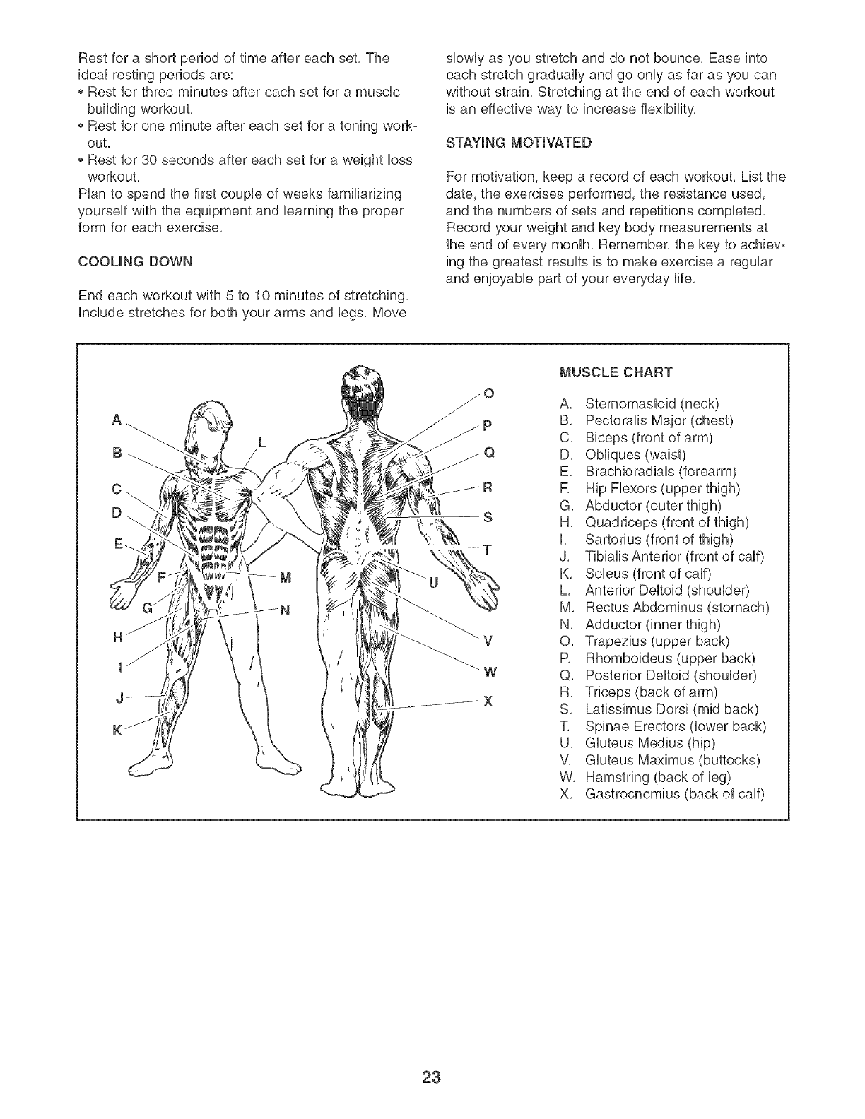
EXERCISE FORM
Maintaining proper form is an essential part of an
effective exercise program, This requires moving
through the full range of motion for each exercise, and
moving only the appropriate parts of the body,
Exercising in an uncontrolled manner will leave you
feeling exhausted, On the exercise guide accompany-
ing this manual you wiii find photographs showing the
correct form for several exercises, and a list of the
muscles affected, See the muscle chart on the next
page to find the names of the muscles,
The repetitions in each set should be performed
smoothly and without pausing, The exertion stage of
each repetition should last about half as long as the
return stage, Proper breathing is important, Exhale
during the exertion stage of each repetition and inhale
during the return stroke, Never hold your breath,
22
Rest for a short period of time after each set. The
ideaU resting periods are:
Rest for three minutes after each set for a muscle
building workout.
Rest for one minute after each set for a toning work-
out.
Rest for 30 seconds after each set for a weight bss
workout.
Han to spend the first coupb of weeks familiarizing
yourseUf with the equipment and barning the proper
form for each exercise.
COOLING DOWN
End each workout with 5 to 10 minutes of stretching.
include stretches for both your arms and bgs. Move
slowly as you stretch and do not bounce, Ease into
each stretch gradually and go only as far as you can
without strain, Stretching at the end of each workout
is an effective way to increase flexibility,
STAYING MOTIVATED
For motivation, keep a record of each workout. List the
date, the exercises performed, the resistance used,
and the numbers of sets and repetitions completed.
Record your weight and key body measurements at
the end of every month. Remember, the key to achievo
ing the greatest results is to make exercise a regular
and enjoyable part of your everyday life.
R
S
T
_V
W
X
MUSCLE CHART
A. Sternomastoid (neck)
B. Pectoralis Major (chest)
C. Biceps (front of arm)
D. Obliques (waist)
E. Brachioradials (forearm)
R Hip Flexors (upper thigh)
G. Abductor (outer thigh)
H. Quadriceps (front of thigh)
I. Sartorius (front of thigh)
J. Tibialis Anterior (front of calf)
K. Soleus (front of calf)
L. Anterior Deltoid (shoulder)
M. RectusAbdominus (stomach)
N. Adductor (inner thigh)
O. Trapezius (upper back)
P. Rhomboideus (upper back)
Q. Posterior Deltoid (shoulder)
R. Triceps (back of arm)
S. Latissimus Dorsi (mid back)
T. Spinae Erectors (lower back)
U. Gluteus Medius (hip)
V. Gluteus Maximus (buttocks)
W. Hamstring (back of leg)
X. Gastrocnemius (back of calf)
23

PART iDENTiFiCATiON CHART
See the drawings beUowto identify small parts used in assemMy, The number in parentheses by each drawing is
the key number of the part, from the PART LUSTin the center of this manual, Note: Some small parts may
have been pre-attached for shipping purposes, If you cannot find a part in the parts bag, check to see if
it has been pre-attached, If a part is missing, call totFfree 1-877-992-5999,
B
M8 Large Zinc Washer (74)
MIO Large Zinc/BUack
Washer (82,186)
i,
j J
M8 Split Washer (140)
M4 x 5ram Screw (131)
M8 NyUonLocknut (102)
MIO NyUon Locknut (81)
MIO Split Washer (114)
\,
M8 Washer (139)
M10 x 25mm Patch Screw (135)
MIO x 25mm Button Screw (87)
M8 x 38mm Button BoUt(103)
M8 x 40mm Button Screw (142)
M8 x 51ram Button Screw (98)
MIO x 54mm Button Bolt (90)
M4 x 16mm Screw (85)
M6 x 16mm Screw (130)
MIO x 75mm Patch Screw (99)
MIO x 75mm Button Bolt (129)
M8 x 19mm Button Screw (94)
MIO x 25mm Screw (86)
MIO x 78mm Button Screw (101)
MIO x 78mm Carriage Bolt (149_ _

PART LiST--Model No. 831.159950 Rt204A
Key No. Qty. Description Key No. Qty. Description
1 1 Upright Base
2 1 Seat Base
3 1 Upright
4 1 Leg Lever
5 1 Left Rail
6 1 Right Rail
7 1 Left PedaU Leg
8 1 Right PedaU Leg
9 1 Seat Stabilizer
10 1 Upright Stabilizer
11 1 Top Arm
12 1
13 1 Left Arm
14 1 Leg Lever Bracket
15 1 Mech Frame
16 1 Right HandUe
17 1 Left HandUe
18 1 Large BeUtPulley
19 1 FUyWheeU
20 1 Left Mech Cover
21 1 Right Mech Cover
22 1 Backrest
23 1 Seat
24 1 "C'°magnet
25 1 Right Side ShieUd
26 1 Left Side ShieUd
27 1 Left PedaU
28 1 Right PedaU
29 2 BeUtPulley Cover
30 2 Disk Cap
31 1 Crank
32 1 UdUer
33 1 Return Spring
34 1 Guide Rod
35 1 Resistance CaMe
36 1 Bushing Bracket
37 1 MiddUeWire Harness
38 1 Leg Lever Bumper
39 2 Leg Lever Bushing
40 2 19mm Round UnnerCap
41 1 38mm x 50mm Unner Cap
42 2 Top Arm Cap
43 2 PedaUWheeU
44 1 Base Knob
45 1 Left Rail Cap
46 2 Seat Stabilizer Cap
47 2 Stabilizer Wheel
48 4 Foot
49 1 Left Base Bushing
50 8 Swivel Bearing
51 5 1 3/4" Pulley
52 4 "V"-pulley
53 2 Resistance Band
54 2 Pulse Sensor/Wire
55 7
56 2
57 2
58 4
59 1
60 3
61 2
62 1
63 1
64 2
65 10
66 2
67 2
68 2
69 1
7O 4
71 1
72 2
73 1
74 2
75 2
76 1
77 1
78 2
79 1
80 2
81 13
82 8
83 14
84 2
85 32
86 8
87 2
88 1
89 2
90 6
91 1
92 6
93 4
94 2
95 6
96 2
97 1
98 4
99 2
100 6
101 2
102 7
103 6
104 2
105 2
106 3
107 1
108 3
3 1/2" Pulley
Band Wheel
Flange Spacer
Swivel Arm
Rep Counter
Limit Switch
Mech Arm Plate
Bungee Cord
Resistance Motor
Foam Pad
Small Base Wheel
Disk Hub
Double Locknut
Crank Shaft
System Wire Harness
M6 x 12mm Flat Head Screw
Console
M8 x 51mm Bolt Set
Right Rail Cap
M8 Large Zinc Washer
Arm Cap
Mech Arm
Motor Assm,
MIO x 30mm Button Screw
Lower Pulley Plate
2 3/4" Pulley
MIO Nylon Locknut
MIO Large Zinc Washer
Wheel Snap Ring
Flange Screw
M4 x 16mm Screw
MIO x 25mm Screw
MIO x 25mm Button Screw
MIO x 89mm Button Bolt
MIO x 49mm Button Bolt
MIO x 54mm Button Bolt
MIO x 48mm Button Bolt
M3 x 19mm Screw
M5 x 16mm Screw
M8 x 19mm Button Screw
Pedal Leg Bearing
33mm Spacer
Right Base Bushing
M8 x 51mm Button Screw
MIO x 75mm Patch Screw
M3 Nut
MIO x 78mm Button Screw
M8 Nylon Locknut
M8 x 36mm Button Bolt
M6 x 16mm Flat Head Screw
Pulley Housing
16mm Spacer
Upper Pulley Plate
M5 Nut

KeyNo. Qty. Description KeyNo. Qty. Description
109 4 ShortWheelAxb 155 2 CrankSnapRing
110 4 WheelBearing 156 1 FlywheelSnapRing
111 2 98mmSpacer 157 6 CabbClip
112 3 51mmSpacer 158 1 AnHeStrap
113 3 LongWheelAxb 159 2 WireHarness
114 4 MIOSplitWasher 160 2 HandStrap
115 1 PushLink 161 6 MIOWasher
116 2 Spring 162 1 Rope
117 2 M4x 25ramScrew 163 2 ShortCable
118 2 PulleyStrap 164 2 LongCable
119 4 M4x 12ramScrew 165 1 Transformer
120 1 PowerPlugqn 166 1 M4x 35ramScrew
121 1 MIOx 58ramButtonBolt 167 4 FingerGuard
122 1 MIOx 32ramButtonBolt 168 9 MIOJamNut
123 2 13ramSpacer 169 1 M4NylonLocknut
124 1 76ramSpacer 170 1 ReedSensor
125 4 M8x 15ramScrew 171 2 M6x 25ramScrew
126 2 Clamp 172 2 15ramSpacer
127 8 M6NylonLocknuts 173 1 11ramSpacer
128 4 M5NylonLoeknut 174 1 ExtendedHubPulley
129 1 MIOx 75ramButtonBolt 175 2 ExtensionStrap
130 8 M6x 16ramScrew 176 2 PlasticWasher
131 4 M4x 5ramScrew 177 2 MIOSplitZincWasher
132 2 M6x 90ramBolt 178 1 PulleyZincWasher
133 2 M6x 112mmBolt 179 2 M5x 20ramScrew
134 1 MIOx 116mmButtonBolt 180 2 PlasticSpacer
135 6 MIOx 25ramPatchScrew 181 1 ReedSwitchHate
136 4 MIOx 112mmButtonBolt 182 4 M5Washer
137 2 M4x 7ramScrew 183 2 ShortHandgrip
138 2 MIOx 16ramButtonScrew 184 2 LongHandgrip
139 6 M8W/asher 185 1 Belt
140 6 M8SplitWasher 186 6 MIOLargeBlackWasher
141 4 PedalLegBushing 187 1 SensorWireHarness
142 2 M8x 40ramButtonScrew 188 1 UpperWireHarness
143 4 M6x 29mmFiatHeadScrew 189 1 MIOx 83mmBoltSet
144 1 M8x 37mmButtonScrew 190 1 98mmLargeSpacer
145 1 ReedSwitch 191 2 RopeCover
146 1 Magnet 192 1 Link
147 4 M6x lOmmButtonScrew 193 1 LowerClamp
148 1 M8x 58mmButtonScrew 194 1 UpperClamp
149 2 MIOx 78mmCarriageBolt 195 2 M5x 21mmFiatHeadScrew
150 1 M6x 35mmBolt # 1 User'sManual
151 2 M6Nut # 1 ExerciseGuide
152 1 LowerWireHarness # 1 ExerciseVideo
153 4 8ramSpacer # 2 AllenWrench
154 2 UprightStabilizerCap
Note:"#"indicatesa non-illustratedpart,Specificationsaresubjectto changewithoutnotice,Seethebackcover
ofthismanualforinformationaboutorderingreplacementparts,if apartismissing,calltoll-free
1-888-533-1333,
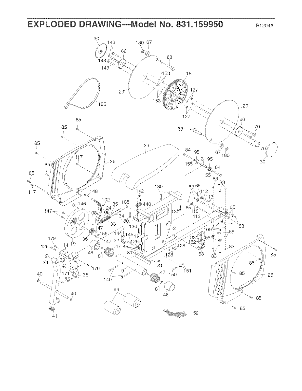
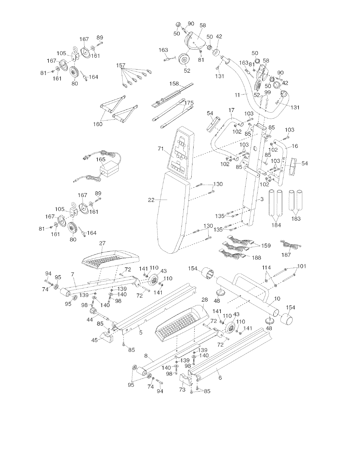
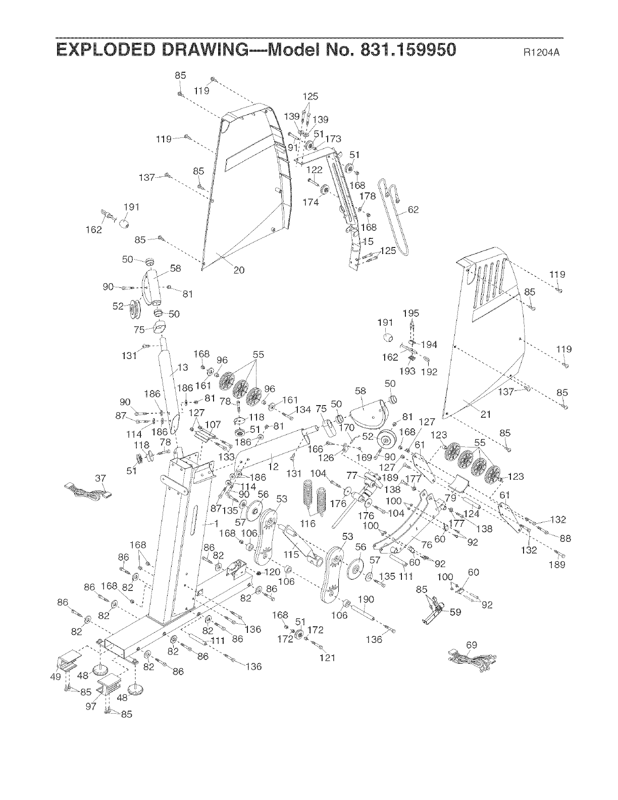
EXPLODED DRAWING--Model No. 831.159950 m2o4A
3O
\
143
143
A
143
66
180 67
\\
@
68
I
153 18
127
153
85
142
23 _ ..........
/
68
70
39
4O
179
//
/ /
41
40
149
64
65
85
25
1
81
105
/
161
1 67 89
,161
-164
80
160
157
163
;@. j90 58
5O 50 42
//
I
81
52 d't
131
158
54
\
5O
58
9O
/
\\\
17 \
i 103 y_ /
102
31
103
105.
167 89
J102
/85
Jl 6
//
81 161
94 95
/
7_43
_11o
114 01
95 28 _10
154
85
\
85
8\
48
95 ,/
74 914
EXPLODED DRAWING--Model No. 831.159950 m2o4A
191 174
173
51
162
2O
82
37
131
118
5t
168 /
168 55
96
126
58
1
53
/56
i
57 _€
35 111
136
%,
121
195
191
i/
162
193 192
5O
85
92
69

Your Home
For repair - in your home - of all major brand appliances, lawn and garden equipment,
or heating and cooling systems, no matter who made it, no matter who sold it!
For the replacement parts, accessories, and user's manuals that you need to do-it-yourself.
For Sears professional installation of home appliances
and items like garage door openers and water heaters.
1-800-4-MY-HOM E<_
(1-800-469-4663)
www.sears.com
Anytime, day or night
(U.S.A. and Canada)
www.sears.ca
Our Home
For repair of carry-in products like vacuums, lawn equipment,
and electronics, call or go on-line for the location of your nearest
Sears Parts and Repair Center.
1-800-488-1222 Anytime, day or night (U.S.A. only)
www.sears.com
To purchase a protection agreement (U.S.A.)
or maintenance agreement (Canada) on a product serviced by Sears:
1-800-827-6655 (U.S.A.) 1-800-361-6665 (Canada)
Para pedir servicio de reparacion a domicilio, y para ordenar piezas:
1-888-SU-HOGAR SM (1-888-784-6427)
/
f
@ Registered Trademark /_M Trademark /SMService Mark of Sears, Roebuck and Co.
® Marca Registrada /TMMarca de F_.brica /SMMarca de Servicio de Sears, Roebuck and Co.
FULL 90-DAY WARRANTY
f
For 90 days from the date of purchase, if failure occurs due to defect in materiai or workmanship in this
ELLiPTiCAL TRAINER EXERCISER, contact the nearest Sears Service Center throughout the United
States and Sears wHi repair or repiace the ELLiPTiCAL TRAINER EXERCISER, free of charge,
This warranty does not appiy when the ELLiPTiCAL TRAINER EXERCISER is used commercialiy or for
rentai purposes,
This warranty gives you specific legal rights, and you may also have other rights which vary from state
to state,
Sears, Roebuck and Co., Dept 8!7WA, Hoffman Estates, IL {}0!79
J
J
Part No, 217383 R1204A Printed in China @2004 iCON IP, Inc,
