Proform 831246330 User Manual PRO FORM CROSSWALK 405E Manuals And Guides L0609455
PROFORM Treadmill Manual L0609455 PROFORM Treadmill Owner's Manual, PROFORM Treadmill installation guides
User Manual: Proform 831246330 831246330 PROFORM PRO-FORM CROSSWALK 405E - Manuals and Guides View the owners manual for your PROFORM PRO-FORM CROSSWALK 405E #831246330. Home:Fitness Equipment Parts:Proform Parts:Proform PRO-FORM CROSSWALK 405E Manual
Open the PDF directly: View PDF ![]() .
.
Page Count: 28
ModeJNo.831.24633.0
SeriaJ No.
Seri_
Number
Decal
, Assembly
,Operation
,, Maintenance
,Part List and Drawing
TR LL EXERCIS
User's Manual
Sears, Roebuck and Co., Hoffman Estates, IL 60179
TABLE OF CONTENTS
iMPORTANT PRECAUTIONS ................................................................ 3
BEFORE YOU BEGIN ...................................................................... 5
ASSEMBLY ............................................................................... 6
OPERATION AND ADJUSTMENT ............................................................ 10
HOW TO FOLD AND MOVE THE TREADMILL .................................................. 16
TROUBLESHOOTING ..................................................................... 18
CONDiTiONiNG GUiDELiNES ............................................................... 20
PART LiST .............................................................................. 23
EXPLODED DRAWING .................................................................... 24
ORDERING REPLACEMENT PARTS .................................................. Back Cover
WARRANTY ...................................................................... Back Cover
iMPORTANT PRECAUTIONS

The decals shown below have been placed on the treadmill, if adecal is missing,
or if it is not legible, call toll=free 1-888-533-1333 and order afree replacement
decal. Apply the decal in the location shown. Note: The decals are not shown at
actual size.
Protect yourself end
others from risk of serious
injury. Reed the user's
manual end :
.Stand only on the
side rails when
starting or stopping
treadmill.
,Change speed in
small increments.
'Hold handrails to
prevent fallil_g, and
always wear the
safety clip while
operating treadmill.
,Stop if you feel faint,
dizzy, or short of
breath.
, Fully engage storage
latch before tread-
mill is moved o_
sto!ed.
•Reduce incline to ts
lowest level befole
fold ng treadmill into
storage position.
.Never allow
children on or
around treadmill.
,Remove key when
_o_ in use.
.Keep clothing,
fingers, and hair
away from moving
belt.
.Never try to adjust
or fix the belt while
it is moving.
-Always weal
athletic shoes while
operating treadmill.
4
BEFORE YOU BEGIN
Thank you for selecting the new PROFORM ®CROSS-
WALK 405E treadmill. The CROSSWALK 405E tread-
mill offers a selection of features designed to make your
workouts at home more effective and enjoyable. And
when you're not exercising, the CROSSWALK 405E
treadmill can be folded up, requiring less than half the
floor space of other treadmills.
For your benefit, read this manual carefully before
using the treadmill. If you have questions after read-
ing this manual, call 1-800-4-MY-HOME ®(1-800-469-
4663).To help us assist you, please note the product
model number and serial number before calling. The
model number of the treadmill is 831.24633.0. The ser-
ial number can be found on a decal attached to the
treadmill (see the front cover of this manual for the lo-
cation).
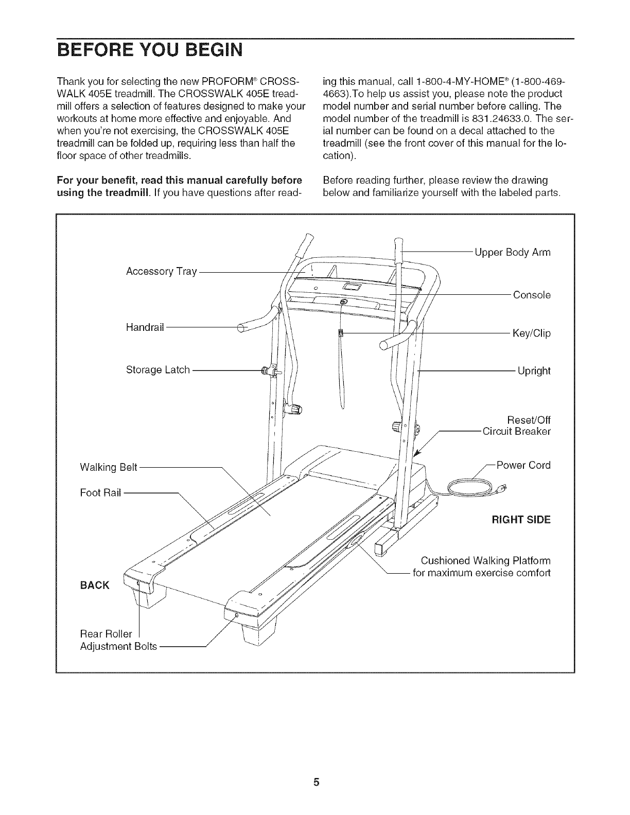
Before reading further, please review the drawing
below and familiarize yourself with the labeled parts.
Accessory Tray
Handrail
Storage Latch
Upper Body Arm
Console
Key/Clip
Upright
Reset/Off
Circuit Breaker
Walking Belt
Foot Rail
RIGHT SiDE
BACK
Cushioned Walking Platform
-- for maximum exercise comfort
Rear Roller
Adjustment Bolts
ASSEMBLY
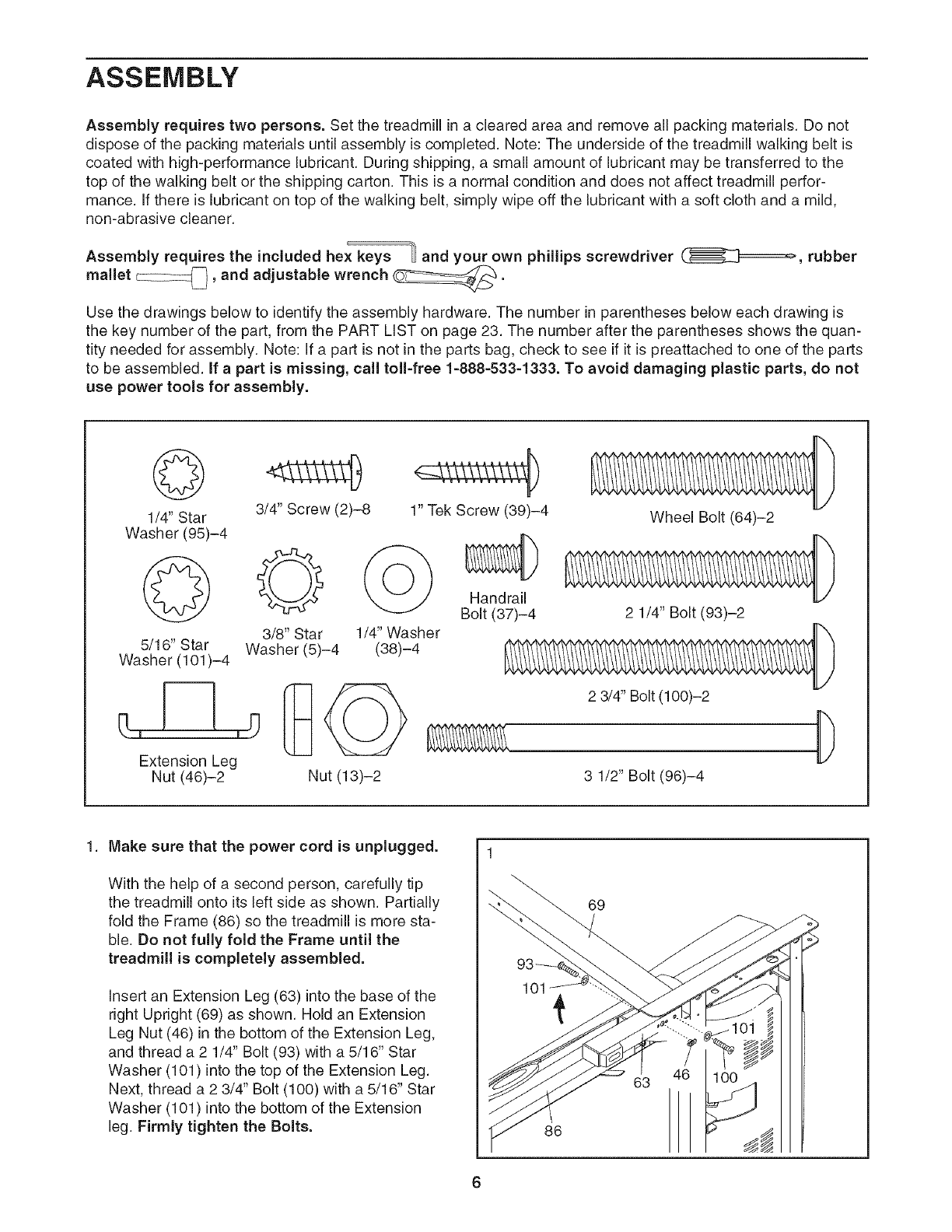
Assembly requires two persons. Set the treadmill in a cleared area and remove all packing materials. Do not
dispose of the packing materials until assembly is completed. Note: The underside of the treadmill walking belt is
coated with high-performance lubricant. During shipping, a small amount of lubricant may be transferred to the
top of the walking belt or the shipping carton. This is a normal condition and does not affect treadmill perfor-
mance. If there is lubricant on top of the walking belt, simply wipe off the lubricant with a soft cloth and a mild,
non-abrasive cleaner.
Assembly requires the included hex keys _ and your own phillips screwdriver (_======_, rubber
mallet c::::z::_, and adjustable wrench _.
Use the drawings below to identify the assembly hardware. The number in parentheses below each drawing is
the key number of the part, from the PART LIST on page 23. The number after the parentheses shows the quan-
tity needed for assembly. Note: If a part is not in the parts bag, check to see if it is preattached to one of the parts
to be assembled, if apart is missing, call toll-free 1-888-533-1333. To avoid damaging plastic parts, do not
use power tools for assembly.
3/4" Screw (2)-8
1/4" Star
Washer (95)-4
5/16" Star Washer (5)-4
Washer (101 )-4
Extension Leg
Nut (46)-2 Nut (13)-2
1" Tek Screw (39)-4
(_ Handrai_
Bolt (37)-4
3/8" Star 1/4" Washer
(38)-4
Wheel Bolt (64)-2
2 1/4" Bolt (93)-2
2 3/4" Bolt (100)-2
,D
3 1/2" Bolt (96)-4
1. Make sure that the power cord is unplugged.
With the help of a second person, carefully tip
the treadmill onto its left side as shown. Partially
fold the Frame (86) so the treadmill is more sta-
ble. Do not fully fold the Frame until the
treadmill is completely assembled.
Insert an Extension Leg (63) into the base of the
right Upright (69) as shown. Hold an Extension
Leg Nut (46) in the bottom of the Extension Leg,
and thread a 2 1/4" Bolt (93) with a 5/16" Star
Washer (101) into the top of the Extension Leg.
Next, thread a 2 3/4" Bolt (100) with a 5/16" Star
Washer (101) into the bottom of the Extension
leg. Firmly tighten the Bolts.
101
69
86
46
63
2. 2
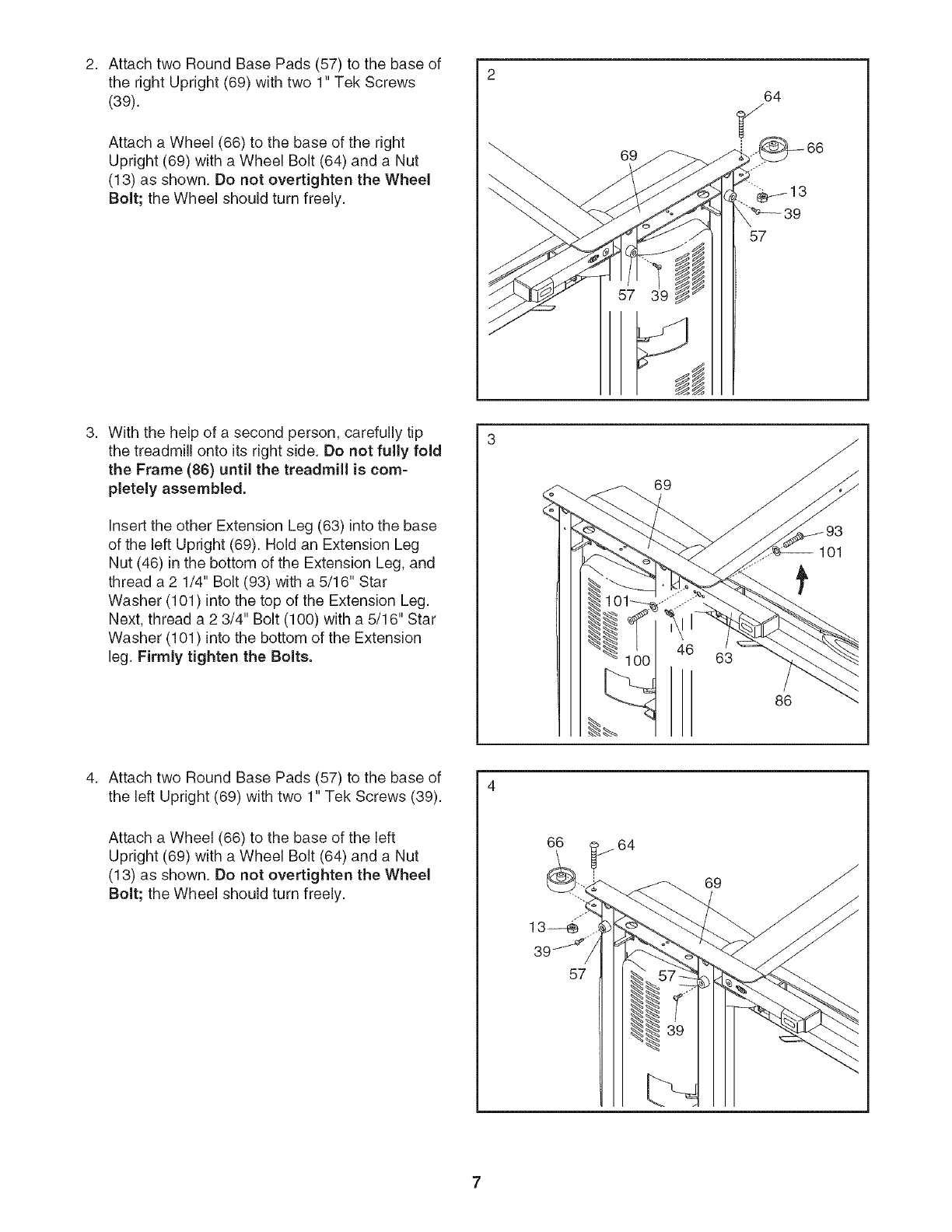
AttachtwoRoundBasePads(57)tothebaseof
therightUpright(69)withtwo1"TekScrews
(39).
Attacha Wheel(66)tothebaseoftheright
Upright(69)witha WheelBolt(64)anda Nut
(13)asshown.DonotovertightentheWheel
Bolt;theWheelshouldturnfreely.
69
64
Withthehelpofa secondperson,carefullytip
thetreadmillontoitsrightside.Donotfullyfold
theFrame(86) until the treadmill is com-
pletely assembled.
Insert the other Extension Leg (63) into the base
of the left Upright (69). Hold an Extension Leg
Nut (46) in the bottom of the Extension Leg, and
thread a 2 1/4" Bolt (93) with a 5/16" Star
Washer (101) into the top of the Extension Leg.
Next, thread a 2 3/4" Bolt (100) with a 5/16" Star
Washer (101) into the bottom of the Extension
leg. Firmly tighten the Bolts.
69
46 63
86
101
Attach two Round Base Pads (57) to the base of
the left Upright (69) with two 1" Tek Screws (39).
Attach a Wheel (66) to the base of the left
Upright (69) with a Wheel Bolt (64) and a Nut
(13) as shown. Do not overtighten the Wheel
Bolt; the Wheel should turn freely.
57
69
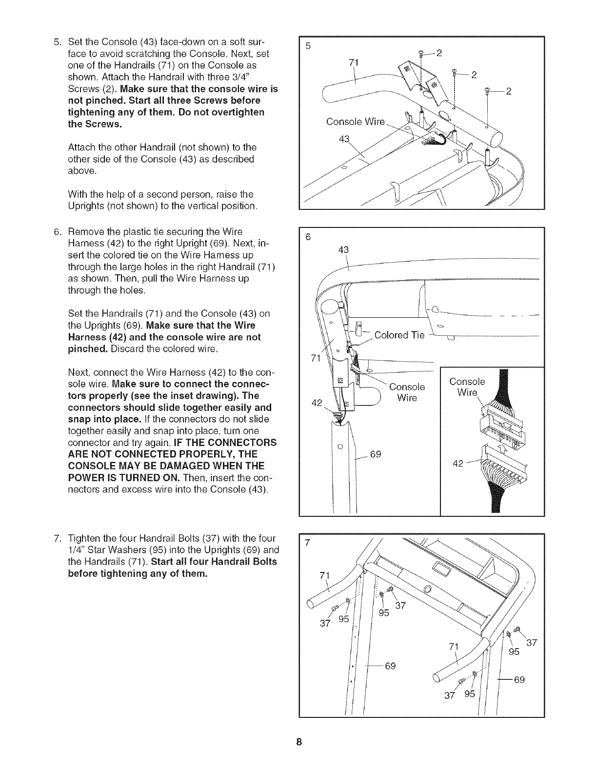
SettheConsole(43)face-downona softsur-
facetoavoidscratchingtheConsole.Next,set
oneof theHandrails(71)ontheConsoleas
shown.AttachtheHandrailwiththree3/4"
Screws(2).Makesurethattheconsole wire is
not pinched. Start all three Screws before
tightening any of them. Do not overtighten
the Screws.
Attach the other Handrail (not shown) to the
other side of the Console (43) as described
above.
With the help of a second person, raise the
Uprights (not shown) to the vertical position.
Remove the plastic tie securing the Wire
Harness (42) to the right Upright (69). Next, in-
sert the colored tie on the Wire Harness up
through the large holes in the right Handrail (71)
as shown. Then, pull the Wire Harness up
through the holes.
Set the Handrails (71) and the Console (43) on
the Uprights (69). Make sure that the Wire
Harness (42) and the console wire are not
pinched. Discard the colored wire.
Next, connect the Wire Harness (42) to the con-
sole wire. Make sure to connect the connec-
tors properly (see the inset drawing). The
connectors should slide together easily and
snap into place. If the connectors do not slide
together easily and snap into place, turn one
connector and try again. IF THE CONNECTORS
ARE NOT CONNECTED PROPERLY, THE
CONSOLE MAY BE DAMAGED WHEN THE
POWER IS TURNED ON. Then, insert the con-
nectors and excess wire into the Console (43).
6
43
i
Colored Tie
W ire
=
Console
Wire
42
Tighten the four Handrail Bolts (37) with the four
1/4" Star Washers (95) into the Uprights (69) and
the Handrails (71). Start all four Handrail Bolts
before tightening any of them. 71
37
37
95
8
8. 8
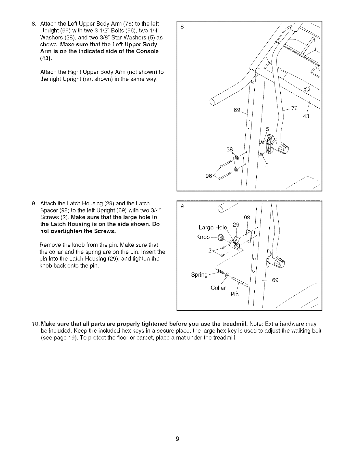
Attach the Left Upper Body Arm (76) to the left
Upright (69) with two 3 1/2" Bolts (96), two 1/4"
Washers (38), and two 3/8" Star Washers (5) as
shown. Make sure that the Left Upper Body
Arm is on the indicated side of the Console
(43).
Attach the Right Upper Body Arm (not shown) to
the right Upright (not shown) in the same way.
38
43
Attach the Latch Housing (29) and the Latch
Spacer (98) to the left Upright (69) with two 3/4"
Screws (2). Make sure that the large hole in
the Latch Housing is on the side shown. Do
not overtighten the Screws.
Remove the knob from the pin. Make sure that
the collar and the spring are on the pin. Insert the
pin into the Latch Housing (29), and tighten the
knob back onto the pin.
9
Large Hole
/
Spring
Collar Pin
98
10. Make sure that all parts are properly tightened before you use the treadmill. Note: Extra hardware may
be included. Keep the included hex keys in a secure place; the large hex key is used to adjust the walking belt
(see page 19). To protect the floor or carpet, place a mat under the treadmill.
OPERATION AND ADJUSTMENT
THE PRE-LUBRICATED WALKING BELT
Your treadmill features a walking belt coated with high-
performance lubricant, iMPORTANT: Never apply sil-
icone spray or other substances to the walking
belt or the walking platform. Such substances will
deteriorate the walking belt and cause excessive
wear.
HOW TO PLUG IN THE POWER CORD
tric shock. This product is equipped with a cord having
an equipment-grounding conductor and a grounding
plug. Plug the power cord into a surge suppressor,
and plug the surge suppressor into an appropriate
outlet that is properly installed and grounded in
accordance with all local codes and ordinances.
Important: The treadmill is not compatible with
GFCl-equipped outlets.
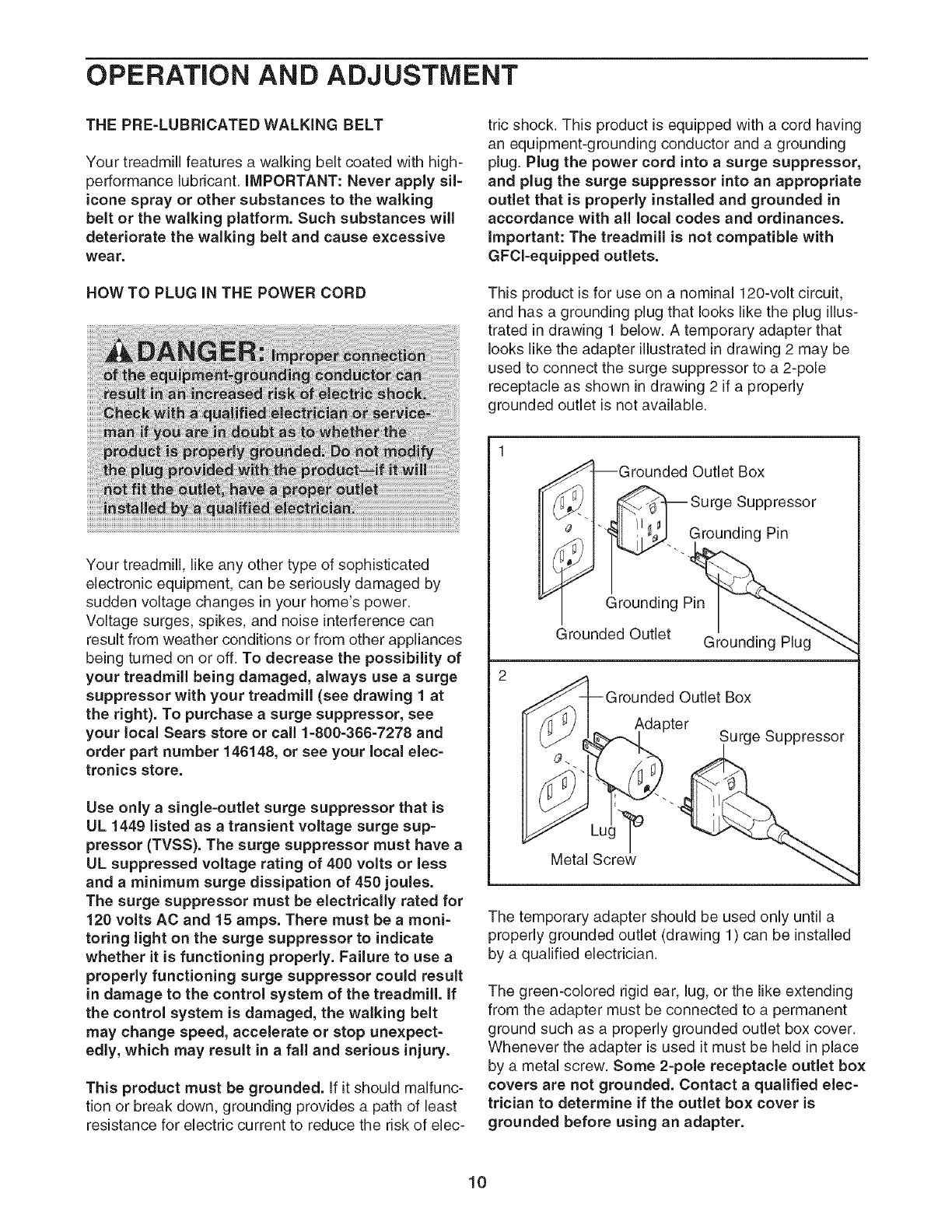
This product is for use on a nominal 120-volt circuit,
and has a grounding plug that looks like the plug illus-
trated in drawing 1 below. A temporary adapter that
looks like the adapter illustrated in drawing 2 may be
used to connect the surge suppressor to a 2-pole
receptacle as shown in drawing 2 if a properly
grounded outlet is not available.
Your treadmill, like any other type of sophisticated
electronic equipment, can be seriously damaged by
sudden voltage changes in your home's power.
Voltage surges, spikes, and noise interference can
result from weather conditions or from other appliances
being turned on or off. To decrease the possibility of
your treadmill being damaged, always use a surge
suppressor with your treadmill (see drawing 1 at
the right). To purchase asurge suppressor, see
your local Sears store or call 1-800-366-7278 and
order part number 146148, or see your local elec-
tronics store.
Use only a single-outlet surge suppressor that is
UL 1449 listed as a transient voltage surge sup-
pressor (TVSS). The surge suppressor must have a
UL suppressed voltage rating of 400 volts or less
and a minimum surge dissipation of 450 joules.
The surge suppressor must be electrically rated for
120 volts AC and 15 amps. There must be amoni-
toring light on the surge suppressor to indicate
whether it is functioning properly. Failure to use a
properly functioning surge suppressor could result
in damage to the control system of the treadmill, if
the control system is damaged, the walking belt
may change speed, accelerate or stop unexpect-
edly, which may result in a fall and serious injury.
This product must be grounded. If it should malfunc-
tion or break down, grounding provides a path of least
resistance for electric current to reduce the risk of elec-
I_]_Grounded Outlet Box
ur0oSu00ro or
_ _..GroundingPin
Grounding P_
_rounded Outlet Grounding Plug"_
2
_rounded Outlet Box
Adapter Surge Suppressor
The temporary adapter should be used only until a
properly grounded outlet (drawing 1) can be installed
by a qualified electrician.
The green-colored rigid ear, lug, or the like extending
from the adapter must be connected to a permanent
ground such as a properly grounded outlet box cover.
Whenever the adapter is used it must be held in place
by a metal screw. Some 2-pole receptacle outlet box
covers are not grounded. Contact a qualified elec-
trician to determine if the outlet box cover is
grounded before using an adapter.
10

CONSOLEDIAGRAM
........ £SB _ .........................................
_E_ EOT f
INCLIN E .................................................................................................................. SPEED t_a _'i _ _tu_ _ I1_ _i_"?__1be"_ e f°lO '__
123456789!40
Pulse ......................................................................................................................
Son or[[ .............................._lJ
oto:,, Co,LZt,c
on the console, remove the plastic.
FEATURES OFTHECONSOLE
The treadmill console offers a selection of features
designed to make your workouts more effective.
During each workout, you can change the speed and
incline of the treadmill with the touch of a button. As
you exercise, the console will display continuous exer-
cise feedback; you can even measure your heart rate
using the built-in pulse sensor.
Calorie Goal Programs
As you walk or run on the treadmill, the console will dis-
play the approximate number of calories you have
burned. If desired, you can set a goal to burn either 250
or 350 calories in a 30-minute workout, and the console
will count the calories you burn until you reach your
goal.
To use the manual mode of the console, follow the
steps beginning on page 12. To use a calorie goal
program, see page 13.
HOW TO TURN ON THE POWER
Plug in the power cord (see
page 10). Next, locate the
reset/off circuit breaker on
the treadmill frame near the
power cord. Make sure that
the circuit breaker is in the
"reset" position.
Reset
Next, stand on the foot rails of the treadmill. Locate the
clip attached to the key (see the drawing above), and
slide the clip securely onto the waistband of your
clothes. Then, insert the key into the console. After a
moment, the displays will light. Important: In an emer-
gency situation, the key can be pulled from the
console, causing the walking belt to slow to a stop.
Test the clip by carefully taking a few steps back-
ward; if the key is not pulled from the console, ad-
just the position of the clip.
Note: To prevent damage to the walking platform,
always wear clean shoes while using the treadmill.
11
HOWTO USETHE MANUALMODE
insert the key into the console.
See HOW TO TURN ON THE POWER on page
11.
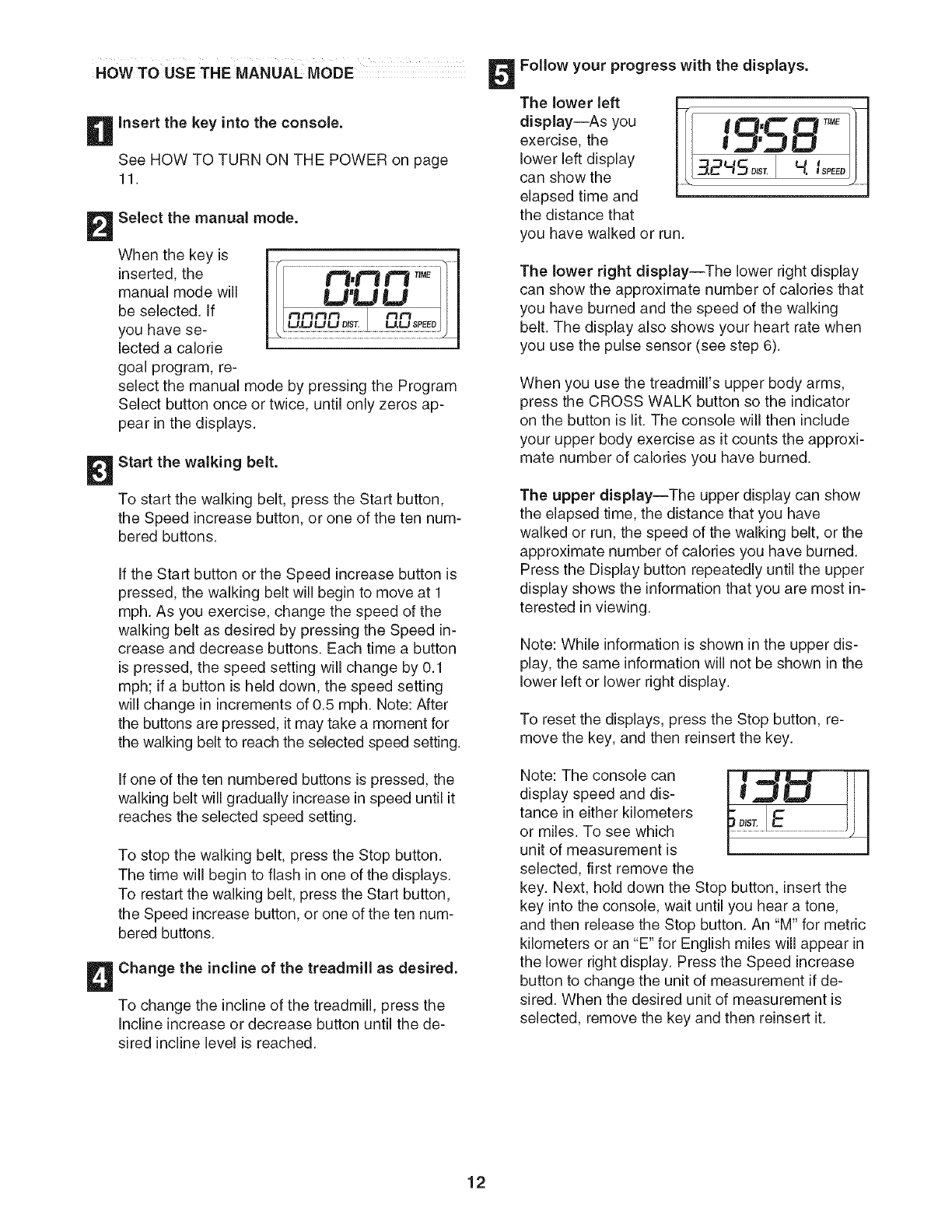
Select the manual mode.
When the key is
inserted, the
manual mode will
be selected. If
you have se-
lected a calorie
goal program, re-
j
select the manual mode by pressing the Program
Select button once or twice, until only zeros ap-
pear in the displays.
Start the walking belt.
To start the walking belt, press the Start button,
the Speed increase button, or one of the ten num-
bered buttons.
If the Start button or the Speed increase button is
pressed, the walking belt will begin to move at 1
mph. As you exercise, change the speed of the
walking belt as desired by pressing the Speed in-
crease and decrease buttons. Each time a button
is pressed, the speed setting will change by 0.1
mph; if a button is held down, the speed setting
will change in increments of 0.5 mph. Note: After
the buttons are pressed, it may take a moment for
the walking belt to reach the selected speed setting.
If one of the ten numbered buttons is pressed, the
walking belt will gradually increase in speed until it
reaches the selected speed setting.
To stop the walking belt, press the Stop button.
The time will begin to flash in one of the displays.
To restart the walking belt, press the Start button,
the Speed increase button, or one of the ten num-
bered buttons.
Change the incline of the treadmill as desired.
To change the incline of the treadmill, press the
Incline increase or decrease button until the de-
sired incline level is reached.
Follow your progress with the displays.
The lower left
display--As you
exercise, the
lower left display
can show the
elapsed time and
the distance that
you have walked or run.
The lower right display--The lower right display
can show the approximate number of calories that
you have burned and the speed of the walking
belt. The display also shows your heart rate when
you use the pulse sensor (see step 6).
When you use the treadmill's upper body arms,
press the CROSS WALK button so the indicator
on the button is lit. The console will then include
your upper body exercise as it counts the approxi-
mate number of calories you have burned.
The upper display--The upper display can show
the elapsed time, the distance that you have
walked or run, the speed of the walking belt, or the
approximate number of calories you have burned.
Press the Display button repeatedly until the upper
display shows the information that you are most in-
terested in viewing.
Note: While information is shown in the upper dis-
play, the same information will not be shown in the
lower left or lower right display.
To reset the displays, press the Stop button, re-
move the key, and then reinsert the key.
Note: The console can
display speed and dis-
tance in either kilometers
or miles. To see which
unit of measurement is
selected, first remove the
key. Next, hold down the Stop button, insert the
key into the console, wait until you hear a tone,
and then release the Stop button. An "M" for metric
kilometers or an "E" for English miles will appear in
the lower right display. Press the Speed increase
button to change the unit of measurement if de-
sired. When the desired unit of measurement is
selected, remove the key and then reinsert it.
12
Measure your heart rate if desired.
To measure your heart rate, stand on the foot
rails and place your left thumb on the pulse sen-
sor (see the drawing at the top of page 11). Do
not press too hard, or the circulation in your
thumb will be restricted and your pulse may
not be detected. When your pulse is detected, a
heart-shaped indicator in the lower right display
will flash each time your heart beats, one or two
dashes will appear, and then your heart rate will
be shown. For the most accurate heart rate
reading, hold your thumb on the pulse sensor
for at least 15 seconds.
If the displayed heart rate appears to be too high or
too low, or if your heart rate is not displayed, lift
your thumb for a few seconds, and then reposition
your thumb on the pulse sensor. Remember to
stand still while measuring your heart rate.
When you are finished, remove the key.
Step onto the foot rails, press the Stop button, and
adjust the incline of the treadmill to the lowest
setting. The incline must be at the lowest setting
or the treadmill will become damaged when it is
folded to the storage position. Next, remove the
key from the console and put it in a secure place.
Note: If the displays remain lit, the console is in the
"demo" mode. See page 14 and turn off the demo
mode.
Switch the reset/off circuit breaker to the "off" posi-
tion and unplug the power cord.
HOW TO USE ACALORIE GOAL PROGRAM
Insert the key into the console.
See HOW TO TURN ON THE POWER on page
11.
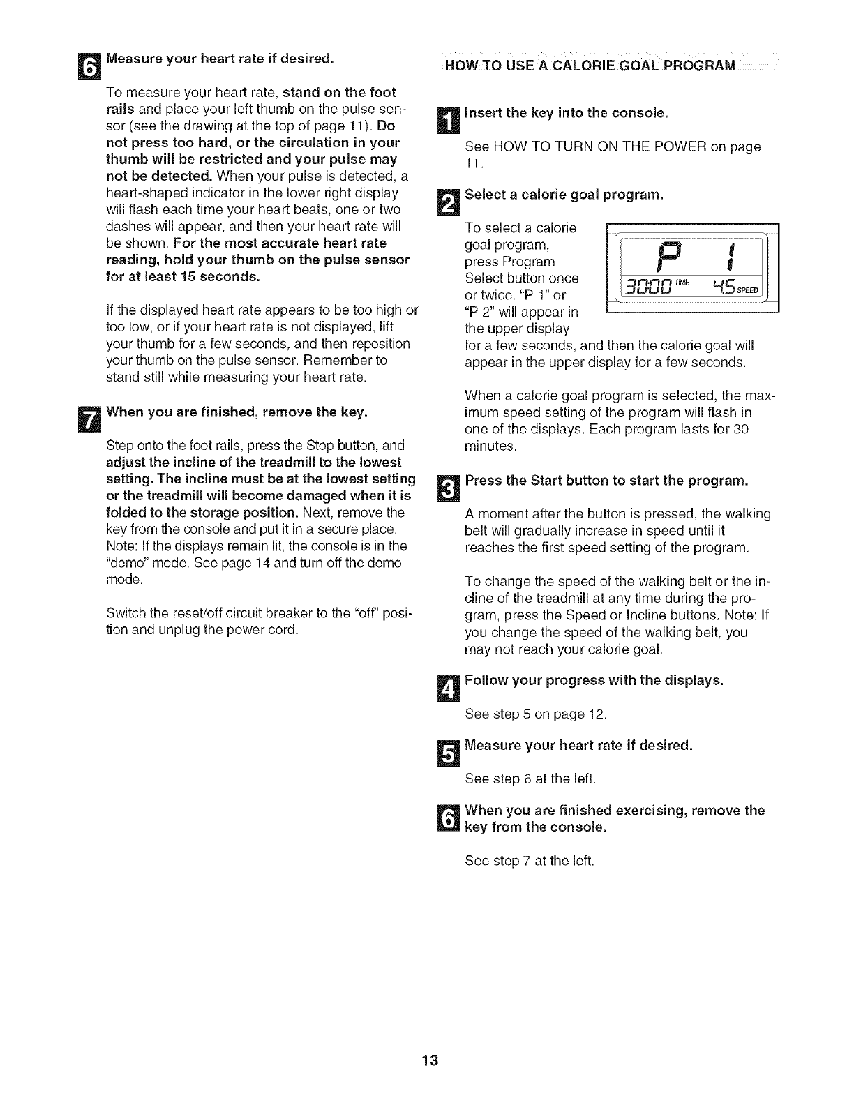
Select a calorie goal program.
To select a calorie
goal program,
press Program
Select button once
or twice. "P 1" or
"P 2" will appear in
the upper display
_
for a few seconds, and then the calorie goal will
appear in the upper display for a few seconds.
When a calorie goal program is selected, the max-
imum speed setting of the program will flash in
one of the displays. Each program lasts for 30
minutes.
Press the Start button to start the program.
A moment after the button is pressed, the walking
belt will gradually increase in speed until it
reaches the first speed setting of the program.
To change the speed of the walking belt or the in-
cline of the treadmill at any time during the pro-
gram, press the Speed or incline buttons. Note: If
you change the speed of the walking belt, you
may not reach your calorie goal.
Follow your progress with the displays.
See step 5 on page 12.
Measure your heart rate if desired.
See step 6 at the left.
When you are finished exercising, remove the
key from the console.
See step 7 at the left.
13
THE INFORMATION MODE/DEMO MODE
The console features an information mode that keeps
track of treadmill usage information and allows you to
select a unit of measurement for the console.
To select the information mode, hold down the Stop
button, insert the key into the console, wait until you
hear a tone, and then release the Stop button. The fol-
lowing information will then be shown:
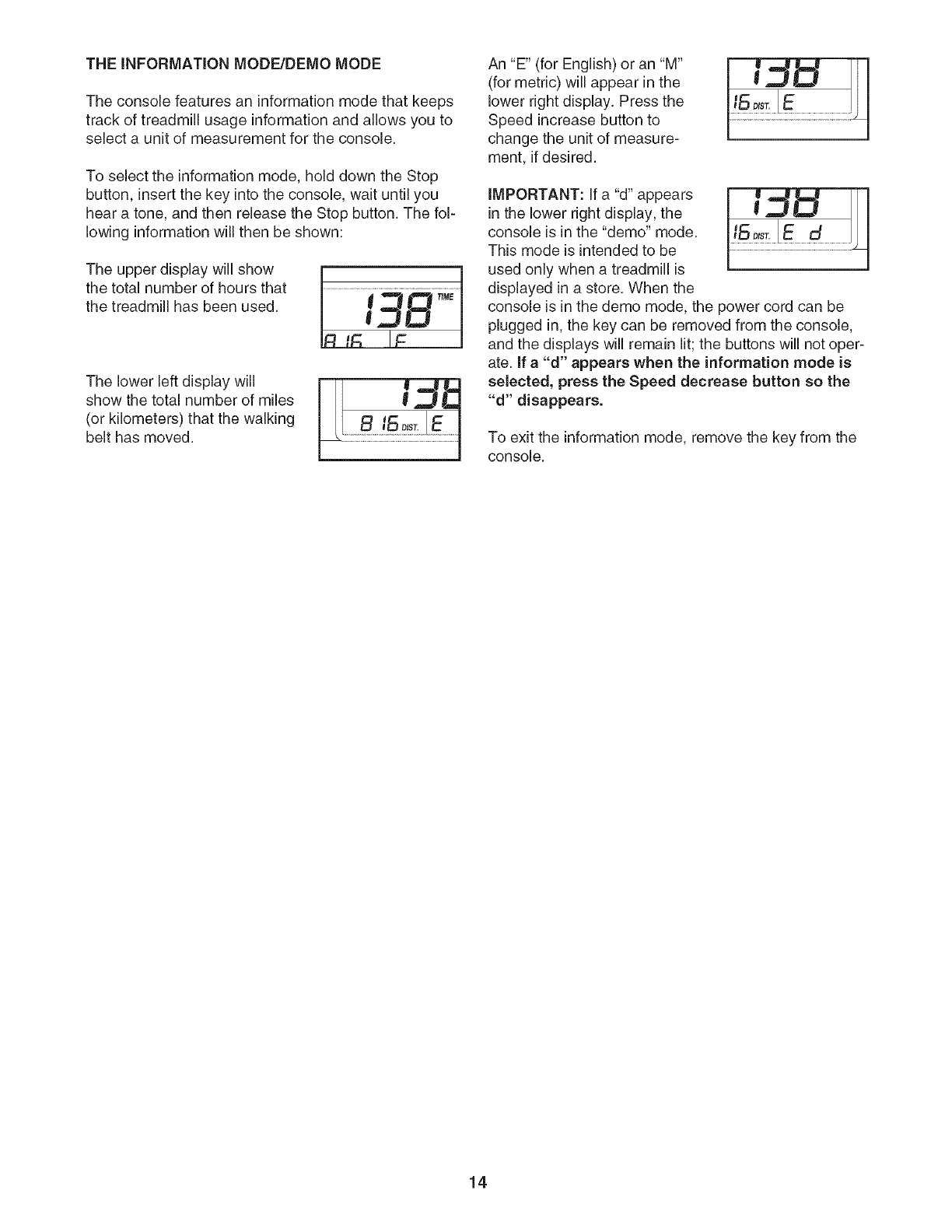
The upper display will show
the total number of hours that
the treadmill has been used. 19BTM
The lower left display will
show the total number of miles
(or kilometers) that the walking
belt has moved.
An "E" (for English) or an "M"
(for metric) will appear in the
lower right display. Press the
Speed increase button to
change the unit of measure-
ment, if desired.
IMPORTANT: If a "d" appears
in the lower right display, the
console is in the "demo" mode.
This mode is intended to be
used only when a treadmill is
displayed in a store. When the
console is in the demo mode, the power cord can be
plugged in, the key can be removed from the console,
and the displays will remain lit; the buttons will not oper-
ate. If a "d" appears when the information mode is
selected, press the Speed decrease button so the
"d" disappears.
To exit the information mode, remove the key from the
console.
14
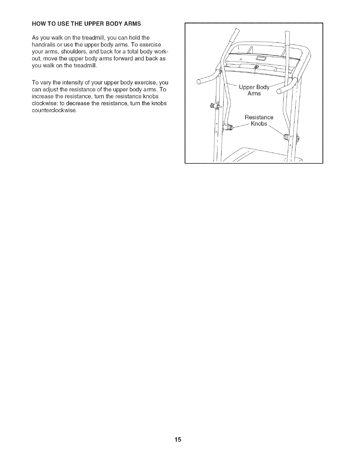
HOW TO USE THE UPPER BODY ARMS
As you walk on the treadmill, you can hold the
handrails or use the upper body arms. To exercise
your arms, shoulders, and back for a total body work-
out, move the upper body arms forward and back as
you walk on the treadmill.
To vary the intensity of your upper body exercise, you
can adjust the resistance of the upper body arms. To
increase the resistance, turn the resistance knobs
clockwise; to decrease the resistance, turn the knobs
counterclockwise.
15
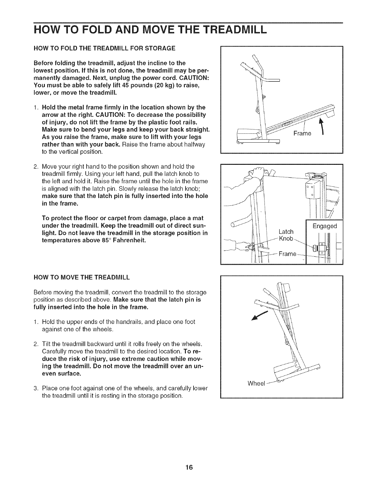
HOW TO FOLD AND MOVE THE TREADMILL
HOW TO FOLD THE TREADMILL FOR STORAGE
Before folding the treadmill, adjust the incline to the
Jowest position. If this is not done, the treadmill may be per-
manently damaged. Next, unplug the power cord. CAUTION:
You must be able to safely lift 45 pounds (20 kg) to raise,
Jower, or move the treadmiJL
1. Hold the metal frame firmly in the location shown by the
arrow at the right. CAUTION: To decrease the possibility
of injury, do not lift the frame by the plastic foot rails.
Make sure to bend your legs and keep your back straight.
As you raise the frame, make sure to Jilt with your legs
rather than with your back. Raise the frame about halfway
to the vertical position.
2. Move your right hand to the position shown and hold the
treadmill firmly. Using your left hand, pull the latch knob to
the left and hold it. Raise the frame until the hole in the frame
is aligned with the latch pin. Slowly release the latch knob;
make sure that the latch pin is fully inserted into the hole
in the frame.
To protect the floor or carpet from damage, place a mat
under the treadmill. Keep the treadmill out of direct sun-
light. Do not leave the treadmill in the storage position in
temperatures above 85 ° Fahrenheit.
Frame
Engaged
Latch
Frame _
HOW TO MOVE THE TREADMILL
Before moving the treadmill, convert the treadmill to the storage
position as described above. Make sure that the latch pin is
fully inserted into the hole in the frame.
1. Hold the upper ends of the handrails, and place one foot
against one of the wheels.
2. Tilt the treadmill backward until it rolls freely on the wheels.
Carefully move the treadmill to the desired location. To re-
duce the risk of injury, use extreme caution while mov-
ing the treadmill. Do not move the treadmill over an un-
even surface.
3. Place one foot against one of the wheels, and carefully lower
the treadmill until it is resting in the storage position.
Wheel
16
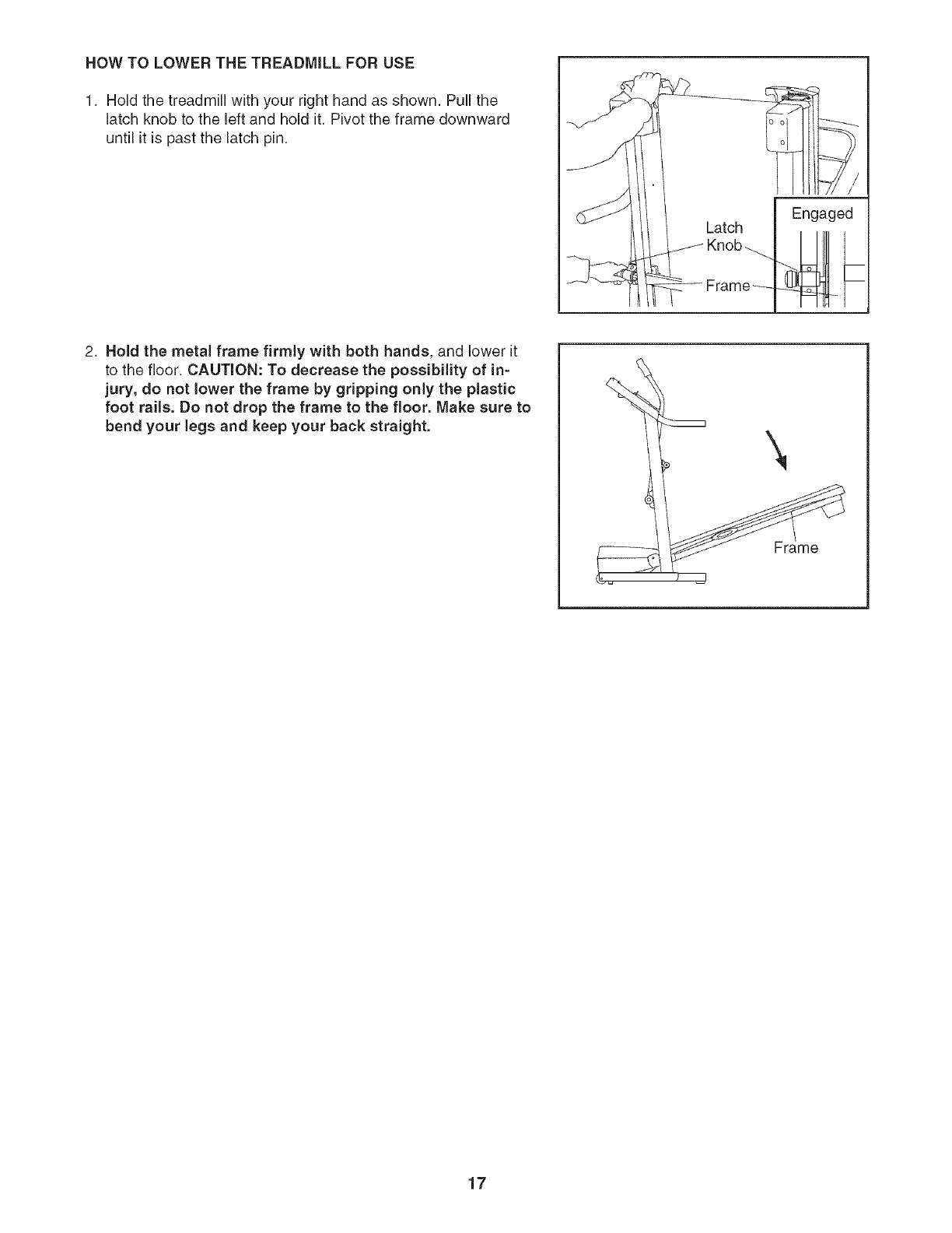
HOW TO LOWER THE TREADMILL FOR USE
1. Hold the treadmill with your right hand as shown. Pull the
latch knob to the left and hold it. Pivot the frame downward
until it is past the latch pin.
Engaged
2. Hold the metal frame firmly with both hands, and lower it
to the floor. CAUTION: To decrease the possibility of in-
jury, do not lower the frame by gripping only the plastic
foot rails. Do not drop the frame to the floor. Make sure to
bend your legs and keep your back straight. \
Frame
17
TROUBLESHOOTING
Most treadmill problems can be solved by following the simple steps below. Find the symptom that
applies, and follow the steps listed. If further assistance is needed, call toll-free 1-800-4-MY-HOME ®
(1-800-469-4663).
PROBLEM: The power does not turn on
SOLUTION: a. Make sure that the power cord is plugged into a surge suppressor, and that the surge suppressor
is plugged into a properly grounded outlet (see page 10). Use only a single-outlet surge suppres-
sor that meets all of the specifications described on page 10. Important: The treadmill is not com-
patible with GFCl-equipped outlets.
b. After the power cord has been plugged in, make sure that the key is inserted into the console.
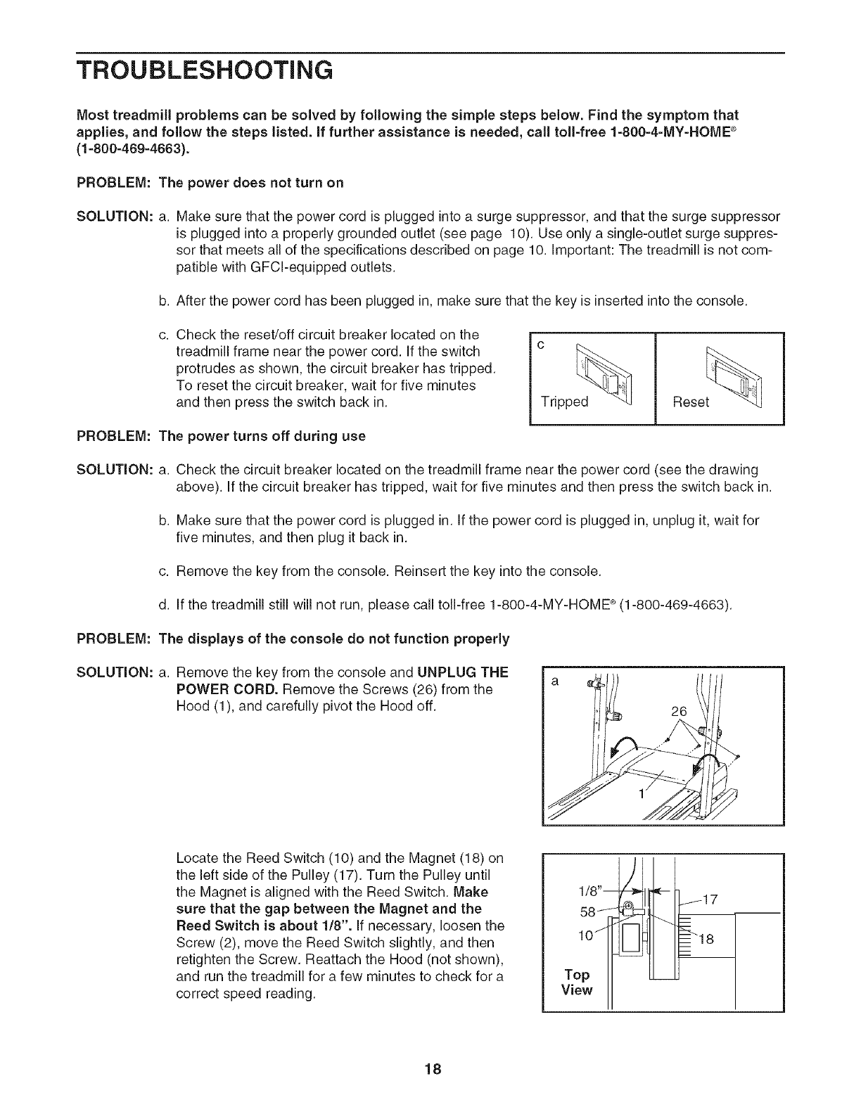
Check the reset/off circuit breaker located on the
treadmill frame near the power cord. If the switch
protrudes as shown, the circuit breaker has tripped.
To reset the circuit breaker, wait for five minutes
and then press the switch back in.
PROBLEM: The power turns off during use
Rese_
SOLUTION: a. Check the circuit breaker located on the treadmill frame near the power cord (see the drawing
above). If the circuit breaker has tripped, wait for five minutes and then press the switch back in.
b. Make sure that the power cord is plugged in. If the power cord is plugged in, unplug it, wait for
five minutes, and then plug it back in.
c. Remove the key from the console. Reinsert the key into the console.
d. If the treadmill still will not run, please call toll-free 1-800-4-MY-HOME ®(1-800-469-4663).
PROBLEM: The displays of the console do not function properly
SOLUTION: a. Remove the key from the console and UNPLUG THE
POWER CORD. Remove the Screws (26) from the
Hood (1), and carefully pivot the Hood off. 26
Locate the Reed Switch (10) and the Magnet (18) on
the left side of the Pulley (17). Turn the Pulley until
the Magnet is aligned with the Reed Switch. Make
sure that the gap between the Magnet and the
Reed Switch is about 1/8". Jfnecessary, loosen the
Screw (2), move the Reed Switch slightly, and then
retJghten the Screw. Reattach the Hood (not shown),
and run the treadmill for a few minutes to check for a
correct speed reading.
1/8"dl
Top
View
18
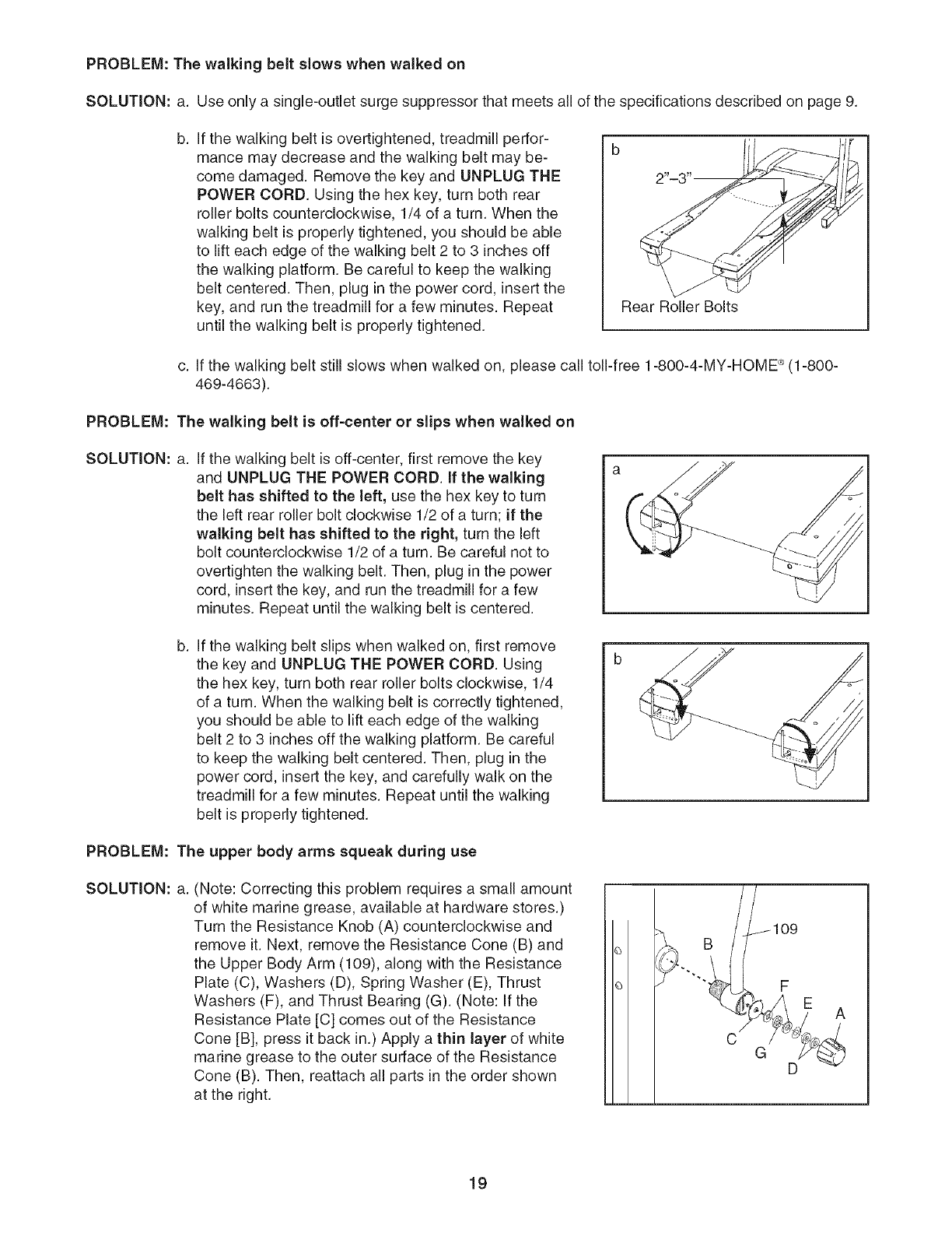
PROBLEM: The walking belt slows when walked on
SOLUTION: a. Use only a single-outlet surge suppressor that meets all of the specifications described on page 9.
b. If the walking belt is overtightened, treadmill perfor-
mance may decrease and the walking belt may be-
come damaged. Remove the key and UNPLUG THE
POWER CORD. Using the hex key, turn both rear
roller bolts counterclockwise, 1/4 of a turn. When the
walking belt is properly tightened, you should be able
to lift each edge of the walking belt 2 to 3 inches off
the walking platform. Be careful to keep the walking
belt centered. Then, plug in the power cord, insert the
key, and run the treadmill for a few minutes. Repeat
until the walking belt is properly tightened.
Rear Roller Bolts
c. If the walking belt still slows when walked on, please call toll-free 1-800-4-MY-HOME _ (1-800-
469-4663).
PROBLEM: The walking belt is off-center or slips when walked on
SOLUTION: a. If the walking belt is off-center, first remove the key
and UNPLUG THE POWER CORD. If the walking
belt has shifted to the left, use the hex key to turn
the left rear roller bolt clockwise 1/2 of a turn; if the
walking belt has shifted to the right, turn the left
bolt counterclockwise 1/2 of a turn. Be careful not to
overtighten the walking belt. Then, plug in the power
cord, insert the key, and run the treadmill for a few
minutes. Repeat until the walking belt is centered.
b. If the walking belt slips when walked on, first remove
the key and UNPLUG THE POWER CORD. Using
the hex key, turn both rear roller bolts clockwise, 1/4
of a turn. When the walking belt is correctly tightened,
you should be able to lift each edge of the walking
belt 2 to 3 inches off the walking platform. Be careful
to keep the walking belt centered. Then, plug in the
power cord, insert the key, and carefully walk on the
treadmill for a few minutes. Repeat until the walking
belt is properly tightened.
PROBLEM: The upper body arms squeak during use
SOLUTION: a. (Note: Correcting this problem requires a small amount
of white marine grease, available at hardware stores.)
Turn the Resistance Knob (A) counterclockwise and
remove it. Next, remove the Resistance Cone (B) and
the Upper Body Arm (109), along with the Resistance
Plate (C), Washers (D), Spring Washer (E), Thrust
Washers (F), and Thrust Bearing (G). (Note: If the
Resistance Plate [C] comes out of the Resistance
Cone [B], press it back in.) Apply a thin layer of white
marine grease to the outer surface of the Resistance
Cone (B). Then, reattach all parts in the order shown
at the right.
43
GD
19
CONDiTiONiNG GUiDELiNES
ergy. Only after the first few minutes does your body
begin to use stored fat oa/ofies for energy. If your goal
is to burn fat, adjust the speed and incline of the tread-
mill until your heart rate is near the lowest number in
your training zone.
For maximum fat burning, adjust the speed and incline
of the treadmill until your heart rate is near the middle
number in your training zone.
Aerobic Exercise
The following guidelines will help you to plan your ex-
ercise program. For more detailed exercise informa-
tion, obtain a reputable book or consult your physician.
EXERCISEINTENSITY
prolonged periods of time. This increases the demand
on the heart to pump blood to the muscles, and on the
lungs to oxygenate the blood. For aerobic exercise,
adjust the speed and incline of the treadmill until your
heart rate is near the highest number in your training
zone.
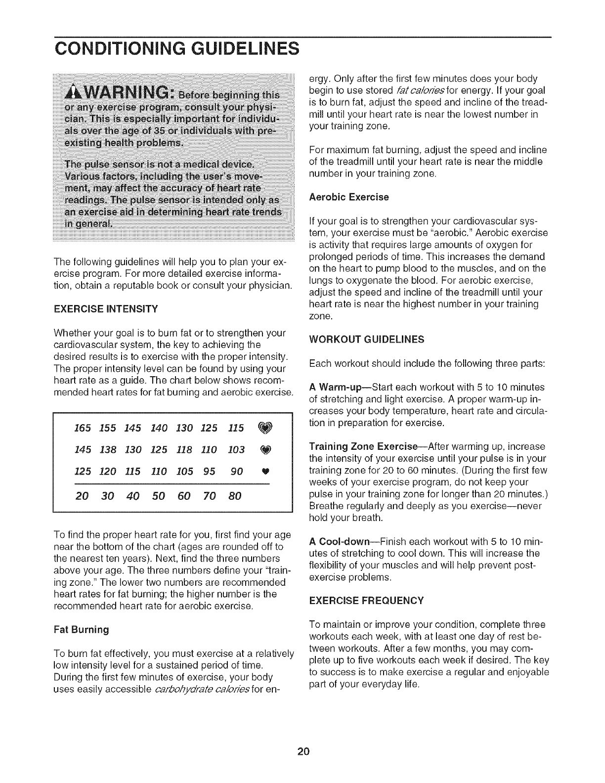
Whether your goal is to burn fat or to strengthen your
cardiovascular system, the key to achieving the
desired results is to exercise with the proper intensity.
The proper intensity level can be found by using your
heart rate as a guide. The chart below shows recom-
mended heart rates for fat burning and aerobic exercise.
165 155 145 140 130 125 115 _
145 138 130 125 !18 110 103 q.w)
125 120 115 110 105 95 90
20 30 40 50 60 70 80
To find the proper heart rate for you, first find your age
near the bottom of the chart (ages are rounded off to
the nearest ten years). Next, find the three numbers
above your age. The three numbers define your "train-
ing zone." The lower two numbers are recommended
heart rates for fat burning; the higher number is the
recommended heart rate for aerobic exercise.
WORKOUT GUiDELiNES
Each workout should include the following three parts:
AWarm-up--Start each workout with 5 to 10 minutes
of stretching and light exercise. A proper warm-up in-
creases your body temperature, heart rate and circula-
tion in preparation for exercise.
Training Zone Exercise--After warming up, increase
the intensity of your exercise until your pulse is in your
training zone for 20 to 60 minutes. (During the first few
weeks of your exercise program, do not keep your
pulse in your training zone for longer than 20 minutes.)
Breathe regularly and deeply as you exercise--never
hold your breath.
ACool-down--Finish each workout with 5 to 10 min-
utes of stretching to cool down. This will increase the
flexibility of your muscles and will help prevent post-
exercise problems.
EXERCISEFREQUENCY
Fat Burning
To burn fat effectively, you must exercise at a relatively
low intensity level for a sustained period of time.
During the first few minutes of exercise, your body
uses easily accessible carbohydrate oa/ories for en-
To maintain or improve your condition, complete three
workouts each week, with at least one day of rest be-
tween workouts. After a few months, you may com-
plete up to five workouts each week if desired. The key
to success is to make exercise a regular and enjoyable
part of your everyday life.
2O
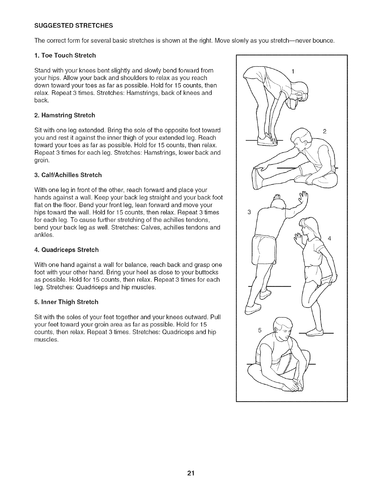
SUGGESTED STRETCHES
The correct form for several basic stretches is shown at the right. Move slowly as you stretch--never bounce.
1. Toe Touch Stretch
Stand with your knees bent slightly and slowly bend forward from
your hips. Allow your back and shoulders to relax as you reach
down toward your toes as far as possible. Hold for 15 counts, then
relax. Repeat 3 times. Stretches: Hamstrings, back of knees and
back.
2. Hamstring Stretch
Sit with one leg extended. Bring the sole of the opposite foot toward
you and rest it against the inner thigh of your extended leg. Reach
toward your toes as far as possible. Hold for 15 counts, then relax.
Repeat 3 times for each leg. Stretches: Hamstrings, lower back and
groin.
3. Calf/Achilles Stretch
With one leg in front of the other, reach forward and place your
hands against a wall. Keep your back leg straight and your back foot
flat on the floor. Bend your front leg, lean forward and move your
hips toward the wall. Hold for 15 counts, then relax. Repeat 3 times
for each leg. To cause further stretching of the achilles tendons,
bend your back leg as well. Stretches: Calves, achilles tendons and
ankles.
4. Quadriceps Stretch
With one hand against a wail for balance, reach back and grasp one
foot with your other hand. Bring your heel as close to your buttocks
as possible. Hold for 15 counts, then relax. Repeat 3 times for each
leg. Stretches: Quadriceps and hip muscles.
5. Inner Thigh Stretch
Sit with the soles of your feet together and your knees outward. Pull
your feet toward your groin area as far as possible. Hold for 15
counts, then relax. Repeat 3 times. Stretches: Quadriceps and hip
muscles.
21

NOTES
22
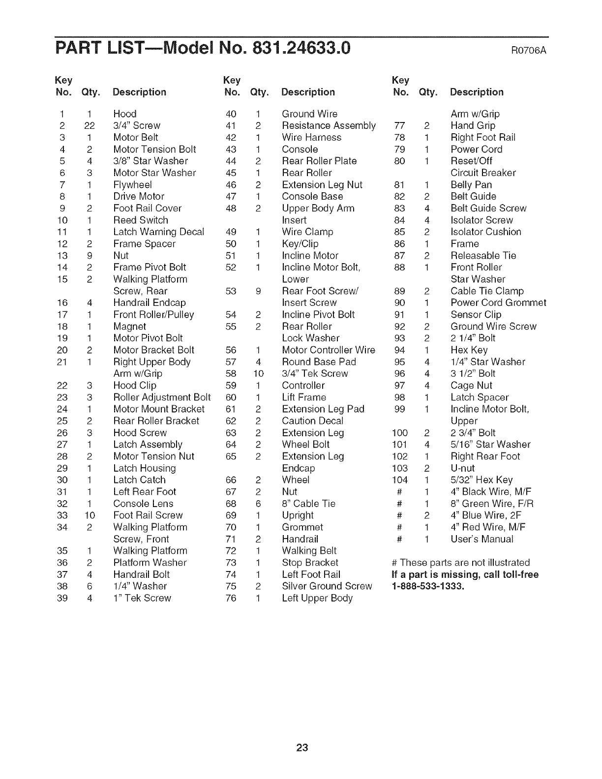
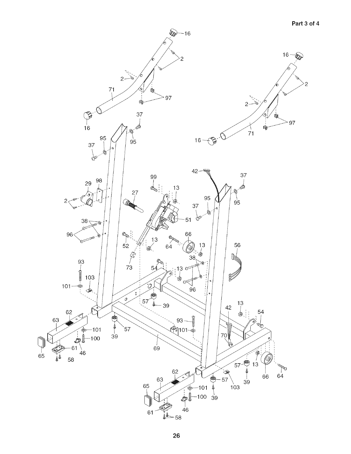
PART LIST--Model No. 831.24633.0 R0706A
Key Key Key
No. Qty. Description No. Qty. Description No. Qty. Description
1 1 Hood 40 1 Ground Wire
2 22 3/4" Screw 41 2 Resistance Assembly
3 1 Motor Belt 42 1 Wire Harness
4 2 Motor Tension Bolt 43 1 Console
5 4 3/8" Star Washer 44 2 Rear Roller Plate
6 3 Motor Star Washer 45 1 Rear Roller
7 1 Flywheel 46 2 Extension Leg Nut
8 1 Drive Motor 47 1 Console Base
9 2 Foot Rail Cover 48 2 Upper Body Arm
10 1 Reed Switch Insert
11 1 Latch Warning Decal 49 1 Wire Clamp
12 2 Frame Spacer 50 1 Key/Clip
13 9 Nut 51 1 Incline Motor
14 2 Frame Pivot Bolt 52 1 Incline Motor Bolt,
15 2 Walking Platform Lower
Screw, Rear 53 9 Rear Foot Screw/
16 4 Handrail Endcap Insert Screw
17 1 Front Roller/Pulley 54 2 Incline Pivot Bolt
18 1 Magnet 55 2 Rear Roller
19 1 Motor Pivot Bolt Lock Washer
20 2 Motor Bracket Bolt 56 1 Motor Controller Wire
21 1 Right Upper Body 57 4 Round Base Pad
Arm w/Grip 58 10 3/4" Tek Screw
22 3 Hood Clip 59 1 Controller
23 3 Roller Adjustment Bolt 60 1 Lift Frame
24 1 Motor Mount Bracket 61 2 Extension Leg Pad
25 2 Rear Roller Bracket 62 2 Caution Decal
26 3 Hood Screw 63 2 Extension Leg
27 1 Latch Assembly 64 2 Wheel Bolt
28 2 Motor Tension Nut 65 2 Extension Leg
29 1 Latch Housing Endcap
30 1 Latch Catch 66 2 Wheel
31 1 Left Rear Foot 67 2 Nut
32 1 Console Lens 68 6 8" Cable Tie
33 10 Foot Rail Screw 69 1 Upright
34 2 Walking Platform 70 1 Grommet
Screw, Front 71 2 Handrail
35 1 Walking Platform 72 1 Walking Belt
36 2 Platform Washer 73 1 Stop Bracket
37 4 Handrail Bolt 74 1 Left Foot Rail
38 6 1/4" Washer 75 2 Silver Ground Screw
39 4 1" Tek Screw 76 1 Left Upper Body
Arm w/Grip
77 2 Hand Grip
78 1 Right Foot Rail
79 1 Power Cord
80 1 Reset/Off
Circuit Breaker
81 1 Belly Pan
82 2 Belt Guide
83 4 Belt Guide Screw
84 4 Isolator Screw
85 2 Isolator Cushion
86 1 Frame
87 2 Releasable Tie
88 1 Front Roller
Star Washer
89 2 Cable Tie Clamp
90 1 Power Cord Grommet
91 1 Sensor Clip
92 2 Ground Wire Screw
93 2 2 1/4" Bolt
94 1 Hex Key
95 4 1/4" Star Washer
96 4 3 1/2" Bolt
97 4 Cage Nut
98 1 Latch Spacer
99 1 Incline Motor Bolt,
Upper
100 2 2 3/4" Bolt
101 4 5/16" Star Washer
102 1 Right Rear Foot
103 2 U-nut
104 1 5/32" Hex Key
# 1 4" Black Wire, M/F
# 1 8" Green Wire, F/R
# 2 4" Blue Wire, 2F
# 1 4" Red Wire, M/F
# 1 User's Manual
# These parts are not illustrated
if apart is missing, call toll-free
1=888=533=1333.
23
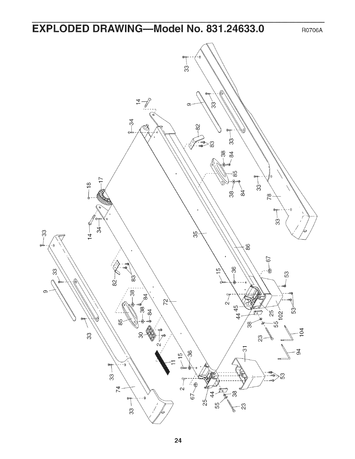
EXPLODED DRAWING--iVlodei No. 831.24633.0 Rozo6A
CO _
03 cO
CO '_"
CO CO
co
co
kO
,r-
CO
CO
03
kO
kO
C,J
C,J
_ ("4
0
03
kO
24
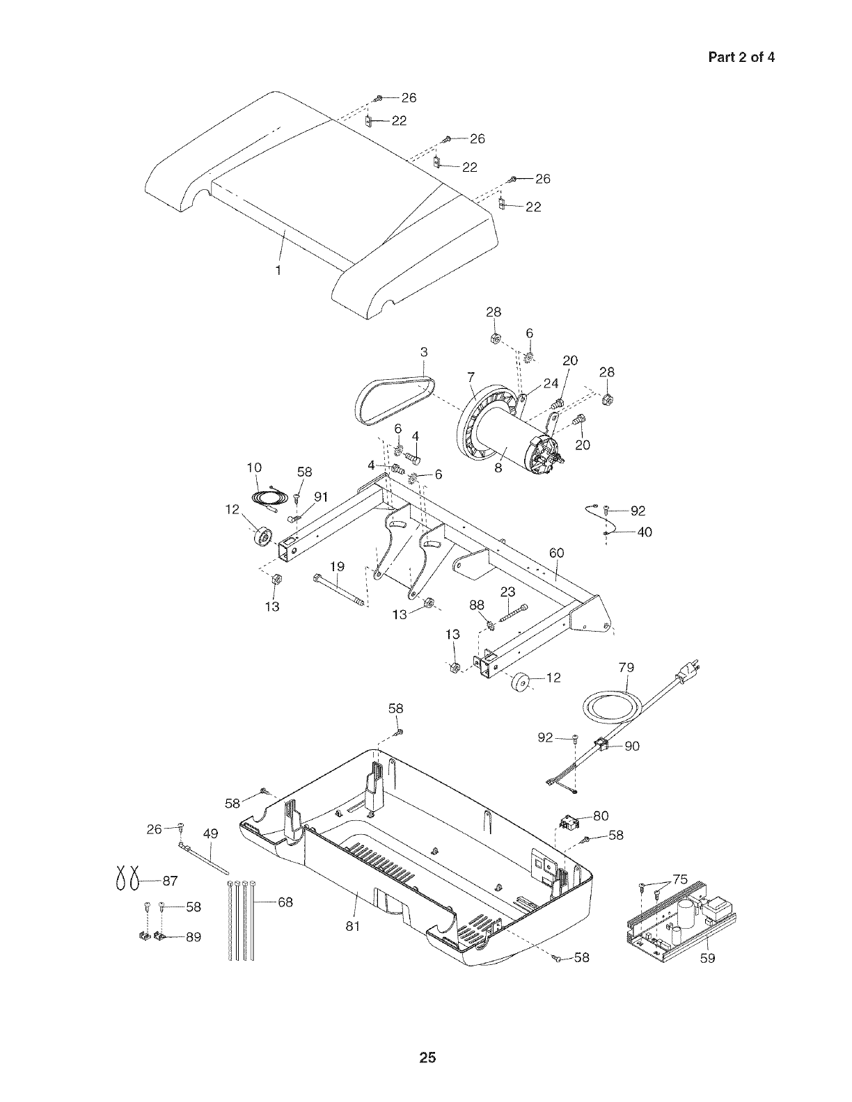
Part 2 of 4
20 28
10 58
20
19
58
60
79
81
25
'_16
Part 3 of 4
16
95
37
37
95
71
65
29
46
58
62
63
39
99
27 _ii
13
39
69
63
65
61
13
95
37
66
38
96
62
58
37
95
13
t
39
103
54
66 64
26
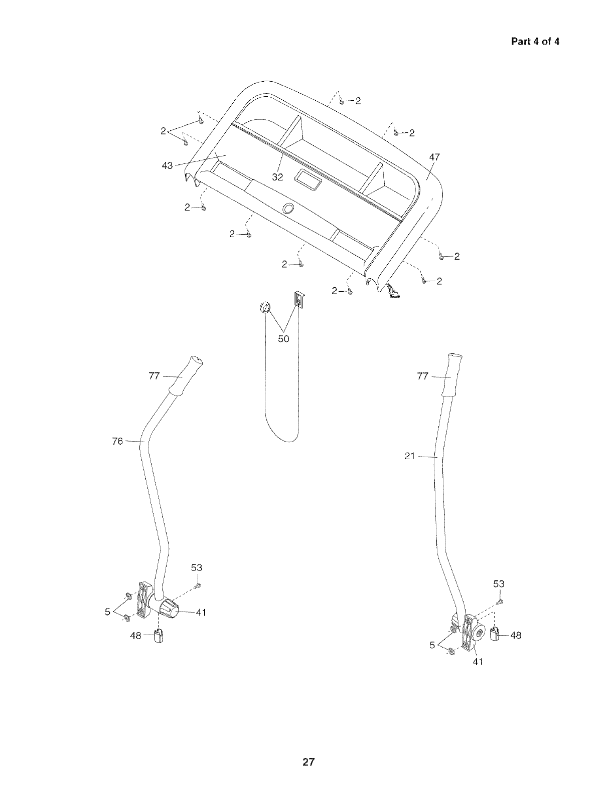
Part 4 of 4
47
77--
i
48-I_
41
27

Your Home
For repair--in your home--of all major brand appliances, lawn and garden equipment,
or heating and cooling systems, no matter who made it, no matter who sold it!
iiiiiiiiiiiiiii_
For the replacement parts, accessories, and user's manuals that you need to do-it-yourself.
iiiiiiiiiiiiiiii For Sears professional installation of home appliances
and items like garage door openers and water heaters.
iiiiiiiiiiiiiii_
1-800-4-MY-HOME ® (1-800-469-4663)
Call anytime, day or night (U.S.A. and Canada)
www.,eo,,.oomwww.,ear,.ca
Our Home
For repair of carry-in items like vacuums, lawn equipment,
and electronics, call or go on-line for the location of your nearest
SearsParts,°pairCeoter.
HHHHHHHi_
1"800"488-1222 Call anytime, day or night (U.S.A. only)
www.sears.con,
To purchase a protection agreement (U.S.A.)
or maintenance agreement (Canada) on a product serviced by Sears:
1-800-827-6655 (U.S.A.) 1-800-361-6665 (Canada) iiiiiiiiiiiiii
® Registered Trademark /TMTrademark /SMService Mark of Sears Brands, LLC
® Marca Registrada /TMMarca de Fabrica /SMMarca de Servicio de Sears Brands, LLC
f
90 DAY FULL WARRANTY
If this Sears Treadmill Exerciser fails due to a defect in material or workmanship within 90 days of the
date of purchase, call 1-800-4-MY-HOME _ (1-800-469-4663) to arrange for free repair (or replacement if
repair proves impossible). The drive motor is warranted for 3 years from the date of purchase.
This warranty does not apply when the Treadmill Exerciser is used commercially or for rental purposes.
This warranty gives you specific legal rights, and you may also have other rights which vary from state to
state.
Sears, Roebuck and Co., Hoffman Estates, IL 60179
J
J
Part No. 241520 RO706A Printed in USA © 2006 ICON IP, Inc.
