Proform 831297643 User Manual SPACE SAVER 580 SI Manuals And Guides 99020106
PROFORM Treadmill Manual 99020106 PROFORM Treadmill Owner's Manual, PROFORM Treadmill installation guides
User Manual: Proform 831297643 831297643 PROFORM PROFORM SPACE SAVER 580 SI - Manuals and Guides View the owners manual for your PROFORM PROFORM SPACE SAVER 580 SI #831297643. Home:Fitness Equipment Parts:Proform Parts:Proform PROFORM SPACE SAVER 580 SI Manual
Open the PDF directly: View PDF ![]() .
.
Page Count: 16
PRO.FORM
SEARS
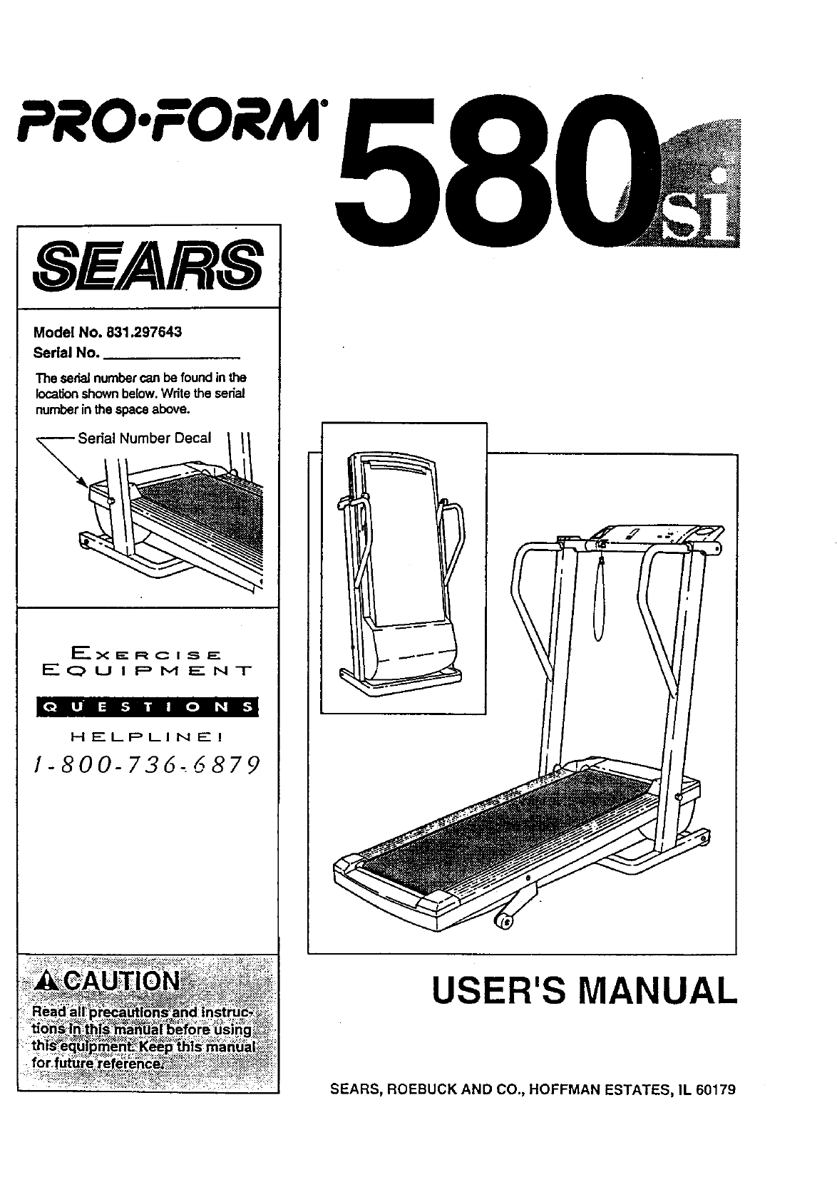
Model No. 831.297643
Serial No.
The serialnumbercan be foundinthe
locationshownbelow.Writetheserial
numberinthe spaceabove.
Number Decal
_____.X _" R C I S, F_.
EQUIPMENT
HELPLINE!
1-800-736_6879
USER'S MANUAL
SEARS, ROEBUCK AND CO., HOFFMAN ESTATES, IL 60179
PRO.FORM
TABLE OF CONTENTS
IMPORTANT PRECAUTIONS ................................................................. 3
BEFORE YOU BEGIN ....................................................................... 4
ASSEMBLY ............................................................................... 5
OPERATION AND ADJUSTMENT ............................................................. 7
HOW TO FOLD AND MOVE THE TREADMILL .................................................. 10
TROUBLE-SHOOTING AND STORAGE ........................................................ 12
CONDITIONING GUIDELINES ............................................................... 14
ORDERING REPLACEMENT PARTS .................................................. Back Cover
FULL 90 DAY WARRANTY ........................................................... Back Cover
Note: An EXPL(JDED DRAWING and a PART LIST are attached to the center of this manual. Save the
EXPLODED DRAWING and PART LIST for future reference.
per
.:::.:ReEd all
::::_'amage s_stalned by:p_"through the use of this product.
_:_'i:_:_.:,.-. . .... _:...r ,, _>, ". _....: : . .:..:* : : .: . .[:

BEFORE YOU BEGIN
Thank you for selecting the unique PROFORM ° 580si
treadmill. The 580si treadmill blends advanced technol-
ogy with innovative styling to let you enjoy an excellent
form of cardiovascular exercise in the convenience and
privacy of your home. The 580si offers an impressive
array of features to make your workouts more enjoy-
able and effective. And when you're not exemising, the
580si can be folded up, requiring less than half the floor
• space of other treadmills.
For your benefit, reacl this manual carefully before
using the treadmill. If youhave additional questions,
please call our toll-free HELPLINE at 1-800-736-6879,
Monday through Saturday, 7 a.m. until 7 p.m. Central
Time (excluding holidays). To he!p us assist you,
please note the product model number and seriai num-
ber before-calling. The model number of the treadmill
is 831.297643. The sedal number can be found on a
decal attached to the treadmill (see the front cover of
this manual for the location).
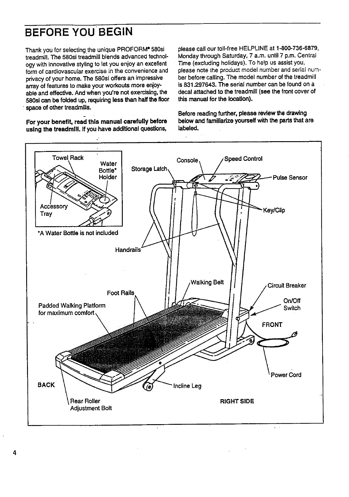
Before reading further, please review the drawing
below and familiarize yourself with the parts that are
labeled.
Towel Rack
Tray
Storage Latch
CoNsole
*A Water Bottle is not included
Handrails"
Walking Belt Breaker
Padded Walking Platform On/Off
FRONT
BACK
Rear Roller
Adjustment Bolt
Leg
RIGHT SIDE
4
ASSEMBLY
Assembly requires two people. Set the treadmill in acleared area and remove all packing materials. Do not dis-
pose of the packing materials until assembly is completed. Tools required for assembly: The included allen
wrench _ and your phillips screwdriver _and two adjustable wrenches _ .
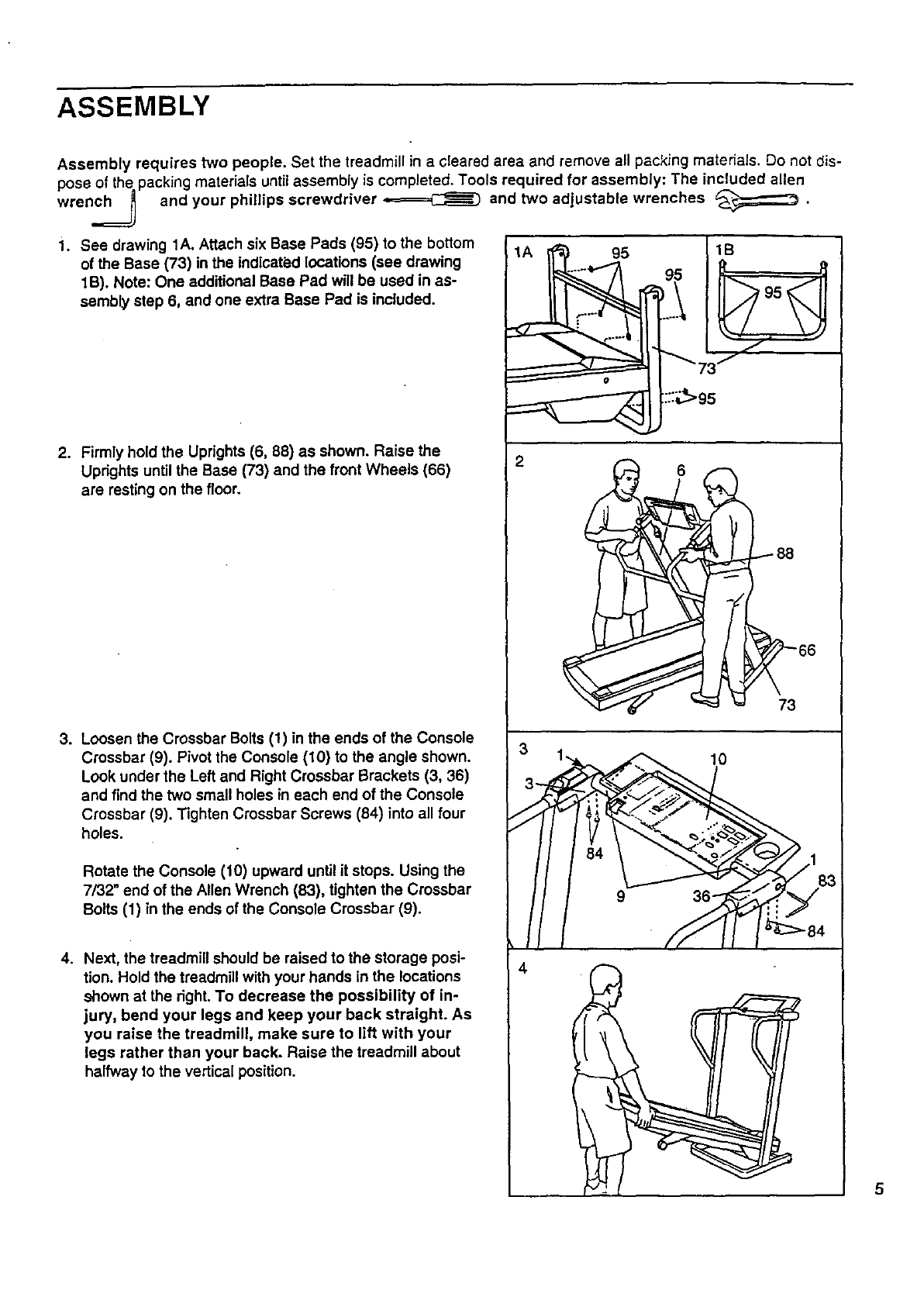
i. See drawing 1A. Attach six Base Pads (95) to the bottom
of the Base (73) in the indicated locations (see drawing
1B). Note: One additional Base Pad will be used in as-
sembly step 6, and one extra Base Pad is included.
2. Firmly hold the Uprights (6. 88) as shown. Raise the
Uprights until the Base (73) and the front Wheels (66)
are resting on the floor.
3. Loosen the Crossbar Bolts (1) in the ends of the Console
Crossbar (9). Pivot the Console (10) to the angle shown.
Look under the Left and Right Crossbar Brackets (3, 36)
and find the two small holes in each end of the Console
Crossbar (9). Tighten Crossbar Screws (84) into all four
holes.
Rotate the Console (10) upward until it stops. Using the
7/32" end of the Allen Wrench (83), tighten the Crossbar
Bolts (1) in the ends of the Console Crossbar (g).
4. Next, the treadmill should be raised to the storage posi-
tion. Hold the treadmill with your hands in the locations
shown at the right. To decrease the possibility of in-
jury, bend your legs and keep your back straight. As
you raise the treadmill, make sure to lift with your
legs rather than your back. Raise the treadmill about
halfway to the vertical position.
1A
2
1B I
9i
f:::_>95
P f -88
31,,,A_f"_ 10
3 "i
9 38
183
J
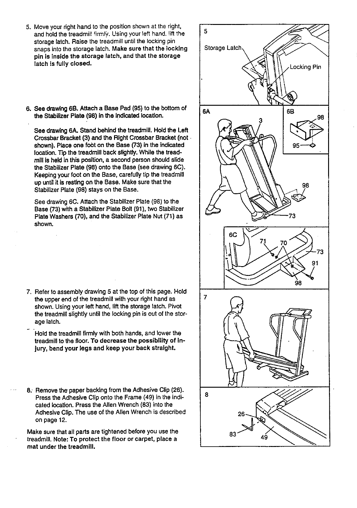
5. Move your right hand to the position shown at the right,
and hold the treadmii_ firmly. Using your left hand. !iff the
storage latch. Raise the treadmill until the locking pin
snaps into the storage latch. Make sure that the locking
pin is inside the storage latch, and that the storage
latch is fully closed.
.See drawing 6B. Attach a Base Pad (95) to the bottom of
the Stabilizer Plate (98) in the indicated location.
See drawing 6A. Stand behind the treadmill. Hold the Left
Crossbar Bracket (3) and the Right Crossbar Bracket (not
shown). Place one fobt on the Base (73) in the indicated
location. Tip the treadmill back slightly.While the tread-
mill is held in this position, asecond person should slide
the Stabilizer Plate (98) onto the Base (see drawing 6C).
Keeping your foot on the Base, carefully tip the treadmill
up until it is resting on the Base. Make sure that the
Stabilizer Plate (98) stays on the Base.
See drawing 6C. Attach the Stabilizer Plate (98) to the
Base (73) with aStabilizer Plate Bolt (91), two Stabilizer
Plate Washers (70), and the Stabilizer Plate Nut (71) as
shown.
.Refer to assembly drawing 5 at the top of this page. Hold
the upper end of the treadmill with your right hand as
shown. Using your left hand, liftthe storage latch. Pivot
the treadmill slightly until the locking pin is out of the stor-
age latch.
°Hold the treadmill firmly with both hands, and lower the
treadmill to the floor, To decrease the possibility of in-
jury, bend your legs and keep your back straight.
8: Remove the paper backing from the Adhesive Clip (26).
Press the Adhesive Clip onto the Frame (49) in the indi-
cated location. Press the Allen Wrench (83) into the
Adhesive Clip. The use of the Allen Wrench is described
on page 12.
Make sure that all parts are tightened before you use the
treadmill. Note: To protect the floor or carpet, place a
mat under the treadmill.
torage Latch_
6A 6B
95----_
98
7
,..._)/ 71,70"
49
OPERATION AND ADJUSTMENT
THE PERFORMANT LUBE TM WALKING BELT
Your treadmill features a walking belt coated with
PERFORMANT LUBE TM, a high-performance lubdcant.
IMPORTANT: Never apply silicone spray or other
substances to the walking belt or the walking plat-
form. They will deteriorate the walking belt and
cause excessive wear.
HOWTO PLUG IN THE POWER CORD
electric shock. This product is equipped with a cord
having an equlpment-grounding conductor and a
grounding plug. Plug the power cord into asurge
protector, and plug the surge protector into an ap-
propriate outlet that Is properly installed and
grounded in accordance with all local codes and
ordinances.
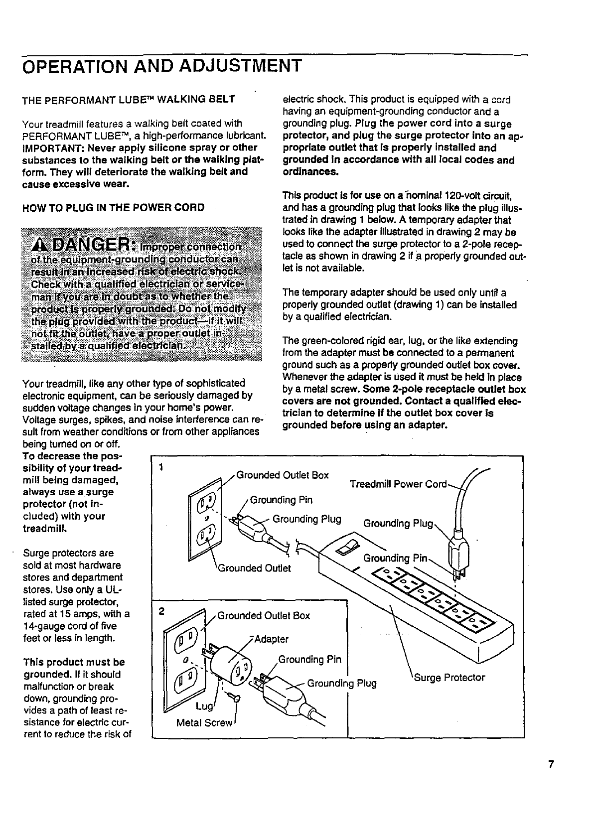
This product is for use on a ilomina1120-volt circuit,
and has a grounding plug that looks like the plug illus-
trated in drawing 1 below. A temporary adapter that
looks like the adapter illustrated in drawing 2 may be
used to connect the surge protector to a 2-pole recep-
tacle as shown in drawing 2 if _apropedy grounded out-
let is not available.
The temporary adapter should be used only until a
properly grounded outlet (drawing 1) can be installed
by a qualified electrician.
Your treadmill, like any other type of sophisticated
electronic equipment, can be seriously damaged by
sudden voltage changes in your home's power.
Voltage surges, spikes, and noise interference can re-
sult from weather conditions or from other appliances
being turned on or off.
To decrease the pos-
sibility of your tread- 1
mill being damaged,
always use a surge
protector (not In-
cluded) with your
treadmill.
Surge protectors are
sold at most hardware
stores and department
stores. Use only aUL-
listed surge protector,
rated at 15 amps, with a
14-gauge cord of five
feet or less in length.
This product must be
grounded. If it should
malfunction or break
down, grounding pro-
vides a path of least re-
sistance for electric cur-
rent to reduce the risk of
The green-colored rigid ear, lug, or the like extending
from the adapter must be connected to a permanent
ground such as aproperly grounded outlet box cover.
Whenever the adapter is used it must be held in place
by ametal screw. Some 2-pole receptacle outlet box
covers are not grounded, Contact a qualified elec-
trician to determine If the outlet box cover is
grounded before using an adapter.
jGrounded Outlet Box
Grounding Pin
"_unding Plug
_Grounded Outlet
Treadmill Power Cord--
Gmunding
€_,/Grounded Outlet Box
_.,/_Adapter
_. _ /.,,,:_ /Grounding Pin
(_. , Grounding Plug
Meta Screw
Surge Protector
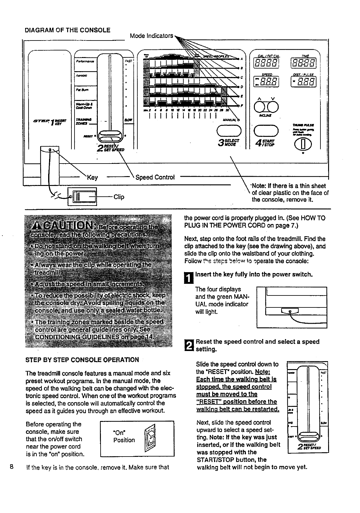
DIAGRAM OF THE CONSOLE Mode Indicators
IIIli
CD
\
f _ \
FAT L_M e
u_u_i
I
AV
O
\
'Note: If there is athin sheet
of clear plastic on the face of
the console, remove it.
the power cord is propedy plugged in. (See HOW TO
PLUG IN THE POWER CORD on page 7.)
Next, step onto the foot rails of the treadmill. Find the
clip attachedto the key (see the drawing above), and
slide the clip onto the waistband of your clothing.
Follow *.'_ ._t_s be!_.,.vto operate the console:
g Insert the key fully into the power switch.
The four displays It
and the green MAN-
UAL mode indicator
will light.
8
STEP BY STEP CONSOLE OPERATION
The treadmill console features a manual mode and six
preset workout programs. In the manual mode, the
speed of the walking belt can be changed with the elec-
tronic speed control. When oneof the workout programs
is selected, the console will automatically controlthe
speed as it guides you through an effective workout.
Before operating the I
console, make sure "On"
that the on/off switch Position
near the power cord
is in the =on" position,
if the key is in the console, remove it. Make sure that
_=_i Reset the speed control and select a speed
setting.
Slide the speed control down to
the "RESET" position. Note:
Each time the walklno belt is
Stopoed. the speed control
must be moved to the
"RESET" oositlon before the
walkina belt can be restarted.
•ii,4 II
=a i ,,
miH
Next, slide the speed control
upwardto select a speed set-
ting. Note: If the key was just
inserted, or if the walking belt
was stopped with the
START/STOP button, the
walking belt will not begin to move yet.
RF.$&'_'/
2 $_='t,_DtJED
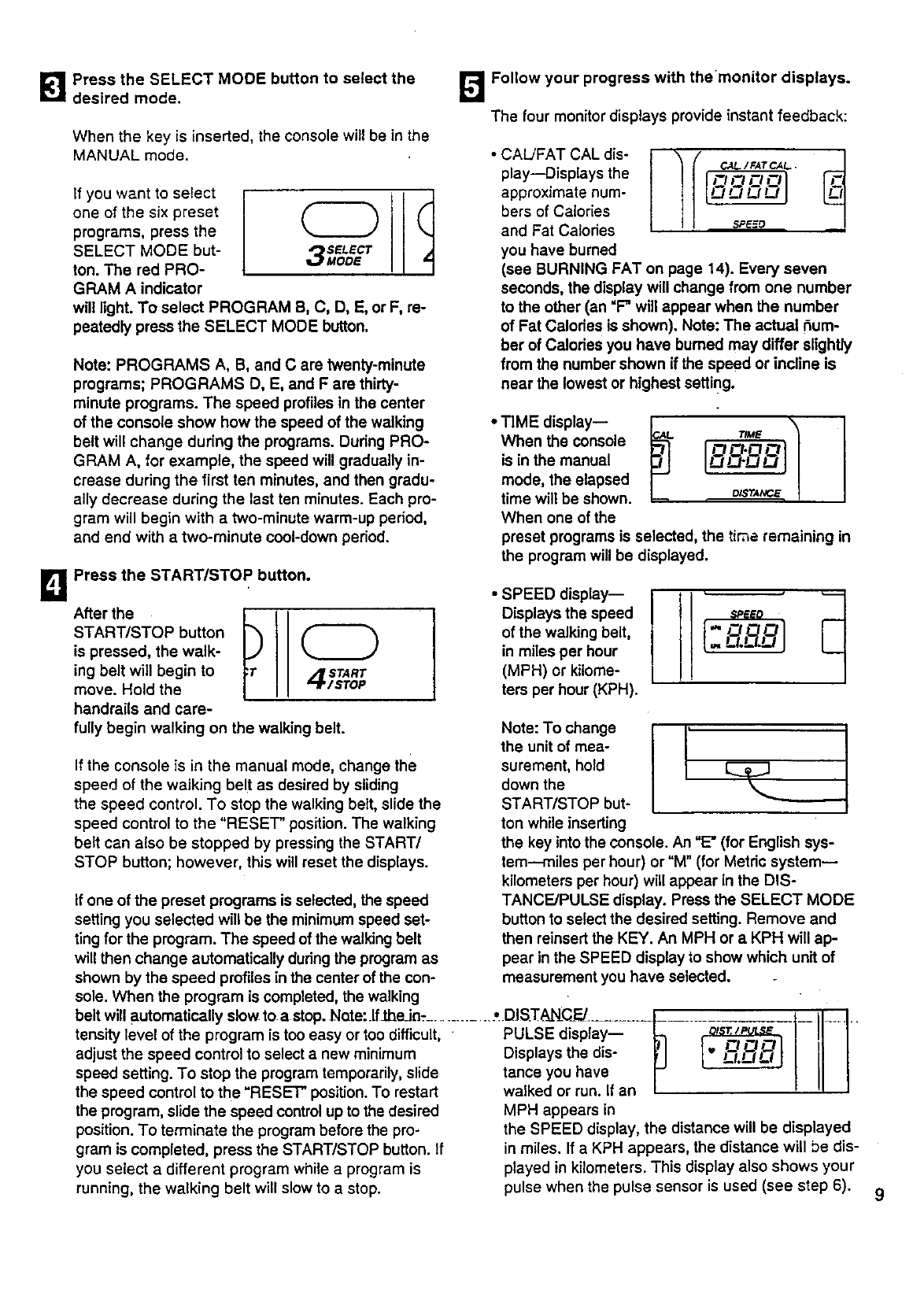
[_1 Press the SELECT MODE button to select the L_ Follow your progress with themonitor displays.
desired mode.
a
When the key is inserted, the console will be in the
MANUAL mode.
if you want to select
one of the six preset
programs, press the
SELECT MODE but-
ton. The red PRO-
GRAM A indicator
SELECT
MODE ,
will light. To select PROGRAM B, C, D, E, or F, re-
peatedly press the SELECT MODE button.
Note: PROGRAMS A, B, and C are twenty-minute
programs; PROGRAMS D, E, and F are thirty-
minute programs. The speed profiles in the center
of the console show how the speed of the walking
belt will change during the programs. Dudng PRO-
GRAM A, for example, the speed will gradually in-
crease during the first ten minutes, and then gradu-
ally decrease during the last ten minutes. Each pro-
gram will begin with atwo-minute warm-up period,
and end with a two-minute cool-down period.
Press the START/STOP button.
After the I
START/STOP button
is pressed, the walk-
ing belt will begin to
move. Hold the
handrails and care-
START
/STOP
fully begin walking on the walking belt.
If the console is in the manual mode, change the
speed of the walking belt as desired by sliding
the speed control. To stop the walking belt, slide the
speed control to the "RESET" position. The walking
belt can also be stopped by pressing the START/
STOP button; however, this will reset the displays.
The four monitor displays provide instant feedback:
•CAL/FAT CAL dis-
play--Displays the
approximate num-
bers of Calories
and Fat Calodes
you have burned
(see BURNING FAT on page 14). Every seven
seconds, the display will change from one number
to the other (an "F" will appear when the number
of Fat Calories is shown). Note: The actual r_um-
ber of Calories you have burned may differ slightly
from the number shown if the speed or incline is
near the lowest or highest setting.
•TIME display--
When the console
is in the manual
mode, the elapsed
time will be shown.
When one of the
preset programs is selected, the time remaining in
the program will be displayed.
• SPEED display--
Displays the speed
of the walking belt,
in miles per hour
(MPH) or kilome-
ters per hour (KPH).
Note: To change
the unit of mea-
surement, hold
down the
START/STOP but-
ton while inserting
If one of the preset programs is selected, the speed
setting you selected will be the minimum speed set-
ting for the program. The speed of the walking belt
will then change automatically duringthe program as
shown by the speed profiles in the center of the con-
sole. When the program is completed, the walking
belt will automatically slow to a stop. Note:.lfibe_Jn_.............. _DISTA_N_CFJ....... -t
tensity level of the program is too easy or too difficult, PULSE display-- IT1
adjust the speed control to select anew minimum Displays the dis- _;I
speed setting. To stop the program temporarily, slide tance you have i-"
the speed control to the "RESET" position. To restart walked or run. If an /
the program, slide the speed control up to the desired MPH appears in
position. To terminate the program before the pro-
gram is completed, press the START/STOP button. If
you select a different program while a program is
running, the walking belt will slow to a stop.
the key into the console. An "15"(for English sys-
tem---rniles per hour) or "M" (for Metric system--
kilometers per hour) will appear in the DIS-
TANCE/PULSE display. Press the SELECT MODE
button to select the desired setting. Remove and
then reinsert the KEY. An MPH or a KPH will ap-
pear in the SPEED display to show which unit of
measurement you have selected.
the SPEED display, the distance will be displayed
in miles. If a KPH appears, the distance will be dis-
played in kilometers. This display also shows your
pulse when the pulse sensor is used (see step 6).
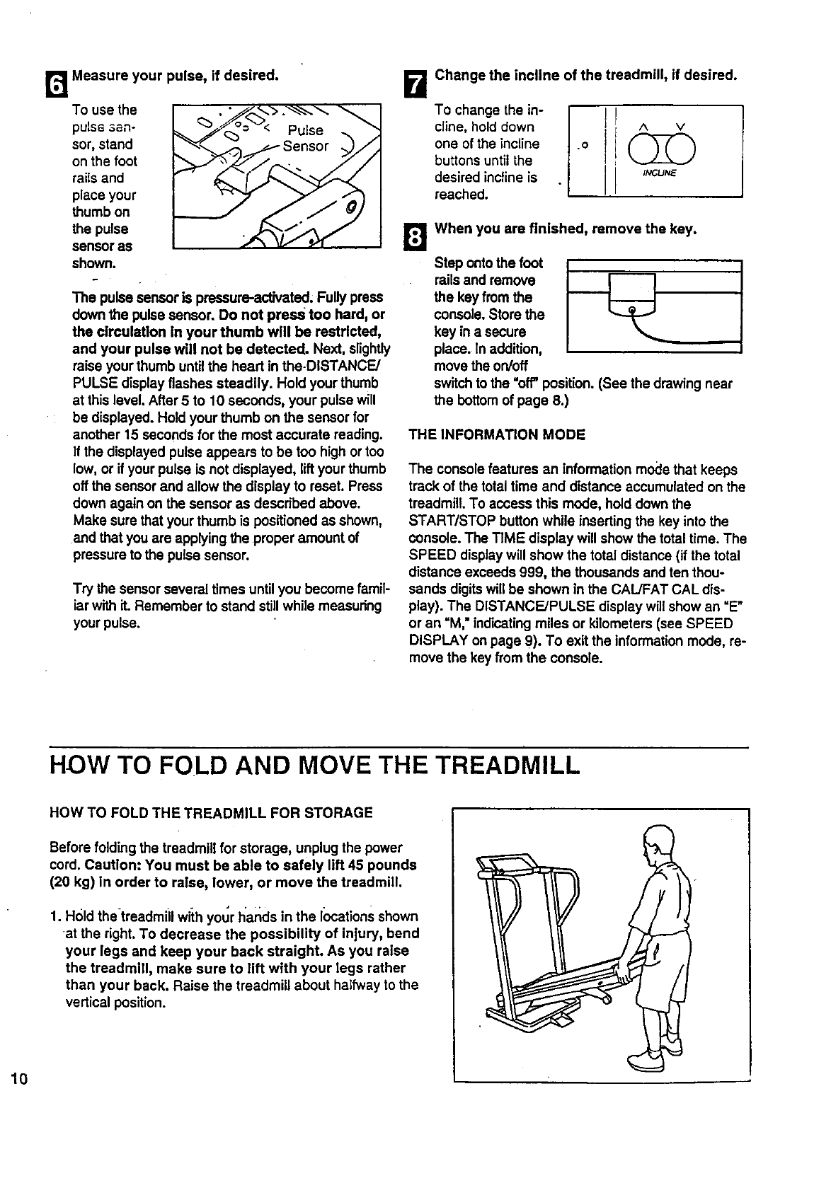
r_ Measure your pulse, if desired.
To use the
puls6 3an-
sor, stand
on the foot
rails and
place your
thumb on
the pulse
sensor as
shown.
The pulse sensor is pressure-activated, Fully press
down the pulse sensor. Do not press too hard, or
the clrculaUon In your thumb will be restdcted,
and your pulse will not be detected. Next, slightly
raise your thumb untilthe heart in the-DISTANCE/
PULSE displayflashes steadily. Hold your thumb
at this level. After 5 to 10 seconds, your pulse will
be displayed. Hold your thumb on the sensor for
another 15 seconds for the most accurate reading.
If the displayed pulse appears to be too high or too
low, or if your pulse is not displayed, liftyour thumb
off the sensor and allow the display to reset. Press
down again on the sensor as described above.
Make sure that your thumb is positioned as shown,
and that you are applying the proper amount of
pressure to the pulse sensor.
Try the sensor several times untilyou become famil-
iarwith it. Remember to stand stillwhile measuring
your pulse.
B Change the incline of the treadmill, if desired.
To change the in-
cline, hold down
one of the incline
buttons untilthe
desired incline is
reached.
AV
INCUNE
[] When you are finished, remove the key.
Step onto the foot
rails and remove
the key from the
console. Store the
key in a secure
place. In addition,
move the on/off
switchto the =off" position. (See the drawing near
the bottomof page 8.)
I
I
THE INFORMATION MODE
The console features an information mode that keeps
track of the total time and distance accumulated on the
treadmill. To access this mode, hold down the
START/STOP button while insertingthe key into the
console. The TIME display will show the total time. The
SPEED displaywill show the total distance (if the total
distance exceeds 999, the thousands and ten thou-
sands digitswill be shown in the CAUFAT CAL dis-
play). The DISTANCE/PULSE display will show an =E"
or an =M," indicating miles or kilometers (see SPEED
DISPLAY on page 9). To exit the information mode, re-
move the key from the console.
HOW TO FOLD AND MOVE THE TREADMILL
HOW TO FOLD THE TREADMILL FOR STORAGE
Before folding the treadmill for storage, unplug the power
cord. Caution: You must be able to safely lift 45 pounds
(20 kg) In order to raise, lower, or move the treadmill.
1. Hold thetreadmiil widthyour Ilands in the locations shown
at the right. To decrease the possibility of injury, bend
your legs and keep your back straight. As you raise
the treadmill, make sure to lift with your legs rather
than your back. Raise the treadmill about halfway to the
vertical position.
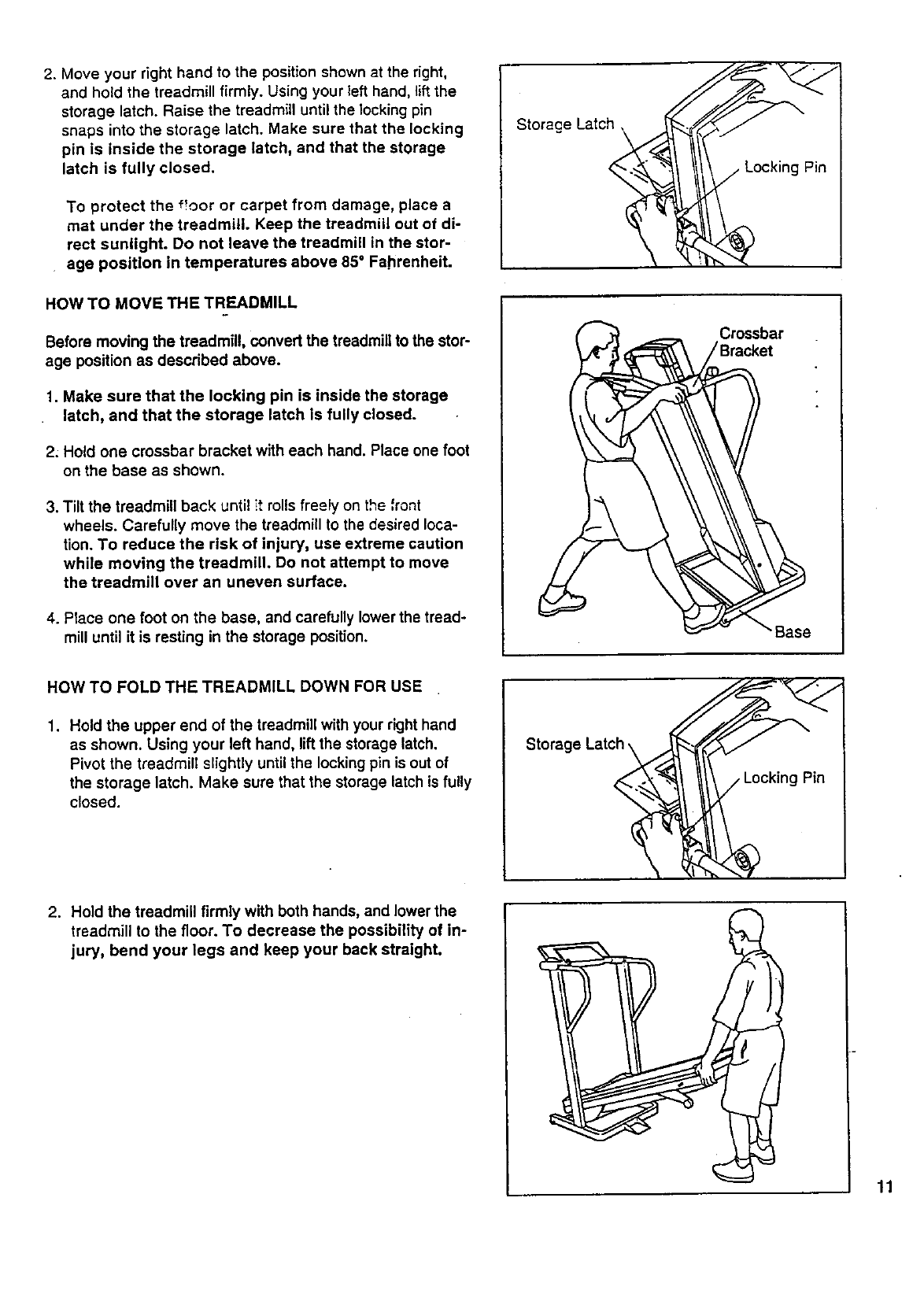
2. Move your right hand to the position shown at the right,
and hold the treadmill firmly. Using your left hand, lift the
storage latch. Raise the treadmill until the locking pin
snaps into the storage latch. Make sure that the locking
pin is inside the storage latch, and that the storage
latch is fully closed.
To protect the f!oor or carpet from damage, place a
mat under the treadmill. Keep the treadmill out of di-
rect sunlight. Do not leave the treadmill in the stor-
age position in temperatures above 85°Fahrenheit.
Storage Latch,
HOW TO MOVE THE TREADMILL
Before moving the treadmill, convert the treadmill to the stor-
age position as described above.
1. Make sure that the locking pin is inside the storage
latch, and that the storage latch is fully closed.
2: Hold one crossbar bracket with each hand. Place one foot
on the base as shown.
3. Tilt the treadmill back until it rolls freely on the front
wheels. Carefully move the treadmill to the desired loca-
tion. To reduce the risk of injury, use extreme caution
while moving the treadmill. Do not attempt to move
the treadmill over an uneven surface.
4. Place one foot on the base, and carefully lower the tread-
mill until it is resting in the storage position.
HOW TO FOLD THE TREADMILL DOWN FOR USE
1. Hold the upper end of the treadmill with your right hand
as shown. Using your left hand, lift the storage latch.
Pivot the treadmill slightly until the locking pin is out of
the storage latch. Make sure that the storage latch is fully
closed.
Storage Latch \
2. Hold the treadmill firmly with both hands, and lower the
treadmill to the floor. To decrease the possibility of in-
jury, bend your legs and keep your back straight.
11
TROUBLE-SHOOTING AND STORAGE
Most treadmill problems can be solved by following the simple steps below. Find the symptom that ap-
plies, and follow the steps listed. If further assistance is needed, call our toll-free HELPLINE at 1-800-736-
6879, Monday through Saturday, 7 a.m. until 7 p.m. Central Time (excluding holidays).
1. SYMPTOM: THE POWER DOES NOT TURN ON
a. Make sure that the power cord is plugged into a surge protector, and that the surge protector is plugged into
a properly grounded outlet. (See HOW TO PLUG IN THE POWER CORD on page 7.) Use only a UL-listed
surge protector, rated at 15 amps, with a 14-gauge cord of five feet or less in length.
b. After the power cord has been plugged in, make sure that the key is fully inserted into the console. Vadous
indicators on the console should light. (See step 1 page 8.)
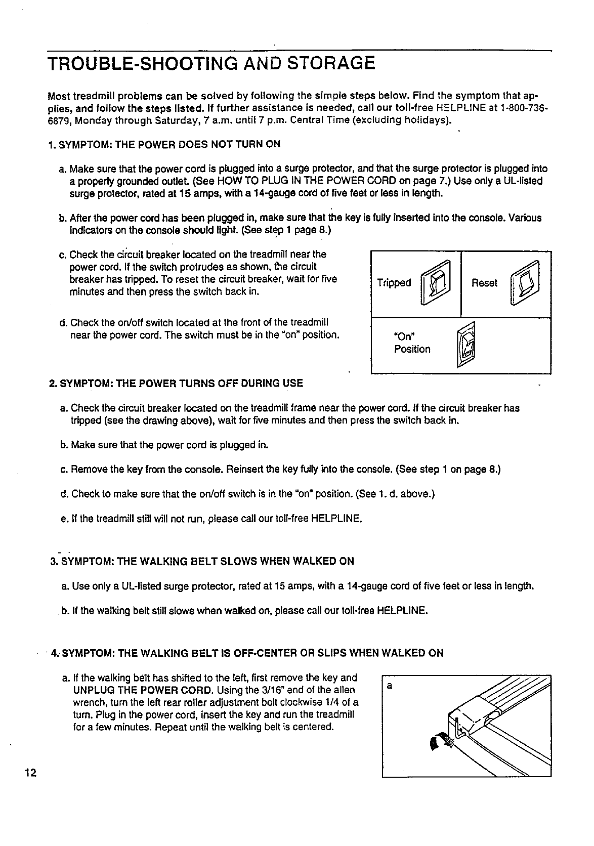
c. Check the circuit breaker located on the treadmill near the
power cord. If the switch protrudes as shown, the circuit
breaker has tripped. To reset the circuit breaker, wait for five
minutes and then press the switch back in.
d. Check the on/off switch located at the front of the treadmill
near the power cord. The switch must be in the "on" position.
Tripped Reset
"On" "_
Position
2. SYMPTOM" THE POWER TURNS OFF DURING USE
a. Check the circuitbreaker located on the treadmill frame near the power cord. If the circuit breaker has
tripped (see the drawing above), wait for five minutes and then press the switch back in.
b. Make sure that the power cord is plugged in.
c. Remove the key from the console. Reinsert the key fully into the console. (See step 1on page 8.)
d. Check to make sure that the on/off switch is in the =on" position. (See 1. d. above.)
e. If the treadmill still will not run, please call our toll-free HELPLINE.
3. SYMPTOM: THE WALKING BELT SLOWS WHEN WALKED ON
a. Use only aUL-listed surge protector, rated at 15 amps, with a 14-gauge cord of five feet or less in length.
b. If the walking belt still slows when walked on, please call our toll-free HELPLINE.
12
4..SYMPTOM: THE WALKING BELT IS OFF-CENTER OR SLIPS WHEN WALKED ON
a. If the walking belt has shifted to the left, first remove the key and
UNPLUG THE POWER CORD. Using the 3/16" end of the allen
wrench, turn the left rear roller adjustment bolt clockwise 1/4 of a
turn. Plug in the power cord, insert the key and run the treadmill
for a few minutes. Repeat until the walking belt is centered.
a

b. If the walking be!t has shifted to the right, first remove the key
and UNPLUG THE POWER CORD. Using the 3/16" end of the
allen wrench, turn the left rear roller adjustment bolt counter-
clockwise 1/4 of a turn. Plug in the power cord, insert the key
and run the treadmill for a few minutes. Repeat until the walking
belt is centered.
13
CONDITIONING GUIDELINES
The following guidelines will help you to plan your ex-
ercise program. Remember--these are general guide-
lines. For more detailed information about exercise,
obtain areputable book or consult your physician.
EXERCISE iNTENSITY
Whether you want to bum fat, strengthen your cardio-
vascular system, or increase your athletic perfor-
mance, you can tailor your exercise to your specific
goals. The key to achieving the desired results is to ex-
ercise with the proper intensity.
Burning Fat
To bum fat effectively, you must exercise at arelatively
low intensitylevel for a sustained period of time.
During the first few minutes of exemise, your body
uses easily accessible carbohydrate calories for en-
ergy. Only after the first few minutes of exercise does
your body begin to use stored fat calories for energy.
If your goal is to bum fat, set the speed control on the
consoleto FAT BURN to help you maintain the proper
intensitylevel. (See pages 8 and 9.)
Aerobic Exercise
If your goal is to strengthen your cardiovascular sys-
tem, your exercise must be "aerobic." Aerobic exercise
is activitythat requires large amounts of oxygen for
prolongedpedods of time. This increases the demand
or_the heart to pump blood to themuscles, and on the
lungsto oxygenate the blood. The proper intensity
level for aerobic exercise can be found by using your
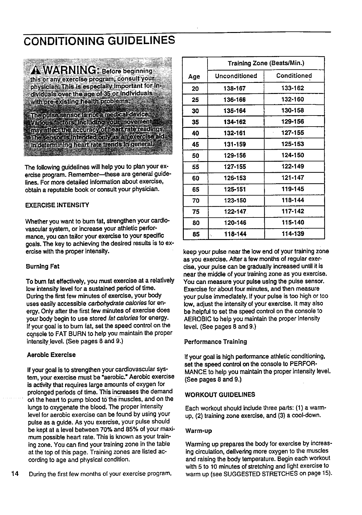
pulse as a guide. As you exercise, your pulse should
be kept at a level between 70% and 85% of your maxi-
mum possible heart rate. This is known as your train-
ing zone. You can find your training zone in the table
at the top of this page. Training zones are listed ac-
cordingto age and physical condition.
14 During the first few months of your exercise program,
Training Zone (Beats/Min.)
Age Unconditioned
20 138-167
25 136-166
30 135-164
35 134-162
40 132-161
•45 131-159
50 129-156
55 127-155
60 126-153
65 125-151
7O 123-150
75 122-147
80 120-146
85 118-144
Conditioned
133-162
132-160
130-158
129-156
127-155
125-153
124-150
122-149
121-147
119-145
118-144
117-142
115-140
114-139
keep your pulse near the low end of your training zone
as you exercise. After a few months of regular exer-
cise, your pulse can be gradually increased untilit is
near the middle of your trainingzone as you exercise.
You can measure your pulse using the pulse sensor.
Exercise for about four minutes, and then measure
your pulse immediately. If your pulse is too high or too
low, adjust the intensityof your exercise. It may also
be helpful to set the speed control on the console to
AEROBIC to help you maintainthe proper intensity
level. (See pages 8 and 9.)
Performance Training
If your goal is high performance athletic conditioning,
set the speed control on the console to PERFOR-
MANCE to help you maintain the proper intensity level.
(See pages 8 and 9.)
WORKOUT GUIDELINES
Each workout should include three pads: (1) awarm-
up, (2) training zone exercise, and (3) a cool-down.
Warm-up
Warming up prepares the body for exercise by increas-
ing circulation, delivering more oxygen to the muscles
and raising the body temperature. Begin each workout
with 5 to 10 minutes of stretching and light exercise to
warm up (see SUGGESTED STRETCHES on page 15).
T,_aining Zone Exercise
After warming up, increase the intensity of your exer-
cise untilyour pulse is in your training zone for 20 to
60 minutes. (During the first few weeks of your exer-.
cise program, do not keep your pulse in your training
zone for longer than 20 minutes.) Breathe regularly
and deeply as you exercise-never hold your breath.
Cool-down
Finish each workout with 5 to 10 minutes of stretching
to cool down. This will increase the flexibility of your
muscles and will help to prevent post-exercise problems.
Exercise Frequency
To maintain or improve your condition, complete three
workouts each week, with at least one day of rest be-
tween workouts. After a few months, you may com-
plete up to five workouts each wee_:if desired.
The key to success is to make exercise a regular and
enjoyable part of your everyday life.
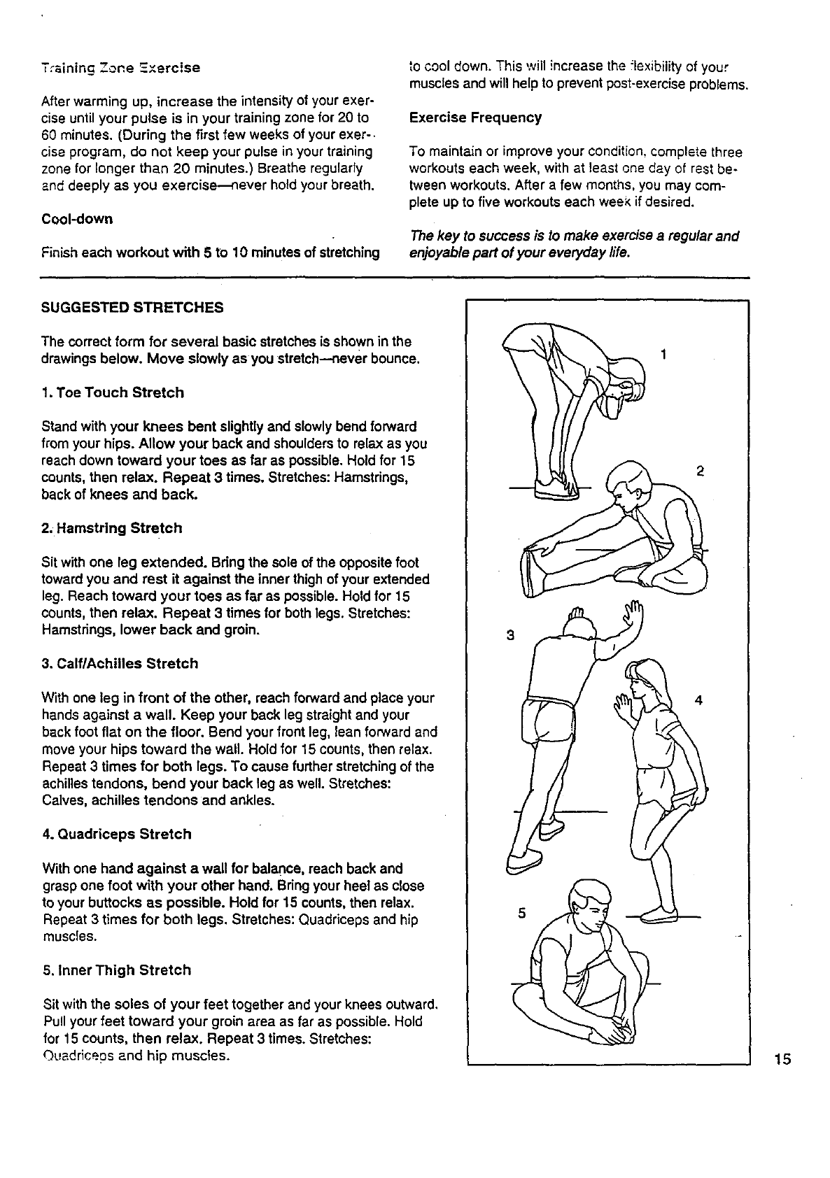
SUGGESTED STRETCHES
The correct form for several basic stretches is shown in the
drawings below. Move slowly as you stretch--never bounce.
1. Toe Touch Stretch
Stand with your knees bent slightly and slowly bend forward
from your hips. Allow your back and shoulders to relax as you
reach down toward your toes as far as possible. Hold for 15
counts, then relax. Repeat 3 times. Stretches: Hamstrings,
back of knees and back.
2. Hamstring Stretch
Sit with one leg extended. Bdng the sole of the opposite foot
toward you and rest it against the inner thigh of your extended
leg. Reach toward your toes as far as possible. Hold for 15
counts, then relax. Repeat 3 times for both legs. Stretches:
Hamstrings, lower back and groin.
3, Calf/Achilles Stretch
With one leg in front of the other, reach forward and place your
hands against a wall. Keep your back leg straight and your
back foot flat on the floor. Bend your front leg, lean forward and
move your hips toward the wall. Hold for 15 counts, then relax.
Repeat 3 times for both legs. To cause further stretching of the
achilles tendons, bend your back leg as well. Stretches:
Calves, achilles tendons and ankles.
4. Quadriceps Stretch
With one hand against a wall for balance, reach back and
grasp one foot with your other hand. Bring your heel as close
to your buttocks as possible. Hold for 15 counts, then relax.
Repeat 3 times for both legs. Stretches: Quadriceps and hip
muscles.
5. Inner Thigh Stretch
Sit with the soles of your feet together and your knees outward,
Pull your feet toward your groin area as far as possible. Hold
for 15 counts, then relax. Repeat 3 times. Stretches:
Quedriceps and hip muscles.
3
2
4
15

SEARS
Model No. 831.297643
QUESTIONS?
If you find that:
• you need help assembling or
operating the PROFORM* 580sl
treadmill
•a part Is missing
• or you need to schedule repair
service
call our toll-free HELPLINE
1-800-736-6879
Monday-Saturday, 7 am-7 pm
Central Time (excluding holidays)
REPLACEMENT
PARTS
If parts become worn and need
to be replaced, call the following
toll-free number
1-800-FON-PART
(1-800-366-7278)
The model number and serial number of your PROFORM ®580si
treadmill are listed on a decal attached to the frame. See the front
cover of this manual to find the location of the decal.
All replacement parts are available for immediate purchase or
special orderwhen you visit your nearest SEARS Service Center.
To request serviceor to order parts by telephone, call the toU-free
numbers listed at the left.
When requestinghelp or service, or ordering pads, please be pre-
pared to providethe following information:
• The NAME OF THE PRODUGT (PROFORM =580si treadmill)
• The MODEL NUMBER OF THE PRODUCT (831.297643)
•The PART NUMBER OF THE PART (see the EXPLODED
DRAWING and PART LIST attached to the center of this manual)
•The DESCRIPTION OF THE PART (see the EXPLODED DRAW-
ING and PART LIST attached to the center of this manual)
IFULL 90 DAY WARRANTY I
For 90 days from the date of purchase, if failure occurs due to defect in material or workmanship in this
SEARS TREADMILL EXERCISER, contact the nearest SEARS Service Center throughout the United
States and SEARS will repair or replace the TREADMILL EXERCISER, free of charge.
This warranty does not apply when the TREADMILL EXERCISER is used commercially or for rental pur-
poses.
This warranty gives you specific legal rights, and you may also have other rights which vary from state
to state.
SEARS, ROEBUCK AND CO., DEPT. 817WA, HOFFMAN ESTATES, IL 60179
•Part No. 129598 F00445-C R0396A Printed in USA © 1996 Sears, Roebuck and Co.
