Proform Pfex014140 Le Tour De France Bike Users Manual
2015-04-14
: Proform Proform-Pfex014140-Le-Tour-De-France-Bike-Users-Manual-701116 proform-pfex014140-le-tour-de-france-bike-users-manual-701116 proform pdf
Open the PDF directly: View PDF ![]() .
.
Page Count: 32
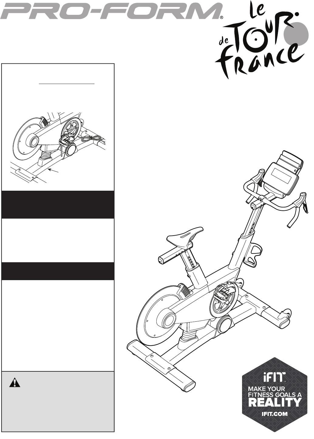
USER’S MANUAL
CAUTION
Read all precautions and instruc-
tions in this manual before using
this equipment. Keep this manual
for future reference.
Model No. PFEX01414.0
Serial No.
Write the serial number in the space
above for reference.
www.proform.com
Serial Number
Decal (under frame)
To register your product and
activate your warranty today,
go to www.proformservice.com/
registration.
For service at any time, go to
www.proformservice.com.
Or call 1-877-660-1168
Mon.–Fri. 6 a.m.–6 p.m. MT
Sat. 8 a.m.–12 p.m. MT
Please do not contact the store.
ACTIVATE YOUR
WARRANTY
CUSTOMER CARE
2
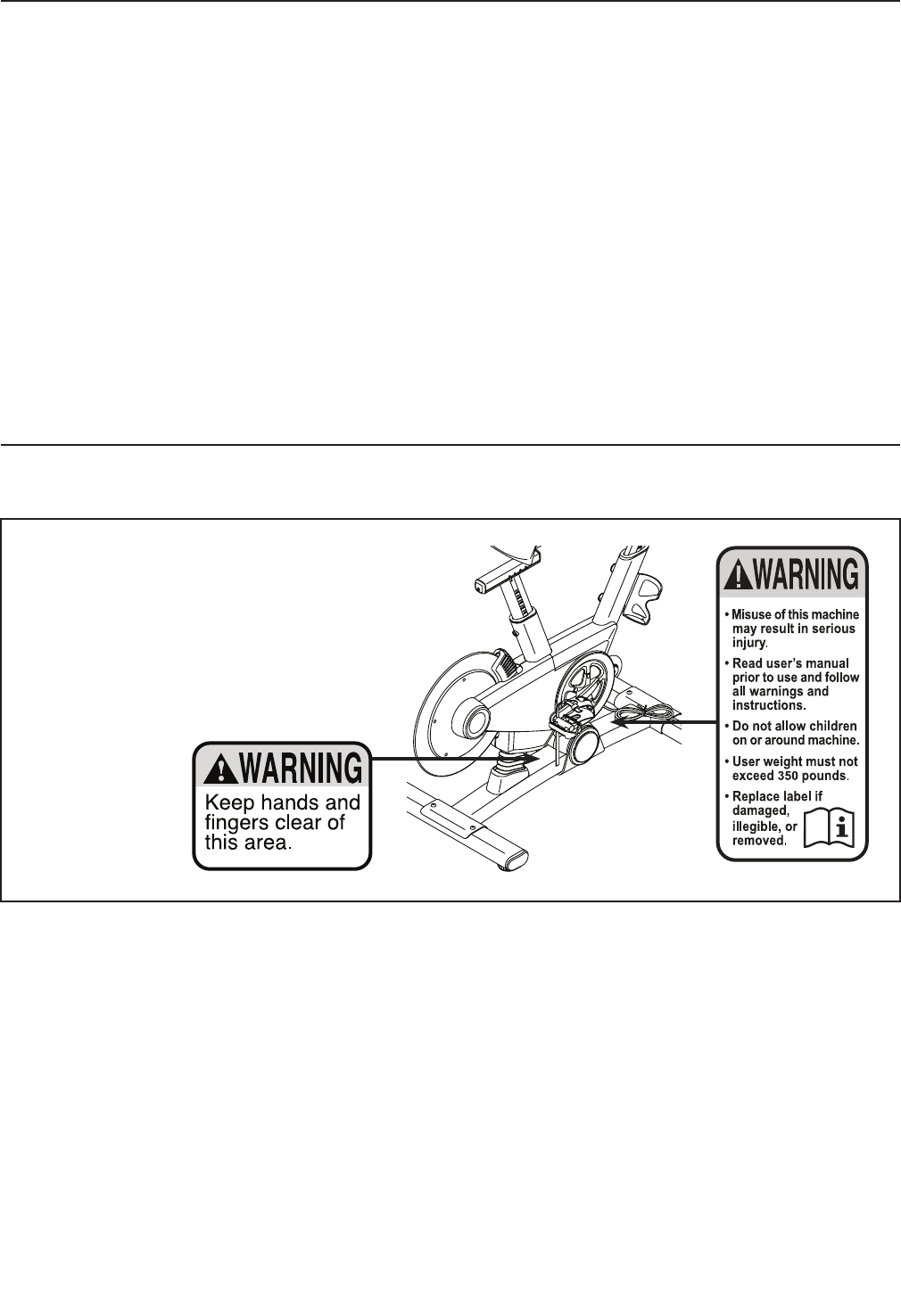
This drawing shows the location(s) of the
warning decal(s). If a decal is missing or
illegible, see the front cover of this manual
and request a free replacement decal.
Apply the decal in the location shown.
Note: The decal(s) may not be shown at
actual size.
WARNING DECAL PLACEMENT . . . . . . . . . . . . . . . . . . . . . . . . . . . . . . . . . . . . . . . . . . . . . . . . . . . . . . . . . . . . . . .2
IMPORTANT PRECAUTIONS . . . . . . . . . . . . . . . . . . . . . . . . . . . . . . . . . . . . . . . . . . . . . . . . . . . . . . . . . . . . . . . . . .3
BEFORE YOU BEGIN. . . . . . . . . . . . . . . . . . . . . . . . . . . . . . . . . . . . . . . . . . . . . . . . . . . . . . . . . . . . . . . . . . . . . . . .6
PART IDENTIFICATION CHART. . . . . . . . . . . . . . . . . . . . . . . . . . . . . . . . . . . . . . . . . . . . . . . . . . . . . . . . . . . . . . . .7
ASSEMBLY . . . . . . . . . . . . . . . . . . . . . . . . . . . . . . . . . . . . . . . . . . . . . . . . . . . . . . . . . . . . . . . . . . . . . . . . . . . . . . . .8
HOW TO USE THE TRAINING BIKE . . . . . . . . . . . . . . . . . . . . . . . . . . . . . . . . . . . . . . . . . . . . . . . . . . . . . . . . . . .13
FCC INFORMATION . . . . . . . . . . . . . . . . . . . . . . . . . . . . . . . . . . . . . . . . . . . . . . . . . . . . . . . . . . . . . . . . . . . . . . . .26
MAINTENANCE AND TROUBLESHOOTING . . . . . . . . . . . . . . . . . . . . . . . . . . . . . . . . . . . . . . . . . . . . . . . . . . . . .27
EXERCISE GUIDELINES . . . . . . . . . . . . . . . . . . . . . . . . . . . . . . . . . . . . . . . . . . . . . . . . . . . . . . . . . . . . . . . . . . . .28
PART LIST. . . . . . . . . . . . . . . . . . . . . . . . . . . . . . . . . . . . . . . . . . . . . . . . . . . . . . . . . . . . . . . . . . . . . . . . . . . . . . . .29
EXPLODED DRAWING. . . . . . . . . . . . . . . . . . . . . . . . . . . . . . . . . . . . . . . . . . . . . . . . . . . . . . . . . . . . . . . . . . . . . .31
ORDERING REPLACEMENT PARTS. . . . . . . . . . . . . . . . . . . . . . . . . . . . . . . . . . . . . . . . . . . . . . . . . . . Back Cover
LIMITED WARRANTY. . . . . . . . . . . . . . . . . . . . . . . . . . . . . . . . . . . . . . . . . . . . . . . . . . . . . . . . . . . . . . . Back Cover
WARNING DECAL PLACEMENT
TABLE OF CONTENTS
PROFORM is a registered trademark of ICON Health & Fitness, Inc. IFIT is a registered trademark of ICON
Health & Fitness, Inc. LE TOUR DE FRANCE is a registered trademark of Société du Tour de France. The
BLUETOOTH® word mark and logos are registered trademarks of Bluetooth SIG, Inc. and are used under license.
Android is a trademark of Google Inc. Google Maps is a trademark of Google Inc. iPad is a trademark of Apple
Computer, Inc., registered in the U.S. and other countries. iPad® is not included. Wi-Fi is a registered trademark of
Wi-Fi Alliance.

3
IMPORTANT PRECAUTIONS
WARNING: To reduce the risk of burns, fire, electric shock, or injury to persons, read all
important precautions and instructions in this manual and all warnings on your training bike before
using your training bike. ICON assumes no responsibility for personal injury or property damage
sustained by or through the use of this product.
SAVE THESE INSTRUCTIONS
1. It is the responsibility of the owner to ensure
that all users of the training bike are ade-
quately informed of all precautions.
2. Before beginning any exercise program,
consult your physician. This is especially
important for persons over age 35 or per-
sons with pre-existing health problems.
3. Use the training bike only as described in
this manual.
4. The training bike is intended for home use
only. Do not use the training bike in a com-
mercial, rental, or institutional setting.
5. Keep the training bike indoors, away from
moisture and dust. Do not put the training
bike in a garage or covered patio, or near
water.
6. Place the training bike on a level surface with
at least 2 ft. (0.6 m) of clearance around the
training bike. To protect the floor or carpet
from damage, place a mat under the training
bike.
7. Inspect and properly tighten all parts regu-
larly. Replace any worn parts immediately.
8. Keep children under age 12 and pets away
from the training bike at all times.
9. When connecting the power cord, plug the
power cord into a grounded circuit.
10. Do not modify the power cord or use an
adapter to connect the power cord to an
improper receptacle. Keep the power cord
away from heated surfaces. Do not use an
extension cord.
11. Do not operate the training bike if the power
cord or plug is damaged, or if the training
bike is not working properly.
12. DANGER: Always unplug the power
cord and press the power switch to the off
position when the training bike is not in
use and before cleaning the training bike.
Servicing other than the procedures in this
manual should be performed by an autho-
rized service representative only.
13. Wear appropriate clothes while exercising;
do not wear loose clothes that could become
caught on the training bike. Always wear
athletic shoes for foot protection.
14. The training bike should not be used by per-
sons weighing more than 350 lbs. (159 kg).
15. Be careful when mounting and dismounting
the training bike.
16. Always keep your back straight while using
the training bike; do not arch your back.
17. Over exercising may result in serious injury
or death. If you feel faint, if you become short
of breath, or if you experience pain while
exercising, stop immediately and cool down.

4
5
all
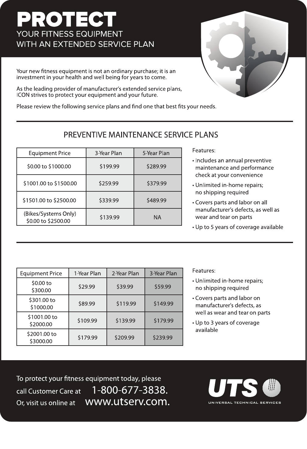
STANDARD SERVICE PLANS
6
Congratulations for selecting the revolutionary
PROFORM® LE TOUR DE FRANCE® training bike.
The LE TOUR DE FRANCE training bike is unlike any
ordinary exercise bike. With full adjustability, a Wi-Fi®
cycling console, an incline system that simulates actual
road terrain, and an array of other innovative features,
the LE TOUR DE FRANCE training bike is designed to
let you enjoy the outdoor cycling experience indoors.
For your benefit, read this manual carefully before
you use the training bike. If you have questions after
reading this manual, please see the front cover of this
manual. To help us assist you, note the product model
number and serial number before contacting us. The
model number and the location of the serial number
decal are shown on the front cover of this manual.
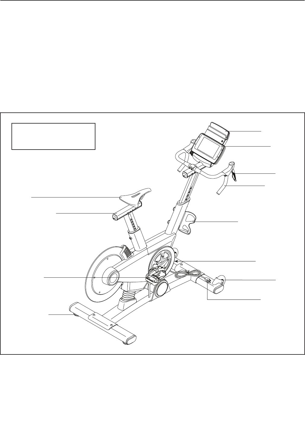
Before reading further, please familiarize yourself with
the parts that are labeled in the drawing below.
Saddle
Shifter
Saddle Carriage
Handlebar
Water Bottle Holder*
*Water bottle is not included
Wheel
Pedal/Strap
Console
iPad Holder
Leveling Foot
Power Switch
Power Cord
Length: 5 ft. 4 in. (163 cm)
Width: 2 ft. 1 in. (64 cm)
BEFORE YOU BEGIN
7
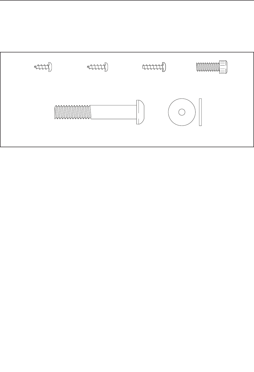
M6 x 16mm
Screw (110)–4
M4 x 10mm
Screw (116)–2
M10 x 58mm
Screw (74)–4
M4 Washer
(54)–1
M4 x 14mm
Screw (117)–1
M4 x 12mm
Screw (111)–4
PART IDENTIFICATION CHART
Use the drawings below to identify the small parts needed for assembly. The number in parentheses below each
drawing is the key number of the part, from the PART LIST near the end of this manual. The number following the
key number is the quantity needed for assembly. Note: If a part is not in the hardware kit, check to see if it
has been preassembled. Extra parts may be included.
8
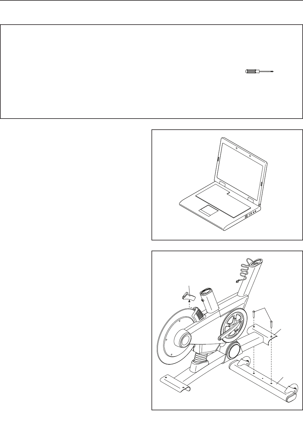
2
22
74
Shipping
Insert
1
2. Remove and discard the indicated shipping
insert. If there are shipping screws in the
Front Stabilizer (22), remove and discard
them.
Attach the Front Stabilizer (22) to the Base (1)
with two M10 x 58mm Screws (74).
ASSEMBLY
• To hire an authorized service technician to
assemble the training bike, call 1-800-445-2480.
• Assembly requires two persons.
• Place all parts in a cleared area and remove the
packing materials. Do not dispose of the packing
materials until you fi nish all assembly steps.
• Left parts are marked “L” or “Left” and right parts
are marked “R” or “Right.”
• To identify small parts, see page 7.
• In addition to the included tool(s), assembly
requires the following tools:
one Phillips screwdriver
Assembly may be easier if you have your own set
of wrenches. To avoid damaging parts, do not use
power tools.
1. Go to www.proformservice.com/registration
on your computer and register your product.
• activates your warranty
• saves you time if you ever need to contact
Customer Care
• allows us to notify you of upgrades and offers
Note: If you do not have Internet access, call
Customer Care (see the front cover of this
manual) and register your product.
1
9
2
3
Indicators
47
3
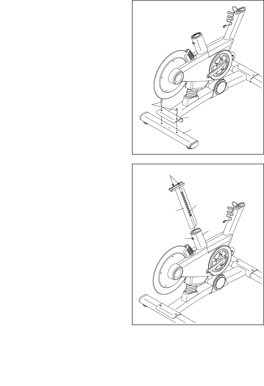
3. If there are shipping screws in the Rear
Stabilizer (23), remove and discard them.
Attach the Rear Stabilizer (23) to the Base (1)
with two M10 x 58mm Screws (74).
74
23
1
4. Using a plastic bag to keep your fingers clean,
apply some of the included grease to the sides
of the channel on the top of the Saddle Post (3).
Next, orient the Saddle Post (3) so that the
height indicators are on the side shown.
Loosen the indicated Adjustment Screw (47),
and insert the Saddle Post (3) into the Frame (2).
Move the Saddle Post (3) upward or downward
to the desired position, and then tighten the
Adjustment Screw (47).
4Grease
10
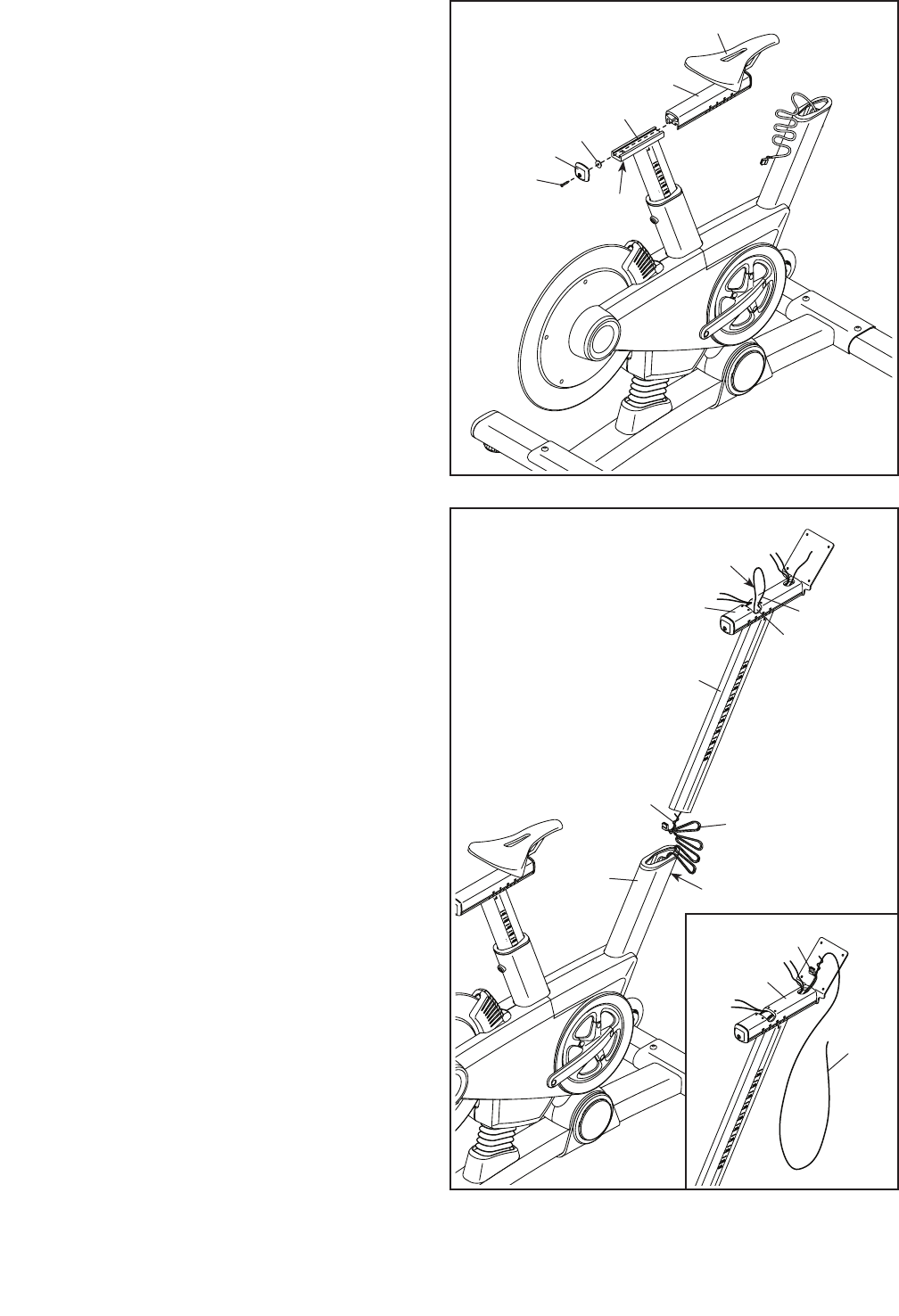
5
5. Tip: You can attach your own saddle to the
Saddle Carriage (4) if desired. Loosen the
attachment hardware (not shown) beneath the
Saddle (5), and remove the Saddle. Then, attach
your own saddle and retighten the attachment
hardware.
Orient the Saddle Carriage (4) as shown.
Loosen the indicated M8 x 15mm Round Head
Screw (115), and slide the Saddle Carriage (4)
into the Saddle Post (3).
Slide the Saddle Carriage (4) to the desired posi-
tion, and tighten the M8 x 15mm Round Head
Screw (115).
Then, attach an M4 Washer (54) and the
Carriage Cover (91) to the Saddle Carriage (4)
with an M4 x 14mm Screw (117).
3
4
5
117
115
54
91
6
6
2
68
105
47
Wire
Tie
Wire Tie
Access
Hole
Pull Here
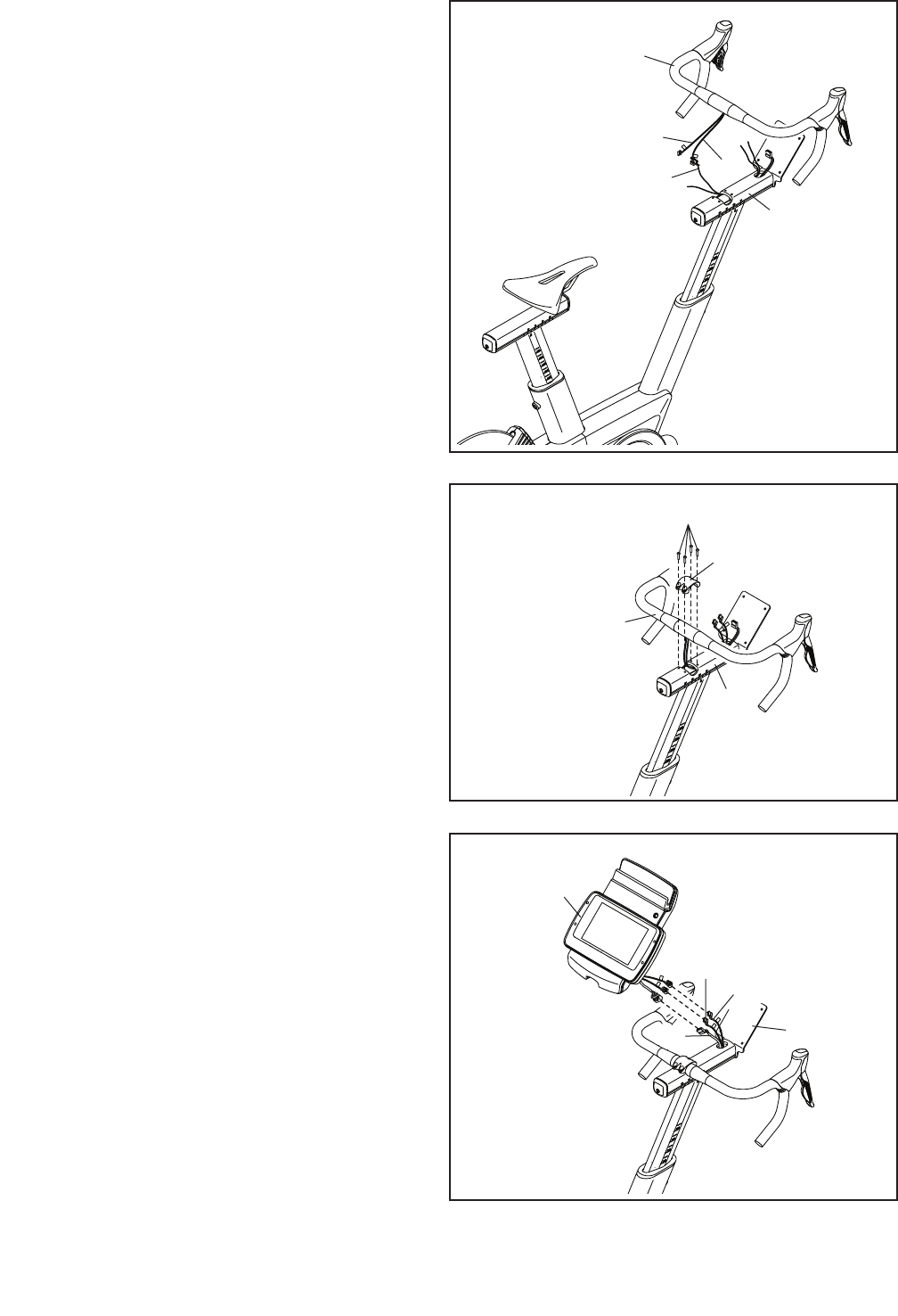
6. See step 8. If the Handlebar Clamp (28) and
four M6 x 16mm Screws (110) are preattached
to the Handlebar Carriage (105), remove them
and set them aside until step 8.
Have a second person hold the Handlebar Post
(6) near the Frame (2).
Locate the long wire tie in the Handlebar Post
(6). Tie the lower end of the long wire tie to the
Main Wire (68). Next, locate the same wire tie in
the access hole in the Handlebar Carriage (105).
Pull the wire tie upward until the end of the Main
Wire is in the access hole.
See the inset drawing. Next, pull the upper end
of the long wire tie until the Main Wire (68) is
routed through the Handlebar Carriage (105) as
shown. Then, untie and discard the long wire tie.
Tip: Avoid pinching the Main Wire (68).
Loosen the indicated Adjustment Screw (47),
and insert the Handlebar Post (6) into the
Frame (2).
Move the Handlebar Post (6) upward or down-
ward to the desired position, and tighten the
Adjustment Screw (47).
Avoid pinching the
Main Wire (68)
105
68
Wire
Tie
11
105
107
9
9
68
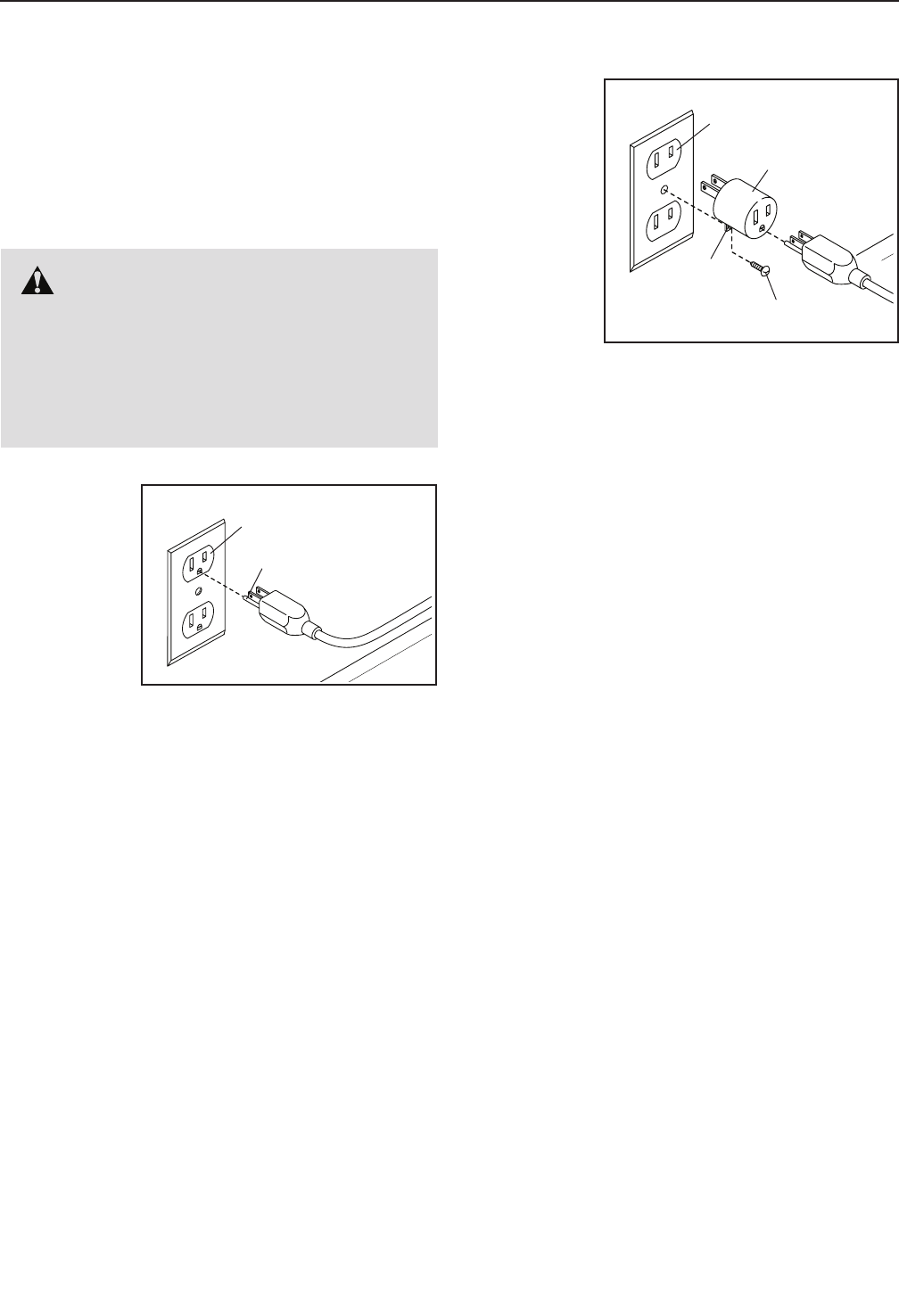
9. Have a second person hold the Console (9) near
the Handlebar Carriage (105).
Connect the console wires to the Main Wire (68)
and to the Extension Wires (107, 108); make
sure to connect the console wire that has an
“L” tag to the Extension Wire that has an “L”
tag, and connect the console wire that has an
“R” tag to the Extension Wire that has an “R”
tag.
Insert the excess wire into the Console (9).
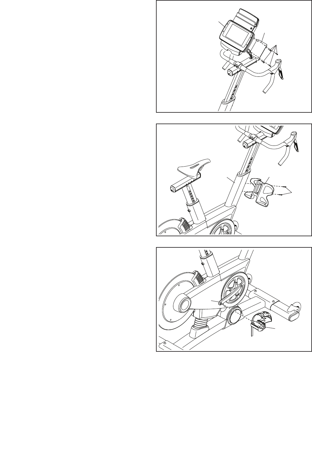
7. Have a second person hold the Handlebar (7)
near the Handlebar Carriage (105).
Locate one of the remaining wire ties in the
Handlebar Carriage (105). Tie the indicated end
of the wire tie to the Right Extension Wire (107).
Then, pull the other end of the wire tie until
the Right Extension Wire is routed through the
Handlebar Carriage. Then, untie and discard the
wire tie.
Route the Left Extension Wire (108) through
the Handlebar Carriage (105) in the same
way.
8. Tip: Avoid pinching the wires. Hold the
Handlebar (7) on the Handlebar Carriage (105),
and rotate the Handlebar to the desired angle;
make sure that the Handlebar is centered on
the Handlebar Carriage.
Attach the Handlebar (7) with the Handlebar
Clamp (28) and four M6 x 16mm Screws (110);
start all four Screws, and then tighten them.
7
8
7
7
110
28
105
105
108
107
Wire Tie
Avoid pinching
the wires
108
12
13. After the training bike is assembled, inspect it to make sure that it is assembled correctly and that it
functions properly. Make sure that all parts are properly tightened before you use the training bike.
Note: Extra parts may be included. Place a mat beneath the training bike to protect the floor.
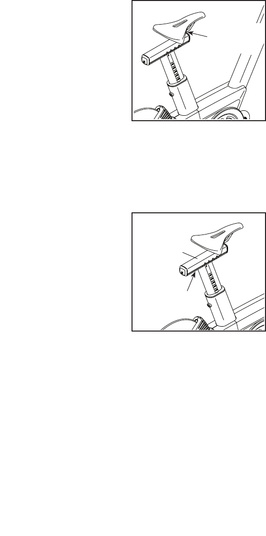
11. Attach the Tray (8) to the Frame (2) with two
M4 x 10mm Screws (116).
12. Tip: You can attach your own pedals if
desired.
Identify the Right Pedal (62).
Using the included flat wrench tool, firmly
tighten the Right Pedal (62) clockwise into the
Right Crank Arm (64).
Firmly tighten the Left Pedal (not shown)
counterclockwise into the Left Crank Arm (not
shown).
11
12
8
62
2
116
64
10
111
105
9
10. Tip: Avoid pinching the wires. Attach the
Console (9) to the Handlebar Carriage (105) with
four M4 x 12mm Screws (111).
Avoid pinching
the wires
13
HOW TO PLUG IN THE POWER CORD
This product must be grounded. If it should mal-
function or break down, grounding provides a path of
least resistance for electric current to reduce the risk
of electric shock. The power cord has a plug with a
grounding pin.
Plug the
power cord
into an
appropriate
outlet that
is properly
installed and
grounded in
accordance
with all local
codes and
ordinances. The outlet must be on a nominal 120-volt
circuit.
A temporary
adapter may
be used to
connect the
power cord
to a 2-pole
receptacle
as shown
at the right
if a properly
grounded
outlet is not
available.
The lug or wire extending from the adapter must
be connected with a metal screw to a permanent
ground such as a properly grounded outlet box cover.
Some 2-pole receptacle outlet box covers are not
grounded. Before using an adapter, contact a quali-
fied electrician to determine whether the outlet
box cover is grounded before using an adapter.
The temporary adapter should be used only until
a properly grounded outlet can be installed by a
qualified electrician.
HOW TO USE THE TRAINING BIKE
DANGER: Improper connection of
the power cord increases the risk of electric
shock. Do not modify the plug; if it will not fit
an outlet, have a proper outlet installed by a
qualified electrician. If you are unsure whether
the product is properly grounded, contact a
qualified electrician.
Grounded Outlet
2-pole Receptacle
Grounding Pin
Adapter
Lug
Metal Screw
14
FEATURES OF THE TRAINING BIKE
Measuring Watts
Each training bike is individually calibrated to measure
your power output and allow you to monitor your watts
and pedaling cadence directly on the console.
By monitoring your watts and pedaling cadence, you
can see how hard you are training and make sure that
you are challenging yourself and improving.
The Incline System
The training bike can incline and decline up to 20 per-
cent to realistically simulate outdoor terrain. When you
create maps of your actual training routes on iFit.com
(see the console instructions beginning on page 16
for more information), the training bike will automati-
cally incline and decline to match the terrain of your
training routes.
The Handlebar Shifters
The training bike allows you to shift gears just like
you do on your road bike. The right and left handlebar
shifters simulate front and rear derailleurs that you can
configure to match the gearing setup of your road bike
(see the console instructions beginning on page 16
for more information).
Pedaling Form Features
The training bike has multiple features to help you
develop correct pedaling form:
Freewheel—The training bike has a freewheel that
simulates a road bike rather than a fixed-drive spin
bike. This discourages you from letting your feet coast
through the top and bottom of your pedal stroke.
Flywheel—The flywheel on the training bike has the
correct inertia to allow you to pedal smoothly while
encouraging you to use good pedaling form.
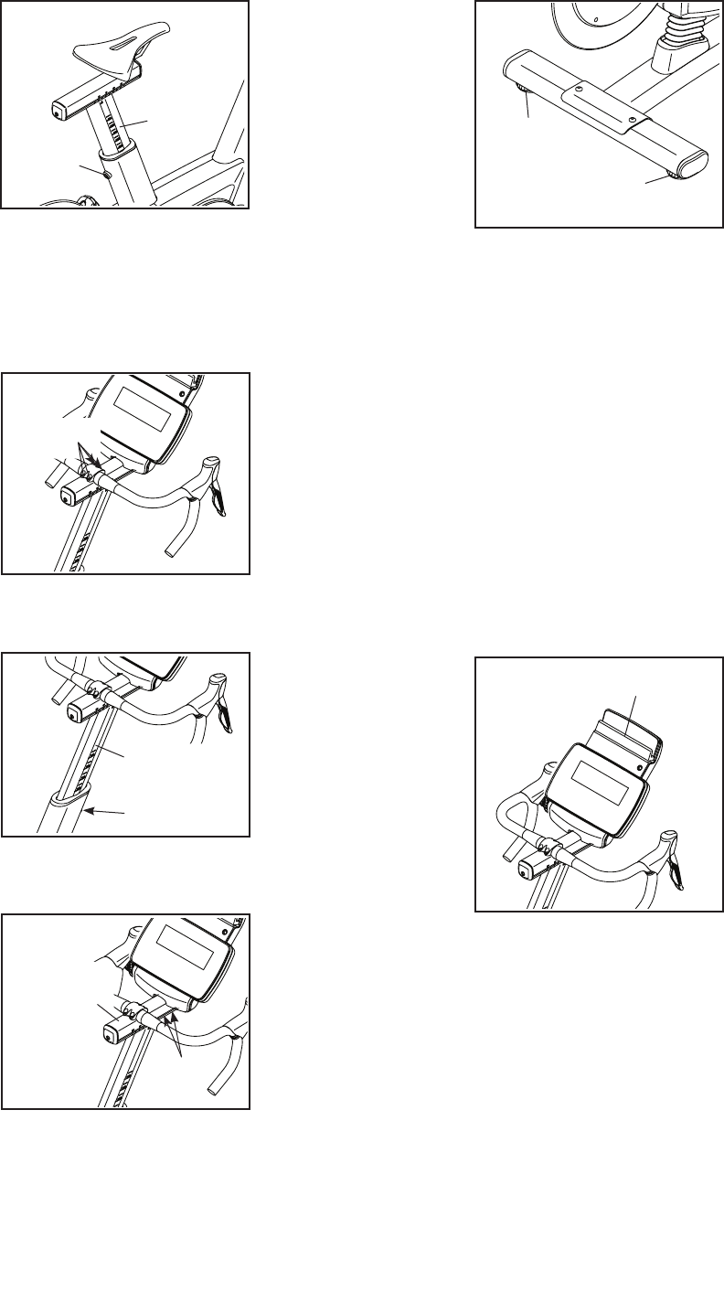
HOW TO ADJUST THE GEOMETRY OF THE
TRAINING BIKE
The training bike can be adjusted to match the geom-
etry of your road bike to promote correct form and to
ensure proper training of the muscles. Note: Make
adjustments in small increments, and then pedal
the training bike to test the adjustments.
How to Adjust the Angle of the Saddle
You can adjust the angle of the saddle to the posi-
tion that is most comfortable. You can also adjust the
saddle forward or backward for increased comfort or to
adjust the distance to the handlebar.
To adjust the
saddle, first loosen
the attachment
hardware beneath
the saddle a few
turns. Next, tilt the
saddle upward or
downward or slide
the saddle forward
or backward, Then,
retighten the attach-
ment hardware.
Note: You can remove the saddle and attach your
own saddle if desired.
How to Adjust the Saddle Carriage
To ad ju st t he p os i-
tion of the saddle
carriage, loosen the
adjustment screw,
move the saddle
carriage forward or
backward, and then
retighten the adjust-
ment screw.
Hardware
Saddle
Carriage
Screw
15
How to Adjust the Saddle Post
For effective train-
ing, the saddle
should be at the
proper height. As
you pedal, there
should be a slight
bend in your knees
when the pedals
are in the lowest
position. To adjust
the height of the
saddle post, loosen the adjustment screw, move the
saddle post upward or downward, and then retighten
the adjustment screw.
How to Adjust the Rotation of the Handlebar
To rotate the
handlebar to match
the position of the
handlebar on your
road bike, loosen
the indicated
screws, rotate the
handlebar, and
then retighten the
screws.
How to Adjust the Handlebar Post
To ad ju st t he h ei gh t
of the handlebar
post, loosen the
adjustment screw,
move the handle-
bar post upward
or downward, and
then retighten the
adjustment screw.
How to Adjust the Handlebar Carriage
To adjust the
position of the
handlebar carriage
to match your road
bike, loosen the
indicated screws,
move the handlebar
carriage forward
or backward, and
then retighten the
screws.
HOW TO LEVEL THE TRAINING BIKE
If the training bike
rocks slightly on
your floor during
use, turn one or
both of the level-
ing feet on the rear
stabilizer until the
rocking motion is
eliminated.
HOW TO USE THE PEDALS
To use the pedals, insert your shoes into the toe
cages, and pull the ends of the toe straps. To adjust
the toe straps, press and hold the tabs on the buckles,
adjust the toe straps to the desired position, and then
release the tabs.
Note: You can attach your own pedals to the training
bike if desired.
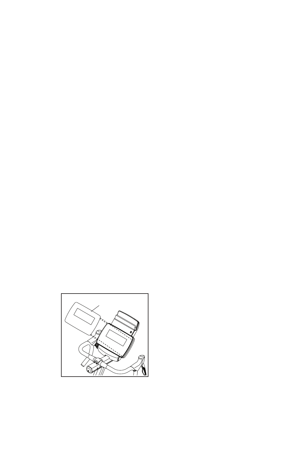
HOW TO USE THE IPAD HOLDER
IMPORTANT: The iPad® holder is designed for use
with most full-size iPads. Do not place an iPad mini
or any other electronic device or object in the iPad
holder.
To in se rt a n iP ad
into the iPad holder,
set the bottom edge
of the iPad in the
tray. Make sure
that the iPad is
firmly secured in
the iPad Holder.
Reverse these
actions to remove
the iPad from the
iPad Holder.
Screw
Saddle
Post
Screws
Screw
Handlebar
Post
Screws
Handlebar
Carriage
Leveling
Foot
Leveling
Foot
Tray
16
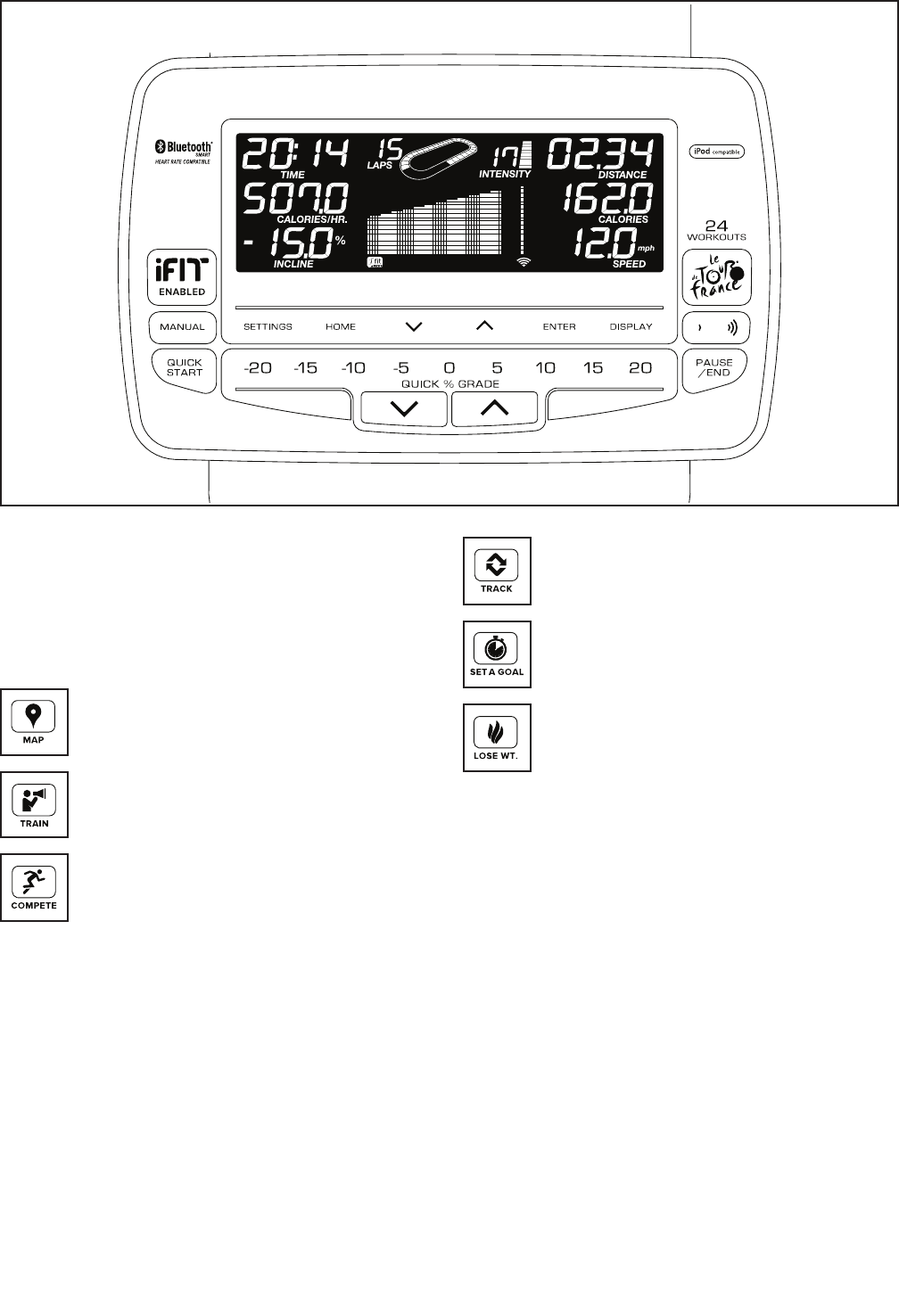
CONSOLE DIAGRAM
MAKE YOUR FITNESS GOALS A REALITY WITH
IFIT.COM
With your new iFit-compatible fitness equipment, you
can use an array of features on iFit.com to make your
fitness goals a reality:
Exercise anywhere in the world with
customizable Google Maps.
Download training workouts designed to
help you reach your personal goals.
Measure your progress by competing
against other users in the iFit community.
Upload your workout results to the iFit cloud
and track your accomplishments.
Set calorie, time, or distance goals for your
workouts.
Choose and download sets of weight-loss
workouts.
Go to iFit.com to learn more.

17
FEATURES OF THE CONSOLE
The advanced console offers an array of features
designed to make your workouts more effective and
enjoyable.
When you use the manual mode of the console, you
can change the incline (resistance) of the training bike
and change gears with the touch of a button.
While you exercise, the console will display continu-
ous exercise feedback, including watts and pedaling
cadence feedback.
You can also measure your heart rate using an optional
heart rate monitor.
In addition, the console offers a selection of Le Tour de
France workouts. Each workout automatically changes
the incline (resistance) of the training bike to match the
real terrain of the Le Tour de France bicycle race and
allows you to change gears to maintain your desired
pedaling cadence.
The console also features iFit technology that enables
the console to communicate with your wireless
network. With iFit technology, you can download per-
sonalized workouts, create your own workouts, track
your workout results, and access many other features.
See www.iFit.com for complete information.
You can even connect your MP3 player or CD player
to the console sound system and listen to your favorite
music or audio books while you exercise.
To turn on the power, see this page. To set up the
console, see page 18.
HOW TO TURN ON THE POWER
IMPORTANT: If the training bike has been exposed
to cold temperatures, allow it to warm to room tem-
perature before you turn on the power. If you do
not do this, you may damage the console displays
or other electrical components.
Plug in the power cord (see
HOW TO PLUG IN THE
POWER CORD on page
13). Next, locate the
power switch on the frame
near the power cord. Press
the power switch to the
reset position.
The display will then turn on and the console will be
ready for use.
Note: When you turn on the power for the first time,
the incline system may calibrate automatically.
The training bike will move upward and downward as
it calibrates. When the training bike stops moving, the
incline system is calibrated.
IMPORTANT: If the incline system does not cali-
brate automatically, see HOW TO CALIBRATE THE
INCLINE SYSTEM on page 27 and manually cali-
brate the incline system.
IMPORTANT: The console features a display demo
mode, designed to be used if the training bike is
displayed in a store. If the demo mode is turned on,
the console will not turn off and the display will not
be reset when you fi nish exercising. To turn off the
demo mode, see page 23.
Reset
Position

18
HOW TO SET UP THE CONSOLE
Before using the training bike for the first time, follow
the steps below to set up the console.
1. Create an iFit account.
To create an iFit account, or for more
information about the account, go to
www.iFit.com.
On your computer, smartphone, tablet, or other
Internet-capable device, open an Internet browser
and go to www.iFit.com. Follow the prompts on the
website to sign up for your iFit membership. If you
have an activation code, select the code activation
option.
2. Connect to your wireless network.
Note: In order to download iFit workouts and
use other features of the console, you must be
connected to a wireless network. See HOW TO
CHANGE CONSOLE SETTINGS on page 23 to
connect the console to your wireless network.
3. Check for firmware updates.
See HOW TO CHANGE CONSOLE SETTINGS on
page 23 and check for firmware updates.
4. Calibrate the incline system.
See HOW TO CALIBRATE THE INCLINE SYSTEM
on page 27 and calibrate the incline system of
the training bike.
The console is now ready for you to begin training. The
following pages explain the various workouts and other
features that the console offers.
To use the manual mode, see page 19. To use a
Le Tour de France workout, see page 21. To use
an iFit workout, see page 22.
To change console settings, see page 23. To use
the sound system, see page 25.
Note: If there is a sheet of plastic on the display,
remove the plastic.
Note: The console can display distance in either
miles or kilometers. To find which unit of measure-
ment is selected, see HOW TO CHANGE CONSOLE
SETTINGS on page 23. For simplicity, all instruc-
tions in this section refer to miles.

19
HOW TO USE THE MANUAL MODE
1. Begin pedaling or press any button to turn on
the console.
When you turn on the console, the display will turn
on. The console will then be ready for use.
2. Select the manual mode.
The manual mode will be selected automatically
each time you turn on the console.
Note: If the console is connected to iFit through
your wireless network, the display will cycle
between the manual mode and the iFit welcome
message. Press the Home button repeatedly to
select the manual mode.
If you have selected a workout, reselect the manual
mode by pressing the Manual button or by pressing
the Home button repeatedly.
You can also press the Le Tour de France button
repeatedly to select the manual mode.
3. Change the incline (resistance) of the training
bike as desired.
As you pedal, change the incline (resistance) of
the training bike by pressing the Quick % Grade
increase and decrease buttons or by pressing one
of the numbered Quick % Grade buttons.
Note: After you press a button, it will take a
moment for the training bike to reach the selected
incline level. You will hear the incline motor
while the incline is changing. This is normal.
CAUTION: The training bike can move through
a broad range of incline levels. Hold the handle-
bars and be prepared for the training bike to
move when you change the incline.
4. Change gears as desired.
You can set up the training bike to simulate
your road bike. To select the gearing option(s)
for the training bike, see HOW TO CHANGE
CONSOLE SETTINGS on page 23.
Note: The training bike simulates gears; there are
no actual gears.
Change gears by pressing the buttons on the
shifters. Note: After you press a button, it will take
a moment for the training bike to change to the
selected gear. To avoid damaging the shift-
ers, do not pull on the shifters or squeeze the
shifters.
Press the buttons on the left shifter to change the
front gear; press the buttons on the right shifter to
change the rear gear.
On the left shifter, press the front button to increase
the resistance; press the rear button to decrease
the resistance.
On the right shifter, press the front button to
decrease the resistance; press the rear button to
increase the resistance.
The numbers of the currently selected front and
rear gears will appear in the display.
5. Follow your progress.
The display can show the following workout
information:
Calories—This display mode will show the approx-
imate number of calories you have burned.
Calories per Hour (Calories/Hr)—This display
mode will show the approximate number of calories
you are burning per hour.
Distance—This display mode will show the
distance that you have pedaled in miles or
kilometers.
Elevation—When a workout is selected, this
display will show the total elevation gain in vertical
feet.
Front Gear—This display will show the number of
the currently selected front gear.
Incline—This display mode will show the incline
(resistance) level of the training bike.
Intensity—This display mode will show the
approximate intensity level of your exercise.
Laps—This display mode will show a track that
represents 1/4 mile (400 m). As you train, indicators
will appear in succession around the track to show
your progress. This display mode will also show the
number of laps you complete.

20
Pulse—This display mode will show your heart rate
when you wear an optional chest heart rate monitor
(see step 6).
Rear Gear—This display will show the number of
the currently selected rear gear.
RPM—This display mode will show your pedaling
cadence in revolutions per minute (rpm).
Speed—This display mode will show your pedaling
speed in miles or kilometers per hour.
Time—This display mode will show the elapsed
time.
Watts—This display will show your power output in
watts.
The matrix offers several display modes. Press the
Display button or press the increase and decrease
buttons near the Enter button until the desired dis-
play mode is shown.
Speed—This display mode will show a history of
the speed settings of your workout. A new segment
will appear at the end of each minute.
Calorie—This display mode will show the approxi-
mate amount of calories you have burned. The
height of each segment represents the amount of
calories burned during that segment. A new seg-
ment will appear at the end of each minute.
Resistance—When a workout is selected, this
display mode will show a history of the resistance
(incline) settings of your workout. A new segment
will appear at the end of each minute.
Route—When a workout is selected, this display
mode will show a map of the workout route. A flash-
ing marker will indicate your progress along the
route.
` To pa us e th e ma nu al m od e or a w orkout at a ny
time, press the Pause/End button or stop pedaling.
The time will flash in the display. To resume train-
ing when the console is paused, simply resume
pedaling.
To en d th e ma nu al m od e or a w or kout when t he
console is paused, press the Pause/End button
again. Then, press the Home button to exit the
manual mode or the workout.
When the console is connected to
a wireless network, the wireless
symbol in the display will show the
strength of your wireless signal. Four
arcs indicate full signal strength. If
the wireless symbol is flashing, the console is not
connected to a wireless network.
If desired, adjust the volume
level by pressing the vol-
ume increase and decrease
buttons.
6. Wear a heart rate monitor and measure your
heart rate if desired.
You can wear an optional heart rate monitor
to measure your heart rate. For more informa-
tion about the optional heart rate monitor, see
page 25. Note: The console is compatible with
BLUETOOTH® Smart heart rate monitors.
When your heart beat is detected, your heart rate
will be shown in the display.
7. When you are fi nished exercising, unplug the
power cord.
When you are fi nished exercising, press the power
switch to the off position and unplug the power
cord. IMPORTANT: If you do not do this, the
electrical components of the training bike may
wear prematurely.

21
HOW TO USE A LE TOUR DE FRANCE WORKOUT
1. Begin pedaling or press any button to turn on
the console.
When you turn on the console, the display will turn
on. The console will then be ready for use.
2. Select a Le Tour de France workout.
To se le ct a L e To ur d e Fr an ce w or ko ut , press the
Le Tour de France button repeatedly until the name
of the desired workout appears in the display.
The display will show the estimated duration and
the distance of the workout. The display will also
show the approximate number of calories you will
burn during the workout and a map of the workout
route.
3. Start the workout.
Begin pedaling to start the workout.
Each workout is divided into several segments.
One incline (resistance) level is programmed for
each segment. Note: The same incline level may
be programmed for consecutive segments.
During the workout, the matrix will show a map of
the route and a marker indicating your progress.
At the end of the first segment of the workout, the
incline will automatically adjust to the incline level
for the next segment.
When the incline changes, the resistance of the
pedals will also change. To maintain a steady
pedaling cadence, change gears by pressing the
buttons on the shifters.
Note: You can manually override the incline set-
tings by pressing the Quick % Grade buttons.
IMPORTANT: When the current segment of the
workout ends, the training bike will automati-
cally adjust to the incline level programmed for
the next segment.
Note: The calorie goal is an estimate of the
number of calories that you will burn during the
workout. The actual number of calories that you
burn will depend on various factors such as
your weight. In addition, your pedaling cadence
will affect the number of calories you burn.
The workout will continue in this way until the last
segment ends.
To pa us e th e wo rk ou t at a ny t im e, press th e Pa us e/
End button or stop pedaling. The time will flash in
the display. To resume training when the console is
paused, simply resume pedaling.
To en d th e wo rk ou t wh en t he c on sole is pau se d,
press the Pause/End button again. Then, press the
Home button to exit the workout.
4. Follow your progress.
See step 5 on page 19.
Several display modes in the matrix will show your
progress for the workout. Press the Display button
or press the increase and decrease buttons near
the Enter button until the desired display mode is
shown.
5. Wear a heart rate monitor and measure your
heart rate if desired.
See step 6 on page 20.
6. When you are fi nished exercising, unplug the
power cord.
See step 7 on page 21.

22
HOW TO USE AN IFIT WORKOUT
Note: To use an iFit workout, you must have access to
a wireless network (see page 23). An iFit account is
also required (see step 1 on page 18).
1. Begin pedaling or press any button to turn on
the console.
When you turn on the console, the display will turn
on. The console will then be ready for use.
2. Select the iFit mode.
Press the Home button repeatedly to select the iFit
mode. The iFit welcome message will appear in the
display.
3. Select a user.
If more than one user is registered with your
iFit.com membership, you can switch users in the
iFit main screen. Press the increase and decrease
buttons near the Enter button to select a user.
4. Select an iFit workout.
To do wn lo ad t he n ex t iF it w or ko ut in your sc he du le ,
press the iFit Enabled button.
IMPORTANT: Before iFit workouts will down-
load to the console, you must add them to your
schedule on iFit.com.
Note: You may be able to access demo workouts
through this button, even if you do not log in to an
iFit account.
For more information about the iFit workouts,
please see www.iFit.com.
When you select an iFit workout, the display will
show the name, duration, and distance of the
workout. The display will also show the approxi-
mate number of calories you will burn during the
workout.
5. Start the workout.
Begin pedaling to start the workout. See step 3 on
page 21.
An audio coach may guide you through some work-
outs (see HOW TO USE THE SOUND SYSTEM on
page 25).
Note: You can manually override the incline set-
tings by pressing the Quick % Grade buttons.
IMPORTANT: When the current segment of the
workout ends, the training bike will automati-
cally adjust to the incline level programmed for
the next segment.
6. Follow your progress.
See step 5 on page 19.
During a competition workout, the display can show
your progress in the race. As you race, the top line
in the matrix will show how much of the race you
have completed. The other lines will show your top
competitors. The end of the matrix represents the
end of the race.
7. Wear a heart rate monitor and measure your
heart rate if desired.
See step 6 on page 20.
8. When you are fi nished exercising, unplug the
power cord.
See step 7 on page 20.
For more information about iFit, go to
www.iFit.com.
IMPORTANT: To satisfy exposure compliance
requirements, the antenna and transmitter inside
the console must be at least 8 in. (20 cm) from all
persons and must not be near or connected to any
other antenna or transmitter.

23
HOW TO CHANGE CONSOLE SETTINGS
The console features a settings mode that allows you
to view usage information, to personalize console set-
tings, and to set up and manage a wireless network
connection.
1. Select the settings mode.
To select the settings mode, press the Settings but-
ton. The settings mode will appear in the display.
The time display will show the total number of
hours that the training bike has been used.
The distance display will show the total number of
miles (or kilometers) that have been pedaled on the
training bike.
2. Navigate the settings mode menu.
The matrix will display a menu of the settings mode
options.
Press the increase and decrease buttons near the
Enter button to highlight the desired option.
The lower part of the matrix will display instructions
for the highlighted option. Make sure to follow the
instructions displayed in the lower part of the
matrix.
3. Change settings as desired.
IP Address—An IP address will appear in the
matrix. Note: This IP address is for reference.
Demo—The console features a display demo
mode, designed to be used if the training bike
is displayed in a store. While the demo mode is
turned on, the display will not enter sleep mode
when the training bike is not in use. If the demo
mode is turned on, the word ON will appear in the
matrix. To turn on or turn off the demo mode, press
the Enter button.
Units—The selected unit of measurement will
appear in the matrix. To change the unit of mea-
surement, press the Enter button. To view distance
in miles, select ENGLISH. To view distance in
kilometers, select METRIC.
Contrast—The contrast level of the display will
appear in the matrix. Press the volume increase
and decrease buttons to adjust the contrast level.
Firmware Update—For the best results,
regularly check for firmware updates.
Note: The matrix will display NOT CONNECTED if
the console is not connected to a wireless network.
Press the Enter button to check for firmware
updates using your wireless network. If an update
is available, the update will begin automatically.
IMPORTANT: To avoid damaging the training
bike, do not unplug the power cord while the
firmware is being updated. The update may
take several minutes.
Note: Occasionally, a firmware update may cause
your console to function slightly differently. These
updates are always designed to improve your exer-
cise experience.
Default Settings—To restore the console to its
factory default settings, press the Enter button.
Note: The console will erase any information that
you have saved in its memory.
The WiFi–Normal option will allow you to set up
a wireless network connection using the console.
See step 4 for instructions.
The WiFi–Advanced option will allow you to set up
a wireless network connection using your com-
puter, smart phone, tablet, or other Wi-Fi device.
See step 5 for instructions.
iFit User Setup—To set up a different iFit account,
but maintain the existing wireless connection,
follow the instructions in the matrix. Note: This
option will be used rarely.
Clear WiFi—To erase the console’s wireless
network settings and have it forget the currently
selected wireless network, follow the instructions in
the matrix.
24
The Front Gear and Rear Gear options will allow
you to set up the gearing on the training bike to
simulate a variety of gearing options used on road
bikes.
IMPORTANT: For detailed information about
gearing options, consult a road cycling book or
other road cycling resource.
Front Gear—Press the Enter button repeatedly to
select the desired front gearing option for the train-
ing bike.
Rear Gear—Press the Enter button repeatedly to
select the desired rear gearing option for the train-
ing bike.
Incline Lock—The console features an incline
lock that will prevent the training bike from inclining
or declining. To turn on or turn off the incline lock,
press the Enter button.
Note: If you use a Le Tour de France workout
when the incline lock is turned on, the resistance of
the pedals will change to match the programmed
incline levels for the workout.
4. Use WiFi–Normal to set up a wireless
connection.
This option will allow you to set up a wireless net-
work connection using the console.
Note: You will need to know your network name
(SSID). If your network has a password, you will
also need to know the password.
To se t up a w ir el es s ne tw or k co nn ection usin g th e
console, first press the Enter button.
IMPORTANT:
Set the
included WiFi
setup card on
the console.
The buttons
on the WiFi
setup card
are refer-
enced in the
following
instructions.
A list of networks will appear in the matrix. Press
the up and down buttons to highlight the desired
network. Then, press the Enter button. Note: Do
not select IFIT_SETUP.
Note: The time display will show the number of
the currently-selected access point. The distance
display will show the total number of access points
detected.
If the network has a password, enter the password.
A keyboard will appear in the matrix. As necessary,
press the buttons on the WiFi setup card to select
the caps option, the number option, or the symbol
option.
Press the up, down, left, and right buttons to high-
light the desired letter or number. Then, press the
Enter button to select the letter, number, or symbol.
When you have finished entering the password,
press the Done button.
Next, a numerical code and a web address will
appear in the matrix.
Open a web browser on your computer, smart
phone, tablet, or other internet-compatible device
and go to the web address.
Log in to your iFit account on the web page. Then,
enter the numerical code into the indicated field on
the web page. Follow any other instructions on the
web page.
Then, unplug the power cord, wait for several
seconds, and then plug in the power cord again.
Note: It may take a few minutes for the console to
be ready for use.
When the console is connected to a wireless
network, the wireless symbol in the display will
stop flashing and become solid. The wireless sym-
bol will show the strength of your wireless signal;
four arcs indicate full signal strength.
If you cannot complete any part of this
process, or if you have any questions, go to
http://support.ifit.com for assistance.
Card

25
5. Use WiFi–Advanced to set up a wireless
connection.
This option will allow you to set up a wireless
network connection using your computer, smart
phone, tablet, or other Wi-Fi device.
On your computer, smart phone, tablet, or other
Wi-Fi device, open the list of available networks to
which your device can connect. One of the options
will be IFIT_SETUP; select this network. If this net-
work does not appear, make sure that your Wi-Fi
device is within range of the console, and then
close and re-open your list of networks. Also, see
CLEAR WIFI on page 23 and clear any previous
wireless network settings on the console.
Note: The network IFIT_SETUP will not appear
if the console has already been configured to
connect to a wireless network. Also, AndroidTM
devices may not be able to detect IFIT_SETUP.
The console will display an IP address, such as
192.168.0.1:8080. Open a web browser on your
computer, smart phone, tablet, or other Wi-Fi
device. Next, type in the IP address on the con-
sole into the URL bar in your browser. Example:
http://192.168.0.1:8080.
Your browser will load a web page. If the web page
does not appear, double-check the IP address and
the previous instructions of this step. Follow the
instructions on the web page to connect the exer-
cise bike to your wireless network.
Note: A warning may appear stating that the server
cannot be identified. If this happens, make sure
that you have entered the IP address correctly.
If you cannot complete any part of this pro-
cess, or if you have any questions, go to
http://support.ifit.com for assistance.
6. Exit the settings mode.
To exit the settings mode, press the Settings
button.
HOW TO USE THE SOUND SYSTEM
To pl ay m us ic o r au di o bo ok s th rough the c on so le
sound system while you exercise, plug a 3.5 mm male
to 3.5 mm male audio cable (not included) into the jack
on the console and into a jack on your MP3 player,
CD player, or other personal audio player; make sure
that the audio cable is fully plugged in. Note: To
purchase an audio cable, see your local electronics
store.
Next, press the play button on
your personal audio player. Adjust
the volume level using the volume
increase and decrease buttons on
the console or the volume control
on your personal audio player.
If you are using a personal CD player and the CD
skips, set the CD player on the floor or another flat
surface instead of on the console.
THE OPTIONAL HEART RATE MONITOR
Whether your
goal is to
burn fat or to
strengthen your
cardiovascular
system, the key
to achieving the
best results is
to maintain the
proper heart
rate during your
workouts. The optional chest heart rate monitor will
enable you to continuously monitor your heart rate
while you exercise, helping you to reach your personal
fitness goals. To purchase a chest heart rate moni-
tor, please see the front cover of this manual.
Note: The console is compatible with all BLUETOOTH®
Smart heart rate monitors.

26
FCC INFORMATION
This equipment has been tested and found to comply with the limits for a Class B digital device, pursuant to part
15 of the FCC Rules. These limits are designed to provide reasonable protection against harmful interference
in a residential installation. This equipment generates, uses, and can radiate radio frequency energy and, if not
installed and used in accordance with the instructions, may cause harmful interference to radio communications.
However, there is no guarantee that interference will not occur in a particular installation. If this equipment does
cause harmful interference to radio or television reception, which can be determined by turning the equipment off
and on, try to correct the interference by one or more of the following measures:
• Reorient or relocate the receiving antenna.
• Increase the separation between the equipment and the receiver.
• Connect the equipment into an outlet on a circuit different from that to which the receiver is connected.
• Consult the dealer or an experienced radio/TV technician for help.
FCC CAUTION: To assure continued compliance, use only shielded interface cables when connecting to
computer or peripheral devices. Changes or modifications not expressly approved by the party respon-
sible for compliance could void the user’s authority to operate this equipment.
IMPORTANT: To satisfy exposure compliance requirements, the antenna and transmitter in the console
must be at least 8 in. (20 cm) from all persons and must not be near or connected to any other antenna or
transmitter.
Note: The console contains FCC ID: GGOBL-LW05-2M and FCC ID: OMCIABR12.
27
HOW TO MAINTAIN THE TRAINING BIKE
Inspect and tighten all parts of the training bike regu-
larly. Replace any worn parts immediately.
To cl ea n th e tr ai ni ng b ik e, u se a damp clo th a nd a
small amount of mild detergent. IMPORTANT: To
avoid damage to the console, keep liquids away
from the console and keep the console out of
direct sunlight.
HOW TO CALIBRATE THE INCLINE SYSTEM
If the incline system on the training bike is not function-
ing properly, it may need to be calibrated. To calibrate
the incline system, press and hold the Display button
for several seconds until the test mode appears in the
display.
Next, press the Display button again. Then, press the
Quick % Grade increase or decrease button to cali-
brate the incline system. The training bike will move
forward and backward as it calibrates.
When the training bike stops moving, the incline
system is calibrated. Then, press the Display button
repeatedly to exit the calibration mode.
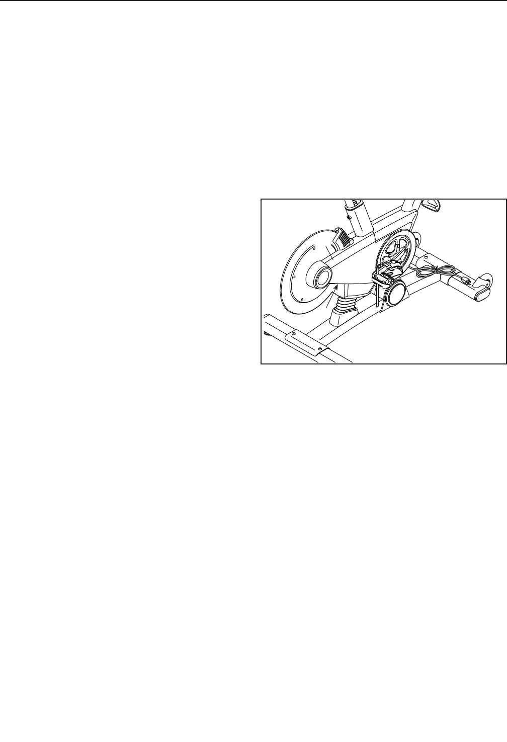
HOW TO ADJUST THE DRIVE BELT
If the pedals slip while you are pedaling, the drive belt
may need to be adjusted.
To adjust the drive belt, first press the power switch
to the off position and unplug the power cord.
Next, locate the access hole in the underside of the
Right Shield (12). Using a hex key, tighten the Idler
Adjustment Screw (39) until the drive belt (not shown)
is tight.
39
12
MAINTENANCE AND TROUBLESHOOTING
28
These guidelines will help you to plan your exercise
program. For detailed exercise information, obtain a
reputable book or consult your physician. Remember,
proper nutrition and adequate rest are essential for
successful results.
EXERCISE INTENSITY
Whether your goal is to burn fat or to strengthen your
cardiovascular system, exercising at the proper inten-
sity is the key to achieving results. You can use your
heart rate as a guide to find the proper intensity level.
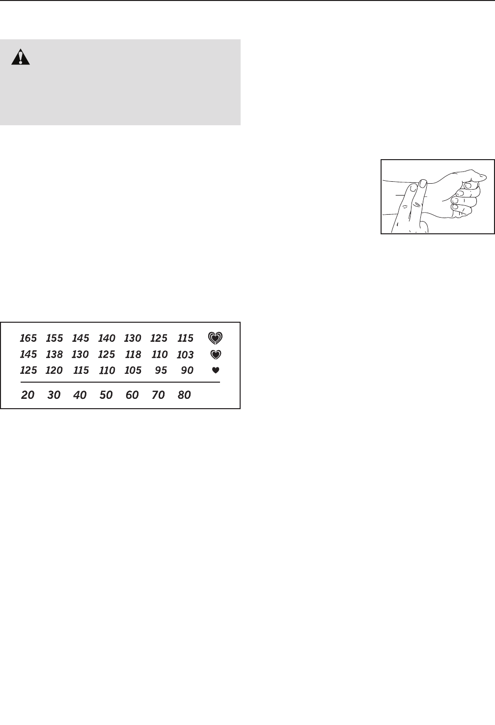
The chart below shows recommended heart rates for
fat burning and aerobic exercise.
To fi nd t he p ro pe r in te ns it y le vel, find y ou r ag e at t he
bottom of the chart (ages are rounded off to the near-
est ten years). The three numbers listed above your
age define your “training zone.” The lowest number is
the heart rate for fat burning, the middle number is the
heart rate for maximum fat burning, and the highest
number is the heart rate for aerobic exercise.
Burning Fat—To burn fat effectively, you must exer-
cise at a low intensity level for a sustained period of
time. During the first few minutes of exercise, your
body uses carbohydrate calories for energy. Only after
the first few minutes of exercise does your body begin
to use stored fat calories for energy. If your goal is to
burn fat, adjust the intensity of your exercise until your
heart rate is near the lowest number in your training
zone. For maximum fat burning, exercise with your
heart rate near the middle number in your training
zone.
Aerobic Exercise—If your goal is to strengthen your
cardiovascular system, you must perform aerobic
exercise, which is activity that requires large amounts
of oxygen for prolonged periods of time. For aerobic
exercise, adjust the intensity of your exercise until your
heart rate is near the highest number in your training
zone.
HOW TO MEASURE YOUR HEART RATE
To me as ur e yo ur h ea rt
rate, exercise for at least
four minutes. Then, stop
exercising and place
two fingers on your
wrist as shown. Take a
six-second heartbeat
count, and multiply the
result by 10 to find your heart rate. For example, if your
six-second heartbeat count is 14, your heart rate is 140
beats per minute.
WORKOUT GUIDELINES
Warming Up—Start with 5 to 10 minutes of stretch-
ing and light exercise. A warm-up increases your body
temperature, heart rate, and circulation in preparation
for exercise.
Training Zone Exercise—Exercise for 20 to 30 min-
utes with your heart rate in your training zone. (During
the first few weeks of your exercise program, do not
keep your heart rate in your training zone for longer
than 20 minutes.) Breathe regularly and deeply as you
exercise; never hold your breath.
Cooling Down—Finish with 5 to 10 minutes of stretch-
ing. Stretching increases the flexibility of your muscles
and helps to prevent post-exercise problems.
EXERCISE FREQUENCY
To ma in ta in o r im pr ov e yo ur c on dition, com pl et e th re e
workouts each week, with at least one day of rest
between workouts. After a few months of regular exer-
cise, you may complete up to five workouts each week,
if desired. Remember, the key to success is to make
exercise a regular and enjoyable part of your everyday
life.
WARNING: Before beginning this
or any exercise program, consult your physi-
cian. This is especially important for persons
over age 35 or persons with pre-existing
health problems.
EXERCISE GUIDELINES

29
K e y N o . Q t y . D e s c r i p t i o n K e y N o . Q t y . D e s c r i p t i o n
1 1 Base
2 1 Frame
3 1 Saddle Post
4 1 Saddle Carriage
5 1 Saddle
6 1 Handlebar Post
7 1 Handlebar
8 1 Tray
9 1 Console
10 1 Upper Shield
11 1 Left Shield
12 1 Right Shield
13 2 Shield Cover
14 1 Right Magnet Cover
15 1 Left Magnet Cover
16 1 Left Frame Cover
17 1 Right Frame Cover
18 1 Base Shield
19 1 Flex Cover
20 2 Cover Mount
21 2 Base Cover
22 1 Front Stabilizer
23 1 Rear Stabilizer
24 4 Stabilizer Cap
25 2 Leveling Foot
26 2 Foot
27 2 Wheel
28 1 Handlebar Clamp
29 2 Crank Cover
30 1 Lift Motor
31 1 Resistance Motor
32 1 Resistance Magnet
33 1 Arm
34 1 Magnet Axle
35 1 Right Saddle Post Sleeve
36 1 Left Saddle Post Sleeve
37 1 Idler Pulley
38 1 Idler Bolt
39 1 Idler Adjustment Screw
40 1 Flywheel Ring
41 1 Flywheel Hub
42 1 Flywheel Axle
43 1 Flywheel Spacer
44 1 Thrust Washer
45 1 Flywheel Pulley
46 1 Right Handlebar Post Sleeve
47 2 Adjustment Screw
48 1 Power Switch
49 1 Grommet
50 1 Control Board
51 1 Board Bracket
52 4 Standoff
53 1 Crank/Torque Pulley
54 3 M4 Washer
55 8 Magnet
56 1 Crank Screw
57 2 Bearing
58 1 Push Nut
59 2 Frame Bushing
60 1 Pivot Axle
61 1 Left Pedal
62 1 Right Pedal
63 1 Left Crank Arm
64 1 Right Crank Arm
65 2 Handlebar Cap
66 1 Drive Belt
67 1 Power Cord
68 1 Main Wire
69 1 Left Handlebar Post Sleeve
70 1 Left Shifter/Wire
71 3 3/8" Jam Nut
72 2 1/2" Washer
73 2 1/2" x 1" Screw
74 4 M10 x 58mm Screw
75 2 5/16" x 1 3/4" Bolt
76 2 5/16" Locknut
77 1 M10 x 35mm Hex Screw
78 2 Post Brake
79 5 M8 x 17mm Screw
80 1 Clamp
81 1 Right Shifter/Wire
82 5 #10 x 12mm Flat Head Screw
83 1 1/4" x 125mm Flat Head Screw
84 4 Wheel Spacer
85 2 M10 Washer
86 2 M8 x 15mm Screw
87 2 Lift Motor Bushing
88 1 Magnet Spring
89 5 M4 x 16mm Bright Screw
90 2 Friction Fastener
91 3 Carriage Cover
92 1 Saddle Mount Assembly
93 2 #8 Star Washer
94 2 M4 x 16mm Screw
95 10 #8 x 1/2" Self-tapping Screw
96 4 M4 x 12mm Flange Screw
97 7 M4 x 19mm Screw
98 1 Electronics Shield
99 2 1/4" Nut
100 1 M10 Locknut
PART LIST Model No. PFEX01414.0 R1114A

30
K e y N o . Q t y . D e s c r i p t i o n K e y N o . Q t y . D e s c r i p t i o n
101 1 Reed Switch/Wire
102 1 Crank Hub
103 10 Crank Spacer
104 4 M8 Locknut
105 1 Handlebar Carriage
106 5 M8 x 20mm Screw
107 1 Right Extension Wire
108 1 Left Extension Wire
109 10 M4 x 9mm Screw
110 4 M6 x 16mm Screw
111 4 M4 x 12mm Screw
112 1 Crank
113 2 #8 x 1/2" Screw
114 4 #8 x 1/2" Bright Screw
115 3 M8 x 15mm Round Head Screw
116 2 M4 x 10mm Screw
117 3 M4 x 14mm Screw
118 5 M8 x 30mm Screw
* – Lift Motor Wire
* – Resistance Motor Wire
* – Blue Wire
* – Green Wire
* – White Wire
* – Grease Packet
* – Assembly Tool
* – User’s Manual
Note: Specifications are subject to change without notice. For information about ordering replacement parts, see
the back cover of this manual. *These parts are not illustrated.
31
112
20
107
108
68
71
42
40
41
82
44
45
85
71
67
95
88
30
87
38
83
17 97
66
90 94
113
13 64
62
61
24
82
39
86 97
59
55
57
95
12
53
116
8
2
46
65
81
7
105
70
28
110
117
111
111
114
93
9
50
96
31 52
47
78
69
115
6
11
86
34 99
16
95
97
15
71
37
85
33
32
59
103 102 35
78
58
47
109
109
29
29
13
113
117
91 54 4
5
10
54
117
98
91
89
89
3
115
94 95 49 48 36
51
57
97
63
56
106
106
14
21
19
72
18
95
100
25
24 74
77
23 21
89
26
24
75 84
27
84
76 74 22
73
72
60
95
24
20
1
27
73
43
79
91
54
65
103
103
118
80
101
109
109
104
92 92
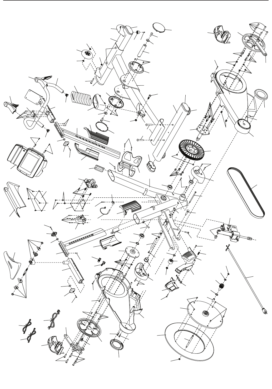
EXPLODED DRAWING Model No. PFEX01414.0 R1114A

Part No. 364523 R1114A Printed in China © 2014 ICON Health & Fitness, Inc.
To order replacement parts, please see the front cover of this manual. To help us assist you, be prepared to
provide the following information when contacting us:
• the model number and serial number of the product (see the front cover of this manual)
• the name of the product (see the front cover of this manual)
• the key number and description of the replacement part(s) (see the PART LIST and the EXPLODED DRAWING
near the end of this manual)
ORDERING REPLACEMENT PARTS
ICON Health & Fitness, Inc. (ICON) warrants this product to be free from defects in workmanship and
material, under normal use and service conditions. The frame is warranted for ten (10) years from the date
of purchase. Parts and labor are warranted for one (1) year from the date of purchase.
This warranty extends only to the original purchaser (customer). ICON’s obligation under this warranty is
limited to repairing or replacing, at ICON’s option, the product through one of its authorized service centers.
All repairs for which warranty claims are made must be preauthorized by ICON. If the product is shipped
to a service center, freight charges to and from the service center will be the customer’s responsibility. If
replacement parts are shipped while the product is under warranty, the customer will be responsible for a
minimal handling charge. For in-home service, the customer will be responsible for a minimal trip charge.
This warranty does not extend to freight damage to the product. This warranty will automatically be voided
if the product is used as a store display model, if the product is purchased or transported outside the USA,
if all instructions in this manual are not followed, if the product is abused or improperly or abnormally used,
or if the product is used for commercial or rental purposes. No other warranty beyond that specifi cally set
forth above is authorized by ICON.
ICON is not responsible or liable for indirect, special, or consequential damages arising out of or in con-
nection with the use or performance of the product; damages with respect to any economic loss, loss of
property, loss of revenues or profi ts, loss of enjoyment or use, or costs of removal or installation; or other
consequential damages of any kind. Some states do not allow the exclusion or limitation of incidental or
consequential damages. Accordingly, the above limitation may not apply to the customer.
The warranty extended hereunder is in lieu of any and all other warranties, and any implied warranties of
merchantability or fi tness for a particular purpose are limited in their scope and duration to the terms set
forth herein. Some states do not allow limitations on how long an implied warranty lasts. Accordingly, the
above limitation may not apply to the customer.
This warranty provides specifi c legal rights; the customer may have other rights that vary from state to state.
ICON Health & Fitness, Inc., 1500 S. 1000 W., Logan, UT 84321-9813
LIMITED WARRANTY
IMPORTANT: To protect your fitness equipment with an extended service plan, see page 5.
