Proxim Wireless 4954R Single Band Wireless AP W/ Build in Amplifiers User Manual 5054 4954 R
Proxim Wireless Corporation Single Band Wireless AP W/ Build in Amplifiers 5054 4954 R
Contents
- 1. User Manual 1 of 2
- 2. User Manual 2 of 2
- 3. User Manual Compliance Statement
- 4. User Manual
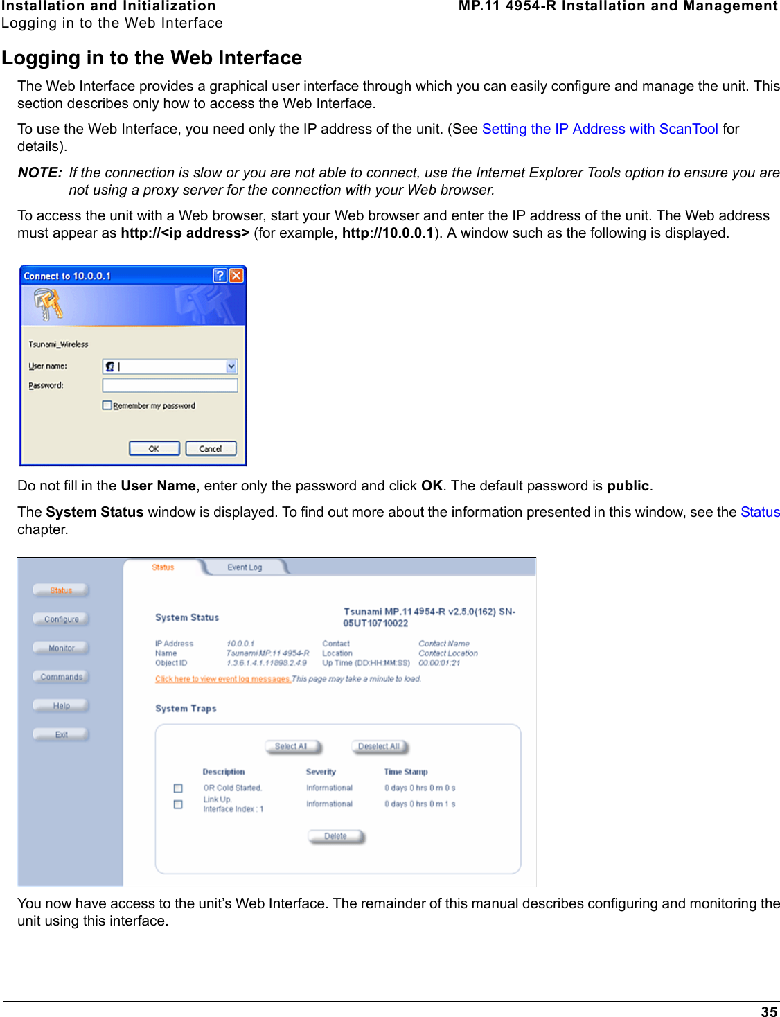
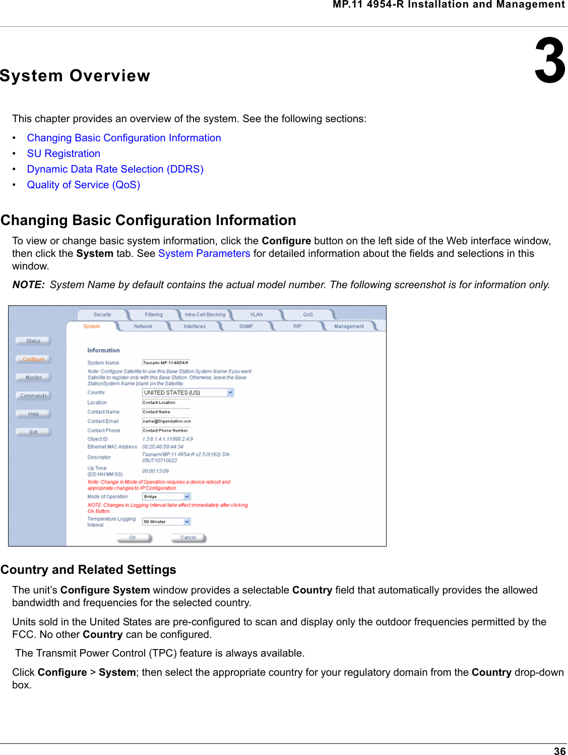
User Manual 1 of 2


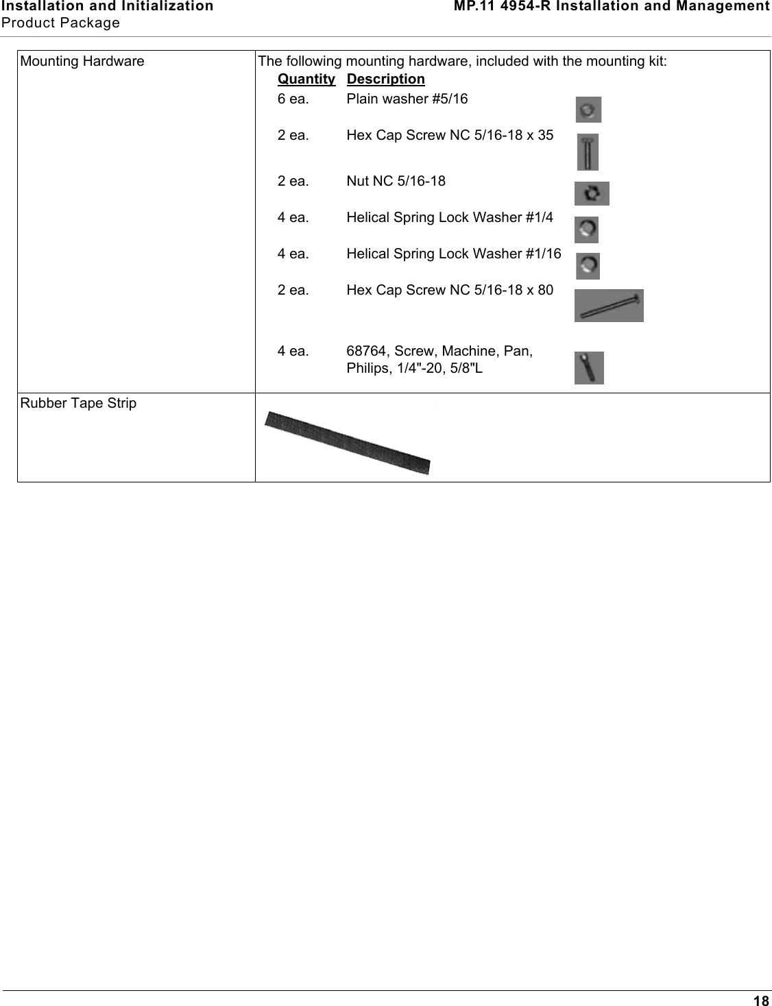
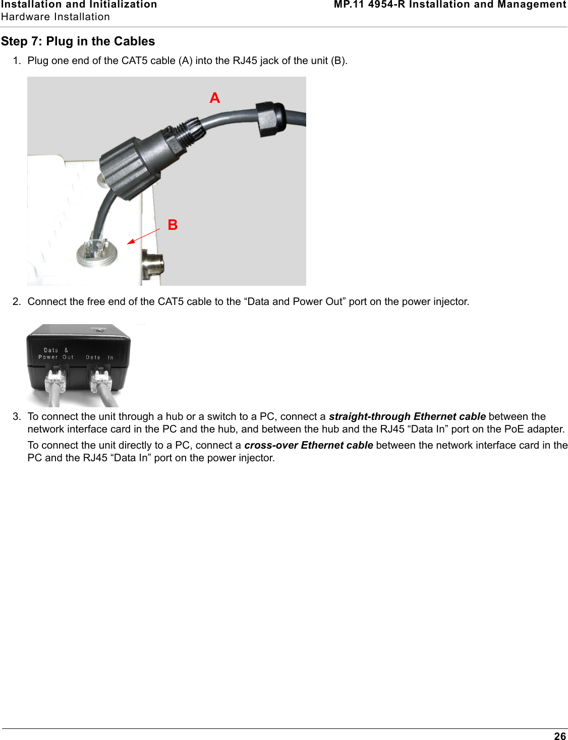
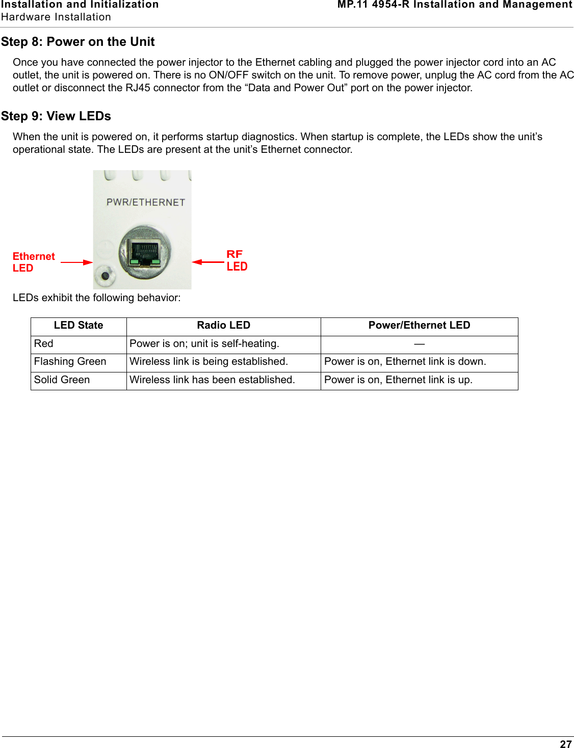
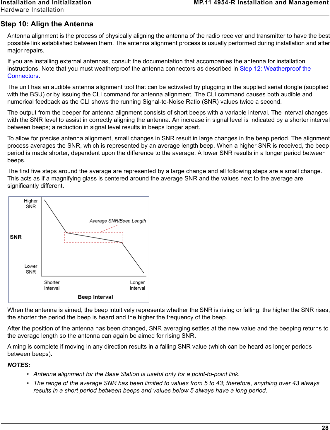

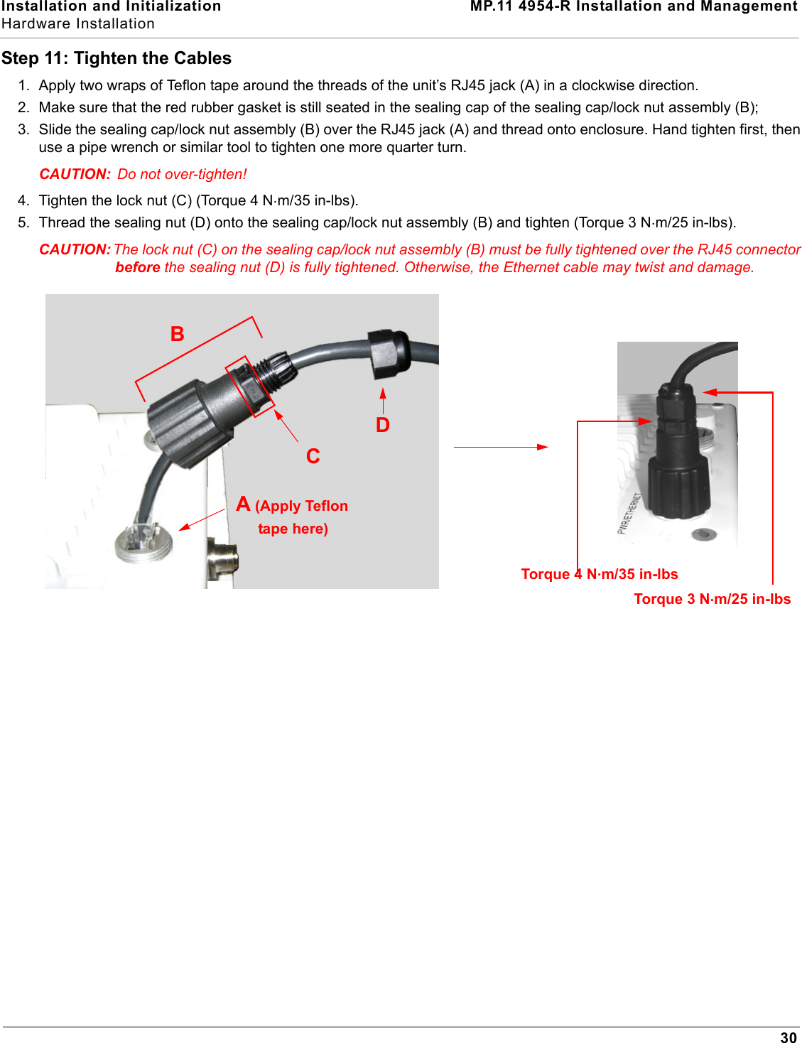
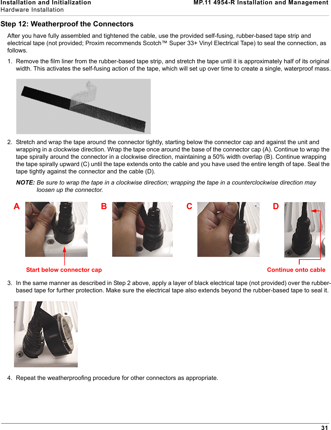

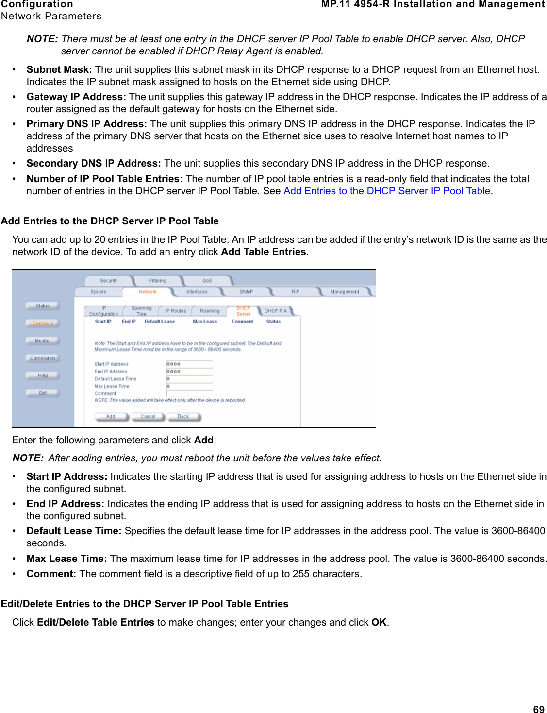
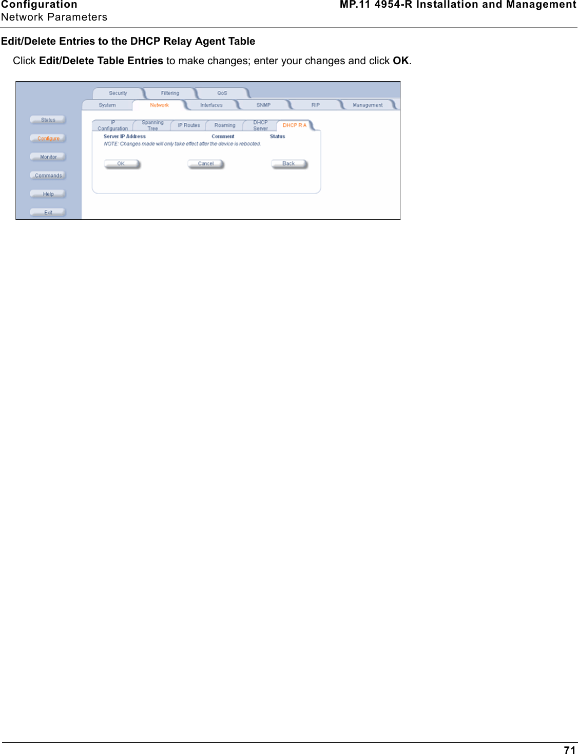
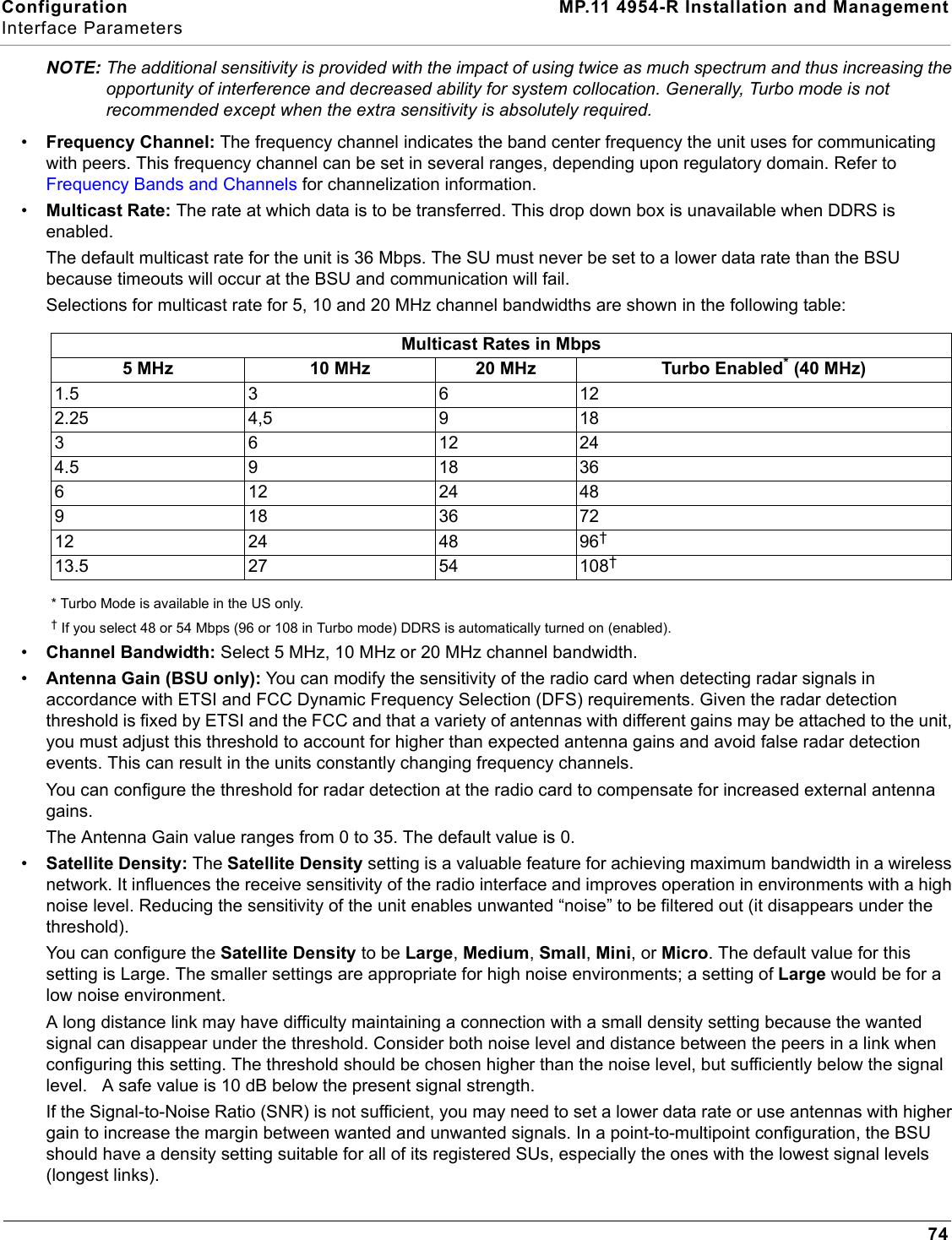
![System Overview MP.11 4954-R Installation and ManagementDynamic Data Rate Selection (DDRS)39Dynamic Data Rate Selection (DDRS)The WORP Dynamic Data Rate Selection (DDRS) lets the BSU and SUs monitor and calculate the remote average signal-to-noise ratio (SNR) and adjust the transmission data rate to an optimal value to provide the best possible throughput according to the current communication conditions and link quality during run-time.Each frame received in the WORP protocol reports the signal and noise level in dBm at which the sender received the previous frame from the receiver, and provides the values to calculate the SNR in dB. SNR is calculated according to this formula then averaged:SNR [dB] = signal level [dBm] – noise level [dBm]Both the BSU and the SUs monitor the remote SNR. The BSU monitors and calculates the average remote SNR for each SU that is registered. An SU monitors and calculates the average remote SNR for the BSU.DDRS is enabled or disabled on the BSU only. This operation requires the BSU to be rebooted. After rebooting, the BSU sends a multicast announcement to all SUs to begin the registration process. During registration, an SU is informed by the BSU whether DDRS is enabled or disabled and it sets its DDRS status accordingly.There are two DDRS data rates that need to be configured when DDRS is enabled:•Default DDRS Data Rate (ddrsdefdatarate): The data rate at which the BSU starts communication with all SUs to begin the registration process (the default is 6 Mbps).•Maximum DDRS Data Rate (ddrsmaxdatarate): The maximum data rate at which the device (BSU or SU) can operate (the default is 54 Mbps).NOTE: The default (BSU only) and maximum (BSU and SU) DDRS data rate values must be configured in the BSU and SUs separately through the CLI or the SNMP interface.](https://usermanual.wiki/Proxim-Wireless/4954R.User-Manual-1-of-2/User-Guide-741127-Page-41.png)