Proxim Wireless 4954R Single Band Wireless AP W/ Build in Amplifiers User Manual 5054 4954 R
Proxim Wireless Corporation Single Band Wireless AP W/ Build in Amplifiers 5054 4954 R
Contents
- 1. User Manual 1 of 2
- 2. User Manual 2 of 2
- 3. User Manual Compliance Statement
- 4. User Manual
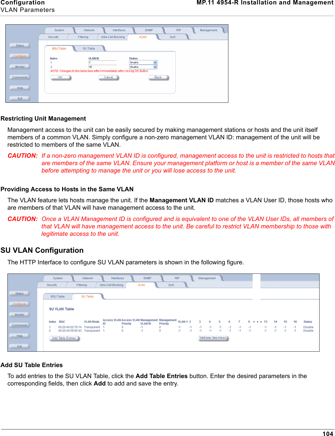
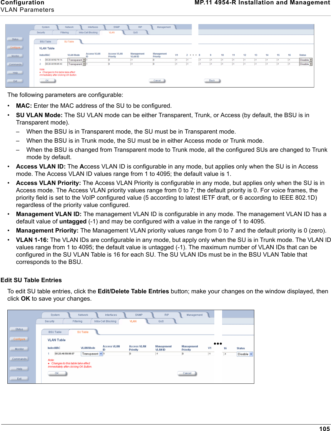
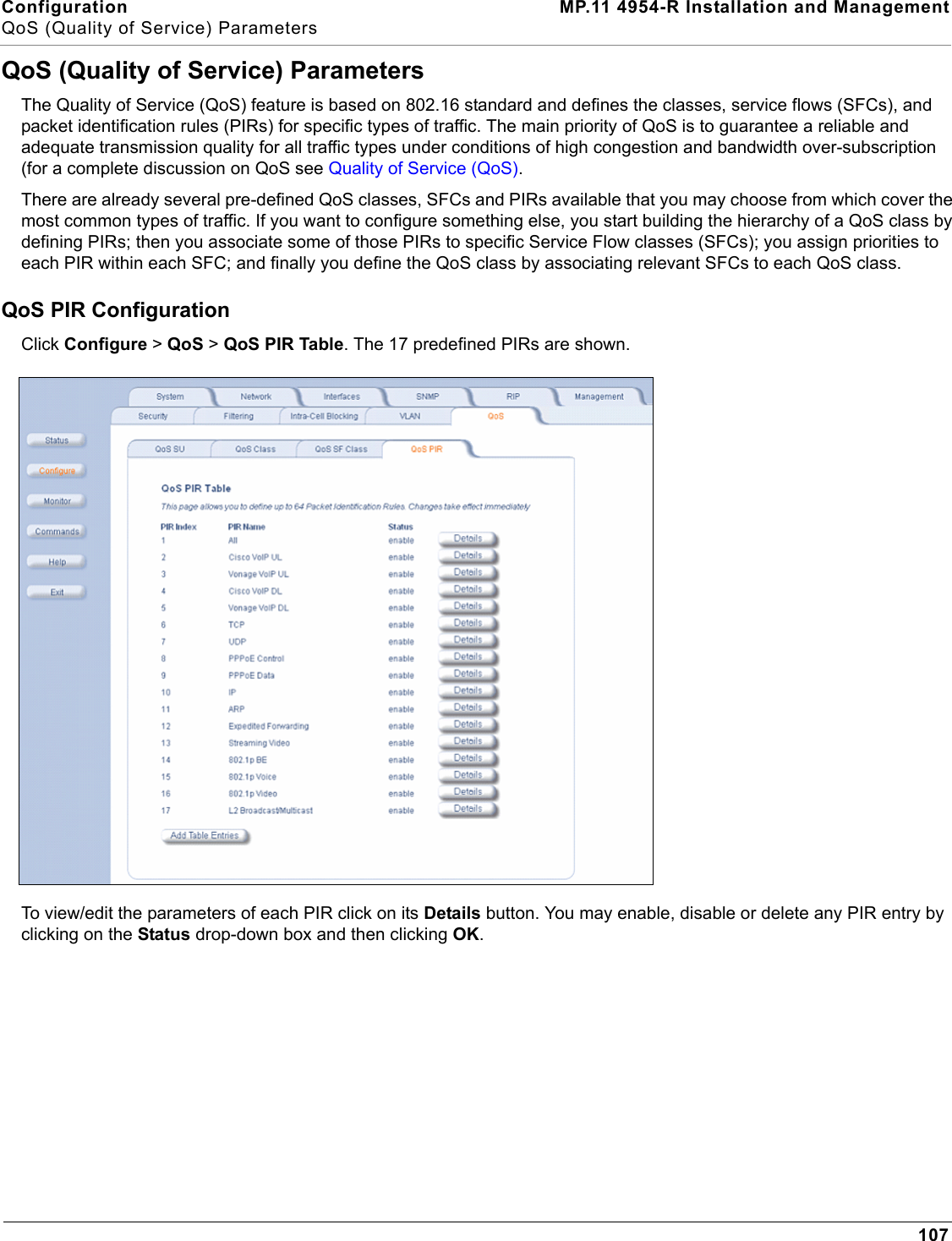
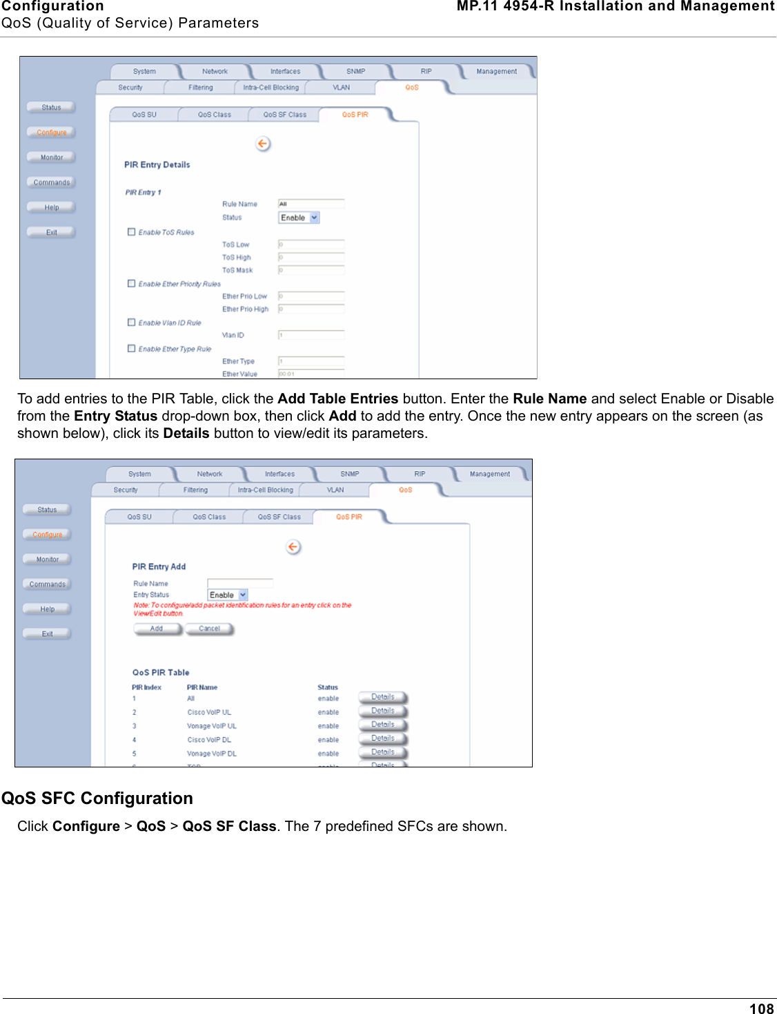
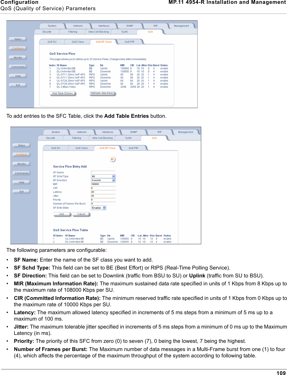
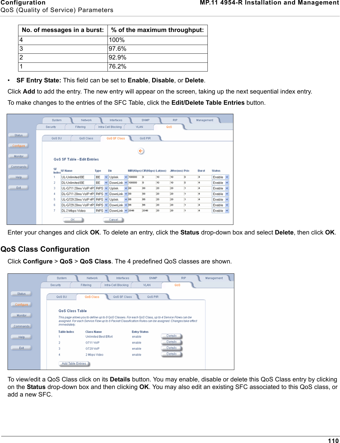
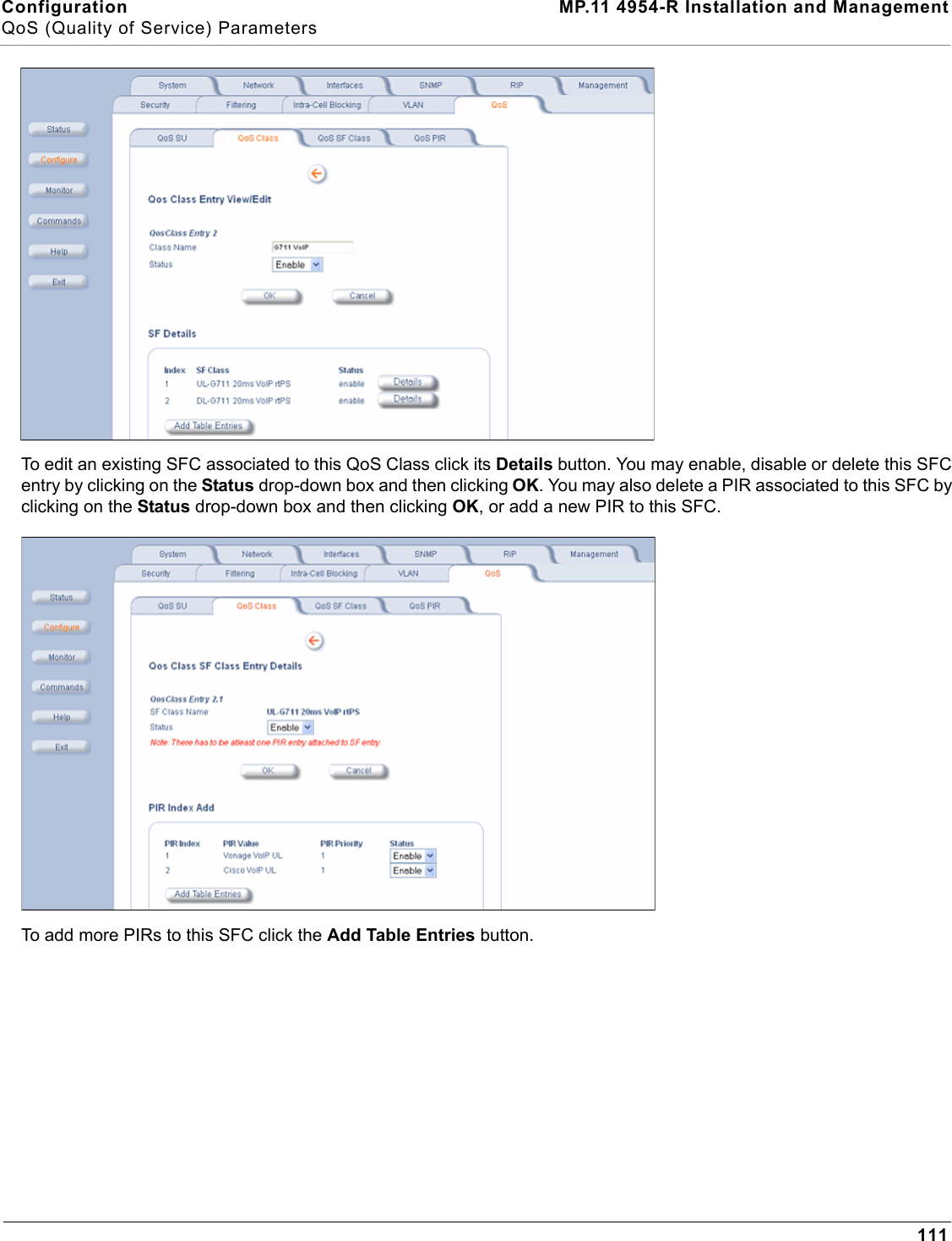
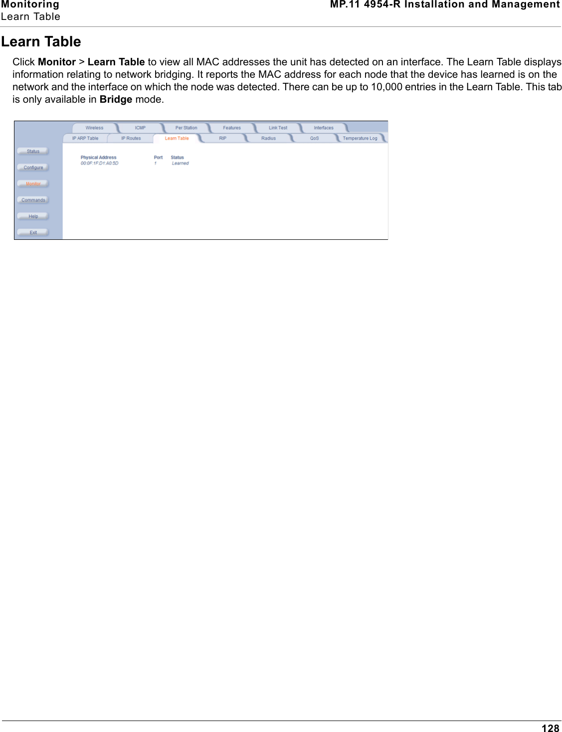
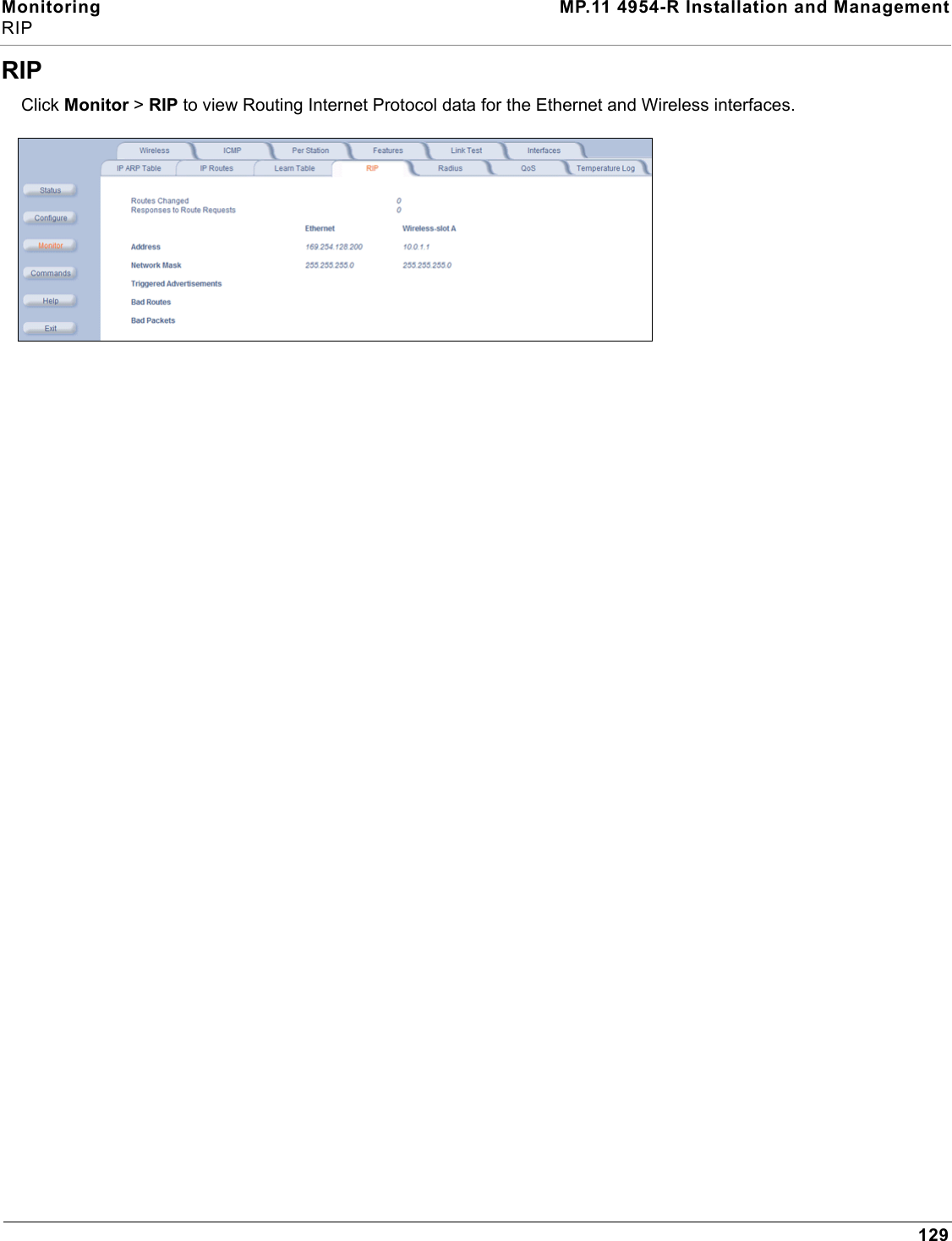
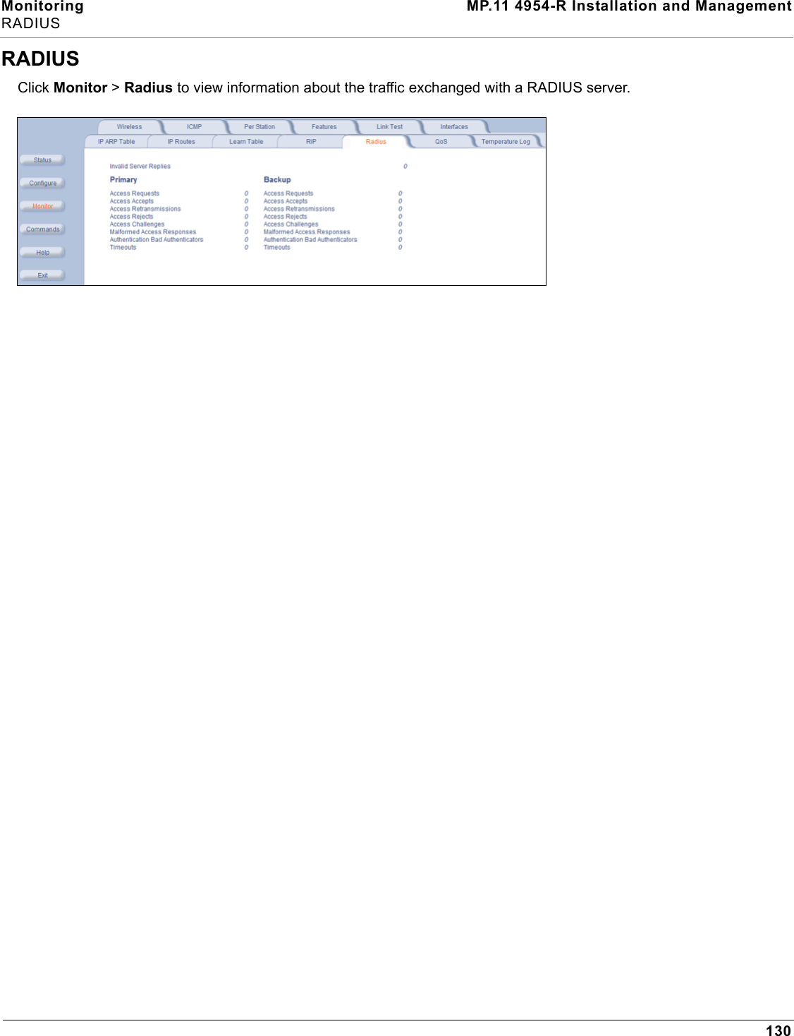
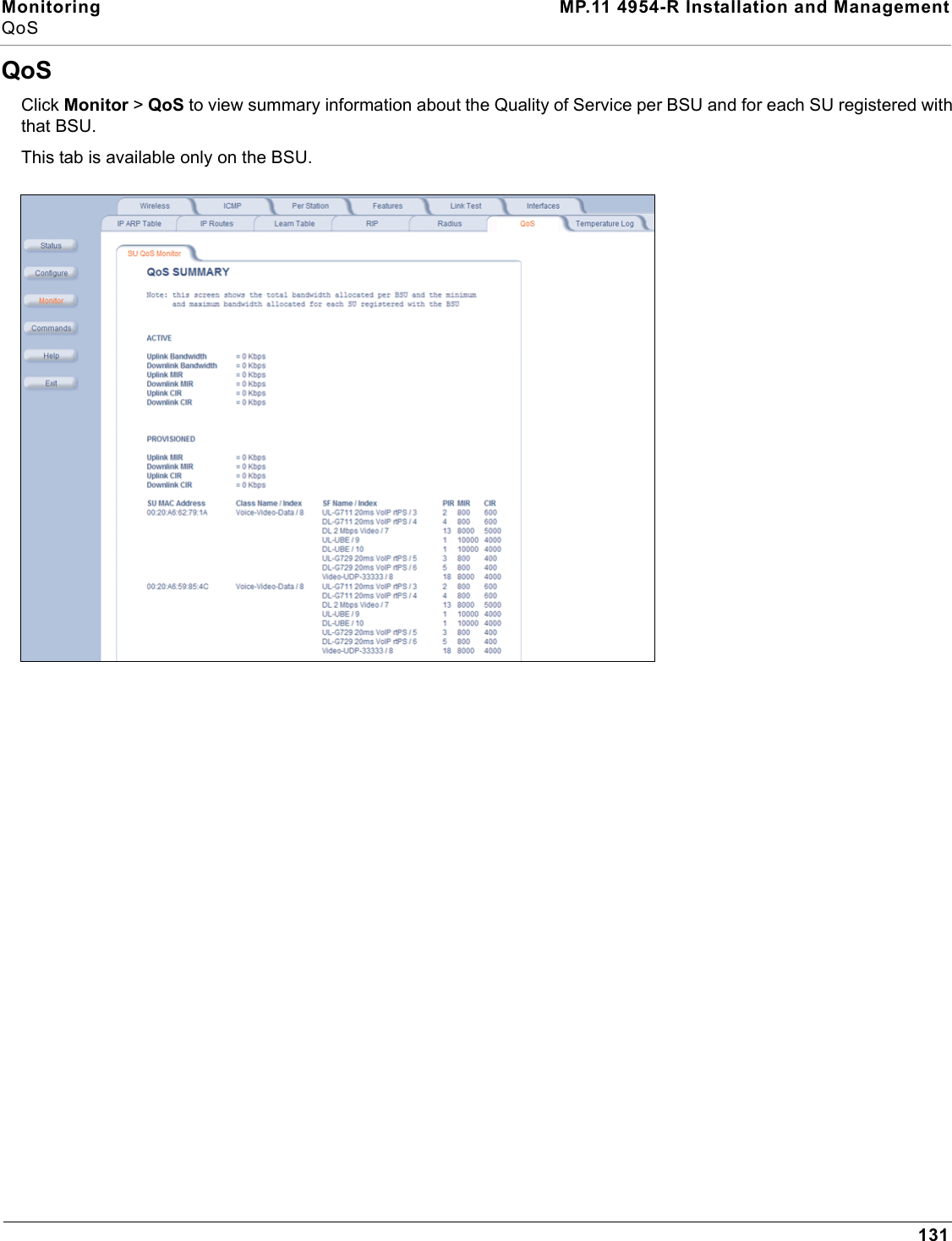
User Manual 2 of 2
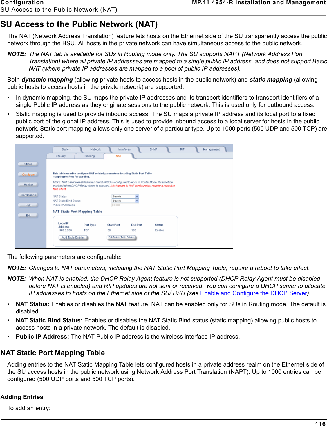
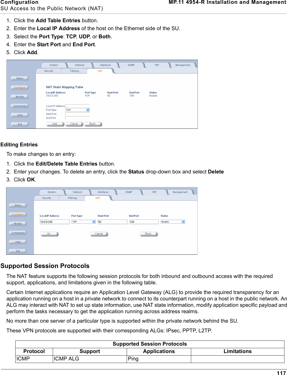
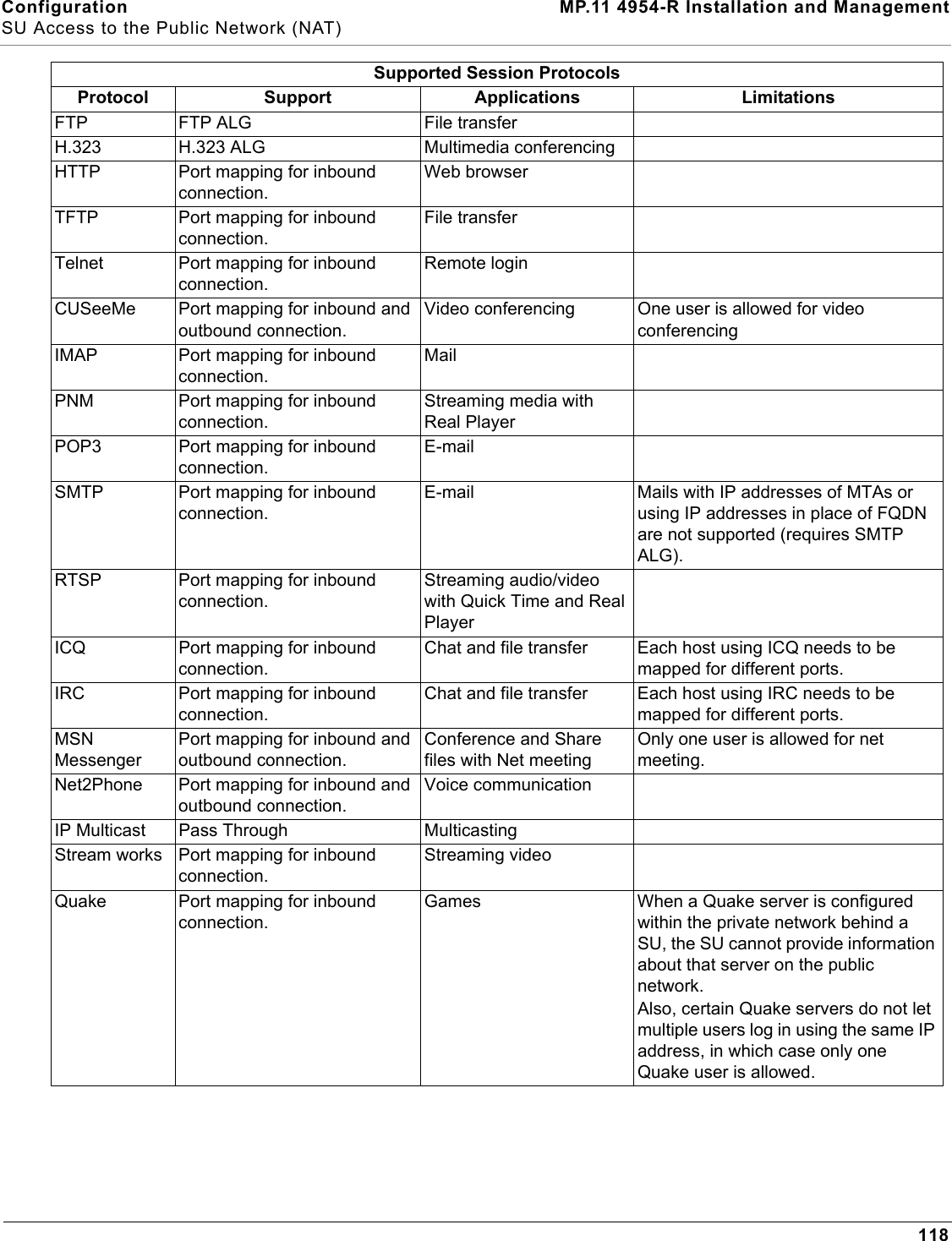
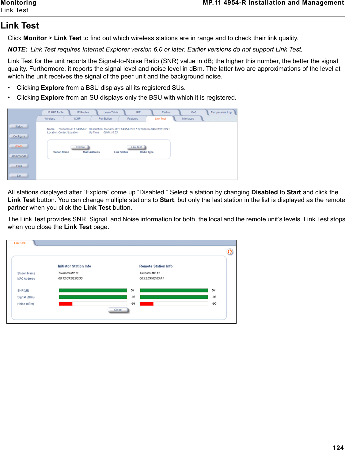
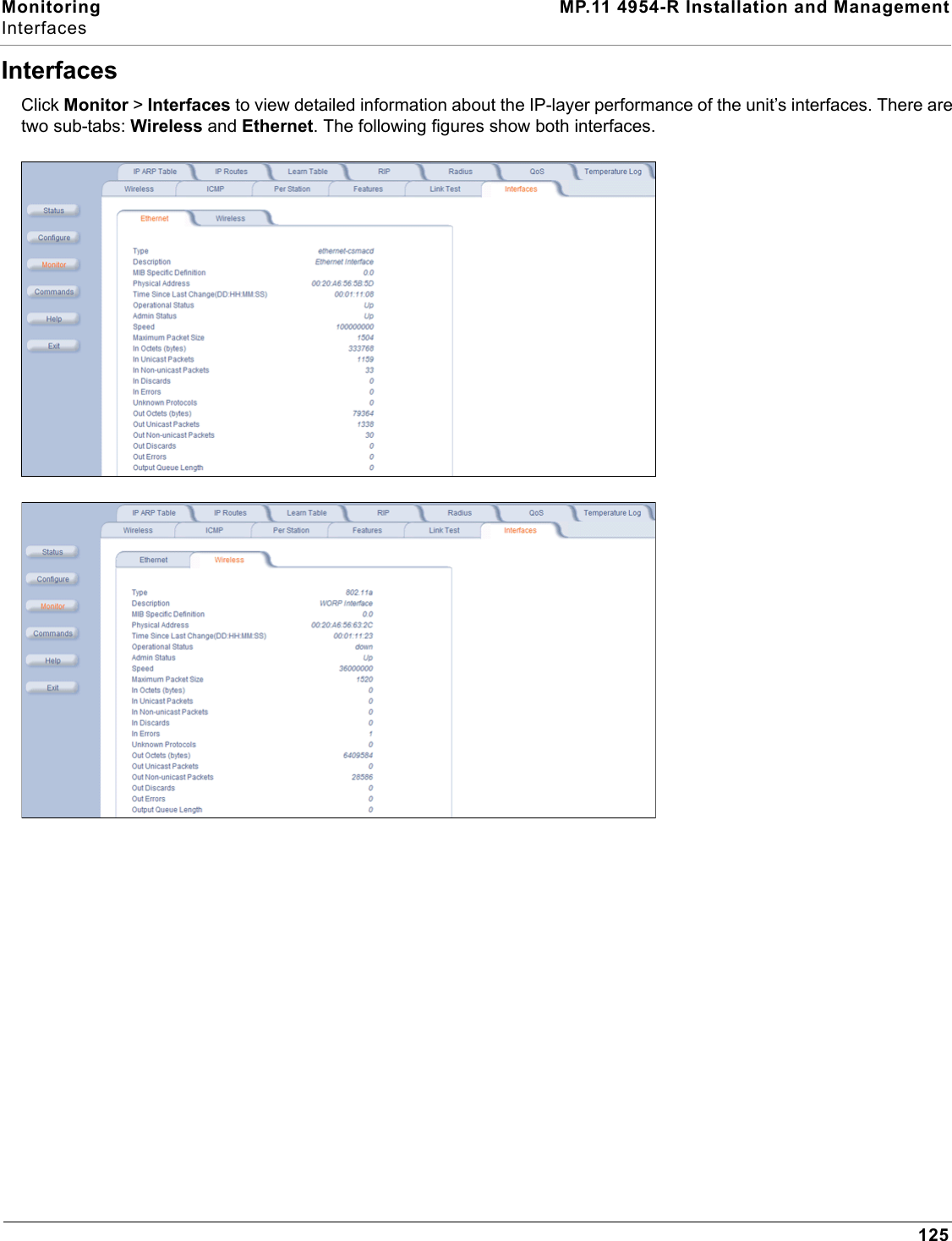
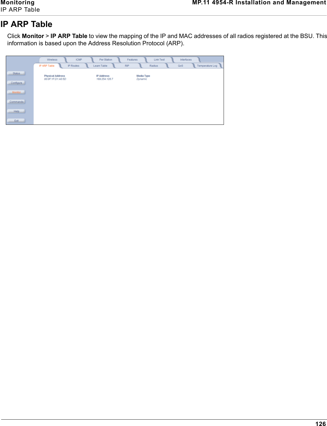
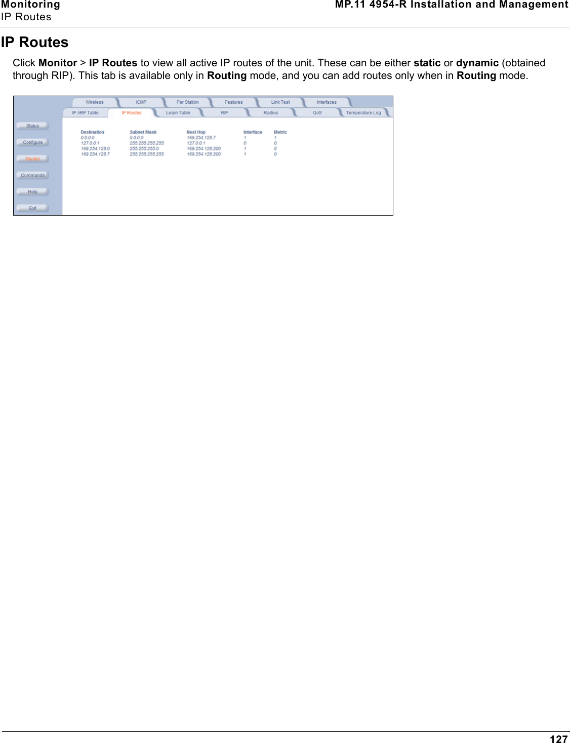
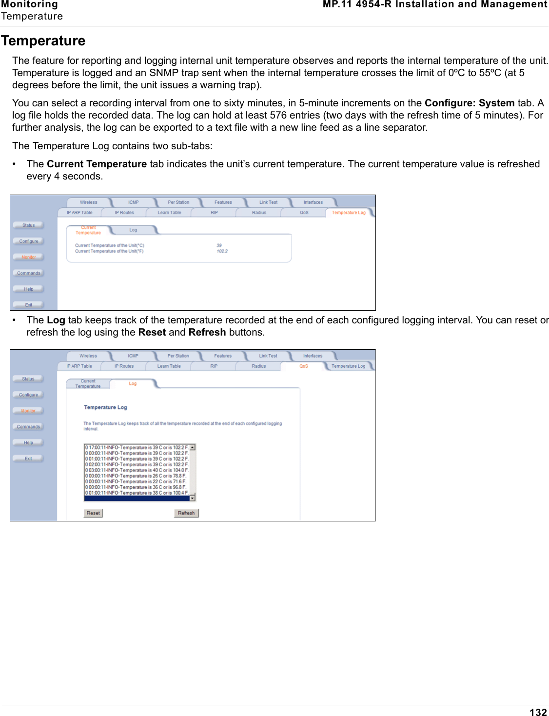
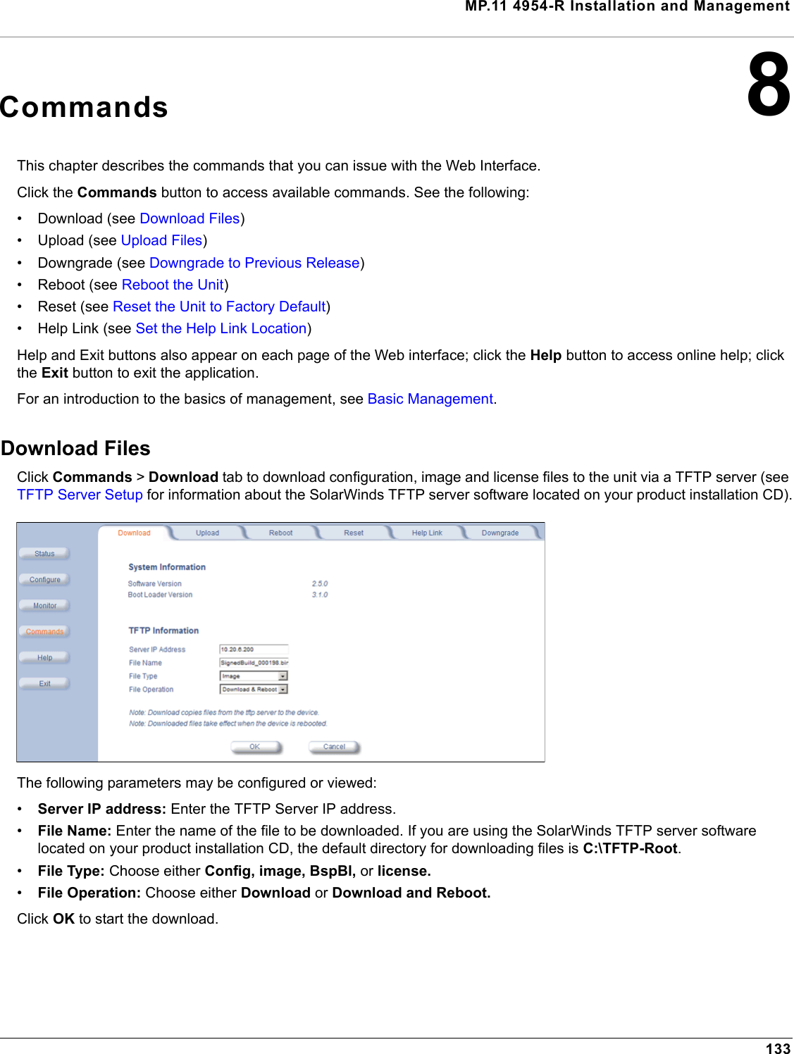
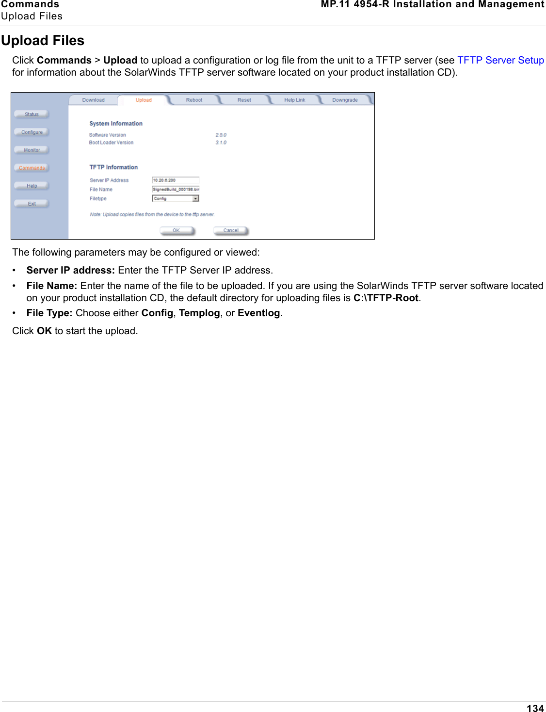
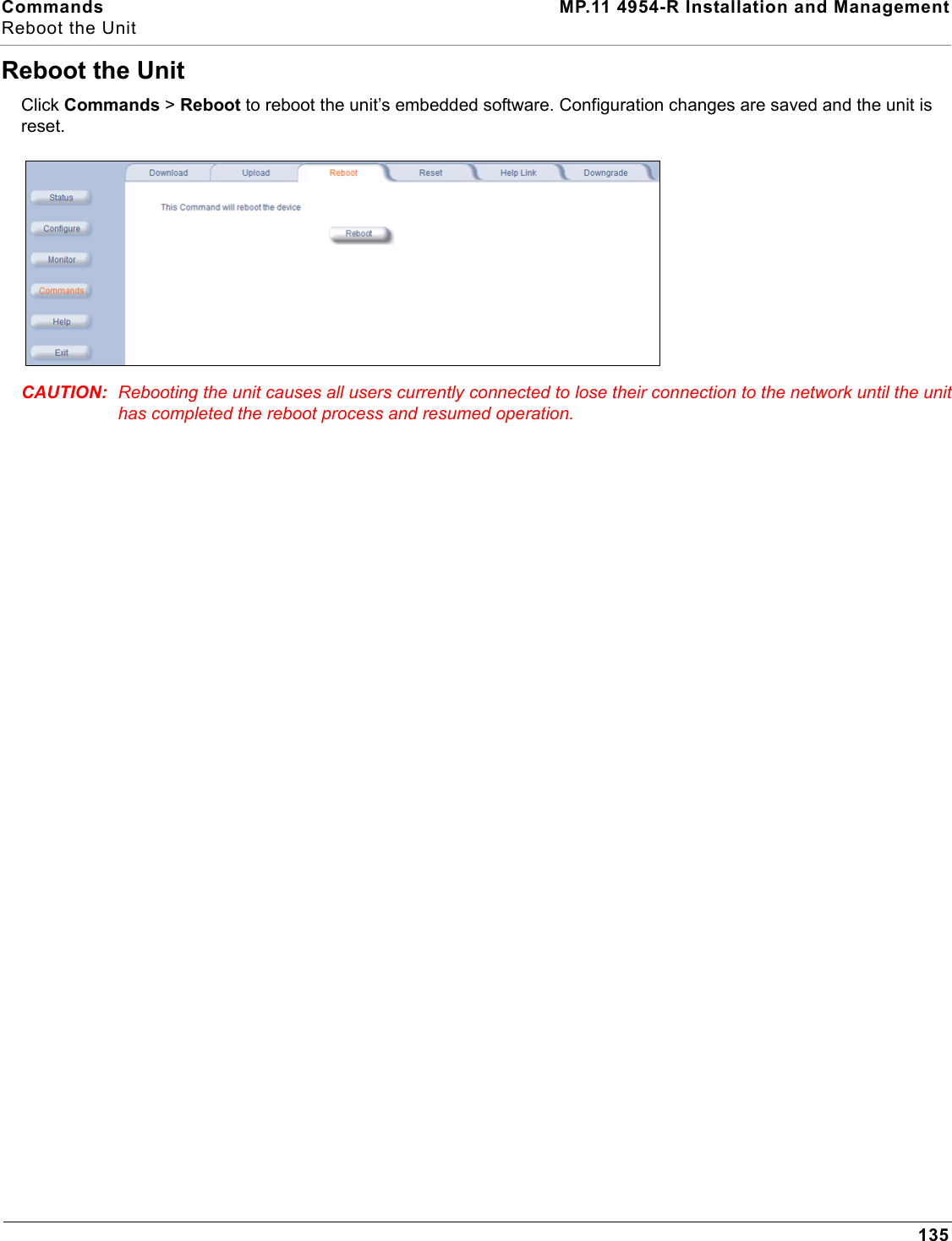
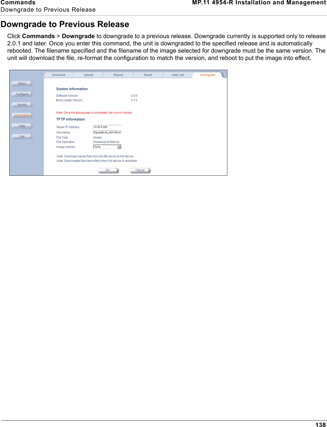
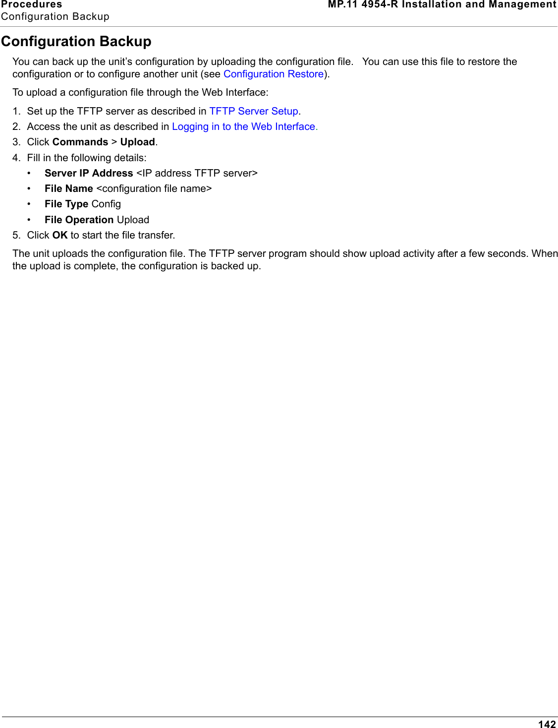
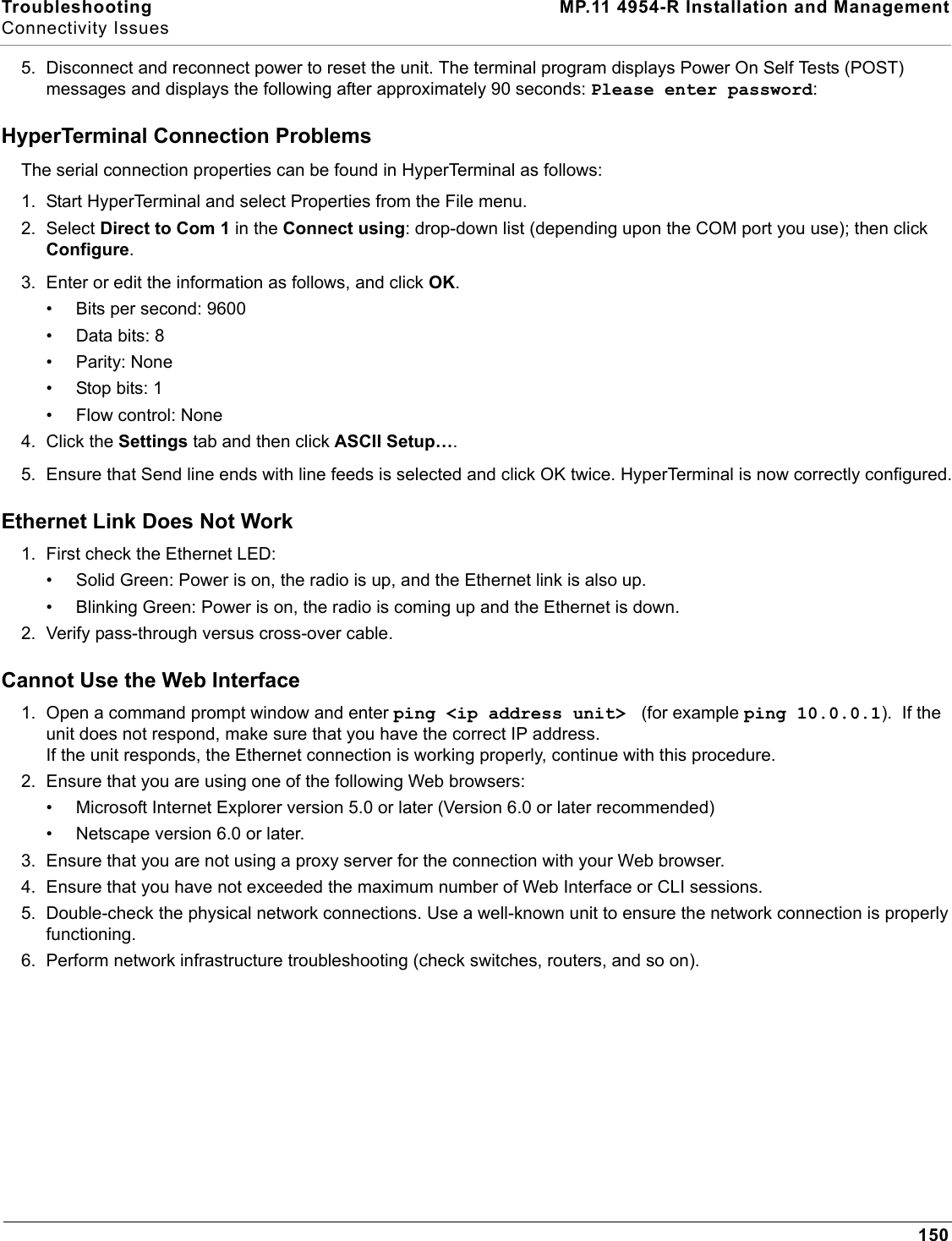
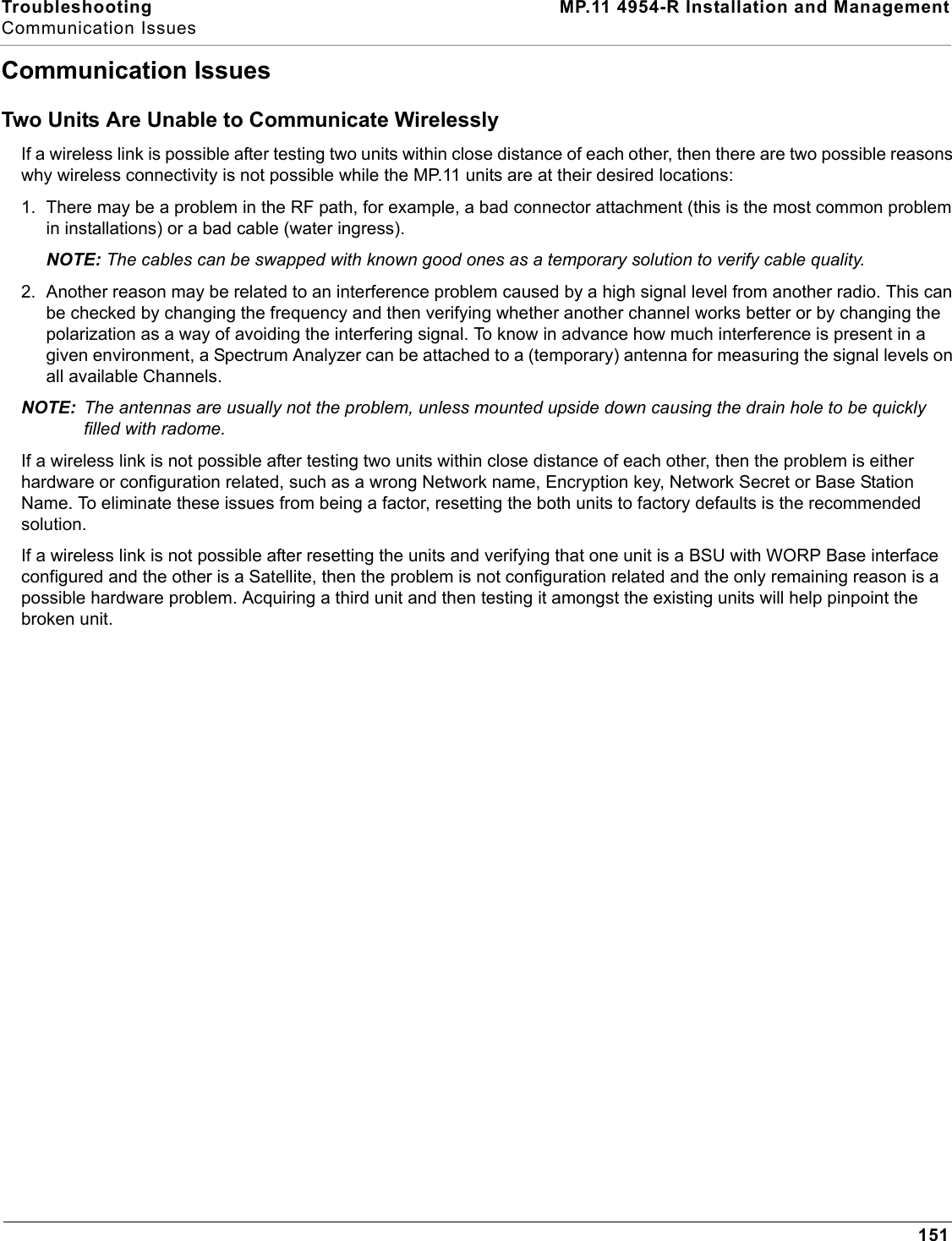
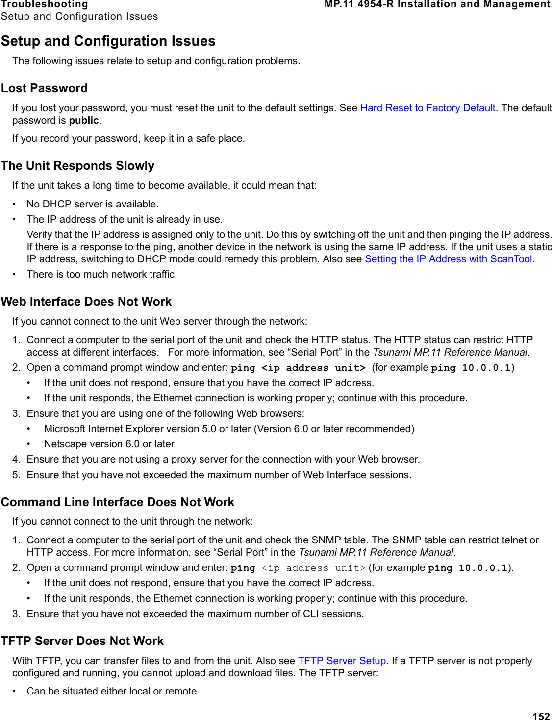
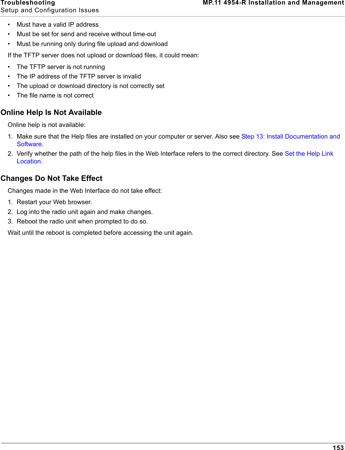
![Commands MP.11 4954-R Installation and ManagementSet the Help Link Location137Set the Help Link LocationClick Commands > Help Link to set the location of the help files of the Web Interface. Upon installation, the help files are installed in the C:\Program Files\Tsunami\MP.11 [Product Name]\Help folder.If you want to place these files on a shared drive, copy the Help folder to the new location and specify the new path in the Help Link box.](https://usermanual.wiki/Proxim-Wireless/4954R.User-Manual-2-of-2/User-Guide-741128-Page-39.png)