Proxim Wireless 4954R Single Band Wireless AP w/ Built in Amplifiers User Manual 5054 4954 R
Proxim Wireless Corporation Single Band Wireless AP w/ Built in Amplifiers 5054 4954 R
Contents
User Manual
Configuration MP.11 4954-R Installation and Management
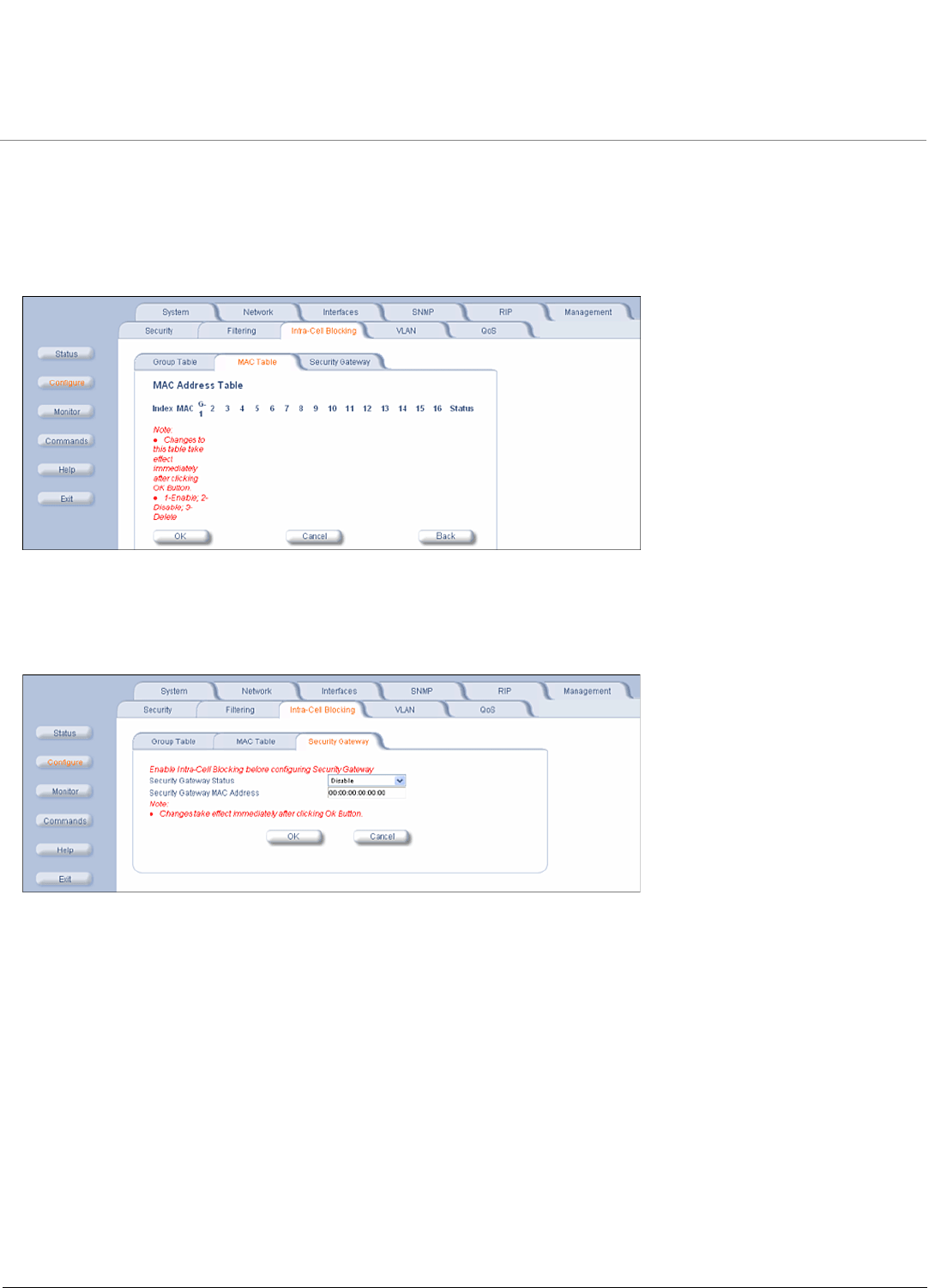
Intra-Cell Blocking (Base Station Unit Only)
99
Enter the MAC address of the SU. Select Enable from the drop-down menu for the Group Index
Click Add. The MAC address is assigned to the groups. Additions to the MAC Table take effect immediately after clicking
the Add button.
You can Enable, Disable, Delete, or Reassign the groups for a MAC address by using the Edit/Delete Table Entries
button. A maximum of 250 MAC addresses can be added among all filter groups.
Block Traffic Between SUs (Security Gateway)
You can configure a Security Gateway to block traffic between SUs connected to different BSUs. Verify that Intra-Cell
Blocking has been enabled on the Group Table tab before configuring the Security Gateway.
•Security Gateway Status: Enables or disables packet forwarding to the external Security Gateway.
•Security Gateway MAC Address: Lets you configure the MAC address of the external Security Gateway.

Configuration MP.11 4954-R Installation and Management
VLAN Parameters
100
VLAN Parameters
Virtual LAN (VLAN) implementation in the Tsunami products:
• Lets the BSU and SU be used in a VLAN-aware network.
• Processes IEEE 802.1Q VLAN-tagged packets.
Network resources behind the BSU and SU can be assigned to logical groups.
Overview
VLAN Modes
Transparent Mode
Transparent mode is available on both the SU and the BSU. This mode is equivalent to NO VLAN support and is the
default mode. It is used when the devices behind the SU and BSU are both VLAN aware and unaware. The SU/BSU
transfers both tagged and untagged frames received on the Ethernet or WORP interface. Both tagged and untagged
management frames can access the device.
Trunk Mode
Trunk mode VLAN is available on both the SU and the BSU. It is used when all devices behind the SU and BSU are
VLAN aware. The SU and BSU transfer only tagged frames received on the Ethernet or WORP interface. Both tagged
and untagged management frames can access the device.
Access Mode
Access mode is available only on the SU. It is used when the devices behind the SU are VLAN unaware. Frames to and
from the Ethernet interface behind the SU map into only one VLAN segment.
Frames received on the Ethernet interface are tagged with the configured Access VLAN ID before forwarding them to the
WORP interface. Both tagged and untagged management frames can access the device from the WORP interface.
However, only untagged management frames can access the device from the Ethernet Interface.
VLAN Forwarding
The VLAN Trunk mode provides a means to configure a list of VLAN IDs in a Trunk VLAN Table. The SU and BSU only
forward frames (between Ethernet and WORP interface) tagged with the VLAN IDs configured in the Trunk VLAN Table.
Up to 256 VLAN IDs can be configured for the BSU and up to 16 VLAN IDs can be configured for the SU (depending
upon the capabilities of your switching equipment).
VLAN Relaying
The VLAN Trunk mode for BSU operation provides an option to enable and disable a VLAN relaying flag; when enabled,
the BSU shall relay frames between SUs on the same BSU having the same VLAN ID.
Management VLAN
The BSU and SU allow the configuration of a separate VLAN ID and priority for SNMP, ICMP, Telnet, and TFTP
management frames for device access.
The management VLAN ID and management VLAN priority may be applied in any mode. The management stations tag
the management frames they send to the BSU or SU with the management VLAN ID configured in the device. The BSU
and SU tag all the management frames from the device with the configured management VLAN and priority.
Configuration MP.11 4954-R Installation and Management
VLAN Parameters
101
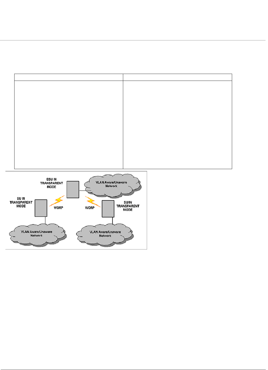
BSU and SU in Transparent Mode
When the BSU is in Transparent mode, all associated SUs must be in Transparent mode.
How the BSU and SUs function in Transparent mode is described in the following table.
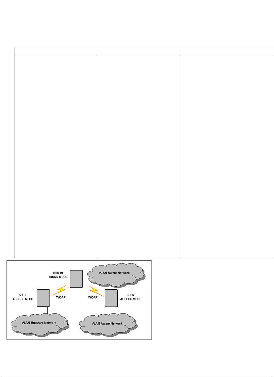
BSU in Trunk Mode and SU in Trunk/Access Mode
When the BSU is in Trunk mode, the associated SUs must be in either Trunk mode or Access mode. When an SU
associates to a BSU that is in Trunk mode, it gets the VLAN mode from the BSU.
How the BSU and SU function in Trunk mode, and the SU in Access mode, is described in the following table.
BSU Function – Transparent Mode SU Function – Transparent Mode
• BSU forwards both tagged and untagged
frames received from the Ethernet interface or
from any of the associated SUs.
• If a valid management VLAN ID is configured,
BSU allows only management frames tagged
with the configured management VLAN ID to
access it.
• If a valid management VLAN ID is configured,
BSU tags all management frames generated
by the BSU with the configured management
VLAN ID and priority.
• If the management VLAN ID is configured as -
1 (untagged), BSU allows only untagged
management frames to access it.
• SU forwards both tagged and untagged
frames received from the Ethernet interface or
from the BSU.
• If a valid management VLAN ID is configured,
SU allows only management frames tagged
with the configured management VLAN ID to
access it.
• If a valid management VLAN ID is configured,
SU tags all management frames generated by
the SU with the configured management VLAN
ID and priority.
• If the management VLAN ID is configured as -
1 (untagged), SU allows only untagged
management frames to access them.
Configuration MP.11 4954-R Installation and Management
VLAN Parameters
102
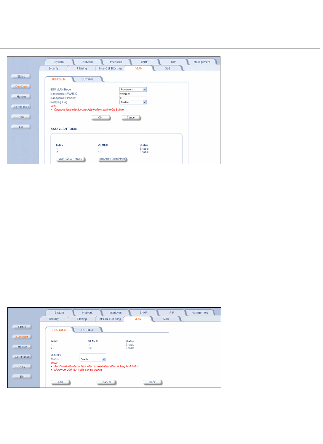
BSU VLAN Configuration
The HTTP Interface to configure BSU VLAN parameters is shown in the following figure.
BSU Function – Trunk Mode SU Function – Trunk Mode SU Function – Access Mode
• Up to 256 VLAN IDs can be
configured on a BSU.
• BSU discards all untagged
frames received from the
Ethernet interface or from any of
the associated SUs
(unexpected).
• If a valid VLAN ID is configured,
BSU forwards only VLAN-tagged
frames received from the
Ethernet interface or from any of
the associated SUs that are
tagged with the configured VLAN
IDs; it discards all other tagged
frames.
• If a valid management VLAN ID is
configured, BSU allows only
management frames tagged with
the configured management
VLAN ID to access it.
• If a valid management VLAN ID is
configured, BSU tags all
management frames generated
by the BSU with the configured
management VLAN ID and
priority.
• If the management VLAN ID is
configured as -1 (untagged), BSU
allows only untagged
management frames to access it.
• Up to 16 VLAN IDs can be
configured on an SU.
• SU discards all untagged frames
received from the Ethernet
interface or from the BSU
(unexpected).
• If a valid VLAN ID is configured,
SU forwards only VLAN-tagged
frames received from the
Ethernet interface or from the
BSU that are tagged with the
configured VLAN IDs; it discards
all other tagged frames.
• If a valid management VLAN ID is
configured, SU allows only
management frames tagged with
the configured management
VLAN ID to access it.
• If a valid management VLAN ID is
configured, SU tags all
management frames generated
by the SU with the configured
management VLAN ID and
priority.
• If the management VLAN ID is
configured as -1 (untagged), SU
allows only untagged
management frames to access it.
• SU discards all tagged frames received
from the Ethernet interface and all
untagged frames received from the
BSU (unexpected).
• SU tags all untagged frames received
from the Ethernet interface with the
configured Access VLAN ID and
forwards them to the BSU.
• SU untags all tagged frames received
from the BSU that are tagged with the
configured Access VLAN ID and
forwards them to the Ethernet
interface; it discards all other tagged
frames from the BSU.
• If a valid management VLAN ID is
configured, SU allows only
management frames tagged with the
configured management VLAN ID to
access it from the BSU.
• If a valid management VLAN ID is
configured, SU tags all management
frames generated by the SU with the
configured management VLAN ID and
priority and forwards them to the BSU.
• If the management VLAN ID is
configured as -1 (untagged), SU allows
only untagged management frames to
access it from the BSU.
• SU allows only untagged management
frames to access it from the Ethernet
interface, regardless of the value of the
management VLAN ID.
Configuration MP.11 4954-R Installation and Management
VLAN Parameters
103
The following parameters are configurable:
•BSU VLAN Mode: The BSU VLAN mode can be either Transparent or Trunk. By default, the BSU is in Transparent
mode.
•Management VLAN ID: The Management VLAN ID is configurable in any mode. The management VLAN ID has a
default value of untagged and may be configured with a value in the range of 1 to 4095.
•Management VLAN Priority: The Management VLAN priority values range from 0 to 7 and the default priority is 0
(zero).
•Relaying Flag: When this flag is enabled, the BSU relays frames between SUs on the same BSU.
•BSU VLAN Table: The BSU VLAN Table is configurable in both Transparent and Trunk mode, but applies only when
the BSU is in Trunk mode. The VLAN ID values for the BSU VLAN Table range from 1 to 4095. The maximum number
of VLAN IDs that can be configured in the BSU VLAN Table is 256. An SU in Trunk mode is assigned VLAN IDs from
this table.
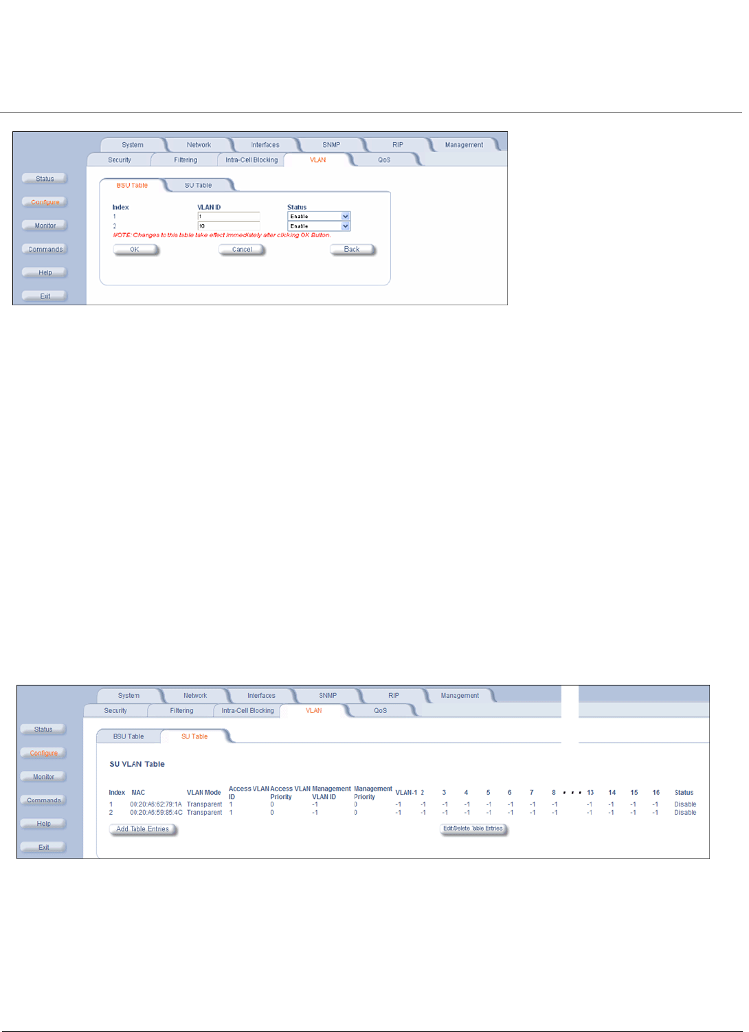
Add BSU VLAN Table Entries
To add entries to the BSU VLAN table, click the Add Table Entries button. Enter a VLAN ID and select a Status, then
click Add to add your entry to the table.
Edit or Delete BSU VLAN Table Entries
To edit or delete entries in the BSU VLAN Table, click the Edit/Delete Table Entries button, make your changes, then
click OK for your changes to take effect.
Configuration MP.11 4954-R Installation and Management
VLAN Parameters
104
Restricting Unit Management
Management access to the unit can be easily secured by making management stations or hosts and the unit itself
members of a common VLAN. Simply configure a non-zero management VLAN ID: management of the unit will be
restricted to members of the same VLAN.
CAUTION: If a non-zero management VLAN ID is configured, management access to the unit is restricted to hosts that
are members of the same VLAN. Ensure your management platform or host is a member of the same VLAN
before attempting to manage the unit or you will lose access to the unit.
Providing Access to Hosts in the Same VLAN
The VLAN feature lets hosts manage the unit. If the Management VLAN ID matches a VLAN User ID, those hosts who
are members of that VLAN will have management access to the unit.
CAUTION: Once a VLAN Management ID is configured and is equivalent to one of the VLAN User IDs, all members of
that VLAN will have management access to the unit. Be careful to restrict VLAN membership to those with
legitimate access to the unit.
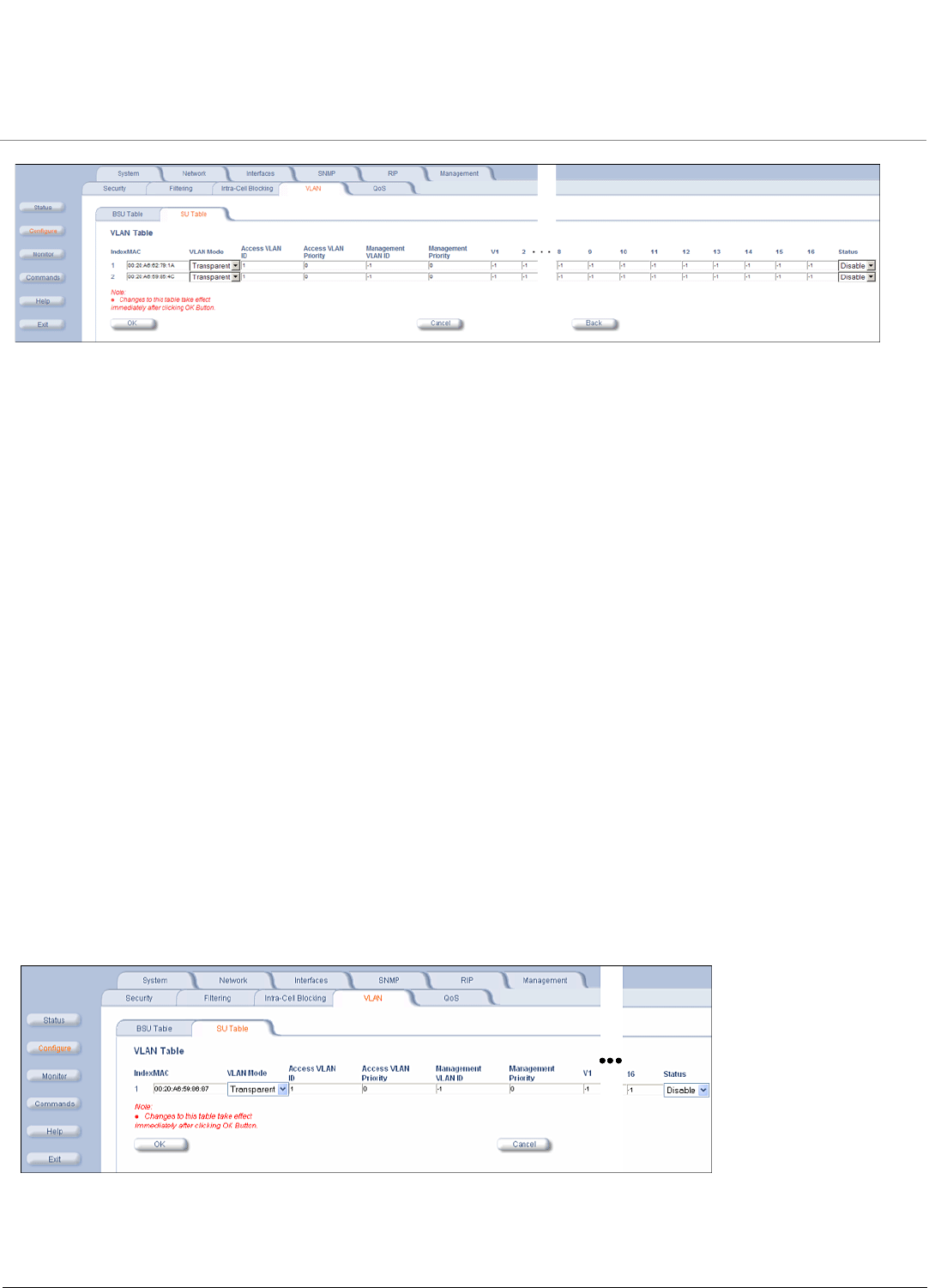
SU VLAN Configuration
The HTTP Interface to configure SU VLAN parameters is shown in the following figure.
Add SU Table Entries
To add entries to the SU VLAN Table, click the Add Table Entries button. Enter the desired parameters in the
corresponding fields, then click Add to add and save the entry.
Configuration MP.11 4954-R Installation and Management
VLAN Parameters
105
The following parameters are configurable:
•MAC: Enter the MAC address of the SU to be configured.
•SU VLAN Mode: The SU VLAN mode can be either Transparent, Trunk, or Access (by default, the BSU is in
Transparent mode).
– When the BSU is in Transparent mode, the SU must be in Transparent mode.
– When the BSU is in Trunk mode, the SU must be in either Access mode or Trunk mode.
– When the BSU is changed from Transparent mode to Trunk mode, all the configured SUs are changed to Trunk
mode by default.
•Access VLAN ID: The Access VLAN ID is configurable in any mode, but applies only when the SU is in Access
mode. The Access VLAN ID values range from 1 to 4095; the default value is 1.
•Access VLAN Priority: The Access VLAN Priority is configurable in any mode, but applies only when the SU is in
Access mode. The Access VLAN priority values range from 0 to 7; the default priority is 0. For voice frames, the
priority field is set to the VoIP configured value (5 according to latest IETF draft, or 6 according to IEEE 802.1D)
regardless of the priority value configured.
•Management VLAN ID: The management VLAN ID is configurable in any mode. The management VLAN ID has a
default value of untagged (-1) and may be configured with a value in the range of 1 to 4095.
•Management Priority: The Management VLAN priority values range from 0 to 7 and the default priority is 0 (zero).
•VLAN 1-16: The VLAN IDs are configurable in any mode, but apply only when the SU is in Trunk mode. The VLAN ID
values range from 1 to 4095; the default value is untagged (-1). The maximum number of VLAN IDs that can be
configured in the SU VLAN Table is 16 for each SU. The SU VLAN IDs must be in the BSU VLAN Table that
corresponds to the BSU.
Edit SU Table Entries
To edit SU table entries, click the Edit/Delete Table Entries button; make your changes on the window displayed, then
click OK to save your changes.

Configuration MP.11 4954-R Installation and Management
VLAN Parameters
106
Typical User VLAN Configurations
VLANs segment network traffic into groups, which lets you limit broadcast and multicast traffic. These groups enable
hosts from different VLANs to access different resources using the same network infrastructure. Hosts using the same
physical network are limited to those resources available to their workgroup.
The unit can segment users into a maximum of 16 different VLANs per unit, based upon a VLAN ID.
The primary scenarios for using VLAN workgroups are as follows:
•VLAN disabled: Your network does not use VLANs.
•VLAN enabled: Each VLAN workgroup uses a different VLAN ID Tag. A mixture of Tagged and Untagged workgroups
may be supported.
Configuration MP.11 4954-R Installation and Management
QoS (Quality of Service) Parameters
107
QoS (Quality of Service) Parameters
The Quality of Service (QoS) feature is based on 802.16 standard and defines the classes, service flows (SFCs), and
packet identification rules (PIRs) for specific types of traffic. The main priority of QoS is to guarantee a reliable and
adequate transmission quality for all traffic types under conditions of high congestion and bandwidth over-subscription
(for a complete discussion on QoS see Quality of Service (QoS).
There are already several pre-defined QoS classes, SFCs and PIRs available that you may choose from which cover the
most common types of traffic. If you want to configure something else, you start building the hierarchy of a QoS class by
defining PIRs; then you associate some of those PIRs to specific Service Flow classes (SFCs); you assign priorities to
each PIR within each SFC; and finally you define the QoS class by associating relevant SFCs to each QoS class.
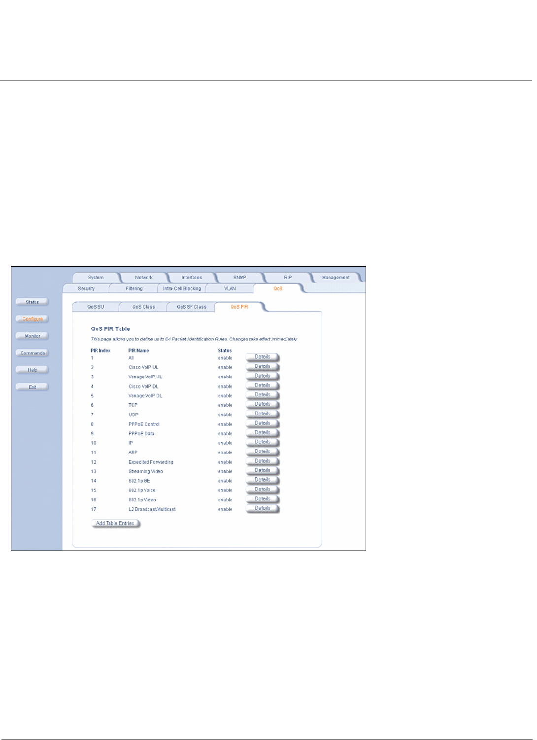
QoS PIR Configuration
Click Configure > QoS > QoS PIR Table. The 17 predefined PIRs are shown.
To view/edit the parameters of each PIR click on its Details button. You may enable, disable or delete any PIR entry by
clicking on the Status drop-down box and then clicking OK.
Configuration MP.11 4954-R Installation and Management
QoS (Quality of Service) Parameters
108
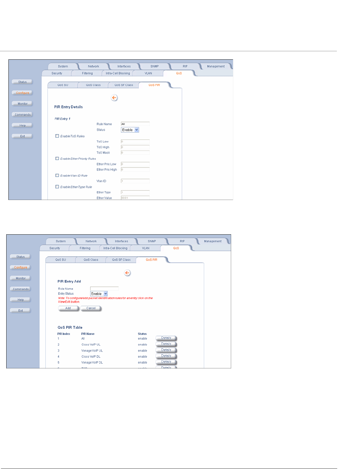
To add entries to the PIR Table, click the Add Table Entries button. Enter the Rule Name and select Enable or Disable
from the Entry Status drop-down box, then click Add to add the entry. Once the new entry appears on the screen (as
shown below), click its Details button to view/edit its parameters.
QoS SFC Configuration
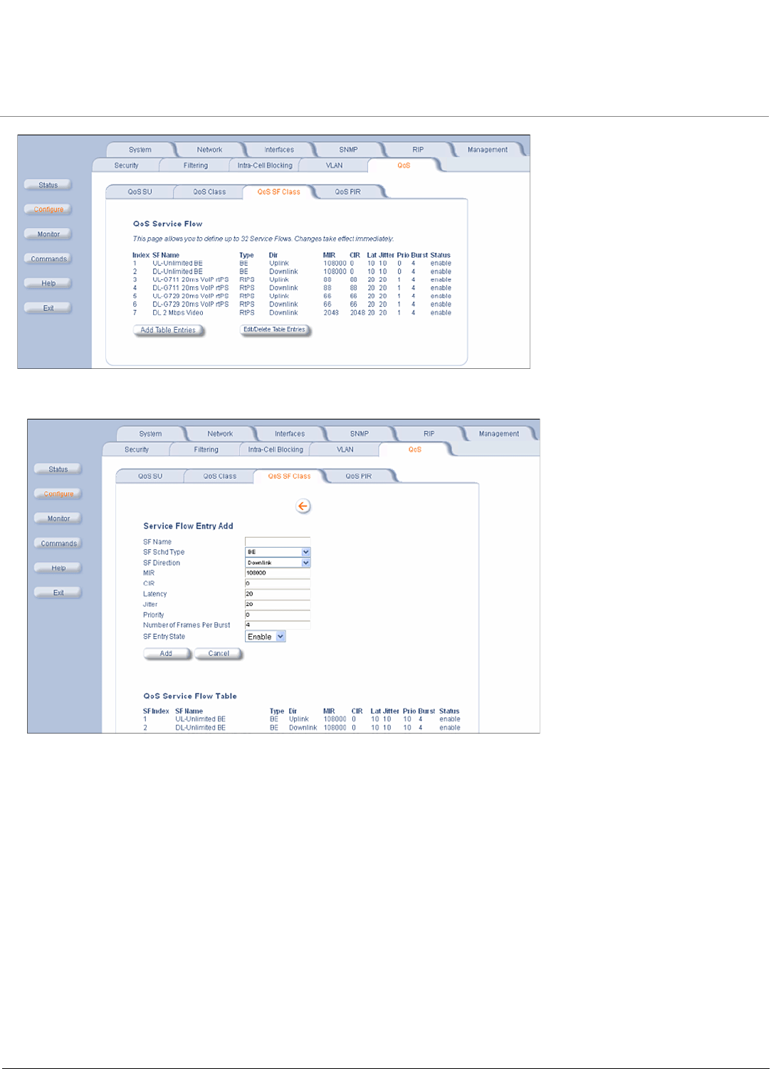
Click Configure > QoS > QoS SF Class. The 7 predefined SFCs are shown.
Configuration MP.11 4954-R Installation and Management
QoS (Quality of Service) Parameters
109
To add entries to the SFC Table, click the Add Table Entries button.
The following parameters are configurable:
•SF Name: Enter the name of the SF class you want to add.
•SF Schd Type: This field can be set to BE (Best Effort) or RtPS (Real-Time Polling Service).
•SF Direction: This field can be set to Downlink (traffic from BSU to SU) or Uplink (traffic from SU to BSU).
•MIR (Maximum Information Rate): The maximum sustained data rate specified in units of 1 Kbps from 8 Kbps up to
the maximum rate of 108000 Kbps per SU.
•CIR (Committed Information Rate): The minimum reserved traffic rate specified in units of 1 Kbps from 0 Kbps up to
the maximum rate of 10000 Kbps per SU.
•Latency: The maximum allowed latency specified in increments of 5 ms steps from a minimum of 5 ms up to a
maximum of 100 ms.
•Jitter: The maximum tolerable jitter specified in increments of 5 ms steps from a minimum of 0 ms up to the Maximum
Latency (in ms).
•Priority: The priority of this SFC from zero (0) to seven (7), 0 being the lowest, 7 being the highest.
•Number of Frames per Burst: The Maximum number of data messages in a Multi-Frame burst from one (1) to four
(4), which affects the percentage of the maximum throughput of the system according to following table.
Configuration MP.11 4954-R Installation and Management
QoS (Quality of Service) Parameters
110
•SF Entry State: This field can be set to Enable, Disable, or Delete.
Click Add to add the entry. The new entry will appear on the screen, taking up the next sequential index entry.
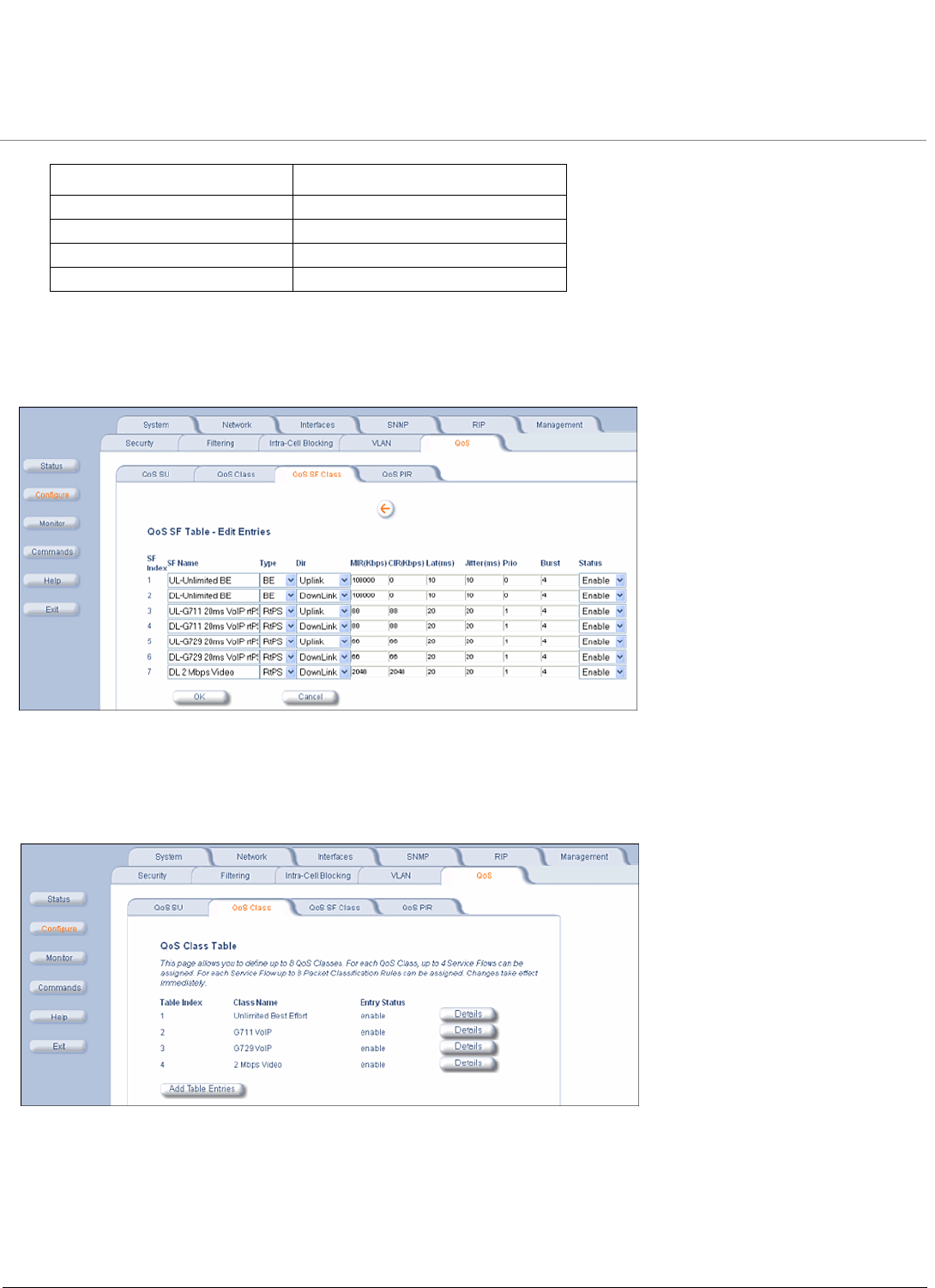
To make changes to the entries of the SFC Table, click the Edit/Delete Table Entries button.
Enter your changes and click OK. To delete an entry, click the Status drop-down box and select Delete, then click OK.
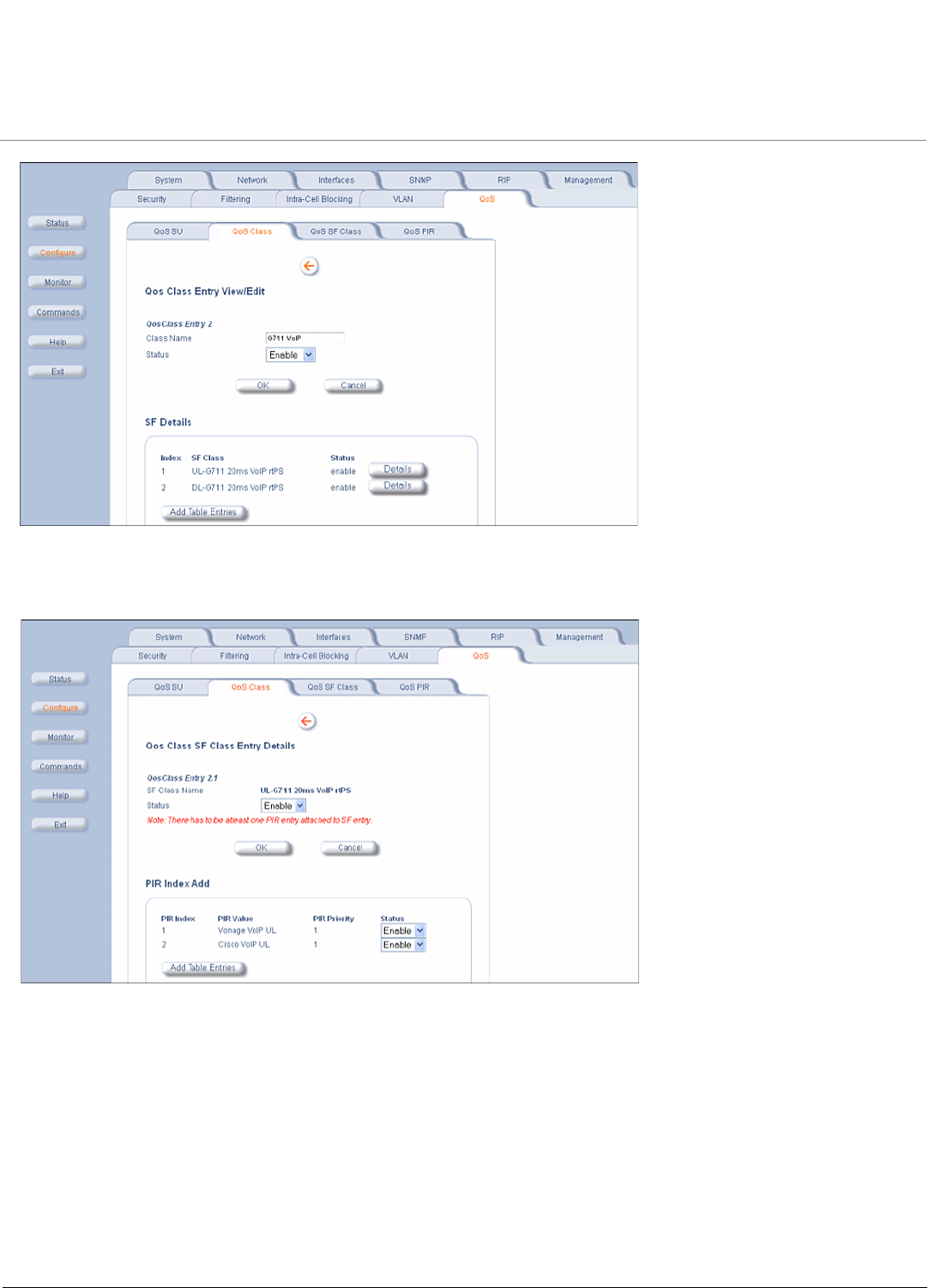
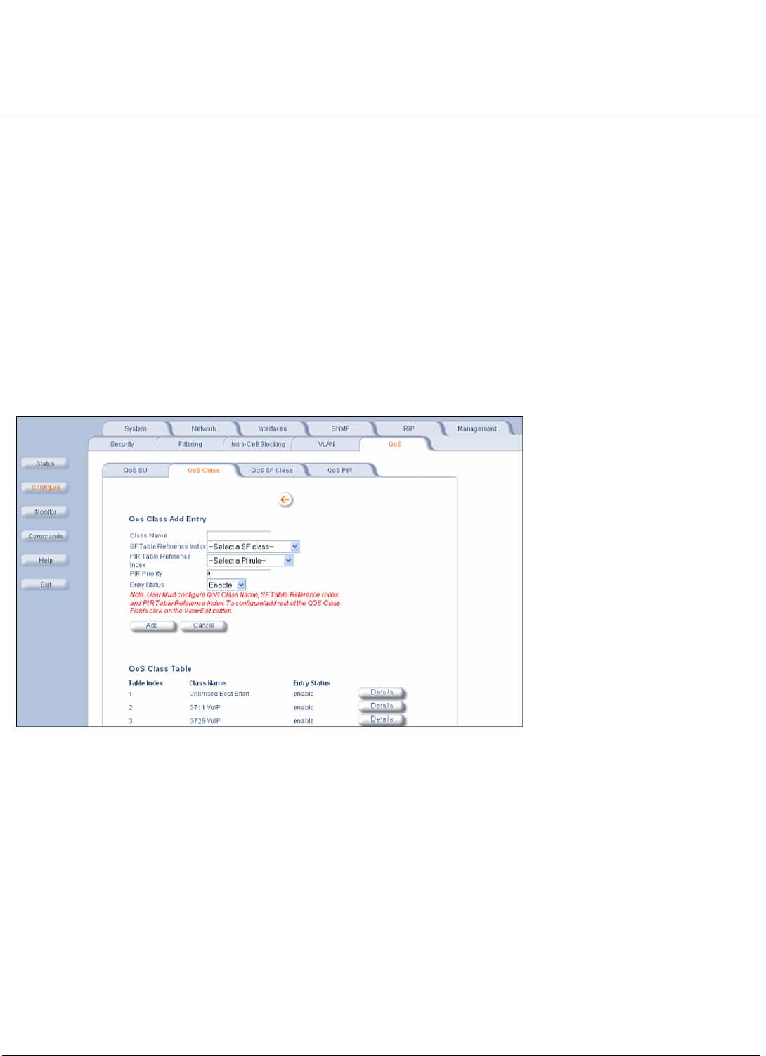
QoS Class Configuration
Click Configure > QoS > QoS Class. The 4 predefined QoS classes are shown.
To view/edit a QoS Class click on its Details button. You may enable, disable or delete this QoS Class entry by clicking
on the Status drop-down box and then clicking OK. You may also edit an existing SFC associated to this QoS class, or
add a new SFC.
No. of messages in a burst: % of the maximum throughput:
4 100%
3 97.6%
2 92.9%
1 76.2%
Configuration MP.11 4954-R Installation and Management
QoS (Quality of Service) Parameters
111
To edit an existing SFC associated to this QoS Class click its Details button. You may enable, disable or delete this SFC
entry by clicking on the Status drop-down box and then clicking OK. You may also delete a PIR associated to this SFC by
clicking on the Status drop-down box and then clicking OK, or add a new PIR to this SFC.
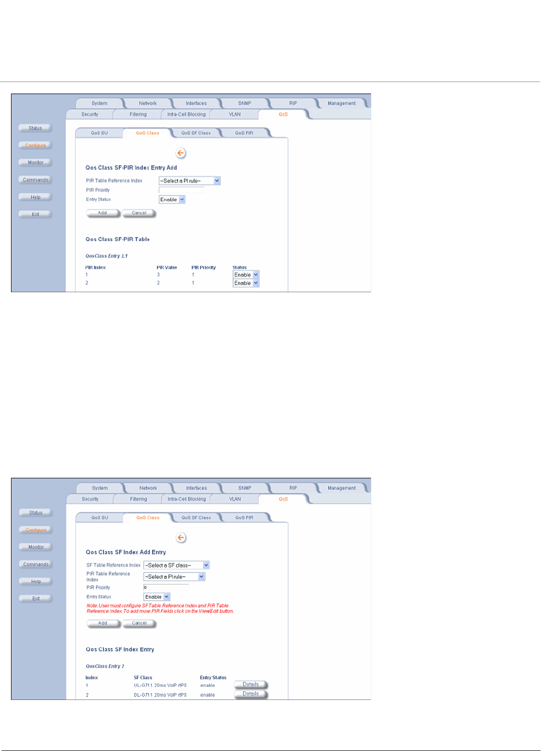
To add more PIRs to this SFC click the Add Table Entries button.
Configuration MP.11 4954-R Installation and Management
QoS (Quality of Service) Parameters
112
The following parameters are configurable:
•PIR Table Reference Index: Select one of the possible PIRs that have been previously configured from the drop-
down box.
•PIR Priority: This priority per rule defines the order of execution of PIRs during packet identification process. The PIR
priority is a number in the range 0-63, with priority 63 being executed first, and priority 0 being executed last. The PIR
priority is defined within a QoS class, and can be different for the same PIR in some other QoS class. If all PIRs within
one QoS class have the same priority, the order of execution of PIR rules will be defined by the order of definition of
SFCs, and by the order of definition of PIRs in each SFC, within that QoS class.
•Entry Status: This field is always set to Enable.
Click Add to add the entry. The new entry will show up on the screen taking up the next sequential index entry. You may
delete any PIR entry by clicking on the Status drop-down box.
Back on the QoS Class screen, click the Add Table Entries button to add a new SFC and associate it to this QoS Class.
The following parameters are configurable:
Configuration MP.11 4954-R Installation and Management
QoS (Quality of Service) Parameters
113
•SF Table Reference Index: Select one of the possible SFCs that have been previously configured from the drop-
down box to associate to this QoS Class.
•PIR Table Reference Index: Select one of the possible PIRs that have been previously configured from the drop-
down box to associate to this SFC.
•PIR Priority: This priority per rule defines the order of execution of PIRs during packet identification process. The PIR
priority is a number in the range 0-63, with priority 63 being executed first, and priority 0 being executed last. The PIR
priority is defined within a QoS class, and can be different for the same PIR in some other QoS class. If all PIRs within
one QoS class have the same priority, the order of execution of PIR rules will be defined by the order of definition of
SFCs, and by the order of definition of PIRs in each SFC, within that QoS class.
•Entry Status: This field is always set to Enable.
Click Add to add the entry. The new entry will show up on the screen taking up the next sequential index entry.
From this screen you may also edit an existing SFC by clicking on its Details button. This will take you back to the QoS
Class SF Class Entry Details.
Finally, to add a new QoS Class click the Add Table Entries button on the screen.
The following parameters are configurable:
•Class Name: Enter the name of the QoS class you want to add.
•SF Table Reference Index: Select one of the possible SFCs that have been previously configured from the drop-
down box to associate to this QoS Class.
•PIR Table Reference Index: Select one of the possible PIRs that have been previously configured from the drop-
down box to associate to this SFC.
•PIR Priority: This priority per rule defines the order of execution of PIRs during packet identification process. The PIR
priority is a number in the range 0-63, with priority 63 being executed first, and priority 0 being executed last. The PIR
priority is defined within a QoS class, and can be different for the same PIR in some other QoS class. If all PIRs within
one QoS class have the same priority, the order of execution of PIR rules will be defined by the order of definition of
SFCs, and by the order of definition of PIRs in each SFC, within that QoS class.
•Entry Status: This field is always set to Enable.
Click Add to add the entry. The new entry will show up on the screen taking up the next sequential index entry.
From this screen you may also edit an existing QoS Class by clicking on its Details button. This will take you to the QoS
Class Entry View/Edit screen.
Configuration MP.11 4954-R Installation and Management
QoS (Quality of Service) Parameters
114
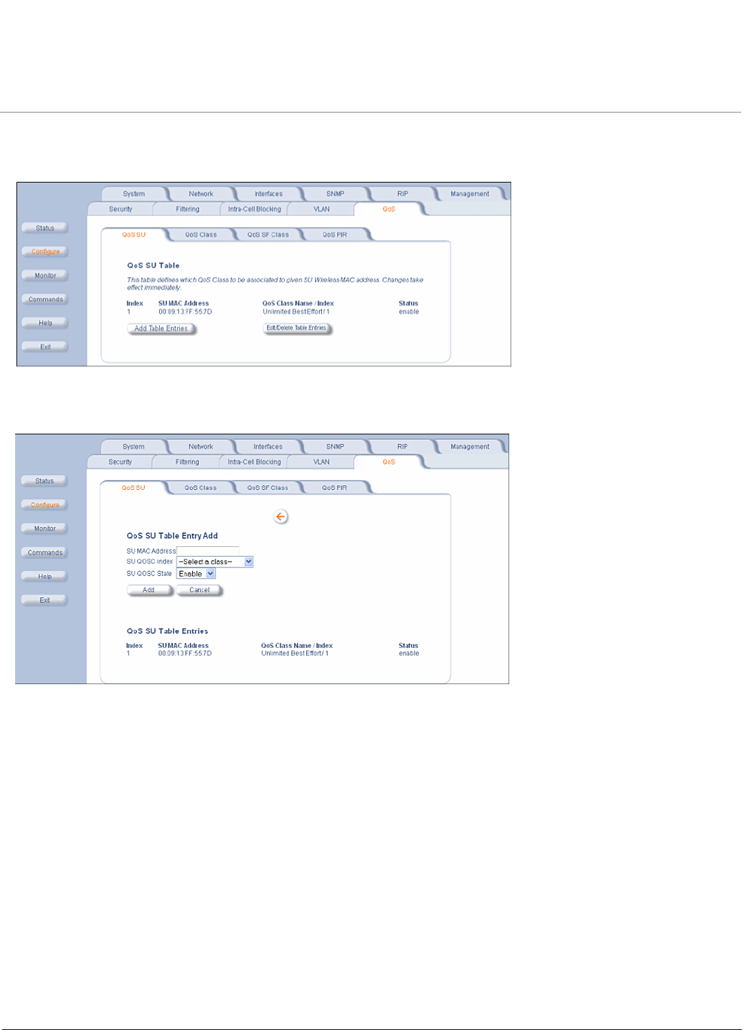
QoS SU Configuration
Click Configure > QoS > QoS SU.
This screen defines which QoS Classes will be associated to which given SUs by using their MAC addresses.
To add entries to the QoS SU Table, click the Add Table Entries button.
The following parameters are configurable:
•SU MAC Address: The MAC Address of the SU you want to associate to a specific QoS Class.
•SU QOSC Index: Select one of the possible QoS Classes that have been previously configured from the drop-down
box to associate to this SU.
•SU QOSC State: This field can be set to Enable, Disable, or Delete.
Click Add to add the entry. The new entry will show up on the screen taking up the next sequential index entry.
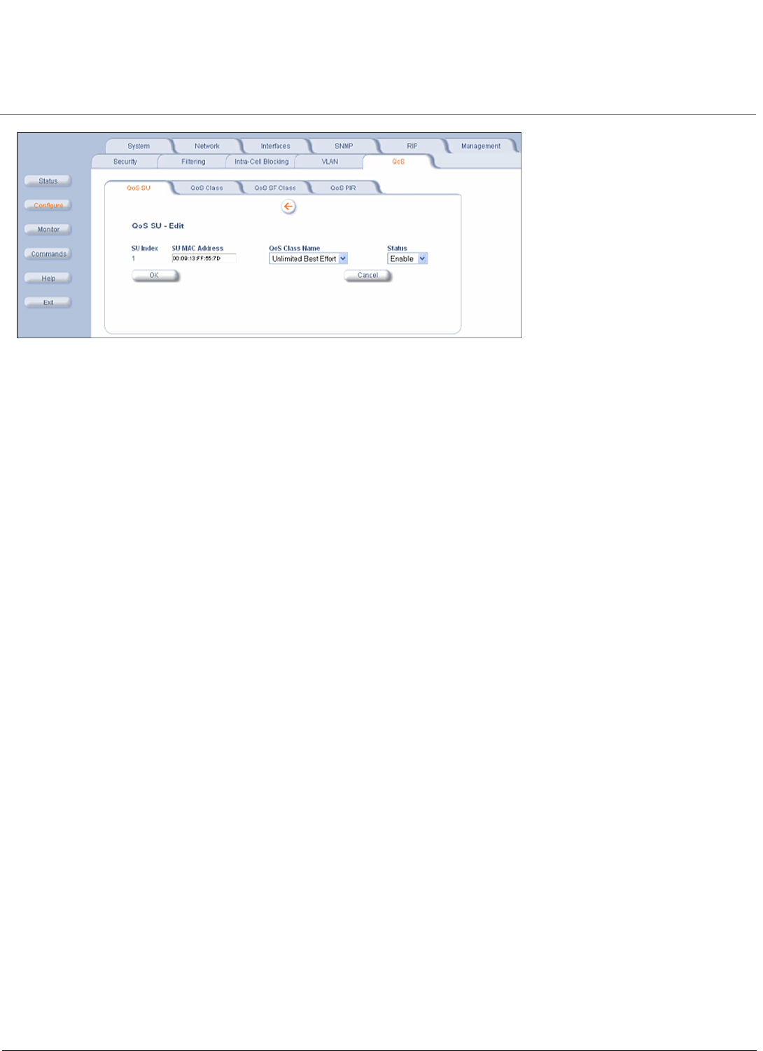
To make changes to QoS SU Table, click the Edit/Delete Table Entries button.
Configuration MP.11 4954-R Installation and Management
QoS (Quality of Service) Parameters
115
Enter your changes and click OK. To delete an entry, click the Status drop-down box and select Delete, then click OK.
Configuration MP.11 4954-R Installation and Management
SU Access to the Public Network (NAT)
116
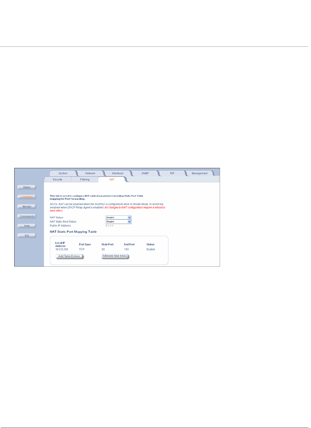
SU Access to the Public Network (NAT)
The NAT (Network Address Translation) feature lets hosts on the Ethernet side of the SU transparently access the public
network through the BSU. All hosts in the private network can have simultaneous access to the public network.
NOTE: The NAT tab is available for SUs in Routing mode only. The SU supports NAPT (Network Address Port
Translation) where all private IP addresses are mapped to a single public IP address, and does not support Basic
NAT (where private IP addresses are mapped to a pool of public IP addresses).
Both dynamic mapping (allowing private hosts to access hosts in the public network) and static mapping (allowing
public hosts to access hosts in the private network) are supported:
• In dynamic mapping, the SU maps the private IP addresses and its transport identifiers to transport identifiers of a
single Public IP address as they originate sessions to the public network. This is used only for outbound access.
• Static mapping is used to provide inbound access. The SU maps a private IP address and its local port to a fixed
public port of the global IP address. This is used to provide inbound access to a local server for hosts in the public
network. Static port mapping allows only one server of a particular type. Up to 1000 ports (500 UDP and 500 TCP) are
supported.
The following parameters are configurable:
NOTE: Changes to NAT parameters, including the NAT Static Port Mapping Table, require a reboot to take effect.
NOTE: When NAT is enabled, the DHCP Relay Agent feature is not supported (DHCP Relay Agent must be disabled
before NAT is enabled) and RIP updates are not sent or received. You can configure a DHCP server to allocate
IP addresses to hosts on the Ethernet side of the SU/ BSU (see Enable and Configure the DHCP Server).
•NAT Status: Enables or disables the NAT feature. NAT can be enabled only for SUs in Routing mode. The default is
disabled.
•NAT Static Bind Status: Enables or disables the NAT Static Bind status (static mapping) allowing public hosts to
access hosts in a private network. The default is disabled.
•Public IP Address: The NAT Public IP address is the wireless interface IP address.
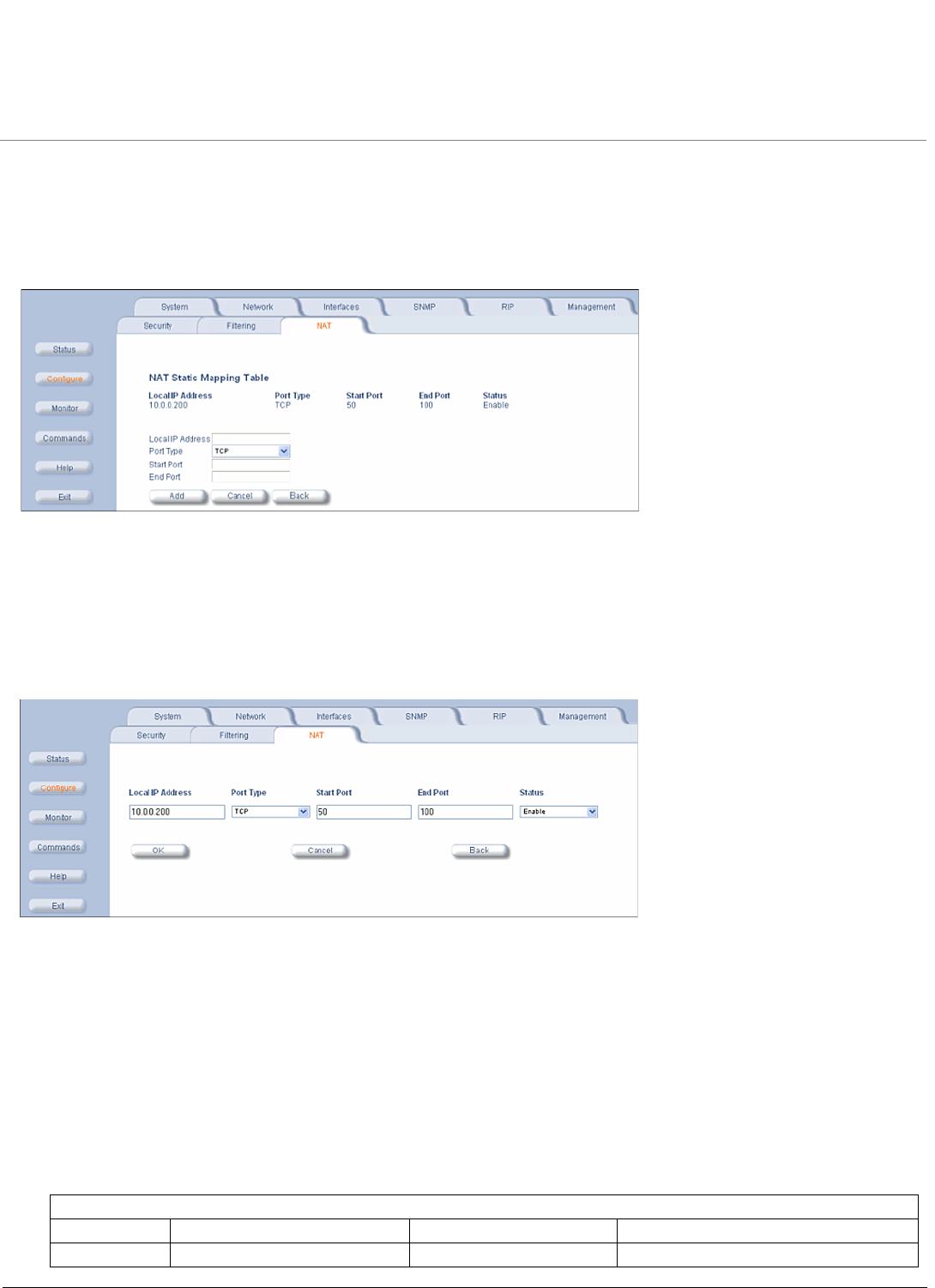
NAT Static Port Mapping Table
Adding entries to the NAT Static Mapping Table lets configured hosts in a private address realm on the Ethernet side of
the SU access hosts in the public network using Network Address Port Translation (NAPT). Up to 1000 entries can be
configured (500 UDP ports and 500 TCP ports).
Adding Entries
To add an entry:
Configuration MP.11 4954-R Installation and Management
SU Access to the Public Network (NAT)
117
1. Click the Add Table Entries button.
2. Enter the Local IP Address of the host on the Ethernet side of the SU.
3. Select the Port Type: TCP, UDP, or Both.
4. Enter the Start Port and End Port.
5. Click Add.
Editing Entries
To make changes to an entry:
1. Click the Edit/Delete Table Entries button.
2. Enter your changes. To delete an entry, click the Status drop-down box and select Delete
3. Click OK.
Supported Session Protocols
The NAT feature supports the following session protocols for both inbound and outbound access with the required
support, applications, and limitations given in the following table.
Certain Internet applications require an Application Level Gateway (ALG) to provide the required transparency for an
application running on a host in a private network to connect to its counterpart running on a host in the public network. An
ALG may interact with NAT to set up state information, use NAT state information, modify application specific payload and
perform the tasks necessary to get the application running across address realms.
No more than one server of a particular type is supported within the private network behind the SU.
These VPN protocols are supported with their corresponding ALGs: IPsec, PPTP, L2TP.
Supported Session Protocols
Protocol Support Applications Limitations
ICMP ICMP ALG Ping

Configuration MP.11 4954-R Installation and Management
SU Access to the Public Network (NAT)
118
FTP FTP ALG File transfer
H.323 H.323 ALG Multimedia conferencing
HTTP Port mapping for inbound
connection.
Web browser
TFTP Port mapping for inbound
connection.
File transfer
Telnet Port mapping for inbound
connection.
Remote login
CUSeeMe Port mapping for inbound and
outbound connection.
Video conferencing One user is allowed for video
conferencing
IMAP Port mapping for inbound
connection.
Mail
PNM Port mapping for inbound
connection.
Streaming media with
Real Player
POP3 Port mapping for inbound
connection.
E-mail
SMTP Port mapping for inbound
connection.
E-mail Mails with IP addresses of MTAs or
using IP addresses in place of FQDN
are not supported (requires SMTP
ALG).
RTSP Port mapping for inbound
connection.
Streaming audio/video
with Quick Time and Real
Player
ICQ Port mapping for inbound
connection.
Chat and file transfer Each host using ICQ needs to be
mapped for different ports.
IRC Port mapping for inbound
connection.
Chat and file transfer Each host using IRC needs to be
mapped for different ports.
MSN
Messenger
Port mapping for inbound and
outbound connection.
Conference and Share
files with Net meeting
Only one user is allowed for net
meeting.
Net2Phone Port mapping for inbound and
outbound connection.
Voice communication
IP Multicast Pass Through Multicasting
Stream works Port mapping for inbound
connection.
Streaming video
Quake Port mapping for inbound
connection.
Games When a Quake server is configured
within the private network behind a
SU, the SU cannot provide information
about that server on the public
network.
Also, certain Quake servers do not let
multiple users log in using the same IP
address, in which case only one
Quake user is allowed.
Supported Session Protocols
Protocol Support Applications Limitations

MP.11 4954-R Installation and Management
119
7
Monitoring
This chapter describes using the Web interface to obtain detailed information about the settings and performance of the
unit.
Click the Monitor button to access this information.
The following tabs appear in the Monitor section:
•Wireless
•ICMP
•Per Station
•Features
•Link Test
•Interfaces
•IP ARP Table
•IP Routes
•Learn Table
•RIP
•RADIUS
•QoS
•Temperature
NOTE: The Radius tab is available on BSUs only. The RIP tab is relevant only in Routing mode.
Help and Exit buttons also appear on each page of the Web interface; click the Help button to access online help; click
the Exit button to exit the application.
For an introduction to the basics of management, see Basic Management.
Monitoring MP.11 4954-R Installation and Management
Wireless
120
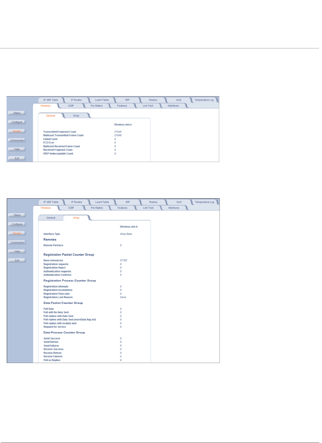
Wireless
General Performance
Click Monitor > Wireless > General to monitor the general performance of the wireless interface.
WORP Interface Performance
Click Monitor > Wireless > WORP tab to monitor the performance of the WORP Base or WORP SU interfaces.
The Registration Last Reason field indicates either a successful registration (a value of 1) or it indicates the reason why
the last registration failed. Possible values for the Registration Last Reason field are as follows:
• None (successful registration)
• Maximum number of SUs reached
• Authentication failure
• Roaming
• No response from SU within the Registration Timeout Period
• Low Signal Quality
Monitoring MP.11 4954-R Installation and Management
ICMP
121
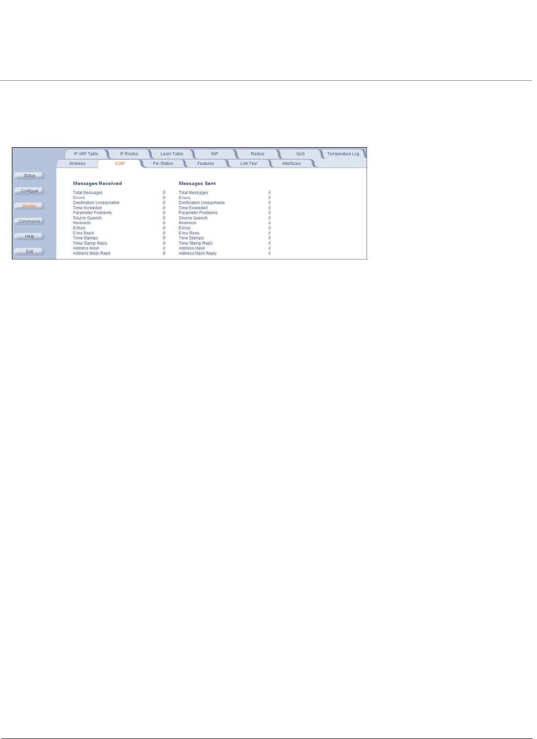
ICMP
Click Monitor > ICMP to view the number of ICMP messages sent and received by the unit. It includes ping, route, and
host unreachable messages.
Monitoring MP.11 4954-R Installation and Management
Per Station
122
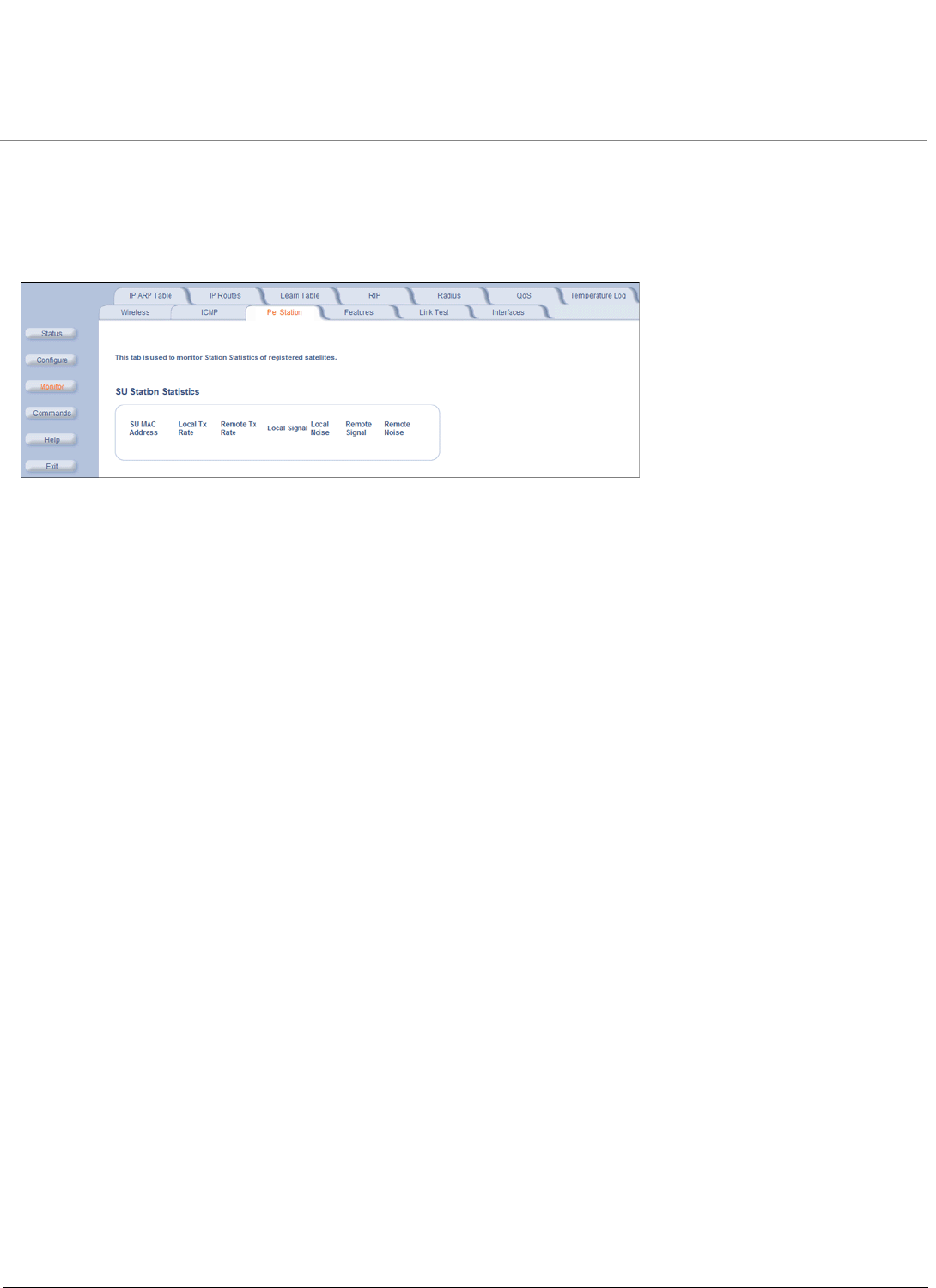
Per Station
Click Monitor > Per Station to view Station Statistics. On the SU, the “Per Station” page shows statistics of the BSU to
which the SU is registered. On the BSU, it shows statistics of all the SU’s connected to the BSU.
The page’s statistics refresh every 4 seconds.
Monitoring MP.11 4954-R Installation and Management
Features
123
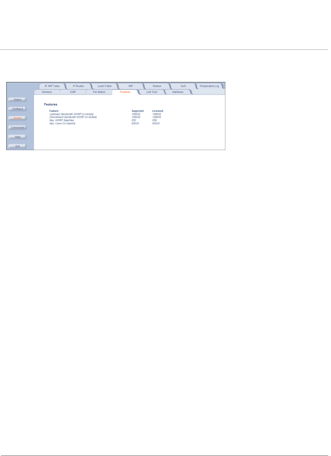
Features
Click Monitor > Features to view the following information.
NOTE: A BSU shows how many WORP SUs it can support; the SU shows how many Ethernet hosts it supports on its
Ethernet port as the “Max Users on Satellite” parameter.
Monitoring MP.11 4954-R Installation and Management
Link Test
124
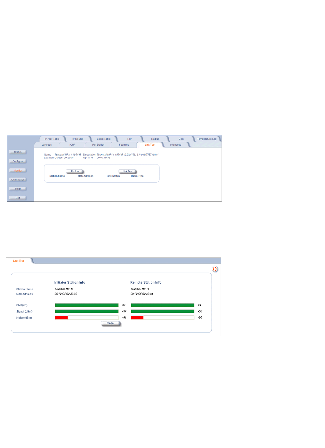
Link Test
Click Monitor > Link Test to find out which wireless stations are in range and to check their link quality.
NOTE: Link Test requires Internet Explorer version 6.0 or later. Earlier versions do not support Link Test.
Link Test for the unit reports the Signal-to-Noise Ratio (SNR) value in dB; the higher this number, the better the signal
quality. Furthermore, it reports the signal level and noise level in dBm. The latter two are approximations of the level at
which the unit receives the signal of the peer unit and the background noise.
• Clicking Explore from a BSU displays all its registered SUs.
• Clicking Explore from an SU displays only the BSU with which it is registered.
All stations displayed after “Explore” come up “Disabled.” Select a station by changing Disabled to Start and click the
Link Test button. You can change multiple stations to Start, but only the last station in the list is displayed as the remote
partner when you click the Link Test button.
The Link Test provides SNR, Signal, and Noise information for both, the local and the remote unit’s levels. Link Test stops
when you close the Link Test page.
Monitoring MP.11 4954-R Installation and Management
Interfaces
125
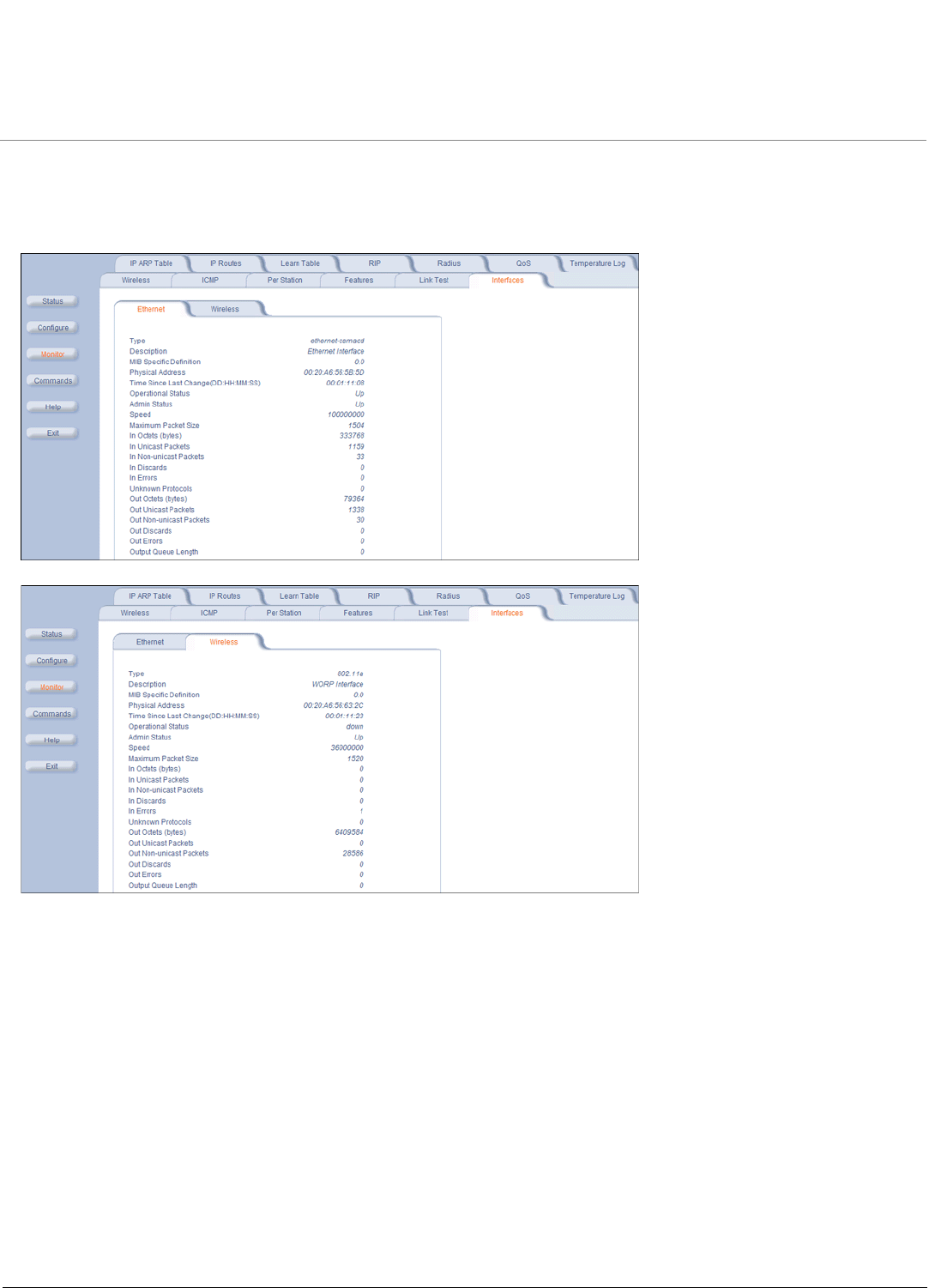
Interfaces
Click Monitor > Interfaces to view detailed information about the IP-layer performance of the unit’s interfaces. There are
two sub-tabs: Wireless and Ethernet. The following figures show both interfaces.
Monitoring MP.11 4954-R Installation and Management
IP ARP Table
126
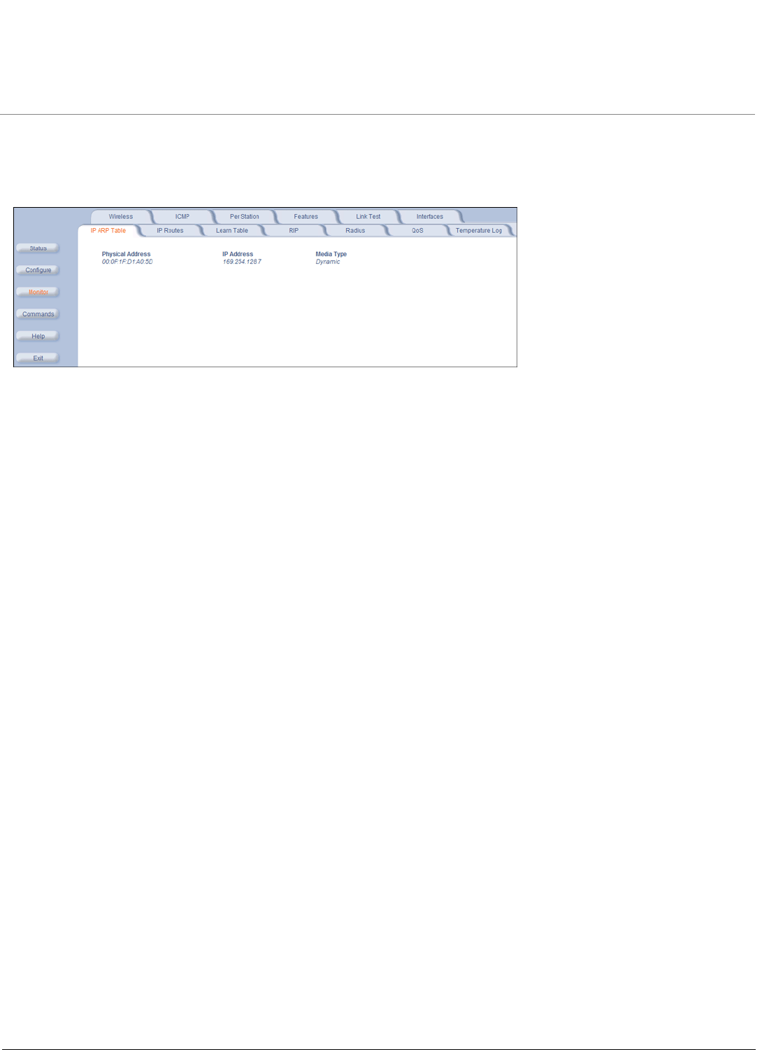
IP ARP Table
Click Monitor > IP ARP Table to view the mapping of the IP and MAC addresses of all radios registered at the BSU. This
information is based upon the Address Resolution Protocol (ARP).
Monitoring MP.11 4954-R Installation and Management
IP Routes
127
IP Routes
Click Monitor > IP Routes to view all active IP routes of the unit. These can be either static or dynamic (obtained
through RIP). This tab is available only in Routing mode, and you can add routes only when in Routing mode.
Monitoring MP.11 4954-R Installation and Management
Learn Table
128
Learn Table
Click Monitor > Learn Table to view all MAC addresses the unit has detected on an interface. The Learn Table displays
information relating to network bridging. It reports the MAC address for each node that the device has learned is on the
network and the interface on which the node was detected. There can be up to 10,000 entries in the Learn Table. This tab
is only available in Bridge mode.
Monitoring MP.11 4954-R Installation and Management
RIP
129
RIP
Click Monitor > RIP to view Routing Internet Protocol data for the Ethernet and Wireless interfaces.
Monitoring MP.11 4954-R Installation and Management
RADIUS
130
RADIUS
Click Monitor > Radius to view information about the traffic exchanged with a RADIUS server.
Monitoring MP.11 4954-R Installation and Management
QoS
131
QoS
Click Monitor > QoS to view summary information about the Quality of Service per BSU and for each SU registered with
that BSU.
This tab is available only on the BSU.
Monitoring MP.11 4954-R Installation and Management
Temperature
132
Temperature
The feature for reporting and logging internal unit temperature observes and reports the internal temperature of the unit.
Temperature is logged and an SNMP trap sent when the internal temperature crosses the limit of 0ºC to 55ºC (at 5
degrees before the limit, the unit issues a warning trap).
You can select a recording interval from one to sixty minutes, in 5-minute increments on the Configure: System tab. A
log file holds the recorded data. The log can hold at least 576 entries (two days with the refresh time of 5 minutes). For
further analysis, the log can be exported to a text file with a new line feed as a line separator.
The Temperature Log contains two sub-tabs:
•The Current Temperature tab indicates the unit’s current temperature. The current temperature value is refreshed
every 4 seconds.
•The Log tab keeps track of the temperature recorded at the end of each configured logging interval. You can reset or
refresh the log using the Reset and Refresh buttons.
MP.11 4954-R Installation and Management
133
8
Commands
This chapter describes the commands that you can issue with the Web Interface.
Click the Commands button to access available commands. See the following:
• Download (see Download Files)
• Upload (see Upload Files)
• Downgrade (see Downgrade to Previous Release)
• Reboot (see Reboot the Unit)
• Reset (see Reset the Unit to Factory Default)
• Help Link (see Set the Help Link Location)
Help and Exit buttons also appear on each page of the Web interface; click the Help button to access online help; click
the Exit button to exit the application.
For an introduction to the basics of management, see Basic Management.
Download Files
Click Commands > Download tab to download configuration, image and license files to the unit via a TFTP server (see
TFTP Server Setup for information about the SolarWinds TFTP server software located on your product installation CD).
The following parameters may be configured or viewed:
•Server IP address: Enter the TFTP Server IP address.
•File Name: Enter the name of the file to be downloaded. If you are using the SolarWinds TFTP server software
located on your product installation CD, the default directory for downloading files is C:\TFTP-Root.
•File Type: Choose either Config, image, BspBl, or license.
•File Operation: Choose either Download or Download and Reboot.
Click OK to start the download.
Commands MP.11 4954-R Installation and Management
Upload Files
134
Upload Files
Click Commands > Upload to upload a configuration or log file from the unit to a TFTP server (see TFTP Server Setup
for information about the SolarWinds TFTP server software located on your product installation CD).
The following parameters may be configured or viewed:
•Server IP address: Enter the TFTP Server IP address.
•File Name: Enter the name of the file to be uploaded. If you are using the SolarWinds TFTP server software located
on your product installation CD, the default directory for uploading files is C:\TFTP-Root.
•File Type: Choose either Config, Templog, or Eventlog.
Click OK to start the upload.
Commands MP.11 4954-R Installation and Management
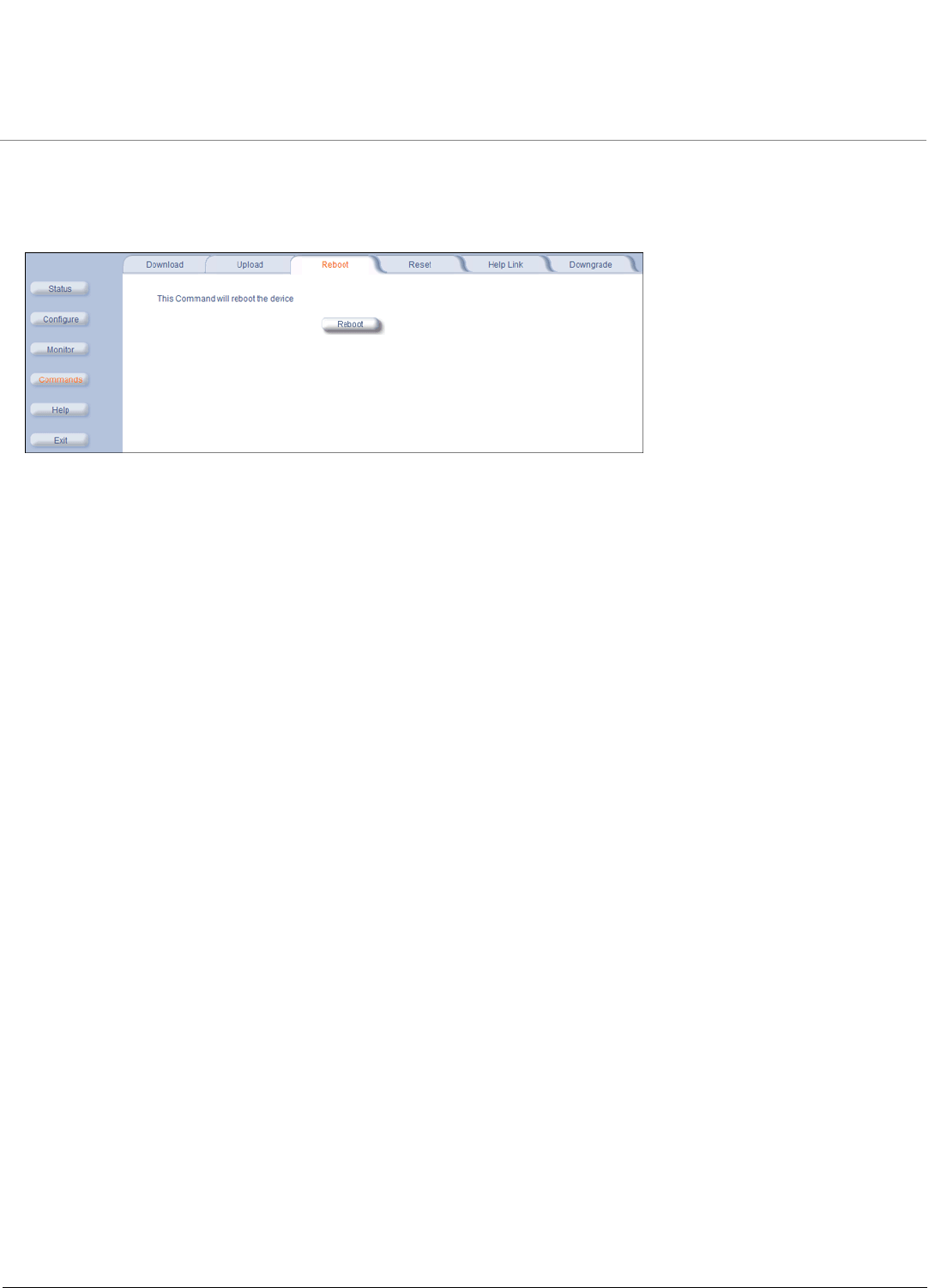
Reboot the Unit
135
Reboot the Unit
Click Commands > Reboot to reboot the unit’s embedded software. Configuration changes are saved and the unit is
reset.
CAUTION: Rebooting the unit causes all users currently connected to lose their connection to the network until the unit
has completed the reboot process and resumed operation.
Commands MP.11 4954-R Installation and Management
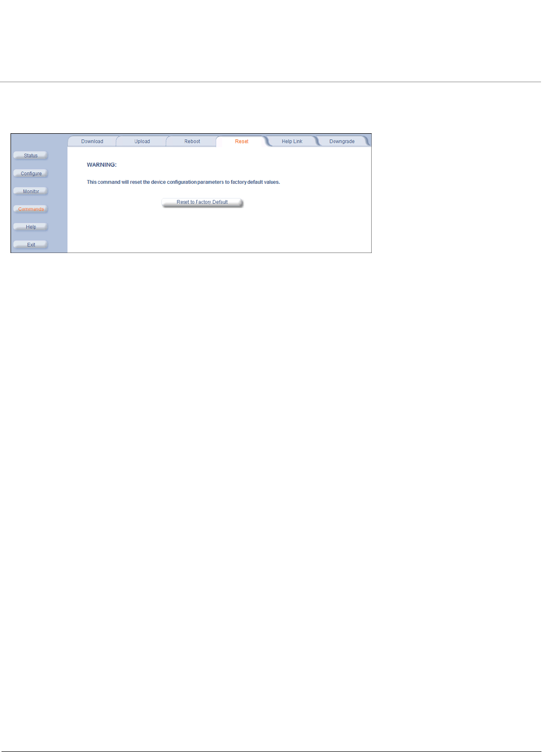
Reset the Unit to Factory Default
136
Reset the Unit to Factory Default
Click Commands > Reset to restore the configuration of the unit to the factory default values.
You can also reset the unit by pressing the RELOAD button located on the side of the power brick. See Hard Reset to
Factory Default for more information.
CAUTION: Resetting the unit to its factory default configuration permanently overwrites all changes made to the unit.
The unit reboots automatically after this command has been issued.
Commands MP.11 4954-R Installation and Management
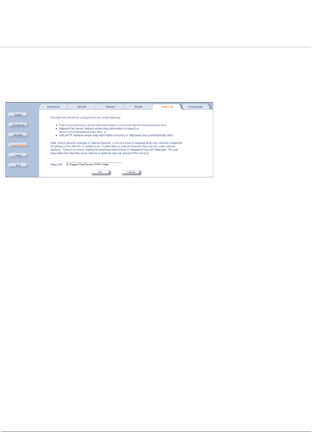
Set the Help Link Location
137
Set the Help Link Location
Click Commands > Help Link to set the location of the help files of the Web Interface. Upon installation, the help files are
installed in the C:\Program Files\Tsunami\MP.11 [Product Name]\Help folder.
If you want to place these files on a shared drive, copy the Help folder to the new location and specify the new path in the
Help Link box.
Commands MP.11 4954-R Installation and Management
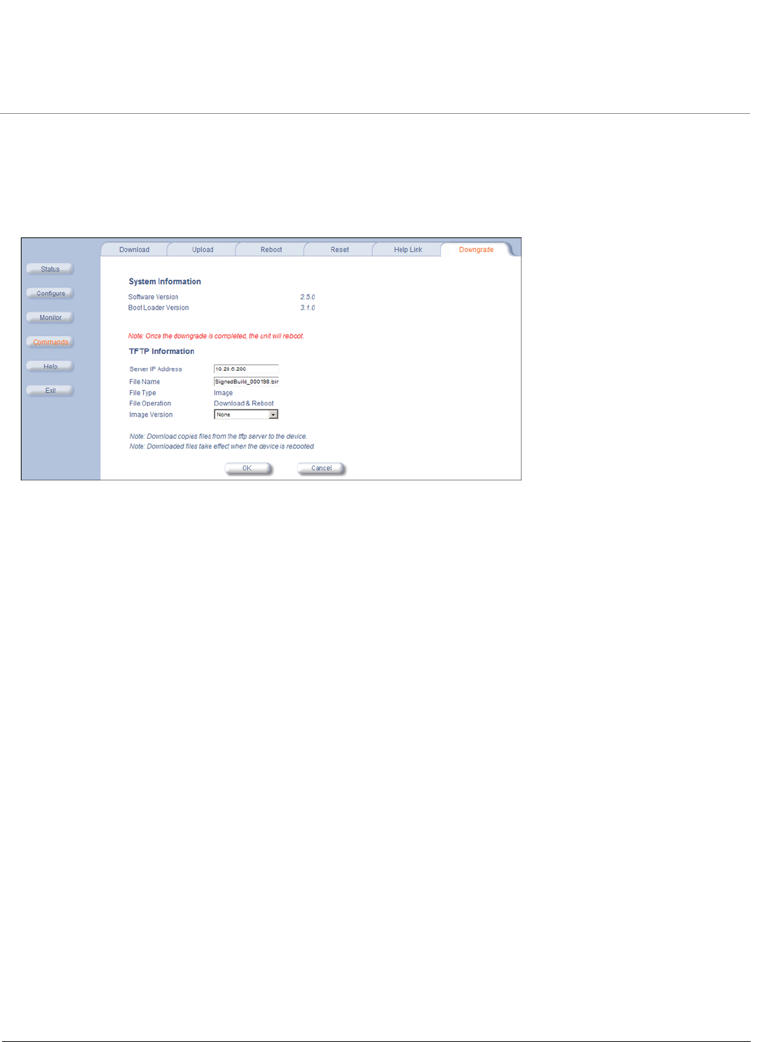
Downgrade to Previous Release
138
Downgrade to Previous Release
Click Commands > Downgrade to downgrade to a previous release. Downgrade currently is supported only to release
2.0.1 and later. Once you enter this command, the unit is downgraded to the specified release and is automatically
rebooted. The filename specified and the filename of the image selected for downgrade must be the same version. The
unit will download the file, re-format the configuration to match the version, and reboot to put the image into effect.

MP.11 4954-R Installation and Management
139
9
Procedures
This chapter describes the following procedures:
•TFTP Server Setup: Prepares the TFTP server for transferring files to and from the unit. This procedure is used by
the other procedures that transfer files.
•Web Interface Image File Download: Upgrades the embedded software.
•Configuration Backup: Saves the configuration of the unit.
•Configuration Restore: Restores a previous configuration through configuration file download.
•Soft Reset to Factory Default: Resets the unit to the factory default settings through the Web or Command Line
Interface.
•Hard Reset to Factory Default: In some cases, it may be necessary to revert to the factory default settings (for
example, if you cannot access the unit or you lost the password for the Web Interface).
•Forced Reload: Completely resets the unit and erases the embedded software. Use this procedure only as a last
resort if the unit does not boot and the “Hard Reset to Factory Default” procedure did not help. If you perform a
Forced Reload, you must download a new image file as described in Image File Download with the Bootloader.
•Image File Download with the Bootloader: If the unit does not contain embedded software, or the embedded software
is corrupt, you can use this procedure to download a new image file.

Procedures MP.11 4954-R Installation and Management
TFTP Server Setup
140
TFTP Server Setup
A Trivial File Transfer Protocol (TFTP) server lets you transfer files across a network. You can upload files from the unit
for backup or copying, and you can download the files for configuration and image upgrades. The SolarWinds TFTP
server software is located on the product installation CD, or can be downloaded from http://support.proxim.com. You can
also download the latest TFTP software from SolarWind’s Web site at http://www.solarwinds.net. The instructions that
follow assume that you are using the SolarWinds TFTP server software; other TFTP servers may require different
configurations.
NOTE: If a TFTP server is not available in the network, you can perform similar file transfer operations using the HTTP
interface.
To download or upload a file, you must connect to the computer with the TFTP server through the unit’s Ethernet port.
This can be any computer in the network or a computer connected to the unit with a cross-over Ethernet cable. For
information about installing the TFTP server, see Step 13: Install Documentation and Software.
Ensure that:
1. The upload or download directory is correctly set (the default directory is C:\TFTP-Root).
2. The required image file is present in the directory.
3. The TFTP server is running. The TFTP server must be running only during file upload and download. You can
check the connectivity between the unit and the TFTP server by pinging the unit from the computer that hosts the
TFTP server. The ping program should show replies from the unit.
4. The TFTP server is configured to both Transmit and Receive files (on the Security tab under File > Configure), with
no automatic shutdown or time-out (on the Auto-Close tab).

Procedures MP.11 4954-R Installation and Management
Web Interface Image File Download
141
Web Interface Image File Download
In some cases, it may be necessary to upgrade the embedded software of the unit by downloading an image file. To
download an image file through the Web Interface:
1. Set up the TFTP server as described in TFTP Server Setup.
2. Access the unit as described in Logging in to the Web Interface.
3. Click Commands > Download tab.
4. Fill in the following details:
•Server IP Address <IP address TFTP server>
•File Name <image file name>
•File Type Image
•File Operation Download
5. Click OK to start the file transfer.
The unit downloads the image file. The TFTP server program should show download activity after a few seconds. When
the download is complete, the unit is ready to start the embedded software upon reboot.

Procedures MP.11 4954-R Installation and Management
Configuration Backup
142
Configuration Backup
You can back up the unit’s configuration by uploading the configuration file. You can use this file to restore the
configuration or to configure another unit (see Configuration Restore).
To upload a configuration file through the Web Interface:
1. Set up the TFTP server as described in TFTP Server Setup.
2. Access the unit as described in Logging in to the Web Interface.
3. Click Commands > Upload.
4. Fill in the following details:
•Server IP Address <IP address TFTP server>
•File Name <configuration file name>
•File Type Config
•File Operation Upload
5. Click OK to start the file transfer.
The unit uploads the configuration file. The TFTP server program should show upload activity after a few seconds. When
the upload is complete, the configuration is backed up.

Procedures MP.11 4954-R Installation and Management
Configuration Restore
143
Configuration Restore
You can restore the configuration of the unit by downloading a configuration file. The configuration file contains the
configuration information of a unit.
To download a configuration file through the Web Interface:
1. Set up the TFTP server as described in TFTP Server Setup.
2. Access the unit as described in Logging in to the Web Interface.
3. Click Commands > Download tab.
4. Fill in the following details:
•Server IP Address <IP address TFTP server>
•File Name <configuration file name>
•File Type Config
•File Operation Download
5. Click OK to start the file transfer.
The unit downloads the configuration file. The TFTP server program should show download activity after a few seconds.
When the download is complete and the system rebooted, the configuration is restored.

Procedures MP.11 4954-R Installation and Management
Soft Reset to Factory Default
144
Soft Reset to Factory Default
If necessary, you can reset the unit to the factory default settings. Resetting to default settings means that you must
configure the unit anew.
To reset to factory default settings using the Web Interface:
1. Click Commands > Reset.
2. Click the Reset to Factory Default button.
The device configuration parameter values are reset to their factory default values.
If you do not have access to the unit, you can use the procedure described in “Hard Reset to Factory Default” below as
an alternative.

Procedures MP.11 4954-R Installation and Management
Hard Reset to Factory Default
145
Hard Reset to Factory Default
If you cannot access the unit or you have lost its password, you can reset the unit to the factory default settings. Resetting
to default settings means you must configure the unit anew.
To reset to factory default settings, press and hold the RELOAD button on the side of the unit’s power supply for a
minimum of 5 seconds but no more than 10 seconds. The configuration is deleted from the unit and the unit reboots,
writing and using a default configuration.
CAUTION: It you hold the RELOAD button for longer than 20 seconds, you may go into Forced Reload mode, which
erases the unit’s embedded software. This software image must be reloaded through an Ethernet
connection with a TFTP server. The image filename to be downloaded can be configured with either
ScanTool through the Ethernet interface or with the Boot Loader CLI through the serial port to make the unit
functional again.

Procedures MP.11 4954-R Installation and Management
Forced Reload
146
Forced Reload
With Forced Reload, you erase the embedded software. Use this procedure only as a last resort if the unit does not boot
and the “Reset to Factory Defaults” procedure did not help. If you perform a Forced Reload, you must download a new
image file with the Bootloader (see “Image File Download with the Bootloader” below).
CAUTION: The following procedure erases the embedded software of the unit. This software image must be reloaded
through an Ethernet connection with a TFTP server. The image filename to be downloaded can be
configured with ScanTool through the Ethernet interface to make the unit functional again.
To do a forced reload:
1. Disconnect and reconnect power to the unit; the unit resets and the LEDs flash.
2. Immediately press and hold the RELOAD button on the side of the unit’s power supply for about 20 seconds. The
software image and configuration are deleted from the unit.
3. Follow the Image File Download with the Bootloader procedure to download an image file.

Procedures MP.11 4954-R Installation and Management
Image File Download with the Bootloader
147
Image File Download with the Bootloader
The following procedures download an image file to the unit after the embedded software has been erased with Forced
Reload or when the embedded software cannot be started by the Bootloader. A new image file can be downloaded to the
unit with ScanTool, or the Command Line Interface through the unit’s serial port. In both cases, the file is transferred
through Ethernet with TFTP. Because the CLI serial port option requires a serial RS-232C cable, Proxim recommends the
ScanTool option.
Download with ScanTool
To download an image file with the ScanTool:
1. Set up the TFTP server as described in TFTP Server Setup.
2. Run ScanTool on a computer that is connected to the same LAN subnet as the unit. ScanTool scans the subnet for
units and displays the found units in the main window. If in Forced Reload, ScanTool does not find the device until the
unit Bootloader times out from its default operation to download an image. Click Rescan to re-scan the subnet and
update the display until the unit shows up in Bootloader mode.
3. Select the unit to which you want to download an image file and click Change.
4. Ensure that IP Address Type Static is selected and fill in the following details:
• Password
• IP Address and Subnet Mask of the unit.
•TFTP Server IP Address and, if necessary, the Gateway IP Address of the TFTP server.
•Image File Name of the file with the new image.
5. Click OK to start the file transfer.
The unit downloads the image file. The TFTP server program should show download activity after a few seconds. When
the download is complete, the LED pattern should return to reboot state. The unit is ready to start the embedded
software.
After a Forced Reload procedure, the unit returns to factory default settings and must be reconfigured. ScanTool can be
used to set the system name and IP address.
To access the unit, see Logging in to the Web Interface.
Download with CLI
To use the CLI through the serial port of the unit, you need a connector cable with a male RJ11 and a female DB9
connector (included with the unit) and an ASCII terminal program such as HyperTerminal. Proxim recommends you
switch off the unit and the computer before connecting or disconnecting the serial RS-232C cable.
To download an image file:
1. Set up the TFTP server as described in TFTP Server Setup.
2. Start the terminal program (such as HyperTerminal), set the following connection properties, and then connect:
• COM port: for example, COM1 or COM2 to which the unit serial port is connected)
• Bits per second: 9600
• Data bits: 8
• Stop bits: 1
• Flow control: None
• Parity: None
3. Disconnect and reconnect power to reset the unit; the terminal program displays Power On Self Test (POST)
messages.

Procedures MP.11 4954-R Installation and Management
Image File Download with the Bootloader
148
4. When the “Sending Traps to SNMP manager periodically” message is displayed (after about 30 seconds), press
the ENTER key.
5. The command prompt is displayed; enter the following commands:
set ipaddr <IP address nit>
set ipsubmask <subnet mask>
set ipaddrtype static
set tftpipaddr <IP address TFTP server>
set tftpfilename <image file name>
set ipgw <gateway IP address>
reboot
For example:
set ipaddr 10.0.0.12
set ipsubmask 255.255.255.0
set ipaddrtype static
set tftpipaddr 10.0.0.20
set tftpfilename image.bin
set ipgw 10.0.0.30
reboot
The unit reboots and downloads the image file. The TFTP server program should show download activity after a few
seconds. When the download is complete, the unit is ready for configuration.
To access the unit, see Logging in to the Web Interface. Note that the IP configuration in normal operation differs from the
IP configuration of the Boot Loader.

MP.11 4954-R Installation and Management
149
10
Troubleshooting
This chapter helps you to isolate and solve problems with your unit. In the event this chapter does not provide a solution,
or the solution does not solve your problem, check our support website at http://support.proxim.com.
Before you start troubleshooting, it is important that you have checked the details in the product documentation. For
details about RADIUS, TFTP, terminal and telnet programs, and Web browsers, refer to their appropriate
documentation.
In some cases, rebooting the unit clears the problem. If nothing else helps, consider a Soft Reset to Factory Default or a
Forced Reload. The Forced Reload option requires you to download a new image file to the unit.
See the following:
•Connectivity Issues
•Communication Issues
•Setup and Configuration Issues
•VLAN Operation Issues
•Link Problems
Connectivity Issues
The issues described in this section relate to the connections of the unit.
Unit Does Not Boot
The unit shows no activity (the power LED is off).
1. Ensure that the power supply is properly working and correctly connected.
2. Ensure that all cables are correctly connected.
3. Check the power source.
4. If you are using an Active Ethernet splitter, ensure that the voltage is correct.
Serial Link Does Not Work
The unit cannot be reached through the serial port.
1. Check the cable connection between the unit and the computer.
2. Ensure that the correct COM port is used.
3. Start the terminal program; set the following connection properties (also see “HyperTerminal Connection Properties”
in the Tsunami MP.11 Reference Manual), and then connect.
• COM port: for example, COM1 or COM2 to which the unit serial port is connected)
• Bits per second: 9600
• Data bits 8
• Stop bits: 1
• Flow control: None
• Parity: None
4. Ensure that the unit and the computer use the same serial port configuration parameters.

Troubleshooting MP.11 4954-R Installation and Management
Connectivity Issues
150
5. Disconnect and reconnect power to reset the unit. The terminal program displays Power On Self Tests (POST)
messages and displays the following after approximately 90 seconds: Please enter password:
HyperTerminal Connection Problems
The serial connection properties can be found in HyperTerminal as follows:
1. Start HyperTerminal and select Properties from the File menu.
2. Select Direct to Com 1 in the Connect using: drop-down list (depending upon the COM port you use); then click
Configure.
3. Enter or edit the information as follows, and click OK.
• Bits per second: 9600
• Data bits: 8
• Parity: None
• Stop bits: 1
• Flow control: None
4. Click the Settings tab and then click ASCII Setup….
5. Ensure that Send line ends with line feeds is selected and click OK twice. HyperTerminal is now correctly configured.
Ethernet Link Does Not Work
1. First check the Ethernet LED:
• Solid Green: Power is on, the radio is up, and the Ethernet link is also up.
• Blinking Green: Power is on, the radio is coming up and the Ethernet is down.
2. Verify pass-through versus cross-over cable.
Cannot Use the Web Interface
1. Open a command prompt window and enter ping <ip address unit> (for example ping 10.0.0.1). If the
unit does not respond, make sure that you have the correct IP address.
If the unit responds, the Ethernet connection is working properly, continue with this procedure.
2. Ensure that you are using one of the following Web browsers:
• Microsoft Internet Explorer version 5.0 or later (Version 6.0 or later recommended)
• Netscape version 6.0 or later.
3. Ensure that you are not using a proxy server for the connection with your Web browser.
4. Ensure that you have not exceeded the maximum number of Web Interface or CLI sessions.
5. Double-check the physical network connections. Use a well-known unit to ensure the network connection is properly
functioning.
6. Perform network infrastructure troubleshooting (check switches, routers, and so on).

Troubleshooting MP.11 4954-R Installation and Management
Communication Issues
151
Communication Issues
Two Units Are Unable to Communicate Wirelessly
If a wireless link is possible after testing two units within close distance of each other, then there are two possible reasons
why wireless connectivity is not possible while the MP.11 units are at their desired locations:
1. There may be a problem in the RF path, for example, a bad connector attachment (this is the most common problem
in installations) or a bad cable (water ingress).
NOTE: The cables can be swapped with known good ones as a temporary solution to verify cable quality.
2. Another reason may be related to an interference problem caused by a high signal level from another radio. This can
be checked by changing the frequency and then verifying whether another channel works better or by changing the
polarization as a way of avoiding the interfering signal. To know in advance how much interference is present in a
given environment, a Spectrum Analyzer can be attached to a (temporary) antenna for measuring the signal levels on
all available Channels.
NOTE: The antennas are usually not the problem, unless mounted upside down causing the drain hole to be quickly
filled with radome.
If a wireless link is not possible after testing two units within close distance of each other, then the problem is either
hardware or configuration related, such as a wrong Network name, Encryption key, Network Secret or Base Station
Name. To eliminate these issues from being a factor, resetting the both units to factory defaults is the recommended
solution.
If a wireless link is not possible after resetting the units and verifying that one unit is a BSU with WORP Base interface
configured and the other is a Satellite, then the problem is not configuration related and the only remaining reason is a
possible hardware problem. Acquiring a third unit and then testing it amongst the existing units will help pinpoint the
broken unit.

Troubleshooting MP.11 4954-R Installation and Management
Setup and Configuration Issues
152
Setup and Configuration Issues
The following issues relate to setup and configuration problems.
Lost Password
If you lost your password, you must reset the unit to the default settings. See Hard Reset to Factory Default. The default
password is public.
If you record your password, keep it in a safe place.
The Unit Responds Slowly
If the unit takes a long time to become available, it could mean that:
• No DHCP server is available.
• The IP address of the unit is already in use.
Verify that the IP address is assigned only to the unit. Do this by switching off the unit and then pinging the IP address.
If there is a response to the ping, another device in the network is using the same IP address. If the unit uses a static
IP address, switching to DHCP mode could remedy this problem. Also see Setting the IP Address with ScanTool.
• There is too much network traffic.
Web Interface Does Not Work
If you cannot connect to the unit Web server through the network:
1. Connect a computer to the serial port of the unit and check the HTTP status. The HTTP status can restrict HTTP
access at different interfaces. For more information, see “Serial Port” in the Tsunami MP.11 Reference Manual.
2. Open a command prompt window and enter: ping <ip address unit> (for example ping 10.0.0.1)
• If the unit does not respond, ensure that you have the correct IP address.
• If the unit responds, the Ethernet connection is working properly; continue with this procedure.
3. Ensure that you are using one of the following Web browsers:
• Microsoft Internet Explorer version 5.0 or later (Version 6.0 or later recommended)
• Netscape version 6.0 or later
4. Ensure that you are not using a proxy server for the connection with your Web browser.
5. Ensure that you have not exceeded the maximum number of Web Interface sessions.
Command Line Interface Does Not Work
If you cannot connect to the unit through the network:
1. Connect a computer to the serial port of the unit and check the SNMP table. The SNMP table can restrict telnet or
HTTP access. For more information, see “Serial Port” in the Tsunami MP.11 Reference Manual.
2. Open a command prompt window and enter: ping <ip address unit> (for example ping 10.0.0.1).
• If the unit does not respond, ensure that you have the correct IP address.
• If the unit responds, the Ethernet connection is working properly; continue with this procedure.
3. Ensure that you have not exceeded the maximum number of CLI sessions.
TFTP Server Does Not Work
With TFTP, you can transfer files to and from the unit. Also see TFTP Server Setup. If a TFTP server is not properly
configured and running, you cannot upload and download files. The TFTP server:
• Can be situated either local or remote

Troubleshooting MP.11 4954-R Installation and Management
Setup and Configuration Issues
153
• Must have a valid IP address
• Must be set for send and receive without time-out
• Must be running only during file upload and download
If the TFTP server does not upload or download files, it could mean:
• The TFTP server is not running
• The IP address of the TFTP server is invalid
• The upload or download directory is not correctly set
• The file name is not correct
Online Help Is Not Available
Online help is not available:
1. Make sure that the Help files are installed on your computer or server. Also see Step 13: Install Documentation and
Software.
2. Verify whether the path of the help files in the Web Interface refers to the correct directory. See Set the Help Link
Location.
Changes Do Not Take Effect
Changes made in the Web Interface do not take effect:
1. Restart your Web browser.
2. Log into the radio unit again and make changes.
3. Reboot the radio unit when prompted to do so.
Wait until the reboot is completed before accessing the unit again.

Troubleshooting MP.11 4954-R Installation and Management
VLAN Operation Issues
154
VLAN Operation Issues
The correct VLAN configuration can be verified by “pinging” wired hosts from both sides of the device and the network
switch. Traffic can be “sniffed” on the wired (Ethernet) network. Packets generated by hosts and viewed on one of the
backbones should contain IEEE 802.1Q compliant VLAN headers when in Transparent mode. The VLAN ID in the
headers should correspond to one of the VLAN Management IDs configured for the unit in Trunk mode.
The correct VLAN assignment can be verified by pinging:
• The unit to ensure connectivity
• The switch to ensure VLAN properties
• Hosts past the switch to confirm the switch is functional
Ultimately, traffic can be “sniffed” on the Ethernet interface using third-party packages. Most problems can be avoided by
ensuring that 802.1Q compliant VLAN tags containing the proper VLAN ID have been inserted in the bridged frames. The
VLAN ID in the header should correspond to the assigned VLAN.
What if network traffic is being directed to a nonexistent host?
• All sessions are disconnected, traffic is lost, and a manual override is necessary.
• Workaround: You can configure the switch to mimic the nonexistent host.

Troubleshooting MP.11 4954-R Installation and Management
Link Problems
155
Link Problems
While wireless networking emerges more and more, the number of wireless connections to networks grows every day.
The Tsunami MP.11 unit is one of the successful product families used by customers today who enjoy the day after day
high-speed, cost-effective connections. To successfully use the connections, technicians must be able to troubleshoot
the system effectively. This section gives hints on how a unit network could be analyzed in the case of “no link,” a
situation in which the customer thinks that the link is down because there is no traffic being passed.
The four general reasons that a wireless link may not work are related to:
• Hardware
• Configuration
• Path issues (such as distance, cable loss, obstacles)
• Environment (anything that is outside the equipment and not part of the path itself)
You have tested the equipment in the office and have verified that the hardware and configurations are sound. The path
calculation has been reviewed, and the path has been double-checked for obstacles and canceling reflections. Still, the
user reports that the link does not work.
Most likely, the problem reported is caused by the environment or by improper tests to verify the connection. This article
assumes that the test method, cabling, antennas, and antenna alignment have been checked. Always do this before
checking the environment.
General Check
Two general checks are recommended before taking any action:
• Check whether the software version at both sides is the most current
• Check for any reported alarm messages in the Event Log
Statistics Check
Interference and other negative environment factors always have an impact on the number of correctly received frames.
The Tsunami MP.11 models give detailed information about transmission errors in the Web interface, under Monitor.
The windows that are important for validating the health of the link are:
•Monitor / Wireless / General (Lowest level of the wireless network): Check FCS errors: Rising FCS errors
indicate interference or low fade margin. So does Failed count. If only one of those is high, this indicates that a
source of interference is significant near one end of the link.
•Monitor / Interfaces / Wireless (One level higher than Wireless / General): The information is given after the
wireless Ethernet frame is converted into a normal Ethernet frame. The parameters shown are part of the MIB-II.
– Both operational and admin status should be up. An admin status of down indicates that the interface is
configured to be down.
–In Discards and Out Discards indicate overload of the buffers, likely caused by network traffic, which is too
heavy.
–In Errors and Out Errors should never happen; however, it might happen if a frame’s FCS was correct while the
content was still invalid.
•Monitor / Wireless / WORP (Statistics on WORP): WORP runs on top of normal Ethernet, which means that the
WORP frame is in fact the data field of the Ethernet frame. Send Failure or Send Retries must be low in comparison
to Send Success. Low is about 1%. The same applies for Receive Success versus Receive Retries and Receive
Failures. Note that the Receive Failures and Retries can be inaccurate. A frame from the remote site might have
been transmitted without even being received; therefore, the count of that frame might not have been added to the
statistics and the receiver simply could not know that there was a frame.

Troubleshooting MP.11 4954-R Installation and Management
Link Problems
156
–Remote Partners indicates how many SUs are connected (in case of a BSU) or whether a Base is connected (in
case of a Subscriber).
–Base Announces should increase continuously.
–Registration Requests and Authentication Requests should be divisible by 3. WORP is designed in a way that
each registration sequence starts with 3 identical requests. It is not a problem if, once in a while, one of those
requests is missing. Missing requests frequently is to be avoided.
•Monitor / Per Station (Information per connected remote partner): Check that the received signal level (RSL) is
the same on both sides; this should be the case if output power is the same. Two different RSLs indicate a broken
transmitter or receiver. A significant difference between Local Noise and Remote Noise could indicate a source of
interference near the site with the highest noise. Normally, noise is about –80 dBm at 36 Mbps. This number can vary
from situation to situation, of course, also in a healthy environment.
•Monitor / Link Test (Information used by Administrators for on-the-spot checking): Check the received signal
level (RSL) and noise level. Compare the RSL with the values from path analysis. If the figures differ significantly
from the values recorded at the Per Station window, check for environment conditions that change over time.
Analyzing the Spectrum
The ultimate way to discover whether there is a source of interference is to use a spectrum analyzer. Usually, the antenna
is connected to the analyzer when measuring. By turning the antenna 360 degrees, one can check from which direction
the interference is coming. The analyzer will also display the frequencies and the level of signal is detected.
Proxim recommends performing the test at various locations to find the most ideal location for the equipment.
Avoiding Interference
When a source of interference is identified and when the level and frequencies are known, the next step is to avoid the
interference. Some of the following actions can be tried:
• Changing the channel to a frequency away from the interference is the first step in avoiding interference. For countries
that require DFS, it might be not possible to manually select a different frequency.
• Each antenna has a polarization; try to change to a polarization different from the interferer.
• A small beam antenna looks only in one particular direction. Because of the higher gain of such an antenna, lowering
the output power or adding extra attenuation might be required to stay legal. This solution cannot help when the
source of interference is right behind the remote site.
• Lowering the antennas can help avoid seeing interference from far away.
Move the antennas to a different location on the premises. This causes the devices to look from a different angle, causing
a different pattern in the reception of the signals. Use obstructions such as buildings, when possible, to shield from the
interference.
Conclusion
A spectrum analyzer can be a great help to identify whether interference might be causing link problems on Tsunami
MP.11 systems.
Before checking for interference, the link should be verified by testing in an isolated environment, to make sure that
hardware works and your configurations are correct. The path analysis, cabling and antennas should be checked as well.
Statistics in the web interface under Monitor tell if there is a link, if the link is healthy, and a continuous test can be done
using the Link Test.

MP.11 4954-R Installation and Management
157
A
Frequency Bands and Channels
The following table contains information on frequency band and allowed channels/center frequencies by bandwidth.
Frequency
Bands
Allowed Channels (Center Freq)
5 MHz 10 MHz 20 MHz
4.945 -4.990 GHz 10 (4945), 20 (4950), 30 (4955),
40 (4960), 50 (4965), 60 (4970),
70 (4975), 80 (4980) 90 (4985),
100 (4990)
10 (4945), 20 (4950), 30 (4955),
40 (4960), 50 (4965), 60 (4970),
70 (4975), 80 (4980) 90 (4985)
20 (4950), 30 (4955), 40 (4960),
50 (4965), 60 (4970), 70 (4975),
80 (4980)

MP.11 4954-R Installation and Management
158
B
Technical Specifications
Please see the following sections:
•Part Numbers
•Regulatory Approvals and Frequency Ranges
•Integrated Antenna Specifications
•RF Modulation and Over-the-Air Rates
•Wireless Protocol
•Device Interface
•Network Architecture Type
•Receive Sensitivity
•Maximum Throughput
•Latency
•Transmit Power Settings
•Range Information
•System Processor and Memory
•Software Specification
•Security
•Management
•Antenna
•Status LEDs
•Local Configuration Support
•Compliance and Standards
•Electrical
•Dimensions
•Subscriber Unit with Integrated 21-dBi Antenna Unpackaged: 12.60 in x 12.60 in x 3.50 in (320 mm x 320 mm x 18
mm) Weight
•Environmental
•Packaging Contents
•MTBF
•Warranty

Technical Specifications MP.11 4954-R Installation and Management
Part Numbers
159
Part Numbers
Base Station Unit
Subscriber Unit
Accessories
Outdoor Ethernet Cables
Power Injector
Part Number Description
4954-BSUR-US Tsunami MP.11 Model 4954-R Base Station Unit with Type-N Connector – US PSU
Part Number Description
4954-SUA-US Tsunami MP.11 Model 4954-R Subscriber Unit with Type-N Connector – US PSU
4954-SUR-US Tsunami MP.11 Model 4954-R Subscriber Unit with Integrated 23-dBi Antenna – US PSU
Part Number Description
5054-SURGE Surge Arrestor 0-6 GHz - Standard-N Female to Female
848 274 171 20 ft Low Loss Antenna Cable St-N - Male-Male LMR 200
848 332 789 20 ft Low Loss Antenna Cable St-N - Male-Male LMR 400
848 274 197 50 ft Low Loss Antenna Cable St-N - Male-Male LMR 400
848 274 205 75 ft Low Loss Antenna Cable St-N - Male-Male LMR 400
69828 6 ft Low Loss Antenna Cable St-N - Male-Male LMR 600
5054-LMR600-50 50 ft Low Loss Antenna Cable St-N - Male-Male LMR 600
70251 PoE (Power over Ethernet) Surge Arrestor for Tsunami MP.11 and QuickBridge.11
Part Number Description
69819 25m outdoor, terminated CAT5 cable for Tsunami MP.11 or QB.11 with three RJ-45
and one weather-proof Ethernet port cap
69820 50m outdoor, terminated CAT5 cable for Tsunami MP.11 or QB.11 with three RJ-45
and one weather-proof Ethernet port cap
69821 75m outdoor, terminated CAT5 cable for Tsunami MP.11 or QB.11 with three RJ-45
and one weather-proof Ethernet port cap
Part Number Description
69823 Spare Power DC Injector for Tsunami MP.11 or QB.11 (-R model ONLY)

Technical Specifications MP.11 4954-R Installation and Management
Regulatory Approvals and Frequency Ranges
160
Regulatory Approvals and Frequency Ranges
QIn
Integrated Antenna Specifications
Subscriber Unit with Integrated 21-dBi Antenna
RF Modulation and Over-the-Air Rates
OFDM (Orthogonal Frequency Division Multiplexing)
• Maximum Packet Size: 1522 Bytes
• Modulation Rates:
Wireless Protocol
• Worp (Wireless Outdoor Router Protocol)
Device Interface
• Ethernet: Auto-sensing 10/100BASE-TX Ethernet
• Antenna Connector for BSU and SU with Type-N Connector: Standard Type-N Female
Model 4954-R Regulatory Approval and Frequency Ranges
Region/Country Country GHz Number of Channels Certification
5 MHz 10 MHz 20 MHz
North America USA 4.945-4.990 Up to 10 Up to 9 Up to 7 Yes
Canada 4.945-4.990 Up to 10 Up to 9 Up to 7 In Progress
Feature Specification
Part Number 4954-SUR-xx
Frequency range 4900 - 5100 MHz
Nominal Impedance 50 ohms
Gain 21 dBi
Front-to-Back Ratio 35 dB
HPBW/vertical 10 degrees
HPBW/horizontal 10 degrees
Cross Polarization 23 dB
Power handling 1 W (cw)
VSWR 1.5: 1 Max
Modulation Rate
20 MHz Channels 10 MHz Channels 5 MHz Channels
BPSK 6 and 9 Mbps 3 and 4.5 Mbps 2.25 and 1.5 Mbps
QPSK 12 and 18 Mbps 6 and 9 Mbps 3 and 4.5 Mbps
16-QAM 24 and 36 Mbps 12 and 18 Mbps 6 and 9 Mbps

Technical Specifications MP.11 4954-R Installation and Management
Network Architecture Type
161
Network Architecture Type
• Infrastructure
Receive Sensitivity
• BER=10-6
Maximum Throughput
NOTE: Maximum-throughput data with release 2.3, as measured with test equipment under controlled lab conditions and
best performing packet size. In some instances, data compression yields throughput equal to the configured data
rate. Actual throughput performance in the field may vary.
Latency
• < 10ms typical at maximum throughput (as measured with test equipment under controlled lab conditions and best
performing packet size)
Transmit Power Settings
• Output Power Attenuation: 0 - 18dB, in 3dB steps
Data Rate 40 MHz Channels
(US Only)
20 MHz Channels 10 MHz Channels 5 MHz Channels
Standard Mode
108 Mbps
Turbo 54
31 Mbps — — —
96 Mbps
Turbo 48
28 Mbps — — —
72 Mbps
Turbo 36
28 Mbps — — —
48 Mbps
Turbo 24
28 Mbps — — —
36 Mbps
Turbo 18
24 Mbps — — —
24 Mbps
Turbo 12
19 Mbps — — —
54 Mbps — 29 Mbps — —
48 Mbps — 27 Mbps — —
36 Mbps — 22 Mbps — —
24 Mbps — 16 Mbps 16 Mbps —
18 Mbps — 13 Mbps 13 Mbps —
12 Mbps — 9 Mbps 9 Mbps —
9 Mbps — 7 Mbps 7 Mbps 7 Mbps
6 Mbps — 5 Mbps 5 Mbps 4.7 Mbps
4.5 Mbps — — 3.6 Mbps 3.8 Mbps
3 Mbps — — 2.4 Mbps 2.7 Mbps
2.25 Mbps — — — 2 Mbps
1 Mbps — — — 1.2 Mbps

Technical Specifications MP.11 4954-R Installation and Management
Range Information
162
• Output Power Values will have a tolerance of +- 1.5 dB
Range Information
Integrated Antenna
External Antenna
Notes
Note the following:
• PMP configuration using USA regulations for L and U bands, ETSI regulations for M bands
• Clear LOS
• 99.995% availability
• Sector antenna (17 dBi, 60-degrees) at BSU with short 1 dB jumper cable
• Fade margin minimum of 10 dB to 2 miles, 0.2 dB additional fade margin for every 0.1 mile to 15 dB
• Predicted availability >99.990% (one-way) for all configurations
• Distance calculations for 5 and 10 MHz channels are comparable for ETSI regulatory domains. Proper TPC settings
(3 and 6 dB) respectively, should be set to meet power density rules. Increased distances are possible in the US with
proper link engineering.
System Processor and Memory
• 166 MHz Motorola 8241 processor
• 16 Mbytes RAM
• 8 Mbytes FLASH
Frequency 6-24 Mbps @ 20 MHz
16QAM ½; QPSK ¾;
QPSK ½; BPSK ¾;
BPSK ½
36 Mbps @ 20 MHz
16QAM ¾
48 Mbps @ 20 MHz
64QAM ½
54 Mbps @ 20 MHz
64QAM ¾
5.15-5.35 GHz 15 dBm 13 dBm 12 dBm 11 dBm
5.47-5.725 GHz 16 dBm 13 dBm 12 dBm 11 dBm
5.725-5.850 GHz 16 dBm 13 dBm 12 dBm 11 dBm
Frequency 36 Mbps 6 Mbps
5.15-5.35 GHz (US) 1.2 mi/2.0 km 3.0 mi/4.8 km
5.47-5.7 GHz (ETSI) 1.1 mi/1.8 km 3.1 mi/5.0 km
5.725-5.850 GHz (US) 2.1 mi/3.8 km 6.4 mi/10.3 km
Frequency 36 Mbps 6 Mbps
5.15-5.35 GHz (US) 1.2mi/2.0 km 3.2mi/5.1 km
5.47-5.7 GHz (ETSI) 1.1mi/1.8 km 3.1mi/5.0 km
5.725-5.850 (US) 4.1mi/6.6 km 12.5mi/20.1 km

Technical Specifications MP.11 4954-R Installation and Management
Software Specification
163
Software Specification
Base Station and Subscriber Units
• Miscellaneous
– WORP protocol
– Dynamic Data Rate Selection
– Transmit Power Control
– Antenna Alignment
– Integrity Check for Software Upload
– 5, 10, and 20 MHz channels
• Satellite Density
– Dynamic Frequency Selection
• Redundancy
– Spanning Tree (802.1D)
• Bridging and Routing
– Bridge (802.1d)
– IP/ RIPv1 (RFC 1058)
– IP/ RIPv2 (RFC 1388)
– CIDR (RFC 1519)
– ICMP (RFC 792)
– IP (RFC 791)
– ARP (RFC 826)
• Filtering
– Ethernet protocol (Ethertype)
– Static MAC
– Storm threshold
– IP address
– Broadcast protocol
• Services
– DHCP Server (RFC 2131)
– DHCP Client (RFC 2131)
– Bi-Directional Bandwidth Control
•VLAN
–802.1Q
• Security Features
– MAC Authentication
– Radius MAC Access Control
– WEP/AES-OCB encryption
– RADIUS (RFC 2138)
• Mobility
– Subscriber Unit Roaming

Technical Specifications MP.11 4954-R Installation and Management
Security
164
Base Station Unit
• Filtering
– Intra Cell Blocking
Subscriber Units
• Services
– NAT (RFC 3022)
– DHCP Relay (RFC 2131)
Security
• WORP provides critical feature support for secure long-range wireless deployments in unlicensed frequency
spectrum.
• MD5 (embedded in WORP) authentication between BSU and SU.
• Filter based on packet information such as unicast/multicast/ broadcast MAC or IP.
• Secure “over the air encryption” with WEP, WEP+, and AES, and AES-CCB.
• Authentication via Radius
• Intracell blocking allows the BSU to act as the central policy enforcer for SU to SU communications.
Management
• SU/BSU statistics
•Link Test
• Temperature logging
• SNMP v1/v2 (RFC 1157)
• SNMP v2c (RFC 1907)
• HTTP Server (RFC 2616)
• Telnet (RFC 855)
• TFTP client (RFC 783)
•CLI
• MIB-II (RFC 1213)
• Ethernet-like MIB (RFC 1643)
• Bridge MIB (RFC 1493)
• 802.3MAU (RFC 2668)
• 802.11 MIB
• Remote reboot (reload) or reset to factory default via power injector
• Private MIB
• Orinoco MIB
Antenna
• Audible tone
• CLI output

Technical Specifications MP.11 4954-R Installation and Management
Status LEDs
165
Status LEDs
• Two indicators on the RJ-45 connector to indicate power, wireless traffic, and Ethernet traffic
Local Configuration Support
• RS-232 Serial port
– RJ11 port built-into the unit
– DB9 Female via a converter (included)
Compliance and Standards
Safety
• UL: 60950, UL50
• CSA: 22.2 No. 60950-00
• IEC: 60950 3rd Ed (1999)
Radio Approvals
• USA: FCC 15.107, 15-109; 15-203-15.205, 15.207, 15.209; 15.247; 15.401-15.407
• Canada: RSS-102; RSS-210; ICES-003
• Europe (ETSI): EN 301.893; EN 300.328; EN 301.489-1; EN 301.489-17; EN 300-440; EN50371
• ARIB: STD-T71, STD 33, STD 66
EMI and Susceptibility (Class B)
• USA: FCC Part 15.107
• Canada: ICES-003
Water and Dust Proof
• NEMA4/IP56
Electrical
PoE Power Injector
• Custom Power over Ethernet (802.3af compatible)
• Input: Voltage 110 to 250 VAC (47-6 3Hz)
• Output: 48V @ 420mA MAX (injected into the Cat-5 Cable)
• Pin for Remote reboot (reload) or reset to factory default
Outdoor Radio Unit
• Power Consumption: 7.5W typical. Up to 20 Watts across full operating temperature range.
• Input: Voltage 42 to 60 VDC

Technical Specifications MP.11 4954-R Installation and Management
Dimensions
166
Dimensions
Base Station and Subscriber Unit
• Packaged: 14.57 in x 13.70 in x 8.19 in (370 mm x 348 mm x 208 mm)
Base Station and Subscriber Unit with Type-N Connector
• Unpackaged: 10.5 in x 10.5 in x 3.25 in (267 mm x 267 mm x 83 mm)
Subscriber Unit with Integrated 21-dBi Antenna Unpackaged: 12.60 in x 12.60 in x 3.50 in (320 mm x 320 mm
x 18 mm) Weight
Base Station and Subscriber Unit with Type-N Connector
• Packaged weight: 9.2 lbs (4.2 kg)
• Unpackaged weight: 5.5 lbs (2.49 kg) Unit-only,.45 lbs (.20 kg) for power supply
Subscriber Unit with Integrated 21-dBi or 16-dBi Antenna Packaged weight: 10.1 lbs (4.6 kg)
• Unpackaged weight: 6.0 lbs (2.72 kg) Unit-only,.45 lbs (.20 kg) for power supply
Environmental
Operating
• -33º to 60º C (-27.5º to 140º Fahrenheit)
• 100% humidity
• Wind loading: 125 mph
Storage
• -55º to 80º C (-41º to 176º Fahrenheit)
• 100% humidity
Packaging Contents
• One Tsunami MP.11 Model 4954-R Base Station or Subscriber Unit
• One wall/ pole mounting bracket
• One Power-Over-Ethernet injector for Model 4954-R
• One country specific power cord
• One Ethernet cable weather-proof plug
• One Documentation and Software CD-ROM
MTBF
• 100,000 hours

Technical Specifications MP.11 4954-R Installation and Management
Warranty
167
Warranty
•One year

MP.11 4954-R Installation and Management
168
C
Lightning Protection
Lightning protection is used to maximize the reliability of communications equipment by safely re-directing current from a
lightning strike or a power surge traveling along the Cat 5 Ethernet cabling to ground using the shortest path possible.
Designing a proper grounding system prior to installing any communications equipment is critical to minimize the
possibility of equipment damage, void warranties, and cause serious injury.
The surge arrestor (sometimes referred to as a lightning protector) can protect your sensitive electronic equipment from
high-voltage surges caused by discharges and transients at the PoE.
Proxim Wireless offers superior lightning and surge protection for Tsunami MP.11 and Tsunami QuickBridge.11 products.
Contact your reseller or distributor for more information.

MP.11 4954-R Installation and Management
169
D
Technical Services and Support
Obtaining Technical Services and Support
If you are having trouble utilizing your Proxim product, please review this manual and the additional documentation
provided with your product.
If you require additional support and would like to use Proxim’s free Technical Service to help resolve your issue, please
be ready to provide the following information before you contact Proxim’s Technical Services:
•Product information:
– Part number of suspected faulty unit
– Serial number of suspected faulty unit
•Trouble/error information:
– Trouble/symptom being experienced
– Activities completed to confirm fault
– Network information (what kind of network are you using?)
– Circumstances that preceded or led up to the error
– Message or alarms viewed
– Steps taken to reproduce the problem
•Servpak information (if a Servpak customer):
– Servpak account number
•Registration information:
– If the product is not registered, date when you purchased the product
– If the product is not registered, location where you purchased the product
NOTE: If you would like to register your product now, visit the Proxim eService Web Site at
http://support.proxim.com and click on New Product Registration.

Technical Services and Support MP.11 4954-R Installation and Management
Support Options
170
Support Options
Proxim eService Web Site Support
The Proxim eService Web site is available 7x24x365 at http://support.proxim.com.
On the Proxim eService Web Site, you can access the following services:
•New Product Registration: Register your product for free support.
•Open a Ticket or RMA: Open a ticket or RMA and receive an immediate reply.
•Search Knowledgebase: Locate white papers, software upgrades, and technical information.
•ServPak (Service Packages): Receive Advanced Replacement, Extended Warranty, 7x24x365 Technical Support,
Priority Queuing, and On-Site Support.
•Your Stuff: Track status of your tickets or RMAs and receive product update notifications.
•Provide Feedback: Submit suggestions or other types of feedback.
•Customer Survey: Submit an On-Line Customer Survey response.
•Repair Tune-Up: Have your existing Proxim equipment inspected, tested, and upgraded to current S/W and H/W
revisions, and extend your warranty for another year.
Telephone Support
Contact technical support via telephone as follows:
•Domestic: 866-674-6626
•International: +1-408-542-5390
Hours of Operation
•North America: 8 a.m. to 5 p.m. PST, Monday through Friday
•EMEA: 8 a.m. to 5 p.m. GMT, Monday through Friday
ServPak Support
Proxim understands that service and support requirements vary from customer to customer. It is our mission to offer
service and support options that go above-and-beyond normal warranties to allow you the flexibility to provide the quality
of service that your networks demand.
In recognition of these varying requirements we have developed a support program called ServPak. ServPak is a
program of Enhanced Service Options that can be purchased individually or in combinations to meet your needs.
•Advanced Replacement: This service offers customers an advance replacement of refurbished or new hardware.
(Available in the U.S., Canada, and select countries. Please inquire with your authorized Proxim distributor for
availability in your country.)
•Extended Warranty: This service provides unlimited repair of your Proxim hardware for the life of the service
contract.
•7x24x365 Technical Support: This service provides unlimited, direct access to Proxim’s world-class technical
support 24 hours a day, 7 days a week, 365 days a year.
•Priority Queuing: This service allows your product issue to be routed to the next available Customer Service
Engineer.
To purchase ServPak support services, please contact your authorized Proxim distributor. To receive more information
or for questions on any of the available ServPak support options, please call Proxim Support at +1-408-542-5390 or send
an email to servpak@proxim.com.

MP.11 4954-R Installation and Management
171
E
Statement of Warranty
Warranty Coverage
Proxim Wireless Corporation warrants that its Products are manufactured solely from new parts, conform substantially to
specifications, and will be free of defects in material and workmanship for a Warranty Period of 1 year from the date of
purchase.
Repair or Replacement
In the event a Product fails to perform in accordance with its specification during the Warranty Period, Proxim offers
return-to-factory repair or replacement, with a thirty (30) business-day turnaround from the date of receipt of the
defective Product at a Proxim Wireless Corporation Repair Center. When Proxim Wireless has reasonably determined
that a returned Product is defective and is still under Warranty, Proxim Wireless shall, at its option, either: (a) repair the
defective Product; (b) replace the defective Product with a refurbished Product that is equivalent to the original; or (c)
where repair or replacement cannot be accomplished, refund the price paid for the defective Product. The Warranty
Period for repaired or replacement Products shall be ninety (90) days or the remainder of the original Warranty Period,
whichever is longer. This constitutes Buyer’s sole and exclusive remedy and Proxim Wireless’s sole and exclusive
liability under this Warranty.
Limitations of Warranty
The express warranties set forth in this Agreement will not apply to defects in a Product caused; (i) through no fault of
Proxim Wireless during shipment to or from Buyer, (ii) by the use of software other than that provided with or installed in
the Product, (iii) by the use or operation of the Product in an application or environment other than that intended or
recommended by Proxim Wireless, (iv) by modifications, alterations, or repairs made to the Product by any party other
than Proxim Wireless or Proxim Wireless’s authorized repair partners, (v) by the Product being subjected to unusual
physical or electrical stress, or (vii) by failure of Buyer to comply with any of the return procedures specified in this
Statement of Warranty.
Support Procedures
Buyer should return defective LAN1 Products within the first 30 days to the merchant from which the Products were
purchased. Buyer can contact a Proxim Wireless Customer Service Center either by telephone or via web. Calls for
support for Products that are near the end of their warranty period should be made not longer than seven (7) days after
expiration of warranty. Repair of Products that are out of warranty will be subject to a repair fee. Contact information is
shown below. Additional support information can be found at Proxim Wireless’s web site at http://support.proxim.com.
•Domestic: 866-674-6626
•International: +1-408-542-5390
Hours of Operation
•North America: 8 a.m. to 5 p.m. PST, Monday through Friday
•EMEA: 8 a.m. to 5 p.m. GMT, Monday through Friday
When contacting the Customer Service for support, Buyer should be prepared to provide the Product description and
serial number and a description of the problem. The serial number should be on the product.
In the event the Customer Service Center determines that the problem can be corrected with a software update, Buyer
might be instructed to download the update from Proxim Wireless’s web site or, if that’s not possible, the update will be
sent to Buyer. In the event the Customer Service Center instructs Buyer to return the Product to Proxim Wireless for
1. LAN products include: ORiNOCO™

Statement of Warranty MP.11 4954-R Installation and Management
Other Information
172
repair or replacement, the Customer Service Center will provide Buyer a Return Material Authorization (“RMA”) number
and shipping instructions. Buyer must return the defective Product to Proxim Wireless, properly packaged to prevent
damage, shipping prepaid, with the RMA number prominently displayed on the outside of the container.
Calls to the Customer Service Center for reasons other than Product failure will not be accepted unless Buyer has
purchased a Proxim Wireless Service Contract or the call is made within the first thirty (30) days of the Product’s invoice
date. Calls that are outside of the 30-day free support time will be charged a fee of $25.00 (US Dollars) per Support Call.
If Proxim Wireless reasonably determines that a returned Product is not defective or is not covered by the terms
of this Warranty, Buyer shall be charged a service charge and return shipping charges.
Other Information
Search Knowledgebase
Proxim Wireless stores all resolved problems in a solution database at the following URL: http://support.proxim.com.
Ask a Question or Open an Issue
Submit a question or open an issue to Proxim Wireless technical support staff at the following URL: http://
support.proxim.com/cgi-bin/proxim.cfg/php/enduser/ask.php.
Other Adapter Cards
Proxim Wireless does not support internal mini-PCI devices that are built into laptop computers, even if identified as
"ORiNOCO" devices. Customers having such devices should contact the laptop vendor's technical support for
assistance.
For support for a PCMCIA card carrying a brand name other than Proxim, ORiNOCO, Lucent, Wavelan, or Skyline,
Customer should contact the brand vendor's technical support for assistance.