Proxim Wireless A13QBF Wireless LAN and mini-PCI Module User Manual alpha1
Proxim Wireless Corporation Wireless LAN and mini-PCI Module alpha1
UserManual.wiki
>
Proxim Wireless
>
A13QBF User Manual
Manual
Navigation menu
Upload a User Manual
Namespaces
Wiki Guide
HTML
PDF
Info
Views
User Manual
Discussion / Help
Navigation


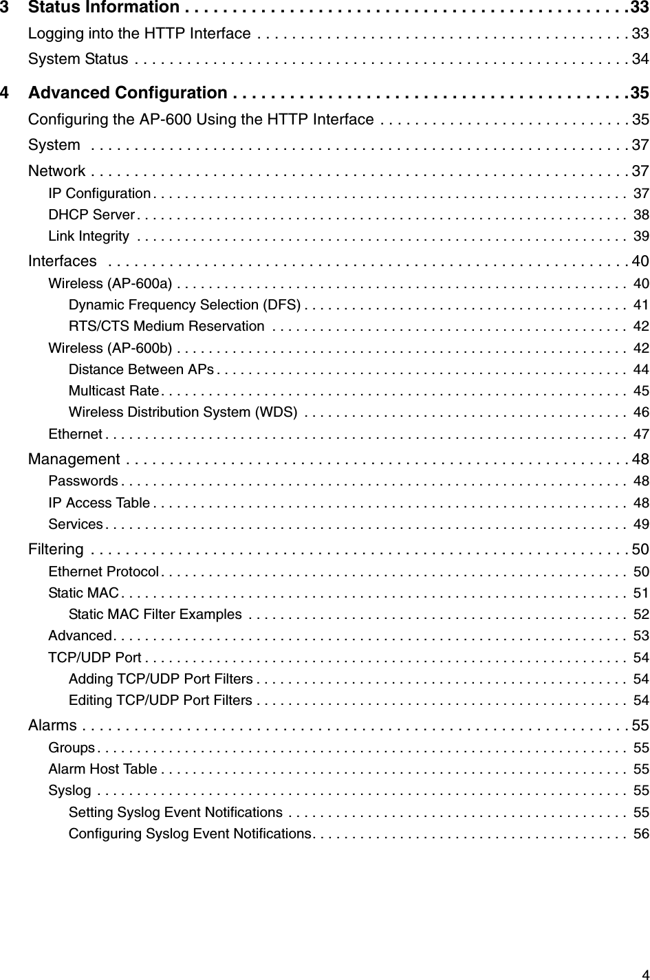
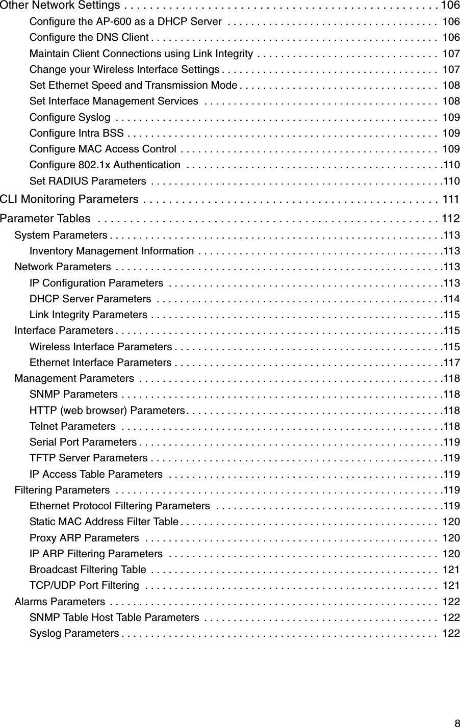
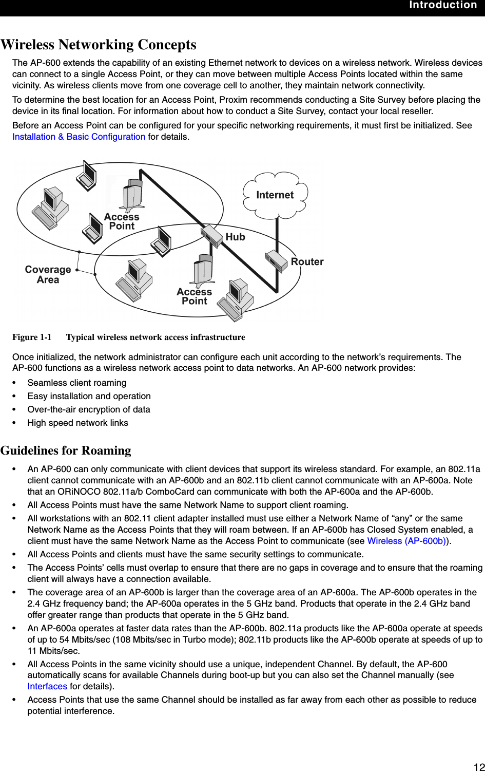
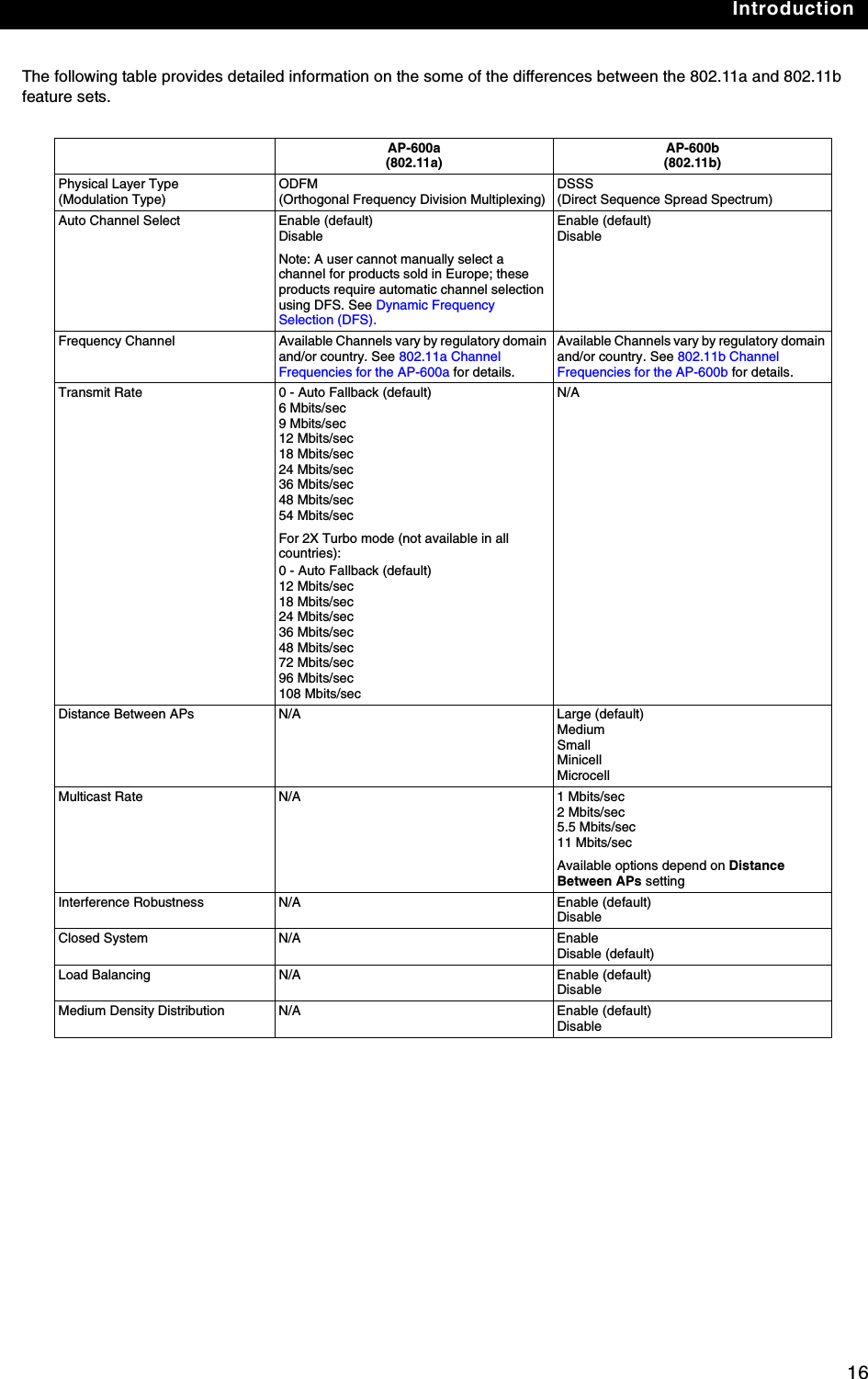
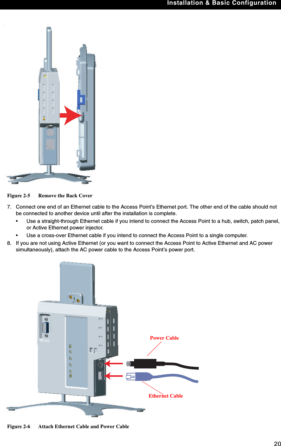
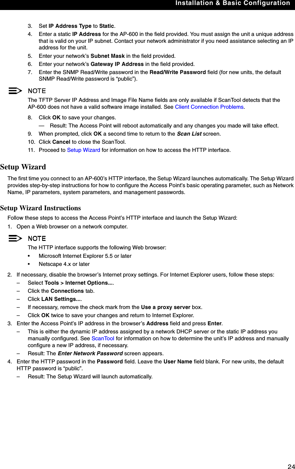
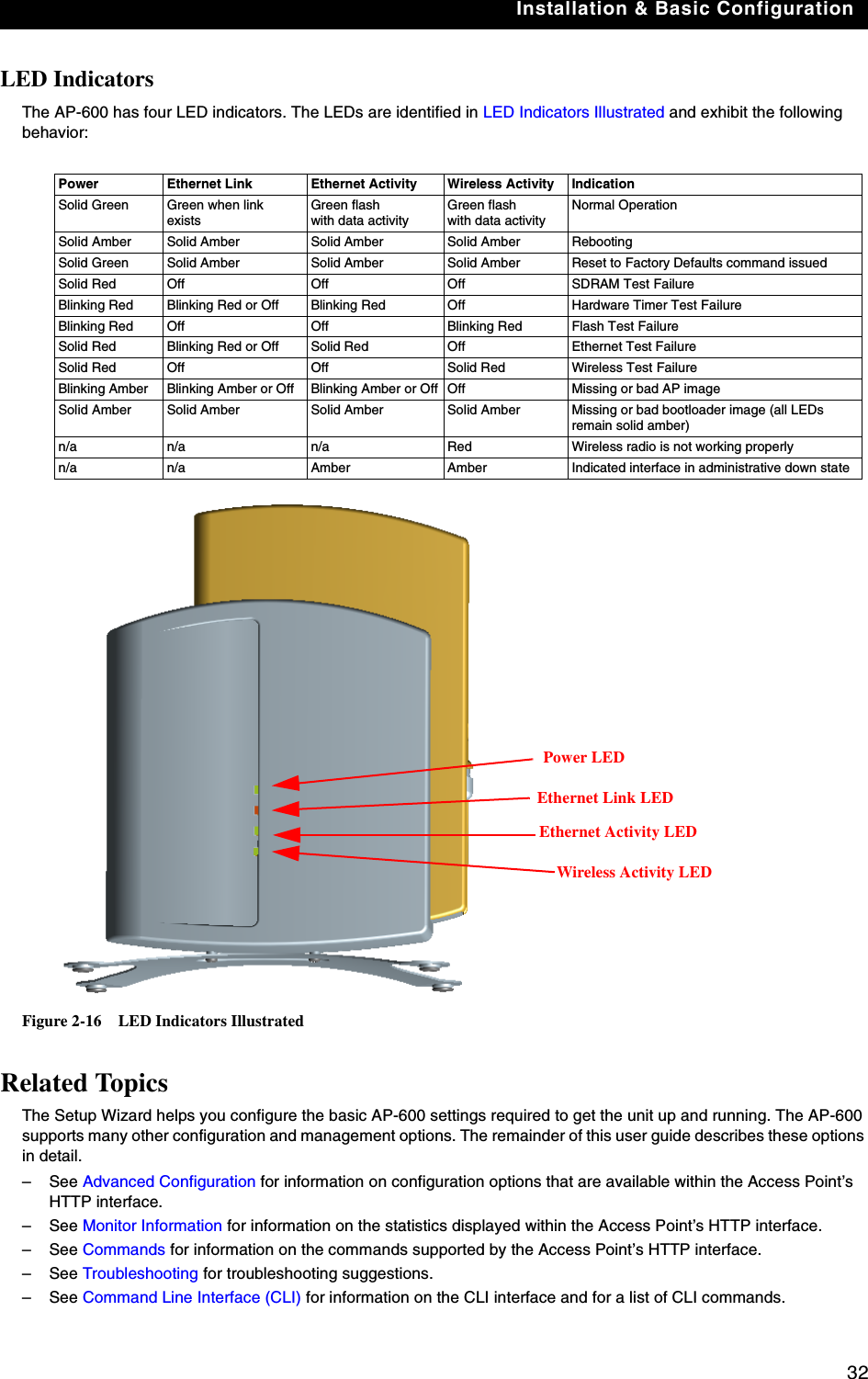

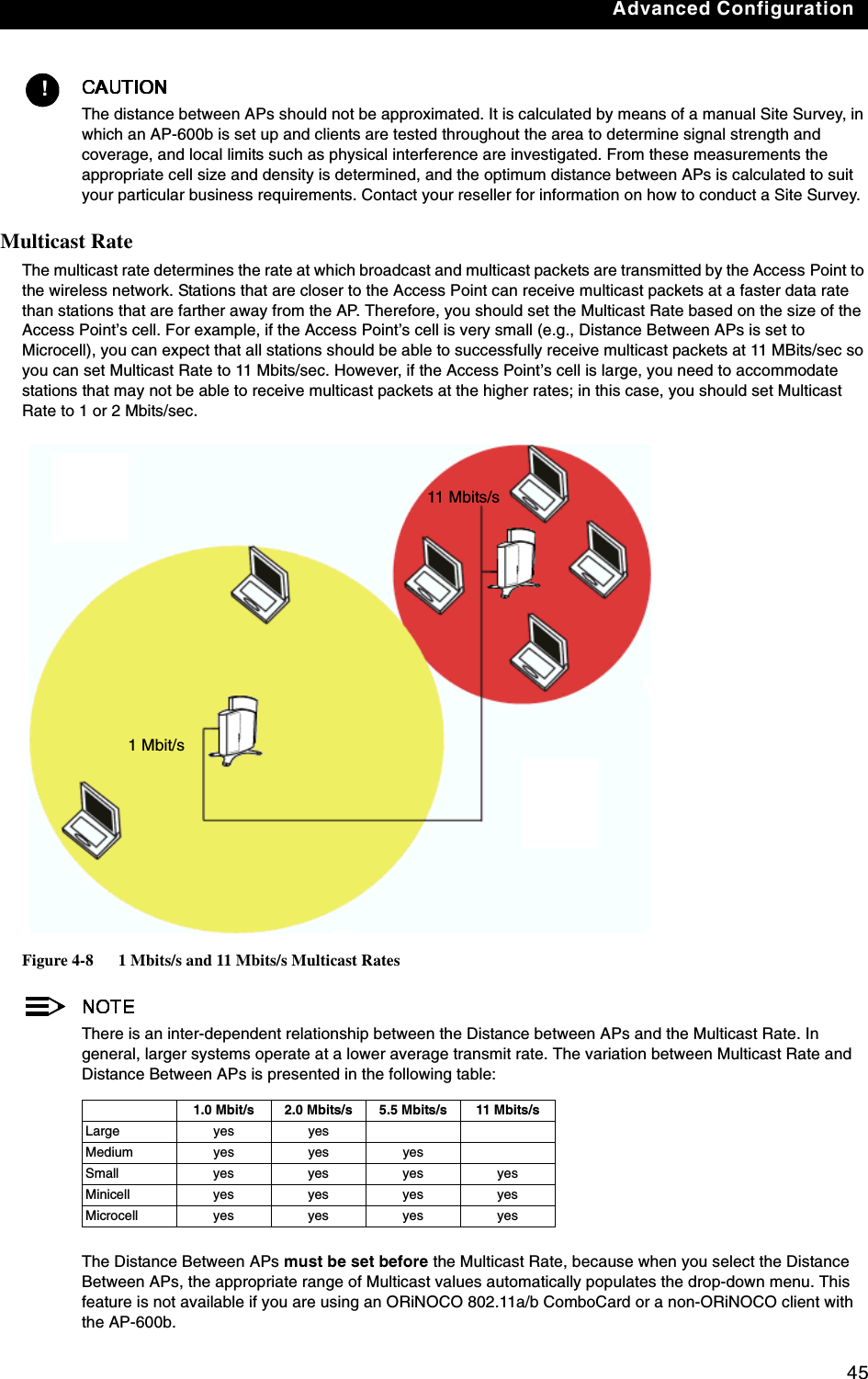
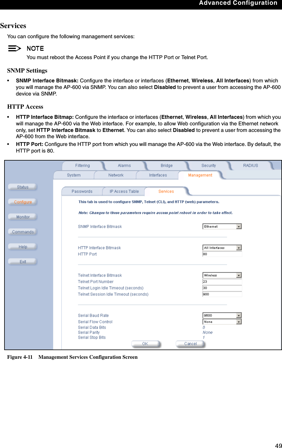
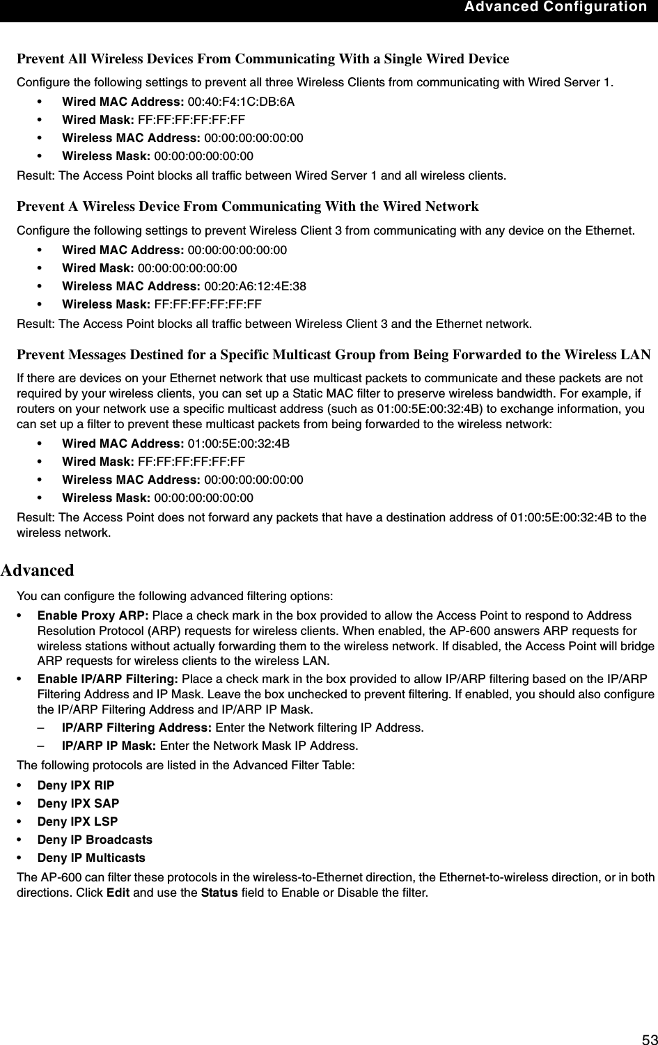
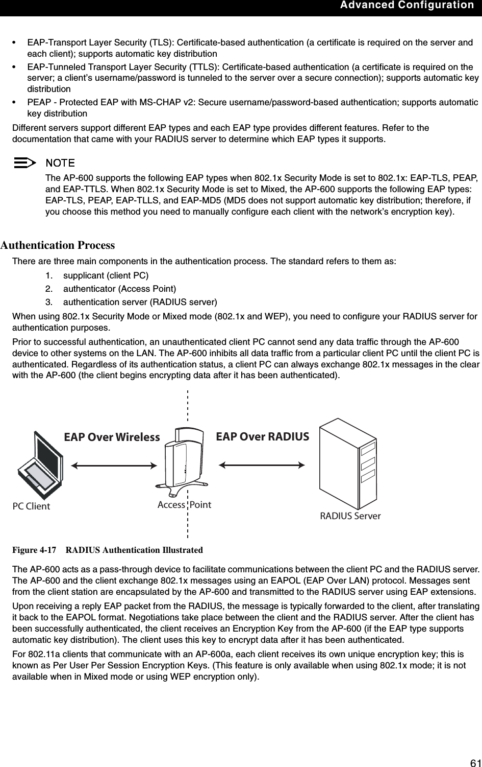
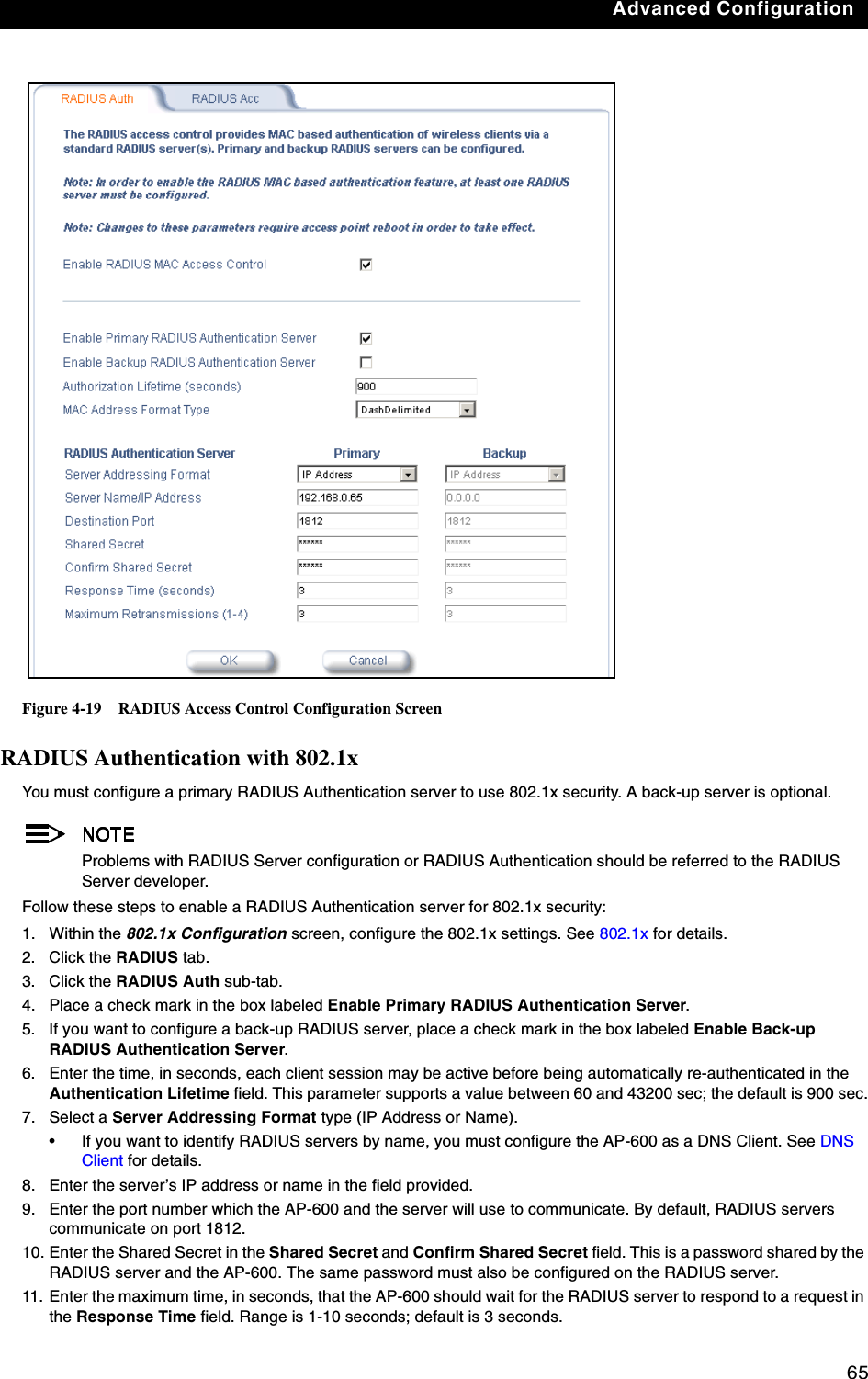


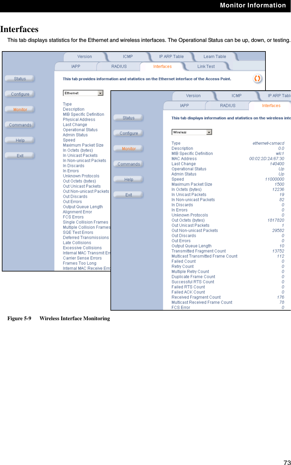


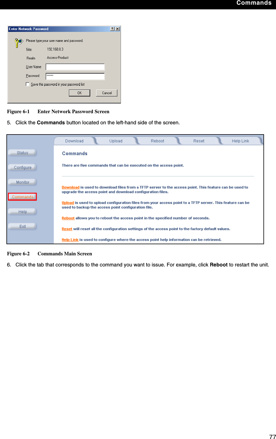
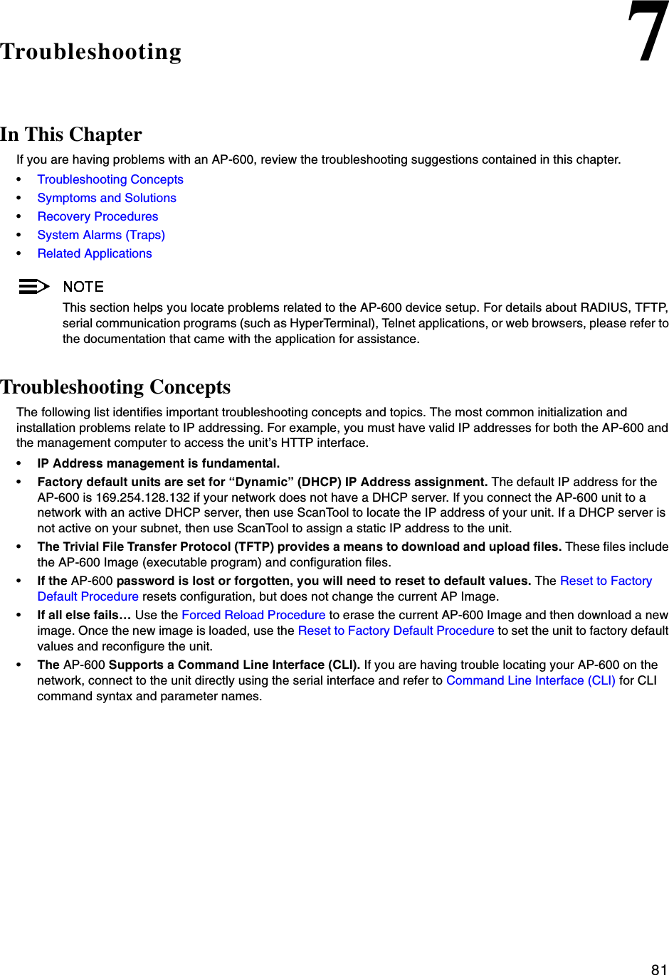
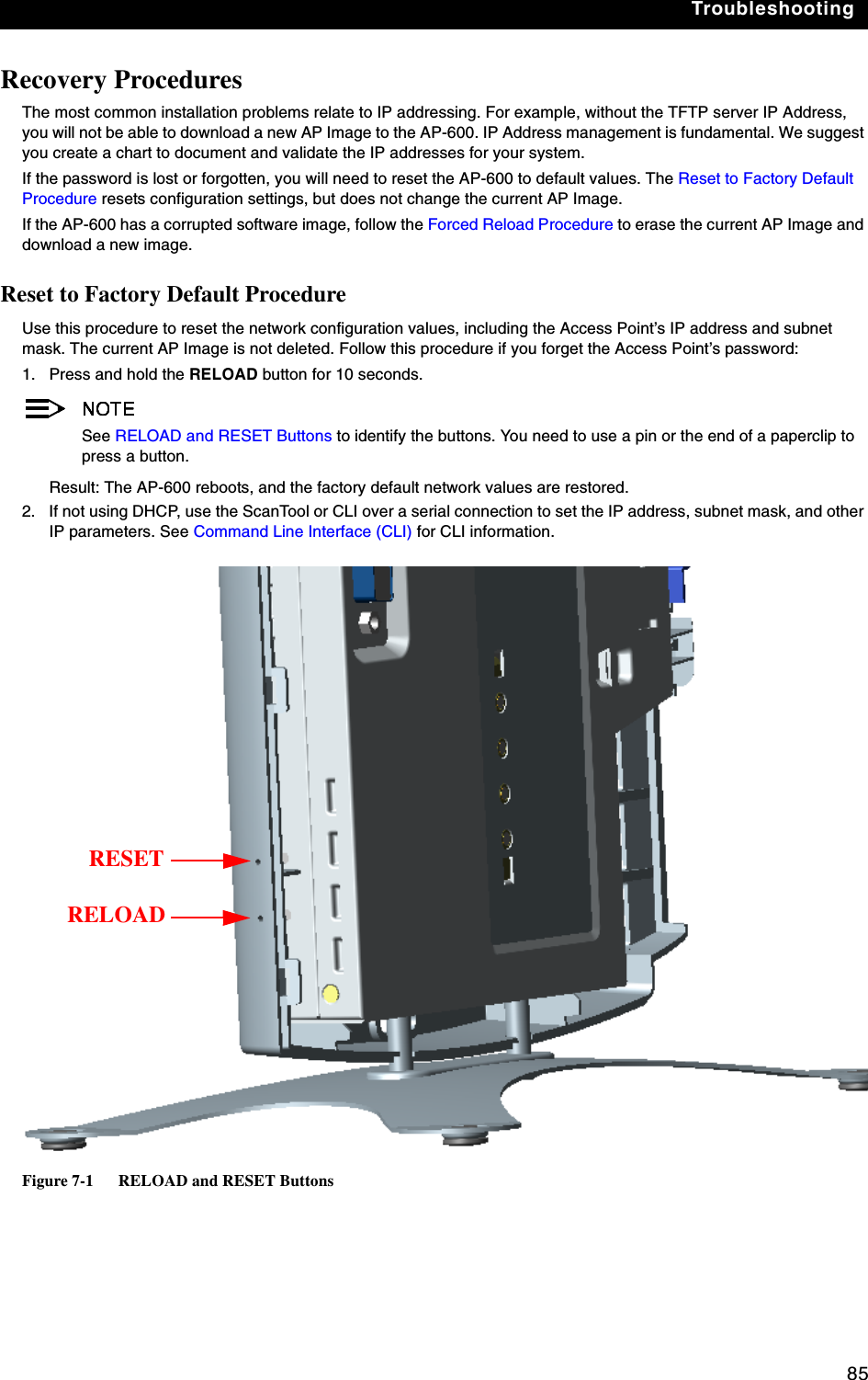
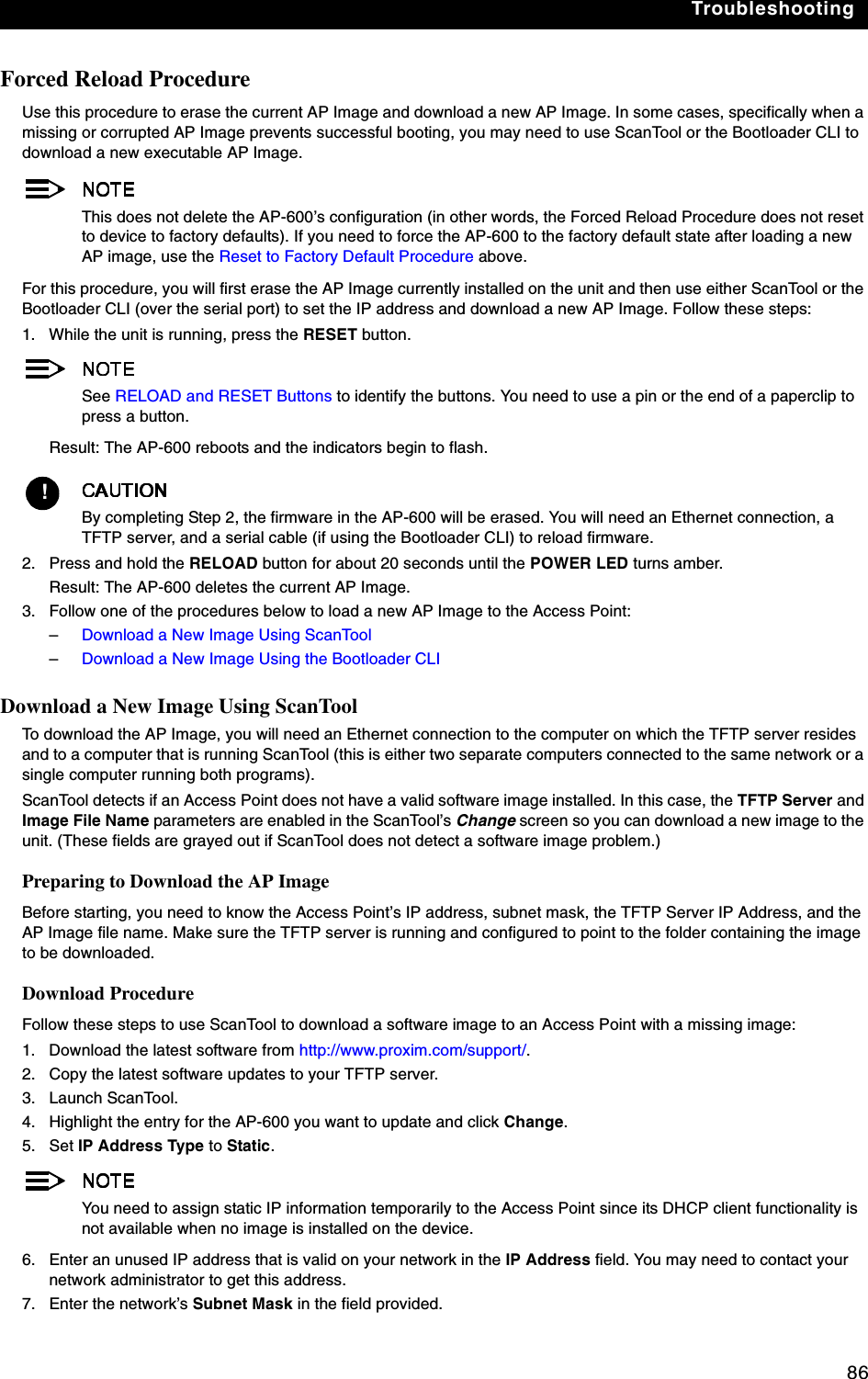
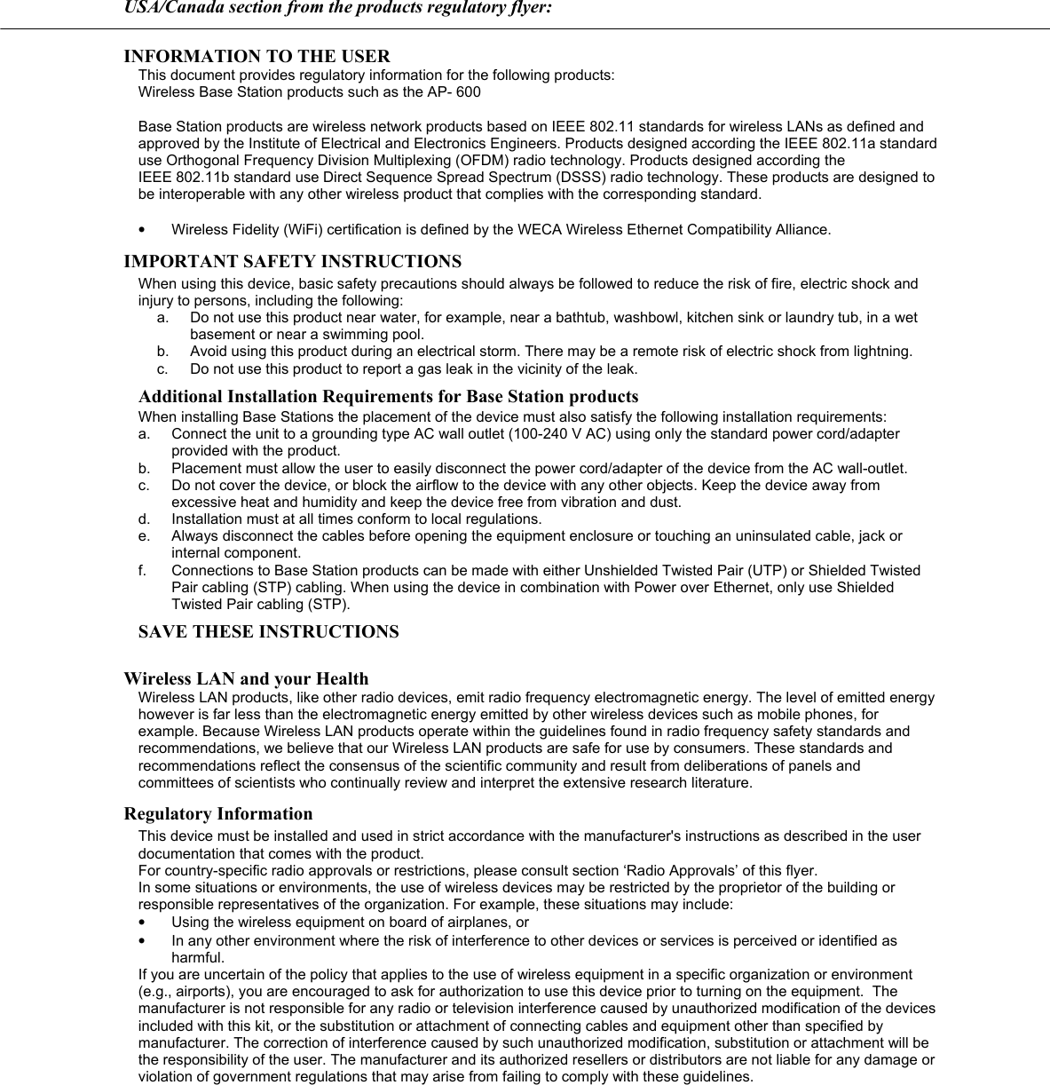
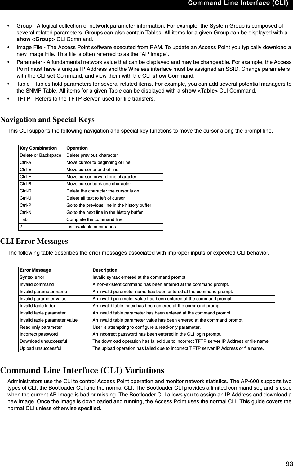
![Troubleshooting878. Enter the network’s Gateway IP Address, if necessary. You may need to contact your network administrator to get this address. You should only need to enter the default gateway address if the Access Point and the TFTP server are separated by a router.9. Enter the IP address of your TFTP server in the field provided.10. Enter the Image File Name (including the file extension). Enter the full directory path and file name. If the file is located in the default TFTP directory, you need enter only the file name.11. Click OK.–Result: The Access Point will reboot and the download will begin automatically. You should see downloading activity begin after a few seconds within the TFTP server’s status screen.12. Click OK when prompted that the device has been updated successfully to return to the Scan List screen.13. Click Cancel to close the ScanTool.14. When the download process is complete, configure the AP-600 as described in Installation & Basic Configuration and Advanced Configuration. Download a New Image Using the Bootloader CLITo download the AP Image, you will need an Ethernet connection to the computer on which the TFTP server resides. This can be any computer on the LAN or connected to the AP-600 with a cross-over Ethernet cable.You must also connect the AP-600 to a computer with a standard serial cable and use a terminal client, such as HyperTerminal. From the terminal, enter CLI Commands to set the IP address and download an AP Image.Preparing to Download the AP ImageBefore starting, you need to know the Access Point’s IP address, subnet mask, the TFTP Server IP Address, and the AP Image file name. Make sure the TFTP server is running and configured to point to the folder containing the image to be downloaded.Download Procedure1. Download the latest software from http://www.proxim.com/support/. 2. Copy the latest software updates to your TFTP server’s default directory.3. Use a straight-through serial cable to connect the Access Point’s serial port to your computer’s serial port.You must remove the Access Point’s cable cover and front cover to access the serial port.4. Open your terminal emulation program (like HyperTerminal) and set the following connection properties:•Com Port: <COM1, COM2, etc., depending on your computer>•Baud rate: 9600•Data Bits: 8•Stop bits: 1•Flow Control: None•Parity: None5. Under File -> Properties -> Settings -> ASCII Setup, enable the Send line ends with line feeds option. Result: HyperTerminal sends a line return at the end of each line of code.6. Press the RESET button on the AP-600. Result: The terminal display shows Power On Self Tests (POST) activity. After approximately 30 seconds, a message indicates: Sending Traps to SNMP manager periodically. After this message appears, press the ENTER key repeatedly until the following prompt appears:[Device name]>](https://usermanual.wiki/Proxim-Wireless/A13QBF/User-Guide-301671-Page-92.png)
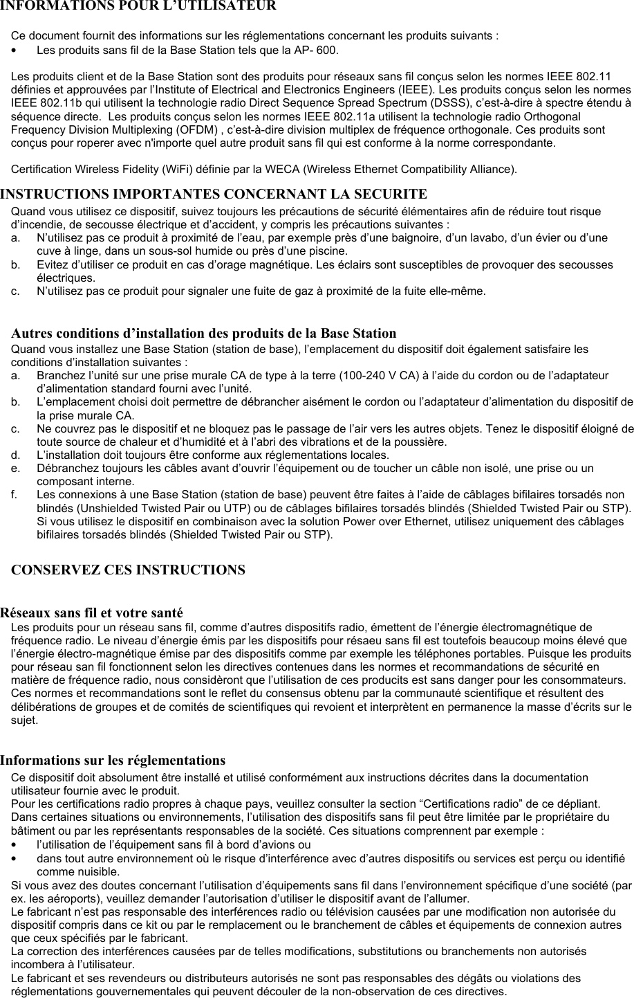
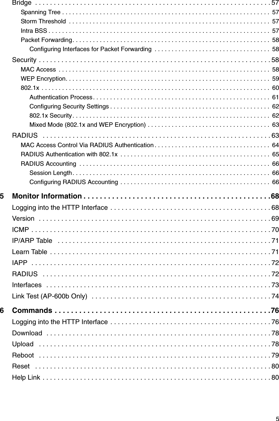
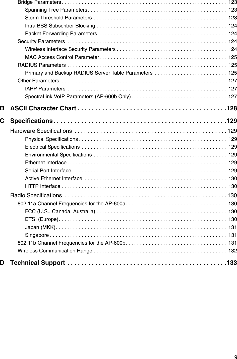
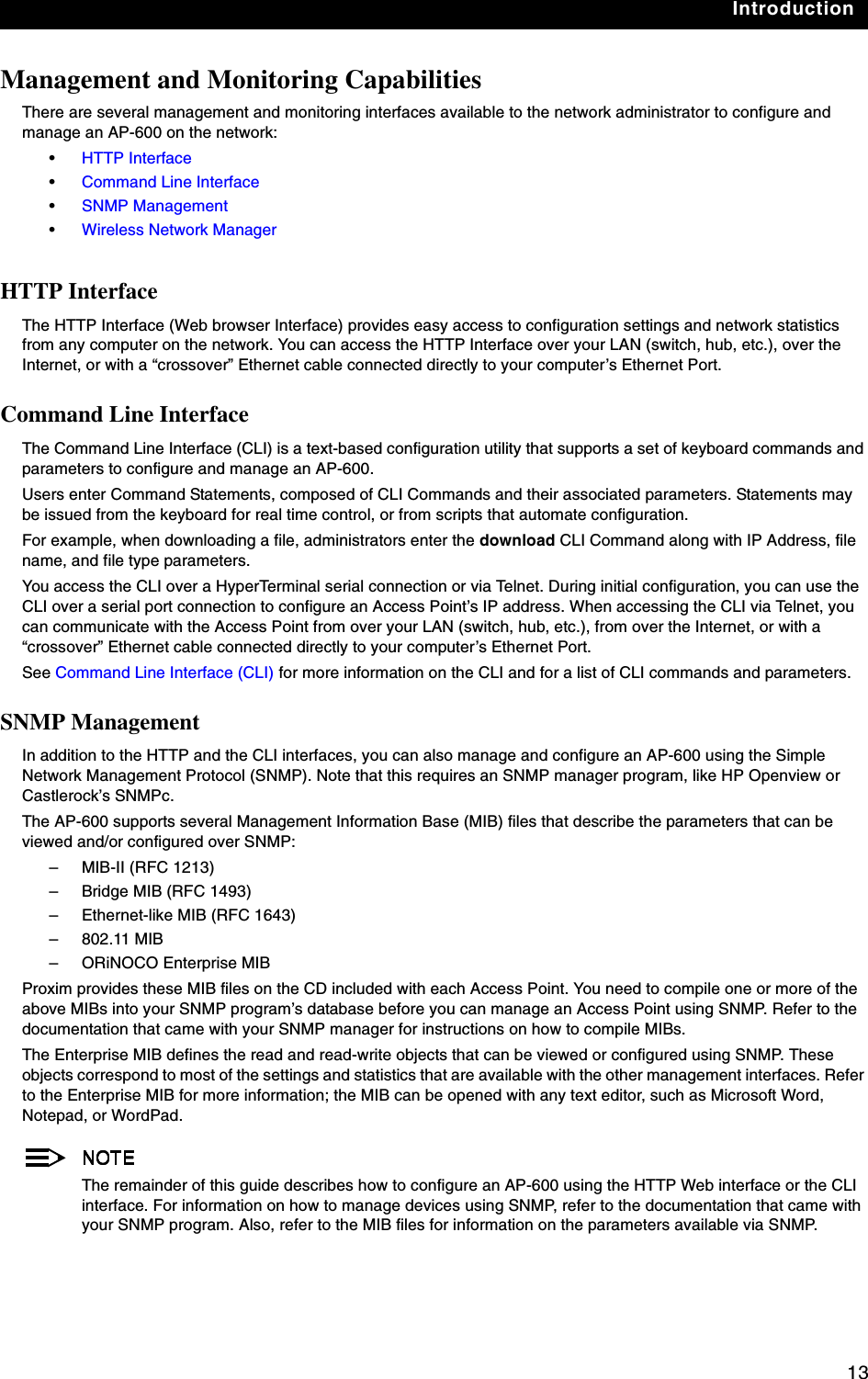
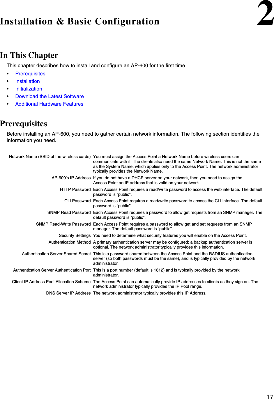
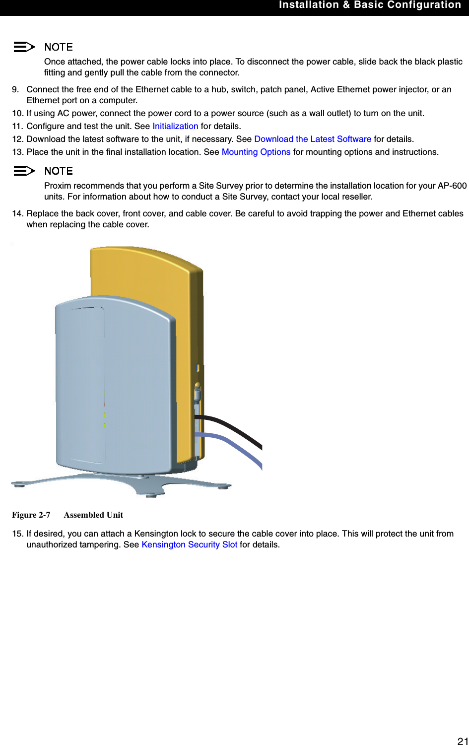
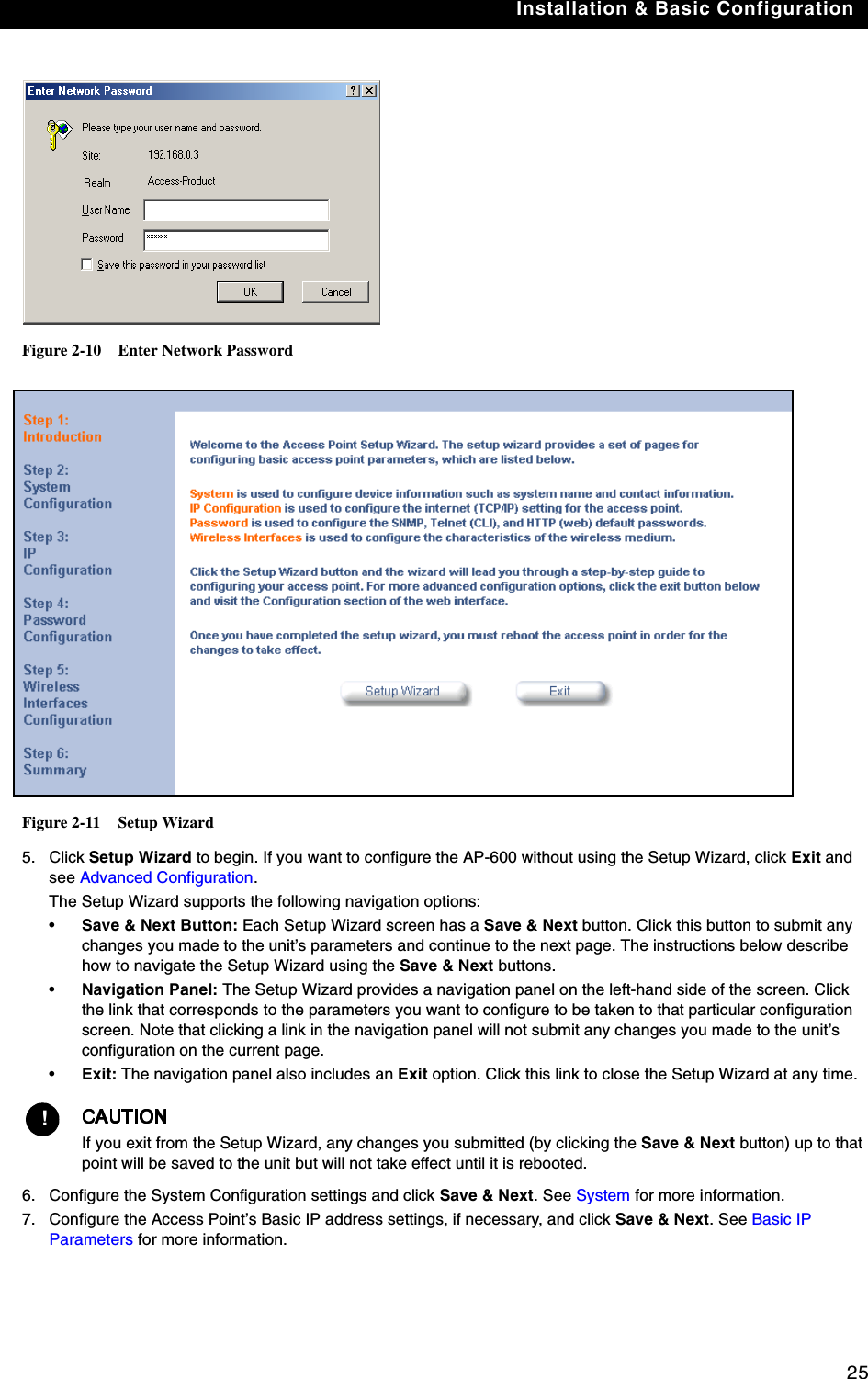
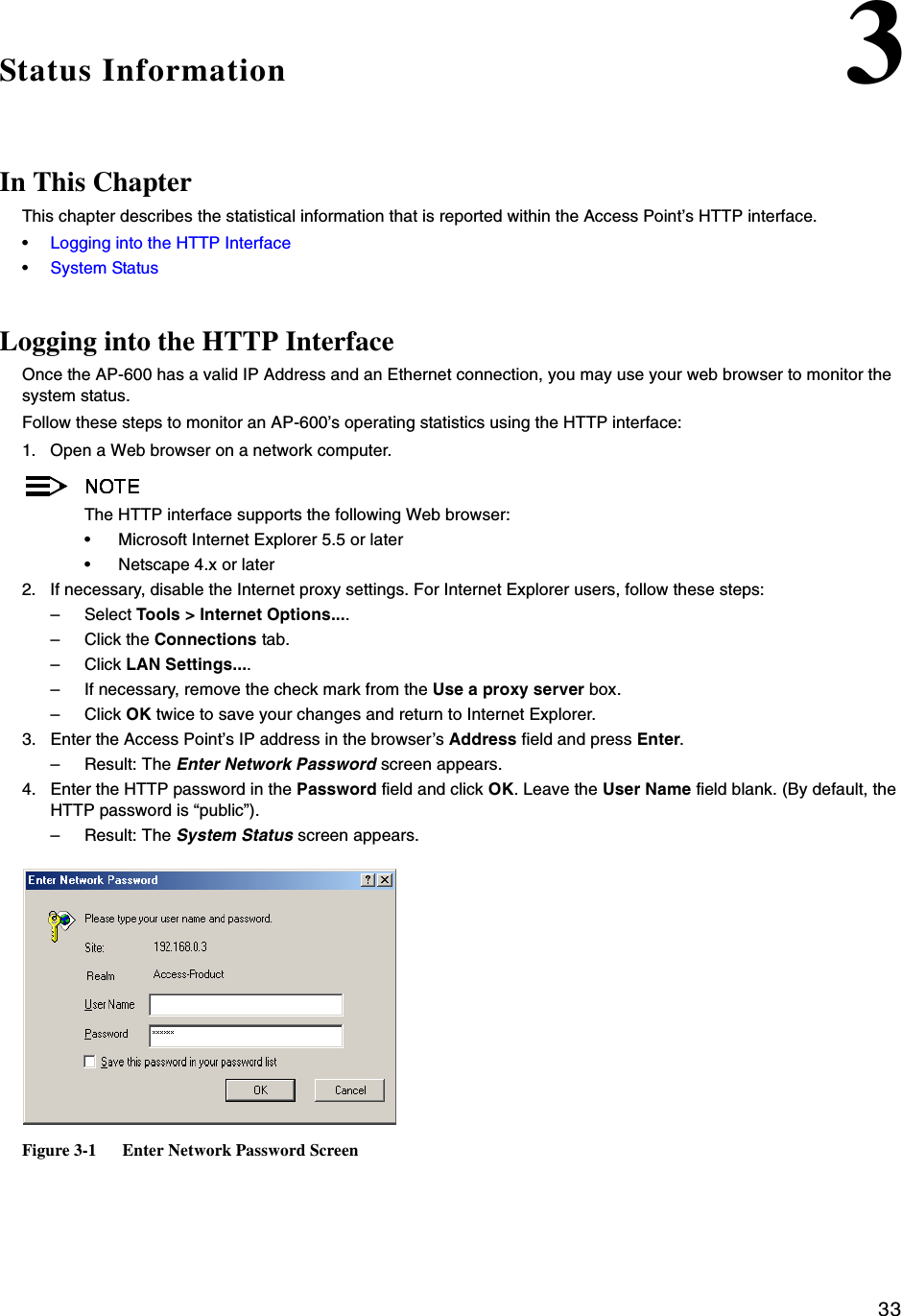
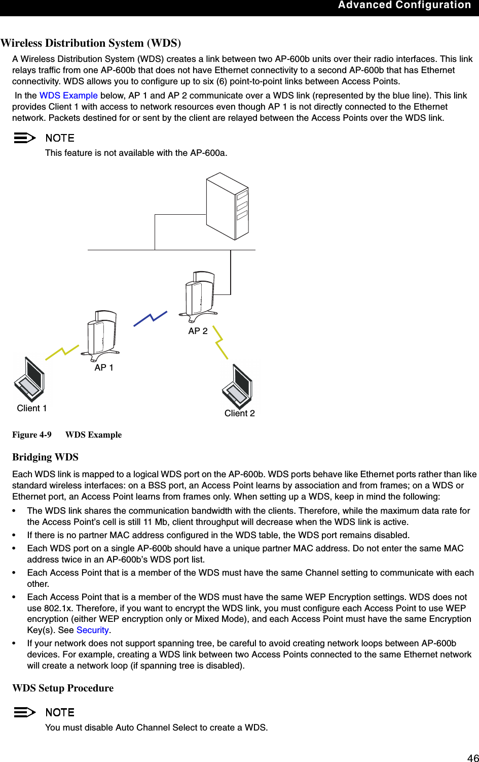
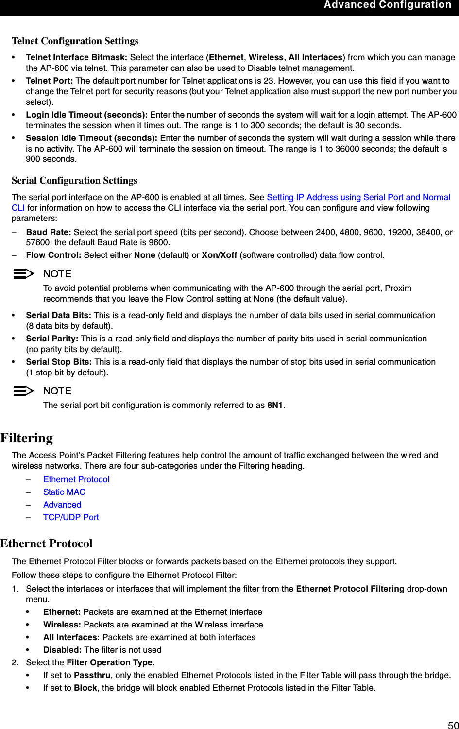
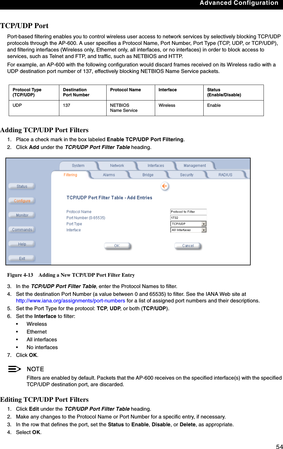
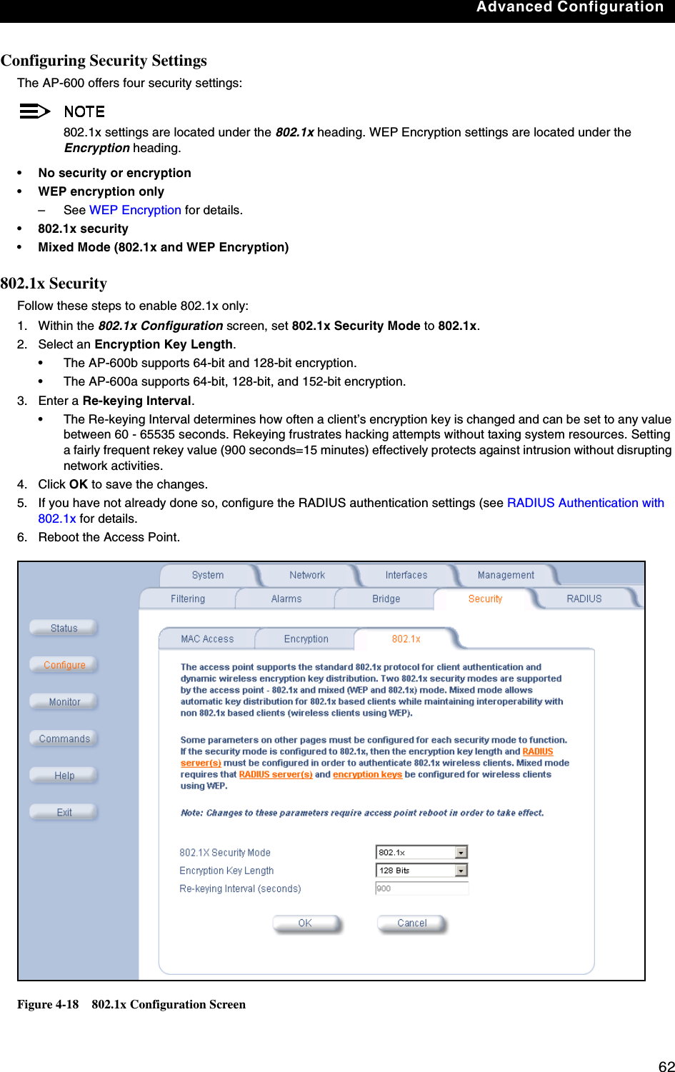
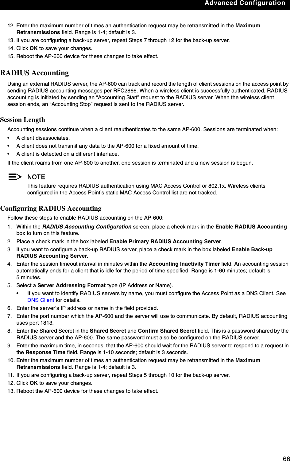
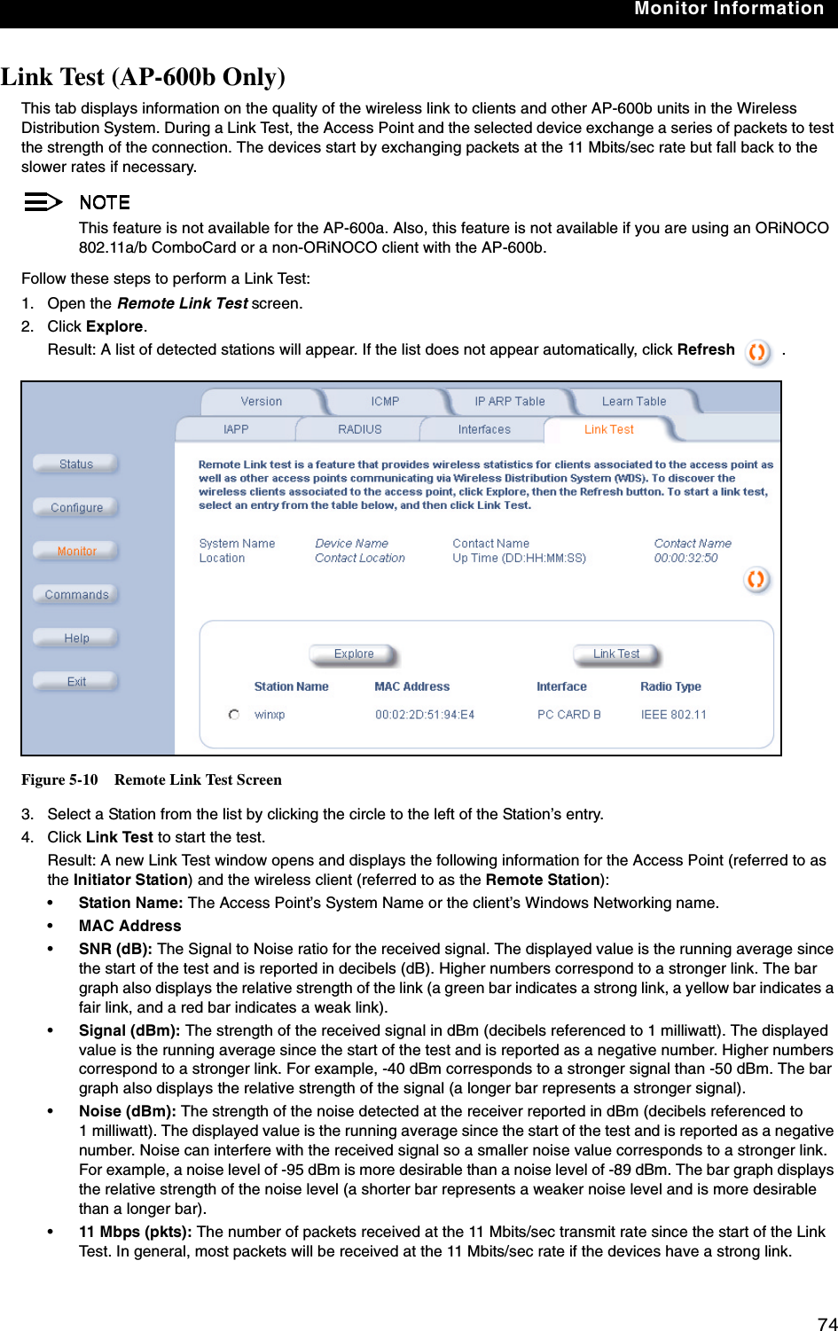
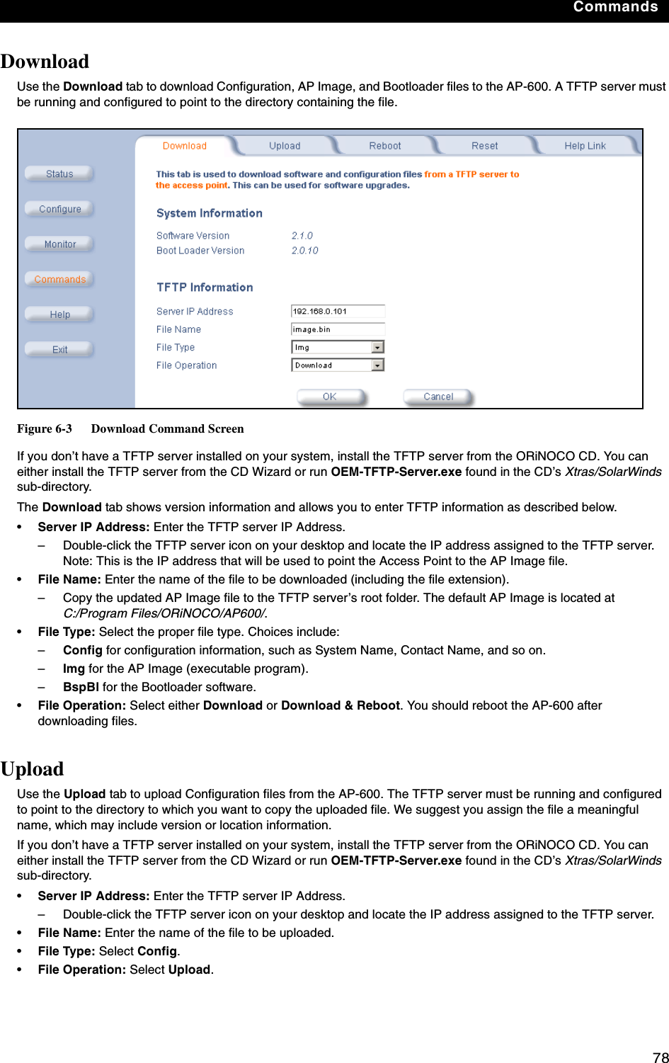
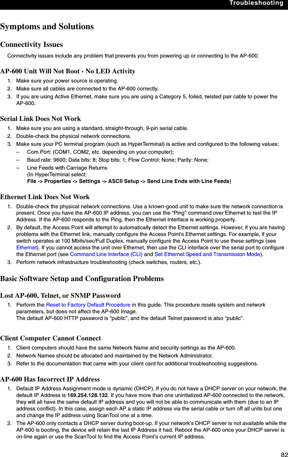
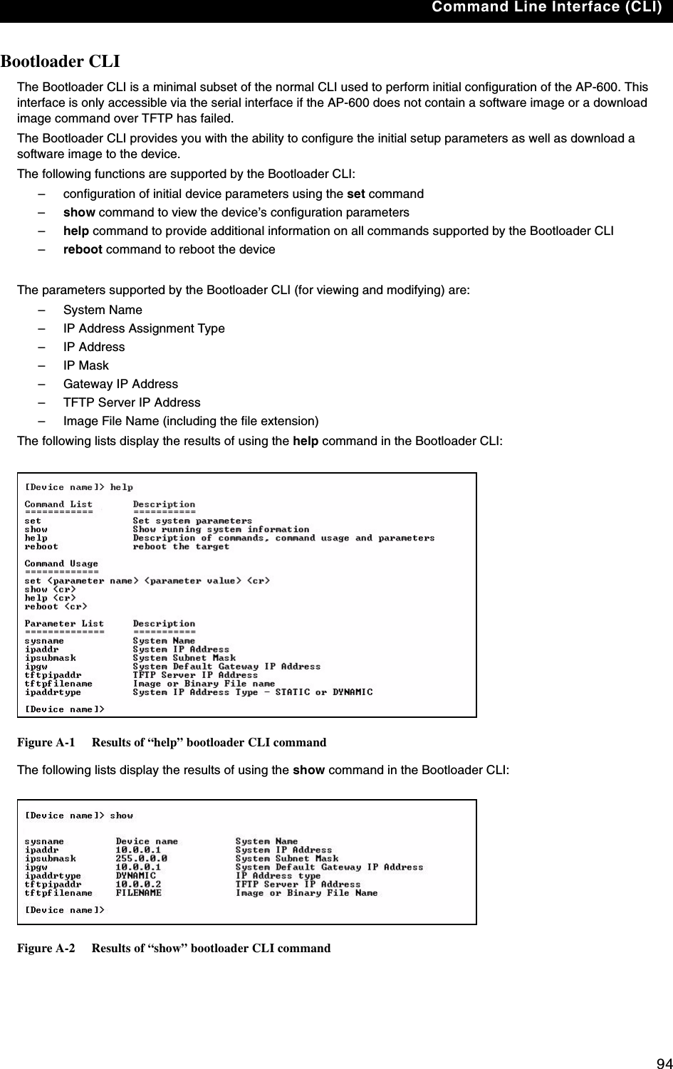
![Troubleshooting887. Enter only the following statements:[Device name]> set ipaddrtype static[Device name]> set ipaddr <Access Point IP Address>[Device name]> set ipsubmask <IP Mask>[Device name]> set tftpipaddr <TFTP Server IP Address>[Device name]> set tftpfilename <AP Image File Name, including file extension>[Device name]> set ipgw <Gateway IP Address>[Device name]> show ip (to confirm your new settings)[Device name]> show tftp (to confirm your new settings)[Device name]> reboot 0Example: [Device name]> set ipaddrtype static[Device name]> set ipaddr 10.0.0.12[Device name]> set ipsubmask 255.255.255.0[Device name]> set tftpipaddr 10.0.0.20[Device name]> set tftpfilename MyImage.bin[Device name]> set ipgw 10.0.0.30[Device name]> show ip[Device name]> show tftp[Device name]> reboot 0Result: The AP-600 will reboot and then download the image file. You should see downloading activity begin after a few seconds within the TFTP server’s status screen.8. When the download process is complete, configure the AP-600 as described in Installation & Basic Configuration and Advanced Configuration. Setting IP Address using Serial Port and Normal CLIUse the following procedure to set an IP address over the serial port using the CLI. The network administrator typically provides the AP-600 IP address.Hardware and Software Requirements•Standard straight-through serial data (RS-232) cable with a one male DB-9 connector and one female DB-9 connector. The AP-600 comes with a female 9-pin serial port.•ASCII Terminal software, such as HyperTerminal.Attaching the Serial Port Cable1. Unlock and remove the cable cover from the AP-600.2. Remove the front cover from the AP-600 to reveal the serial port.3. Connect one end of the serial cable to the AP-600 and the other end to a serial port on your computer.4. Power on the computer and AP-600, if necessary.Initializing the IP Address using CLIAfter installing the serial port cable, you may use the CLI to communicate with the AP-600. CLI supports most generic terminal emulation programs, such as HyperTerminal (which is included with the Windows operating systems). In addition, many web sites offer shareware or commercial terminal programs you can download. Once the IP address has been assigned, you can use the HTTP interface or the CLI over Telnet to complete configuration.Follow these steps to assign the AP-600 an IP address:1. Open your terminal emulation program (like HyperTerminal) and set the following connection properties:•Com Port: <COM1, COM2, etc., depending on your computer>•Baud rate: 9600•Data Bits: 8•Stop bits: 1•Flow Control: None•Parity: None](https://usermanual.wiki/Proxim-Wireless/A13QBF/User-Guide-301671-Page-93.png)
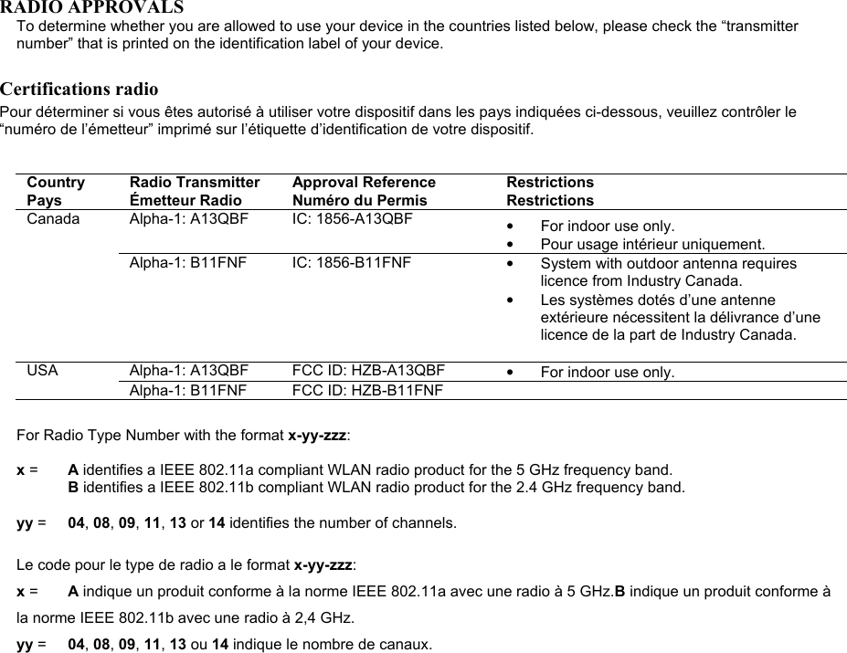
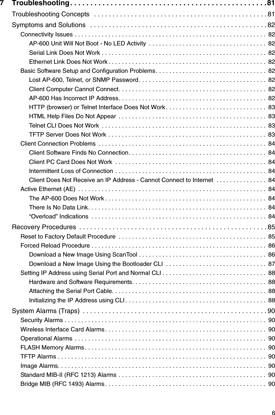
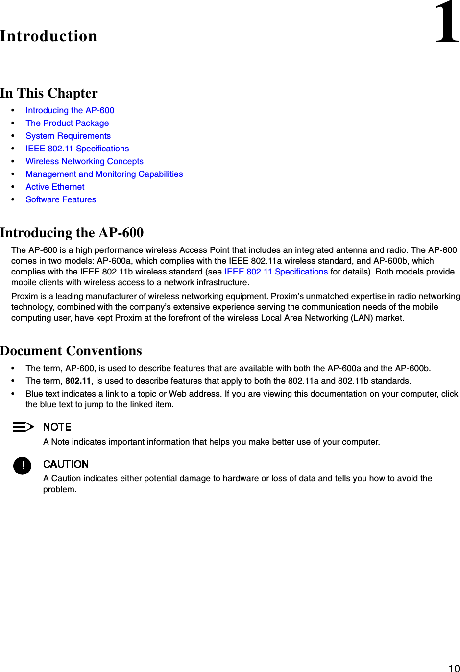
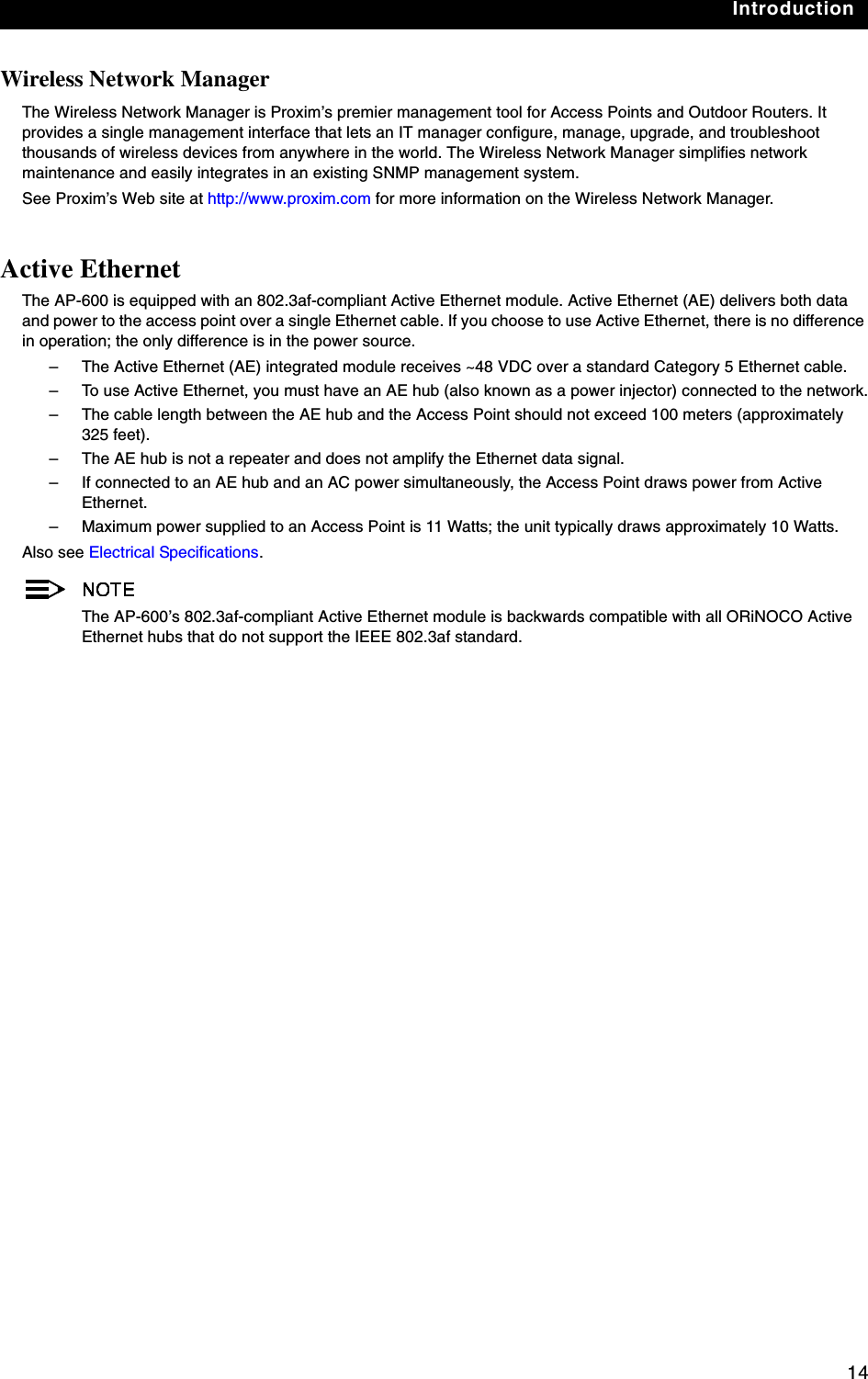
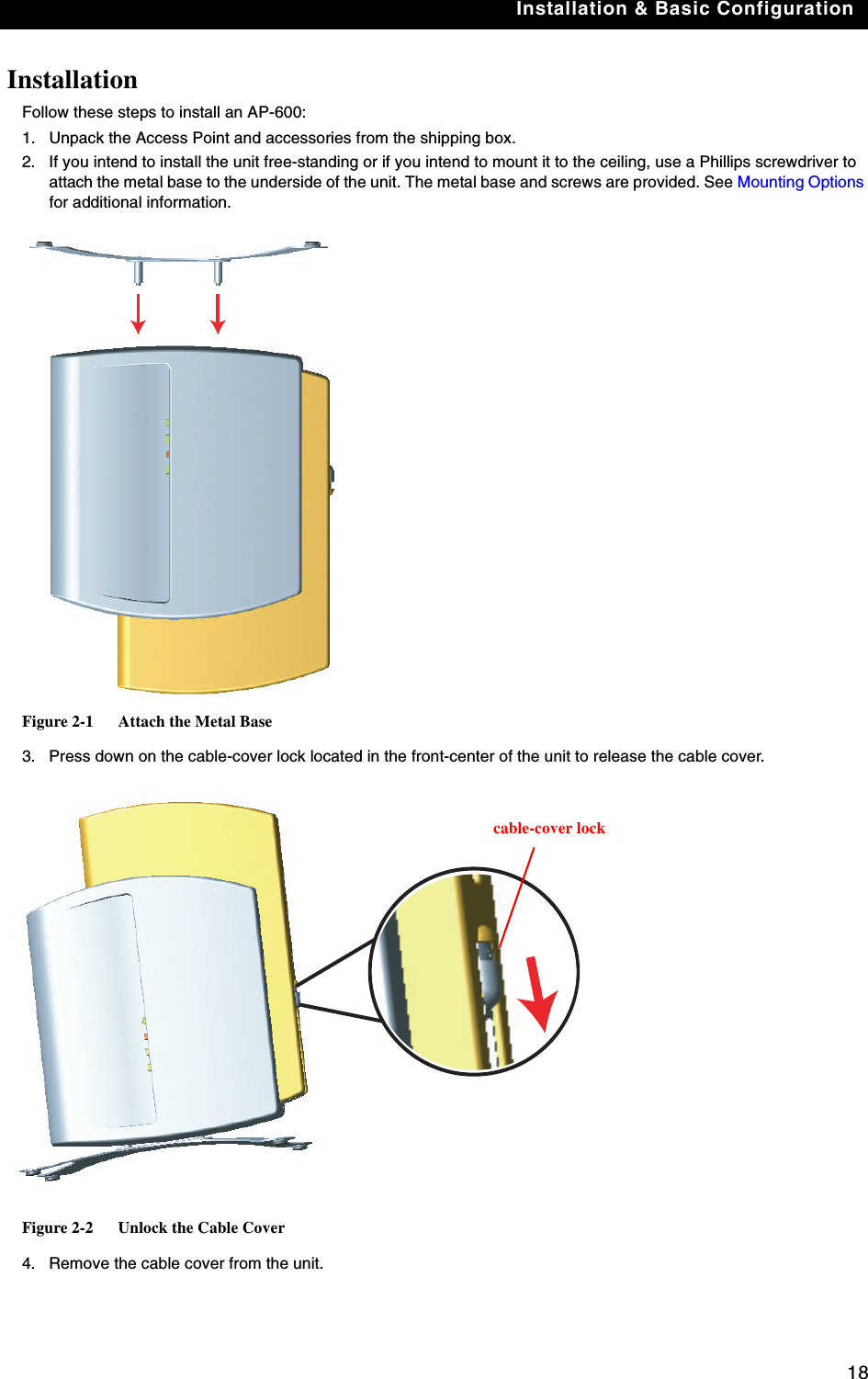
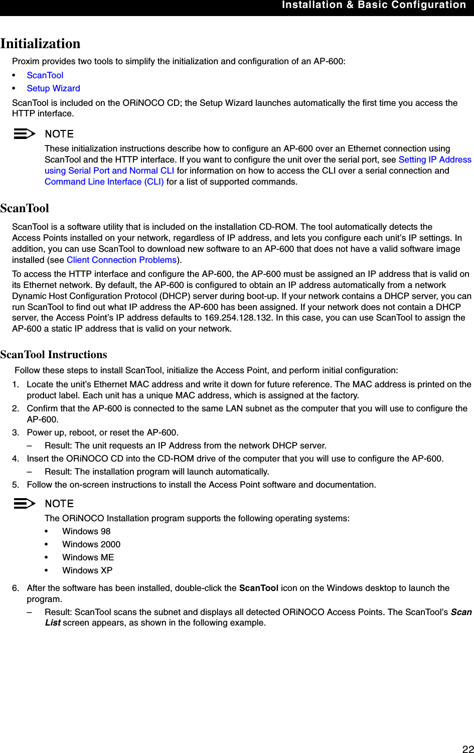
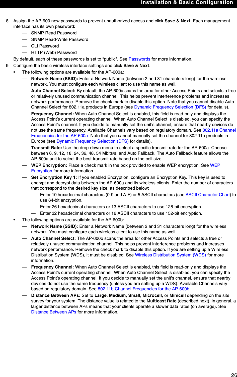
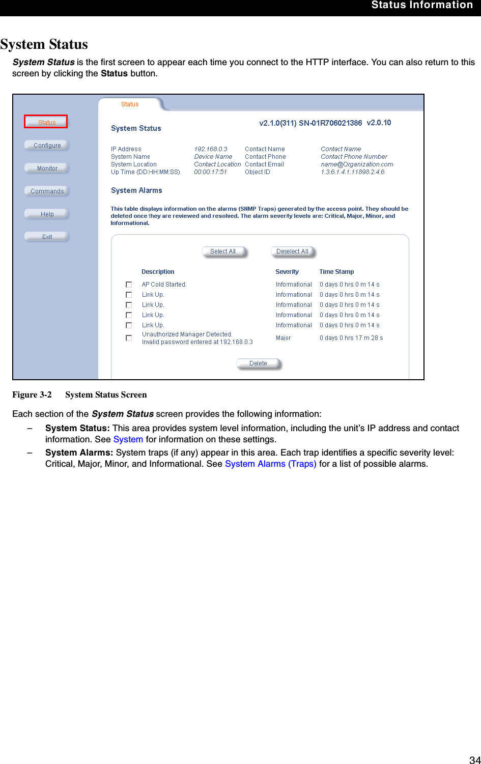
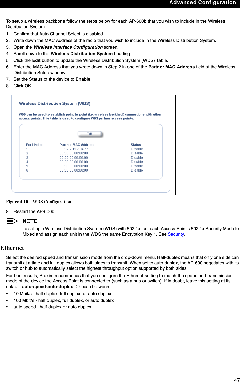
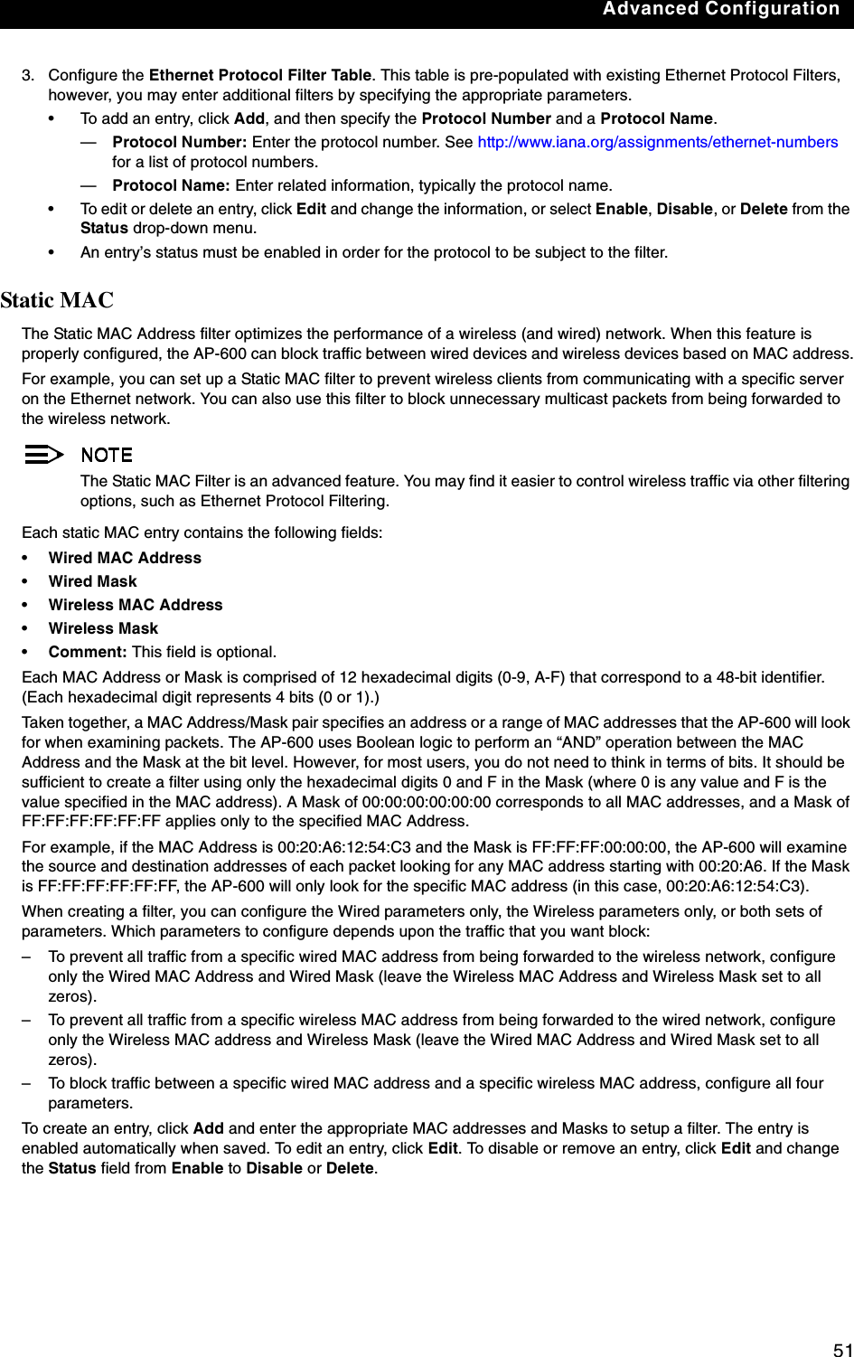
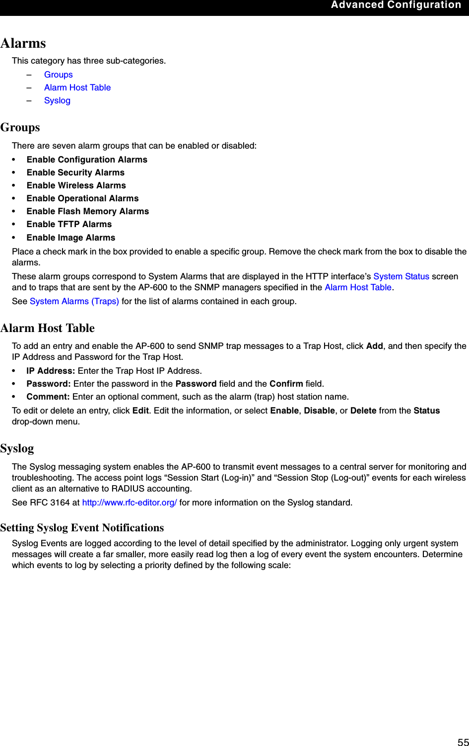
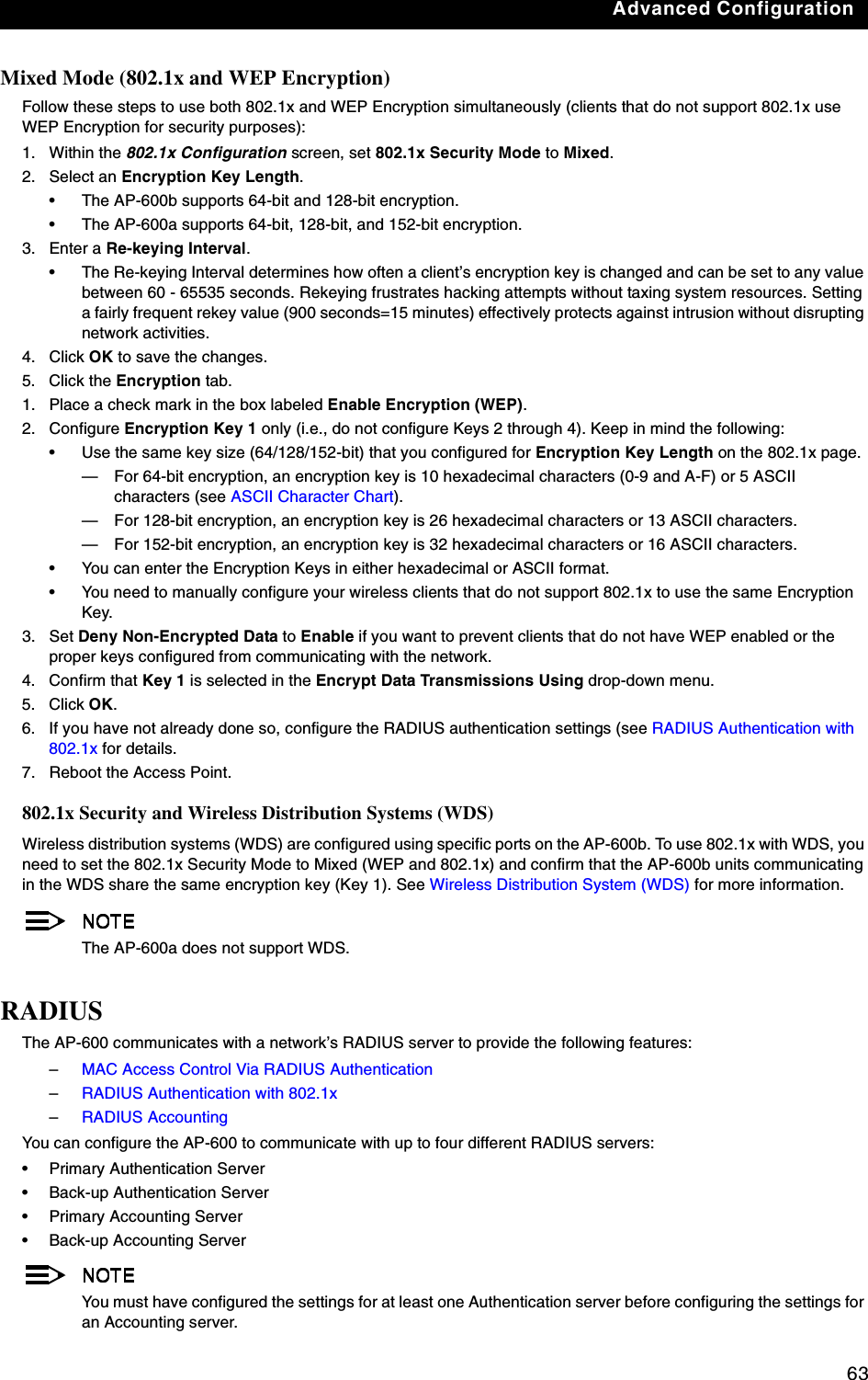
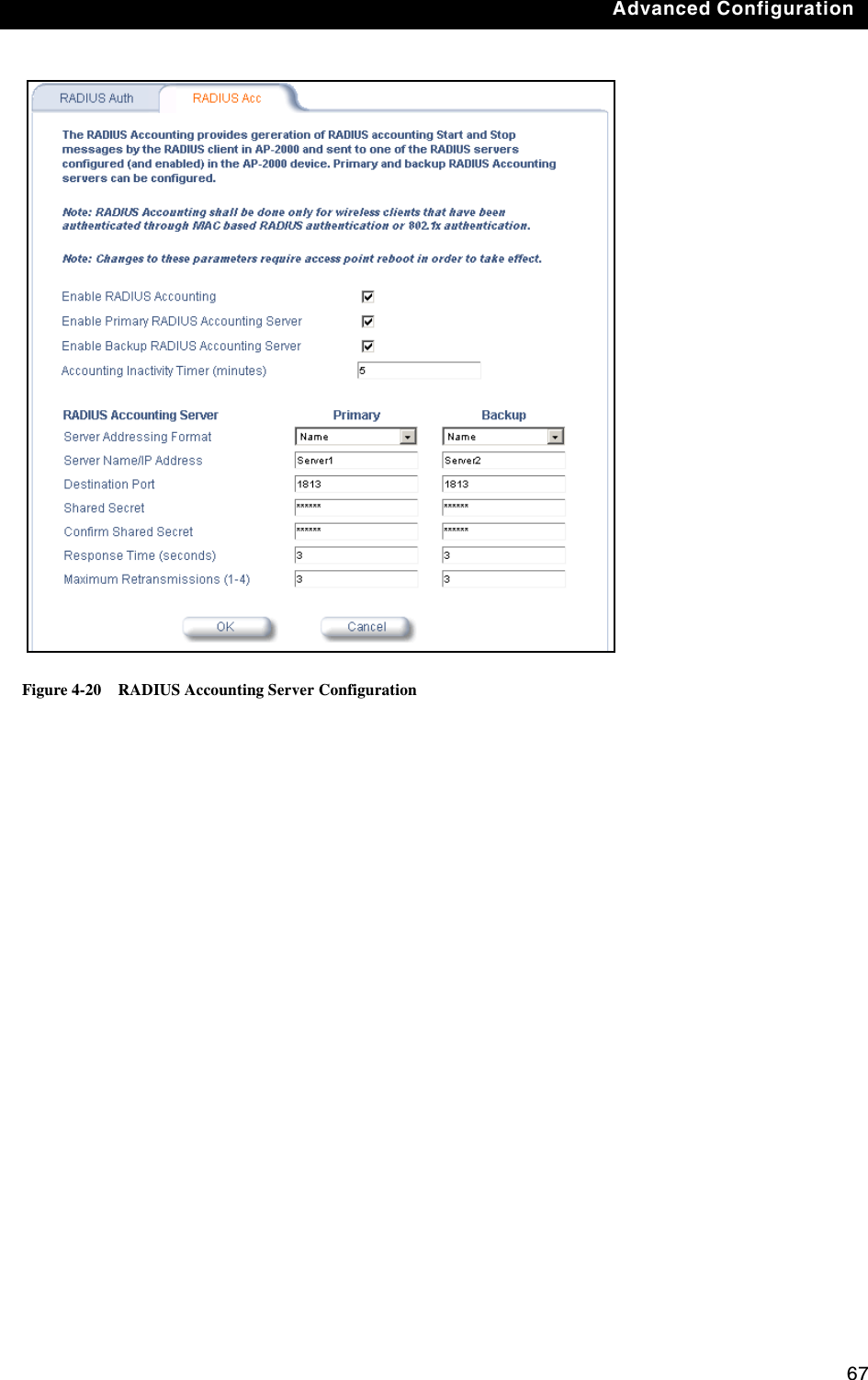
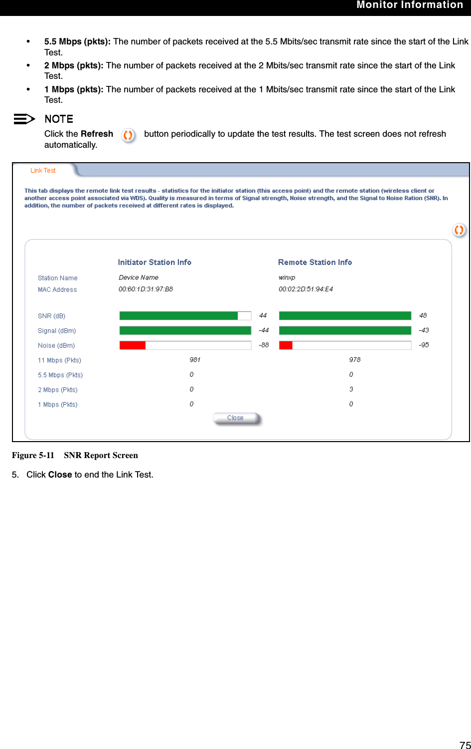
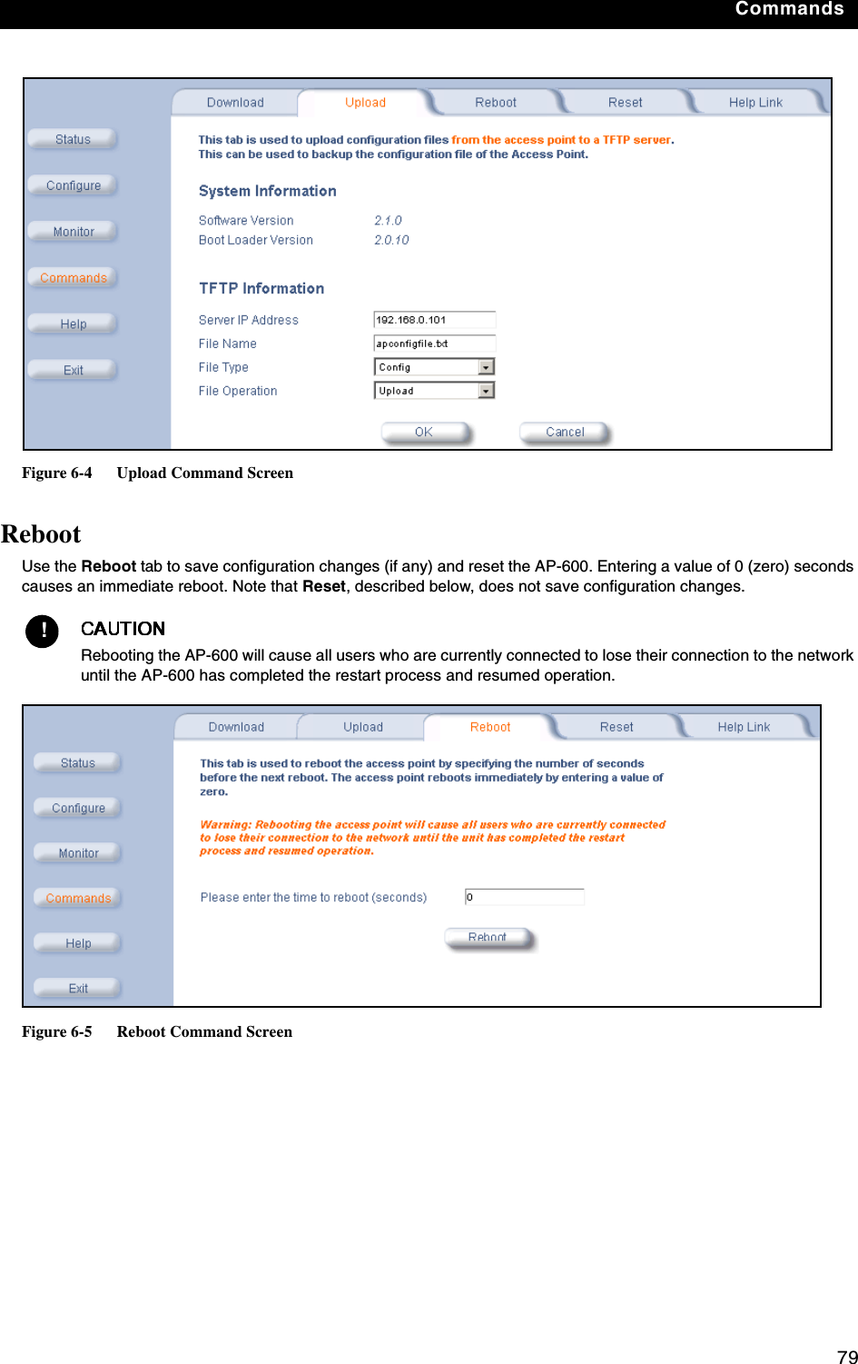
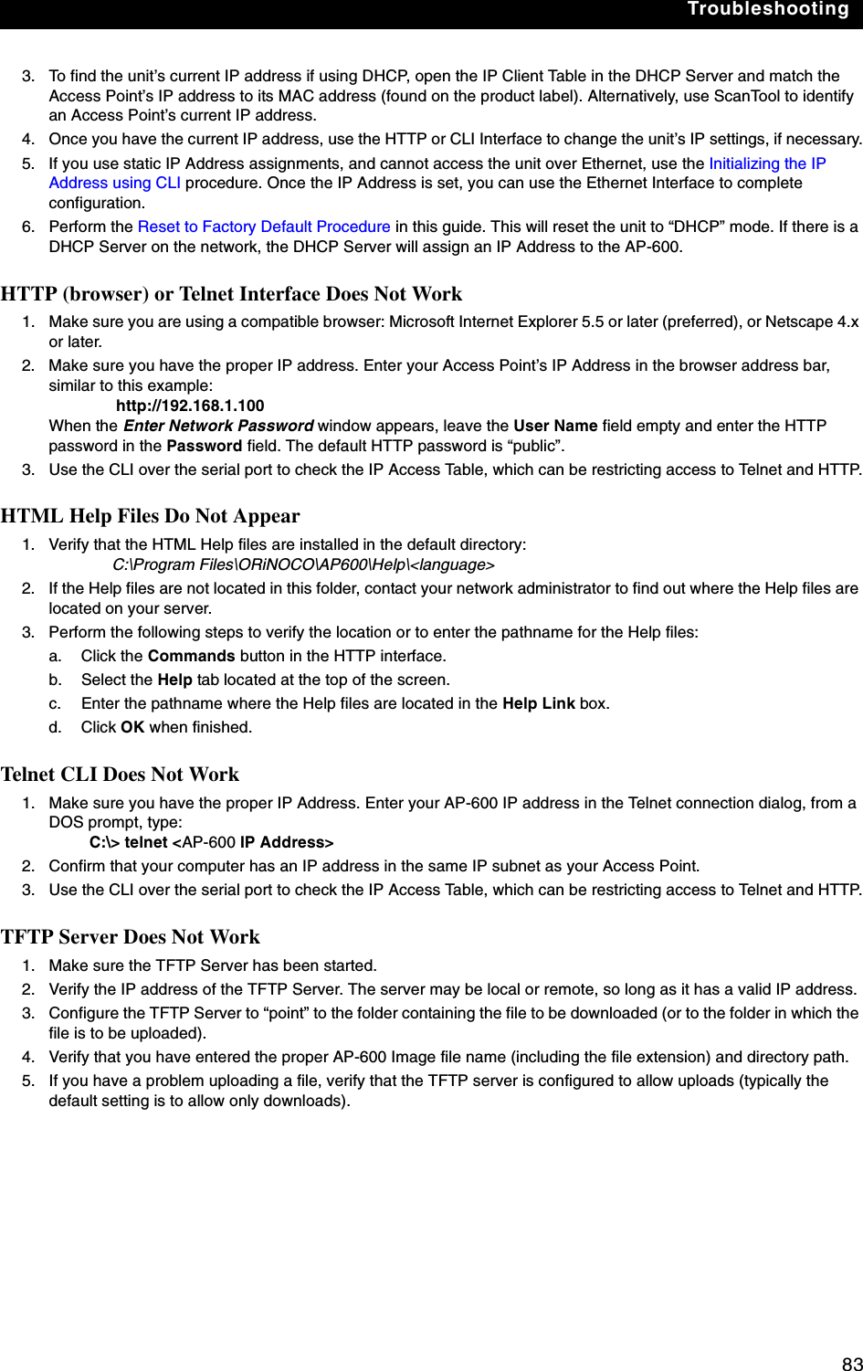
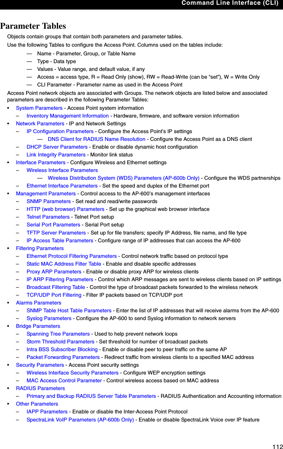
![Troubleshooting892. Under File -> Properties -> Settings -> ASCII Setup, enable the Send line ends with line feeds option. Result: HyperTerminal sends a line return at the end of each line of code.3. Press the RESET button on the AP-600 (see RELOAD and RESET Buttons to identify the location of the RESET button). Result: The terminal display shows Power On Self Tests (POST) activity, and then displays a CLI prompt, similar to the example below. This process may take up to 90 seconds.[Device name]> Please enter password:4. Enter the CLI password (default is public). Result: The terminal displays a welcome message and then the CLI Prompt:[Device name]> 5. Enter show ip. Result: Network parameters appear:Figure 7-2 Result of “show ip” CLI Command6. Change the IP address and other network values using set and reboot CLI commands, similar to the example below (use your own IP address and subnet mask). Note that IP Address Type is set to Dynamic by default. If you have a DHCP server on your network, you should not need to manually configure the Access Point’s IP address; the Access Point will obtain an IP address from the network’s DHCP server during boot-up.Result: After each entry the CLI reminds you to reboot; however wait to reboot until all commands have been entered. [Device name]> set ipaddrtype static[Device name]> set ipaddr <IP Address>[Device name]> set ipsubmask <IP Subnet Mask>[Device name]> set ipgw <Default Gateway IP Address>[Device name]> show ip (to confirm your new settings)[Device name]> reboot 07. After the AP-600 reboots, verify the new IP address by reconnecting to the CLI and enter a show ip command. Alternatively, you can ping the AP-600 from a network computer to confirm that the new IP address has taken effect.8. When the proper IP address is set, use the HTTP interface or CLI over Telnet to configure the rest of the unit’s operating parameters.](https://usermanual.wiki/Proxim-Wireless/A13QBF/User-Guide-301671-Page-94.png)

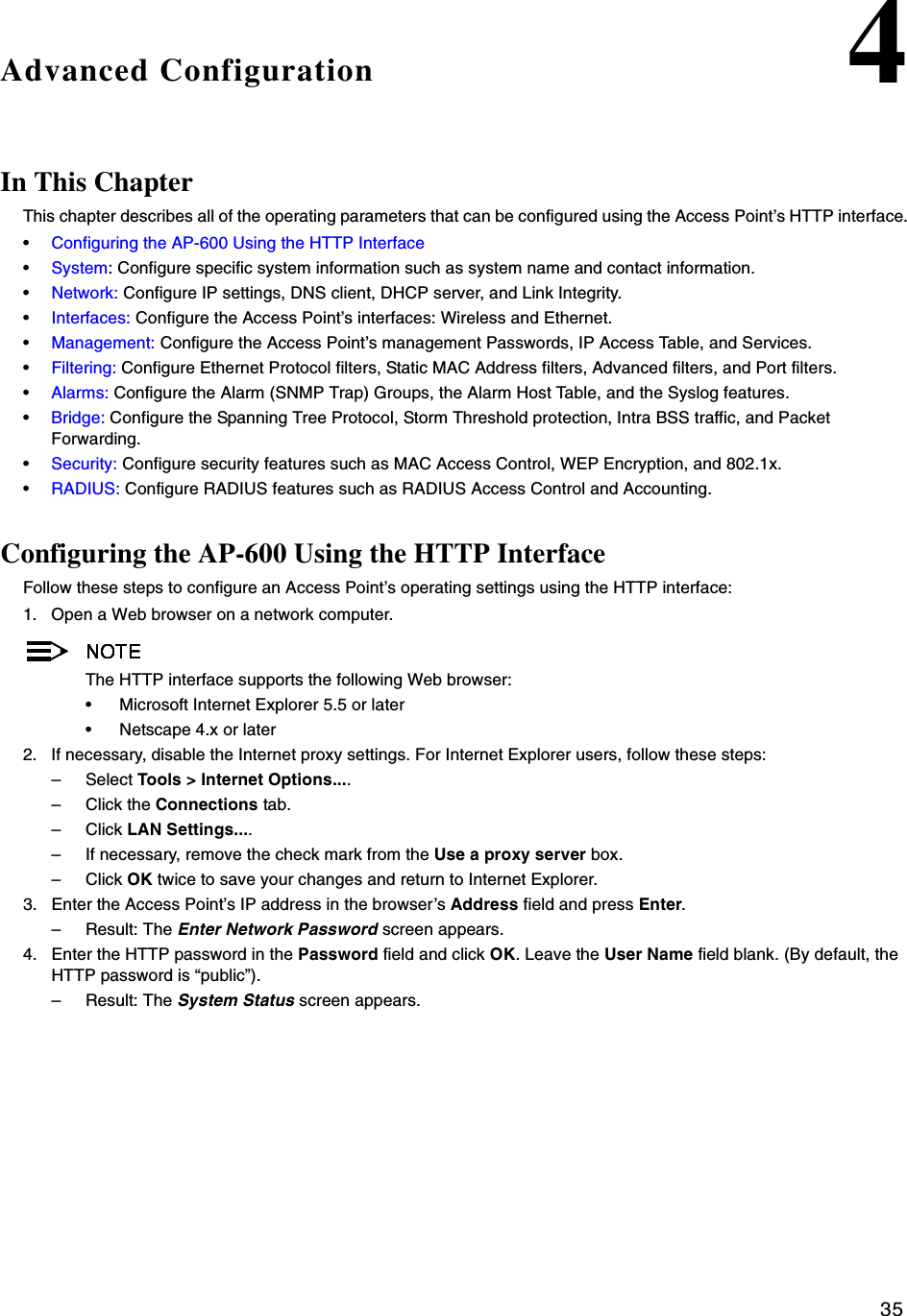
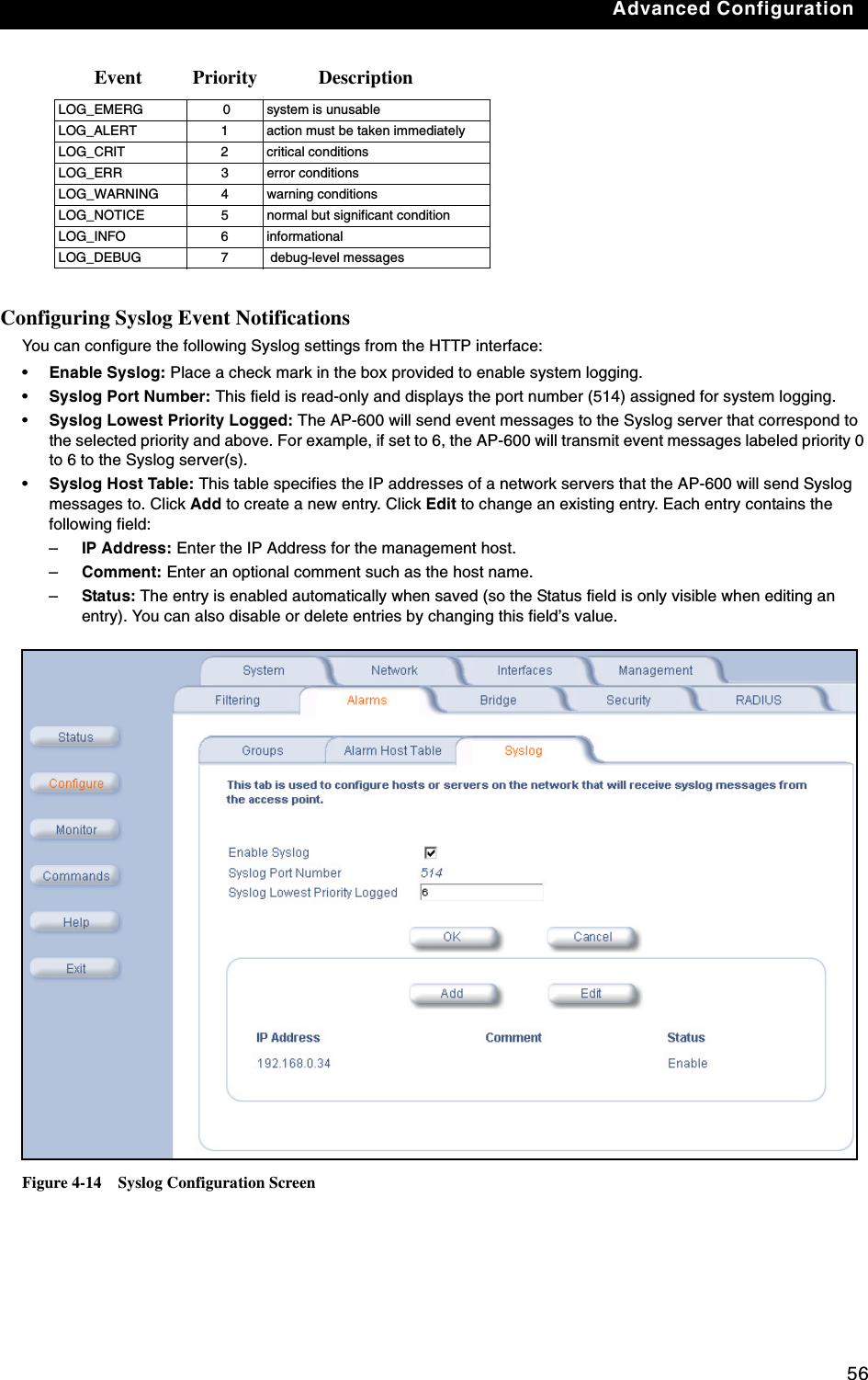
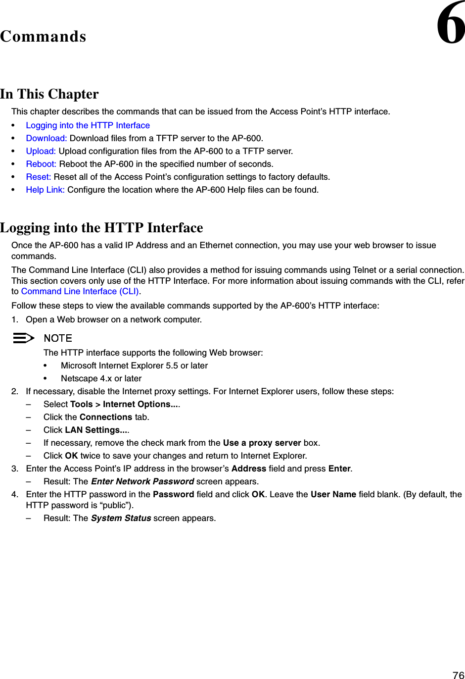
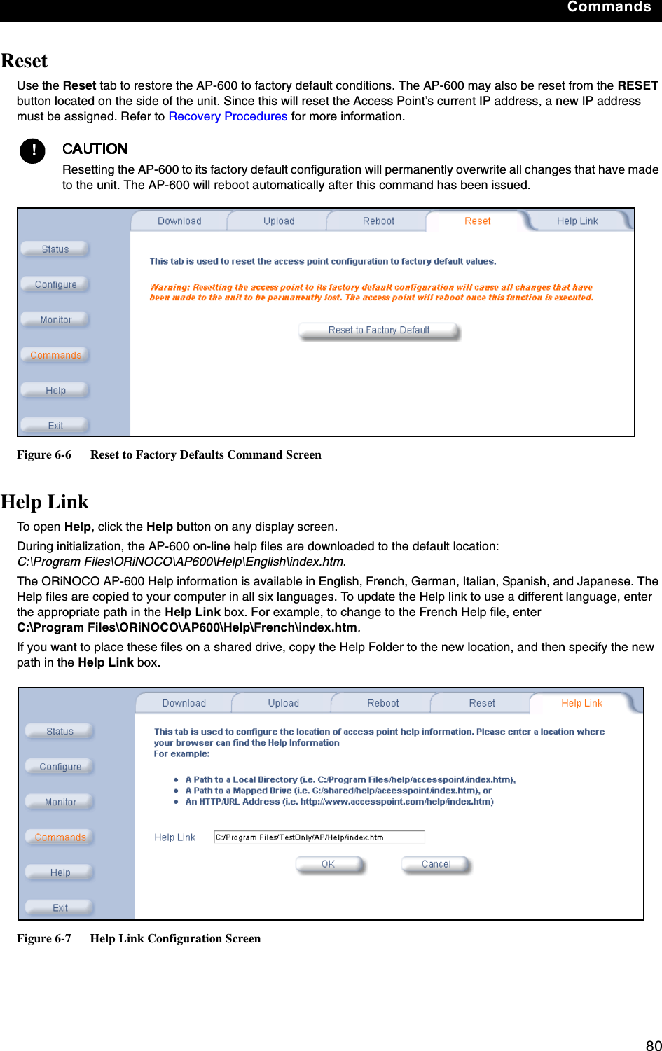
![92ACommand Line Interface (CLI)In This AppendixThis section describes the AP-600’s Command Line (CLI) Interface. CLI commands can be used to initialize, configure, and manage the Access Point.–CLI commands may be entered in real time through a keyboard or submitted with CLI scripts.–The CLI is available through both the Serial Port interface and over the Ethernet interface using Telnet. All CLI commands and parameters are case-sensitive.•General Notes•Command Line Interface (CLI) Variations•CLI Command Types•Using Tables & User Strings•Configuring the AP-600 using CLI commands•Set Basic Configuration Parameters using CLI Commands•Other Network Settings•CLI Monitoring Parameters•Parameter TablesGeneral NotesPrerequisite Skills and KnowledgeTo use this document effectively, you should have a working knowledge of Local Area Networking (LAN) concepts, network access infrastructures, and client-server relationships. In addition, you should be familiar with software setup procedures for typical network operating systems and servers.Notation Conventions•Computer prompts are shown as constant width type. For example: [Device name]>•Information that you input as shown is displayed in bold constant width type. For example: [Device name]> set ipaddr 10.0.0.12•The names of keyboard keys, software buttons, and field names are displayed in bold type. For example: Click the Configure button.•Screen names are displayed in bold italics. For example, the System Status screen.Important Terminology•Configuration Files - Database files containing the current Access Point configuration. Configuration items include the IP Address and other network-specific values. Config files may be downloaded to the Access Point or uploaded for backup or troubleshooting.•Download vs. Upload - Downloads transfer files to the Access Point. Uploads transfer files from the Access Point. The TFTP server performs file transfers in both directions.](https://usermanual.wiki/Proxim-Wireless/A13QBF/User-Guide-301671-Page-98.png)
![Command Line Interface (CLI)95CLI Command TypesThis guide divides CLI Commands into two categories: Operational and Parameter Controls.Operational CLI CommandsThese commands affect Access Point behavior, such as downloading, rebooting, and so on. After entering commands (and parameters, if any) press the Enter key to execute the Command Line.Operational commands include:•?: Typing a question mark lists CLI Commands or parameters, depending on usage (you do not need to type Enter after typing this command)•done, exit, quit: Terminates the CLI session•download: Uses TFTP server to download “image”, “config”, or “bootloader upgrade” files to Access Point•help: Displays general CLI help information or command help information, such as command usage and syntax•history: Remembers commands to help avoid re-entering complex statements•passwd: Sets the Access Point’s CLI password•reboot: Reboots the Access Point in the specified time•search: Lists the parameters in a specified Table•upload: Uses TFTP server to upload “config” files from Access Point to TFTP default directory or specified path? (List Commands) This command can be used in a number of ways to display available commands and parameters.The following table lists each operation and provides a basic example. Following the table are detailed examples and display results for each operation. Example 1. Display Command listTo display the Command List, enter ?.[Device Name]>?Figure A-3 Result of “?” CLI commandExample 2. Display specific CommandsTo show all commands that start with specified letters, enter one or more letters, then ? with no space between letters and ?.[Device Name]>s?Figure A-4 Result of “s?” CLI commandOperation Basic ExampleDisplay the Command List (Example 1) [Device Name]>?Display commands that start with specified letters (Example 2) [Device Name]>s?Display parameters for set and show Commands (Examples 3a and 3b) [Device Name]>set ?[Device Name]>show ipa?Prompt to enter successive parameters for Commands (Example 4) [Device Name]>download ?](https://usermanual.wiki/Proxim-Wireless/A13QBF/User-Guide-301671-Page-101.png)
![Command Line Interface (CLI)96Example 3. Display parameters for set and showExample 3a allows you to see every possible parameter for the set (or show) commands. Notice from example 3a that the list is very long. Example 3b shows how to display a subset of the parameters based on initial parameter letters.Example 3a. Display every parameter that can be changed[Device Name]>set ? Figure A-5 Result of “set ?” CLI commandExample 3b. Display parameters based on letter sequenceThis example shows entries for parameters that start with the letter “i”. The more letters you enter, the fewer the results returned. Notice that there is no space between the letters and the question mark.[Device Name]> show ipa? Figure A-6 Result of “show ipa?” CLI command[Device Name]> show iparp? Figure A-7 Result of “show iparp?” CLI command....](https://usermanual.wiki/Proxim-Wireless/A13QBF/User-Guide-301671-Page-102.png)
![Command Line Interface (CLI)97Example 4. Display Prompts for Successive ParametersEnter the command, a space, and then ?. Then, when the parameter prompt appears, enter the parameter value. Result: The parameter is changed and a new CLI line is echoed with the new value (in the first part of the following example, the value is the IP Address of the TFTP server).After entering one parameter, you may add another ? to the new CLI line to see the next parameter prompt, and so on until you have entered all of the required parameters. The following example shows how this is used for the download Command. The last part of the example shows the completed download Command ready for execution.[Device Name]> download ?<TFTP IP Address>[Device Name]> download 169.254.128.133 ?<File Name>[Device Name]> download 169.254.128.133 apimage ?<file type (config/img/bootloader)>[Device Name]> download 169.254.128.133 apimage img <CR>done, exit, quit Each of the following commands ends a CLI session: [Device Name]> done[Device Name]> exit[Device Name]> quitdownload Downloads the specified file from a TFTP server to the Access Point. Executing download in combination with the asterisks character (“*”) will make use of the previously set TFTP parameters. Executing download without parameters will display command help and usage information.1. Syntax to download a file:Device Name]>download <tftp server address> <path and filename> <file type>Example:[Device Name]>download 192.168.1.100 APImage2 img2. Syntax to display help and usage information:[Device Name]>download3. Syntax to execute the download Command using previously set (stored) TFTP Parameters:[Device Name]>download *helpDisplays instructions on using control-key sequences for navigating a Command Line and displays command information and examples.1. Using help as the only argument:[Device Name]>help](https://usermanual.wiki/Proxim-Wireless/A13QBF/User-Guide-301671-Page-103.png)
![Command Line Interface (CLI)98Figure A-8 Results of “help” CLI command2. Complete command description and command usage can be provided by:[Device Name]>help <command name>[Device Name]><command name> helphistory Shows content of Command History Buffer. The Command History Buffer stores command statements entered in the current session. To avoid re-entering long command statements, use the keyboard “up arrow” (Ctrl-P) and “down arrow” (Ctrl-N) keys to recall previous statements from the Command History Buffer. When the desired statement reappears, press the Enter key to execute, or you may edit the statement before executing it.[Device Name]> historypasswd Changes the CLI Password. [Device Name]> passwd oldpassword newpassword newpasswordreboot Reboots Access Point after specified number of seconds. Specify a value of 0 (zero) for immediate reboot.[Device Name]> reboot 0[Device Name]> reboot 30search Lists the parameters supported by the specified table. This list corresponds to the table information displayed in the HTTP interface. In this example, the CLI returns the list of parameters that make up an entry in the IP Access Table. [Device Name]> search mgmtipaccesstblFigure A-9 Results of “search mgmtipaccesstbl” CLI command](https://usermanual.wiki/Proxim-Wireless/A13QBF/User-Guide-301671-Page-104.png)
![Command Line Interface (CLI)99uploadUploads a text-based configuration file from the AP-600 to the TFTP Server. Executing upload with the asterisk character (“*”) will make use of the previously set/stored TFTP parameters. Executing upload without parameters will display command help and usage information. 1. Syntax to upload a file:[Device Name]>upload <tftp server address> <path and filename> <filetype>Example:[Device Name]>upload 192.168.1.100 APconfig.sys config2. Syntax to display help and usage information:[Device Name]>help upload3. Syntax to execute the upload command using previously set (stored) TFTP Parameters:[Device Name]>upload *Parameter Control CommandsThe following sections cover the two Parameter Control Commands (show and set) and include several tables showing parameter properties. These commands allow you to view (show) all parameters and statistics and to change (set) parameters. •show: To see any Parameter or Statistic value, you can specify a single parameter, a Group, or a Table. •set: Use this CLI Command to change parameter values. You can use a single CLI statement to modify Tables, or you can modify each parameter separately. “show” CLI CommandDisplays the value of the specified parameter, or displays all parameter values of a specified group (parameter table). Groups contain Parameters and Tables. Tables contain parameters for a series of similar entities.To see a definition and syntax example, type only show and then press the Enter key. To see a list of available parameters, enter a question mark (?) after show (example: show ?). Syntax:[Device Name]>show <parameter>[Device Name]>show <group>[Device Name]>show <table>Examples:[Device Name]>show ipaddr[Device Name]>show network[Device Name]>show mgmtipaccesstbl“set” CLI CommandSets (modifies) the value of the specified parameter. To see a definition and syntax example, type only set and then press the Enter key. To see a list of available parameters, enter a space, then a question mark (?) after set (example: set?). Syntax:[Device Name]>set <parameter> <value> [Device Name]>set <table> <index> <argument 1> <value 1> ... <argument N> <value N>Example:[Device Name]>set sysloc “Main Lobby”[Device Name]>set mgmtipaccesstbl 0 ipaddr 10.0.0.10 submask 255.255.0.0 Configuring Objects that Require RebootCertain objects supported by the Access Point require a device reboot in order for the changes to take effect. In order to inform the end-user of this behavior, the CLI provides informational messages when the user has configured an object that requires a reboot. The following messages are displayed as a result of the configuring such object or objects.](https://usermanual.wiki/Proxim-Wireless/A13QBF/User-Guide-301671-Page-105.png)
![Command Line Interface (CLI)100Example 1: Configuring objects that require the device to be rebootedThe following message is displayed every time the user has configured an object that requires the device to be rebooted.[Device Name]>set ipaddr 135.114.73.10The following elements require rebootipaddrExample 2: Executing the “exit”, “quit”, or “done” commands when an object that requires reboot has been configuredIn addition to the above informational message, the CLI also provides a message as a result of the exit, quit, or done command if changes have been made to objects that require reboot. If you make changes to objects that require reboot and execute the exit command the following message is displayed:[Device Name]>exit<CR> OR quit<CR> OR done<CR>Modifications have been made to parameters that require the device to be rebooted. These changes will only take effect after the next reboot.“set” and “show” Command ExamplesIn general, you will use the CLI show Command to view current parameter values and use the CLI set Command to change parameter values. As shown in the following examples, parameters may be set individually or all parameters for a given table can be set with a single statement. Example 1 - Set the Access Point IP Address ParameterSyntax:[Device Name]>set <parameter name> <parameter value> Example:[Device Name]> set ipaddr 10.0.0.12Result: IP Address will be changed when you reboot the Access Point. The CLI reminds you when rebooting is required for a change to take effect. To reboot immediately, enter reboot 0 (zero) at the CLI prompt.Example 2 - Create a table entry or rowUse 0 (zero) as the index to a table when creating an entry. When creating a table row, only the mandatory table elements are required (comment is usually an optional table element). For optional table elements, the default value is generally applied if you do not specify a value.Syntax:[Device Name]>set <table name> <table index> <element 1> <value 1> … <element n> <value n>Example:[Device Name]> set mgmtipaccesstbl 0 ipaddr 10.0.0.10 ipmask 255.255.0.0Result: A new table entry is created for IP address 10.0.0.10 with a 255.255.0.0 subnet mask.Example 3 - Modify a table entry or rowUse the index to be modified and the table elements you would like to modify. For example, suppose the IP Access Table has one entry and you wanted to modify the IP address:[Device Name]>set mgmtipaccesstbl 1 ipaddr 10.0.0.11You can also modify several elements in the table entry. Enter the index number and specific table elements you would like to modify. (Hint: Use the search Command to see the elements that belong to the table.)[Device Name]>set mgmtipaccesstbl 1 ipaddr 10.0.0.12 ipmask 255.255.255.248 cmt “First Row”](https://usermanual.wiki/Proxim-Wireless/A13QBF/User-Guide-301671-Page-106.png)
![Command Line Interface (CLI)101Example 4 - Enable, Disable, or Delete a table entry or rowThe following example illustrates how to manage the second entry in a table.Syntax:[Device Name]>set <Table> index status <enable, disable, delete>[Device Name]>set <Table> index status <1=enable, 2=disable, 3=delete>Example:[Device Name]>set mgmtipaccesstbl 2 status enable[Device Name]>set mgmtipaccesstbl 2 status disable[Device Name]>set mgmtipaccesstbl 2 status delete[Device Name]>set mgmtipaccesstbl 2 status 2You may need to enable a disabled table entry before you can change the entry’s elements.Example 5 - Show the Group ParametersThis example illustrates how to view all elements of a group or table.Syntax:[Device Name]> show <group name>Example:[Device Name]>show networkResult: The CLI displays network group parameters. Note show network and show ip return the same data.Figure A-10 Results of “show network” and “show ip” CLI CommandsExample 6 - Show Individual and Table Parameters1. View a single parameter.Syntax:[Device Name]>show <parameter name>Example:[Device Name]> show ipaddrResult: Displays the Access Point IP address.Figure A-11 Result of “show ipaddr” CLI Command](https://usermanual.wiki/Proxim-Wireless/A13QBF/User-Guide-301671-Page-107.png)
![Command Line Interface (CLI)1022. View all parameters in a table.Syntax:[Device Name]> show <table name>Example:[Device Name]> show mgmtipaccesstblResult: Displays the IP Access Table and its entries.Using Tables & User StringsWorking with TablesEach table element (or parameter) must be specified, as in the example below. [Device Name]>set mgmtipaccesstbl 0 ipaddr 10.0.0.10 ipmask 255.255.0.0Below are the rules for creating, modifying, enabling/disabling, and deleting table entries.•Creation–The table name is required.–The table index is required – for table entry/instance creation the index is always zero (0).–The order in which the table arguments or objects are entered in not important.–Parameters that are not required can be omitted, in which case they will be assigned the default value.•Modification–The table name is required.–The table index is required – to modify the table, “index” must be the index of the entry to be modified.–Only the table objects that are to be modified need to be specified. Not all the table objects are required.–If multiple table objects are to be modified the order in which they are entered is not important.–If the entire table entry is to be modified, all the table objects have to be specified.•Enabling/Disabling–The table name is required.–The table index is required – for table enabling/disabling the index should be the index of the entry to be enabled/disabled.–The entry’s new state (either “enable” or “disable”) is required.•Deletion–The table name is required.–The table index is required – for table deletion the index should be the index of the entry to be deleted.–The word “delete” is required.Using StringsSince there are several string objects supported by the AP-600, a string delimiter is required for the strings to be interpreted correctly by the command line parser. For this CLI implementation, the single quote or double quote character can be used at the beginning and at the end of the string. For example:[Device Name]> set sysname Lobby - Does not need quote marks[Device Name]> set sysname “Front Lobby” - Requires quote marks. The scenarios supported by this CLI are:The string delimiter does not have to be used for every string object. The single quote or double quote only has to be used for string objects that contain blank space characters. If the string object being used does not contain blank spaces, then the string delimiters, single or double quotes, mentioned in this section are not required.“My Desk in Nieuwegein”Double Quotes‘My Desk in Nieuwegein’Single Quotes“My ‘Desk’ in Nieuwegein”Single Quotes within Double Quotes‘My “Desk” in Nieuwegein’Double Quotes within Single Quotes“Daniel’s Desk in Nieuwegein”One Single Quote within Double Quotes‘Daniel”s Desk in Nieuwegein’One Double Quote within Single Quotes](https://usermanual.wiki/Proxim-Wireless/A13QBF/User-Guide-301671-Page-108.png)
![Command Line Interface (CLI)103Configuring the AP-600 using CLI commandsLog into the AP-600 using HyperTerminal1. Open your terminal emulation program (like HyperTerminal) and set the following connection properties:•Com Port: <COM1, COM2, etc., depending on your computer>•Baud rate: 9600•Data Bits: 8•Stop bits: 1•Flow Control: None•Parity: None2. Under File -> Properties -> Settings -> ASCII Setup, enable the Send line ends with line feeds option. Result: HyperTerminal sends a line return at the end of each line of code.3. Enter the CLI password (default is public).Proxim recommends changing your default passwords immediately. To perform this operation using CLI commands, refer to Change Passwords.Log into the AP-600 using TelnetThe CLI commands can be used to access, configure, and manage the AP-600 using Telnet. Follow these steps:1. Confirm that your computer’s IP address is in the same IP subnet as the AP-600.If you have not previously configured the Access Point’s IP address and do not have a DHCP server on the network, the Access Point will default to an IP address of 169.254.128.132.2. Go to the DOS command prompt on your computer.3. Type telnet <IP Address of the unit>.4. Enter the CLI password (default is public).Proxim recommends changing your default passwords immediately. To perform this operation using CLI commands, refer to Change Passwords.Set Basic Configuration Parameters using CLI CommandsThere are a few basic configuration parameters that you may want to setup right away when you receive the AP-600. For example:–Set System Name, Location and Contact Information–Set Static IP Address for the AP-600–Download an AP-600 Configuration File from your TFTP Server–Set Network Names for the Wireless Interface–Set WEP Encryption for the Wireless Interface–Download an AP-600 Configuration File from your TFTP Server–Backup your AP-600 Configuration FileSet System Name, Location and Contact Information[Device Name]>set sysname <system name> sysloc <Unit Location>[Device Name]>set sysctname <Contact Name (person responsible for system)>[Device Name]>set sysctphone <Contact Phone Number> sysctemail <Contact E-mail address>[Device Name]>show system](https://usermanual.wiki/Proxim-Wireless/A13QBF/User-Guide-301671-Page-109.png)
![Command Line Interface (CLI)104Figure A-12 Result of “show system” CLI CommandSet Static IP Address for the AP-600The IP Subnet Mask of the AP-600 must match your network’s Subnet Mask.[Device Name]>set ipaddrtype static [Device Name]>set ipaddr <fixed IP address of unit>[Device Name]>set ipsubmask <IP Mask (default = 255.0.0.0)>[Device Name]>set ipgw <gateway IP address (default = 169.254.128.133)>[Device Name]>show networkChange Passwords[Device Name]>passwd <Old Password> <New Password> <Confirm Password> (CLI password)[Device Name]>set httppasswd <New Password> (HTTP interface password)[Device Name]>set snmprpasswd <New Password> (SNMP read password)[Device Name]>set snmprwpasswd <New Password> (SNMP read/write)[Device Name]>reboot 0!Proxim strongly urges you to change the default passwords to restrict access to your network devices to authorized personnel. If you lose or forget your password settings, you can always perform the Reset to Factory Default Procedure.Set Network Names for the Wireless Interface[Device Name]>set wif 3 netname <Network Name (SSID) for wireless interface>[Device Name]>show wifFigure A-13 Results of “show wif” CLI command for an AP-600a](https://usermanual.wiki/Proxim-Wireless/A13QBF/User-Guide-301671-Page-110.png)
![Command Line Interface (CLI)105Set WEP Encryption for the Wireless Interface!Wireless clients must be configured with the same encryption key to be able to communicate with the AP-600. The AP-600 can only support one Key Length (so each of the configured keys must have the same length). The available key sizes vary based on the Access Point’s model. See Security Encryption Key Length Table for more information.You can set up to four encryption keys. This example describes setting encryption Key 1 on the wireless card in Slot A.[Device Name]>set wifsec 3 encryptstatus enable encryptkey1 <WEP key (number of characters vary depending on AP model)> encryptkeytx 1[Device Name]>show wifsecFigure A-14 Result of “show wifsec” CLI CommandDownload an AP-600 Configuration File from your TFTP ServerBegin by starting your TFTP program. It must be running and configured to transmit and receive.[Device Name]>set tftpfilename <file name> tftpfiletype config tftpipaddr <IP address of your TFTP server>[Device Name]>show tftp (to ensure the filename, file type, and the IP address are correct)[Device Name]>download *[Device Name]>reboot 0After following the complete process (above) once, you can download a file of the same name (so long as all the other parameters are the same), with the following command:[Device Name]>download *Backup your AP-600 Configuration File Begin by starting your TFTP program. It must be running and configured to transmit and receive.[Device Name]>upload <TFTP Server IP address> <tftpfilename (such as “config.sys”)> config[Device Name]>show tftp (to ensure the filename, file type, and the IP address are correct)After setting the TFTP parameters, you can backup your current file (so long as all the other parameters are the same), with the following command:[Device Name]>upload *](https://usermanual.wiki/Proxim-Wireless/A13QBF/User-Guide-301671-Page-111.png)
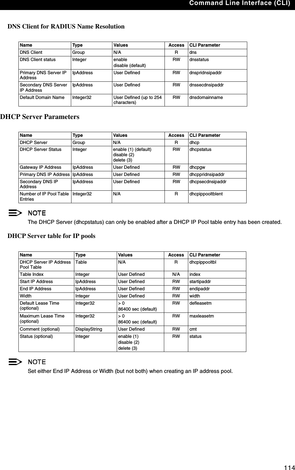
![Command Line Interface (CLI)106Other Network SettingsThere are other configuration settings that you may want to set for the AP-600. Some of them are listed below. –Configure the AP-600 as a DHCP Server–Configure the DNS Client–Maintain Client Connections using Link Integrity–Change your Wireless Interface Settings–Set Ethernet Speed and Transmission Mode–Set Interface Management Services–Configure MAC Access Control–Set RADIUS ParametersRefer to Advanced Configuration for more information on these settings.Configure the AP-600 as a DHCP ServerYou must have at least one entry in the DHCP Server IP Address Pool Table before you can set the DHCP Server Status to Enable.[Device Name]>set dhcpstatus disable [Device Name]>set dhcpippooltbl 0 startipaddr <start ip address> endipaddr <end ip address> [Device Name]>set dhcpgw <gateway ip address>[Device Name]>set dhcppridnsipaddr <primary dns ip address>[Device Name]>set dhcpsecdnsipaddr <secondary dns ip address> [Device Name]>set dhcpstatus enable[Device Name]>reboot 0!Before enabling this feature, confirm that the IP address pools you have configured are valid addresses on the network and do not overlap the addresses assigned by any other DHCP server on the network. Enabling this feature with incorrect address pools will cause problems on your network.Configure the DNS Client[Device Name]>set dnsstatus enable [Device Name]>set dnsprisvripaddr <IP address of primary DNS server> [Device Name]>set dnssecsvripaddr <IP address of secondary DNS server> [Device Name]>set dnsdomainname <default domain name>[Device Name]>show dnsFigure A-15 Results of “show dns” CLI command](https://usermanual.wiki/Proxim-Wireless/A13QBF/User-Guide-301671-Page-112.png)
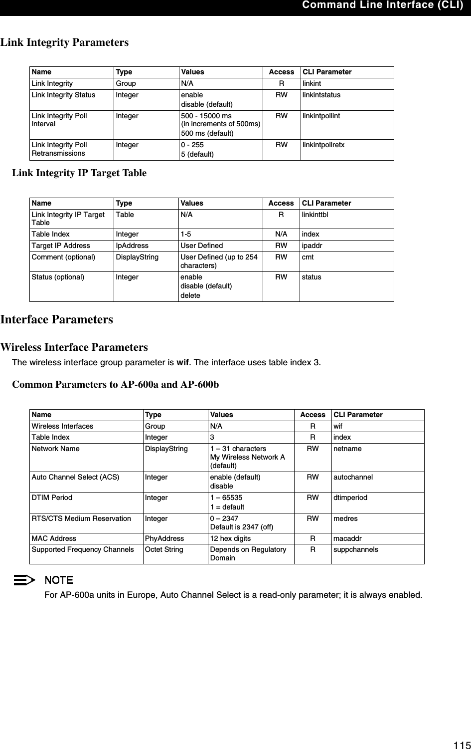
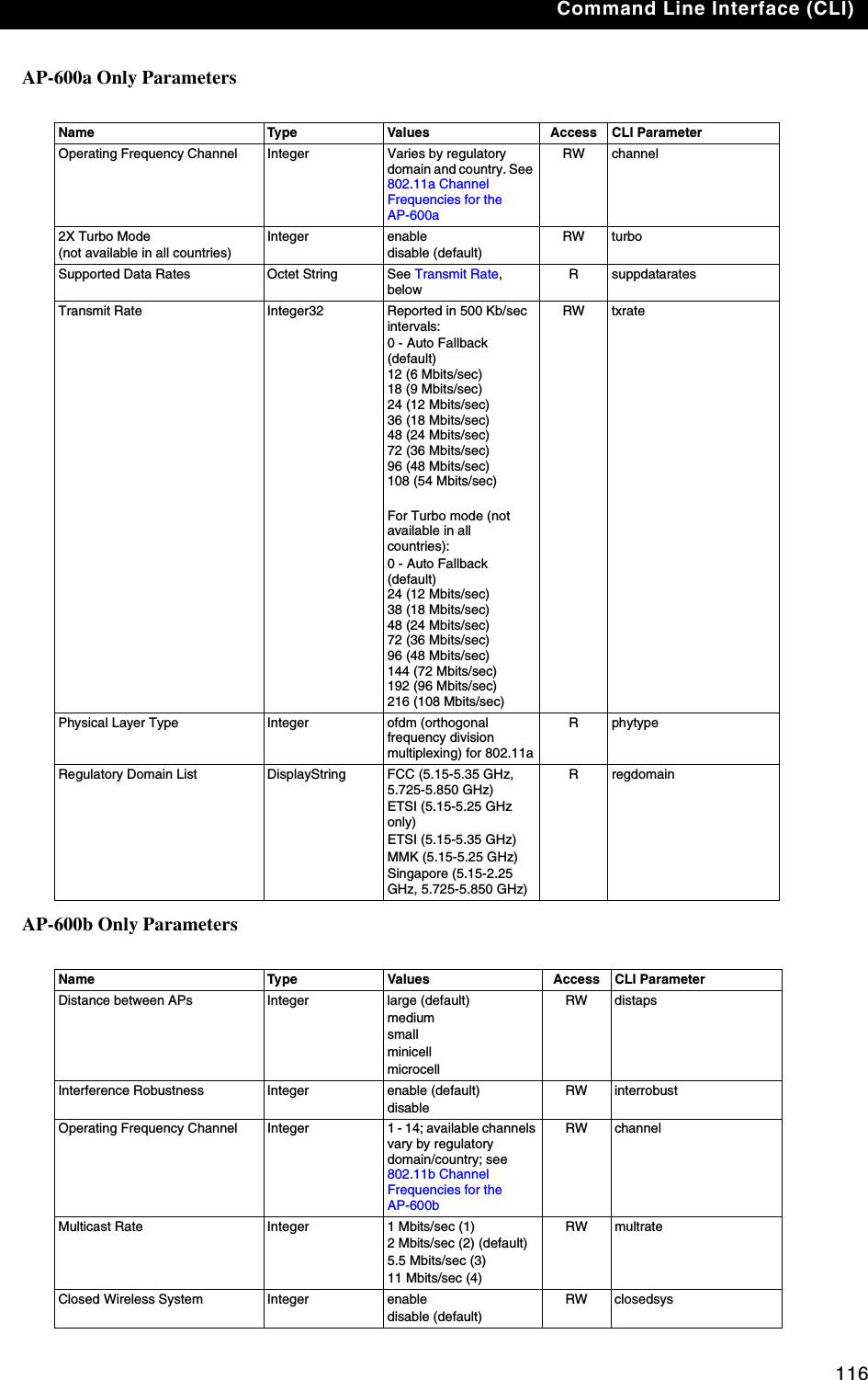
![Command Line Interface (CLI)107Maintain Client Connections using Link Integrity[Device Name]>show linkinttbl (this shows the current links)[Device Name]>set linkinttbl <1-5 (depending on what table row you wish to address)> ipaddr <ip address of the host computer you want to check>[Device Name]>set linkintpollint <the interval between link integrity checks>[Device Name]>set linkintpollretx <number of times to retransmit before considering the link down>[Device Name]>set linkintstatus enable[Device Name]>show linkinttbl (confirm new settings)[Device Name]>reboot 0Change your Wireless Interface Settings See Wireless (AP-600a) or Wireless (AP-600b) for information on the parameters listed below.Autochannel Select (ACS)ACS is enabled by default. Reboot after disabling or enabling ACS.[Device Name]>set wif 3 autochannel <enable/disable>[Device Name]>reboot 0Enable 2X Turbo Mode (AP-600a Only)[Device Name]>set wif 3 turbo <enable/disable>[Device Name]>reboot 0Enable/Disable Interference Robustness (AP-600b Only)[Device Name]>set wif 3 interrobust <enable/disable>Enable/Disable Closed System (AP-600b Only)[Device Name]>set wif 3 closedsys <enable/disable>When disabled, a client configured with the Network Name “ANY” can connect to the AP-600b. This feature is not currently available for the AP-600a.Enable/Disable Load Balancing (AP-600b Only)[Device Name]>set wif 3 ldbalance <enable/disable>Enable/Disable Medium Density Distribution (AP-600b Only)[Device Name]>set wif 3 meddendistrib <enable/disable>](https://usermanual.wiki/Proxim-Wireless/A13QBF/User-Guide-301671-Page-113.png)
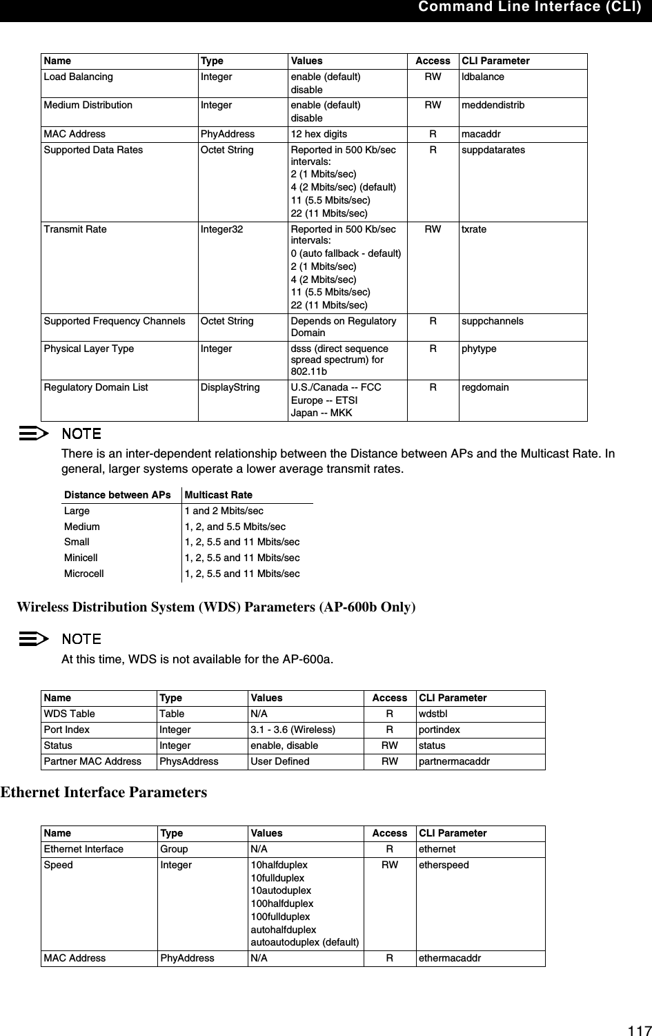
![Command Line Interface (CLI)108Set the Distance Between APs (AP-600b Only)[Device Name]>set wif 3 distaps <large, medium, small, minicell, microcell>[Device Name]>reboot 0The distance between APs should not be approximated. It is calculated by means of a manual Site Survey, in which an AP-600 is set up and clients are tested throughout the area to determine signal strength and coverage, and local limits such as physical interference are investigated. From these measurements the appropriate cell size and density is determined, and the optimum distance between APs is calculated to suit your particular business requirements.Set the Multicast Rate (AP-600b Only)[Device Name]>set wif 3 multrate <1,2,5.5,11 (Mbits/sec)>The Distance Between APs must be set before the Multicast Rate. Set Ethernet Speed and Transmission Mode[Device Name]>set etherspeed <value (see below)>[Device Name]>reboot 0Set Interface Management ServicesEdit Management IP Access Table[Device Name]>set mgmtipaccesstbl <index> ipaddr <IP address> ipmask <subnet mask>Configure Management Ports[Device Name]>set snmpifbitmask <0 - 7 (default is 7 see below)>[Device Name]>set httpifbitmask <0 - 7 (default is 7 see below)>[Device Name]>set telifbitmask <0 - 7 (default is 7 see below)>Choose from the following values:Set Communication Ports[Device Name]>set httpport <HTTP port number (default is 80)> [Device Name]>set telport <Telnet port number (default is 23)> Ethernet Speed and Transmission Mode Value10 Mbits/sec - half duplex 10halfduplex10 Mbits/sec - full duplex 10fullduplex10 Mbits/sec - auto duplex 10autoduplex100 Mbits/sec - half duplex 100halfduplex100 Mbits/sec - full duplex 100fullduplexAuto Speed - half duplex autohalfduplexAuto Speed - auto duplex autoautoduplex (default)Interface bitmask Description0 or 2 = disable (all interfaces) All management channels disabled1 or 3 = Ethernet only Ethernet only enabled4 or 6 = Wireless only Wireless only enabled5 or 7 = all interfaces All management channels enabled](https://usermanual.wiki/Proxim-Wireless/A13QBF/User-Guide-301671-Page-114.png)
![Command Line Interface (CLI)109Set Telnet Session Timeouts[Device Name]>set tellogintout <time in seconds between 1 and 300 (default is 30)> [Device Name]>set telsessiontout <time in seconds between 1 and 36000 (default is 900)>Configure Serial Port InterfaceTo avoid unexpected performance issues, leave Flow Control at the default setting (none) unless you are sure what this setting should be.[Device Name]>set serbaudrate <2400, 4800, 9600, 19200, 38400, 57600> [Device Name]>set serflowctrl <none, xon/xoff>[Device Name]>show serial Figure A-16 Result of “show serial” CLI CommandConfigure Syslog[Device Name]>set syslogpriority <1-7 (default is 6)> [Device Name]>set syslogstatus <enable/disable>Configure Intra BSS[Device Name]>set intrabssoptype <passthru (default)/block)> Configure MAC Access ControlSetup MAC (Address) Access Control[Device Name]>set macaclstatus enable [Device Name]>set macacloptype <passthru, block>[Device Name]>reboot 0Add an Entry to the MAC Access Control Table[Device Name]>set macacltbl <index> macaddr <MAC Address> status enable[Device Name]>show macacltblDisable or Delete an Entry in the MAC Access Control Table[Device Name]>set macacltbl <index> status <disable/delete>[Device Name]>show macacltblFor larger networks that include multiple Access Points, you may prefer to maintain this list on a centralized location using the RADIUS parameters (see Set RADIUS Parameters).](https://usermanual.wiki/Proxim-Wireless/A13QBF/User-Guide-301671-Page-115.png)
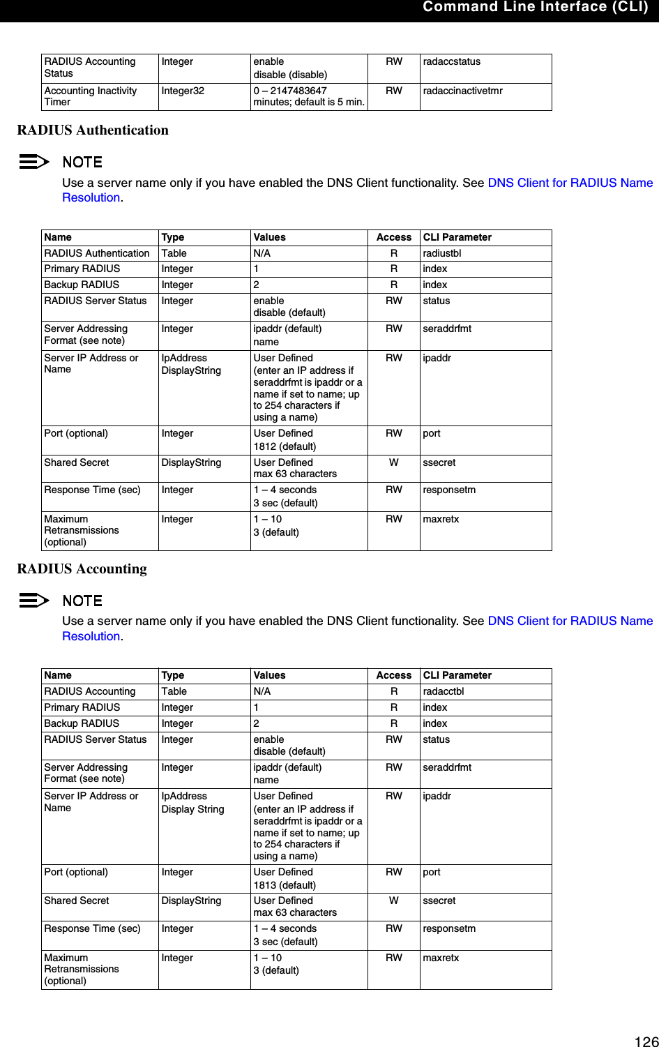
![Command Line Interface (CLI)110Configure 802.1x Authentication[Device Name]>set secconfig <none, 802.1x, mixed> [Device Name]>set secenckeylentbl 3 enckeylen <64bits, 128bits, 152bits ( 1 5 2 b i t s available with AP-600a only)>[Device Name]>set secrekeyint <60 – 65535 seconds; default is 900 sec> [Device Name]>reboot 0 If you set Security to 802.1x or Mixed, you also need to configure the RADIUS parameters. If you set Security to Mixed, you also need to configure WEP Encryption settings. See 802.1x for details.Set RADIUS ParametersConfigure RADIUS Authentication server[Device Name]>set radiustbl <index> status enable seraddrfmt <ipaddr or name> ipaddr <RADIUS IP address or name> port <user defined> ssecret <user defined> responsetm <1 to 4 seconds> maxretx <1 to 10 times> [Device Name]>show radiustblFigure A-17 Results of “show radiustbl” CLI commandEnable RADIUS MAC Access Control[Device Name]>set radmacaccctrl enable [Device Name]>reboot 0Set MAC Address Format Type[Device Name]>set radmacaddrformat <dashdelimited, colondelimited, singledashdelimited, nodelimiter>Set Authentication Lifetime[Device Name]>set radauthlifetm <60-43200 seconds; default is 900>Enable RADIUS Accounting[Device Name]>set radaccstatus enable[Device Name]>set radaccinactivetmr <inactivity timer in minutes>[Device Name]>show radius](https://usermanual.wiki/Proxim-Wireless/A13QBF/User-Guide-301671-Page-116.png)
![Command Line Interface (CLI)111Figure A-18 Result of “show radius” CLI CommandConfigure RADIUS Accounting server[Device Name]>set radacctbl <index> status <enable> seraddrfmt <ipaddr or name> ipaddr <RADIUS IP address or name> port <user defined> ssecret <user defined> responsetm <1 to 4 seconds> maxretx <1 to 10 times>[Device Name]>show radacctblFigure A-19 Results of “show radacctbl” CLI commandCLI Monitoring ParametersUsing the show command with the following table parameters will display operating statistics for the AP-600 (these are the same statistics that are described in Monitor Information for the HTTP Web interface).–staticmp: Displays the ICMP Statistics.–statarptbl: Displays the IP ARP Table Statistics.–statbridgetbl: Displays the Learn Table.–statiapp: Displays the IAPP Statistics.–statradius: Displays the RADIUS Authentication Statistics.–statif: Displays information and statistics about the Ethernet and wireless interfaces.–stat802.11: Displays additional statistics for the wireless interfaces.–statethernet: Displays additional statistics for the Ethernet interface.](https://usermanual.wiki/Proxim-Wireless/A13QBF/User-Guide-301671-Page-117.png)
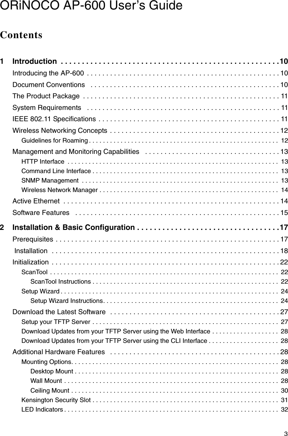
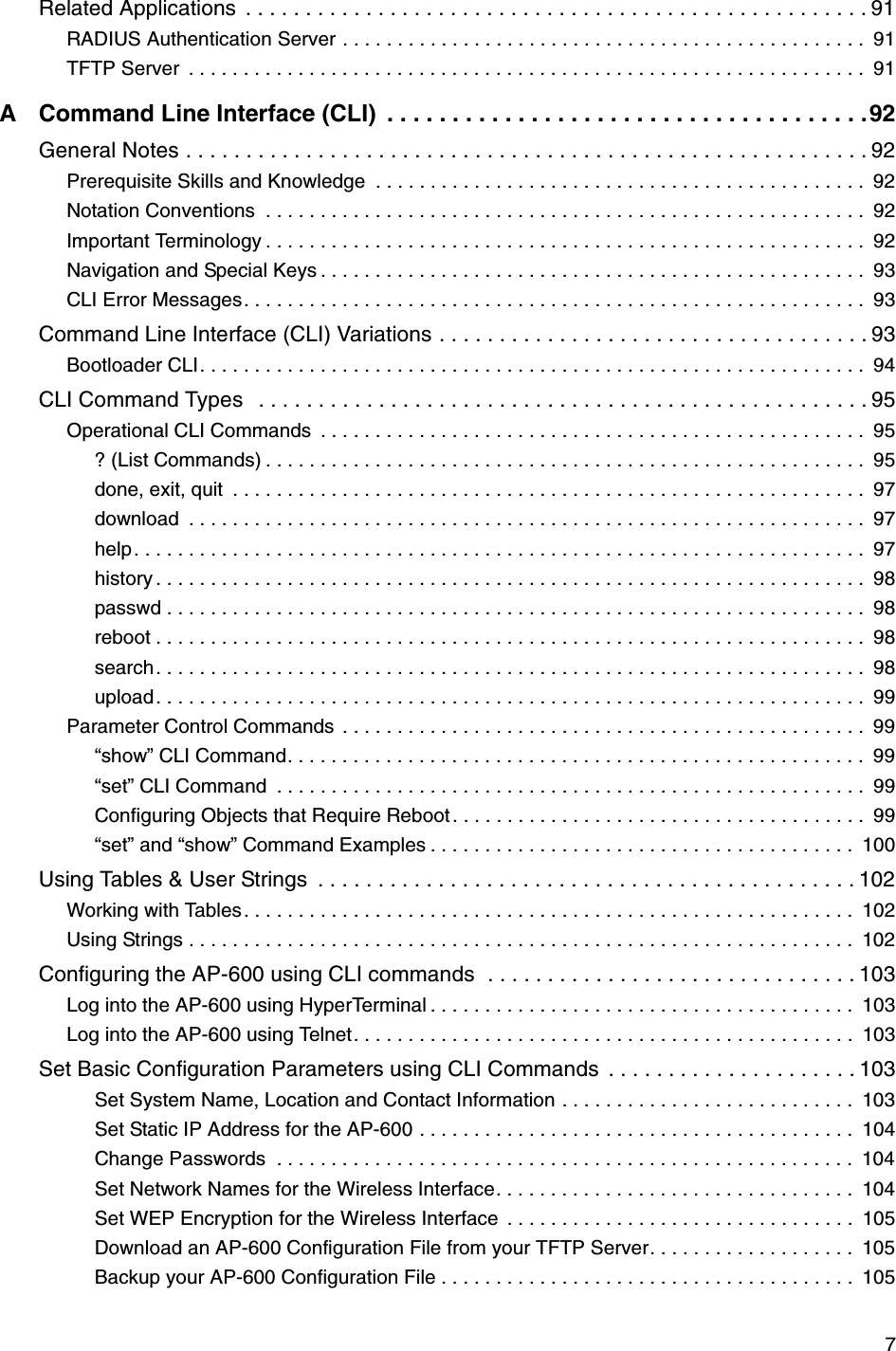
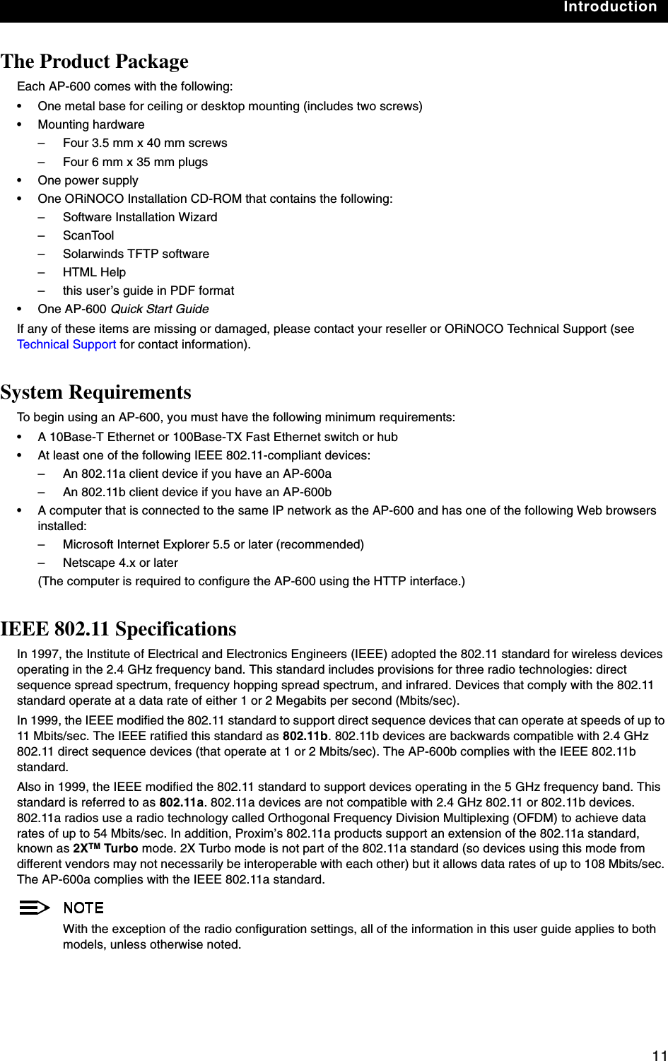
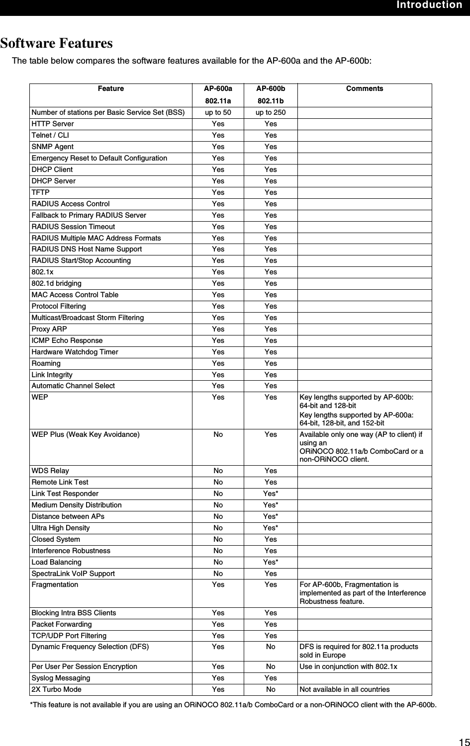
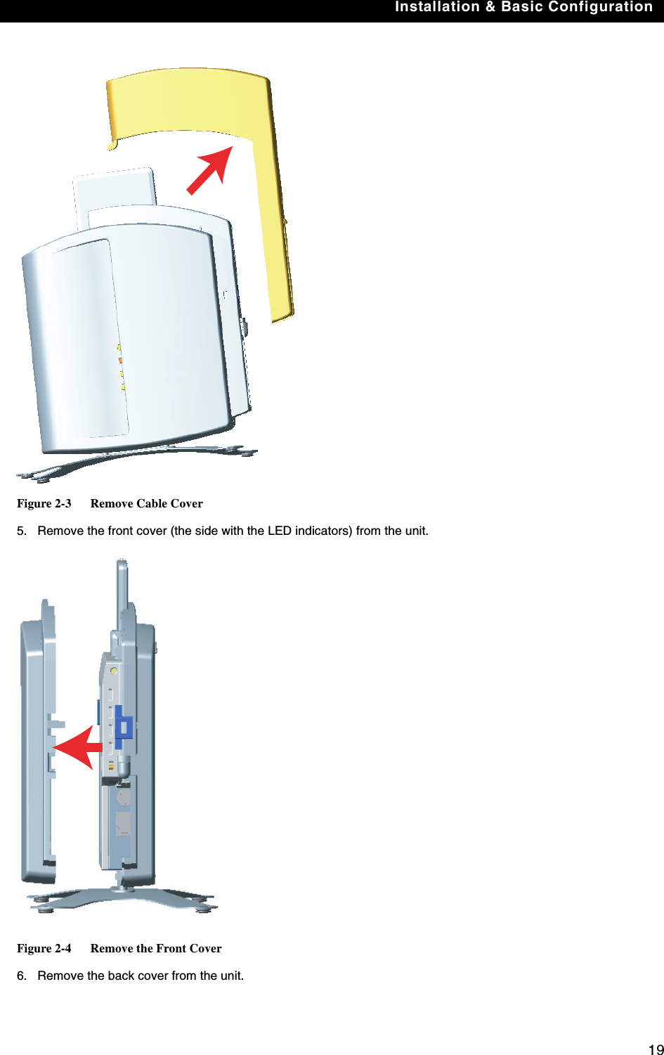
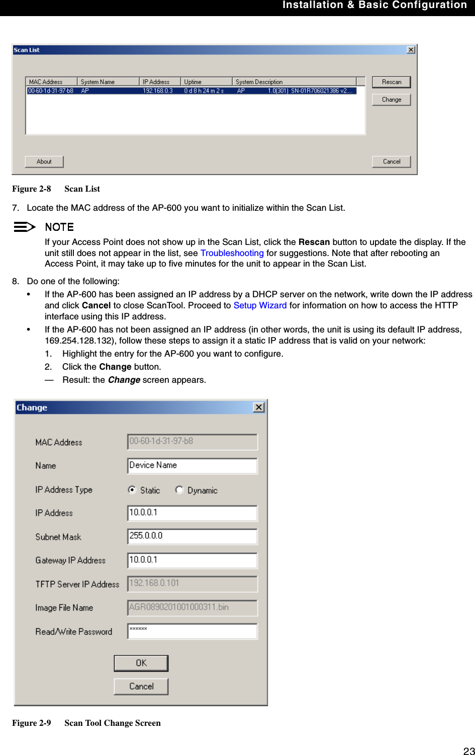
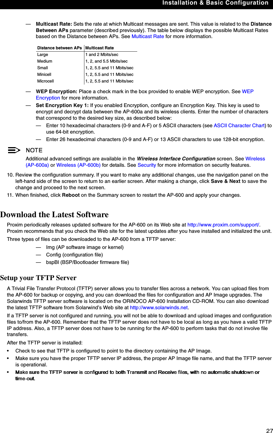
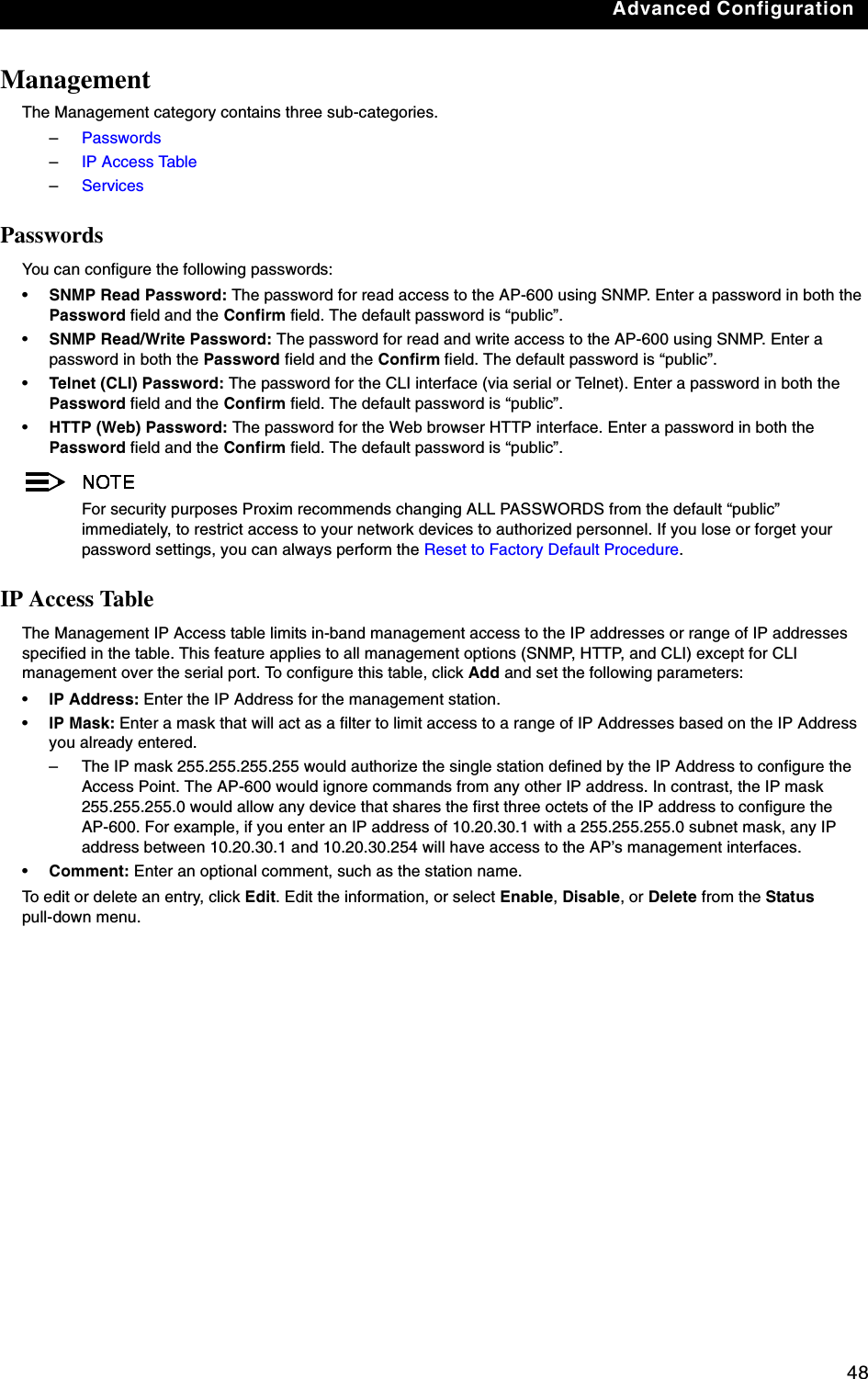
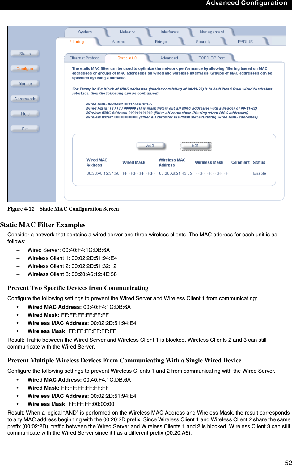
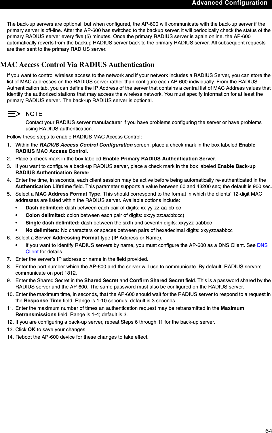
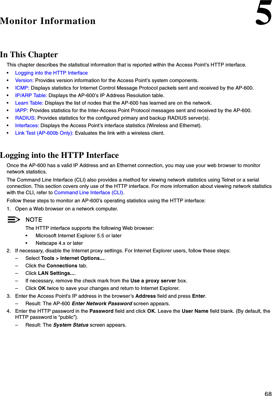
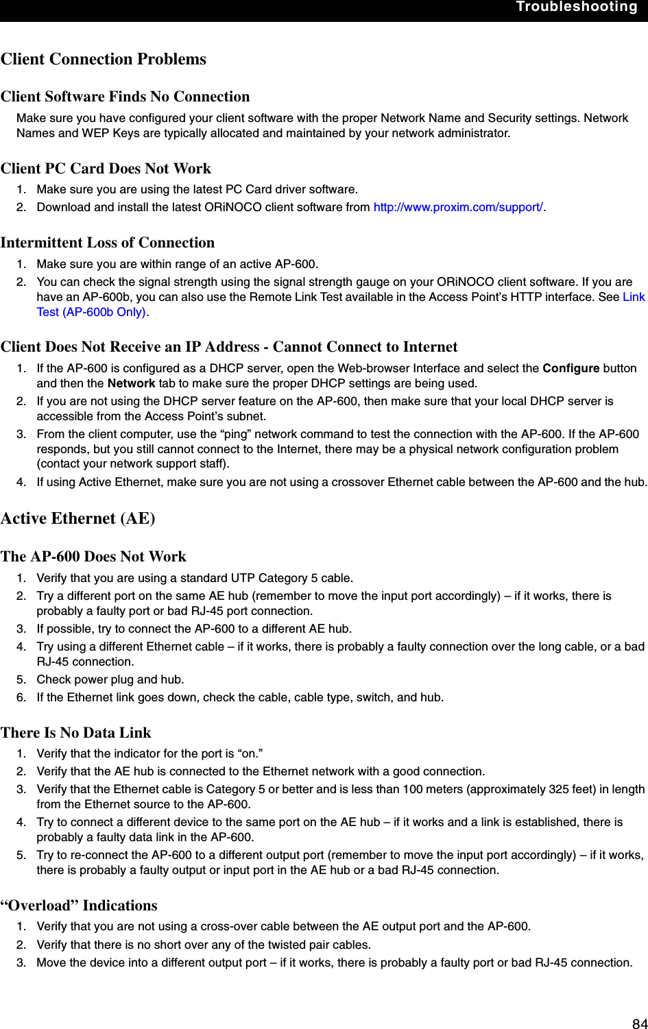
![128BASCII Character ChartYou can configure WEP Encryption Keys in either Hexadecimal or ASCII format. Hexadecimal digits are 0-9 and A-F (not case sensitive). ASCII characters are 0-9, A-F, a-f (case sensitive), and punctuation marks. Each ASCII character corresponds to two hexadecimal digits.The table below lists the ASCII characters that you can use to configure WEP Encryption Keys. It also lists the Hexadecimal equivalent for each ASCII character.ASCII CharacterHex EquivalentASCII CharacterHex EquivalentASCII CharacterHex EquivalentASCII CharacterHex Equivalent!21 939 Q51 i69"22 :3A R52 j6A#23 ;3B S53 k6B$24 <3C T54 l6C%25 =3D U55 m6D&26 >3E V56 n6E'27 ?3F W57 o6F(28 @40 X58 p70)29 A41 Y59 q71*2A B42 Z5A r72+2B C43 [5B s73,2C D44 \5C t74-2D E45 ]5D u75.2E F46 ^5E v76/2F G47 _5F w77030 H48 `60 x78131 I49 a61 y79232 J4A b62 z7A333 K4B c63 {7B434 L4C d64 |7C535 M4D e65 }7D636 N4E f66 ~7E737 O4F g67838 P50 h68](https://usermanual.wiki/Proxim-Wireless/A13QBF/User-Guide-301671-Page-134.png)