Proxim Wireless A13QBF Wireless LAN and mini-PCI Module User Manual alpha1
Proxim Wireless Corporation Wireless LAN and mini-PCI Module alpha1
Manual

The Ca
p
acity to Do G
r
eat Thin
g
s
.
User Guide for the
ORiNOCO AP-600
2
Copyright
© 2002 Proxim Corporation. All rights reserved. Covered by one or more of the following U.S. patents: 5,231,634;
5,875,179; 6,006,090; 5,809,060; 6,075,812; 5,077,753. This user’s guide and the software described in it are
copyrighted with all rights reserved. No part of this publication may be reproduced, transmitted, transcribed, stored in a
retrieval system, or translated into any language in any form by any means without the written permission of Proxim
Corporation.
Trademarks
ORiNOCO is a registered trademark, and 2x, Proxim, and the Proxim logo are trademarks of Proxim Corporation. All
other trademarks mentioned herein are the property of their respective owners.
ORiNOCO AP-600 User’s Guide
Part # PX-024124-A
Rev. 01
12_02
3
ORiNOCO AP-600 User’s Guide
Contents
1 Introduction . . . . . . . . . . . . . . . . . . . . . . . . . . . . . . . . . . . . . . . . . . . . . . . . . . . .10
Introducing the AP-600 . . . . . . . . . . . . . . . . . . . . . . . . . . . . . . . . . . . . . . . . . . . . . . . . . . 10
Document Conventions . . . . . . . . . . . . . . . . . . . . . . . . . . . . . . . . . . . . . . . . . . . . . . . . . 10
The Product Package . . . . . . . . . . . . . . . . . . . . . . . . . . . . . . . . . . . . . . . . . . . . . . . . . . . 11
System Requirements . . . . . . . . . . . . . . . . . . . . . . . . . . . . . . . . . . . . . . . . . . . . . . . . . . 11
IEEE 802.11 Specifications . . . . . . . . . . . . . . . . . . . . . . . . . . . . . . . . . . . . . . . . . . . . . . . 11
Wireless Networking Concepts . . . . . . . . . . . . . . . . . . . . . . . . . . . . . . . . . . . . . . . . . . . . 12
Guidelines for Roaming . . . . . . . . . . . . . . . . . . . . . . . . . . . . . . . . . . . . . . . . . . . . . . . . . . . . . . 12
Management and Monitoring Capabilities . . . . . . . . . . . . . . . . . . . . . . . . . . . . . . . . . . . 13
HTTP Interface . . . . . . . . . . . . . . . . . . . . . . . . . . . . . . . . . . . . . . . . . . . . . . . . . . . . . . . . . . . . 13
Command Line Interface . . . . . . . . . . . . . . . . . . . . . . . . . . . . . . . . . . . . . . . . . . . . . . . . . . . . . 13
SNMP Management . . . . . . . . . . . . . . . . . . . . . . . . . . . . . . . . . . . . . . . . . . . . . . . . . . . . . . . . 13
Wireless Network Manager . . . . . . . . . . . . . . . . . . . . . . . . . . . . . . . . . . . . . . . . . . . . . . . . . . . 14
Active Ethernet . . . . . . . . . . . . . . . . . . . . . . . . . . . . . . . . . . . . . . . . . . . . . . . . . . . . . . . . 14
Software Features . . . . . . . . . . . . . . . . . . . . . . . . . . . . . . . . . . . . . . . . . . . . . . . . . . . . . 15
2 Installation & Basic Configuration . . . . . . . . . . . . . . . . . . . . . . . . . . . . . . . . . .17
Prerequisites . . . . . . . . . . . . . . . . . . . . . . . . . . . . . . . . . . . . . . . . . . . . . . . . . . . . . . . . . .17
Installation . . . . . . . . . . . . . . . . . . . . . . . . . . . . . . . . . . . . . . . . . . . . . . . . . . . . . . . . . . . 18
Initialization . . . . . . . . . . . . . . . . . . . . . . . . . . . . . . . . . . . . . . . . . . . . . . . . . . . . . . . . . . . 22
ScanTool . . . . . . . . . . . . . . . . . . . . . . . . . . . . . . . . . . . . . . . . . . . . . . . . . . . . . . . . . . . . . . . . . 22
ScanTool Instructions . . . . . . . . . . . . . . . . . . . . . . . . . . . . . . . . . . . . . . . . . . . . . . . . . . . . . 22
Setup Wizard . . . . . . . . . . . . . . . . . . . . . . . . . . . . . . . . . . . . . . . . . . . . . . . . . . . . . . . . . . . . . . 24
Setup Wizard Instructions. . . . . . . . . . . . . . . . . . . . . . . . . . . . . . . . . . . . . . . . . . . . . . . . . . 24
Download the Latest Software . . . . . . . . . . . . . . . . . . . . . . . . . . . . . . . . . . . . . . . . . . . . 27
Setup your TFTP Server . . . . . . . . . . . . . . . . . . . . . . . . . . . . . . . . . . . . . . . . . . . . . . . . . . . . . 27
Download Updates from your TFTP Server using the Web Interface . . . . . . . . . . . . . . . . . . . 28
Download Updates from your TFTP Server using the CLI Interface . . . . . . . . . . . . . . . . . . . . 28
Additional Hardware Features . . . . . . . . . . . . . . . . . . . . . . . . . . . . . . . . . . . . . . . . . . . . 28
Mounting Options. . . . . . . . . . . . . . . . . . . . . . . . . . . . . . . . . . . . . . . . . . . . . . . . . . . . . . . . . . . 28
Desktop Mount . . . . . . . . . . . . . . . . . . . . . . . . . . . . . . . . . . . . . . . . . . . . . . . . . . . . . . . . . . 28
Wall Mount . . . . . . . . . . . . . . . . . . . . . . . . . . . . . . . . . . . . . . . . . . . . . . . . . . . . . . . . . . . . . 28
Ceiling Mount . . . . . . . . . . . . . . . . . . . . . . . . . . . . . . . . . . . . . . . . . . . . . . . . . . . . . . . . . . . 30
Kensington Security Slot . . . . . . . . . . . . . . . . . . . . . . . . . . . . . . . . . . . . . . . . . . . . . . . . . . . . . 31
LED Indicators . . . . . . . . . . . . . . . . . . . . . . . . . . . . . . . . . . . . . . . . . . . . . . . . . . . . . . . . . . . . . 32
4
3 Status Information . . . . . . . . . . . . . . . . . . . . . . . . . . . . . . . . . . . . . . . . . . . . . . .33
Logging into the HTTP Interface . . . . . . . . . . . . . . . . . . . . . . . . . . . . . . . . . . . . . . . . . . . 33
System Status . . . . . . . . . . . . . . . . . . . . . . . . . . . . . . . . . . . . . . . . . . . . . . . . . . . . . . . . . 34
4 Advanced Configuration . . . . . . . . . . . . . . . . . . . . . . . . . . . . . . . . . . . . . . . . . .35
Configuring the AP-600 Using the HTTP Interface . . . . . . . . . . . . . . . . . . . . . . . . . . . . . 35
System . . . . . . . . . . . . . . . . . . . . . . . . . . . . . . . . . . . . . . . . . . . . . . . . . . . . . . . . . . . . . . 37
Network . . . . . . . . . . . . . . . . . . . . . . . . . . . . . . . . . . . . . . . . . . . . . . . . . . . . . . . . . . . . . . 37
IP Configuration . . . . . . . . . . . . . . . . . . . . . . . . . . . . . . . . . . . . . . . . . . . . . . . . . . . . . . . . . . . . 37
DHCP Server . . . . . . . . . . . . . . . . . . . . . . . . . . . . . . . . . . . . . . . . . . . . . . . . . . . . . . . . . . . . . . 38
Link Integrity . . . . . . . . . . . . . . . . . . . . . . . . . . . . . . . . . . . . . . . . . . . . . . . . . . . . . . . . . . . . . . 39
Interfaces . . . . . . . . . . . . . . . . . . . . . . . . . . . . . . . . . . . . . . . . . . . . . . . . . . . . . . . . . . . . 40
Wireless (AP-600a) . . . . . . . . . . . . . . . . . . . . . . . . . . . . . . . . . . . . . . . . . . . . . . . . . . . . . . . . . 40
Dynamic Frequency Selection (DFS) . . . . . . . . . . . . . . . . . . . . . . . . . . . . . . . . . . . . . . . . . 41
RTS/CTS Medium Reservation . . . . . . . . . . . . . . . . . . . . . . . . . . . . . . . . . . . . . . . . . . . . . 42
Wireless (AP-600b) . . . . . . . . . . . . . . . . . . . . . . . . . . . . . . . . . . . . . . . . . . . . . . . . . . . . . . . . . 42
Distance Between APs . . . . . . . . . . . . . . . . . . . . . . . . . . . . . . . . . . . . . . . . . . . . . . . . . . . . 44
Multicast Rate. . . . . . . . . . . . . . . . . . . . . . . . . . . . . . . . . . . . . . . . . . . . . . . . . . . . . . . . . . . 45
Wireless Distribution System (WDS) . . . . . . . . . . . . . . . . . . . . . . . . . . . . . . . . . . . . . . . . . 46
Ethernet . . . . . . . . . . . . . . . . . . . . . . . . . . . . . . . . . . . . . . . . . . . . . . . . . . . . . . . . . . . . . . . . . . 47
Management . . . . . . . . . . . . . . . . . . . . . . . . . . . . . . . . . . . . . . . . . . . . . . . . . . . . . . . . . . 48
Passwords . . . . . . . . . . . . . . . . . . . . . . . . . . . . . . . . . . . . . . . . . . . . . . . . . . . . . . . . . . . . . . . . 48
IP Access Table . . . . . . . . . . . . . . . . . . . . . . . . . . . . . . . . . . . . . . . . . . . . . . . . . . . . . . . . . . . . 48
Services . . . . . . . . . . . . . . . . . . . . . . . . . . . . . . . . . . . . . . . . . . . . . . . . . . . . . . . . . . . . . . . . . . 49
Filtering . . . . . . . . . . . . . . . . . . . . . . . . . . . . . . . . . . . . . . . . . . . . . . . . . . . . . . . . . . . . . . 50
Ethernet Protocol. . . . . . . . . . . . . . . . . . . . . . . . . . . . . . . . . . . . . . . . . . . . . . . . . . . . . . . . . . . 50
Static MAC . . . . . . . . . . . . . . . . . . . . . . . . . . . . . . . . . . . . . . . . . . . . . . . . . . . . . . . . . . . . . . . . 51
Static MAC Filter Examples . . . . . . . . . . . . . . . . . . . . . . . . . . . . . . . . . . . . . . . . . . . . . . . . 52
Advanced. . . . . . . . . . . . . . . . . . . . . . . . . . . . . . . . . . . . . . . . . . . . . . . . . . . . . . . . . . . . . . . . . 53
TCP/UDP Port . . . . . . . . . . . . . . . . . . . . . . . . . . . . . . . . . . . . . . . . . . . . . . . . . . . . . . . . . . . . . 54
Adding TCP/UDP Port Filters . . . . . . . . . . . . . . . . . . . . . . . . . . . . . . . . . . . . . . . . . . . . . . . 54
Editing TCP/UDP Port Filters . . . . . . . . . . . . . . . . . . . . . . . . . . . . . . . . . . . . . . . . . . . . . . . 54
Alarms . . . . . . . . . . . . . . . . . . . . . . . . . . . . . . . . . . . . . . . . . . . . . . . . . . . . . . . . . . . . . . . 55
Groups . . . . . . . . . . . . . . . . . . . . . . . . . . . . . . . . . . . . . . . . . . . . . . . . . . . . . . . . . . . . . . . . . . . 55
Alarm Host Table . . . . . . . . . . . . . . . . . . . . . . . . . . . . . . . . . . . . . . . . . . . . . . . . . . . . . . . . . . . 55
Syslog . . . . . . . . . . . . . . . . . . . . . . . . . . . . . . . . . . . . . . . . . . . . . . . . . . . . . . . . . . . . . . . . . . . 55
Setting Syslog Event Notifications . . . . . . . . . . . . . . . . . . . . . . . . . . . . . . . . . . . . . . . . . . . 55
Configuring Syslog Event Notifications. . . . . . . . . . . . . . . . . . . . . . . . . . . . . . . . . . . . . . . . 56
5
Bridge . . . . . . . . . . . . . . . . . . . . . . . . . . . . . . . . . . . . . . . . . . . . . . . . . . . . . . . . . . . . . . . 57
Spanning Tree . . . . . . . . . . . . . . . . . . . . . . . . . . . . . . . . . . . . . . . . . . . . . . . . . . . . . . . . . . . . . 57
Storm Threshold . . . . . . . . . . . . . . . . . . . . . . . . . . . . . . . . . . . . . . . . . . . . . . . . . . . . . . . . . . . 57
Intra BSS . . . . . . . . . . . . . . . . . . . . . . . . . . . . . . . . . . . . . . . . . . . . . . . . . . . . . . . . . . . . . . . . . 57
Packet Forwarding. . . . . . . . . . . . . . . . . . . . . . . . . . . . . . . . . . . . . . . . . . . . . . . . . . . . . . . . . . 58
Configuring Interfaces for Packet Forwarding . . . . . . . . . . . . . . . . . . . . . . . . . . . . . . . . . . 58
Security . . . . . . . . . . . . . . . . . . . . . . . . . . . . . . . . . . . . . . . . . . . . . . . . . . . . . . . . . . . . . . 58
MAC Access . . . . . . . . . . . . . . . . . . . . . . . . . . . . . . . . . . . . . . . . . . . . . . . . . . . . . . . . . . . . . . 58
WEP Encryption. . . . . . . . . . . . . . . . . . . . . . . . . . . . . . . . . . . . . . . . . . . . . . . . . . . . . . . . . . . . 59
802.1x . . . . . . . . . . . . . . . . . . . . . . . . . . . . . . . . . . . . . . . . . . . . . . . . . . . . . . . . . . . . . . . . . . . 60
Authentication Process. . . . . . . . . . . . . . . . . . . . . . . . . . . . . . . . . . . . . . . . . . . . . . . . . . . . 61
Configuring Security Settings . . . . . . . . . . . . . . . . . . . . . . . . . . . . . . . . . . . . . . . . . . . . . . . 62
802.1x Security. . . . . . . . . . . . . . . . . . . . . . . . . . . . . . . . . . . . . . . . . . . . . . . . . . . . . . . . . . 62
Mixed Mode (802.1x and WEP Encryption) . . . . . . . . . . . . . . . . . . . . . . . . . . . . . . . . . . . . 63
RADIUS . . . . . . . . . . . . . . . . . . . . . . . . . . . . . . . . . . . . . . . . . . . . . . . . . . . . . . . . . . . . .63
MAC Access Control Via RADIUS Authentication . . . . . . . . . . . . . . . . . . . . . . . . . . . . . . . . . . 64
RADIUS Authentication with 802.1x . . . . . . . . . . . . . . . . . . . . . . . . . . . . . . . . . . . . . . . . . . . . 65
RADIUS Accounting . . . . . . . . . . . . . . . . . . . . . . . . . . . . . . . . . . . . . . . . . . . . . . . . . . . . . . . . 66
Session Length. . . . . . . . . . . . . . . . . . . . . . . . . . . . . . . . . . . . . . . . . . . . . . . . . . . . . . . . . . 66
Configuring RADIUS Accounting . . . . . . . . . . . . . . . . . . . . . . . . . . . . . . . . . . . . . . . . . . . . 66
5 Monitor Information . . . . . . . . . . . . . . . . . . . . . . . . . . . . . . . . . . . . . . . . . . . . . .68
Logging into the HTTP Interface . . . . . . . . . . . . . . . . . . . . . . . . . . . . . . . . . . . . . . . . . . . 68
Version . . . . . . . . . . . . . . . . . . . . . . . . . . . . . . . . . . . . . . . . . . . . . . . . . . . . . . . . . . . . . . 69
ICMP . . . . . . . . . . . . . . . . . . . . . . . . . . . . . . . . . . . . . . . . . . . . . . . . . . . . . . . . . . . . . . . . 70
IP/ARP Table . . . . . . . . . . . . . . . . . . . . . . . . . . . . . . . . . . . . . . . . . . . . . . . . . . . . . . . . . 71
Learn Table . . . . . . . . . . . . . . . . . . . . . . . . . . . . . . . . . . . . . . . . . . . . . . . . . . . . . . . . . . .71
IAPP . . . . . . . . . . . . . . . . . . . . . . . . . . . . . . . . . . . . . . . . . . . . . . . . . . . . . . . . . . . . . . . . 72
RADIUS . . . . . . . . . . . . . . . . . . . . . . . . . . . . . . . . . . . . . . . . . . . . . . . . . . . . . . . . . . . . .72
Interfaces . . . . . . . . . . . . . . . . . . . . . . . . . . . . . . . . . . . . . . . . . . . . . . . . . . . . . . . . . . . . 73
Link Test (AP-600b Only) . . . . . . . . . . . . . . . . . . . . . . . . . . . . . . . . . . . . . . . . . . . . . . . . 74
6 Commands . . . . . . . . . . . . . . . . . . . . . . . . . . . . . . . . . . . . . . . . . . . . . . . . . . . . .76
Logging into the HTTP Interface . . . . . . . . . . . . . . . . . . . . . . . . . . . . . . . . . . . . . . . . . . . 76
Download . . . . . . . . . . . . . . . . . . . . . . . . . . . . . . . . . . . . . . . . . . . . . . . . . . . . . . . . . . . .78
Upload . . . . . . . . . . . . . . . . . . . . . . . . . . . . . . . . . . . . . . . . . . . . . . . . . . . . . . . . . . . . . . 78
Reboot . . . . . . . . . . . . . . . . . . . . . . . . . . . . . . . . . . . . . . . . . . . . . . . . . . . . . . . . . . . . . . 79
Reset . . . . . . . . . . . . . . . . . . . . . . . . . . . . . . . . . . . . . . . . . . . . . . . . . . . . . . . . . . . . . . . 80
Help Link . . . . . . . . . . . . . . . . . . . . . . . . . . . . . . . . . . . . . . . . . . . . . . . . . . . . . . . . . . . . . 80
6
7 Troubleshooting. . . . . . . . . . . . . . . . . . . . . . . . . . . . . . . . . . . . . . . . . . . . . . . . .81
Troubleshooting Concepts . . . . . . . . . . . . . . . . . . . . . . . . . . . . . . . . . . . . . . . . . . . . . . . 81
Symptoms and Solutions . . . . . . . . . . . . . . . . . . . . . . . . . . . . . . . . . . . . . . . . . . . . . . . . 82
Connectivity Issues . . . . . . . . . . . . . . . . . . . . . . . . . . . . . . . . . . . . . . . . . . . . . . . . . . . . . . . . . 82
AP-600 Unit Will Not Boot - No LED Activity . . . . . . . . . . . . . . . . . . . . . . . . . . . . . . . . . . . 82
Serial Link Does Not Work . . . . . . . . . . . . . . . . . . . . . . . . . . . . . . . . . . . . . . . . . . . . . . . . . 82
Ethernet Link Does Not Work . . . . . . . . . . . . . . . . . . . . . . . . . . . . . . . . . . . . . . . . . . . . . . . 82
Basic Software Setup and Configuration Problems. . . . . . . . . . . . . . . . . . . . . . . . . . . . . . . . . 82
Lost AP-600, Telnet, or SNMP Password. . . . . . . . . . . . . . . . . . . . . . . . . . . . . . . . . . . . . . 82
Client Computer Cannot Connect. . . . . . . . . . . . . . . . . . . . . . . . . . . . . . . . . . . . . . . . . . . . 82
AP-600 Has Incorrect IP Address. . . . . . . . . . . . . . . . . . . . . . . . . . . . . . . . . . . . . . . . . . . . 82
HTTP (browser) or Telnet Interface Does Not Work . . . . . . . . . . . . . . . . . . . . . . . . . . . . . . 83
HTML Help Files Do Not Appear . . . . . . . . . . . . . . . . . . . . . . . . . . . . . . . . . . . . . . . . . . . . 83
Telnet CLI Does Not Work . . . . . . . . . . . . . . . . . . . . . . . . . . . . . . . . . . . . . . . . . . . . . . . . . 83
TFTP Server Does Not Work . . . . . . . . . . . . . . . . . . . . . . . . . . . . . . . . . . . . . . . . . . . . . . . 83
Client Connection Problems . . . . . . . . . . . . . . . . . . . . . . . . . . . . . . . . . . . . . . . . . . . . . . . . . . 84
Client Software Finds No Connection. . . . . . . . . . . . . . . . . . . . . . . . . . . . . . . . . . . . . . . . . 84
Client PC Card Does Not Work . . . . . . . . . . . . . . . . . . . . . . . . . . . . . . . . . . . . . . . . . . . . . 84
Intermittent Loss of Connection . . . . . . . . . . . . . . . . . . . . . . . . . . . . . . . . . . . . . . . . . . . . . 84
Client Does Not Receive an IP Address - Cannot Connect to Internet . . . . . . . . . . . . . . . 84
Active Ethernet (AE) . . . . . . . . . . . . . . . . . . . . . . . . . . . . . . . . . . . . . . . . . . . . . . . . . . . . . . . . 84
The AP-600 Does Not Work . . . . . . . . . . . . . . . . . . . . . . . . . . . . . . . . . . . . . . . . . . . . . . . . 84
There Is No Data Link. . . . . . . . . . . . . . . . . . . . . . . . . . . . . . . . . . . . . . . . . . . . . . . . . . . . . 84
“Overload” Indications . . . . . . . . . . . . . . . . . . . . . . . . . . . . . . . . . . . . . . . . . . . . . . . . . . . . 84
Recovery Procedures . . . . . . . . . . . . . . . . . . . . . . . . . . . . . . . . . . . . . . . . . . . . . . . . . . . 85
Reset to Factory Default Procedure . . . . . . . . . . . . . . . . . . . . . . . . . . . . . . . . . . . . . . . . . . . . 85
Forced Reload Procedure . . . . . . . . . . . . . . . . . . . . . . . . . . . . . . . . . . . . . . . . . . . . . . . . . . . . 86
Download a New Image Using ScanTool . . . . . . . . . . . . . . . . . . . . . . . . . . . . . . . . . . . . . . 86
Download a New Image Using the Bootloader CLI . . . . . . . . . . . . . . . . . . . . . . . . . . . . . . 87
Setting IP Address using Serial Port and Normal CLI . . . . . . . . . . . . . . . . . . . . . . . . . . . . . . . 88
Hardware and Software Requirements. . . . . . . . . . . . . . . . . . . . . . . . . . . . . . . . . . . . . . . . 88
Attaching the Serial Port Cable. . . . . . . . . . . . . . . . . . . . . . . . . . . . . . . . . . . . . . . . . . . . . . 88
Initializing the IP Address using CLI . . . . . . . . . . . . . . . . . . . . . . . . . . . . . . . . . . . . . . . . . . 88
System Alarms (Traps) . . . . . . . . . . . . . . . . . . . . . . . . . . . . . . . . . . . . . . . . . . . . . . . . . . 90
Security Alarms . . . . . . . . . . . . . . . . . . . . . . . . . . . . . . . . . . . . . . . . . . . . . . . . . . . . . . . . . . . . 90
Wireless Interface Card Alarms . . . . . . . . . . . . . . . . . . . . . . . . . . . . . . . . . . . . . . . . . . . . . . . . 90
Operational Alarms . . . . . . . . . . . . . . . . . . . . . . . . . . . . . . . . . . . . . . . . . . . . . . . . . . . . . . . . . 90
FLASH Memory Alarms . . . . . . . . . . . . . . . . . . . . . . . . . . . . . . . . . . . . . . . . . . . . . . . . . . . . . . 90
TFTP Alarms . . . . . . . . . . . . . . . . . . . . . . . . . . . . . . . . . . . . . . . . . . . . . . . . . . . . . . . . . . . . . . 90
Image Alarms. . . . . . . . . . . . . . . . . . . . . . . . . . . . . . . . . . . . . . . . . . . . . . . . . . . . . . . . . . . . . . 90
Standard MIB-II (RFC 1213) Alarms . . . . . . . . . . . . . . . . . . . . . . . . . . . . . . . . . . . . . . . . . . . . 90
Bridge MIB (RFC 1493) Alarms . . . . . . . . . . . . . . . . . . . . . . . . . . . . . . . . . . . . . . . . . . . . . . . . 90
7
Related Applications . . . . . . . . . . . . . . . . . . . . . . . . . . . . . . . . . . . . . . . . . . . . . . . . . . . . 91
RADIUS Authentication Server . . . . . . . . . . . . . . . . . . . . . . . . . . . . . . . . . . . . . . . . . . . . . . . . 91
TFTP Server . . . . . . . . . . . . . . . . . . . . . . . . . . . . . . . . . . . . . . . . . . . . . . . . . . . . . . . . . . . . . . 91
A Command Line Interface (CLI) . . . . . . . . . . . . . . . . . . . . . . . . . . . . . . . . . . . . .92
General Notes . . . . . . . . . . . . . . . . . . . . . . . . . . . . . . . . . . . . . . . . . . . . . . . . . . . . . . . . . 92
Prerequisite Skills and Knowledge . . . . . . . . . . . . . . . . . . . . . . . . . . . . . . . . . . . . . . . . . . . . . 92
Notation Conventions . . . . . . . . . . . . . . . . . . . . . . . . . . . . . . . . . . . . . . . . . . . . . . . . . . . . . . . 92
Important Terminology . . . . . . . . . . . . . . . . . . . . . . . . . . . . . . . . . . . . . . . . . . . . . . . . . . . . . . . 92
Navigation and Special Keys . . . . . . . . . . . . . . . . . . . . . . . . . . . . . . . . . . . . . . . . . . . . . . . . . . 93
CLI Error Messages. . . . . . . . . . . . . . . . . . . . . . . . . . . . . . . . . . . . . . . . . . . . . . . . . . . . . . . . . 93
Command Line Interface (CLI) Variations . . . . . . . . . . . . . . . . . . . . . . . . . . . . . . . . . . . . 93
Bootloader CLI. . . . . . . . . . . . . . . . . . . . . . . . . . . . . . . . . . . . . . . . . . . . . . . . . . . . . . . . . . . . . 94
CLI Command Types . . . . . . . . . . . . . . . . . . . . . . . . . . . . . . . . . . . . . . . . . . . . . . . . . . . 95
Operational CLI Commands . . . . . . . . . . . . . . . . . . . . . . . . . . . . . . . . . . . . . . . . . . . . . . . . . . 95
? (List Commands) . . . . . . . . . . . . . . . . . . . . . . . . . . . . . . . . . . . . . . . . . . . . . . . . . . . . . . . 95
done, exit, quit . . . . . . . . . . . . . . . . . . . . . . . . . . . . . . . . . . . . . . . . . . . . . . . . . . . . . . . . . . 97
download . . . . . . . . . . . . . . . . . . . . . . . . . . . . . . . . . . . . . . . . . . . . . . . . . . . . . . . . . . . . . . 97
help. . . . . . . . . . . . . . . . . . . . . . . . . . . . . . . . . . . . . . . . . . . . . . . . . . . . . . . . . . . . . . . . . . . 97
history . . . . . . . . . . . . . . . . . . . . . . . . . . . . . . . . . . . . . . . . . . . . . . . . . . . . . . . . . . . . . . . . . 98
passwd . . . . . . . . . . . . . . . . . . . . . . . . . . . . . . . . . . . . . . . . . . . . . . . . . . . . . . . . . . . . . . . . 98
reboot . . . . . . . . . . . . . . . . . . . . . . . . . . . . . . . . . . . . . . . . . . . . . . . . . . . . . . . . . . . . . . . . . 98
search. . . . . . . . . . . . . . . . . . . . . . . . . . . . . . . . . . . . . . . . . . . . . . . . . . . . . . . . . . . . . . . . . 98
upload. . . . . . . . . . . . . . . . . . . . . . . . . . . . . . . . . . . . . . . . . . . . . . . . . . . . . . . . . . . . . . . . . 99
Parameter Control Commands . . . . . . . . . . . . . . . . . . . . . . . . . . . . . . . . . . . . . . . . . . . . . . . . 99
“show” CLI Command. . . . . . . . . . . . . . . . . . . . . . . . . . . . . . . . . . . . . . . . . . . . . . . . . . . . . 99
“set” CLI Command . . . . . . . . . . . . . . . . . . . . . . . . . . . . . . . . . . . . . . . . . . . . . . . . . . . . . . 99
Configuring Objects that Require Reboot . . . . . . . . . . . . . . . . . . . . . . . . . . . . . . . . . . . . . . 99
“set” and “show” Command Examples . . . . . . . . . . . . . . . . . . . . . . . . . . . . . . . . . . . . . . . 100
Using Tables & User Strings . . . . . . . . . . . . . . . . . . . . . . . . . . . . . . . . . . . . . . . . . . . . . 102
Working with Tables. . . . . . . . . . . . . . . . . . . . . . . . . . . . . . . . . . . . . . . . . . . . . . . . . . . . . . . . 102
Using Strings . . . . . . . . . . . . . . . . . . . . . . . . . . . . . . . . . . . . . . . . . . . . . . . . . . . . . . . . . . . . . 102
Configuring the AP-600 using CLI commands . . . . . . . . . . . . . . . . . . . . . . . . . . . . . . . 103
Log into the AP-600 using HyperTerminal . . . . . . . . . . . . . . . . . . . . . . . . . . . . . . . . . . . . . . . 103
Log into the AP-600 using Telnet. . . . . . . . . . . . . . . . . . . . . . . . . . . . . . . . . . . . . . . . . . . . . . 103
Set Basic Configuration Parameters using CLI Commands . . . . . . . . . . . . . . . . . . . . . 103
Set System Name, Location and Contact Information . . . . . . . . . . . . . . . . . . . . . . . . . . . 103
Set Static IP Address for the AP-600 . . . . . . . . . . . . . . . . . . . . . . . . . . . . . . . . . . . . . . . . 104
Change Passwords . . . . . . . . . . . . . . . . . . . . . . . . . . . . . . . . . . . . . . . . . . . . . . . . . . . . . 104
Set Network Names for the Wireless Interface. . . . . . . . . . . . . . . . . . . . . . . . . . . . . . . . . 104
Set WEP Encryption for the Wireless Interface . . . . . . . . . . . . . . . . . . . . . . . . . . . . . . . . 105
Download an AP-600 Configuration File from your TFTP Server. . . . . . . . . . . . . . . . . . . 105
Backup your AP-600 Configuration File . . . . . . . . . . . . . . . . . . . . . . . . . . . . . . . . . . . . . . 105
8
Other Network Settings . . . . . . . . . . . . . . . . . . . . . . . . . . . . . . . . . . . . . . . . . . . . . . . . . 106
Configure the AP-600 as a DHCP Server . . . . . . . . . . . . . . . . . . . . . . . . . . . . . . . . . . . . 106
Configure the DNS Client . . . . . . . . . . . . . . . . . . . . . . . . . . . . . . . . . . . . . . . . . . . . . . . . . 106
Maintain Client Connections using Link Integrity . . . . . . . . . . . . . . . . . . . . . . . . . . . . . . . 107
Change your Wireless Interface Settings . . . . . . . . . . . . . . . . . . . . . . . . . . . . . . . . . . . . . 107
Set Ethernet Speed and Transmission Mode . . . . . . . . . . . . . . . . . . . . . . . . . . . . . . . . . . 108
Set Interface Management Services . . . . . . . . . . . . . . . . . . . . . . . . . . . . . . . . . . . . . . . . 108
Configure Syslog . . . . . . . . . . . . . . . . . . . . . . . . . . . . . . . . . . . . . . . . . . . . . . . . . . . . . . . 109
Configure Intra BSS . . . . . . . . . . . . . . . . . . . . . . . . . . . . . . . . . . . . . . . . . . . . . . . . . . . . . 109
Configure MAC Access Control . . . . . . . . . . . . . . . . . . . . . . . . . . . . . . . . . . . . . . . . . . . . 109
Configure 802.1x Authentication . . . . . . . . . . . . . . . . . . . . . . . . . . . . . . . . . . . . . . . . . . . .110
Set RADIUS Parameters . . . . . . . . . . . . . . . . . . . . . . . . . . . . . . . . . . . . . . . . . . . . . . . . . .110
CLI Monitoring Parameters . . . . . . . . . . . . . . . . . . . . . . . . . . . . . . . . . . . . . . . . . . . . . . 111
Parameter Tables . . . . . . . . . . . . . . . . . . . . . . . . . . . . . . . . . . . . . . . . . . . . . . . . . . . . . 112
System Parameters . . . . . . . . . . . . . . . . . . . . . . . . . . . . . . . . . . . . . . . . . . . . . . . . . . . . . . . . .113
Inventory Management Information . . . . . . . . . . . . . . . . . . . . . . . . . . . . . . . . . . . . . . . . . .113
Network Parameters . . . . . . . . . . . . . . . . . . . . . . . . . . . . . . . . . . . . . . . . . . . . . . . . . . . . . . . .113
IP Configuration Parameters . . . . . . . . . . . . . . . . . . . . . . . . . . . . . . . . . . . . . . . . . . . . . . .113
DHCP Server Parameters . . . . . . . . . . . . . . . . . . . . . . . . . . . . . . . . . . . . . . . . . . . . . . . . .114
Link Integrity Parameters . . . . . . . . . . . . . . . . . . . . . . . . . . . . . . . . . . . . . . . . . . . . . . . . . .115
Interface Parameters . . . . . . . . . . . . . . . . . . . . . . . . . . . . . . . . . . . . . . . . . . . . . . . . . . . . . . . .115
Wireless Interface Parameters . . . . . . . . . . . . . . . . . . . . . . . . . . . . . . . . . . . . . . . . . . . . . .115
Ethernet Interface Parameters . . . . . . . . . . . . . . . . . . . . . . . . . . . . . . . . . . . . . . . . . . . . . .117
Management Parameters . . . . . . . . . . . . . . . . . . . . . . . . . . . . . . . . . . . . . . . . . . . . . . . . . . . .118
SNMP Parameters . . . . . . . . . . . . . . . . . . . . . . . . . . . . . . . . . . . . . . . . . . . . . . . . . . . . . . .118
HTTP (web browser) Parameters. . . . . . . . . . . . . . . . . . . . . . . . . . . . . . . . . . . . . . . . . . . .118
Telnet Parameters . . . . . . . . . . . . . . . . . . . . . . . . . . . . . . . . . . . . . . . . . . . . . . . . . . . . . . .118
Serial Port Parameters . . . . . . . . . . . . . . . . . . . . . . . . . . . . . . . . . . . . . . . . . . . . . . . . . . . .119
TFTP Server Parameters . . . . . . . . . . . . . . . . . . . . . . . . . . . . . . . . . . . . . . . . . . . . . . . . . .119
IP Access Table Parameters . . . . . . . . . . . . . . . . . . . . . . . . . . . . . . . . . . . . . . . . . . . . . . .119
Filtering Parameters . . . . . . . . . . . . . . . . . . . . . . . . . . . . . . . . . . . . . . . . . . . . . . . . . . . . . . . .119
Ethernet Protocol Filtering Parameters . . . . . . . . . . . . . . . . . . . . . . . . . . . . . . . . . . . . . . .119
Static MAC Address Filter Table . . . . . . . . . . . . . . . . . . . . . . . . . . . . . . . . . . . . . . . . . . . . 120
Proxy ARP Parameters . . . . . . . . . . . . . . . . . . . . . . . . . . . . . . . . . . . . . . . . . . . . . . . . . . 120
IP ARP Filtering Parameters . . . . . . . . . . . . . . . . . . . . . . . . . . . . . . . . . . . . . . . . . . . . . . 120
Broadcast Filtering Table . . . . . . . . . . . . . . . . . . . . . . . . . . . . . . . . . . . . . . . . . . . . . . . . . 121
TCP/UDP Port Filtering . . . . . . . . . . . . . . . . . . . . . . . . . . . . . . . . . . . . . . . . . . . . . . . . . . 121
Alarms Parameters . . . . . . . . . . . . . . . . . . . . . . . . . . . . . . . . . . . . . . . . . . . . . . . . . . . . . . . . 122
SNMP Table Host Table Parameters . . . . . . . . . . . . . . . . . . . . . . . . . . . . . . . . . . . . . . . . 122
Syslog Parameters . . . . . . . . . . . . . . . . . . . . . . . . . . . . . . . . . . . . . . . . . . . . . . . . . . . . . . 122
9
Bridge Parameters. . . . . . . . . . . . . . . . . . . . . . . . . . . . . . . . . . . . . . . . . . . . . . . . . . . . . . . . . 123
Spanning Tree Parameters. . . . . . . . . . . . . . . . . . . . . . . . . . . . . . . . . . . . . . . . . . . . . . . . 123
Storm Threshold Parameters . . . . . . . . . . . . . . . . . . . . . . . . . . . . . . . . . . . . . . . . . . . . . . 123
Intra BSS Subscriber Blocking . . . . . . . . . . . . . . . . . . . . . . . . . . . . . . . . . . . . . . . . . . . . . 124
Packet Forwarding Parameters . . . . . . . . . . . . . . . . . . . . . . . . . . . . . . . . . . . . . . . . . . . . 124
Security Parameters . . . . . . . . . . . . . . . . . . . . . . . . . . . . . . . . . . . . . . . . . . . . . . . . . . . . . . . 124
Wireless Interface Security Parameters . . . . . . . . . . . . . . . . . . . . . . . . . . . . . . . . . . . . . . 124
MAC Access Control Parameter. . . . . . . . . . . . . . . . . . . . . . . . . . . . . . . . . . . . . . . . . . . . 125
RADIUS Parameters . . . . . . . . . . . . . . . . . . . . . . . . . . . . . . . . . . . . . . . . . . . . . . . . . . . . . . . 125
Primary and Backup RADIUS Server Table Parameters . . . . . . . . . . . . . . . . . . . . . . . . . 125
Other Parameters . . . . . . . . . . . . . . . . . . . . . . . . . . . . . . . . . . . . . . . . . . . . . . . . . . . . . . . . . 127
IAPP Parameters . . . . . . . . . . . . . . . . . . . . . . . . . . . . . . . . . . . . . . . . . . . . . . . . . . . . . . . 127
SpectraLink VoIP Parameters (AP-600b Only) . . . . . . . . . . . . . . . . . . . . . . . . . . . . . . . . . 127
B ASCII Character Chart . . . . . . . . . . . . . . . . . . . . . . . . . . . . . . . . . . . . . . . . . . .128
C Specifications. . . . . . . . . . . . . . . . . . . . . . . . . . . . . . . . . . . . . . . . . . . . . . . . . .129
Hardware Specifications . . . . . . . . . . . . . . . . . . . . . . . . . . . . . . . . . . . . . . . . . . . . . . . . 129
Physical Specifications . . . . . . . . . . . . . . . . . . . . . . . . . . . . . . . . . . . . . . . . . . . . . . . . . . . 129
Electrical Specifications . . . . . . . . . . . . . . . . . . . . . . . . . . . . . . . . . . . . . . . . . . . . . . . . . . 129
Environmental Specifications . . . . . . . . . . . . . . . . . . . . . . . . . . . . . . . . . . . . . . . . . . . . . . 129
Ethernet Interface . . . . . . . . . . . . . . . . . . . . . . . . . . . . . . . . . . . . . . . . . . . . . . . . . . . . . . . 129
Serial Port Interface . . . . . . . . . . . . . . . . . . . . . . . . . . . . . . . . . . . . . . . . . . . . . . . . . . . . . 129
Active Ethernet Interface . . . . . . . . . . . . . . . . . . . . . . . . . . . . . . . . . . . . . . . . . . . . . . . . . 130
HTTP Interface . . . . . . . . . . . . . . . . . . . . . . . . . . . . . . . . . . . . . . . . . . . . . . . . . . . . . . . . . 130
Radio Specifications . . . . . . . . . . . . . . . . . . . . . . . . . . . . . . . . . . . . . . . . . . . . . . . . . . . 130
802.11a Channel Frequencies for the AP-600a. . . . . . . . . . . . . . . . . . . . . . . . . . . . . . . . . . . 130
FCC (U.S., Canada, Australia) . . . . . . . . . . . . . . . . . . . . . . . . . . . . . . . . . . . . . . . . . . . . . 130
ETSI (Europe). . . . . . . . . . . . . . . . . . . . . . . . . . . . . . . . . . . . . . . . . . . . . . . . . . . . . . . . . . 130
Japan (MKK). . . . . . . . . . . . . . . . . . . . . . . . . . . . . . . . . . . . . . . . . . . . . . . . . . . . . . . . . . . 131
Singapore . . . . . . . . . . . . . . . . . . . . . . . . . . . . . . . . . . . . . . . . . . . . . . . . . . . . . . . . . . . . . 131
802.11b Channel Frequencies for the AP-600b. . . . . . . . . . . . . . . . . . . . . . . . . . . . . . . . . . . 131
Wireless Communication Range . . . . . . . . . . . . . . . . . . . . . . . . . . . . . . . . . . . . . . . . . . . . . . 132
D Technical Support . . . . . . . . . . . . . . . . . . . . . . . . . . . . . . . . . . . . . . . . . . . . . .133

10
1
Introduction
In This Chapter
•Introducing the AP-600
•The Product Package
•System Requirements
•IEEE 802.11 Specifications
•Wireless Networking Concepts
•Management and Monitoring Capabilities
•Active Ethernet
•Software Features
Introducing the AP-600
The AP-600 is a high performance wireless Access Point that includes an integrated antenna and radio. The AP-600
comes in two models: AP-600a, which complies with the IEEE 802.11a wireless standard, and AP-600b, which
complies with the IEEE 802.11b wireless standard (see IEEE 802.11 Specifications for details). Both models provide
mobile clients with wireless access to a network infrastructure.
Proxim is a leading manufacturer of wireless networking equipment. Proxim’s unmatched expertise in radio networking
technology, combined with the company’s extensive experience serving the communication needs of the mobile
computing user, have kept Proxim at the forefront of the wireless Local Area Networking (LAN) market.
Document Conventions
• The term, AP-600, is used to describe features that are available with both the AP-600a and the AP-600b.
• The term, 802.11, is used to describe features that apply to both the 802.11a and 802.11b standards.
• Blue text indicates a link to a topic or Web address. If you are viewing this documentation on your computer, click
the blue text to jump to the linked item.
A Note indicates important information that helps you make better use of your computer.
!
A Caution indicates either potential damage to hardware or loss of data and tells you how to avoid the
problem.

Introduction
11
The Product Package
Each AP-600 comes with the following:
• One metal base for ceiling or desktop mounting (includes two screws)
• Mounting hardware
– Four 3.5 mm x 40 mm screws
– Four 6 mm x 35 mm plugs
• One power supply
• One ORiNOCO Installation CD-ROM that contains the following:
– Software Installation Wizard
– ScanTool
– Solarwinds TFTP software
–HTML Help
– this user’s guide in PDF format
• One AP-600
Quick Start Guide
If any of these items are missing or damaged, please contact your reseller or ORiNOCO Technical Support (see
Technical Support for contact information).
System Requirements
To begin using an AP-600, you must have the following minimum requirements:
•A 10Base-T Ethernet or 100Base-TX Fast Ethernet switch or hub
•At least one of the following IEEE 802.11-compliant devices:
–An 802.11a client device if you have an AP-600a
–An 802.11b client device if you have an AP-600b
•A computer that is connected to the same IP network as the AP-600 and has one of the following Web browsers
installed:
–Microsoft Internet Explorer 5.5 or later (recommended)
–Netscape 4.x or later
(The computer is required to configure the AP-600 using the HTTP interface.)
IEEE 802.11 Specifications
In 1997, the Institute of Electrical and Electronics Engineers (IEEE) adopted the 802.11 standard for wireless devices
operating in the 2.4 GHz frequency band. This standard includes provisions for three radio technologies: direct
sequence spread spectrum, frequency hopping spread spectrum, and infrared. Devices that comply with the 802.11
standard operate at a data rate of either 1 or 2 Megabits per second (Mbits/sec).
In 1999, the IEEE modified the 802.11 standard to support direct sequence devices that can operate at speeds of up to
11 Mbits/sec. The IEEE ratified this standard as 802.11b. 802.11b devices are backwards compatible with 2.4 GHz
802.11 direct sequence devices (that operate at 1 or 2 Mbits/sec). The AP-600b complies with the IEEE 802.11b
standard.
Also in 1999, the IEEE modified the 802.11 standard to support devices operating in the 5 GHz frequency band. This
standard is referred to as 802.11a. 802.11a devices are not compatible with 2.4 GHz 802.11 or 802.11b devices.
802.11a radios use a radio technology called Orthogonal Frequency Division Multiplexing (OFDM) to achieve data
rates of up to 54 Mbits/sec. In addition, Proxim’s 802.11a products support an extension of the 802.11a standard,
known as 2XTM Turbo mode. 2X Turbo mode is not part of the 802.11a standard (so devices using this mode from
different vendors may not necessarily be interoperable with each other) but it allows data rates of up to 108 Mbits/sec.
The AP-600a complies with the IEEE 802.11a standard.
With the exception of the radio configuration settings, all of the information in this user guide applies to both
models, unless otherwise noted.
Introduction
12
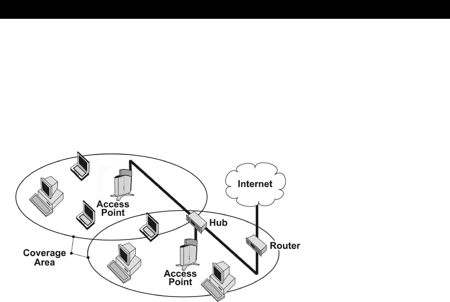
Wireless Networking Concepts
The AP-600 extends the capability of an existing Ethernet network to devices on a wireless network. Wireless devices
can connect to a single Access Point, or they can move between multiple Access Points located within the same
vicinity. As wireless clients move from one coverage cell to another, they maintain network connectivity.
To determine the best location for an Access Point, Proxim recommends conducting a Site Survey before placing the
device in its final location. For information about how to conduct a Site Survey, contact your local reseller.
Before an Access Point can be configured for your specific networking requirements, it must first be initialized. See
Installation & Basic Configuration for details.
Figure 1-1 Typical wireless network access infrastructure
Once initialized, the network administrator can configure each unit according to the network’s requirements. The
AP-600 functions as a wireless network access point to data networks. An AP-600 network provides:
•Seamless client roaming
•Easy installation and operation
•Over-the-air encryption of data
•High speed network links
Guidelines for Roaming
•An AP-600 can only communicate with client devices that support its wireless standard. For example, an 802.11a
client cannot communicate with an AP-600b and an 802.11b client cannot communicate with an AP-600a. Note
that an ORiNOCO 802.11a/b ComboCard can communicate with both the AP-600a and the AP-600b.
•All Access Points must have the same Network Name to support client roaming.
•All workstations with an 802.11 client adapter installed must use either a Network Name of “any” or the same
Network Name as the Access Points that they will roam between. If an AP-600b has Closed System enabled, a
client must have the same Network Name as the Access Point to communicate (see Wireless (AP-600b)).
•All Access Points and clients must have the same security settings to communicate.
•The Access Points’ cells must overlap to ensure that there are no gaps in coverage and to ensure that the roaming
client will always have a connection available.
•The coverage area of an AP-600b is larger than the coverage area of an AP-600a. The AP-600b operates in the
2.4 GHz frequency band; the AP-600a operates in the 5 GHz band. Products that operate in the 2.4 GHz band
offer greater range than products that operate in the 5 GHz band.
•An AP-600a operates at faster data rates than the AP-600b. 802.11a products like the AP-600a operate at speeds
of up to 54 Mbits/sec (108 Mbits/sec in Turbo mode); 802.11b products like the AP-600b operate at speeds of up to
11 Mbits/sec.
•All Access Points in the same vicinity should use a unique, independent Channel. By default, the AP-600
automatically scans for available Channels during boot-up but you can also set the Channel manually (see
Interfaces for details).
•Access Points that use the same Channel should be installed as far away from each other as possible to reduce
potential interference.

Introduction
13
Management and Monitoring Capabilities
There are several management and monitoring interfaces available to the network administrator to configure and
manage an AP-600 on the network:
•HTTP Interface
•Command Line Interface
•SNMP Management
•Wireless Network Manager
HTTP Interface
The HTTP Interface (Web browser Interface) provides easy access to configuration settings and network statistics
from any computer on the network. You can access the HTTP Interface over your LAN (switch, hub, etc.), over the
Internet, or with a “crossover” Ethernet cable connected directly to your computer’s Ethernet Port.
Command Line Interface
The Command Line Interface (CLI) is a text-based configuration utility that supports a set of keyboard commands and
parameters to configure and manage an AP-600.
Users enter Command Statements, composed of CLI Commands and their associated parameters. Statements may
be issued from the keyboard for real time control, or from scripts that automate configuration.
For example, when downloading a file, administrators enter the download CLI Command along with IP Address, file
name, and file type parameters.
You access the CLI over a HyperTerminal serial connection or via Telnet. During initial configuration, you can use the
CLI over a serial port connection to configure an Access Point’s IP address. When accessing the CLI via Telnet, you
can communicate with the Access Point from over your LAN (switch, hub, etc.), from over the Internet, or with a
“crossover” Ethernet cable connected directly to your computer’s Ethernet Port.
See Command Line Interface (CLI) for more information on the CLI and for a list of CLI commands and parameters.
SNMP Management
In addition to the HTTP and the CLI interfaces, you can also manage and configure an AP-600 using the Simple
Network Management Protocol (SNMP). Note that this requires an SNMP manager program, like HP Openview or
Castlerock’s SNMPc.
The AP-600 supports several Management Information Base (MIB) files that describe the parameters that can be
viewed and/or configured over SNMP:
–MIB-II (RFC 1213)
–Bridge MIB (RFC 1493)
–Ethernet-like MIB (RFC 1643)
–802.11 MIB
–ORiNOCO Enterprise MIB
Proxim provides these MIB files on the CD included with each Access Point. You need to compile one or more of the
above MIBs into your SNMP program’s database before you can manage an Access Point using SNMP. Refer to the
documentation that came with your SNMP manager for instructions on how to compile MIBs.
The Enterprise MIB defines the read and read-write objects that can be viewed or configured using SNMP. These
objects correspond to most of the settings and statistics that are available with the other management interfaces. Refer
to the Enterprise MIB for more information; the MIB can be opened with any text editor, such as Microsoft Word,
Notepad, or WordPad.
The remainder of this guide describes how to configure an AP-600 using the HTTP Web interface or the CLI
interface. For information on how to manage devices using SNMP, refer to the documentation that came with
your SNMP program. Also, refer to the MIB files for information on the parameters available via SNMP.

Introduction
14
Wireless Network Manager
The Wireless Network Manager is Proxim’s premier management tool for Access Points and Outdoor Routers. It
provides a single management interface that lets an IT manager configure, manage, upgrade, and troubleshoot
thousands of wireless devices from anywhere in the world. The Wireless Network Manager simplifies network
maintenance and easily integrates in an existing SNMP management system.
See Proxim’s Web site at http://www.proxim.com for more information on the Wireless Network Manager.
Active Ethernet
The AP-600 is equipped with an 802.3af-compliant Active Ethernet module. Active Ethernet (AE) delivers both data
and power to the access point over a single Ethernet cable. If you choose to use Active Ethernet, there is no difference
in operation; the only difference is in the power source.
–The Active Ethernet (AE) integrated module receives ~48 VDC over a standard Category 5 Ethernet cable.
–To use Active Ethernet, you must have an AE hub (also known as a power injector) connected to the network.
–The cable length between the AE hub and the Access Point should not exceed 100 meters (approximately
325 feet).
–The AE hub is not a repeater and does not amplify the Ethernet data signal.
–If connected to an AE hub and an AC power simultaneously, the Access Point draws power from Active
Ethernet.
–Maximum power supplied to an Access Point is 11 Watts; the unit typically draws approximately 10 Watts.
Also see Electrical Specifications.
The AP-600’s 802.3af-compliant Active Ethernet module is backwards compatible with all ORiNOCO Active
Ethernet hubs that do not support the IEEE 802.3af standard.

Introduction
15
Software Features
The table below compares the software features available for the AP-600a and the AP-600b:
*This feature is not available if you are using an ORiNOCO 802.11a/b ComboCard or a non-ORiNOCO client with the AP-600b.
Feature AP-600a
802.11a
AP-600b
802.11b
Comments
Number of stations per Basic Service Set (BSS) up to 50 up to 250
HTTP Server Yes Yes
Telnet / CLI Yes Yes
SNMP Agent Yes Yes
Emergency Reset to Default Configuration Yes Yes
DHCP Client Yes Yes
DHCP Server Yes Yes
TFTP Yes Yes
RADIUS Access Control Yes Yes
Fallback to Primary RADIUS Server Yes Yes
RADIUS Session Timeout Yes Yes
RADIUS Multiple MAC Address Formats Yes Yes
RADIUS DNS Host Name Support Yes Yes
RADIUS Start/Stop Accounting Yes Yes
802.1x Yes Yes
802.1d bridging Yes Yes
MAC Access Control Table Yes Yes
Protocol Filtering Yes Yes
Multicast/Broadcast Storm Filtering Yes Yes
Proxy ARP Yes Yes
ICMP Echo Response Yes Yes
Hardware Watchdog Timer Yes Yes
Roaming Yes Yes
Link Integrity Yes Yes
Automatic Channel Select Yes Yes
WEP Yes Yes Key lengths supported by AP-600b:
64-bit and 128-bit
Key lengths supported by AP-600a:
64-bit, 128-bit, and 152-bit
WEP Plus (Weak Key Avoidance) No Yes Available only one way (AP to client) if
using an
ORiNOCO 802.11a/b ComboCard or a
non-ORiNOCO client.
WDS Relay No Yes
Remote Link Test No Yes
Link Test Responder No Yes*
Medium Density Distribution No Yes*
Distance between APs No Yes*
Ultra High Density No Yes*
Closed System No Yes
Interference Robustness No Yes
Load Balancing No Yes*
SpectraLink VoIP Support No Yes
Fragmentation Yes Yes For AP-600b, Fragmentation is
implemented as part of the Interference
Robustness feature.
Blocking Intra BSS Clients Yes Yes
Packet Forwarding Yes Yes
TCP/UDP Port Filtering Yes Yes
Dynamic Frequency Selection (DFS) Yes No DFS is required for 802.11a products
sold in Europe
Per User Per Session Encryption Yes No Use in conjunction with 802.1x
Syslog Messaging Yes Yes
2X Turbo Mode Yes No Not available in all countries

Introduction
16
The following table provides detailed information on the some of the differences between the 802.11a and 802.11b
feature sets.
AP-600a
(802.11a)
AP-600b
(802.11b)
Physical Layer Type
(Modulation Type)
ODFM
(Orthogonal Frequency Division Multiplexing)
DSSS
(Direct Sequence Spread Spectrum)
Auto Channel Select Enable (default)
Disable
Note: A user cannot manually select a
channel for products sold in Europe; these
products require automatic channel selection
using DFS. See Dynamic Frequency
Selection (DFS).
Enable (default)
Disable
Frequency Channel Available Channels vary by regulatory domain
and/or country. See 802.11a Channel
Frequencies for the AP-600a for details.
Available Channels vary by regulatory domain
and/or country. See 802.11b Channel
Frequencies for the AP-600b for details.
Transmit Rate 0 - Auto Fallback (default)
6 Mbits/sec
9 Mbits/sec
12 Mbits/sec
18 Mbits/sec
24 Mbits/sec
36 Mbits/sec
48 Mbits/sec
54 Mbits/sec
For 2X Turbo mode (not available in all
countries):
0 - Auto Fallback (default)
12 Mbits/sec
18 Mbits/sec
24 Mbits/sec
36 Mbits/sec
48 Mbits/sec
72 Mbits/sec
96 Mbits/sec
108 Mbits/sec
N/A
Distance Between APs N/A Large (default)
Medium
Small
Minicell
Microcell
Multicast Rate N/A 1 Mbits/sec
2 Mbits/sec
5.5 Mbits/sec
11 Mbits/sec
Available options depend on Distance
Between APs setting
Interference Robustness N/A Enable (default)
Disable
Closed System N/A Enable
Disable (default)
Load Balancing N/A Enable (default)
Disable
Medium Density Distribution N/A Enable (default)
Disable
17
2
Installation & Basic Configuration
In This Chapter
This chapter describes how to install and configure an AP-600 for the first time.
•Prerequisites
•Installation
•Initialization
•Download the Latest Software
•Additional Hardware Features
Prerequisites
Before installing an AP-600, you need to gather certain network information. The following section identifies the
information you need.
Network Name (SSID of the wireless cards) You must assign the Access Point a Network Name before wireless users can
communicate with it. The clients also need the same Network Name. This is not the same
as the System Name, which applies only to the Access Point. The network administrator
typically provides the Network Name.
AP-600’s IP Address If you do not have a DHCP server on your network, then you need to assign the
Access Point an IP address that is valid on your network.
HTTP Password Each Access Point requires a read/write password to access the web interface. The default
password is “public”.
CLI Password Each Access Point requires a read/write password to access the CLI interface. The default
password is “public”.
SNMP Read Password Each Access Point requires a password to allow get requests from an SNMP manager. The
default password is “public”.
SNMP Read-Write Password Each Access Point requires a password to allow get and set requests from an SNMP
manager. The default password is “public”.
Security Settings You need to determine what security features you will enable on the Access Point.
Authentication Method A primary authentication server may be configured; a backup authentication server is
optional. The network administrator typically provides this information.
Authentication Server Shared Secret This is a password shared between the Access Point and the RADIUS authentication
server (so both passwords must be the same), and is typically provided by the network
administrator.
Authentication Server Authentication Port This is a port number (default is 1812) and is typically provided by the network
administrator.
Client IP Address Pool Allocation Scheme The Access Point can automatically provide IP addresses to clients as they sign on. The
network administrator typically provides the IP Pool range.
DNS Server IP Address The network administrator typically provides this IP Address.
Installation & Basic Configuration
18
Installation
Follow these steps to install an AP-600:
1. Unpack the Access Point and accessories from the shipping box.
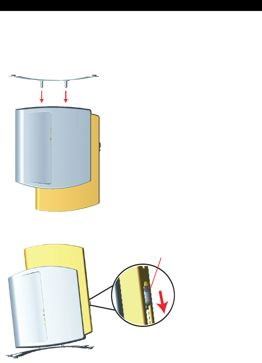
2. If you intend to install the unit free-standing or if you intend to mount it to the ceiling, use a Phillips screwdriver to
attach the metal base to the underside of the unit. The metal base and screws are provided. See Mounting Options
for additional information.
Figure 2-1 Attach the Metal Base
3. Press down on the cable-cover lock located in the front-center of the unit to release the cable cover.
Figure 2-2 Unlock the Cable Cover
4. Remove the cable cover from the unit.
cable-cover lock
Installation & Basic Configuration
19
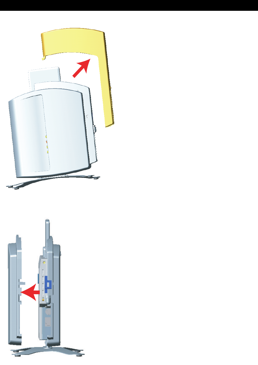
Figure 2-3 Remove Cable Cover
5. Remove the front cover (the side with the LED indicators) from the unit.
Figure 2-4 Remove the Front Cover
6. Remove the back cover from the unit.
Installation & Basic Configuration
20
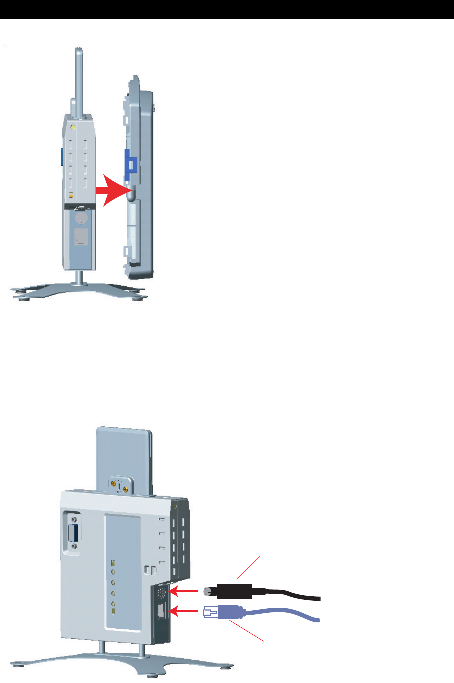
Figure 2-5 Remove the Back Cover
7. Connect one end of an Ethernet cable to the Access Point’s Ethernet port. The other end of the cable should not
be connected to another device until after the installation is complete.
•Use a straight-through Ethernet cable if you intend to connect the Access Point to a hub, switch, patch panel,
or Active Ethernet power injector.
•Use a cross-over Ethernet cable if you intend to connect the Access Point to a single computer.
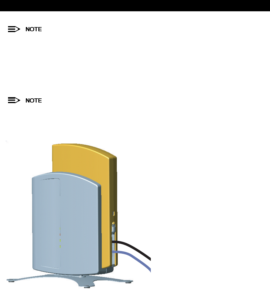
8. If you are not using Active Ethernet (or you want to connect the Access Point to Active Ethernet and AC power
simultaneously), attach the AC power cable to the Access Point’s power port.
Figure 2-6 Attach Ethernet Cable and Power Cable
Ethernet Cable
Power Cable
Installation & Basic Configuration
21
Once attached, the power cable locks into place. To disconnect the power cable, slide back the black plastic
fitting and gently pull the cable from the connector.
9. Connect the free end of the Ethernet cable to a hub, switch, patch panel, Active Ethernet power injector, or an
Ethernet port on a computer.
10. If using AC power, connect the power cord to a power source (such as a wall outlet) to turn on the unit.
11. Configure and test the unit. See Initialization for details.
12. Download the latest software to the unit, if necessary. See Download the Latest Software for details.
13. Place the unit in the final installation location. See Mounting Options for mounting options and instructions.
Proxim recommends that you perform a Site Survey prior to determine the installation location for your AP-600
units. For information about how to conduct a Site Survey, contact your local reseller.
14. Replace the back cover, front cover, and cable cover. Be careful to avoid trapping the power and Ethernet cables
when replacing the cable cover.
Figure 2-7 Assembled Unit
15. If desired, you can attach a Kensington lock to secure the cable cover into place. This will protect the unit from
unauthorized tampering. See Kensington Security Slot for details.

Installation & Basic Configuration
22
Initialization
Proxim provides two tools to simplify the initialization and configuration of an AP-600:
•ScanTool
•Setup Wizard
ScanTool is included on the ORiNOCO CD; the Setup Wizard launches automatically the first time you access the
HTTP interface.
These initialization instructions describe how to configure an AP-600 over an Ethernet connection using
ScanTool and the HTTP interface. If you want to configure the unit over the serial port, see Setting IP Address
using Serial Port and Normal CLI for information on how to access the CLI over a serial connection and
Command Line Interface (CLI) for a list of supported commands.
ScanTool
ScanTool is a software utility that is included on the installation CD-ROM. The tool automatically detects the
Access Points installed on your network, regardless of IP address, and lets you configure each unit’s IP settings. In
addition, you can use ScanTool to download new software to an AP-600 that does not have a valid software image
installed (see Client Connection Problems).
To access the HTTP interface and configure the AP-600, the AP-600 must be assigned an IP address that is valid on
its Ethernet network. By default, the AP-600 is configured to obtain an IP address automatically from a network
Dynamic Host Configuration Protocol (DHCP) server during boot-up. If your network contains a DHCP server, you can
run ScanTool to find out what IP address the AP-600 has been assigned. If your network does not contain a DHCP
server, the Access Point’s IP address defaults to 169.254.128.132. In this case, you can use ScanTool to assign the
AP-600 a static IP address that is valid on your network.
ScanTool Instructions
Follow these steps to install ScanTool, initialize the Access Point, and perform initial configuration:
1. Locate the unit’s Ethernet MAC address and write it down for future reference. The MAC address is printed on the
product label. Each unit has a unique MAC address, which is assigned at the factory.
2. Confirm that the AP-600 is connected to the same LAN subnet as the computer that you will use to configure the
AP-600.
3. Power up, reboot, or reset the AP-600.
–Result: The unit requests an IP Address from the network DHCP server.
4. Insert the ORiNOCO CD into the CD-ROM drive of the computer that you will use to configure the AP-600.
–Result: The installation program will launch automatically.
5. Follow the on-screen instructions to install the Access Point software and documentation.
The ORiNOCO Installation program supports the following operating systems:
•Windows 98
•Windows 2000
•Windows ME
•Windows XP
6. After the software has been installed, double-click the ScanTool icon on the Windows desktop to launch the
program.
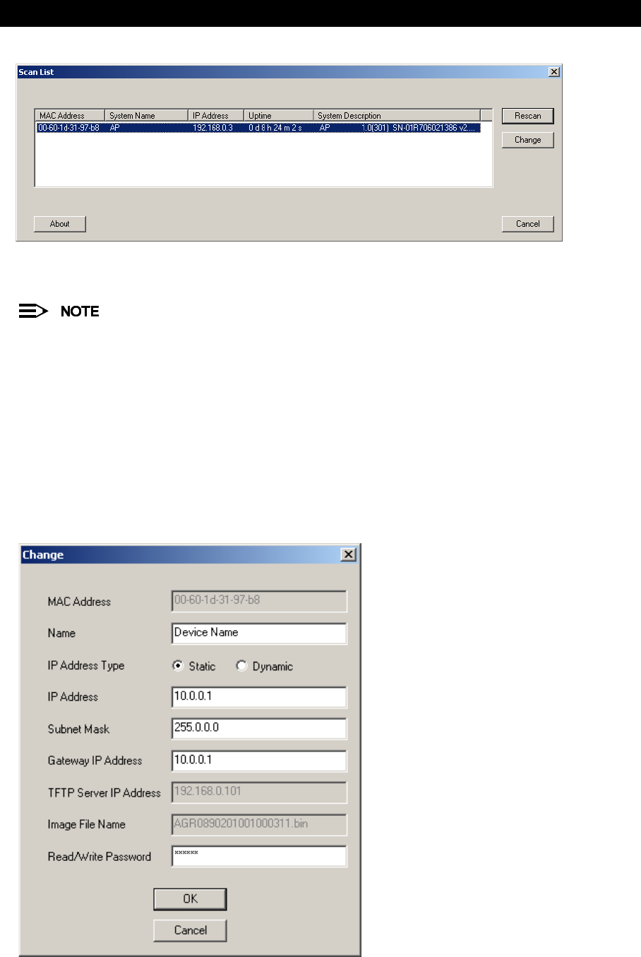
–Result: ScanTool scans the subnet and displays all detected ORiNOCO Access Points. The ScanTool’s
Scan
List
screen appears, as shown in the following example.
Installation & Basic Configuration
23
Figure 2-8 Scan List
7. Locate the MAC address of the AP-600 you want to initialize within the Scan List.
If your Access Point does not show up in the Scan List, click the Rescan button to update the display. If the
unit still does not appear in the list, see Troubleshooting for suggestions. Note that after rebooting an
Access Point, it may take up to five minutes for the unit to appear in the Scan List.
8. Do one of the following:
•If the AP-600 has been assigned an IP address by a DHCP server on the network, write down the IP address
and click Cancel to close ScanTool. Proceed to Setup Wizard for information on how to access the HTTP
interface using this IP address.
•If the AP-600 has not been assigned an IP address (in other words, the unit is using its default IP address,
169.254.128.132), follow these steps to assign it a static IP address that is valid on your network:
1. Highlight the entry for the AP-600 you want to configure.
2. Click the Change button.
—Result: the
Change
screen appears.
Figure 2-9 Scan Tool Change Screen

Installation & Basic Configuration
24
3. Set IP Address Type to Static.
4. Enter a static IP Address for the AP-600 in the field provided. You must assign the unit a unique address
that is valid on your IP subnet. Contact your network administrator if you need assistance selecting an IP
address for the unit.
5. Enter your network’s Subnet Mask in the field provided.
6. Enter your network’s Gateway IP Address in the field provided.
7. Enter the SNMP Read/Write password in the Read/Write Password field (for new units, the default
SNMP Read/Write password is “public”).
The TFTP Server IP Address and Image File Name fields are only available if ScanTool detects that the
AP-600 does not have a valid software image installed. See Client Connection Problems.
8. Click OK to save your changes.
—Result: The Access Point will reboot automatically and any changes you made will take effect.
9. When prompted, click OK a second time to return to the
Scan List
screen.
10. Click Cancel to close the ScanTool.
11. Proceed to Setup Wizard for information on how to access the HTTP interface.
Setup Wizard
The first time you connect to an AP-600’s HTTP interface, the Setup Wizard launches automatically. The Setup Wizard
provides step-by-step instructions for how to configure the Access Point’s basic operating parameter, such as Network
Name, IP parameters, system parameters, and management passwords.
Setup Wizard Instructions
Follow these steps to access the Access Point’s HTTP interface and launch the Setup Wizard:
1. Open a Web browser on a network computer.
The HTTP interface supports the following Web browser:
•Microsoft Internet Explorer 5.5 or later
•Netscape 4.x or later
2. If necessary, disable the browser’s Internet proxy settings. For Internet Explorer users, follow these steps:
–Select Tools > Internet Options....
–Click the Connections tab.
–Click LAN Settings....
–If necessary, remove the check mark from the Use a proxy server box.
–Click OK twice to save your changes and return to Internet Explorer.
3. Enter the Access Point’s IP address in the browser’s Address field and press Enter.
–This is either the dynamic IP address assigned by a network DHCP server or the static IP address you
manually configured. See ScanTool for information on how to determine the unit’s IP address and manually
configure a new IP address, if necessary.
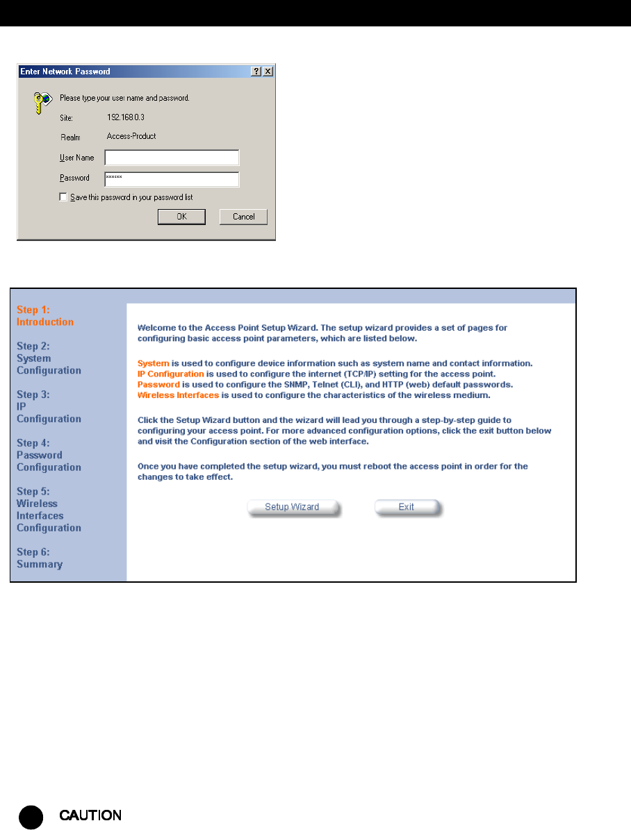
–Result: The
Enter Network Password
screen appears.
4. Enter the HTTP password in the Password field. Leave the User Name field blank. For new units, the default
HTTP password is “public”.
–Result: The Setup Wizard will launch automatically.
Installation & Basic Configuration
25
Figure 2-10 Enter Network Password
Figure 2-11 Setup Wizard
5. Click Setup Wizard to begin. If you want to configure the AP-600 without using the Setup Wizard, click Exit and
see Advanced Configuration.
The Setup Wizard supports the following navigation options:
•Save & Next Button: Each Setup Wizard screen has a Save & Next button. Click this button to submit any
changes you made to the unit’s parameters and continue to the next page. The instructions below describe
how to navigate the Setup Wizard using the Save & Next buttons.
•Navigation Panel: The Setup Wizard provides a navigation panel on the left-hand side of the screen. Click
the link that corresponds to the parameters you want to configure to be taken to that particular configuration
screen. Note that clicking a link in the navigation panel will not submit any changes you made to the unit’s
configuration on the current page.
•Exit: The navigation panel also includes an Exit option. Click this link to close the Setup Wizard at any time.
!
If you exit from the Setup Wizard, any changes you submitted (by clicking the Save & Next button) up to that
point will be saved to the unit but will not take effect until it is rebooted.
6. Configure the System Configuration settings and click Save & Next. See System for more information.
7. Configure the Access Point’s Basic IP address settings, if necessary, and click Save & Next. See Basic IP
Parameters for more information.

Installation & Basic Configuration
26
8. Assign the AP-600 new passwords to prevent unauthorized access and click Save & Next. Each management
interface has its own password:
—SNMP Read Password
—SNMP Read-Write Password
—CLI Password
—HTTP (Web) Password
By default, each of these passwords is set to “public”. See Passwords for more information.
9. Configure the basic wireless interface settings and click Save & Next.
•The following options are available for the AP-600a:
—Network Name (SSID): Enter a Network Name (between 2 and 31 characters long) for the wireless
network. You must configure each wireless client to use this name as well.
—Auto Channel Select: By default, the AP-600a scans the area for other Access Points and selects a free
or relatively unused communication channel. This helps prevent interference problems and increases
network performance. Remove the check mark to disable this option. Note that you cannot disable Auto
Channel Select for 802.11a products in Europe (see Dynamic Frequency Selection (DFS) for details).
—Frequency Channel: When Auto Channel Select is enabled, this field is read-only and displays the
Access Point’s current operating channel. When Auto Channel Select is disabled, you can specify the
Access Point’s channel. If you decide to manually set the unit’s channel, ensure that nearby devices do
not use the same frequency. Available Channels vary based on regulatory domain. See 802.11a Channel
Frequencies for the AP-600a. Note that you cannot manually set the channel for 802.11a products in
Europe (see Dynamic Frequency Selection (DFS) for details).
—Transmit Rate: Use the drop-down menu to select a specific transmit rate for the AP-600a. Choose
between 6, 9, 12, 18, 24, 36, 48, 54 Mbits/s, and Auto Fallback. The Auto Fallback feature allows the
AP-600a unit to select the best transmit rate based on the cell size.
—WEP Encryption: Place a check mark in the box provided to enable WEP encryption. See WEP
Encryption for more information.
—Set Encryption Key 1: If you enabled Encryption, configure an Encryption Key. This key is used to
encrypt and decrypt data between the AP-600a and its wireless clients. Enter the number of characters
that correspond to the desired key size, as described below:
—Enter 10 hexadecimal characters (0-9 and A-F) or 5 ASCII characters (see ASCII Character Chart) to
use 64-bit encryption.
—Enter 26 hexadecimal characters or 13 ASCII characters to use 128-bit encryption.
—Enter 32 hexadecimal characters or 16 ASCII characters to use 152-bit encryption.
•The following options are available for the AP-600b:
—Network Name (SSID): Enter a Network Name (between 2 and 31 characters long) for the wireless
network. You must configure each wireless client to use this name as well.
—Auto Channel Select: The AP-600b scans the area for other Access Points and selects a free or
relatively unused communication channel. This helps prevent interference problems and increases
network performance. Remove the check mark to disable this option. If you are setting up a Wireless
Distribution System (WDS), it must be disabled. See Wireless Distribution System (WDS) for more
information.
—Frequency Channel: When Auto Channel Select is enabled, this field is read-only and displays the
Access Point’s current operating channel. When Auto Channel Select is disabled, you can specify the
Access Point’s operating channel. If you decide to manually set the unit’s channel, ensure that nearby
devices do not use the same frequency (unless you are setting up a WDS). Available Channels vary
based on regulatory domain. See 802.11b Channel Frequencies for the AP-600b.
—Distance Between APs: Set to Large, Medium, Small, Microcell, or Minicell depending on the site
survey for your system. The distance value is related to the Multicast Rate (described next). In general, a
larger distance between APs means that your clients operate a slower data rates (on average). See
Distance Between APs for more information.

Installation & Basic Configuration
27
—Multicast Rate: Sets the rate at which Multicast messages are sent. This value is related to the Distance
Between APs parameter (described previously). The table below displays the possible Multicast Rates
based on the Distance between APs. See Multicast Rate for more information.
—WEP Encryption: Place a check mark in the box provided to enable WEP encryption. See WEP
Encryption for more information.
—Set Encryption Key 1: If you enabled Encryption, configure an Encryption Key. This key is used to
encrypt and decrypt data between the AP-600a and its wireless clients. Enter the number of characters
that correspond to the desired key size, as described below:
—Enter 10 hexadecimal characters (0-9 and A-F) or 5 ASCII characters (see ASCII Character Chart) to
use 64-bit encryption.
—Enter 26 hexadecimal characters (0-9 and A-F) or 13 ASCII characters to use 128-bit encryption.
Additional advanced settings are available in the
Wireless Interface Configuration
screen. See Wireless
(AP-600a) or Wireless (AP-600b) for details. See Security for more information on security features.
10. Review the configuration summary. If you want to make any additional changes, use the navigation panel on the
left-hand side of the screen to return to an earlier screen. After making a change, click Save & Next to save the
change and proceed to the next screen.
11. When finished, click Reboot on the Summary screen to restart the AP-600 and apply your changes.
Download the Latest Software
Proxim periodically releases updated software for the AP-600 on its Web site at http://www.proxim.com/support/.
Proxim recommends that you check the Web site for the latest updates after you have installed and initialized the unit.
Three types of files can be downloaded to the AP-600 from a TFTP server:
—Img (AP software image or kernel)
—Config (configuration file)
—bspBl (BSP/Bootloader firmware file)
Setup your TFTP Server
A Trivial File Transfer Protocol (TFTP) server allows you to transfer files across a network. You can upload files from
the AP-600 for backup or copying, and you can download the files for configuration and AP Image upgrades. The
Solarwinds TFTP server software is located on the ORiNOCO AP-600 Installation CD-ROM. You can also download
the latest TFTP software from Solarwind’s Web site at http://www.solarwinds.net.
If a TFTP server is not configured and running, you will not be able to download and upload images and configuration
files to/from the AP-600. Remember that the TFTP server does not have to be local as long as you have a valid TFTP
IP address. Also, a TFTP server does not have to be running for the AP-600 to perform tasks that do not involve file
transfers.
After the TFTP server is installed:
•Check to see that TFTP is configured to point to the directory containing the AP Image.
•Make sure you have the proper TFTP server IP address, the proper AP Image file name, and that the TFTP server
is operational.
•
-
Distance between APs Multicast Rate
Large 1 and 2 Mbits/sec
Medium 1, 2, and 5.5 Mbits/sec
Small 1, 2, 5.5 and 11 Mbits/sec
Minicell 1, 2, 5.5 and 11 Mbits/sec
Microcell 1, 2, 5.5 and 11 Mbits/sec

Installation & Basic Configuration
28
Download Updates from your TFTP Server using the Web Interface
1. Download the latest software from http://www.proxim.com/support/.
2. Copy the latest software updates to your TFTP server.
3. In the Web Interface, click the Commands button and select the Download tab.
4. Enter the IP address of your TFTP server in the field provided.
5. Enter the File Name (including the file extension). Enter the full directory path and file name. If the file is located in
the default TFTP directory, you need enter only the file name.
6. Select the File Type from the drop-down menu (use
Img
for software updates).
7. Select Download & Reboot from the File Operation drop-down menu.
8. Click OK.
9. The Access Point will reboot automatically when the download is complete.
Download Updates from your TFTP Server using the CLI Interface
1. Download the latest software from http://www.proxim.com/support/.
2. Copy the latest software updates to your TFTP server.
3. Open the CLI interface via Telnet or a serial connection.
4. Enter the CLI password when prompted.
5. Type set tftpfilename <file name> (include the file extension) and press Enter.
6. Type set tftpfiletype img and press Enter.
7. Type set tftpipaddr <IP address of your TFTP server> and press Enter.
8. Type show tftp and confirm that the file name, file type, and IP address are correct.
9. Type download * and press Enter.
–Result: The download will begin. Be patient while the image is downloaded to the Access Point.
10. When the download is complete, type reboot 0 and press Enter.
See Command Line Interface (CLI) for more information.
Additional Hardware Features
•Mounting Options
•Kensington Security Slot
•LED Indicators
Mounting Options
There are three mounting options for the AP-600, described below.
Desktop Mount
This is the standard installation for the AP-600. See Installation for instructions.
Wall Mount
Follow these steps to mount the AP-600 on a wall:
1. Identify the location where you intend to mount the unit.
For best results, mount the unit vertically. In other words, the antenna should be pointing up or down but not
sideways.
2. Unplug the Access Point’s power supply, if necessary.
3. Use a Phillips screwdriver to remove the metal base from the underside of the AP-600, if necessary.
4. Press down on the cable cover lock to release the cable cover. See Unlock the Cable Cover for an illustration.
5. Remove the cable cover from the unit. See Remove Cable Cover for an illustration.
6. Remove the front cover from the unit. See Remove the Front Cover for an illustration.
Installation & Basic Configuration
29
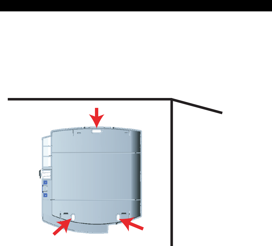
7. Remove the back cover from the unit. See Remove the Back Cover for an illustration.
8. Place the back cover on the mounting location and mark the center of the three mounting holes.
9. Remove the cover from the wall and drill a hole at each of the locations you marked above. Each hole should be
wide enough to hold a mounting plug (which is 6 mm x 35 mm).
10. Insert a plug into each hole. The AP-600 comes with four 6 mm x 35 mm plugs; you only need to use three of these
when wall mounting the unit.
11. Insert a screw into each of the mounting holes molded into the back cover. The AP-600 comes with four 3.5 mm x
40 mm pan-head screws; you only need to use three of these when wall mounting the unit.
12. Insert the screws into the wall plugs. Use a screwdriver to tighten the screws and attach the back cover to the wall.
In the following example, the back cover is mounted upside down (the two holes are at the bottom).
Figure 2-12 Attach the Back Cover to the Wall
13. Attach Ethernet and power cables to the AP-600 unit, if necessary.
14. Snap the unit into the back cover. In the following example, the unit is mounted upside down and its antenna is
facing down.
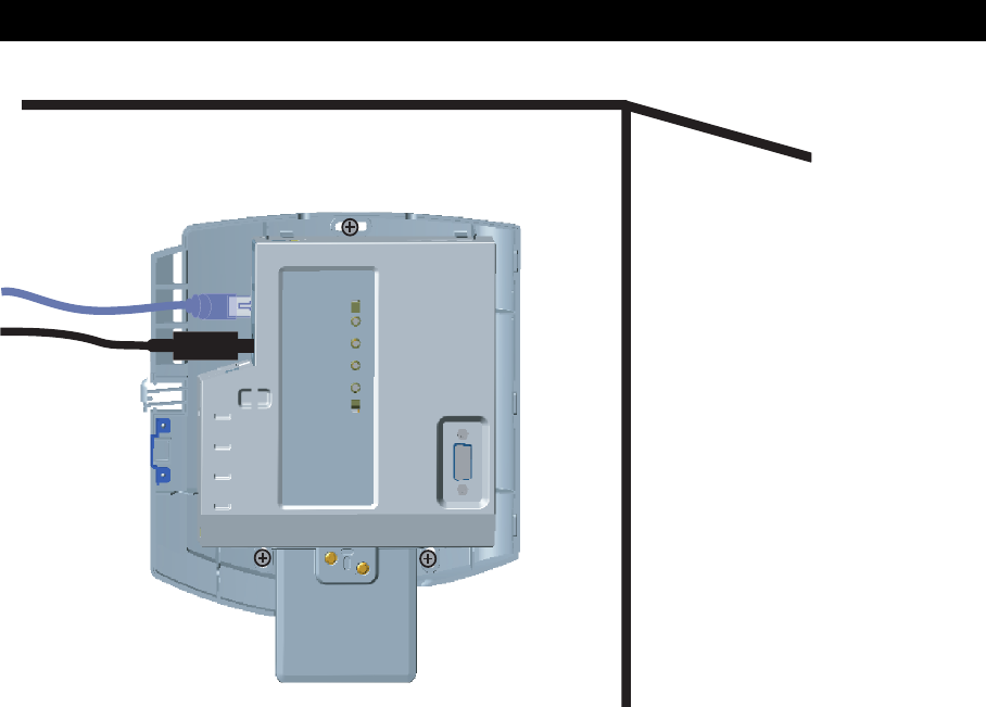
Installation & Basic Configuration
30
Figure 2-13 AP-600 Mounted on a Wall
15. Replace the front cover.
16. Replace the cable cover.
17. Turn on the AP-600.
Ceiling Mount
Follow these steps to mount the AP-600 to a ceiling:
1. Unplug the Access Point’s power supply, if necessary.
2. Use a Phillips screwdriver to attach the metal base to the underside of the AP-600, if necessary. See Attach the
Metal Base for an illustration.
3. Feed a mounting screw through each of the four rubber feet. The AP-600 comes with four 3.5 mm x 40 mm
pan-head screws.
4. Remove the screws from the rubber feet.
5. Turn the AP-600 upside down position the base against the ceiling where you want to mount the unit.
6. Mark the center of the four mounting holes in the rubber feet.
7. Set the AP-600 aside and drill a hole at each of the locations you marked above. Each hole should be wide enough
to hold a mounting plug (which is 6 mm x 35 mm).
8. Insert a plug into each hole. The AP-600 comes with four 6 mm x 35 mm plugs.
9. Insert the screws into the holes you made previously in the rubber feet.
10. Insert the screws into the wall plugs. Use a screwdriver to tighten the screws and attach the Access Point’s metal
base to the ceiling.
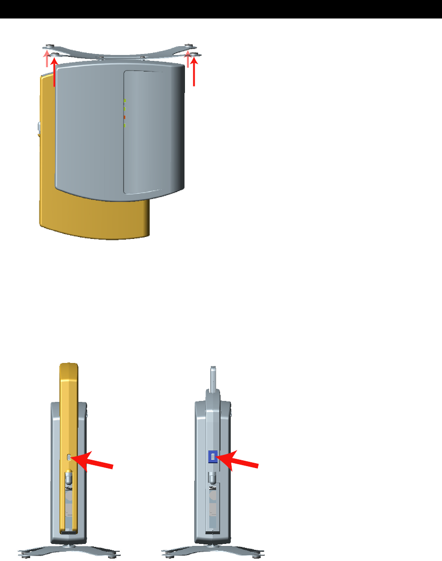
Installation & Basic Configuration
31
Figure 2-14 Mounting the AP-600 to the Ceiling
Kensington Security Slot
The AP-600 enclosure includes a Kensington Security Slot for use with a Kensington locking mechanism. When
properly installed, a Kensington lock can prevent unauthorized personnel from stealing the AP-600. In addition, the
Kensington locks secures the cable cover in place, which prevents tampering with the Ethernet and power cables.
The Kensington Security Slot is shown in the illustrations below (the figure on the left shows the slot with the cable
cover attached; the figure on the right shows the slot with the cable cover removed). See http://www.kensington.com
for information on Kensington security solutions.
Figure 2-15 Kensington Security Slot
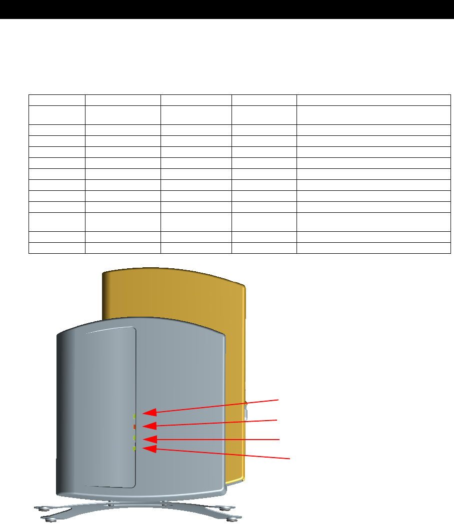
Installation & Basic Configuration
32
LED Indicators
The AP-600 has four LED indicators. The LEDs are identified in LED Indicators Illustrated and exhibit the following
behavior:
Figure 2-16 LED Indicators Illustrated
Related Topics
The Setup Wizard helps you configure the basic AP-600 settings required to get the unit up and running. The AP-600
supports many other configuration and management options. The remainder of this user guide describes these options
in detail.
–See Advanced Configuration for information on configuration options that are available within the Access Point’s
HTTP interface.
–See Monitor Information for information on the statistics displayed within the Access Point’s HTTP interface.
–See Commands for information on the commands supported by the Access Point’s HTTP interface.
–See Troubleshooting for troubleshooting suggestions.
–See Command Line Interface (CLI) for information on the CLI interface and for a list of CLI commands.
Power Ethernet Link Ethernet Activity Wireless Activity Indication
Solid Green Green when link
exists
Green flash
with data activity
Green flash
with data activity
Normal Operation
Solid Amber Solid Amber Solid Amber Solid Amber Rebooting
Solid Green Solid Amber Solid Amber Solid Amber Reset to Factory Defaults command issued
Solid Red Off Off Off SDRAM Test Failure
Blinking Red Blinking Red or Off Blinking Red Off Hardware Timer Test Failure
Blinking Red Off Off Blinking Red Flash Test Failure
Solid Red Blinking Red or Off Solid Red Off Ethernet Test Failure
Solid Red Off Off Solid Red Wireless Test Failure
Blinking Amber Blinking Amber or Off Blinking Amber or Off Off Missing or bad AP image
Solid Amber Solid Amber Solid Amber Solid Amber Missing or bad bootloader image (all LEDs
remain solid amber)
n/a n/a n/a Red Wireless radio is not working properly
n/a n/a Amber Amber Indicated interface in administrative down state
Power LED
Wireless Activity LED
Ethernet Activity LED
Ethernet Link LED
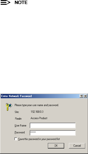
33
3
Status Information
In This Chapter
This chapter describes the statistical information that is reported within the Access Point’s HTTP interface.
•Logging into the HTTP Interface
•System Status
Logging into the HTTP Interface
Once the AP-600 has a valid IP Address and an Ethernet connection, you may use your web browser to monitor the
system status.
Follow these steps to monitor an AP-600’s operating statistics using the HTTP interface:
1. Open a Web browser on a network computer.
The HTTP interface supports the following Web browser:
•Microsoft Internet Explorer 5.5 or later
•Netscape 4.x or later
2. If necessary, disable the Internet proxy settings. For Internet Explorer users, follow these steps:
–Select Tools > Internet Options....
–Click the Connections tab.
–Click LAN Settings....
–If necessary, remove the check mark from the Use a proxy server box.
–Click OK twice to save your changes and return to Internet Explorer.
3. Enter the Access Point’s IP address in the browser’s Address field and press Enter.
–Result: The
Enter Network Password
screen appears.
4. Enter the HTTP password in the Password field and click OK. Leave the User Name field blank. (By default, the
HTTP password is “public”).
–Result: The
System Status
screen appears.
Figure 3-1 Enter Network Password Screen
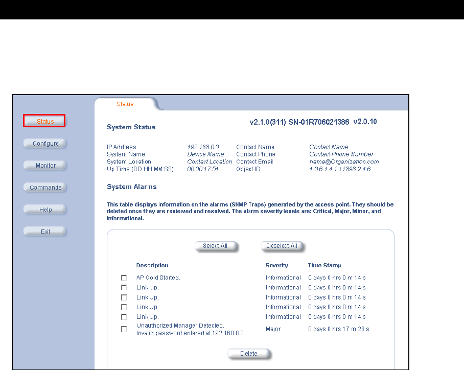
Status Information
34
System Status
System Status
is the first screen to appear each time you connect to the HTTP interface. You can also return to this
screen by clicking the Status button.
Figure 3-2 System Status Screen
Each section of the
System Status
screen provides the following information:
–System Status: This area provides system level information, including the unit’s IP address and contact
information. See System for information on these settings.
–System Alarms: System traps (if any) appear in this area. Each trap identifies a specific severity level:
Critical, Major, Minor, and Informational. See System Alarms (Traps) for a list of possible alarms.

35
4
Advanced Configuration
In This Chapter
This chapter describes all of the operating parameters that can be configured using the Access Point’s HTTP interface.
•Configuring the AP-600 Using the HTTP Interface
•System: Configure specific system information such as system name and contact information.
•Network: Configure IP settings, DNS client, DHCP server, and Link Integrity.
•Interfaces: Configure the Access Point’s interfaces: Wireless and Ethernet.
•Management: Configure the Access Point’s management Passwords, IP Access Table, and Services.
•Filtering: Configure Ethernet Protocol filters, Static MAC Address filters, Advanced filters, and Port filters.
•Alarms: Configure the Alarm (SNMP Trap) Groups, the Alarm Host Table, and the Syslog features.
•Bridge: Configure the Spanning Tree Protocol, Storm Threshold protection, Intra BSS traffic, and Packet
Forwarding.
•Security: Configure security features such as MAC Access Control, WEP Encryption, and 802.1x.
•RADIUS: Configure RADIUS features such as RADIUS Access Control and Accounting.
Configuring the AP-600 Using the HTTP Interface
Follow these steps to configure an Access Point’s operating settings using the HTTP interface:
1. Open a Web browser on a network computer.
The HTTP interface supports the following Web browser:
•Microsoft Internet Explorer 5.5 or later
•Netscape 4.x or later
2. If necessary, disable the Internet proxy settings. For Internet Explorer users, follow these steps:
–Select Tools > Internet Options....
–Click the Connections tab.
–Click LAN Settings....
–If necessary, remove the check mark from the Use a proxy server box.
–Click OK twice to save your changes and return to Internet Explorer.
3. Enter the Access Point’s IP address in the browser’s Address field and press Enter.
–Result: The
Enter Network Password
screen appears.
4. Enter the HTTP password in the Password field and click OK. Leave the User Name field blank. (By default, the
HTTP password is “public”).
–Result: The
System Status
screen appears.
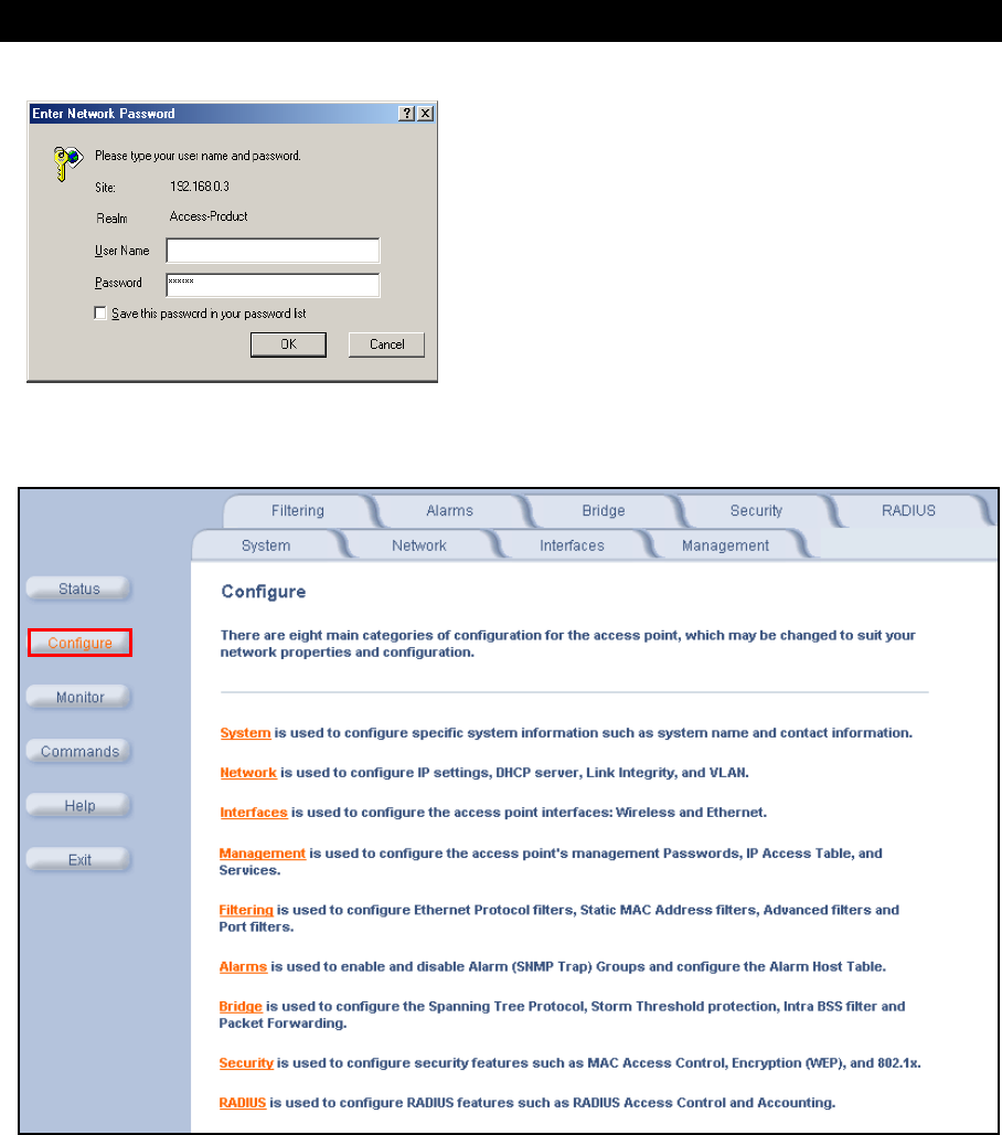
Advanced Configuration
36
Figure 4-1 Enter Network Password Screen
5. Click the Configure button located on the left-hand side of the screen.
Figure 4-2 Configure Main Screen
6. Click the tab that corresponds to the parameter you want to configure. For example, click Network to configure the
Access Point’s TCP/IP settings. The parameters contained in each of the nine configuration categories are
described later in this chapter.
7. Configure the Access Point’s parameters as necessary. After changing a configuration value, click OK to save the
change.
8. Reboot the Access Point for all of the changes to take effect.

Advanced Configuration
37
System
You can configure and view the following parameters within the
System Configuration
screen:
•Name: The name assigned to the AP-600.
•Location: The location where the AP-600 is installed.
•Contact Name: The name of the person responsible for the AP-600.
•Contact Email: The email address of the person responsible for the AP-600.
•Contact Phone: The telephone number of the person responsible for the AP-600.
•Object ID: This is a read-only field that displays the Access Point’s MIB definition; this information is useful if you
are managing the AP-600 using SNMP.
•Ethernet MAC Address: This is a read-only field that displays the unique MAC (Media Access Control) address
for the Access Point’s Ethernet interface. The MAC address is assigned at the factory.
•Descriptor: This is a read-only field that reports the Access Point’s name, serial number, current image software
version, and current bootloader software version.
•Up Time: This is a read-only field that displays how long the Access Point has been running since its last reboot.
Network
The Network category contains three sub-categories.
–IP Configuration
–DHCP Server
–Link Integrity
IP Configuration
You can configure and view the following parameters within the
IP Configuration
screen:
You must reboot the Access Point in order for any changes to the Basic IP or DNS Client parameters take
effect.
Basic IP Parameters
•IP Address Assignment Type: Set this parameter to Dynamic to configure the Access Point as a Dynamic Host
Configuration Protocol (DHCP) client; the Access Point will obtain IP settings from a network DHCP server
automatically during boot-up. If you do not have a DHCP server or if you want to manually configure the
Access Point’s IP settings, set this parameter to Static.
•IP Address: The Access Point’s IP address. When IP Address Assignment Type is set to Dynamic, this field is
read-only and reports the unit’s current IP address. The Access Point will default to 169.254.128.132 if it cannot
obtain an address from a DHCP server.
•Subnet Mask: The Access Point’s subnet mask. When IP Address Assignment Type is set to Dynamic, this field is
read-only and reports the unit’s current subnet mask. The subnet mask will default to 255.255.0.0 if the unit cannot
obtain one from a DHCP server.
•Gateway IP Address: The IP address of the Access Point’s gateway. When IP Address Assignment Type is set to
Dynamic, this field is read-only and reports the IP address of the unit’s gateway. The gateway IP address will
default to 169.254.128.133 if the unit cannot obtain an address from a DHCP server.
DNS Client
If you prefer to use host names to identify network servers rather than IP addresses, you can configure the AP-600 to
act as a Domain Name Service (DNS) client. When this feature is enabled, the Access Point contacts the network’s
DNS server to translate a host name to the appropriate network IP address. You can use this DNS Client functionality
to identify RADIUS servers by host name. See RADIUS for details.
•Enable DNS Client: Place a check mark in the box provided to enable DNS client functionality. Note that this
option must be enabled before you can configure the other DNS Client parameters.
•DNS Primary Server IP Address: The IP address of the network’s primary DNS server.
•DNS Secondary Server IP Address: The IP address of a second DNS server on the network. The Access Point
will attempt to contact the secondary server if the primary server is unavailable.
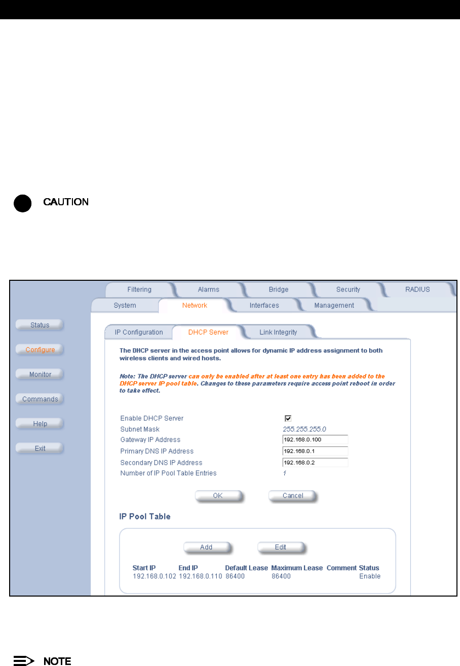
Advanced Configuration
38
•DNS Client Default Domain Name: The default domain name for the Access Point’s network (for example,
“proxim.com”). Contact your network administrator if you need assistance setting this parameter.
Advanced
•Default TTL (Time to Live): Time to Live (TTL) is a field in an IP packet that specifies how long in seconds the
packet can remain active on the network. The Access Point uses the default TTL for packets it generates for which
the transport layer protocol does not specify a TTL value. This parameter supports a range from 0 to 65535. By
default, TTL is 64.
DHCP Server
If your network does not have a DHCP Server, you can configure the AP-600 as a DHCP server to assign dynamic IP
addresses to Ethernet nodes and wireless clients.
!
Make sure there are no other DHCP servers on the network and do not enable the DHCP server without
checking with your network administrator first, as it could bring down the whole network. Also, the AP-600
must be configured with a static IP address before enabling this feature.
When the DHCP Server functionality is enabled, you can create one or more IP address pools from which to assign
addresses to network devices.
Figure 4-3 DHCP Server Configuration Screen
You can configure and view the following parameters within the
DHCP Server Configuration
screen:
•Enable DHCP Server: Place a check mark in the box provided to enable DHCP Server functionality.
You cannot enable the DHCP Server functionality unless there is at least one IP Pool Table Entry configured.
•Subnet Mask: This field is read-only and reports the Access Point’s current subnet mask. DHCP clients that
receive dynamic addresses from the AP-600 will be assigned this same subnet mask.
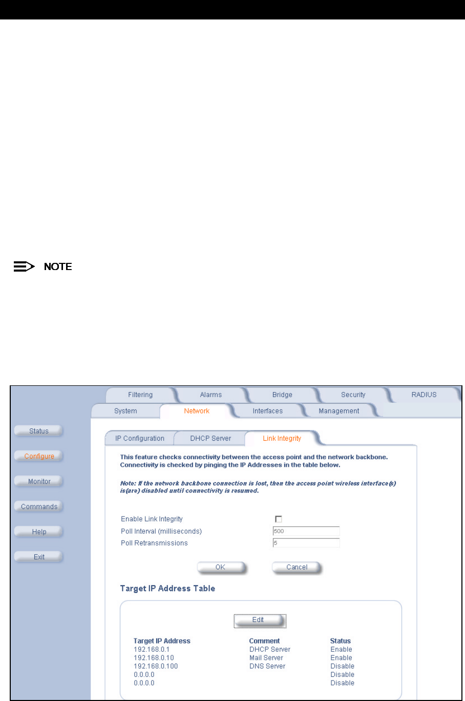
Advanced Configuration
39
•Gateway IP Address: The AP-600 will assign the specified address to its DHCP clients.
•Primary DNS IP Address: The AP-600 will assign the specified address to its DHCP clients.
•Secondary DNS IP Address: The AP-600 will assign the specified address to its DHCP clients.
•Number of IP Pool Table Entries: This is a read-only field that reports the number of IP address pools currently
configured.
•IP Pool Table Entry: This entry specifies a range of IP addresses that the AP can assign to its wireless clients.
Click Add to create a new entry. Click Edit to change an existing entry. Each entry contains the following field:
–Start IP Address
– End IP Address
–Default Lease Time (optional): The default time value for clients to retain the assigned IP address. DHCP
automatically renews IP Addresses without client notification. This parameter supports a range between 0 and
86400 seconds. The default is 86400 seconds.
–Maximum Lease Time (optional): The maximum time value for clients to retain the assigned IP address.
DHCP automatically renews IP Addresses without client notification. This parameter supports a range
between 0 and 86400 seconds. The default is 86400 seconds.
–Comment (optional)
–Status: IP Pools are enabled upon entry in the table. You can also disable or delete entries by changing this
field’s value.
You must reboot the Access Point before changes to any of these DHCP server parameters take effect.
Link Integrity
The Link Integrity feature checks the link between the AP-600 and the nodes on the Ethernet backbone. These nodes
are listed by IP address in the Link Integrity IP Address Table. The AP-600 periodically pings the nodes listed within the
table. If the AP-600 loses network connectivity (that is, the ping attempts fail), the AP-600 disables its wireless
interface until the connection is restored. This forces the unit’s wireless clients to switch to another Access Point that
still has a network connection. Note that this feature does not affect WDS links (if applicable).
Figure 4-4 Link Integrity Configuration Screen

Advanced Configuration
40
You can configure and view the following parameters within the
Link Integrity Configuration
screen:
•Enable Link Integrity: Place a check mark in the box provided to enable Link Integrity.
•Poll Interval (milliseconds): The interval between link integrity checks. Range is 500 - 15000 ms in increments of
500 ms; default is 500 ms.
•Poll Retransmissions: The number of times a poll should be retransmitted before the link is considered down.
Range is 0 to 255; default is 5.
•Target IP Address Entry: This entry specifies the IP address of a host on the network that the AP-600 will
periodically poll to confirm connectivity. The table can hold up to five entries. By default, all five entries are set to
0.0.0.0. Click Edit to update one or more entries. Each entry contains the following field:
– Target IP Address
– Comment (optional)
–Status: Set this field to Enable to specify that the Access Point should poll this device. You can also disable an
entry by changing this field’s value to Disable.
Interfaces
From the Interfaces tab, you configure the Access Point’s radio and Ethernet settings. Refer to the Wireless
parameters below that correspond to your Access Point model (AP-600a or AP-600b). The Ethernet settings apply to
both models.
–Wireless (AP-600a)
–Wireless (AP-600b)
–Ethernet
Wireless (AP-600a)
You can configure and view the following parameters within the
Wireless Interface Configuration
screen for an
AP-600a:
You must reboot the Access Point before any changes to these parameters take effect.
•Physical Interface Type: For the AP-600a, this field reports: “802.11a (OFDM 5 GHz).” OFDM stands for
Orthogonal Frequency Division Multiplexing; this is the name for the radio technology used by 802.11a devices.
•MAC Address: This is a read-only field that displays the unique MAC (Media Access Control) address for the
Access Point’s wireless interface. The MAC address is assigned at the factory.
•Regulatory Domain: Reports the regulatory domain for which the AP-600a is certified. Not all features or
channels are available in all countries. The available regulatory domains include:
—U.S./Canada -- FCC (5.15-5.35 GHz, 5.725-5.850 GHz)
—Europe -- ETSI (5.15-5.25 GHz only)
—Europe -- ETSI (5.15-5.35 GHz)
—Japan -- MMK (5.15-5.25 GHz)
—Singapore (5.15-2.25 GHz, 5.725-5.850 GHz)
•Network Name (SSID): Enter a Network Name (between 2 and 31 characters long) for the wireless network. You
must configure each wireless client to use this name as well.
•Auto Channel Select: The AP-600a scans the area for other Access Points and selects a free or relatively unused
communication channel. This helps prevent interference problems and increases network performance. By default
this feature is enabled. Note that you cannot disable Auto Channel Select for 802.11a products in Europe (see
Dynamic Frequency Selection (DFS) for details). See 802.11a Channel Frequencies for the AP-600a for a list of
Channels.
•Turbo Mode: The AP-600a supports 2X Turbo Mode, an extension of the IEEE 802.11a standard that provides
twice the data rate. Note that 2X Turbo mode is not defined in the IEEE 802.11a specification. By default, Turbo
mode is disabled. Turbo mode is not available in all countries.
•Frequency Channel: When Auto Channel Select is enabled, this field is read-only and displays the Access Point’s
current operating Channel. When Auto Channel Select is disabled, you can specify the Access Point’s channel. If
you decide to manually set the unit’s Channel, ensure that nearby devices do not use the same frequency.
Available Channels vary based on regulatory domain and the Turbo Mode setting. See 802.11a Channel
Frequencies for the AP-600a. Note that you cannot manually set the channel for 802.11a products in Europe (see
Dynamic Frequency Selection (DFS) for details).
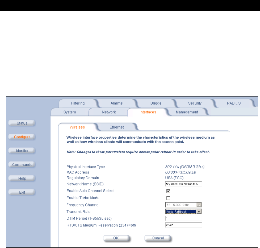
Advanced Configuration
41
•Transmit Rate: Use the drop-down menu to select a specific transmit rate for the AP-600a. Choose between 6, 9,
12, 18, 24, 36, 48, 54 Mbits/s, and Auto Fallback for standard 802.11a mode. If Turbo mode is enabled, choose
between 12, 18, 24, 36, 48, 72, 98, 108 Mbits/s, and Auto Fallback. Auto Fallback is the default setting; it allows
the AP-600a unit to select the best transmit rate based on the cell size.
•DTIM Period: The Deferred Traffic Indicator Map (DTIM) is used with clients that have power management
enabled. DTIM should be left at 1, the default value, if any clients have power management enabled. This
parameter supports a range between 1 and 65535.
•RTS/CTS Medium Reservation: This parameter affects message flow control and should not be changed under
normal circumstances. Range is 0 to 2347. When set to a value between 0 and 2347, the Access Point uses the
RTS/CTS mechanism for packets that are the specified size or greater. When set to 2347 (the default setting),
RTS/CTS is disabled. See RTS/CTS Medium Reservation for more information.
Figure 4-5 Wireless Interface Configuration Screen (AP-600a)
Dynamic Frequency Selection (DFS)
AP-600a units sold in Europe use a technique called Dynamic Frequency Selection (DFS) to automatically select an
operating channel. During boot-up, the AP-600a scans the available frequency and selects a channel that is free of
interference. If the AP-600a subsequently detects interference on its channel, it automatically reboots and selects
another channel that is free of interference.
DFS only applies to AP-600a devices used in Europe (i.e., units whose regulatory domain is set to ETSI). The
European Telecommunications Standard Institute (ETSI) requires that 802.11a devices use DFS to prevent
interference with radar systems and other devices that already occupy the 5 GHz band.
If you are using an AP-600a in Europe, keep in mind the following:
•DFS is not a configurable parameter. It is always enabled and cannot be disabled.
•You cannot manually select the device’s operating channel; you must let DFS select the channel.
•You cannot configure the Auto Channel Select option. Within the HTTP interface, this option always appears
enabled.

Advanced Configuration
42
RTS/CTS Medium Reservation
The 802.11 standard supports optional RTS/CTS communication based on packet size. Without RTS/CTS, a sending
radio listens to see if another radio is already using the medium before transmitting a data packet. If the medium is
free, the sending radio transmits its packet. However, there is no guarantee that another radio is not transmitting a
packet at the same time, causing a collision. This typically occurs when there are hidden nodes (clients that can
communicate with the Access Point but are out of range of each other) in very large cells.
When RTS/CTS occurs, the sending radio first transmits a Request to Send (RTS) packet to confirm that the medium
is clear. When the receiving radio successfully receives the RTS packet, it transmits back a Clear to Send (CTS)
packet to the sending radio. When the sending radio receives the CTS packet, it sends the data packet to the receiving
radio. The RTS and CTS packets contain a reservation time to notify other radios (including hidden nodes) that the
medium is in use for a specified period. This helps to minimize collisions. While RTS/CTS adds overhead to the radio
network, it is particularly useful for large packets that take longer to resend after a collision occurs.
RTS/CTS Medium Reservation is an advanced parameter and supports a range between 0 and 2347 bytes. When set
to 2347 (the default setting), the RTS/CTS mechanism is disabled. When set to 0, the RTS/CTS mechanism is used for
all packets. When set to a value between 0 and 2347, the Access Point uses the RTS/CTS mechanism for packets that
are the specified size or greater. You should not need to enable this parameter for most networks unless you suspect
that the wireless cell contains hidden nodes.
Wireless (AP-600b)
You can configure and view the following parameters within the
Wireless Interface Configuration
screen for an
AP-600b:
You must reboot the Access Point before any changes to these parameters take effect.
•Physical Interface Type: For the AP-600b, this field reports: “802.11b (DSSS 2.4 GHz).” DSSS stands for Direct
Sequence Spread Spectrum; this is the name for the radio technology used by 802.11b devices.
•MAC Address: This is a read-only field that displays the unique MAC (Media Access Control) address for the
Access Point’s wireless interface. The MAC address is assigned at the factory.
•Regulatory Domain: Reports the regulatory domain for which the AP-600b is certified. Not all features or
channels are available in all countries. The available regulatory domains include:
—U.S./Canada -- FCC (2.4000-2.4835 GHz)
—Europe -- ETSI (2.4000-2.4835 GHz; France only: 2.4465-2.4835 GHz)
—Japan -- MKK (2.4000 GHz-2.4970 GHz)
•Network Name (SSID): Enter a Network Name (between 2 and 31 characters long) for the wireless network. You
must configure each wireless client to use this name as well.
•Auto Channel Select: The AP-600b scans the area for other Access Points and selects a free or relatively unused
communication channel. This helps prevent interference problems and increases network performance. By default
this feature is enabled; see 802.11b Channel Frequencies for the AP-600b for a list of Channels. However, if you
are setting up a Wireless Distribution System (WDS), it must be disabled. See Wireless Distribution System (WDS)
for more information.
•Frequency Channel: When Auto Channel Select is enabled, this field is read-only and displays the Access Point’s
current operating channel. When Auto Channel Select is disabled, you can specify the Access Point’s operating
channel. If you decide to manually set the unit’s channel, ensure that nearby devices do not use the same
frequency (unless you are setting up a WDS). Available Channels vary based on regulatory domain. See 802.11b
Channel Frequencies for the AP-600b.
•Distance Between APs: Set to Large, Medium, Small, Microcell, or Minicell depending on the site survey for
your system. By default, this parameter is set to Large. The distance value is related to the Multicast Rate
(described next). In general, a larger distance between APs means that your clients operate a slower data rates
(on average). See Distance Between APs for more information.
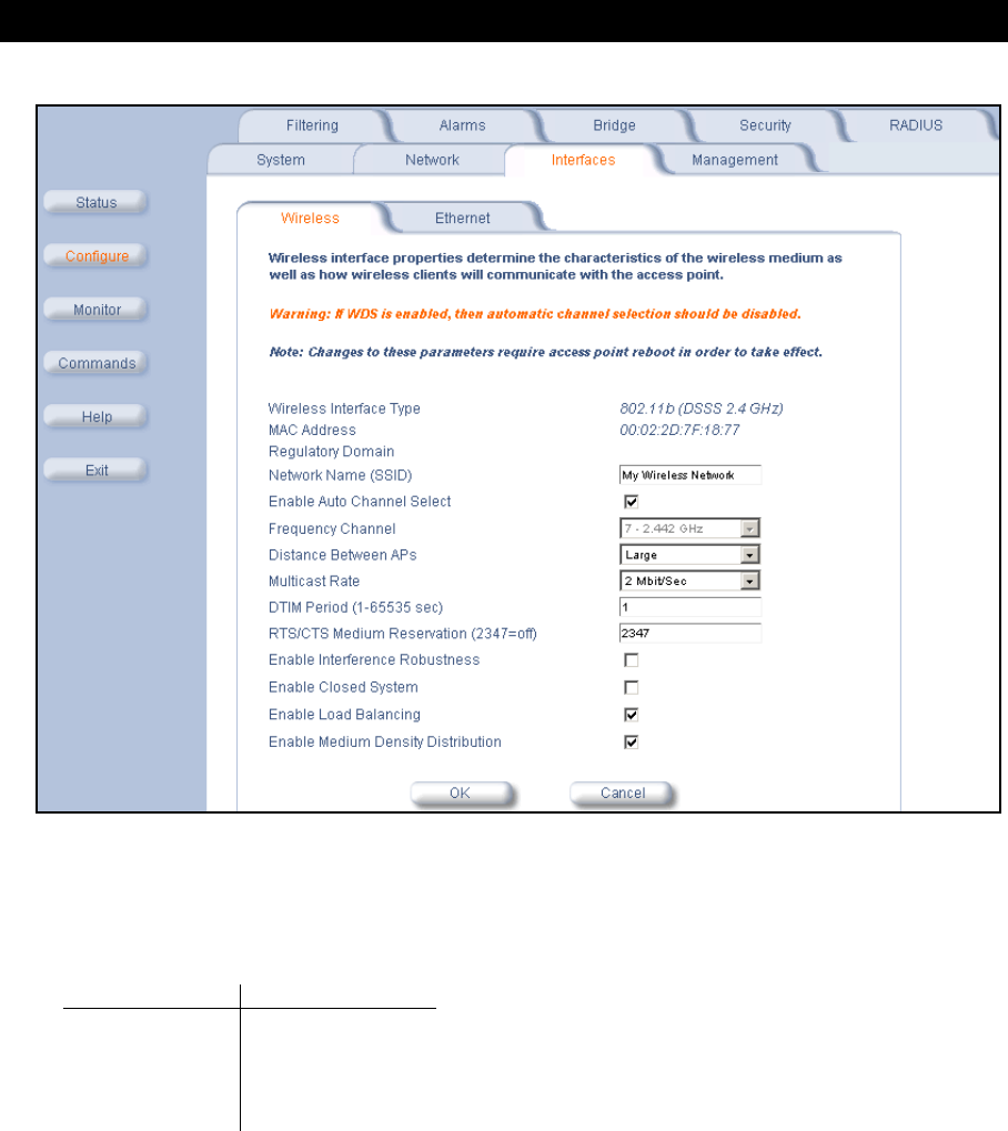
Advanced Configuration
43
Figure 4-6 Wireless Interface Configuration Screen (AP-600b)
•Multicast Rate: Sets the rate at which Multicast messages are sent. This value is related to the Distance Between
APs parameter (described previously). The table below displays the possible Multicast Rates based on the
Distance between APs setting. By default, this parameter is set to 2 Mbits/sec. See Multicast Rate for more
information.
•DTIM Period: The Deferred Traffic Indicator Map (DTIM) is used with clients that have power management
enabled. DTIM should be left at 1, the default value, if any clients have power management enabled. This
parameter supports a range between 1 and 65535.
•RTS/CTS Medium Reservation: This parameter affects message flow control and should not be changed under
normal circumstances. Range is 0 to 2347. When set to a value between 0 and 2347, the Access Point uses the
RTS/CTS mechanism for packets that are the specified size or greater. When set to 2347 (the default setting),
RTS/CTS is disabled. See RTS/CTS Medium Reservation for more information.
•Interference Robustness: Enable this option if other electrical devices in the 2.4 GHz frequency band (such as a
microwave oven or a cordless phone) may be interfering with the wireless signal. The AP-600b will automatically
fragment large packets into multiple smaller packets when interference is detected to increase the likelihood that
the messages will be received in the presence of interference. The receiving radio reassembles the original packet
once all fragments have been received. This option is disabled by default.
•Closed System: Check this box to allow only clients configured with the Access Point’s specific Network Name to
associate with the Access Point. When enabled, a client configured with the Network Name “ANY” cannot connect
to the AP-600b. This option is disabled by default.
Distance between APs Multicast Rate
Large 1 and 2 Mbits/sec
Medium 1, 2, and 5.5 Mbits/sec
Small 1, 2, 5.5 and 11 Mbits/sec
Minicell 1, 2, 5.5 and 11 Mbits/sec
Microcell 1, 2, 5.5 and 11 Mbits/sec
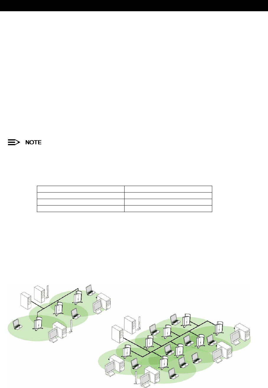
Advanced Configuration
44
•Load Balancing: Enable this option so clients can evaluate which Access Point to associate with, based on
current AP loads. This feature is enabled by default; it helps distribute the wireless load between APs. This feature
is not available if you are using an ORiNOCO 802.11a/b ComboCard or a non-ORiNOCO client with the AP-600b.
•Medium Density Distribution: When enabled, the Access Point automatically notifies wireless clients of its
Distance Between APs, Interference Robustness, and RTS/CTS Medium Reservation settings. This feature is
enabled by default and allows clients to automatically adopt the values used by its current Access Point (even if
these values differ from the client’s default values or from the values supported by other Access Points). Note that
this feature is not available if you are using an ORiNOCO 802.11a/b ComboCard or a non-ORiNOCO client with
the AP-600b. Proxim recommends that you leave this parameter enabled, particularly if you have ORiNOCO
clients on your wireless network (leaving this parameter enabled should not adversely affect the performance of
any ORiNOCO 802.11a/b ComboCards or non-ORiNOCO cards on your network).
Distance Between APs
Distance Between APs defines how far apart (physically) your AP-600b devices are located, which in turn determines
the size of your cell. Cells of different sizes have different capacities and, therefore, suit different applications. For
instance, a typical office has many stations that require high bandwidth for complex, high-speed data processing. In
contrast, a typical warehouse has a few forklifts requiring low bandwidth for simple transactions.
This feature is not available if you are using an ORiNOCO 802.11a/b ComboCard or a non-ORiNOCO client
with the AP-600b.
Cell capacities are compared in the following table, which shows that small cells suit most offices and large cells suit
most warehouses:
Coverage
The number of Access Points in a set area determines the network coverage for that area. A large number of
Access Points covering a small area is a high-density cell. A few Access Points, or even a single unit, covering the
same small area would result in a low-density cell, even though in both cases the actual area did not change — only
the number of Access Points covering the area changed.
In a typical office, a high density area consists of a number of Access Points installed every 20 feet and each
Access Point generates a small radio cell with a diameter of about 10 feet. In contrast, a typical warehouse might have
a low density area consisting of large cells (with a diameter of about 90 feet) and Access Points installed every
200 feet.
Figure 4-7 Low Density vs. Ultra High Density Network
The Distance Between Cells parameter supports five values: Large, Medium, Small, Minicell, and Microcell.
Small Cell Large Cell
Physically accommodates few stations Physically accommodates many stations
High cell bandwidth per station Lower cell bandwidth per station
High transmit rate Lower transmit rate
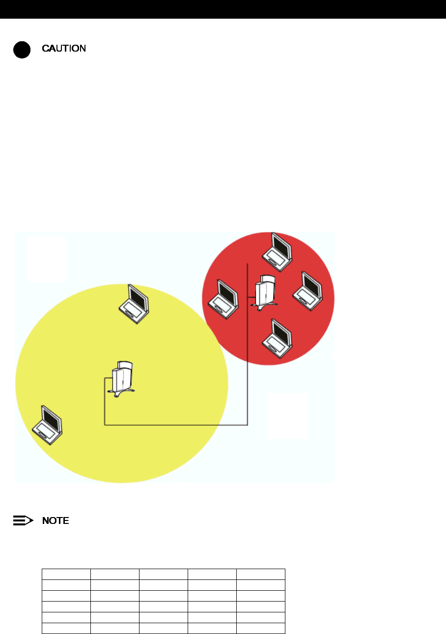
Advanced Configuration
45
!
The distance between APs should not be approximated. It is calculated by means of a manual Site Survey, in
which an AP-600b is set up and clients are tested throughout the area to determine signal strength and
coverage, and local limits such as physical interference are investigated. From these measurements the
appropriate cell size and density is determined, and the optimum distance between APs is calculated to suit
your particular business requirements. Contact your reseller for information on how to conduct a Site Survey.
Multicast Rate
The multicast rate determines the rate at which broadcast and multicast packets are transmitted by the Access Point to
the wireless network. Stations that are closer to the Access Point can receive multicast packets at a faster data rate
than stations that are farther away from the AP. Therefore, you should set the Multicast Rate based on the size of the
Access Point’s cell. For example, if the Access Point’s cell is very small (e.g., Distance Between APs is set to
Microcell), you can expect that all stations should be able to successfully receive multicast packets at 11 MBits/sec so
you can set Multicast Rate to 11 Mbits/sec. However, if the Access Point’s cell is large, you need to accommodate
stations that may not be able to receive multicast packets at the higher rates; in this case, you should set Multicast
Rate to 1 or 2 Mbits/sec.
Figure 4-8 1 Mbits/s and 11 Mbits/s Multicast Rates
There is an inter-dependent relationship between the Distance between APs and the Multicast Rate. In
general, larger systems operate at a lower average transmit rate. The variation between Multicast Rate and
Distance Between APs is presented in the following table:
The Distance Between APs must be set before the Multicast Rate, because when you select the Distance
Between APs, the appropriate range of Multicast values automatically populates the drop-down menu. This
feature is not available if you are using an ORiNOCO 802.11a/b ComboCard or a non-ORiNOCO client with
the AP-600b.
1.0 Mbit/s 2.0 Mbits/s 5.5 Mbits/s 11 Mbits/s
Large yes yes
Medium yes yes yes
Small yes yes yes yes
Minicell yes yes yes yes
Microcell yes yes yes yes
11 Mbits/s
1 Mbit/s
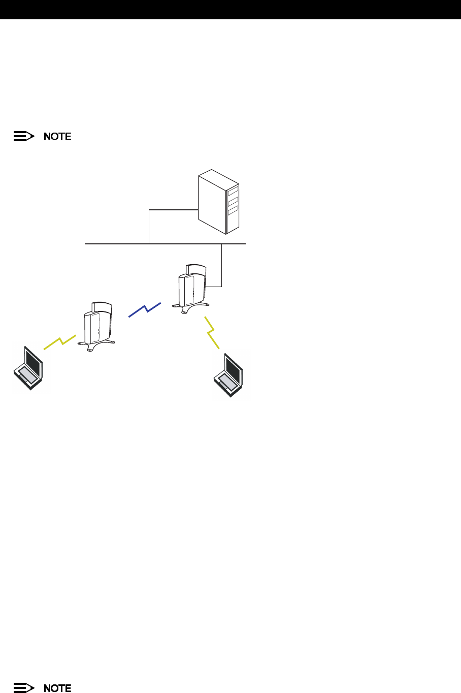
Advanced Configuration
46
Wireless Distribution System (WDS)
A Wireless Distribution System (WDS) creates a link between two AP-600b units over their radio interfaces. This link
relays traffic from one AP-600b that does not have Ethernet connectivity to a second AP-600b that has Ethernet
connectivity. WDS allows you to configure up to six (6) point-to-point links between Access Points.
In the WDS Example below, AP 1 and AP 2 communicate over a WDS link (represented by the blue line). This link
provides Client 1 with access to network resources even though AP 1 is not directly connected to the Ethernet
network. Packets destined for or sent by the client are relayed between the Access Points over the WDS link.
This feature is not available with the AP-600a.
Figure 4-9 WDS Example
Bridging WDS
Each WDS link is mapped to a logical WDS port on the AP-600b. WDS ports behave like Ethernet ports rather than like
standard wireless interfaces: on a BSS port, an Access Point learns by association and from frames; on a WDS or
Ethernet port, an Access Point learns from frames only. When setting up a WDS, keep in mind the following:
•The WDS link shares the communication bandwidth with the clients. Therefore, while the maximum data rate for
the Access Point’s cell is still 11 Mb, client throughput will decrease when the WDS link is active.
•If there is no partner MAC address configured in the WDS table, the WDS port remains disabled.
•Each WDS port on a single AP-600b should have a unique partner MAC address. Do not enter the same MAC
address twice in an AP-600b’s WDS port list.
•Each Access Point that is a member of the WDS must have the same Channel setting to communicate with each
other.
•Each Access Point that is a member of the WDS must have the same WEP Encryption settings. WDS does not
use 802.1x. Therefore, if you want to encrypt the WDS link, you must configure each Access Point to use WEP
encryption (either WEP encryption only or Mixed Mode), and each Access Point must have the same Encryption
Key(s). See Security.
•If your network does not support spanning tree, be careful to avoid creating network loops between AP-600b
devices. For example, creating a WDS link between two Access Points connected to the same Ethernet network
will create a network loop (if spanning tree is disabled).
WDS Setup Procedure
You must disable Auto Channel Select to create a WDS.
AP 1
AP 2
Client 1 Client 2
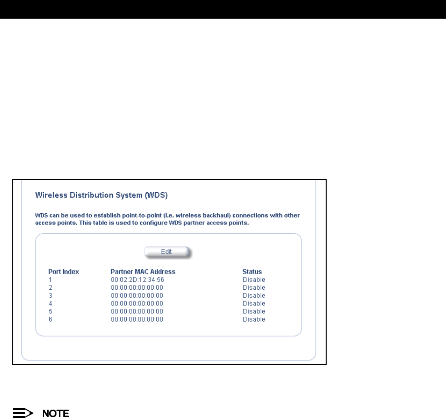
Advanced Configuration
47
To setup a wireless backbone follow the steps below for each AP-600b that you wish to include in the Wireless
Distribution System.
1. Confirm that Auto Channel Select is disabled.
2. Write down the MAC Address of the radio that you wish to include in the Wireless Distribution System.
3. Open the
Wireless Interface Configuration
screen.
4. Scroll down to the Wireless Distribution System heading.
5. Click the Edit button to update the Wireless Distribution System (WDS) Table.
6. Enter the MAC Address that you wrote down in Step 2 in one of the Partner MAC Address field of the Wireless
Distribution Setup window.
7. Set the Status of the device to Enable.
8. Click OK.
Figure 4-10 WDS Configuration
9. Restart the AP-600b.
To set up a Wireless Distribution System (WDS) with 802.1x, set each Access Point’s 802.1x Security Mode to
Mixed and assign each unit in the WDS the same Encryption Key 1. See Security.
Ethernet
Select the desired speed and transmission mode from the drop-down menu. Half-duplex means that only one side can
transmit at a time and full-duplex allows both sides to transmit. When set to auto-duplex, the AP-600 negotiates with its
switch or hub to automatically select the highest throughput option supported by both sides.
For best results, Proxim recommends that you configure the Ethernet setting to match the speed and transmission
mode of the device the Access Point is connected to (such as a hub or switch). If in doubt, leave this setting at its
default, auto-speed-auto-duplex. Choose between:
•10 Mbit/s - half duplex, full duplex, or auto duplex
•100 Mbit/s - half duplex, full duplex, or auto duplex
•auto speed - half duplex or auto duplex

Advanced Configuration
48
Management
The Management category contains three sub-categories.
–Passwords
–IP Access Table
–Services
Passwords
You can configure the following passwords:
•SNMP Read Password: The password for read access to the AP-600 using SNMP. Enter a password in both the
Password field and the Confirm field. The default password is “public”.
•SNMP Read/Write Password: The password for read and write access to the AP-600 using SNMP. Enter a
password in both the Password field and the Confirm field. The default password is “public”.
•Telnet (CLI) Password: The password for the CLI interface (via serial or Telnet). Enter a password in both the
Password field and the Confirm field. The default password is “public”.
•HTTP (Web) Password: The password for the Web browser HTTP interface. Enter a password in both the
Password field and the Confirm field. The default password is “public”.
For security purposes Proxim recommends changing ALL PASSWORDS from the default “public”
immediately, to restrict access to your network devices to authorized personnel. If you lose or forget your
password settings, you can always perform the Reset to Factory Default Procedure.
IP Access Table
The Management IP Access table limits in-band management access to the IP addresses or range of IP addresses
specified in the table. This feature applies to all management options (SNMP, HTTP, and CLI) except for CLI
management over the serial port. To configure this table, click Add and set the following parameters:
•IP Address: Enter the IP Address for the management station.
•IP Mask: Enter a mask that will act as a filter to limit access to a range of IP Addresses based on the IP Address
you already entered.
–The IP mask 255.255.255.255 would authorize the single station defined by the IP Address to configure the
Access Point. The AP-600 would ignore commands from any other IP address. In contrast, the IP mask
255.255.255.0 would allow any device that shares the first three octets of the IP address to configure the
AP-600. For example, if you enter an IP address of 10.20.30.1 with a 255.255.255.0 subnet mask, any IP
address between 10.20.30.1 and 10.20.30.254 will have access to the AP’s management interfaces.
•Comment: Enter an optional comment, such as the station name.
To edit or delete an entry, click Edit. Edit the information, or select Enable, Disable, or Delete from the Status
pull-down menu.
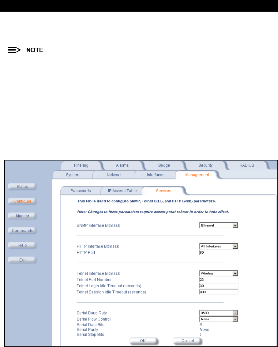
Advanced Configuration
49
Services
You can configure the following management services:
You must reboot the Access Point if you change the HTTP Port or Telnet Port.
SNMP Settings
•SNMP Interface Bitmask: Configure the interface or interfaces (Ethernet, Wireless, All Interfaces) from which
you will manage the AP-600 via SNMP. You can also select Disabled to prevent a user from accessing the AP-600
device via SNMP.
HTTP Access
•HTTP Interface Bitmap: Configure the interface or interfaces (Ethernet, Wireless, All Interfaces) from which you
will manage the AP-600 via the Web interface. For example, to allow Web configuration via the Ethernet network
only, set HTTP Interface Bitmask to Ethernet. You can also select Disabled to prevent a user from accessing the
AP-600 from the Web interface.
•HTTP Port: Configure the HTTP port from which you will manage the AP-600 via the Web interface. By default, the
HTTP port is 80.
Figure 4-11 Management Services Configuration Screen

Advanced Configuration
50
Telnet Configuration Settings
•Telnet Interface Bitmask: Select the interface (Ethernet, Wireless, All Interfaces) from which you can manage
the AP-600 via telnet. This parameter can also be used to Disable telnet management.
•Telnet Port: The default port number for Telnet applications is 23. However, you can use this field if you want to
change the Telnet port for security reasons (but your Telnet application also must support the new port number you
select).
•Login Idle Timeout (seconds): Enter the number of seconds the system will wait for a login attempt. The AP-600
terminates the session when it times out. The range is 1 to 300 seconds; the default is 30 seconds.
•Session Idle Timeout (seconds): Enter the number of seconds the system will wait during a session while there
is no activity. The AP-600 will terminate the session on timeout. The range is 1 to 36000 seconds; the default is
900 seconds.
Serial Configuration Settings
The serial port interface on the AP-600 is enabled at all times. See Setting IP Address using Serial Port and Normal
CLI for information on how to access the CLI interface via the serial port. You can configure and view following
parameters:
–Baud Rate: Select the serial port speed (bits per second). Choose between 2400, 4800, 9600, 19200, 38400, or
57600; the default Baud Rate is 9600.
–Flow Control: Select either None (default) or Xon/Xoff (software controlled) data flow control.
To avoid potential problems when communicating with the AP-600 through the serial port, Proxim
recommends that you leave the Flow Control setting at None (the default value).
•Serial Data Bits: This is a read-only field and displays the number of data bits used in serial communication
(8 data bits by default).
•Serial Parity: This is a read-only field and displays the number of parity bits used in serial communication
(no parity bits by default).
•Serial Stop Bits: This is a read-only field that displays the number of stop bits used in serial communication
(1 stop bit by default).
The serial port bit configuration is commonly referred to as 8N1.
Filtering
The Access Point’s Packet Filtering features help control the amount of traffic exchanged between the wired and
wireless networks. There are four sub-categories under the Filtering heading.
–Ethernet Protocol
–Static MAC
–Advanced
–TCP/UDP Port
Ethernet Protocol
The Ethernet Protocol Filter blocks or forwards packets based on the Ethernet protocols they support.
Follow these steps to configure the Ethernet Protocol Filter:
1. Select the interfaces or interfaces that will implement the filter from the Ethernet Protocol Filtering drop-down
menu.
•Ethernet: Packets are examined at the Ethernet interface
•Wireless: Packets are examined at the Wireless interface
•All Interfaces: Packets are examined at both interfaces
•Disabled: The filter is not used
2. Select the Filter Operation Type.
•If set to Passthru, only the enabled Ethernet Protocols listed in the Filter Table will pass through the bridge.
•If set to Block, the bridge will block enabled Ethernet Protocols listed in the Filter Table.

Advanced Configuration
51
3. Configure the Ethernet Protocol Filter Table. This table is pre-populated with existing Ethernet Protocol Filters,
however, you may enter additional filters by specifying the appropriate parameters.
•To add an entry, click Add, and then specify the Protocol Number and a Protocol Name.
—Protocol Number: Enter the protocol number. See http://www.iana.org/assignments/ethernet-numbers
for a list of protocol numbers.
—Protocol Name: Enter related information, typically the protocol name.
•To edit or delete an entry, click Edit and change the information, or select Enable, Disable, or Delete from the
Status drop-down menu.
•An entry’s status must be enabled in order for the protocol to be subject to the filter.
Static MAC
The Static MAC Address filter optimizes the performance of a wireless (and wired) network. When this feature is
properly configured, the AP-600 can block traffic between wired devices and wireless devices based on MAC address.
For example, you can set up a Static MAC filter to prevent wireless clients from communicating with a specific server
on the Ethernet network. You can also use this filter to block unnecessary multicast packets from being forwarded to
the wireless network.
The Static MAC Filter is an advanced feature. You may find it easier to control wireless traffic via other filtering
options, such as Ethernet Protocol Filtering.
Each static MAC entry contains the following fields:
•Wired MAC Address
•Wired Mask
•Wireless MAC Address
•Wireless Mask
•Comment: This field is optional.
Each MAC Address or Mask is comprised of 12 hexadecimal digits (0-9, A-F) that correspond to a 48-bit identifier.
(Each hexadecimal digit represents 4 bits (0 or 1).)
Taken together, a MAC Address/Mask pair specifies an address or a range of MAC addresses that the AP-600 will look
for when examining packets. The AP-600 uses Boolean logic to perform an “AND” operation between the MAC
Address and the Mask at the bit level. However, for most users, you do not need to think in terms of bits. It should be
sufficient to create a filter using only the hexadecimal digits 0 and F in the Mask (where 0 is any value and F is the
value specified in the MAC address). A Mask of 00:00:00:00:00:00 corresponds to all MAC addresses, and a Mask of
FF:FF:FF:FF:FF:FF applies only to the specified MAC Address.
For example, if the MAC Address is 00:20:A6:12:54:C3 and the Mask is FF:FF:FF:00:00:00, the AP-600 will examine
the source and destination addresses of each packet looking for any MAC address starting with 00:20:A6. If the Mask
is FF:FF:FF:FF:FF:FF, the AP-600 will only look for the specific MAC address (in this case, 00:20:A6:12:54:C3).
When creating a filter, you can configure the Wired parameters only, the Wireless parameters only, or both sets of
parameters. Which parameters to configure depends upon the traffic that you want block:
–To prevent all traffic from a specific wired MAC address from being forwarded to the wireless network, configure
only the Wired MAC Address and Wired Mask (leave the Wireless MAC Address and Wireless Mask set to all
zeros).
–To prevent all traffic from a specific wireless MAC address from being forwarded to the wired network, configure
only the Wireless MAC address and Wireless Mask (leave the Wired MAC Address and Wired Mask set to all
zeros).
–To block traffic between a specific wired MAC address and a specific wireless MAC address, configure all four
parameters.
To create an entry, click Add and enter the appropriate MAC addresses and Masks to setup a filter. The entry is
enabled automatically when saved. To edit an entry, click Edit. To disable or remove an entry, click Edit and change
the Status field from Enable to Disable or Delete.
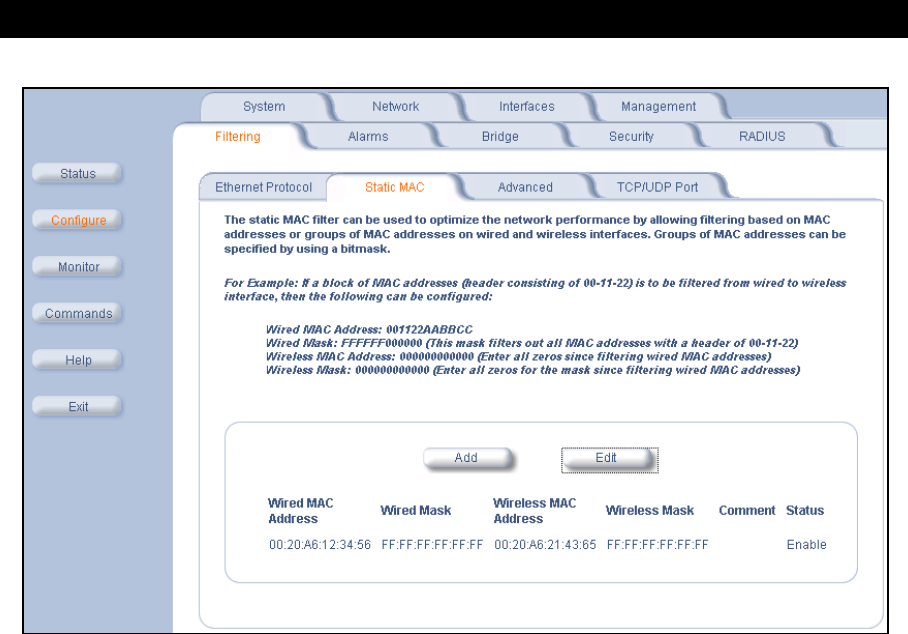
Advanced Configuration
52
Figure 4-12 Static MAC Configuration Screen
Static MAC Filter Examples
Consider a network that contains a wired server and three wireless clients. The MAC address for each unit is as
follows:
–Wired Server: 00:40:F4:1C:DB:6A
–Wireless Client 1: 00:02:2D:51:94:E4
–Wireless Client 2: 00:02:2D:51:32:12
–Wireless Client 3: 00:20:A6:12:4E:38
Prevent Two Specific Devices from Communicating
Configure the following settings to prevent the Wired Server and Wireless Client 1 from communicating:
•Wired MAC Address: 00:40:F4:1C:DB:6A
•Wired Mask: FF:FF:FF:FF:FF:FF
•Wireless MAC Address: 00:02:2D:51:94:E4
•Wireless Mask: FF:FF:FF:FF:FF:FF
Result: Traffic between the Wired Server and Wireless Client 1 is blocked. Wireless Clients 2 and 3 can still
communicate with the Wired Server.
Prevent Multiple Wireless Devices From Communicating With a Single Wired Device
Configure the following settings to prevent Wireless Clients 1 and 2 from communicating with the Wired Server.
•Wired MAC Address: 00:40:F4:1C:DB:6A
•Wired Mask: FF:FF:FF:FF:FF:FF
•Wireless MAC Address: 00:02:2D:51:94:E4
•Wireless Mask: FF:FF:FF:00:00:00
Result: When a logical “AND” is performed on the Wireless MAC Address and Wireless Mask, the result corresponds
to any MAC address beginning with the 00:20:2D prefix. Since Wireless Client 1 and Wireless Client 2 share the same
prefix (00:02:2D), traffic between the Wired Server and Wireless Clients 1 and 2 is blocked. Wireless Client 3 can still
communicate with the Wired Server since it has a different prefix (00:20:A6).

Advanced Configuration
53
Prevent All Wireless Devices From Communicating With a Single Wired Device
Configure the following settings to prevent all three Wireless Clients from communicating with Wired Server 1.
•Wired MAC Address: 00:40:F4:1C:DB:6A
•Wired Mask: FF:FF:FF:FF:FF:FF
•Wireless MAC Address: 00:00:00:00:00:00
•Wireless Mask: 00:00:00:00:00:00
Result: The Access Point blocks all traffic between Wired Server 1 and all wireless clients.
Prevent A Wireless Device From Communicating With the Wired Network
Configure the following settings to prevent Wireless Client 3 from communicating with any device on the Ethernet.
•Wired MAC Address: 00:00:00:00:00:00
•Wired Mask: 00:00:00:00:00:00
•Wireless MAC Address: 00:20:A6:12:4E:38
•Wireless Mask: FF:FF:FF:FF:FF:FF
Result: The Access Point blocks all traffic between Wireless Client 3 and the Ethernet network.
Prevent Messages Destined for a Specific Multicast Group from Being Forwarded to the Wireless LAN
If there are devices on your Ethernet network that use multicast packets to communicate and these packets are not
required by your wireless clients, you can set up a Static MAC filter to preserve wireless bandwidth. For example, if
routers on your network use a specific multicast address (such as 01:00:5E:00:32:4B) to exchange information, you
can set up a filter to prevent these multicast packets from being forwarded to the wireless network:
•Wired MAC Address: 01:00:5E:00:32:4B
•Wired Mask: FF:FF:FF:FF:FF:FF
•Wireless MAC Address: 00:00:00:00:00:00
•Wireless Mask: 00:00:00:00:00:00
Result: The Access Point does not forward any packets that have a destination address of 01:00:5E:00:32:4B to the
wireless network.
Advanced
You can configure the following advanced filtering options:
•Enable Proxy ARP: Place a check mark in the box provided to allow the Access Point to respond to Address
Resolution Protocol (ARP) requests for wireless clients. When enabled, the AP-600 answers ARP requests for
wireless stations without actually forwarding them to the wireless network. If disabled, the Access Point will bridge
ARP requests for wireless clients to the wireless LAN.
•Enable IP/ARP Filtering: Place a check mark in the box provided to allow IP/ARP filtering based on the IP/ARP
Filtering Address and IP Mask. Leave the box unchecked to prevent filtering. If enabled, you should also configure
the IP/ARP Filtering Address and IP/ARP IP Mask.
–IP/ARP Filtering Address: Enter the Network filtering IP Address.
–IP/ARP IP Mask: Enter the Network Mask IP Address.
The following protocols are listed in the Advanced Filter Table:
•Deny IPX RIP
•Deny IPX SAP
•Deny IPX LSP
•Deny IP Broadcasts
•Deny IP Multicasts
The AP-600 can filter these protocols in the wireless-to-Ethernet direction, the Ethernet-to-wireless direction, or in both
directions. Click Edit and use the Status field to Enable or Disable the filter.
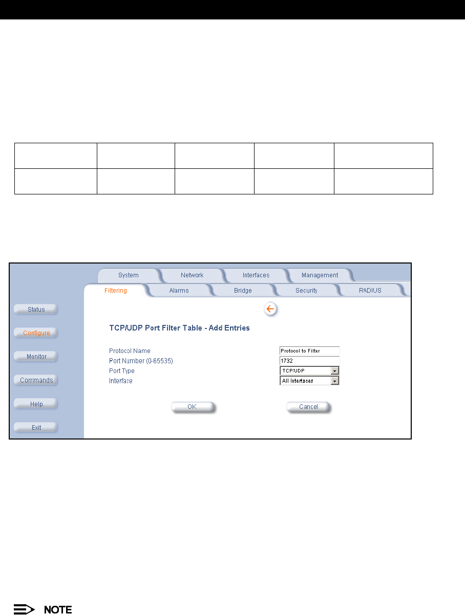
Advanced Configuration
54
TCP/UDP Port
Port-based filtering enables you to control wireless user access to network services by selectively blocking TCP/UDP
protocols through the AP-600. A user specifies a Protocol Name, Port Number, Port Type (TCP, UDP, or TCP/UDP),
and filtering interfaces (Wireless only, Ethernet only, all interfaces, or no interfaces) in order to block access to
services, such as Telnet and FTP, and traffic, such as NETBIOS and HTTP.
For example, an AP-600 with the following configuration would discard frames received on its Wireless radio with a
UDP destination port number of 137, effectively blocking NETBIOS Name Service packets.
Adding TCP/UDP Port Filters
1. Place a check mark in the box labeled Enable TCP/UDP Port Filtering.
2. Click Add under the
TCP/UDP Port Filter Table
heading.
Figure 4-13 Adding a New TCP/UDP Port Filter Entry
3. In the
TCP/UDP Port Filter Table
, enter the Protocol Names to filter.
4. Set the destination Port Number (a value between 0 and 65535) to filter. See the IANA Web site at
http://www.iana.org/assignments/port-numbers for a list of assigned port numbers and their descriptions.
5. Set the Port Type for the protocol: TCP, UDP, or both (TCP/UDP).
6. Set the Interface to filter:
•Wireless
•Ethernet
•All interfaces
•No interfaces
7. Click OK.
Filters are enabled by default. Packets that the AP-600 receives on the specified interface(s) with the specified
TCP/UDP destination port, are discarded.
Editing TCP/UDP Port Filters
1. Click Edit under the
TCP/UDP Port Filter Table
heading.
2. Make any changes to the Protocol Name or Port Number for a specific entry, if necessary.
3. In the row that defines the port, set the Status to Enable, Disable, or Delete, as appropriate.
4. Select OK.
Protocol Type
(TCP/UDP)
Destination
Port Number
Protocol Name Interface Status
(Enable/Disable)
UDP 137 NETBIOS
Name Service
Wireless Enable

Advanced Configuration
55
Alarms
This category has three sub-categories.
–Groups
–Alarm Host Table
–Syslog
Groups
There are seven alarm groups that can be enabled or disabled:
•Enable Configuration Alarms
•Enable Security Alarms
•Enable Wireless Alarms
•Enable Operational Alarms
•Enable Flash Memory Alarms
•Enable TFTP Alarms
•Enable Image Alarms
Place a check mark in the box provided to enable a specific group. Remove the check mark from the box to disable the
alarms.
These alarm groups correspond to System Alarms that are displayed in the HTTP interface’s System Status screen
and to traps that are sent by the AP-600 to the SNMP managers specified in the Alarm Host Table.
See System Alarms (Traps) for the list of alarms contained in each group.
Alarm Host Table
To add an entry and enable the AP-600 to send SNMP trap messages to a Trap Host, click Add, and then specify the
IP Address and Password for the Trap Host.
•IP Address: Enter the Trap Host IP Address.
•Password: Enter the password in the Password field and the Confirm field.
•Comment: Enter an optional comment, such as the alarm (trap) host station name.
To edit or delete an entry, click Edit. Edit the information, or select Enable, Disable, or Delete from the Status
drop-down menu.
Syslog
The Syslog messaging system enables the AP-600 to transmit event messages to a central server for monitoring and
troubleshooting. The access point logs “Session Start (Log-in)” and “Session Stop (Log-out)” events for each wireless
client as an alternative to RADIUS accounting.
See RFC 3164 at http://www.rfc-editor.org/ for more information on the Syslog standard.
Setting Syslog Event Notifications
Syslog Events are logged according to the level of detail specified by the administrator. Logging only urgent system
messages will create a far smaller, more easily read log then a log of every event the system encounters. Determine
which events to log by selecting a priority defined by the following scale:
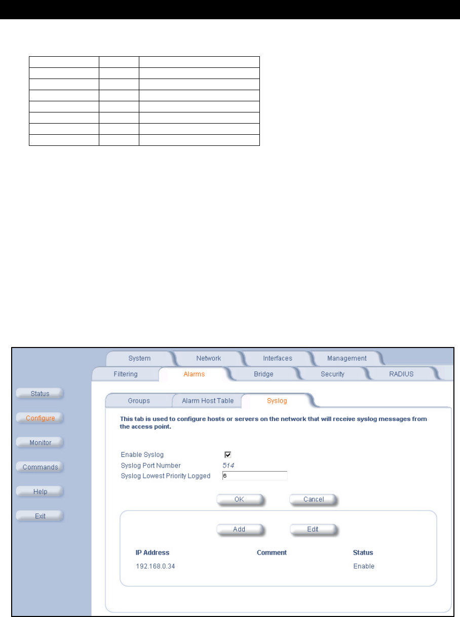
Advanced Configuration
56
Event Priority Description
Configuring Syslog Event Notifications
You can configure the following Syslog settings from the HTTP interface:
•Enable Syslog: Place a check mark in the box provided to enable system logging.
•Syslog Port Number: This field is read-only and displays the port number (514) assigned for system logging.
•Syslog Lowest Priority Logged: The AP-600 will send event messages to the Syslog server that correspond to
the selected priority and above. For example, if set to 6, the AP-600 will transmit event messages labeled priority 0
to 6 to the Syslog server(s).
•Syslog Host Table: This table specifies the IP addresses of a network servers that the AP-600 will send Syslog
messages to. Click Add to create a new entry. Click Edit to change an existing entry. Each entry contains the
following field:
–IP Address: Enter the IP Address for the management host.
–Comment: Enter an optional comment such as the host name.
–Status: The entry is enabled automatically when saved (so the Status field is only visible when editing an
entry). You can also disable or delete entries by changing this field’s value.
Figure 4-14 Syslog Configuration Screen
LOG_EMERG 0 system is unusable
LOG_ALERT 1 action must be taken immediately
LOG_CRIT 2 critical conditions
LOG_ERR 3 error conditions
LOG_WARNING 4 warning conditions
LOG_NOTICE 5 normal but significant condition
LOG_INFO 6 informational
LOG_DEBUG 7 debug-level messages

Advanced Configuration
57
Bridge
The AP-600 is a bridge between your wired and wireless networking devices. As a bridge, the functions performed by
the AP-600 include:
•MAC address learning
•Forward and filtering decision making
•Spanning Tree protocol used for loop avoidance
Once the AP-600 is connected to your network, it learns which devices are connected to it and records their MAC
addresses in the Learn Table. The table can hold up to 10,000 entries. To view the Learn Table, click on the Monitor
button in the web interface and select the Learn Table tab.
The Bridge tab has four sub-categories.
–Spanning Tree
–Storm Threshold
–Intra BSS
–Packet Forwarding
Spanning Tree
A Spanning Tree is used to avoid redundant communication loops in networks with multiple bridging devices. Bridges
do not have any inherent mechanism to avoid loops, because having redundant systems is a necessity in certain
networks. However, redundant systems can cause Broadcast Storms, multiple frame copies, and MAC address table
instability problems.
Complex network structures can create multiple loops within a network. The Spanning Tree configuration blocks
certain ports on AP-600 devices to control the path of communication within the network, avoiding loops and following
a spanning tree structure.
For more information on Spanning Tree protocol, please see Section 8.0 of the IEEE 802.1d standard. The Spanning
Tree configuration options are advanced settings. Proxim recommends that you leave these parameters at their
default values unless you are familiar with the Spanning Tree protocol.
Storm Threshold
Storm Threshold is an advanced Bridge setup option that you can use to protect the network against data overload by:
•Specifying a maximum number of frames per second as received from a single network device (identified by its
MAC address).
•Specifying an absolute maximum number of messages per port.
The Storm Threshold parameters allow you to specify a set of thresholds for each port of the AP-600, identifying
separate values for the number of broadcast messages/second and Multicast messages/second.
When the number of frames for a port or identified station exceeds the maximum value per second, the AP-600 will
ignore all subsequent messages issued by the particular network device, or ignore all messages of that type.
–Address Threshold: Enter the maximum allowed number of packets per second.
–Ethernet Threshold: Enter the maximum allowed number of packets per second.
–Wireless Threshold: Enter the maximum allowed number of packets per second.
Intra BSS
The wireless clients (or
subscribers
) that associate with a certain AP-600 form the Basic Service Set (BSS) of a
network infrastructure. By default, wireless subscribers in the same BSS can communicate with each other. However,
some administrators (such as wireless public spaces) may wish to block traffic between wireless subscribers that are
associated with the same AP-600 to prevent unauthorized communication and to conserve bandwidth. This feature
enables you to prevent wireless subscribers within a BSS from exchanging traffic.
Although this feature is generally enabled in public access environments, Enterprise LAN administrators use it to
conserve wireless bandwidth by limiting communication between wireless clients. For example, this feature prevents
peer-to-peer file sharing or gaming over the wireless network.
To block Intra BSS traffic, set Intra BSS Traffic Operation to Block.
To allow Intra BSS traffic, set Intra BSS Traffic Operation to Passthru.

Advanced Configuration
58
Packet Forwarding
The Packet Forwarding feature enables you to redirect traffic generated by wireless clients that are all associated to
the same AP-600 to a single MAC address. This filters wireless traffic without burdening the AP-600 and provides
additional security by limiting potential destinations or by routing the traffic directly to a firewall. You can redirect to a
specific port (Ethernet or WDS) or allow the bridge’s learning process (and the forwarding table entry for the selected
MAC address) to determine the optimal port.
The gateway to which traffic will be redirected should be node on the Ethernet network. It should not be a
wireless client.
Configuring Interfaces for Packet Forwarding
Configure your AP-600 to forward packets by specifying interface port(s) to which packets are redirected and a
destination MAC address.
1. Within the
Packet Forwarding Configuration
screen, check the box labeled Enable Packet Forwarding.
2. Specify a destination Packet Forwarding MAC Address. The AP-600 will redirect all unicast, multicast, and
broadcast packets received from wireless clients to the address you specify.
3. Select a Packet Forwarding Interface Port from the drop-down menu. You can redirect traffic to:
–Ethernet
–A WDS connection (see Wireless Distribution System (WDS) for details)
–Any (traffic is redirected to a port based on the bridge learning process)
4. Click OK to save your changes.
Security
The AP-600 provides three security features to protect your network from unauthorized individuals.
–MAC Access
–WEP Encryption
–802.1x
The HTTP interface provides a configuration screen for each of these features.
MAC Access
The MAC Access tab allows you to build a list of stations, identified by their MAC addresses, authorized to access the
network through the AP-600. The list is stored inside each AP-600 within your network. Note that you must reboot the
AP-600 for any changes to the MAC Access Control Table to take effect.
•Enable MAC Access Control: Check this box to enable the Control Table.
•Operation Type: Choose between Passthru and Block. This determines how the stations identified in the MAC
Access Control Table are filtered.
•If set to Passthru, only the addresses listed in the Control Table will pass through the bridge.
•If set to Block, the bridge will block traffic to or from the addresses listed in the Control Table.
•MAC Access Control Table: Click Add to create a new entry. Click Edit to change an existing entry. Each entry
contains the following field:
–MAC Address: Enter the wireless client’s MAC address.
–Comment: Enter an optional comment such as the client’s name.
•Status: The entry is enabled automatically when saved (so the Status field is only visible when editing an
entry). You can also disable or delete entries by changing this field’s value.
For larger networks that include multiple Access Points, you may prefer to maintain this list on a centralized
location using the MAC Access Control Via RADIUS Authentication.
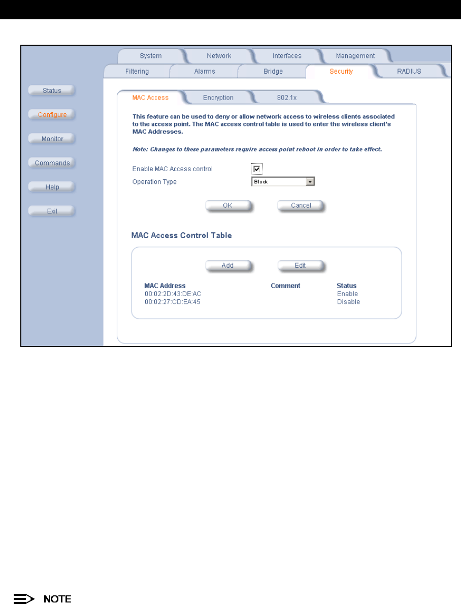
Advanced Configuration
59
Figure 4-15 MAC Access Configuration Screen
WEP Encryption
The IEEE 802.11 standards specify an optional encryption feature, known as Wired Equivalent Privacy or WEP, that is
designed to provide a wireless LAN with a security level equal to what is found on a wired Ethernet network. WEP
encrypts the data portion of each packet exchanged on an 802.11 network using an Encryption Key (also known as a
WEP Key).
When Encryption is enabled, two 802.11 devices must have the same Encryption Keys and both devices must be
configured to use Encryption in order to communicate. If one device is configured to use Encryption but a second
device is not, then the two devices will not communicate, even if both devices have the same Encryption Keys.
•The AP-600b supports 64-bit and 128-bit encryption:
–For 64-bit encryption, an encryption key is 10 hexadecimal characters (0-9 and A-F) or 5 ASCII characters
(see ASCII Character Chart).
–For 128-bit encryption, an encryption key is 26 hexadecimal characters or 13 ASCII characters.
•The AP-600a supports 64-bit, 128-bit, and 152-bit encryption:
–For 64-bit encryption, an encryption key is 10 hexadecimal characters (0-9 and A-F) or 5 ASCII characters
(see ASCII Character Chart).
–For 128-bit encryption, an encryption key is 26 hexadecimal characters or 13 ASCII characters.
–For 152-bit encryption, an encryption key is 32 hexadecimal characters or 16 ASCII characters.
64-bit encryption is sometimes referred to as 40-bit encryption; 128-bit encryption is sometimes referred to as
104-bit encryption.
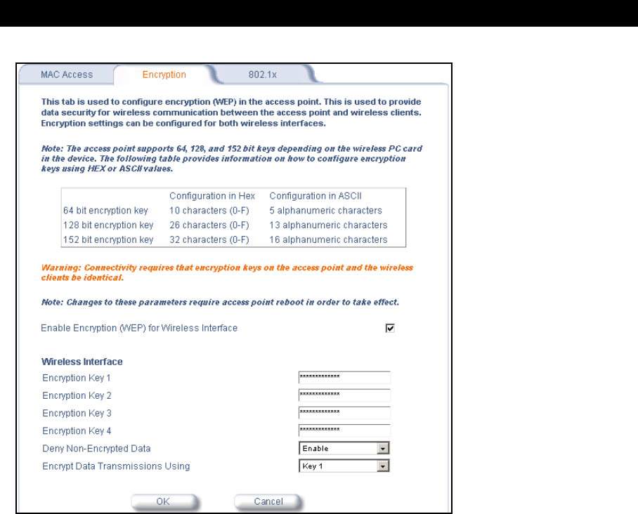
Advanced Configuration
60
Figure 4-16 Encryption Configuration
Follow these steps to set up WEP encryption on an AP-600:
1. Place a check mark in the box labeled Enable Encryption (WEP).
2. Enter one to four Encryption Keys in the fields provided. Keep in mind the following:
•If entering more than one Key, use the same number of characters for each Key. All Keys need to be the same
Key Size (64, 128, or 152-bit).
•You can enter the Encryption Keys in either hexadecimal or ASCII format.
•You need to configure your wireless clients to use the same Keys in order for the clients and the AP-600 to
communicate.
3. Set Deny Non-Encrypted Data to Enable if you want to prevent clients that do not have WEP enabled or the
proper keys configured from communicating with the network.
4. Select the Key that the AP-600 will use to encryption outgoing data from the Encrypt Data Transmissions Using
drop-down menu. By default, this parameter is set to Key 1.
5. Click OK.
802.1x
IEEE 802.1x is a standard that provides a means to authenticate and authorize network devices attached to a LAN
port. A port in the context of IEEE 802.1x is a point of attachment to the LAN, either a physical Ethernet connection or
a wireless link to an Access Point. 802.1x requires a RADIUS server and uses the Extensible Authentication Protocol
(EAP) as a standards-based authentication framework, and supports automatic key distribution for enhanced security.
The EAP-based authentication framework can easily be upgraded to keep pace with future EAP types.
Popular EAP types include:
•EAPoL (EAP over LAN): Transport protocol used to negotiate the wireless user’s secure connection to the
network. EAP messages are encapsulated in 802.1x messages.
•EAP-Message Digest 5 (MD5): Username/Password-based authentication; does not support automatic key
distribution
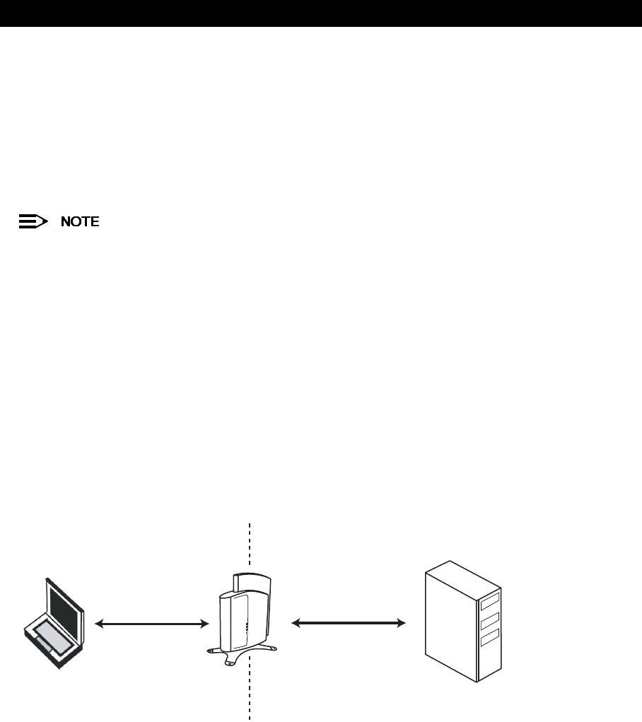
Advanced Configuration
61
•EAP-Transport Layer Security (TLS): Certificate-based authentication (a certificate is required on the server and
each client); supports automatic key distribution
•EAP-Tunneled Transport Layer Security (TTLS): Certificate-based authentication (a certificate is required on the
server; a client’s username/password is tunneled to the server over a secure connection); supports automatic key
distribution
•PEAP - Protected EAP with MS-CHAP v2: Secure username/password-based authentication; supports automatic
key distribution
Different servers support different EAP types and each EAP type provides different features. Refer to the
documentation that came with your RADIUS server to determine which EAP types it supports.
The AP-600 supports the following EAP types when 802.1x Security Mode is set to 802.1x: EAP-TLS, PEAP,
and EAP-TTLS. When 802.1x Security Mode is set to Mixed, the AP-600 supports the following EAP types:
EAP-TLS, PEAP, EAP-TLLS, and EAP-MD5 (MD5 does not support automatic key distribution; therefore, if
you choose this method you need to manually configure each client with the network’s encryption key).
Authentication Process
There are three main components in the authentication process. The standard refers to them as:
1. supplicant (client PC)
2. authenticator (Access Point)
3. authentication server (RADIUS server)
When using 802.1x Security Mode or Mixed mode (802.1x and WEP), you need to configure your RADIUS server for
authentication purposes.
Prior to successful authentication, an unauthenticated client PC cannot send any data traffic through the AP-600
device to other systems on the LAN. The AP-600 inhibits all data traffic from a particular client PC until the client PC is
authenticated. Regardless of its authentication status, a client PC can always exchange 802.1x messages in the clear
with the AP-600 (the client begins encrypting data after it has been authenticated).
Figure 4-17 RADIUS Authentication Illustrated
The AP-600 acts as a pass-through device to facilitate communications between the client PC and the RADIUS server.
The AP-600 and the client exchange 802.1x messages using an EAPOL (EAP Over LAN) protocol. Messages sent
from the client station are encapsulated by the AP-600 and transmitted to the RADIUS server using EAP extensions.
Upon receiving a reply EAP packet from the RADIUS, the message is typically forwarded to the client, after translating
it back to the EAPOL format. Negotiations take place between the client and the RADIUS server. After the client has
been successfully authenticated, the client receives an Encryption Key from the AP-600 (if the EAP type supports
automatic key distribution). The client uses this key to encrypt data after it has been authenticated.
For 802.11a clients that communicate with an AP-600a, each client receives its own unique encryption key; this is
known as Per User Per Session Encryption Keys. (This feature is only available when using 802.1x mode; it is not
available when in Mixed mode or using WEP encryption only).
PC Client Access Point
RADIUS Server
EAP Over Wireless EAP Over RADIUS
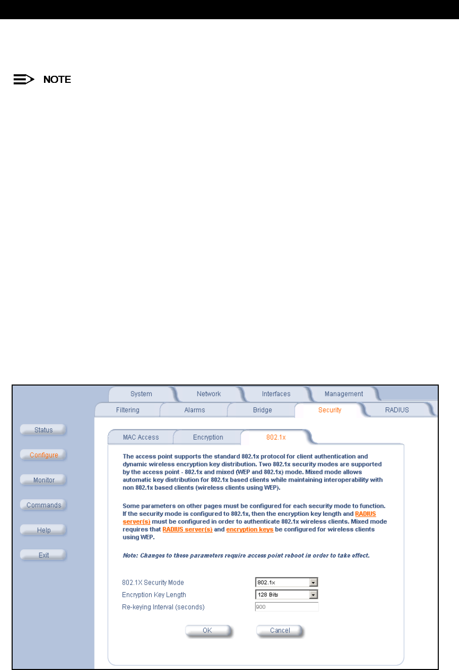
Advanced Configuration
62
Configuring Security Settings
The AP-600 offers four security settings:
802.1x settings are located under the
802.1x
heading. WEP Encryption settings are located under the
Encryption
heading.
•No security or encryption
•WEP encryption only
–See WEP Encryption for details.
•802.1x security
•Mixed Mode (802.1x and WEP Encryption)
802.1x Security
Follow these steps to enable 802.1x only:
1. Within the
802.1x Configuration
screen, set 802.1x Security Mode to 802.1x.
2. Select an Encryption Key Length.
•The AP-600b supports 64-bit and 128-bit encryption.
•The AP-600a supports 64-bit, 128-bit, and 152-bit encryption.
3. Enter a Re-keying Interval.
•The Re-keying Interval determines how often a client’s encryption key is changed and can be set to any value
between 60 - 65535 seconds. Rekeying frustrates hacking attempts without taxing system resources. Setting
a fairly frequent rekey value (900 seconds=15 minutes) effectively protects against intrusion without disrupting
network activities.
4. Click OK to save the changes.
5. If you have not already done so, configure the RADIUS authentication settings (see RADIUS Authentication with
802.1x for details.
6. Reboot the Access Point.
Figure 4-18 802.1x Configuration Screen

Advanced Configuration
63
Mixed Mode (802.1x and WEP Encryption)
Follow these steps to use both 802.1x and WEP Encryption simultaneously (clients that do not support 802.1x use
WEP Encryption for security purposes):
1. Within the
802.1x Configuration
screen, set 802.1x Security Mode to Mixed.
2. Select an Encryption Key Length.
•The AP-600b supports 64-bit and 128-bit encryption.
•The AP-600a supports 64-bit, 128-bit, and 152-bit encryption.
3. Enter a Re-keying Interval.
•The Re-keying Interval determines how often a client’s encryption key is changed and can be set to any value
between 60 - 65535 seconds. Rekeying frustrates hacking attempts without taxing system resources. Setting
a fairly frequent rekey value (900 seconds=15 minutes) effectively protects against intrusion without disrupting
network activities.
4. Click OK to save the changes.
5. Click the Encryption tab.
1. Place a check mark in the box labeled Enable Encryption (WEP).
2. Configure Encryption Key 1 only (i.e., do not configure Keys 2 through 4). Keep in mind the following:
•Use the same key size (64/128/152-bit) that you configured for Encryption Key Length on the 802.1x page.
—For 64-bit encryption, an encryption key is 10 hexadecimal characters (0-9 and A-F) or 5 ASCII
characters (see ASCII Character Chart).
—For 128-bit encryption, an encryption key is 26 hexadecimal characters or 13 ASCII characters.
—For 152-bit encryption, an encryption key is 32 hexadecimal characters or 16 ASCII characters.
•You can enter the Encryption Keys in either hexadecimal or ASCII format.
•You need to manually configure your wireless clients that do not support 802.1x to use the same Encryption
Key.
3. Set Deny Non-Encrypted Data to Enable if you want to prevent clients that do not have WEP enabled or the
proper keys configured from communicating with the network.
4. Confirm that Key 1 is selected in the Encrypt Data Transmissions Using drop-down menu.
5. Click OK.
6. If you have not already done so, configure the RADIUS authentication settings (see RADIUS Authentication with
802.1x for details.
7. Reboot the Access Point.
802.1x Security and Wireless Distribution Systems (WDS)
Wireless distribution systems (WDS) are configured using specific ports on the AP-600b. To use 802.1x with WDS, you
need to set the 802.1x Security Mode to Mixed (WEP and 802.1x) and confirm that the AP-600b units communicating
in the WDS share the same encryption key (Key 1). See Wireless Distribution System (WDS) for more information.
The AP-600a does not support WDS.
RADIUS
The AP-600 communicates with a network’s RADIUS server to provide the following features:
–MAC Access Control Via RADIUS Authentication
–RADIUS Authentication with 802.1x
–RADIUS Accounting
You can configure the AP-600 to communicate with up to four different RADIUS servers:
•Primary Authentication Server
•Back-up Authentication Server
•Primary Accounting Server
•Back-up Accounting Server
You must have configured the settings for at least one Authentication server before configuring the settings for
an Accounting server.

Advanced Configuration
64
The back-up servers are optional, but when configured, the AP-600 will communicate with the back-up server if the
primary server is off-line. After the AP-600 has switched to the backup server, it will periodically check the status of the
primary RADIUS server every five (5) minutes. Once the primary RADIUS server is again online, the AP-600
automatically reverts from the backup RADIUS server back to the primary RADIUS server. All subsequent requests
are then sent to the primary RADIUS server.
MAC Access Control Via RADIUS Authentication
If you want to control wireless access to the network and if your network includes a RADIUS Server, you can store the
list of MAC addresses on the RADIUS server rather than configure each AP-600 individually. From the RADIUS
Authentication tab, you can define the IP Address of the server that contains a central list of MAC Address values that
identify the authorized stations that may access the wireless network. You must specify information for at least the
primary RADIUS server. The back-up RADIUS server is optional.
Contact your RADIUS server manufacturer if you have problems configuring the server or have problems
using RADIUS authentication.
Follow these steps to enable RADIUS MAC Access Control:
1. Within the
RADIUS Access Control Configuration
screen, place a check mark in the box labeled Enable
RADIUS MAC Access Control.
2. Place a check mark in the box labeled Enable Primary RADIUS Authentication Server.
3. If you want to configure a back-up RADIUS server, place a check mark in the box labeled Enable Back-up
RADIUS Authentication Server.
4. Enter the time, in seconds, each client session may be active before being automatically re-authenticated in the
Authentication Lifetime field. This parameter supports a value between 60 and 43200 sec; the default is 900 sec.
5. Select a MAC Address Format Type. This should correspond to the format in which the clients’ 12-digit MAC
addresses are listed within the RADIUS server. Available options include:
•Dash delimited: dash between each pair of digits: xx-yy-zz-aa-bb-cc
•Colon delimited: colon between each pair of digits: xx:yy:zz:aa:bb:cc)
•Single dash delimited: dash between the sixth and seventh digits: xxyyzz-aabbcc
•No delimiters: No characters or spaces between pairs of hexadecimal digits: xxyyzzaabbcc
6. Select a Server Addressing Format type (IP Address or Name).
•If you want to identify RADIUS servers by name, you must configure the AP-600 as a DNS Client. See DNS
Client for details.
7. Enter the server’s IP address or name in the field provided.
8. Enter the port number which the AP-600 and the server will use to communicate. By default, RADIUS servers
communicate on port 1812.
9. Enter the Shared Secret in the Shared Secret and Confirm Shared Secret field. This is a password shared by the
RADIUS server and the AP-600. The same password must also be configured on the RADIUS server.
10. Enter the maximum time, in seconds, that the AP-600 should wait for the RADIUS server to respond to a request in
the Response Time field. Range is 1-10 seconds; default is 3 seconds.
11. Enter the maximum number of times an authentication request may be retransmitted in the Maximum
Retransmissions field. Range is 1-4; default is 3.
12. If you are configuring a back-up server, repeat Steps 6 through 11 for the back-up server.
13. Click OK to save your changes.
14. Reboot the AP-600 device for these changes to take effect.
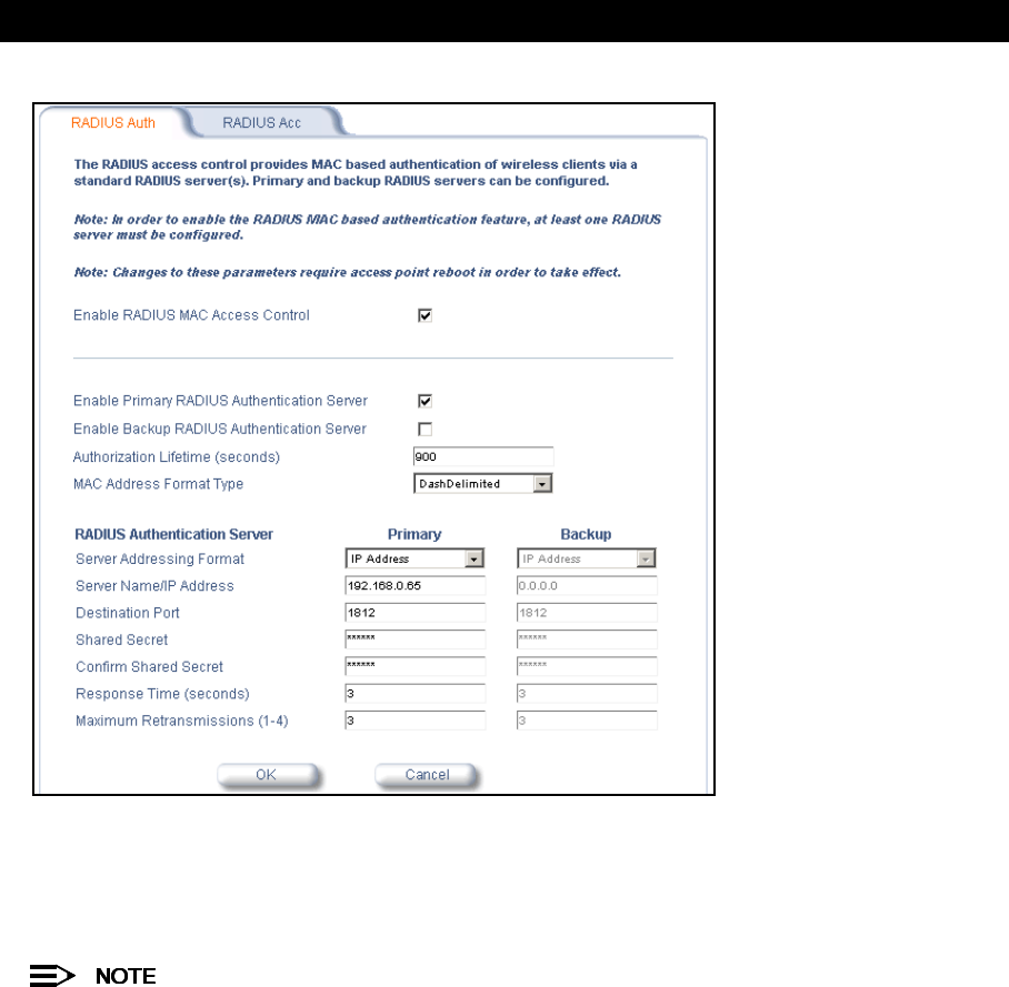
Advanced Configuration
65
Figure 4-19 RADIUS Access Control Configuration Screen
RADIUS Authentication with 802.1x
You must configure a primary RADIUS Authentication server to use 802.1x security. A back-up server is optional.
Problems with RADIUS Server configuration or RADIUS Authentication should be referred to the RADIUS
Server developer.
Follow these steps to enable a RADIUS Authentication server for 802.1x security:
1. Within the
802.1x Configuration
screen, configure the 802.1x settings. See 802.1x for details.
2. Click the RADIUS tab.
3. Click the RADIUS Auth sub-tab.
4. Place a check mark in the box labeled Enable Primary RADIUS Authentication Server.
5. If you want to configure a back-up RADIUS server, place a check mark in the box labeled Enable Back-up
RADIUS Authentication Server.
6. Enter the time, in seconds, each client session may be active before being automatically re-authenticated in the
Authentication Lifetime field. This parameter supports a value between 60 and 43200 sec; the default is 900 sec.
7. Select a Server Addressing Format type (IP Address or Name).
•If you want to identify RADIUS servers by name, you must configure the AP-600 as a DNS Client. See DNS
Client for details.
8. Enter the server’s IP address or name in the field provided.
9. Enter the port number which the AP-600 and the server will use to communicate. By default, RADIUS servers
communicate on port 1812.
10. Enter the Shared Secret in the Shared Secret and Confirm Shared Secret field. This is a password shared by the
RADIUS server and the AP-600. The same password must also be configured on the RADIUS server.
11. Enter the maximum time, in seconds, that the AP-600 should wait for the RADIUS server to respond to a request in
the Response Time field. Range is 1-10 seconds; default is 3 seconds.

Advanced Configuration
66
12. Enter the maximum number of times an authentication request may be retransmitted in the Maximum
Retransmissions field. Range is 1-4; default is 3.
13. If you are configuring a back-up server, repeat Steps 7 through 12 for the back-up server.
14. Click OK to save your changes.
15. Reboot the AP-600 device for these changes to take effect.
RADIUS Accounting
Using an external RADIUS server, the AP-600 can track and record the length of client sessions on the access point by
sending RADIUS accounting messages per RFC2866. When a wireless client is successfully authenticated, RADIUS
accounting is initiated by sending an “Accounting Start” request to the RADIUS server. When the wireless client
session ends, an “Accounting Stop” request is sent to the RADIUS server.
Session Length
Accounting sessions continue when a client reauthenticates to the same AP-600. Sessions are terminated when:
•A client disassociates.
•A client does not transmit any data to the AP-600 for a fixed amount of time.
•A client is detected on a different interface.
If the client roams from one AP-600 to another, one session is terminated and a new session is begun.
This feature requires RADIUS authentication using MAC Access Control or 802.1x. Wireless clients
configured in the Access Point’s static MAC Access Control list are not tracked.
Configuring RADIUS Accounting
Follow these steps to enable RADIUS accounting on the AP-600:
1. Within the
RADIUS Accounting Configuration
screen, place a check mark in the Enable RADIUS Accounting
box to turn on this feature.
2. Place a check mark in the box labeled Enable Primary RADIUS Accounting Server.
3. If you want to configure a back-up RADIUS server, place a check mark in the box labeled Enable Back-up
RADIUS Accounting Server.
4. Enter the session timeout interval in minutes within the Accounting Inactivity Timer field. An accounting session
automatically ends for a client that is idle for the period of time specified. Range is 1-60 minutes; default is
5 minutes.
5. Select a Server Addressing Format type (IP Address or Name).
•If you want to identify RADIUS servers by name, you must configure the Access Point as a DNS Client. See
DNS Client for details.
6. Enter the server’s IP address or name in the field provided.
7. Enter the port number which the AP-600 and the server will use to communicate. By default, RADIUS accounting
uses port 1813.
8. Enter the Shared Secret in the Shared Secret and Confirm Shared Secret field. This is a password shared by the
RADIUS server and the AP-600. The same password must also be configured on the RADIUS server.
9. Enter the maximum time, in seconds, that the AP-600 should wait for the RADIUS server to respond to a request in
the Response Time field. Range is 1-10 seconds; default is 3 seconds.
10. Enter the maximum number of times an authentication request may be retransmitted in the Maximum
Retransmissions field. Range is 1-4; default is 3.
11. If you are configuring a back-up server, repeat Steps 5 through 10 for the back-up server.
12. Click OK to save your changes.
13. Reboot the AP-600 device for these changes to take effect.
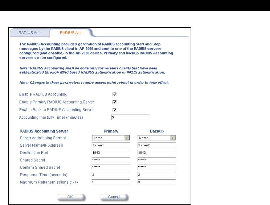
Advanced Configuration
67
Figure 4-20 RADIUS Accounting Server Configuration

Advanced Configuration
68

Advanced Configuration
69

Advanced Configuration
70

68
5
Monitor Information
In This Chapter
This chapter describes the statistical information that is reported within the Access Point’s HTTP interface.
•Logging into the HTTP Interface
•Version: Provides version information for the Access Point’s system components.
•ICMP: Displays statistics for Internet Control Message Protocol packets sent and received by the AP-600.
•IP/ARP Table: Displays the AP-600’s IP Address Resolution table.
•Learn Table: Displays the list of nodes that the AP-600 has learned are on the network.
•IAPP: Provides statistics for the Inter-Access Point Protocol messages sent and received by the AP-600.
•RADIUS: Provides statistics for the configured primary and backup RADIUS server(s).
•Interfaces: Displays the Access Point’s interface statistics (Wireless and Ethernet).
•Link Test (AP-600b Only): Evaluates the link with a wireless client.
Logging into the HTTP Interface
Once the AP-600 has a valid IP Address and an Ethernet connection, you may use your web browser to monitor
network statistics.
The Command Line Interface (CLI) also provides a method for viewing network statistics using Telnet or a serial
connection. This section covers only use of the HTTP interface. For more information about viewing network statistics
with the CLI, refer to Command Line Interface (CLI).
Follow these steps to monitor an AP-600’s operating statistics using the HTTP interface:
1. Open a Web browser on a network computer.
The HTTP interface supports the following Web browser:
•Microsoft Internet Explorer 5.5 or later
•Netscape 4.x or later
2. If necessary, disable the Internet proxy settings. For Internet Explorer users, follow these steps:
–Select Tools > Internet Options....
–Click the Connections tab.
–Click LAN Settings....
–If necessary, remove the check mark from the Use a proxy server box.
–Click OK twice to save your changes and return to Internet Explorer.
3. Enter the Access Point’s IP address in the browser’s Address field and press Enter.
–Result: The AP-600
Enter Network Password
screen appears.
4. Enter the HTTP password in the Password field and click OK. Leave the User Name field blank. (By default, the
HTTP password is “public”).
–Result: The
System Status
screen appears.
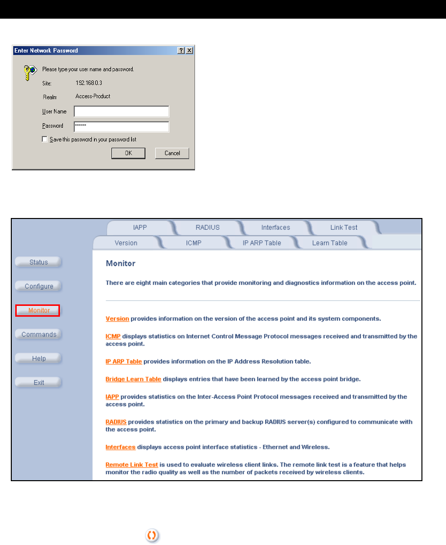
Monitor Information
69
Figure 5-1 Enter Network Password Screen
5. Click the Monitor button located on the left-hand side of the screen.
Figure 5-2 Monitor Main Screen
6. Click the tab that corresponds to the statistics you want to review. For example, click Learn Table to see the list of
nodes that the AP-600 has discovered on the network.
7. If applicable, click the Refresh button to update the statistics.
Version
From the HTTP interface, click the Monitor button and select the Version tab. The list displayed provides you with
information that may be pertinent when calling Technical Support. With this information, your Technical Support
representative can verify compatibility issues and make sure the latest software are loaded. This screen displays the
following information for each Access Point component:
•Serial Number: The component’s serial number, if applicable.
•Component Name
•ID: The AP-600 identifies a system component based on its ID. Each component has a unique identifier.
•Variant: Several variants may exist of the same component (for example, a hardware component may have two
variants, one with more memory than the other).
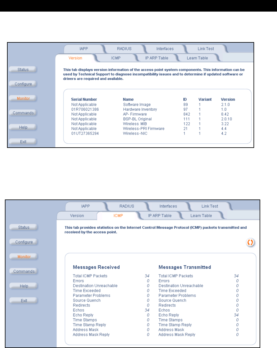
Monitor Information
70
•Version: Specifies the component’s version or build number. The Software Image version is the most useful
information on this screen for the typical end user.
Figure 5-3 Version Information Screen
ICMP
This tab provides statistical information for both received and transmitted messages directed to the AP-600. Not all
ICMP traffic on the network is counted in the ICMP (Internet Control Message Protocol) statistics.
Figure 5-4 ICMP Monitoring Screen
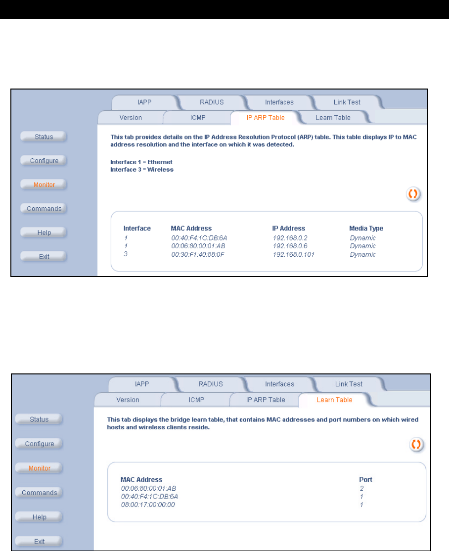
Monitor Information
71
IP/ARP Table
This tab provides information based on the Address Resolution Protocol (ARP), which relates MAC Address and IP
Addresses.
Figure 5-5 IP/ARP Table
Learn Table
This tab displays information relating to network bridging. It reports the MAC address for each node that the device has
learned is on the network and the interface on which the node was detected. There can be up 10,000 entries in the
Learn Table.
Figure 5-6 Learn Table
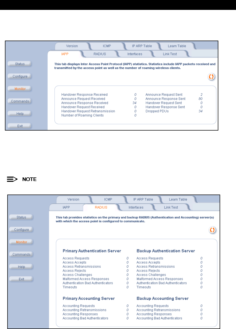
Monitor Information
72
IAPP
This tab displays statistics relating to client handovers and communications between ORiNOCO Access Points.
Figure 5-7 IAPP Screen
RADIUS
This tab provides RADIUS authentication and accounting information for both the Primary and Backup RADIUS
servers.
RADIUS authentication and accounting must be enabled for this information to be valid.
Figure 5-8 RADIUS Monitoring Screen
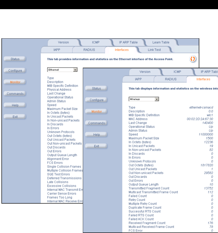
Monitor Information
73
Interfaces
This tab displays statistics for the Ethernet and wireless interfaces. The Operational Status can be up, down, or testing.
Figure 5-9 Wireless Interface Monitoring
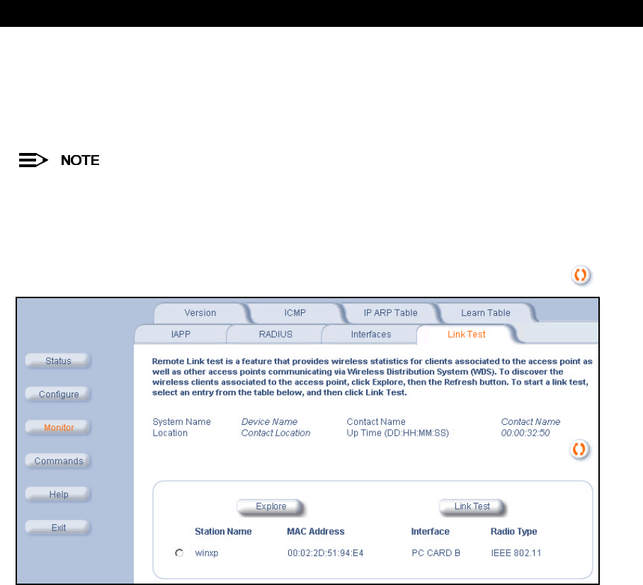
Monitor Information
74
Link Test (AP-600b Only)
This tab displays information on the quality of the wireless link to clients and other AP-600b units in the Wireless
Distribution System. During a Link Test, the Access Point and the selected device exchange a series of packets to test
the strength of the connection. The devices start by exchanging packets at the 11 Mbits/sec rate but fall back to the
slower rates if necessary.
This feature is not available for the AP-600a. Also, this feature is not available if you are using an ORiNOCO
802.11a/b ComboCard or a non-ORiNOCO client with the AP-600b.
Follow these steps to perform a Link Test:
1. Open the
Remote Link Test
screen.
2. Click Explore.
Result: A list of detected stations will appear. If the list does not appear automatically, click Refresh .
Figure 5-10 Remote Link Test Screen
3. Select a Station from the list by clicking the circle to the left of the Station’s entry.
4. Click Link Test to start the test.
Result: A new Link Test window opens and displays the following information for the Access Point (referred to as
the Initiator Station) and the wireless client (referred to as the Remote Station):
•Station Name: The Access Point’s System Name or the client’s Windows Networking name.
•MAC Address
•SNR (dB): The Signal to Noise ratio for the received signal. The displayed value is the running average since
the start of the test and is reported in decibels (dB). Higher numbers correspond to a stronger link. The bar
graph also displays the relative strength of the link (a green bar indicates a strong link, a yellow bar indicates a
fair link, and a red bar indicates a weak link).
•Signal (dBm): The strength of the received signal in dBm (decibels referenced to 1 milliwatt). The displayed
value is the running average since the start of the test and is reported as a negative number. Higher numbers
correspond to a stronger link. For example, -40 dBm corresponds to a stronger signal than -50 dBm. The bar
graph also displays the relative strength of the signal (a longer bar represents a stronger signal).
•Noise (dBm): The strength of the noise detected at the receiver reported in dBm (decibels referenced to
1 milliwatt). The displayed value is the running average since the start of the test and is reported as a negative
number. Noise can interfere with the received signal so a smaller noise value corresponds to a stronger link.
For example, a noise level of -95 dBm is more desirable than a noise level of -89 dBm. The bar graph displays
the relative strength of the noise level (a shorter bar represents a weaker noise level and is more desirable
than a longer bar).
•11 Mbps (pkts): The number of packets received at the 11 Mbits/sec transmit rate since the start of the Link
Test. In general, most packets will be received at the 11 Mbits/sec rate if the devices have a strong link.
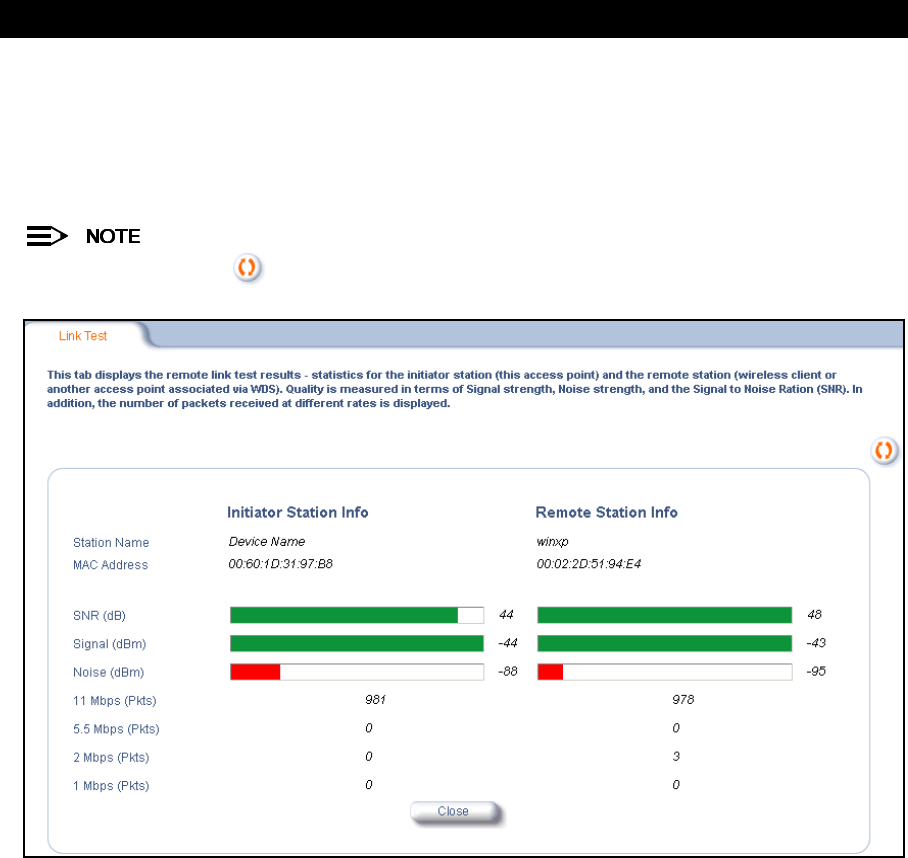
Monitor Information
75
•5.5 Mbps (pkts): The number of packets received at the 5.5 Mbits/sec transmit rate since the start of the Link
Te s t .
•2 Mbps (pkts): The number of packets received at the 2 Mbits/sec transmit rate since the start of the Link
Te s t .
•1 Mbps (pkts): The number of packets received at the 1 Mbits/sec transmit rate since the start of the Link
Te s t .
Click the Refresh button periodically to update the test results. The test screen does not refresh
automatically.
Figure 5-11 SNR Report Screen
5. Click Close to end the Link Test.

Monitor Information
76

Monitor Information
77

76
6
Commands
In This Chapter
This chapter describes the commands that can be issued from the Access Point’s HTTP interface.
•Logging into the HTTP Interface
•Download: Download files from a TFTP server to the AP-600.
•Upload: Upload configuration files from the AP-600 to a TFTP server.
•Reboot: Reboot the AP-600 in the specified number of seconds.
•Reset: Reset all of the Access Point’s configuration settings to factory defaults.
•Help Link: Configure the location where the AP-600 Help files can be found.
Logging into the HTTP Interface
Once the AP-600 has a valid IP Address and an Ethernet connection, you may use your web browser to issue
commands.
The Command Line Interface (CLI) also provides a method for issuing commands using Telnet or a serial connection.
This section covers only use of the HTTP Interface. For more information about issuing commands with the CLI, refer
to Command Line Interface (CLI).
Follow these steps to view the available commands supported by the AP-600’s HTTP interface:
1. Open a Web browser on a network computer.
The HTTP interface supports the following Web browser:
•Microsoft Internet Explorer 5.5 or later
•Netscape 4.x or later
2. If necessary, disable the Internet proxy settings. For Internet Explorer users, follow these steps:
–Select Tools > Internet Options....
–Click the Connections tab.
–Click LAN Settings....
–If necessary, remove the check mark from the Use a proxy server box.
–Click OK twice to save your changes and return to Internet Explorer.
3. Enter the Access Point’s IP address in the browser’s Address field and press Enter.
–Result: The
Enter Network Password
screen appears.
4. Enter the HTTP password in the Password field and click OK. Leave the User Name field blank. (By default, the
HTTP password is “public”).
–Result: The
System Status
screen appears.
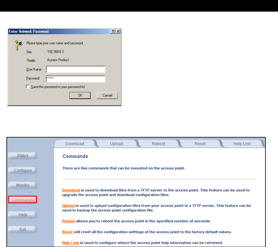
Commands
77
Figure 6-1 Enter Network Password Screen
5. Click the Commands button located on the left-hand side of the screen.
Figure 6-2 Commands Main Screen
6. Click the tab that corresponds to the command you want to issue. For example, click Reboot to restart the unit.
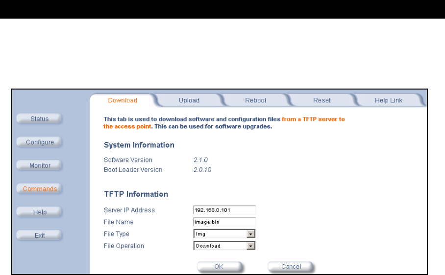
Commands
78
Download
Use the Download tab to download Configuration, AP Image, and Bootloader files to the AP-600. A TFTP server must
be running and configured to point to the directory containing the file.
Figure 6-3 Download Command Screen
If you don’t have a TFTP server installed on your system, install the TFTP server from the ORiNOCO CD. You can
either install the TFTP server from the CD Wizard or run OEM-TFTP-Server.exe found in the CD’s
Xtras/SolarWinds
sub-directory.
The Download tab shows version information and allows you to enter TFTP information as described below.
•Server IP Address: Enter the TFTP server IP Address.
–Double-click the TFTP server icon on your desktop and locate the IP address assigned to the TFTP server.
Note: This is the IP address that will be used to point the Access Point to the AP Image file.
•File Name: Enter the name of the file to be downloaded (including the file extension).
–Copy the updated AP Image file to the TFTP server’s root folder. The default AP Image is located at
C:/Program Files/ORiNOCO/AP600/
.
•File Type: Select the proper file type. Choices include:
–Config for configuration information, such as System Name, Contact Name, and so on.
–Img for the AP Image (executable program).
–BspBl for the Bootloader software.
•File Operation: Select either Download or Download & Reboot. You should reboot the AP-600 after
downloading files.
Upload
Use the Upload tab to upload Configuration files from the AP-600. The TFTP server must be running and configured
to point to the directory to which you want to copy the uploaded file. We suggest you assign the file a meaningful
name, which may include version or location information.
If you don’t have a TFTP server installed on your system, install the TFTP server from the ORiNOCO CD. You can
either install the TFTP server from the CD Wizard or run OEM-TFTP-Server.exe found in the CD’s
Xtras/SolarWinds
sub-directory.
•Server IP Address: Enter the TFTP server IP Address.
–Double-click the TFTP server icon on your desktop and locate the IP address assigned to the TFTP server.
•File Name: Enter the name of the file to be uploaded.
•File Type: Select Config.
•File Operation: Select Upload.
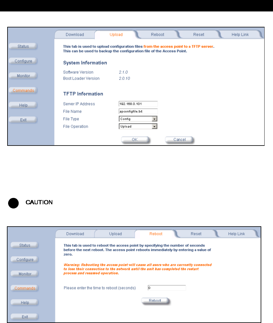
Commands
79
Figure 6-4 Upload Command Screen
Reboot
Use the Reboot tab to save configuration changes (if any) and reset the AP-600. Entering a value of 0 (zero) seconds
causes an immediate reboot. Note that Reset, described below, does not save configuration changes.
!
Rebooting the AP-600 will cause all users who are currently connected to lose their connection to the network
until the AP-600 has completed the restart process and resumed operation.
Figure 6-5 Reboot Command Screen
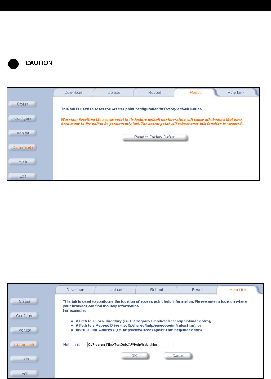
Commands
80
Reset
Use the Reset tab to restore the AP-600 to factory default conditions. The AP-600 may also be reset from the RESET
button located on the side of the unit. Since this will reset the Access Point’s current IP address, a new IP address
must be assigned. Refer to Recovery Procedures for more information.
!
Resetting the AP-600 to its factory default configuration will permanently overwrite all changes that have made
to the unit. The AP-600 will reboot automatically after this command has been issued.
Figure 6-6 Reset to Factory Defaults Command Screen
Help Link
To open Help, click the Help button on any display screen.
During initialization, the AP-600 on-line help files are downloaded to the default location:
C:\Program Files\ORiNOCO\AP600\Help\English\index.htm
.
The ORiNOCO AP-600 Help information is available in English, French, German, Italian, Spanish, and Japanese. The
Help files are copied to your computer in all six languages. To update the Help link to use a different language, enter
the appropriate path in the Help Link box. For example, to change to the French Help file, enter
C:\Program Files\ORiNOCO\AP600\Help\French\index.htm
.
If you want to place these files on a shared drive, copy the Help Folder to the new location, and then specify the new
path in the Help Link box.
Figure 6-7 Help Link Configuration Screen

81
7
Troubleshooting
In This Chapter
If you are having problems with an AP-600, review the troubleshooting suggestions contained in this chapter.
•Troubleshooting Concepts
•Symptoms and Solutions
•Recovery Procedures
•System Alarms (Traps)
•Related Applications
This section helps you locate problems related to the AP-600 device setup. For details about RADIUS, TFTP,
serial communication programs (such as HyperTerminal), Telnet applications, or web browsers, please refer to
the documentation that came with the application for assistance.
Troubleshooting Concepts
The following list identifies important troubleshooting concepts and topics. The most common initialization and
installation problems relate to IP addressing. For example, you must have valid IP addresses for both the AP-600 and
the management computer to access the unit’s HTTP interface.
•IP Address management is fundamental.
•Factory default units are set for “Dynamic” (DHCP) IP Address assignment. The default IP address for the
AP-600 is 169.254.128.132 if your network does not have a DHCP server. If you connect the AP-600 unit to a
network with an active DHCP server, then use ScanTool to locate the IP address of your unit. If a DHCP server is
not active on your subnet, then use ScanTool to assign a static IP address to the unit.
•The Trivial File Transfer Protocol (TFTP) provides a means to download and upload files. These files include
the AP-600 Image (executable program) and configuration files.
•If the AP-600 password is lost or forgotten, you will need to reset to default values. The Reset to Factory
Default Procedure resets configuration, but does not change the current AP Image.
•If all else fails… Use the Forced Reload Procedure to erase the current AP-600 Image and then download a new
image. Once the new image is loaded, use the Reset to Factory Default Procedure to set the unit to factory default
values and reconfigure the unit.
•The AP-600 Supports a Command Line Interface (CLI). If you are having trouble locating your AP-600 on the
network, connect to the unit directly using the serial interface and refer to Command Line Interface (CLI) for CLI
command syntax and parameter names.

Troubleshooting
82
Symptoms and Solutions
Connectivity Issues
Connectivity issues include any problem that prevents you from powering up or connecting to the AP-600.
AP-600 Unit Will Not Boot - No LED Activity
1. Make sure your power source is operating.
2. Make sure all cables are connected to the AP-600 correctly.
3. If you are using Active Ethernet, make sure you are using a Category 5, foiled, twisted pair cable to power the
AP-600.
Serial Link Does Not Work
1. Make sure you are using a standard, straight-through, 9-pin serial cable.
2. Double-check the physical network connections.
3. Make sure your PC terminal program (such as HyperTerminal) is active and configured to the following values:
–Com Port: (COM1, COM2, etc. depending on your computer);
–Baud rate: 9600; Data bits: 8; Stop bits: 1; Flow Control: None; Parity: None;
–Line Feeds with Carriage Returns
(In HyperTerminal select:
File -> Properties -> Settings -> ASCII Setup -> Send Line Ends with Line Feeds)
Ethernet Link Does Not Work
1. Double-check the physical network connections. Use a known-good unit to make sure the network connection is
present. Once you have the AP-600 IP address, you can use the “Ping” command over Ethernet to test the IP
Address. If the AP-600 responds to the Ping, then the Ethernet Interface is working properly.
2. By default, the Access Point will attempt to automatically detect the Ethernet settings. However, if you are having
problems with the Ethernet link, manually configure the Access Point’s Ethernet settings. For example, if your
switch operates at 100 Mbits/sec/Full Duplex, manually configure the Access Point to use these settings (see
Ethernet). If you cannot access the unit over Ethernet, then use the CLI interface over the serial port to configure
the Ethernet port (see Command Line Interface (CLI) and Set Ethernet Speed and Transmission Mode).
3. Perform network infrastructure troubleshooting (check switches, routers, etc.).
Basic Software Setup and Configuration Problems
Lost AP-600, Telnet, or SNMP Password
1. Perform the Reset to Factory Default Procedure in this guide. This procedure resets system and network
parameters, but does not affect the AP-600 Image.
The default AP-600 HTTP password is “public”, and the default Telnet password is also “public”.
Client Computer Cannot Connect
1. Client computers should have the same Network Name and security settings as the AP-600.
2. Network Names should be allocated and maintained by the Network Administrator.
3. Refer to the documentation that came with your client card for additional troubleshooting suggestions.
AP-600 Has Incorrect IP Address
1. Default IP Address Assignment mode is dynamic (DHCP). If you do not have a DHCP server on your network, the
default IP Address is 169.254.128.132. If you have more than one unintialized AP-600 connected to the network,
they will all have the same default IP address and you will not be able to communicate with them (due to an IP
address conflict). In this case, assign each AP a static IP address via the serial cable or turn off all units but one
and change the IP address using ScanTool one at a time.
2. The AP-600 only contacts a DHCP server during boot-up. If your network’s DHCP server is not available while the
AP-600 is booting, the device will retain the last IP Address it had. Reboot the AP-600 once your DHCP server is
on-line again or use the ScanTool to find the Access Point’s current IP address.

Troubleshooting
83
3. To find the unit’s current IP address if using DHCP, open the IP Client Table in the DHCP Server and match the
Access Point’s IP address to its MAC address (found on the product label). Alternatively, use ScanTool to identify
an Access Point’s current IP address.
4. Once you have the current IP address, use the HTTP or CLI Interface to change the unit’s IP settings, if necessary.
5. If you use static IP Address assignments, and cannot access the unit over Ethernet, use the Initializing the IP
Address using CLI procedure. Once the IP Address is set, you can use the Ethernet Interface to complete
configuration.
6. Perform the Reset to Factory Default Procedure in this guide. This will reset the unit to “DHCP” mode. If there is a
DHCP Server on the network, the DHCP Server will assign an IP Address to the AP-600.
HTTP (browser) or Telnet Interface Does Not Work
1. Make sure you are using a compatible browser: Microsoft Internet Explorer 5.5 or later (preferred), or Netscape 4.x
or later.
2. Make sure you have the proper IP address. Enter your Access Point’s IP Address in the browser address bar,
similar to this example:
http://192.168.1.100
When the
Enter Network Password
window appears, leave the
User Name field empty and enter the HTTP
password in the Password field. The default HTTP password is “public”.
3. Use the CLI over the serial port to check the IP Access Table, which can be restricting access to Telnet and HTTP.
HTML Help Files Do Not Appear
1. Verify that the HTML Help files are installed in the default directory:
C:\Program Files\ORiNOCO\AP600\Help\<language>
2. If the Help files are not located in this folder, contact your network administrator to find out where the Help files are
located on your server.
3. Perform the following steps to verify the location or to enter the pathname for the Help files:
a. Click the Commands button in the HTTP interface.
b. Select the Help tab located at the top of the screen.
c. Enter the pathname where the Help files are located in the Help Link box.
d. Click OK when finished.
Telnet CLI Does Not Work
1. Make sure you have the proper IP Address. Enter your AP-600 IP address in the Telnet connection dialog, from a
DOS prompt, type:
C:\> telnet <AP-600 IP Address>
2. Confirm that your computer has an IP address in the same IP subnet as your Access Point.
3. Use the CLI over the serial port to check the IP Access Table, which can be restricting access to Telnet and HTTP.
TFTP Server Does Not Work
1. Make sure the TFTP Server has been started.
2. Verify the IP address of the TFTP Server. The server may be local or remote, so long as it has a valid IP address.
3. Configure the TFTP Server to “point” to the folder containing the file to be downloaded (or to the folder in which the
file is to be uploaded).
4. Verify that you have entered the proper AP-600 Image file name (including the file extension) and directory path.
5. If you have a problem uploading a file, verify that the TFTP server is configured to allow uploads (typically the
default setting is to allow only downloads).

Troubleshooting
84
Client Connection Problems
Client Software Finds No Connection
Make sure you have configured your
client software with the proper Network Name and Security settings. Network
Names and WEP Keys are typically allocated and maintained by your network administrator.
Client PC Card Does Not Work
1. Make sure you are using the latest PC Card driver software.
2. Download and install the latest ORiNOCO
client software from http://www.proxim.com/support/.
Intermittent Loss of Connection
1. Make sure you are within range of an active AP-600.
2. You can check the signal strength using the signal strength gauge on your ORiNOCO
client software. If you are
have an AP-600b, you can also use the Remote Link Test available in the Access Point’s HTTP interface. See Link
Test (AP-600b Only).
Client Does Not Receive an IP Address - Cannot Connect to Internet
1. If the AP-600 is configured as a DHCP server, open the Web-browser Interface and select the Configure button
and then the Network tab to make sure the proper DHCP settings are being used.
2. If you are not using the DHCP server feature on the AP-600, then make sure that your local DHCP server is
accessible from the Access Point’s subnet.
3. From the client computer, use the “ping” network command to test the connection with the AP-600. If the AP-600
responds, but you still cannot connect to the Internet, there may be a physical network configuration problem
(contact your network support staff).
4. If using Active Ethernet, make sure you are not using a crossover Ethernet cable between the AP-600 and the hub.
Active Ethernet (AE)
The AP-600 Does Not Work
1. Verify that you are using a standard UTP Category 5 cable.
2. Try a different port on the same AE hub (remember to move the input port accordingly) – if it works, there is
probably a faulty port or bad RJ-45 port connection.
3. If possible, try to connect the AP-600 to a different AE hub.
4. Try using a different Ethernet cable – if it works, there is probably a faulty connection over the long cable, or a bad
RJ-45 connection.
5. Check power plug and hub.
6. If the Ethernet link goes down, check the cable, cable type, switch, and hub.
There Is No Data Link
1. Verify that the indicator for the port is “on.”
2. Verify that the AE hub is connected to the Ethernet network with a good connection.
3. Verify that the Ethernet cable is Category 5 or better and is less than 100 meters (approximately 325 feet) in length
from the Ethernet source to the AP-600.
4. Try to connect a different device to the same port on the AE hub – if it works and a link is established, there is
probably a faulty data link in the AP-600.
5. Try to re-connect the AP-600 to a different output port (remember to move the input port accordingly) – if it works,
there is probably a faulty output or input port in the AE hub or a bad RJ-45 connection.
“Overload” Indications
1. Verify that you are not using a cross-over cable between the AE output port and the AP-600.
2. Verify that there is no short over any of the twisted pair cables.
3. Move the device into a different output port – if it works, there is probably a faulty port or bad RJ-45 connection.
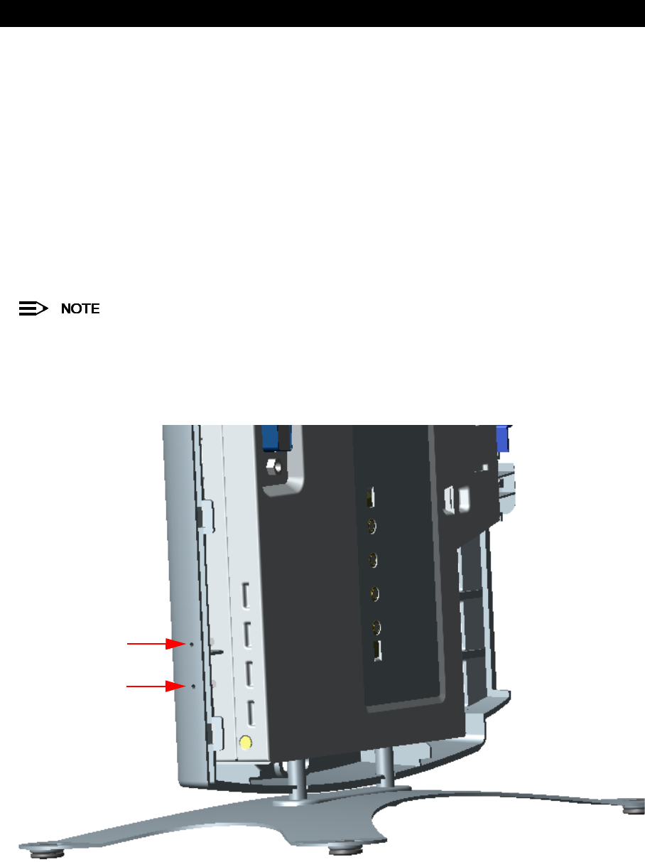
Troubleshooting
85
Recovery Procedures
The most common installation problems relate to IP addressing. For example, without the TFTP server IP Address,
you will not be able to download a new AP Image to the AP-600. IP Address management is fundamental. We suggest
you create a chart to document and validate the IP addresses for your system.
If the password is lost or forgotten, you will need to reset the AP-600 to default values. The Reset to Factory Default
Procedure resets configuration settings, but does not change the current AP Image.
If the AP-600 has a corrupted software image, follow the Forced Reload Procedure to erase the current AP Image and
download a new image.
Reset to Factory Default Procedure
Use this procedure to reset the network configuration values, including the Access Point’s IP address and subnet
mask. The current AP Image is not deleted. Follow this procedure if you forget the Access Point’s password:
1. Press and hold the RELOAD button for 10 seconds.
See RELOAD and RESET Buttons to identify the buttons. You need to use a pin or the end of a paperclip to
press a button.
Result: The AP-600 reboots, and the factory default network values are restored.
2. If not using DHCP, use the ScanTool or CLI over a serial connection to set the IP address, subnet mask, and other
IP parameters. See Command Line Interface (CLI) for CLI information.
Figure 7-1 RELOAD and RESET Buttons
RESET
RELOAD

Troubleshooting
86
Forced Reload Procedure
Use this procedure to erase the current AP Image and download a new AP Image. In some cases, specifically when a
missing or corrupted AP Image prevents successful booting, you may need to use ScanTool or the Bootloader CLI to
download a new executable AP Image.
This does not delete the AP-600’s configuration (in other words, the Forced Reload Procedure does not reset
to device to factory defaults). If you need to force the AP-600 to the factory default state after loading a new
AP image, use the Reset to Factory Default Procedure above.
For this procedure, you will first erase the AP Image currently installed on the unit and then use either ScanTool or the
Bootloader CLI (over the serial port) to set the IP address and download a new AP Image. Follow these steps:
1. While the unit is running, press the RESET button.
See RELOAD and RESET Buttons to identify the buttons. You need to use a pin or the end of a paperclip to
press a button.
Result: The AP-600 reboots and the indicators begin to flash.
!
By completing Step 2, the firmware in the AP-600 will be erased. You will need an Ethernet connection, a
TFTP server, and a serial cable (if using the Bootloader CLI) to reload firmware.
2. Press and hold the RELOAD button for about 20 seconds until the POWER LED turns amber.
Result: The AP-600 deletes the current AP Image.
3. Follow one of the procedures below to load a new AP Image to the Access Point:
–Download a New Image Using ScanTool
–Download a New Image Using the Bootloader CLI
Download a New Image Using ScanTool
To download the AP Image, you will need an Ethernet connection to the computer on which the TFTP server resides
and to a computer that is running ScanTool (this is either two separate computers connected to the same network or a
single computer running both programs).
ScanTool detects if an Access Point does not have a valid software image installed. In this case, the TFTP Server and
Image File Name parameters are enabled in the ScanTool’s
Change
screen so you can download a new image to the
unit. (These fields are grayed out if ScanTool does not detect a software image problem.)
Preparing to Download the AP Image
Before starting, you need to know the Access Point’s IP address, subnet mask, the TFTP Server IP Address, and the
AP Image file name. Make sure the TFTP server is running and configured to point to the folder containing the image
to be downloaded.
Download Procedure
Follow these steps to use ScanTool to download a software image to an Access Point with a missing image:
1. Download the latest software from http://www.proxim.com/support/.
2. Copy the latest software updates to your TFTP server.
3. Launch ScanTool.
4. Highlight the entry for the AP-600 you want to update and click Change.
5. Set IP Address Type to Static.
You need to assign static IP information temporarily to the Access Point since its DHCP client functionality is
not available when no image is installed on the device.
6. Enter an unused IP address that is valid on your network in the IP Address field. You may need to contact your
network administrator to get this address.
7. Enter the network’s Subnet Mask in the field provided.

Troubleshooting
87
8. Enter the network’s Gateway IP Address, if necessary. You may need to contact your network administrator to get
this address. You should only need to enter the default gateway address if the Access Point and the TFTP server
are separated by a router.
9. Enter the IP address of your TFTP server in the field provided.
10. Enter the Image File Name (including the file extension). Enter the full directory path and file name. If the file is
located in the default TFTP directory, you need enter only the file name.
11. Click OK.
–Result: The Access Point will reboot and the download will begin automatically. You should see downloading
activity begin after a few seconds within the TFTP server’s status screen.
12. Click OK when prompted that the device has been updated successfully to return to the
Scan List
screen.
13. Click Cancel to close the ScanTool.
14. When the download process is complete, configure the AP-600 as described in Installation & Basic Configuration
and Advanced Configuration.
Download a New Image Using the Bootloader CLI
To download the AP Image, you will need an Ethernet connection to the computer on which the TFTP server resides.
This can be any computer on the LAN or connected to the AP-600 with a cross-over Ethernet cable.
You must also connect the AP-600 to a computer with a standard serial cable and use a terminal client, such as
HyperTerminal. From the terminal, enter CLI Commands to set the IP address and download an AP Image.
Preparing to Download the AP Image
Before starting, you need to know the Access Point’s IP address, subnet mask, the TFTP Server IP Address, and the
AP Image file name. Make sure the TFTP server is running and configured to point to the folder containing the image
to be downloaded.
Download Procedure
1. Download the latest software from http://www.proxim.com/support/.
2. Copy the latest software updates to your TFTP server’s default directory.
3. Use a straight-through serial cable to connect the Access Point’s serial port to your computer’s serial port.
You must remove the Access Point’s cable cover and front cover to access the serial port.
4. Open your terminal emulation program (like HyperTerminal) and set the following connection properties:
•Com Port: <COM1, COM2, etc., depending on your computer>
•Baud rate: 9600
•Data Bits: 8
•Stop bits: 1
•Flow Control: None
•Parity: None
5. Under File -> Properties -> Settings -> ASCII Setup, enable the Send line ends with line feeds option.
Result: HyperTerminal sends a line return at the end of each line of code.
6. Press the RESET button on the AP-600.
Result: The terminal display shows Power On Self Tests (POST) activity. After approximately 30 seconds, a
message indicates: Sending Traps to SNMP manager periodically. After this message appears, press the
ENTER key repeatedly until the following prompt appears:
[Device name]>

Troubleshooting
88
7. Enter only the following statements:
[Device name]> set ipaddrtype static
[Device name]> set ipaddr <Access Point IP Address>
[Device name]> set ipsubmask <IP Mask>
[Device name]> set tftpipaddr <TFTP Server IP Address>
[Device name]> set tftpfilename <AP Image File Name, including file extension>
[Device name]> set ipgw <Gateway IP Address>
[Device name]> show ip (to confirm your new settings)
[Device name]> show tftp (to confirm your new settings)
[Device name]> reboot 0
Example:
[Device name]> set ipaddrtype static
[Device name]> set ipaddr 10.0.0.12
[Device name]> set ipsubmask 255.255.255.0
[Device name]> set tftpipaddr 10.0.0.20
[Device name]> set tftpfilename MyImage.bin
[Device name]> set ipgw 10.0.0.30
[Device name]> show ip
[Device name]> show tftp
[Device name]> reboot 0
Result: The AP-600 will reboot and then download the image file. You should see downloading activity begin after
a few seconds within the TFTP server’s status screen.
8. When the download process is complete, configure the AP-600 as described in Installation & Basic Configuration
and Advanced Configuration.
Setting IP Address using Serial Port and Normal CLI
Use the following procedure to set an IP address over the serial port using the CLI. The network administrator typically
provides the AP-600 IP address.
Hardware and Software Requirements
•Standard straight-through serial data (RS-232) cable with a one male DB-9 connector and one female DB-9
connector. The AP-600 comes with a female 9-pin serial port.
•ASCII Terminal software, such as HyperTerminal.
Attaching the Serial Port Cable
1. Unlock and remove the cable cover from the AP-600.
2. Remove the front cover from the AP-600 to reveal the serial port.
3. Connect one end of the serial cable to the AP-600 and the other end to a serial port on your computer.
4. Power on the computer and AP-600, if necessary.
Initializing the IP Address using CLI
After installing the serial port cable, you may use the CLI to communicate with the AP-600. CLI supports most generic
terminal emulation programs, such as HyperTerminal (which is included with the Windows operating systems). In
addition, many web sites offer shareware or commercial terminal programs you can download. Once the IP address
has been assigned, you can use the HTTP interface or the CLI over Telnet to complete configuration.
Follow these steps to assign the AP-600 an IP address:
1. Open your terminal emulation program (like HyperTerminal) and set the following connection properties:
•Com Port: <COM1, COM2, etc., depending on your computer>
•Baud rate: 9600
•Data Bits: 8
•Stop bits: 1
•Flow Control: None
•Parity: None
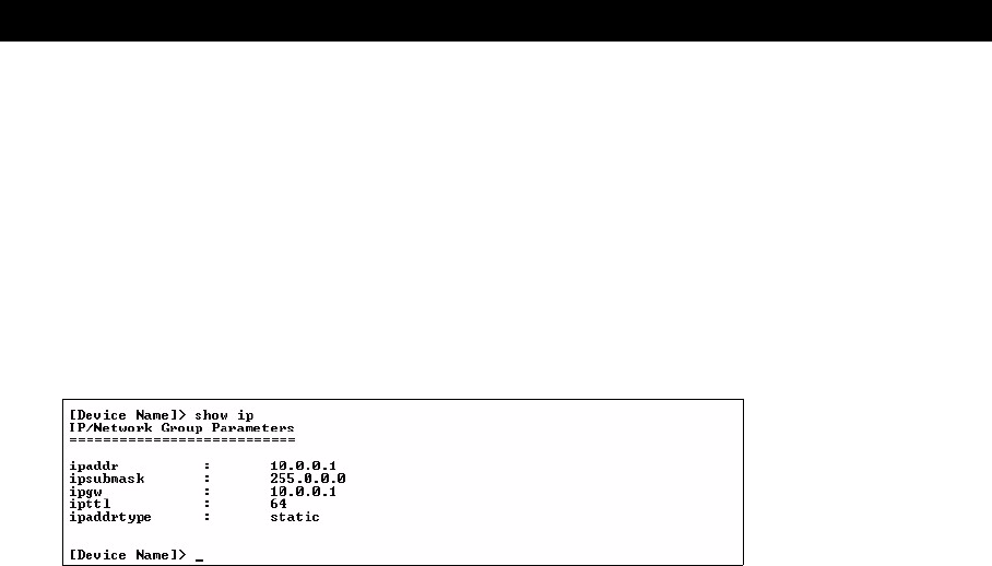
Troubleshooting
89
2. Under File -> Properties -> Settings -> ASCII Setup, enable the Send line ends with line feeds option.
Result: HyperTerminal sends a line return at the end of each line of code.
3. Press the RESET button on the AP-600 (see RELOAD and RESET Buttons to identify the location of the RESET
button).
Result: The terminal display shows Power On Self Tests (POST) activity, and then displays a CLI prompt, similar to
the example below. This process may take up to 90 seconds.
[Device name]> Please enter password:
4. Enter the CLI password (default is public).
Result: The terminal displays a welcome message and then the CLI Prompt:
[Device name]>
5. Enter show ip. Result: Network parameters appear:
Figure 7-2 Result of “show ip” CLI Command
6. Change the IP address and other network values using set and reboot CLI commands, similar to the example
below (use your own IP address and subnet mask). Note that IP Address Type is set to Dynamic by default. If you
have a DHCP server on your network, you should not need to manually configure the Access Point’s IP address;
the Access Point will obtain an IP address from the network’s DHCP server during boot-up.
Result: After each entry the CLI reminds you to reboot; however wait to reboot until all commands have been
entered.
[Device name]> set ipaddrtype static
[Device name]> set ipaddr <IP Address>
[Device name]> set ipsubmask <IP Subnet Mask>
[Device name]> set ipgw <Default Gateway IP Address>
[Device name]> show ip (to confirm your new settings)
[Device name]> reboot 0
7. After the AP-600 reboots, verify the new IP address by reconnecting to the CLI and enter a show ip command.
Alternatively, you can ping the AP-600 from a network computer to confirm that the new IP address has taken
effect.
8. When the proper IP address is set, use the HTTP interface or CLI over Telnet to configure the rest of the unit’s
operating parameters.

Troubleshooting
90
System Alarms (Traps)
Security Alarms
Wireless Interface Card Alarms
Operational Alarms
FLASH Memory Alarms
TFTP Alarms
Image Alarms
Standard MIB-II (RFC 1213) Alarms
Bridge MIB (RFC 1493) Alarms
oriTrapAuthenticationFailure A client has failed to authenticate using one of the following
authentication methods: MAC Access Control Table, RADIUS
MAC Authentication, or 802.1x Authentication (for 802.1x, EAP
type is specified)
oriTrapUnauthorizedManagerDetected An unauthorized manager has attempted to view and/or modify
parameters
oriTrapWLCNotPresent Wireless radio not present
oriTrapWLCFailure Wireless radio general failure
riTrapWLCRemoval Wireless radio removal
oriTrapWLCIncompatibleFirmware Wireless radio incompatible firmware detected
oriTrapWLCVoltageDiscrepancy Wireless radio voltage discrepancy detected
oriTrapWLCIncompatibleVendor Wireless radio incompatible vendor detected
oriTrapWLCFirmwareDownloadFailure Wireless radio firmware download failure detected
oriTrapWatchDogTimerExpired Watch Dog Timer has expired
oriTrapRADIUSServerNotResponding RADIUS Server is not responding or error communicating with RADIUS Server
oriTrapModuleNotInitialized Module has not been initialized
oriTrapDeviceRebooting Device is rebooting
oriTrapTaskSuspended Task suspension has been detected
oriTrapBootPFailed BootP failure detected (no response from BootP Server)
oriTrapDHCPFailed DHCP Client failure detected (no response from DHCP server)
oriTrapFlashMemoryEmpty Flash memory empty
oriTrapFlashMemoryCorrupted Flash memory data corrupted
oriTrapTFTPFailedOperation TFTP (upload or download) failure detected
oriTrapTFTPOperationInitiated TFTP (upload or download) operation initiated
oriTrapTFTPOperationCompleted TFTP (upload or download) operation completed
oriTrapZeroSizeImage Zero size image has been downloaded to device
oriTrapInvalidImage Invalid image has been downloaded to device
oriTrapImageTooLarge Image downloaded to device is too big
oriTrapIncompatibleImage Incompatible image has been downloaded to device
coldStart Device has been turned on or rebooted
linkUp Device Link is up (Ethernet interface is up)
linkDown Device Link is down (Ethernet interface is down)
newRoot New root has been added to Bridge
topologyChange Network Topology change has been detected

Troubleshooting
91
Related Applications
RADIUS Authentication Server
If you enabled RADIUS Authentication on the AP-600, make sure that your network’s RADIUS servers are operational.
Otherwise, clients will not be able to log in. There are several reasons the authentication server services might be
unavailable, here are two typical things to check:
•Make sure you have the proper RADIUS authentication server information setup configured in the AP-600. Check
the RADIUS Authentication Server’s Shared Secret and Destination Port number (default is 1812; for RADIUS
Accounting, the default is 1813).
•Make sure the RADIUS authentication server RAS setup matches the AP-600.
TFTP Server
The “Trivial File Transfer Protocol” (TFTP) server allows you to transfer files across a network. You can upload
configuration files from the AP-600 for backup or copying, and you can download configuration files or new software
images. The TFTP software is located on the ORiNOCO AP-600 Installation CD-ROM.
If a TFTP server is not configured and running, you will not be able to download and upload images and configuration
files to/from the AP-600. Remember that the TFTP server does not have to be local, so long as you have a valid TFTP
IP address. Note that you do not need a TFTP server running unless you want to transfer files to or from the AP-600.
After the TFTP server is installed:
•Check to see that TFTP is configured to point to the directory containing the AP Image.
•Make sure you have the proper TFTP server IP Address, the proper AP Image file name, and that the TFTP server
is connected.
•

Troubleshooting
92

92
A
Command Line Interface (CLI)
In This Appendix
This section describes the AP-600’s Command Line (CLI) Interface. CLI commands can be used to initialize,
configure, and manage the Access Point.
–CLI commands may be entered in real time through a keyboard or submitted with CLI scripts.
–The CLI is available through both the Serial Port interface and over the Ethernet interface using Telnet.
All CLI commands and parameters are case-sensitive.
•General Notes
•Command Line Interface (CLI) Variations
•CLI Command Types
•Using Tables & User Strings
•Configuring the AP-600 using CLI commands
•Set Basic Configuration Parameters using CLI Commands
•Other Network Settings
•CLI Monitoring Parameters
•Parameter Tables
General Notes
Prerequisite Skills and Knowledge
To use this document effectively, you should have a working knowledge of Local Area Networking (LAN) concepts,
network access infrastructures, and client-server relationships. In addition, you should be familiar with software setup
procedures for typical network operating systems and servers.
Notation Conventions
•Computer prompts are shown as constant width type. For example: [Device name]>
•Information that you input as shown is displayed in bold constant width type. For example:
[Device name]> set ipaddr 10.0.0.12
•The names of keyboard keys, software buttons, and field names are displayed in bold type. For example: Click the
Configure button.
•Screen names are displayed in bold italics. For example, the
System Status
screen.
Important Terminology
•Configuration Files - Database files containing the current Access Point configuration. Configuration items include
the IP Address and other network-specific values. Config files may be downloaded to the Access Point or uploaded
for backup or troubleshooting.
•Download vs. Upload - Downloads transfer files to the Access Point. Uploads transfer files from the Access Point.
The TFTP server performs file transfers in both directions.

Command Line Interface (CLI)
93
•Group - A logical collection of network parameter information. For example, the System Group is composed of
several related parameters. Groups can also contain Tables. All items for a given Group can be displayed with a
show <Group> CLI Command.
•Image File - The Access Point software executed from RAM. To update an Access Point you typically download a
new Image File. This file is often referred to as the “AP Image”.
•Parameter - A fundamental network value that can be displayed and may be changeable. For example, the Access
Point must have a unique IP Address and the Wireless interface must be assigned an SSID. Change parameters
with the CLI set Command, and view them with the CLI show Command.
•Table - Tables hold parameters for several related items. For example, you can add several potential managers to
the SNMP Table. All items for a given Table can be displayed with a show <Table> CLI Command.
•TFTP - Refers to the TFTP Server, used for file transfers.
Navigation and Special Keys
This CLI supports the following navigation and special key functions to move the cursor along the prompt line.
CLI Error Messages
The following table describes the error messages associated with improper inputs or expected CLI behavior.
Command Line Interface (CLI) Variations
Administrators use the CLI to control Access Point operation and monitor network statistics. The AP-600 supports two
types of CLI: the Bootloader CLI and the normal CLI. The Bootloader CLI provides a limited command set, and is used
when the current AP Image is bad or missing. The Bootloader CLI allows you to assign an IP Address and download a
new image. Once the image is downloaded and running, the Access Point uses the normal CLI. This guide covers the
normal CLI unless otherwise specified.
Key Combination Operation
Delete or Backspace Delete previous character
Ctrl-A Move cursor to beginning of line
Ctrl-E Move cursor to end of line
Ctrl-F Move cursor forward one character
Ctrl-B Move cursor back one character
Ctrl-D Delete the character the cursor is on
Ctrl-U Delete all text to left of cursor
Ctrl-P Go to the previous line in the history buffer
Ctrl-N Go to the next line in the history buffer
Tab Complete the command line
? List available commands
Error Message Description
Syntax error Invalid syntax entered at the command prompt.
Invalid command A non-existent command has been entered at the command prompt.
Invalid parameter name An invalid parameter name has been entered at the command prompt.
Invalid parameter value An invalid parameter value has been entered at the command prompt.
Invalid table index An invalid table index has been entered at the command prompt.
Invalid table parameter An invalid table parameter has been entered at the command prompt.
Invalid table parameter value An invalid table parameter value has been entered at the command prompt.
Read only parameter User is attempting to configure a read-only parameter.
Incorrect password An incorrect password has been entered in the CLI login prompt.
Download unsuccessful The download operation has failed due to incorrect TFTP server IP Address or file name.
Upload unsuccessful The upload operation has failed due to incorrect TFTP server IP Address or file name.
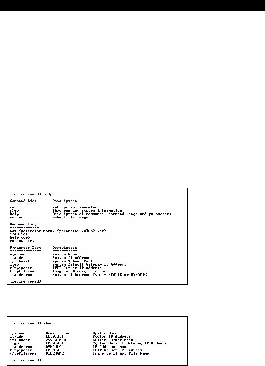
Command Line Interface (CLI)
94
Bootloader CLI
The Bootloader CLI is a minimal subset of the normal CLI used to perform initial configuration of the AP-600. This
interface is only accessible via the serial interface if the AP-600 does not contain a software image or a download
image command over TFTP has failed.
The Bootloader CLI provides you with the ability to configure the initial setup parameters as well as download a
software image to the device.
The following functions are supported by the Bootloader CLI:
–configuration of initial device parameters using the set command
–show command to view the device’s configuration parameters
–help command to provide additional information on all commands supported by the Bootloader CLI
–reboot command to reboot the device
The parameters supported by the Bootloader CLI (for viewing and modifying) are:
–System Name
–IP Address Assignment Type
–IP Address
–IP Mask
–Gateway IP Address
–TFTP Server IP Address
–Image File Name (including the file extension)
The following lists display the results of using the help command in the Bootloader CLI:
Figure A-1 Results of “help” bootloader CLI command
The following lists display the results of using the show command in the Bootloader CLI:
Figure A-2 Results of “show” bootloader CLI command

Command Line Interface (CLI)
95
CLI Command Types
This guide divides CLI Commands into two categories: Operational and Parameter Controls.
Operational CLI Commands
These commands affect Access Point behavior, such as downloading, rebooting, and so on. After entering commands
(and parameters, if any) press the Enter key to execute the Command Line.
Operational commands include:
•?: Typing a question mark lists CLI Commands or parameters, depending on usage (you do not need to type Enter
after typing this command)
•done, exit, quit: Terminates the CLI session
•download: Uses TFTP server to download “image”, “config”, or “bootloader upgrade” files to Access Point
•help: Displays general CLI help information or command help information, such as command usage and syntax
•history: Remembers commands to help avoid re-entering complex statements
•passwd: Sets the Access Point’s CLI password
•reboot: Reboots the Access Point in the specified time
•search: Lists the parameters in a specified Table
•upload: Uses TFTP server to upload “config” files from Access Point to TFTP default directory or specified path
? (List Commands)
This command can be used in a number of ways to display available commands and parameters.
The following table lists each operation and provides a basic example. Following the table are detailed examples and
display results for each operation.
Example 1. Display Command list
To display the Command List, enter ?.
[Device Name]>?
Figure A-3 Result of “?” CLI command
Example 2. Display specific Commands
To show all commands that start with specified letters, enter one or more letters, then ? with no space between letters
and ?.
[Device Name]>s?
Figure A-4 Result of “s?” CLI command
Operation Basic Example
Display the Command List (Example 1) [Device Name]>?
Display commands that start with specified letters (Example 2) [Device Name]>s?
Display parameters for set and show Commands (Examples 3a and 3b) [Device Name]>set ?
[Device Name]>show ipa?
Prompt to enter successive parameters for Commands (Example 4) [Device Name]>download ?
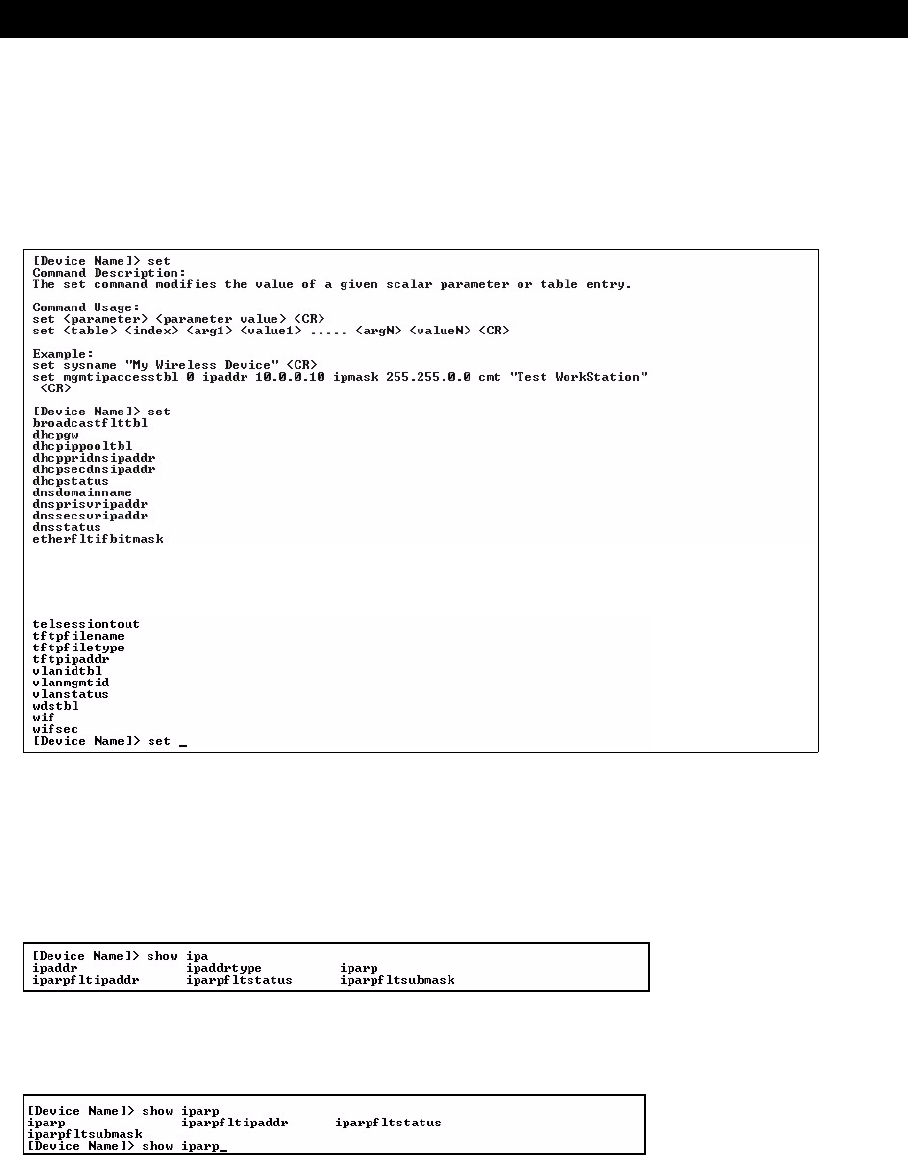
Command Line Interface (CLI)
96
Example 3. Display parameters for set and show
Example 3a allows you to see every possible parameter for the set (or show) commands. Notice from example 3a that
the list is very long. Example 3b shows how to display a subset of the parameters based on initial parameter letters.
Example 3a. Display every parameter that can be changed
[Device Name]>set ?
Figure A-5 Result of “set ?” CLI command
Example 3b. Display parameters based on letter sequence
This example shows entries for parameters that start with the letter “i”. The more letters you enter, the fewer the results
returned. Notice that there is no space between the letters and the question mark.
[Device Name]> show ipa?
Figure A-6 Result of “show ipa?” CLI command
[Device Name]> show iparp?
Figure A-7 Result of “show iparp?” CLI command
.
.
.
.

Command Line Interface (CLI)
97
Example 4. Display Prompts for Successive Parameters
Enter the command, a space, and then ?. Then, when the parameter prompt appears, enter the parameter value.
Result: The parameter is changed and a new CLI line is echoed with the new value (in the first part of the following
example, the value is the IP Address of the TFTP server).
After entering one parameter, you may add another ? to the new CLI line to see the next parameter prompt, and so on
until you have entered all of the required parameters. The following example shows how this is used for the download
Command. The last part of the example shows the completed download Command ready for execution.
[Device Name]> download ?
<TFTP IP Address>
[Device Name]> download 169.254.128.133 ?
<File Name>
[Device Name]> download 169.254.128.133 apimage ?
<file type (config/img/bootloader)>
[Device Name]> download 169.254.128.133 apimage img <CR>
done, exit, quit
Each of the following commands ends a CLI session:
[Device Name]> done
[Device Name]> exit
[Device Name]> quit
download
Downloads the specified file from a TFTP server to the Access Point. Executing download in combination with the
asterisks character (“*”) will make use of the previously set TFTP parameters. Executing download without parameters
will display command help and usage information.
1. Syntax to download a file:
Device Name]>download <tftp server address> <path and filename> <file type>
Example:
[Device Name]>download 192.168.1.100 APImage2 img
2. Syntax to display help and usage information:
[Device Name]>download
3. Syntax to execute the download Command using previously set (stored) TFTP Parameters:
[Device Name]>download *
help
Displays instructions on using control-key sequences for navigating a Command Line and displays command
information and examples.
1. Using help as the only argument:
[Device Name]>help
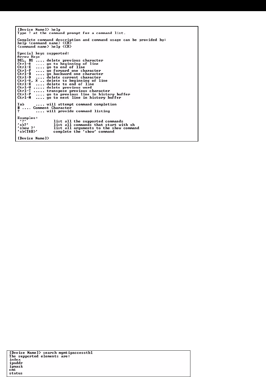
Command Line Interface (CLI)
98
Figure A-8 Results of “help” CLI command
2. Complete command description and command usage can be provided by:
[Device Name]>help <command name>
[Device Name]><command name> help
history
Shows content of Command History Buffer. The Command History Buffer stores command statements entered in the
current session. To avoid re-entering long command statements, use the keyboard “up arrow” (Ctrl-P) and “down
arrow” (Ctrl-N) keys to recall previous statements from the Command History Buffer. When the desired statement
reappears, press the Enter key to execute, or you may edit the statement before executing it.
[Device Name]> history
passwd
Changes the CLI Password.
[Device Name]> passwd oldpassword newpassword newpassword
reboot
Reboots Access Point after specified number of seconds. Specify a value of 0 (zero) for immediate reboot.
[Device Name]> reboot 0
[Device Name]> reboot 30
search
Lists the parameters supported by the specified table. This list corresponds to the table information displayed in the
HTTP interface. In this example, the CLI returns the list of parameters that make up an entry in the IP Access Table.
[Device Name]> search mgmtipaccesstbl
Figure A-9 Results of “search mgmtipaccesstbl” CLI command

Command Line Interface (CLI)
99
upload
Uploads a text-based configuration file from the AP-600 to the TFTP Server. Executing upload with the asterisk
character (“*”) will make use of the previously set/stored TFTP parameters. Executing upload without parameters will
display command help and usage information.
1. Syntax to upload a file:
[Device Name]>upload <tftp server address> <path and filename> <filetype>
Example:
[Device Name]>upload 192.168.1.100 APconfig.sys config
2. Syntax to display help and usage information:
[Device Name]>help upload
3. Syntax to execute the upload command using previously set (stored) TFTP Parameters:
[Device Name]>upload *
Parameter Control Commands
The following sections cover the two Parameter Control Commands (show and set) and include several tables
showing parameter properties. These commands allow you to view (show) all parameters and statistics and to change
(set) parameters.
•show: To see any Parameter or Statistic value, you can specify a single parameter, a Group, or a Table.
•set: Use this CLI Command to change parameter values. You can use a single CLI statement to modify Tables, or
you can modify each parameter separately.
“show” CLI Command
Displays the value of the specified parameter, or displays all parameter values of a specified group (parameter table).
Groups contain Parameters and Tables. Tables contain parameters for a series of similar entities.
To see a definition and syntax example, type only show and then press the Enter key. To see a list of available
parameters, enter a question mark (?) after show (example: show ?).
Syntax:
[Device Name]>show <parameter>
[Device Name]>show <group>
[Device Name]>show <table>
Examples:
[Device Name]>show ipaddr
[Device Name]>show network
[Device Name]>show mgmtipaccesstbl
“set” CLI Command
Sets (modifies) the value of the specified parameter. To see a definition and syntax example, type only set and then
press the Enter key. To see a list of available parameters, enter a space, then a question mark (?) after set (example:
set?).
Syntax:
[Device Name]>set <parameter> <value>
[Device Name]>set <table> <index> <argument 1> <value 1> ... <argument N> <value N>
Example:
[Device Name]>set sysloc “Main Lobby”
[Device Name]>set mgmtipaccesstbl 0 ipaddr 10.0.0.10 submask 255.255.0.0
Configuring Objects that Require Reboot
Certain objects supported by the Access Point require a device reboot in order for the changes to take effect. In order
to inform the end-user of this behavior, the CLI provides informational messages when the user has configured an
object that requires a reboot. The following messages are displayed as a result of the configuring such object or
objects.

Command Line Interface (CLI)
100
Example 1: Configuring objects that require the device to be rebooted
The following message is displayed every time the user has configured an object that requires the device to be
rebooted.
[Device Name]>set ipaddr 135.114.73.10
The following elements require reboot
ipaddr
Example 2: Executing the “exit”, “quit”, or “done” commands when an object that requires reboot has
been configured
In addition to the above informational message, the CLI also provides a message as a result of the exit, quit, or done
command if changes have been made to objects that require reboot. If you make changes to objects that require
reboot and execute the exit command the following message is displayed:
[Device Name]>exit<CR> OR quit<CR> OR done<CR>
Modifications have been made to parameters that require the device to be rebooted.
These changes will only take effect after the next reboot.
“set” and “show” Command Examples
In general, you will use the CLI show Command to view current parameter values and use the CLI set Command to
change parameter values. As shown in the following examples, parameters may be set individually or all parameters
for a given table can be set with a single statement.
Example 1 - Set the Access Point IP Address Parameter
Syntax:
[Device Name]>set <parameter name> <parameter value>
Example:
[Device Name]> set ipaddr 10.0.0.12
Result: IP Address will be changed when you reboot the Access Point. The CLI reminds you when rebooting is
required for a change to take effect. To reboot immediately, enter reboot 0 (zero) at the CLI prompt.
Example 2 - Create a table entry or row
Use 0 (zero) as the index to a table when creating an entry. When creating a table row, only the mandatory table
elements are required (comment is usually an optional table element). For optional table elements, the default value is
generally applied if you do not specify a value.
Syntax:
[Device Name]>set <table name> <table index> <element 1> <value 1> …
<element n> <value n>
Example:
[Device Name]> set mgmtipaccesstbl 0 ipaddr 10.0.0.10 ipmask 255.255.0.0
Result: A new table entry is created for IP address 10.0.0.10 with a 255.255.0.0 subnet mask.
Example 3 - Modify a table entry or row
Use the index to be modified and the table elements you would like to modify. For example, suppose the IP Access
Table has one entry and you wanted to modify the IP address:
[Device Name]>set mgmtipaccesstbl 1 ipaddr 10.0.0.11
You can also modify several elements in the table entry. Enter the index number and specific table elements you would
like to modify. (Hint: Use the search Command to see the elements that belong to the table.)
[Device Name]>set mgmtipaccesstbl 1 ipaddr 10.0.0.12 ipmask 255.255.255.248
cmt “First Row”
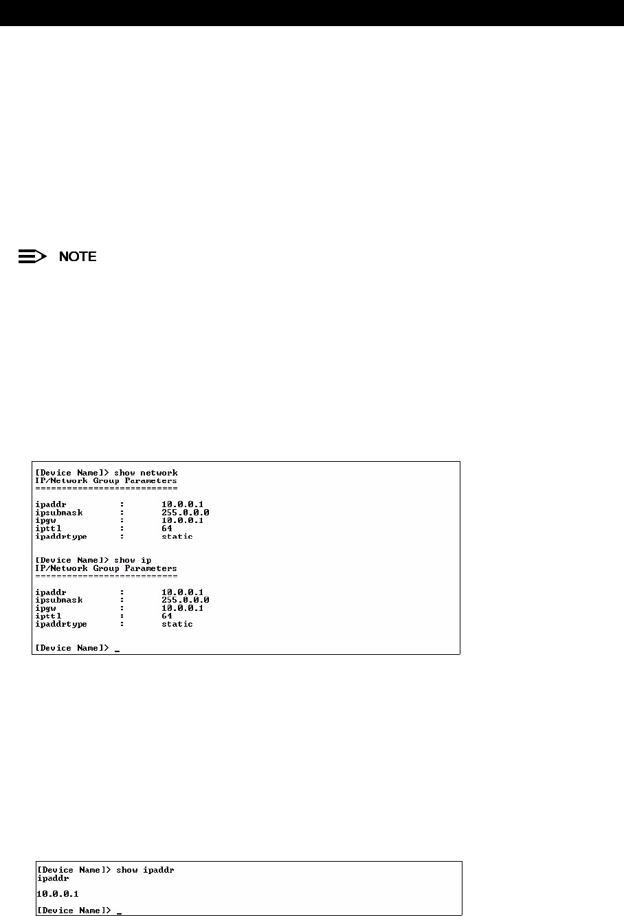
Command Line Interface (CLI)
101
Example 4 - Enable, Disable, or Delete a table entry or row
The following example illustrates how to manage the second entry in a table.
Syntax:
[Device Name]>set <Table> index status <enable, disable, delete>
[Device Name]>set <Table> index status <1=enable, 2=disable, 3=delete>
Example:
[Device Name]>set mgmtipaccesstbl 2 status enable
[Device Name]>set mgmtipaccesstbl 2 status disable
[Device Name]>set mgmtipaccesstbl 2 status delete
[Device Name]>set mgmtipaccesstbl 2 status 2
You may need to enable a disabled table entry before you can change the entry’s elements.
Example 5 - Show the Group Parameters
This example illustrates how to view all elements of a group or table.
Syntax:
[Device Name]> show <group name>
Example:
[Device Name]>show network
Result: The CLI displays network group parameters. Note show network and show ip return the same data.
Figure A-10 Results of “show network” and “show ip” CLI Commands
Example 6 - Show Individual and Table Parameters
1. View a single parameter.
Syntax:
[Device Name]>show <parameter name>
Example:
[Device Name]> show ipaddr
Result: Displays the Access Point IP address.
Figure A-11 Result of “show ipaddr” CLI Command

Command Line Interface (CLI)
102
2. View all parameters in a table.
Syntax:
[Device Name]> show <table name>
Example:[Device Name]> show mgmtipaccesstbl
Result: Displays the IP Access Table and its entries.
Using Tables & User Strings
Working with Tables
Each table element (or parameter) must be specified, as in the example below.
[Device Name]>set mgmtipaccesstbl 0 ipaddr 10.0.0.10 ipmask 255.255.0.0
Below are the rules for creating, modifying, enabling/disabling, and deleting table entries.
•Creation
–The table name is required.
–The table index is required – for table entry/instance creation the index is always zero (0).
–The order in which the table arguments or objects are entered in not important.
–Parameters that are not required can be omitted, in which case they will be assigned the default value.
•Modification
–The table name is required.
–The table index is required – to modify the table, “index” must be the index of the entry to be modified.
–Only the table objects that are to be modified need to be specified. Not all the table objects are required.
–If multiple table objects are to be modified the order in which they are entered is not important.
–If the entire table entry is to be modified, all the table objects have to be specified.
•Enabling/Disabling
–The table name is required.
–The table index is required – for table enabling/disabling the index should be the index of the entry to be
enabled/disabled.
–The entry’s new state (either “enable” or “disable”) is required.
•Deletion
–The table name is required.
–The table index is required – for table deletion the index should be the index of the entry to be deleted.
–The word “delete” is required.
Using Strings
Since there are several string objects supported by the AP-600, a string delimiter is required for the strings to be
interpreted correctly by the command line parser. For this CLI implementation, the single quote or double quote
character can be used at the beginning and at the end of the string.
For example:
[Device Name]> set sysname Lobby - Does not need quote marks
[Device Name]> set sysname “Front Lobby” - Requires quote marks.
The scenarios supported by this CLI are:
The string delimiter does not have to be used for every string object. The single quote or double quote only has to be
used for string objects that contain blank space characters. If the string object being used does not contain blank
spaces, then the string delimiters, single or double quotes, mentioned in this section are not required.
“My Desk in Nieuwegein”Double Quotes
‘My Desk in Nieuwegein’Single Quotes
“My ‘Desk’ in Nieuwegein”Single Quotes within Double Quotes
‘My “Desk” in Nieuwegein’Double Quotes within Single Quotes
“Daniel’s Desk in Nieuwegein”One Single Quote within Double Quotes
‘Daniel”s Desk in Nieuwegein’One Double Quote within Single Quotes

Command Line Interface (CLI)
103
Configuring the AP-600 using CLI commands
Log into the AP-600 using HyperTerminal
1. Open your terminal emulation program (like HyperTerminal) and set the following connection properties:
•Com Port: <COM1, COM2, etc., depending on your computer>
•Baud rate: 9600
•Data Bits: 8
•Stop bits: 1
•Flow Control: None
•Parity: None
2. Under File -> Properties -> Settings -> ASCII Setup, enable the Send line ends with line feeds option.
Result: HyperTerminal sends a line return at the end of each line of code.
3. Enter the CLI password (default is public).
Proxim recommends changing your default passwords immediately. To perform this operation using CLI
commands, refer to Change Passwords.
Log into the AP-600 using Telnet
The CLI commands can be used to access, configure, and manage the AP-600 using Telnet. Follow these steps:
1. Confirm that your computer’s IP address is in the same IP subnet as the AP-600.
If you have not previously configured the Access Point’s IP address and do not have a DHCP server on the
network, the Access Point will default to an IP address of 169.254.128.132.
2. Go to the DOS command prompt on your computer.
3. Type telnet <IP Address of the unit>.
4. Enter the CLI password (default is public).
Proxim recommends changing your default passwords immediately. To perform this operation using CLI
commands, refer to Change Passwords.
Set Basic Configuration Parameters using CLI Commands
There are a few basic configuration parameters that you may want to setup right away when you receive the AP-600.
For example:
–Set System Name, Location and Contact Information
–Set Static IP Address for the AP-600
–Download an AP-600 Configuration File from your TFTP Server
–Set Network Names for the Wireless Interface
–Set WEP Encryption for the Wireless Interface
–Download an AP-600 Configuration File from your TFTP Server
–Backup your AP-600 Configuration File
Set System Name, Location and Contact Information
[Device Name]>set sysname <system name> sysloc <Unit Location>
[Device Name]>set sysctname <Contact Name (person responsible for system)>
[Device Name]>set sysctphone <Contact Phone Number> sysctemail <Contact E-mail address>
[Device Name]>show system
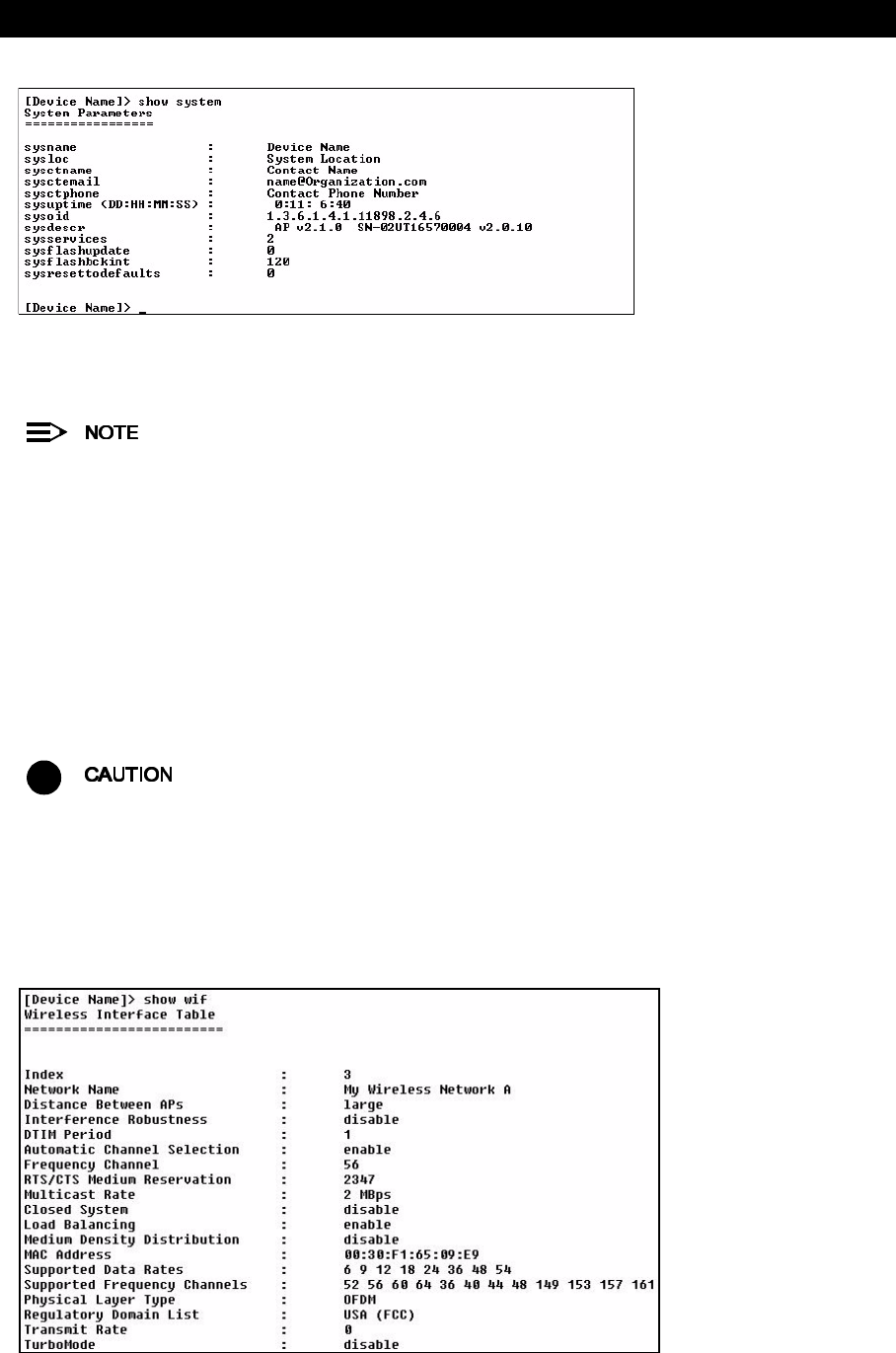
Command Line Interface (CLI)
104
Figure A-12 Result of “show system” CLI Command
Set Static IP Address for the AP-600
The IP Subnet Mask of the AP-600 must match your network’s Subnet Mask.
[Device Name]>set ipaddrtype static
[Device Name]>set ipaddr <fixed IP address of unit>
[Device Name]>set ipsubmask <IP Mask (default = 255.0.0.0)>
[Device Name]>set ipgw <gateway IP address (default = 169.254.128.133)>
[Device Name]>show network
Change Passwords
[Device Name]>passwd <Old Password> <New Password> <Confirm Password> (CLI password)
[Device Name]>set httppasswd <New Password> (HTTP interface password)
[Device Name]>set snmprpasswd <New Password> (SNMP read password)
[Device Name]>set snmprwpasswd <New Password> (SNMP read/write)
[Device Name]>reboot 0
!
Proxim strongly urges you to change the default passwords to restrict access to your network devices to
authorized personnel. If you lose or forget your password settings, you can always perform the Reset to
Factory Default Procedure.
Set Network Names for the Wireless Interface
[Device Name]>set wif 3 netname <Network Name (SSID) for wireless interface>
[Device Name]>show wif
Figure A-13 Results of “show wif” CLI command for an AP-600a
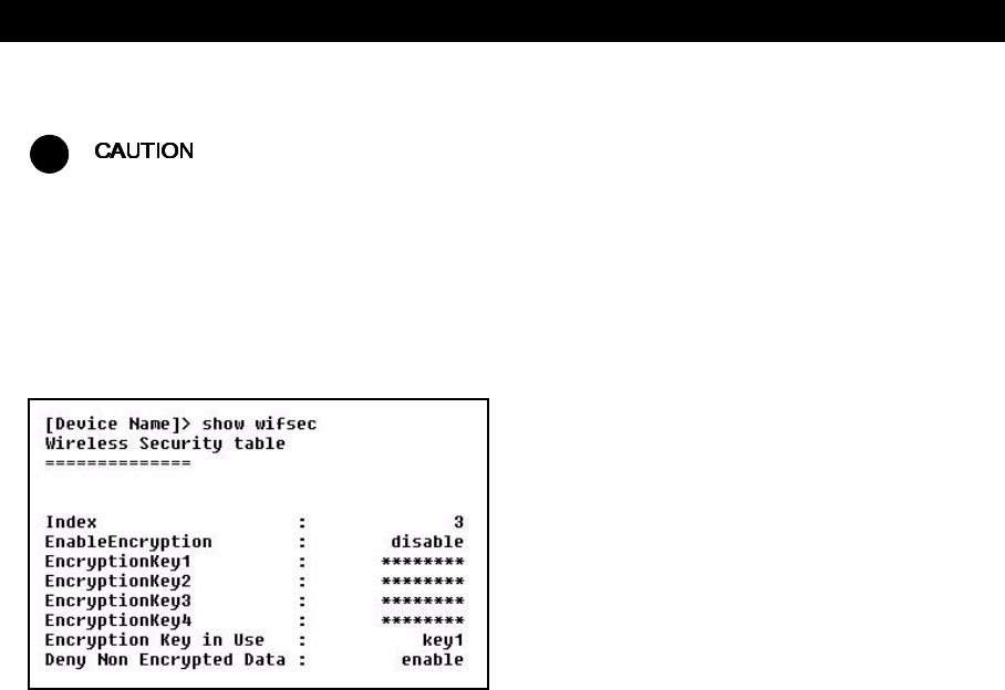
Command Line Interface (CLI)
105
Set WEP Encryption for the Wireless Interface
!
Wireless clients must be configured with the same encryption key to be able to communicate with the AP-600.
The AP-600 can only support one Key Length (so each of the configured keys must have the same length).
The available key sizes vary based on the Access Point’s model. See Security Encryption Key Length Table
for more information.
You can set up to four encryption keys. This example describes setting encryption Key 1 on the wireless card in Slot A.
[Device Name]>set wifsec 3 encryptstatus enable encryptkey1 <WEP key (number of characters
vary depending on AP model)> encryptkeytx 1
[Device Name]>show wifsec
Figure A-14 Result of “show wifsec” CLI Command
Download an AP-600 Configuration File from your TFTP Server
Begin by starting your TFTP program. It must be running and configured to transmit and receive.
[Device Name]>set tftpfilename <file name> tftpfiletype config
tftpipaddr <IP address of your TFTP server>
[Device Name]>show tftp (to ensure the filename, file type, and the IP address are correct)
[Device Name]>download *
[Device Name]>reboot 0
After following the complete process (above) once, you can download a file of the same name (so long as all the other
parameters are the same), with the following command:
[Device Name]>download *
Backup your AP-600 Configuration File
Begin by starting your TFTP program. It must be running and configured to transmit and receive.
[Device Name]>upload <TFTP Server IP address> <tftpfilename (such as “config.sys”)> config
[Device Name]>show tftp (to ensure the filename, file type, and the IP address are correct)
After setting the TFTP parameters, you can backup your current file (so long as all the other parameters are the same),
with the following command:
[Device Name]>upload *

Command Line Interface (CLI)
106
Other Network Settings
There are other configuration settings that you may want to set for the AP-600. Some of them are listed below.
–Configure the AP-600 as a DHCP Server
–Configure the DNS Client
–Maintain Client Connections using Link Integrity
–Change your Wireless Interface Settings
–Set Ethernet Speed and Transmission Mode
–Set Interface Management Services
–Configure MAC Access Control
–Set RADIUS Parameters
Refer to Advanced Configuration for more information on these settings.
Configure the AP-600 as a DHCP Server
You must have at least one entry in the DHCP Server IP Address Pool Table before you can set the DHCP
Server Status to Enable.
[Device Name]>set dhcpstatus disable
[Device Name]>set dhcpippooltbl 0 startipaddr <start ip address>
endipaddr <end ip address>
[Device Name]>set dhcpgw <gateway ip address>
[Device Name]>set dhcppridnsipaddr <primary dns ip address>
[Device Name]>set dhcpsecdnsipaddr <secondary dns ip address>
[Device Name]>set dhcpstatus enable
[Device Name]>reboot 0
!
Before enabling this feature, confirm that the IP address pools you have configured are valid addresses on the
network and do not overlap the addresses assigned by any other DHCP server on the network. Enabling this
feature with incorrect address pools will cause problems on your network.
Configure the DNS Client
[Device Name]>set dnsstatus enable
[Device Name]>set dnsprisvripaddr <IP address of primary DNS server>
[Device Name]>set dnssecsvripaddr <IP address of secondary DNS server>
[Device Name]>set dnsdomainname <default domain name>
[Device Name]>show dns
Figure A-15 Results of “show dns” CLI command

Command Line Interface (CLI)
107
Maintain Client Connections using Link Integrity
[Device Name]>show linkinttbl (this shows the current links)
[Device Name]>set linkinttbl <1-5 (depending on what table row you wish to address)>
ipaddr <ip address of the host computer you want to check>
[Device Name]>set linkintpollint <the interval between link integrity checks>
[Device Name]>set linkintpollretx <number of times to retransmit before considering
the link down>
[Device Name]>set linkintstatus enable
[Device Name]>show linkinttbl (confirm new settings)
[Device Name]>reboot 0
Change your Wireless Interface Settings
See Wireless (AP-600a) or Wireless (AP-600b) for information on the parameters listed below.
Autochannel Select (ACS)
ACS is enabled by default. Reboot after disabling or enabling ACS.
[Device Name]>set wif 3 autochannel <enable/disable>
[Device Name]>reboot 0
Enable 2X Turbo Mode (AP-600a Only)
[Device Name]>set wif 3 turbo <enable/disable>
[Device Name]>reboot 0
Enable/Disable Interference Robustness (AP-600b Only)
[Device Name]>set wif 3 interrobust <enable/disable>
Enable/Disable Closed System (AP-600b Only)
[Device Name]>set wif 3 closedsys <enable/disable>
When disabled, a client configured with the Network Name “ANY” can connect to the AP-600b. This feature is
not currently available for the AP-600a.
Enable/Disable Load Balancing (AP-600b Only)
[Device Name]>set wif 3 ldbalance <enable/disable>
Enable/Disable Medium Density Distribution (AP-600b Only)
[Device Name]>set wif 3 meddendistrib <enable/disable>
Command Line Interface (CLI)
108
Set the Distance Between APs (AP-600b Only)
[Device Name]>set wif 3 distaps <large, medium, small, minicell, microcell>
[Device Name]>reboot 0
The distance between APs should not be approximated. It is calculated by means of a manual Site Survey, in
which an AP-600 is set up and clients are tested throughout the area to determine signal strength and
coverage, and local limits such as physical interference are investigated. From these measurements the
appropriate cell size and density is determined, and the optimum distance between APs is calculated to suit
your particular business requirements.
Set the Multicast Rate (AP-600b Only)
[Device Name]>set wif 3 multrate <1,2,5.5,11 (Mbits/sec)>
The Distance Between APs must be set before the Multicast Rate.
Set Ethernet Speed and Transmission Mode
[Device Name]>set etherspeed <value (see below)>
[Device Name]>reboot 0
Set Interface Management Services
Edit Management IP Access Table
[Device Name]>set mgmtipaccesstbl <index> ipaddr <IP address> ipmask <subnet mask>
Configure Management Ports
[Device Name]>set snmpifbitmask <0 - 7 (default is 7 see below)>
[Device Name]>set httpifbitmask <0 - 7 (default is 7 see below)>
[Device Name]>set telifbitmask <0 - 7 (default is 7 see below)>
Choose from the following values:
Set Communication Ports
[Device Name]>set httpport <HTTP port number (default is 80)>
[Device Name]>set telport <Telnet port number (default is 23)>
Ethernet Speed and Transmission Mode Value
10 Mbits/sec - half duplex 10halfduplex
10 Mbits/sec - full duplex 10fullduplex
10 Mbits/sec - auto duplex 10autoduplex
100 Mbits/sec - half duplex 100halfduplex
100 Mbits/sec - full duplex 100fullduplex
Auto Speed - half duplex autohalfduplex
Auto Speed - auto duplex autoautoduplex (default)
Interface bitmask Description
0 or 2 = disable (all interfaces) All management channels disabled
1 or 3 = Ethernet only Ethernet only enabled
4 or 6 = Wireless only Wireless only enabled
5 or 7 = all interfaces All management channels enabled
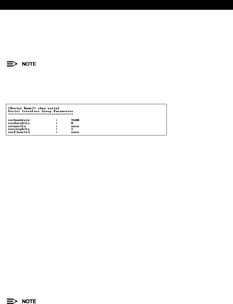
Command Line Interface (CLI)
109
Set Telnet Session Timeouts
[Device Name]>set tellogintout <time in seconds between 1 and 300 (default is 30)>
[Device Name]>set telsessiontout <time in seconds between 1 and 36000 (default is 900)>
Configure Serial Port Interface
To avoid unexpected performance issues, leave Flow Control at the default setting (none) unless you are sure
what this setting should be.
[Device Name]>set serbaudrate <2400, 4800, 9600, 19200, 38400, 57600>
[Device Name]>set serflowctrl <none, xon/xoff>
[Device Name]>show serial
Figure A-16 Result of “show serial” CLI Command
Configure Syslog
[Device Name]>set syslogpriority <1-7 (default is 6)>
[Device Name]>set syslogstatus <enable/disable>
Configure Intra BSS
[Device Name]>set intrabssoptype <passthru (default)/block)>
Configure MAC Access Control
Setup MAC (Address) Access Control
[Device Name]>set macaclstatus enable
[Device Name]>set macacloptype <passthru, block>
[Device Name]>reboot 0
Add an Entry to the MAC Access Control Table
[Device Name]>set macacltbl <index> macaddr <MAC Address> status enable
[Device Name]>show macacltbl
Disable or Delete an Entry in the MAC Access Control Table
[Device Name]>set macacltbl <index> status <disable/delete>
[Device Name]>show macacltbl
For larger networks that include multiple Access Points, you may prefer to maintain this list on a centralized
location using the RADIUS parameters (see Set RADIUS Parameters).
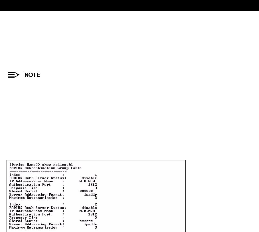
Command Line Interface (CLI)
110
Configure 802.1x Authentication
[Device Name]>set secconfig <none, 802.1x, mixed>
[Device Name]>set secenckeylentbl 3 enckeylen <64bits, 128bits, 152bits ( 1 5 2 b i t s
available with AP-600a only)>
[Device Name]>set secrekeyint <60 – 65535 seconds; default is 900 sec>
[Device Name]>reboot 0
If you set Security to 802.1x or Mixed, you also need to configure the RADIUS parameters. If you set Security
to Mixed, you also need to configure WEP Encryption settings. See 802.1x for details.
Set RADIUS Parameters
Configure RADIUS Authentication server
[Device Name]>set radiustbl <index> status enable seraddrfmt <ipaddr or name>
ipaddr <RADIUS IP address or name> port <user defined>
ssecret <user defined> responsetm <1 to 4 seconds>
maxretx <1 to 10 times>
[Device Name]>show radiustbl
Figure A-17 Results of “show radiustbl” CLI command
Enable RADIUS MAC Access Control
[Device Name]>set radmacaccctrl enable
[Device Name]>reboot 0
Set MAC Address Format Type
[Device Name]>set radmacaddrformat <dashdelimited, colondelimited, singledashdelimited,
nodelimiter>
Set Authentication Lifetime
[Device Name]>set radauthlifetm <60-43200 seconds; default is 900>
Enable RADIUS Accounting
[Device Name]>set radaccstatus enable
[Device Name]>set radaccinactivetmr <inactivity timer in minutes>
[Device Name]>show radius
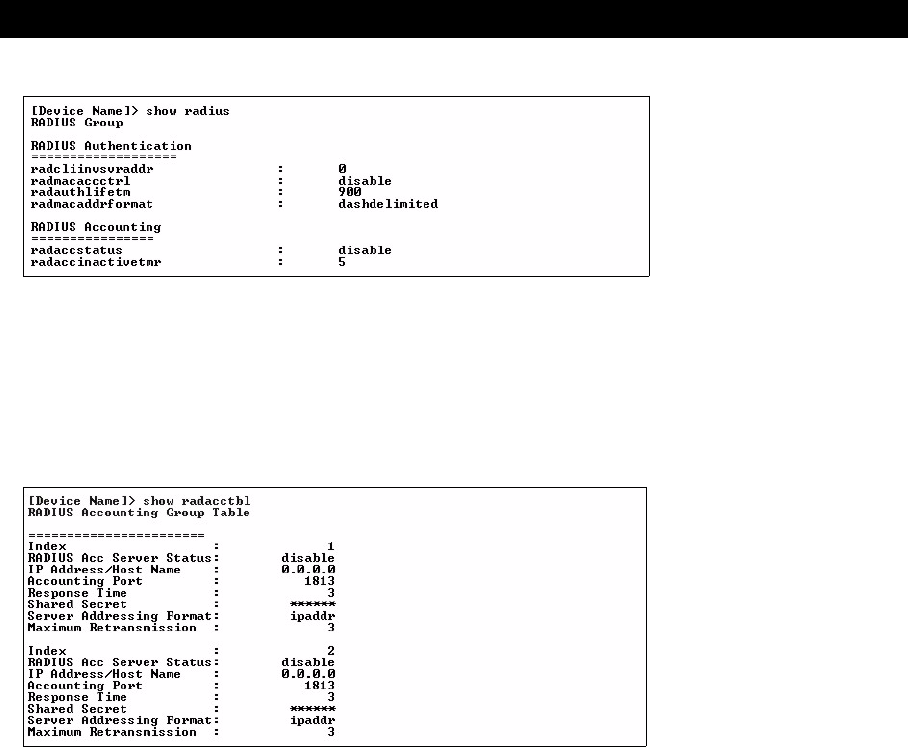
Command Line Interface (CLI)
111
Figure A-18 Result of “show radius” CLI Command
Configure RADIUS Accounting server
[Device Name]>set radacctbl <index> status <enable> seraddrfmt <ipaddr or name> ipaddr
<RADIUS IP address or name> port <user defined> ssecret <user defined>
responsetm <1 to 4 seconds> maxretx <1 to 10 times>
[Device Name]>show radacctbl
Figure A-19 Results of “show radacctbl” CLI command
CLI Monitoring Parameters
Using the show command with the following table parameters will display operating statistics for the AP-600 (these are
the same statistics that are described in Monitor Information for the HTTP Web interface).
–staticmp: Displays the ICMP Statistics.
–statarptbl: Displays the IP ARP Table Statistics.
–statbridgetbl: Displays the Learn Table.
–statiapp: Displays the IAPP Statistics.
–statradius: Displays the RADIUS Authentication Statistics.
–statif: Displays information and statistics about the Ethernet and wireless interfaces.
–stat802.11: Displays additional statistics for the wireless interfaces.
–statethernet: Displays additional statistics for the Ethernet interface.

Command Line Interface (CLI)
112
Parameter Tables
Objects contain groups that contain both parameters and parameter tables.
Use the following Tables to configure the Access Point. Columns used on the tables include:
—Name - Parameter, Group, or Table Name
—Type - Data type
—Values - Value range, and default value, if any
—Access = access type, R = Read Only (show), RW = Read-Write (can be “set”), W = Write Only
—CLI Parameter - Parameter name as used in the Access Point
Access Point network objects are associated with Groups. The network objects are listed below and associated
parameters are described in the following Parameter Tables:
•System Parameters - Access Point system information
–Inventory Management Information - Hardware, firmware, and software version information
•Network Parameters - IP and Network Settings
–IP Configuration Parameters - Configure the Access Point’s IP settings
—DNS Client for RADIUS Name Resolution - Configure the Access Point as a DNS client
–DHCP Server Parameters - Enable or disable dynamic host configuration
–Link Integrity Parameters - Monitor link status
•Interface Parameters - Configure Wireless and Ethernet settings
–Wireless Interface Parameters
—Wireless Distribution System (WDS) Parameters (AP-600b Only) - Configure the WDS partnerships
–Ethernet Interface Parameters - Set the speed and duplex of the Ethernet port
•Management Parameters - Control access to the AP-600’s management interfaces
–SNMP Parameters - Set read and read/write passwords
–HTTP (web browser) Parameters - Set up the graphical web browser interface
–Telnet Parameters - Telnet Port setup
–Serial Port Parameters - Serial Port setup
–TFTP Server Parameters - Set up for file transfers; specify IP Address, file name, and file type
–IP Access Table Parameters - Configure range of IP addresses that can access the AP-600
•Filtering Parameters
–Ethernet Protocol Filtering Parameters - Control network traffic based on protocol type
–Static MAC Address Filter Table - Enable and disable specific addresses
–Proxy ARP Parameters - Enable or disable proxy ARP for wireless clients
–IP ARP Filtering Parameters - Control which ARP messages are sent to wireless clients based on IP settings
–Broadcast Filtering Table - Control the type of broadcast packets forwarded to the wireless network
–TCP/UDP Port Filtering - Filter IP packets based on TCP/UDP port
•Alarms Parameters
–SNMP Table Host Table Parameters - Enter the list of IP addresses that will receive alarms from the AP-600
–Syslog Parameters - Configure the AP-600 to send Syslog information to network servers
•Bridge Parameters
–Spanning Tree Parameters - Used to help prevent network loops
–Storm Threshold Parameters - Set threshold for number of broadcast packets
–Intra BSS Subscriber Blocking - Enable or disable peer to peer traffic on the same AP
–Packet Forwarding Parameters - Redirect traffic from wireless clients to a specified MAC address
•Security Parameters - Access Point security settings
–Wireless Interface Security Parameters - Configure WEP encryption settings
–MAC Access Control Parameter - Control wireless access based on MAC address
•RADIUS Parameters
–Primary and Backup RADIUS Server Table Parameters - RADIUS Authentication and Accounting information
•Other Parameters
–IAPP Parameters - Enable or disable the Inter-Access Point Protocol
–SpectraLink VoIP Parameters (AP-600b Only) - Enable or disable SpectraLink Voice over IP feature

Command Line Interface (CLI)
113
System Parameters
Inventory Management Information
The inventory management commands display advanced information about the AP-600’s installed
components. You may be asked to report this information to a technical representative if you contact customer
support.
Network Parameters
IP Configuration Parameters
The IP Address Assignment Type (ipaddrtype) must be set to static before the IP Address (ipaddr), IP Mask
(ipmask) or Default Gateway IP Address (ipgw) values can be entered.
Name Type Values Access CLI Parameter
System Group N/A R system
Name DisplayString User Defined RW sysname
Location DisplayString User Defined RW sysloc
Contact Name DisplayString User Defined RW sysctname
Contact E-mail DisplayString User Defined RW sysctemail
Contact Phone DisplayString User Defined
max 254 characters
RW sysctphone
FLASH Backup Interval Integer 0 - 65535 seconds RW sysflashbckint
Flash Update 0
1
RW sysflashupdate
System OID DisplayString N/A R sysoid
Descriptor DisplayString System Name, flash
version, S/N, bootloader
version
R sysdescr
Up Time Integer dd:hh:mm:ss
dd – days
hh – hours
mm – minutes
ss – seconds
R sysuptime
Emergency Restore to defaults Resets all parameters to
default factory values
RW sysresettodefaults
Note: You must enter the
following command twice to
reset to defaults:
set sysresettodefaults 1
Name Type Values Access CLI Parameter
System Inventory Management Subgroup N/A R sysinvmgmt
Component Table Subgroup N/A R sysinvmgmtcmptbl
Component Interface Table Subgroup N/A R sysinvmgmtcmpiftbl
Name Type Values Access CLI Parameter
Network Group N/A R network
IP Configuration Group N/A R ip (Note: The network and
ip parameters display the
same information)
IP Address IpAddress User Defined RW ipaddr
IP Mask IpAddress User Defined RW ipmask
Default Router IP Address IpAddress User Defined RW ipgw
Default TTL Integer User Defined (seconds)
64 (default)
RW ipttl
Address Type Integer static
dynamic (default)
RW ipaddrtype

Command Line Interface (CLI)
114
DNS Client for RADIUS Name Resolution
DHCP Server Parameters
The DHCP Server (dhcpstatus) can only be enabled after a DHCP IP Pool table entry has been created.
DHCP Server table for IP pools
Set either End IP Address or Width (but not both) when creating an IP address pool.
Name Type Values Access CLI Parameter
DNS Client Group N/A R dns
DNS Client status Integer enable
disable (default)
RW dnsstatus
Primary DNS Server IP
Address
IpAddress User Defined RW dnspridnsipaddr
Secondary DNS Server
IP Address
IpAddress User Defined RW dnssecdnsipaddr
Default Domain Name Integer32 User Defined (up to 254
characters)
RW dnsdomainname
Name Type Values Access CLI Parameter
DHCP Server Group N/A R dhcp
DHCP Server Status Integer enable (1) (default)
disable (2)
delete (3)
RW dhcpstatus
Gateway IP Address IpAddress User Defined RW dhcpgw
Primary DNS IP Address IpAddress User Defined RW dhcppridnsipaddr
Secondary DNS IP
Address
IpAddress User Defined RW dhcpsecdnsipaddr
Number of IP Pool Table
Entries
Integer32 N/A R dhcpippooltblent
Name Type Values Access CLI Parameter
DHCP Server IP Address
Pool Table
Table N/A R dhcpippooltbl
Table Index Integer User Defined N/A index
Start IP Address IpAddress User Defined RW startipaddr
End IP Address IpAddress User Defined RW endipaddr
Width Integer User Defined RW width
Default Lease Time
(optional)
Integer32 > 0
86400 sec (default)
RW defleasetm
Maximum Lease Time
(optional)
Integer32 > 0
86400 sec (default)
RW maxleasetm
Comment (optional) DisplayString User Defined RW cmt
Status (optional) Integer enable (1)
disable (2)
delete (3)
RW status

Command Line Interface (CLI)
115
Link Integrity Parameters
Link Integrity IP Target Table
Interface Parameters
Wireless Interface Parameters
The wireless interface group parameter is wif. The interface uses table index 3.
Common Parameters to AP-600a and AP-600b
For AP-600a units in Europe, Auto Channel Select is a read-only parameter; it is always enabled.
Name Type Values Access CLI Parameter
Link Integrity Group N/A R linkint
Link Integrity Status Integer enable
disable (default)
RW linkintstatus
Link Integrity Poll
Interval
Integer 500 - 15000 ms
(in increments of 500ms)
500 ms (default)
RW linkintpollint
Link Integrity Poll
Retransmissions
Integer 0 - 255
5 (default)
RW linkintpollretx
Name Type Values Access CLI Parameter
Link Integrity IP Target
Table
Table N/A R linkinttbl
Table Index Integer 1-5 N/A index
Target IP Address IpAddress User Defined RW ipaddr
Comment (optional) DisplayString User Defined (up to 254
characters)
RW cmt
Status (optional) Integer enable
disable (default)
delete
RW status
Name Type Values Access CLI Parameter
Wireless Interfaces Group N/A R wif
Table Index Integer 3 R index
Network Name DisplayString 1 – 31 characters
My Wireless Network A
(default)
RW netname
Auto Channel Select (ACS) Integer enable (default)
disable
RW autochannel
DTIM Period Integer 1 – 65535
1 = default
RW dtimperiod
RTS/CTS Medium Reservation Integer 0 – 2347
Default is 2347 (off)
RW medres
MAC Address PhyAddress 12 hex digits R macaddr
Supported Frequency Channels Octet String Depends on Regulatory
Domain
R suppchannels

Command Line Interface (CLI)
116
AP-600a Only Parameters
AP-600b Only Parameters
Name Type Values Access CLI Parameter
Operating Frequency Channel Integer Varies by regulatory
domain and country. See
802.11a Channel
Frequencies for the
AP-600a
RW channel
2X Turbo Mode
(not available in all countries)
Integer enable
disable (default)
RW turbo
Supported Data Rates Octet String See Transmit Rate,
below
R suppdatarates
Transmit Rate Integer32 Reported in 500 Kb/sec
intervals:
0 - Auto Fallback
(default)
12 (6 Mbits/sec)
18 (9 Mbits/sec)
24 (12 Mbits/sec)
36 (18 Mbits/sec)
48 (24 Mbits/sec)
72 (36 Mbits/sec)
96 (48 Mbits/sec)
108 (54 Mbits/sec)
For Turbo mode (not
available in all
countries):
0 - Auto Fallback
(default)
24 (12 Mbits/sec)
38 (18 Mbits/sec)
48 (24 Mbits/sec)
72 (36 Mbits/sec)
96 (48 Mbits/sec)
144 (72 Mbits/sec)
192 (96 Mbits/sec)
216 (108 Mbits/sec)
RW txrate
Physical Layer Type Integer ofdm (orthogonal
frequency division
multiplexing) for 802.11a
R phytype
Regulatory Domain List DisplayString FCC (5.15-5.35 GHz,
5.725-5.850 GHz)
ETSI (5.15-5.25 GHz
only)
ETSI (5.15-5.35 GHz)
MMK (5.15-5.25 GHz)
Singapore (5.15-2.25
GHz, 5.725-5.850 GHz)
R regdomain
Name Type Values Access CLI Parameter
Distance between APs Integer large (default)
medium
small
minicell
microcell
RW distaps
Interference Robustness Integer enable (default)
disable
RW interrobust
Operating Frequency Channel Integer 1 - 14; available channels
vary by regulatory
domain/country; see
802.11b Channel
Frequencies for the
AP-600b
RW channel
Multicast Rate Integer 1 Mbits/sec (1)
2 Mbits/sec (2) (default)
5.5 Mbits/sec (3)
11 Mbits/sec (4)
RW multrate
Closed Wireless System Integer enable
disable (default)
RW closedsys

Command Line Interface (CLI)
117
There is an inter-dependent relationship between the Distance between APs and the Multicast Rate. In
general, larger systems operate a lower average transmit rates.
Wireless Distribution System (WDS) Parameters (AP-600b Only)
At this time, WDS is not available for the AP-600a.
Ethernet Interface Parameters
Load Balancing Integer enable (default)
disable
RW ldbalance
Medium Distribution Integer enable (default)
disable
RW meddendistrib
MAC Address PhyAddress 12 hex digits R macaddr
Supported Data Rates Octet String Reported in 500 Kb/sec
intervals:
2 (1 Mbits/sec)
4 (2 Mbits/sec) (default)
11 (5.5 Mbits/sec)
22 (11 Mbits/sec)
R suppdatarates
Transmit Rate Integer32 Reported in 500 Kb/sec
intervals:
0 (auto fallback - default)
2 (1 Mbits/sec)
4 (2 Mbits/sec)
11 (5.5 Mbits/sec)
22 (11 Mbits/sec)
RW txrate
Supported Frequency Channels Octet String Depends on Regulatory
Domain
R suppchannels
Physical Layer Type Integer dsss (direct sequence
spread spectrum) for
802.11b
R phytype
Regulatory Domain List DisplayString U.S./Canada -- FCC
Europe -- ETSI
Japan -- MKK
R regdomain
Distance between APs Multicast Rate
Large 1 and 2 Mbits/sec
Medium 1, 2, and 5.5 Mbits/sec
Small 1, 2, 5.5 and 11 Mbits/sec
Minicell 1, 2, 5.5 and 11 Mbits/sec
Microcell 1, 2, 5.5 and 11 Mbits/sec
Name Type Values Access CLI Parameter
WDS Table Table N/A R wdstbl
Port Index Integer 3.1 - 3.6 (Wireless) R portindex
Status Integer enable, disable RW status
Partner MAC Address PhysAddress User Defined RW partnermacaddr
Name Type Values Access CLI Parameter
Ethernet Interface Group N/A R ethernet
Speed Integer 10halfduplex
10fullduplex
10autoduplex
100halfduplex
100fullduplex
autohalfduplex
autoautoduplex (default)
RW etherspeed
MAC Address PhyAddress N/A R ethermacaddr
Name Type Values Access CLI Parameter

Command Line Interface (CLI)
118
Management Parameters
SNMP Parameters
HTTP (web browser) Parameters
The default path for the Help files is
C:\Program Files\ORiNOCO\AP600\Help\English\index.htm
. The
ORiNOCO AP-600 Help information is available in English, French, German, Italian, Spanish, and Japanese.
The Help files are copied to your computer in all six languages. To update the Help link to use a different
language, enter the appropriate path in the Help Link box. For example, to change to the French Help file, use
the following path:
C:\Program Files\ORiNOCO\AP600\Help\French\index.htm
.
Telnet Parameters
Name Type Values Access CLI Parameter
SNMP Group N/A R snmp
SNMP Management
Interface Bitmask
Interface Bitmask 0 or 2 - no interfaces
(disable)
1 or 3 - Ethernet
4 or 6 - Wireless
5 or 7 - all interfaces
(default is 7)
RW snmpifbitmask
Read Password DisplayString User Defined
public (default)
max 63 characters
W snmprpasswd
Read/Write Password DisplayString User Defined
public (default)
max 63 characters
W snmprwpasswd
Name Type Values Access CLI Parameter
HTTP Group N/A R http
HTTP Management
Interface Bitmask
Interface Bitmask 0 or 2 - no interfaces
(disable)
1 or 3 - Ethernet
4 or 6 - Wireless
5 or 7 - all interfaces
(default is 7)
RW httpifbitmask
HTTP Password DisplayString User Defined
max 64 characters
W httppasswd
HTTP Port Integer User Defined
Default = 80
RW httpport
Help Link DisplayString User Defined RW httphelplink
Name Type Values Access CLI Parameter
Telnet Group N/A R telnet
Telnet Management
Interface Bitmask
Interface Bitmask 0 or 2 - no interfaces
(disable)
1 or 3 - Ethernet
4 or 6 - Wireless
5 or 7 - all interfaces
(default is 7)
RW telifbitmask
Telnet Port Integer User Defined
23 (default)
RW telport
Telnet Login Inactivity
Time-out
Integer 1 – 60 seconds
30 sec (default)
RW tellogintout
Telnet Session Idle
Time-out
Integer 1 - 900 seconds
900 sec (default)
RW telsessiontout

Command Line Interface (CLI)
119
Serial Port Parameters
TFTP Server Parameters
These parameters relate to upload and download commands.
When a user executes an upload and/or download Command, the specified arguments are stored in TFTP parameters
for future use. If nothing is specified in the command line when issuing subsequent upload and/or download
commands, the stored arguments are used.
IP Access Table Parameters
When creating table entries, you may either specify the argument name followed by argument value or simply entering
the argument value. When only the argument value is specified, then enter the values in the order depicted by the
following table. CLI applies default values to the omitted arguments. Due to the nature of the information, the only
argument that can be omitted is the “comment” argument.
Filtering Parameters
Ethernet Protocol Filtering Parameters
Name Type Values Access CLI Parameter
Serial Group N/A R serial
Baud Rate Integer 2400, 4800,
9600 (default),
19200, 38400, 57600
RW serbaudrate
Data Bits Integer 8 R serdatabits
Parity Integer none R serparity
Stop Bits Integer 1 R serstopbits
Flow Control Value none (default)
xon/xoff
RW serflowctrl
Name Type Values Access CLI Parameter
TFTP Group N/A R tftp
TFTP Server IP Address IpAddress User Defined RW tftpipaddr
TFTP File Name DisplayString User Defined RW tftpfilename
TFTP File Type Integer img
config
bootloader
RW tftpfiletype
Name Type Values Access CLI Parameter
IP Access Table Table N/A R mgmtipaccesstbl
Table Index Integer User Defined N/A index
IP Address IpAddress User Defined RW ipaddr
IP Mask IpAddress User Defined RW ipmask
Comment (optional) DisplayString User Defined RW cmt
Status (optional) Integer enable (default)
disable
delete
RW status
Name Type Values Access CLI Parameter
Ethernet Filtering Group N/A R etherflt
Filtering Interface
Bitmask
Interface Bitmask 0 or 2 - no interfaces
(disable)
1 or 3 - Ethernet
4 or 6 - Wireless
5 or 7 - all interfaces
(default is 7)
RW etherfltifbitmask
Operation Type passthru
block
RW etherfltoptype

Command Line Interface (CLI)
120
Ethernet Filtering Table
Identify the different filters by using the table index.
The filter Operation Type (passthru or block) applies only to the protocol filters that are enabled in this table.
Static MAC Address Filter Table
Proxy ARP Parameters
IP ARP Filtering Parameters
Name Type Values Access CLI Parameter
Ethernet Filtering Table Table N/A R etherflttbl
Table Index N/A N/A R index
Protocol Number Octet String N/A RW protonumber
Protocol Name (optional) DisplayString RW protoname
Filter Comment DisplayString 2- 31 characters RW cmt
Status (optional) Integer enable (1)
disable (2)
delete (3)
RW status
Name Type Values Access CLI Parameter
Static MAC Address
Filter Table
Table N/A R staticmactbl
Table Index N/A N/A R index
Static MAC Address on
Wired Network
PhysAddress User Defined RW wiredmacaddr
Static MAC Address
Mask on Wired Network
PhysAddress User Defined RW wiredmask
Static MAC Address on
Wireless Network
PhysAddress User Defined RW wirelessmacaddr
Static MAC Address
Mask on Wireless
Network
PhysAddress User Defined RW wirelessmask
Comment (optional) DisplayString max 255 characters RW cmt
Status (optional) Integer enable (default)
disable
delete
RW status
Name Type Values Access CLI Parameter
Proxy ARP Group N/A R parp
Status Integer enable
disable (default)
RW parpstatus
Name Type Values Access CLI Parameter
IP ARP Filtering Group N/A R iparp
Status Integer enable
disable (default)
RW iparpfltstatus
IP Address IpAddress User Defined RW iparpfltipaddr
Subnet Mask IpAddress User Defined RW iparpfltsubmask

Command Line Interface (CLI)
121
Broadcast Filtering Table
TCP/UDP Port Filtering
The following parameters are used to enable/disable the Port filter feature.
TCP/UDP Port Filtering Table
The following parameters are used to configure TCP/UDP Port filters.
Name Type Values Access CLI Parameter
Broadcast Filtering
Table
Table N/A R broadcastflttbl
Index Integer 1-5 N/A index
Protocol Name DisplayString N/A R protoname
Direction Integer ethertowireless
wirelesstoether
both (default)
RW direction
Status Integer enable
disable (default)
RW status
Name Type Values Access CLI
Port Filtering Group N/A R portflt
Port Filter Status Integer enable (default)
disable
RW portfltstatus
Name Type Values Access CLI
Port Filtering Table Table N/A R portflttbl
Table Index N/A User Defined
(there are also 4
pre-defined indices, see
Port Number below for
more information)
R index
Port Type Octet String TCP
UDP
TCP/UDP
RW porttype
Port Number Octet String User Defined
(there are also 4
pre-defined protocols:
Index 1: NetBios Name
Service – 137, Index 2:
NetBios Datagram
Service – 138, Index 3:
NetBios Session
Service – 139, Index 4:
SNMP Service – 161)
RW portnum
Protocol Name DisplayString User Defined
(there are also 4
pre-defined protocols,
see Port Number above)
RW protoname
Interface Bitmask Integer32 0 or 2 - no interfaces
(disable)
1 or 3 - Ethernet
4 or 6 - Wireless
5 or 7 - all interfaces
(default is 7)
RW ifbitmask
Status (optional) Integer enable (default for new
entries)
disable (default for
pre-defined entries)
delete
RW status

Command Line Interface (CLI)
122
Alarms Parameters
SNMP Table Host Table Parameters
When creating table entries, you may either specifying the argument name followed by argument value. CLI applies
default values to the omitted arguments. Due to the nature of the information, the only argument that can be omitted is
the “comment” argument.
Syslog Parameters
The following parameters configure the Syslog settings.
The Heartbeat parameters are advanced settings not available via the HTTP interface. When Heartbeat is
enabled, the AP-600 periodically sends a message to the Syslog server to indicate that it is active. The
frequency with which the heartbeat message is sent depends upon the setting of the Heartbeat Interval.
Syslog Host Table
The table described below configures the Syslog hosts that will receive message from the AP-600. You can configure
up to ten Syslog hosts.
Name Type Values Access CLI Parameter
SNMP Trap Host Table Table N/A R snmptraphosttbl
Table Index Integer User Defined N/A index
IP Address IpAddress User Defined RW ipaddr
Password DisplayString User Defined (up to 64
characters)
W passwd
Comment (optional) DisplayString User Defined (up to 254
characters)
RW cmt
Status (optional) Integer enable (default)
disable
delete
RW status
Name Type Values Access CLI
Syslog Group N/A R syslog
Syslog Status Integer enable
disable (default)
RW syslogstatus
Syslog Port Octet String 514 R syslogport
Syslog Lowest Priority
Logged
Integer 1 – 7
1 = LOG_ALERT
2 = LOG_CRIT
3 = LOG_ERR
4 = LOG_WARNING
5 = LOG_NOTICE
6 = LOG_INFO (default)
7 = LOG_DEBUG
RW syslogpritolog
Heartbeat Status Integer enable (1)
disable (2) (default)
RW heartbeatstatus
Heartbeat Interval (seconds) Integer 1 – 604800 seconds;
900 sec. (default)
RW heartbeatinterval
Name Type Values Access CLI Parameter
Syslog Host Table Table N/A R sysloghosttbl
Table Index Integer 1 – 10 N/A index
IP Address IpAddress User Defined RW ipaddr
Comment (optional) DisplayString User Defined RW cmt
Status (optional) Integer enable
disable
delete
RW status

Command Line Interface (CLI)
123
Bridge Parameters
Spanning Tree Parameters
Spanning Tree Priority and Path Cost Table
Storm Threshold Parameters
Storm Threshold Table
Name Type Values Access CLI Parameter
Spanning Tree Group N/A R stp
Spanning Tree Status Integer enable
disable (default)
RW stpstatus
Bridge Priority Integer 0 – 65535
32768 (default)
RW stppriority
Maximum Age Integer 600 – 4000
(in 0.01 sec intervals;
i.e., 6 to 40 seconds)
2000 (default)
RW stpmaxage
Hello Time Integer 100 – 1000
(in 0.01 sec intervals;
i.e., 1 to 10 seconds)
200 (default)
RW stphellotime
Forward Delay Integer 400 – 3000
(in 0.01 sec intervals;
i.e., 4 to 30 seconds)
1500 (default)
RW stpfwddelay
Name Type Values Access CLI Parameter
Spanning Tree Table Table N/A R stpbl
Table Index (Port) N/A 1 – 15 R index
Priority Integer 0 – 255
128 (default)
RW priority
Path Cost Integer 1 – 65535
100 (default)
RW pathcost
State Integer disable
blocking
listening
learning
forwarding
broken
Rstate
Status Integer enable
disable
RW status
Name Type Values Access CLI Parameter
Storm Threshold Group N/A N/A stmthres
Broadcast Threshold Integer 0 – 255 packets/sec
(default is 0)
RW stmbrdthres
Multicast Threshold Integer 0 – 255 packets/sec
(default is 0)
RW stmmultithres
Name Type Values Access CLI Parameter
Storm Threshold Table Table N/A R stmthrestbl
Table Index Integer 1 = Ethernet
3 = Wireless
R index
Broadcast Threshold Integer 0 – 255 packets/sec
(default is 0)
RW bcast
Multicast Threshold Integer 0 – 255 packets/sec
(default is 0)
RW mcast

Command Line Interface (CLI)
124
Intra BSS Subscriber Blocking
The following parameters control the Intra BSS traffic feature, which prevent wireless clients that are associated with
the same AP-600 from communicating with each other:
Packet Forwarding Parameters
The following parameters control the Packet Forwarding feature, which redirects wireless traffic to a specific MAC
address:
The Wireless Distribution System (WDS) feature is not available for the AP-600a at this time.
Security Parameters
Wireless Interface Security Parameters
The following table details the WEP encryption parameters for the AP-600 (both the AP-600a and the AP-600b).
Name Type Values Access CLI
Intra BSS Traffic Group N/A R intrabss
Intra BSS Traffic
Operation
Integer passthru (default)
block
RW intrabssoptype
Name Type Values Access CLI
Packet Forwarding MAC
Address
Group N/A R pktfwd
Packet Forwarding MAC
Address
MacAddress User Defined RW pktfwdmacaddr
Packet Forwarding
Status
Integer enable
disable (default)
RW pktfwdstatus
Packet Forwarding
Interface Port
Integer 0 (any) (default)
1 (Ethernet)
3 (WDS 1)
4 (WDS 2)
5 (WDS 3)
6 (WDS 4)
7 (WDS 5)
8 (WDS 6)
RW pktfwdif
Name Type Values Access CLI Parameter
Security Group N/A R security
Configuration Mode Integer none (default)
802.1x
mixed
RW secconfig
Re-keying Interval Integer 60 – 65535 seconds
default is 900 sec
RW secrekeyint
Name Type Values Access CLI Parameter
Wireless Interfaces
Security
Group R wifsec
Encryption Status Integer enable
disable (default)
RW encryptstatus
Index Integer 3 R index
Encryption Key 1 DisplayString User Defined W encryptkey1
Encryption Key 2 DisplayString User Defined W encryptkey2
Encryption Key 3 DisplayString User Defined W encryptkey3
Encryption Key 4 DisplayString User Defined W encryptkey4
Deny non-encrypted
Data
Integer enable (default)
disable
RW encryptdeny
Data Transmission
Encryption Key
Integer 1 (default)
2
3
4
RW encryptkeytx

Command Line Interface (CLI)
125
See WEP Encryption for information on the supported WEP Key lengths.
Security Encryption Key Length Table
The following table details how to set the Encryption Key Length for the wireless interfaces.
The available Encryption Key Lengths vary based on model. The AP-600a supports 64, 128, or 152 bits. The
AP-600b supports 64 bits or 128 bits.
MAC Access Control Parameter
MAC Access Control Table
RADIUS Parameters
Primary and Backup RADIUS Server Table Parameters
ORiNOCO devices that use RADIUS authentication and/or accounting support both primary and backup RADIUS
servers. The configuration parameters and statistics are the same for both primary and backup servers. The CLI
differentiates the primary and backup RADIUS parameters by using the table index.
General RADIUS Parameters
Name Type Values Access CLI Parameter
Security Encryption Key
Length Table
Table N/A R secenckeylentbl
Index Integer 3 N/A index
Encryption Key Length Integer 64 bit
128 bit
152 bit
RW enckeylen
Name Type Values Access CLI Parameter
MAC Address Control Group N/A R macacl
Status Integer enable
disable (default)
RW macaclstatus
Operation Type Integer passthru (default)
block
RW macacloptype
Name Type Values Access CLI Parameter
MAC Address Control
Table
Table N/A R macacltbl
Table Index N/A N/A R index
MAC Address PhysAddress User Defined RW macaddr
Comment (optional) DisplayString User Defined
max 254 characters
RW cmt
Status (optional) Integer enable (default)
disable
RW status
Name Type Values Access CLI Parameter
RADIUS Group N/A R radius
MAC Access Control
Status
Integer enable
disable (disable)
R radmacacctrl
Authorization Lifetime Integer32 60 – 43200 seconds
900 sec. (default)
RW radauthlifetm
MAC Address Format Integer dashdelimited (default)
colondelimited
singledashdelimited
no delimiter
RW radmacaddrformat

Command Line Interface (CLI)
126
RADIUS Authentication
Use a server name only if you have enabled the DNS Client functionality. See DNS Client for RADIUS Name
Resolution.
RADIUS Accounting
Use a server name only if you have enabled the DNS Client functionality. See DNS Client for RADIUS Name
Resolution.
RADIUS Accounting
Status
Integer enable
disable (disable)
RW radaccstatus
Accounting Inactivity
Timer
Integer32 0 – 2147483647
minutes; default is 5 min.
RW radaccinactivetmr
Name Type Values Access CLI Parameter
RADIUS Authentication Table N/A R radiustbl
Primary RADIUS Integer 1 R index
Backup RADIUS Integer 2 R index
RADIUS Server Status Integer enable
disable (default)
RW status
Server Addressing
Format (see note)
Integer ipaddr (default)
name
RW seraddrfmt
Server IP Address or
Name
IpAddress
DisplayString
User Defined
(enter an IP address if
seraddrfmt is ipaddr or a
name if set to name; up
to 254 characters if
using a name)
RW ipaddr
Port (optional) Integer User Defined
1812 (default)
RW port
Shared Secret DisplayString User Defined
max 63 characters
W ssecret
Response Time (sec) Integer 1 – 4 seconds
3 sec (default)
RW responsetm
Maximum
Retransmissions
(optional)
Integer 1 – 10
3 (default)
RW maxretx
Name Type Values Access CLI Parameter
RADIUS Accounting Table N/A R radacctbl
Primary RADIUS Integer 1 R index
Backup RADIUS Integer 2 R index
RADIUS Server Status Integer enable
disable (default)
RW status
Server Addressing
Format (see note)
Integer ipaddr (default)
name
RW seraddrfmt
Server IP Address or
Name
IpAddress
Display String
User Defined
(enter an IP address if
seraddrfmt is ipaddr or a
name if set to name; up
to 254 characters if
using a name)
RW ipaddr
Port (optional) Integer User Defined
1813 (default)
RW port
Shared Secret DisplayString User Defined
max 63 characters
W ssecret
Response Time (sec) Integer 1 – 4 seconds
3 sec (default)
RW responsetm
Maximum
Retransmissions
(optional)
Integer 1 – 10
3 (default)
RW maxretx

Command Line Interface (CLI)
127
Other Parameters
IAPP Parameters
These parameters configure the Inter Access Point Protocol (IAPP) for roaming. Leave these settings at their
default value unless a technical representative asks you to change them.
SpectraLink VoIP Parameters (AP-600b Only)
Name Type Values Access CLI Parameter
IAPP Group N/A R iapp
IAPP Status Integer enable (default)
disable
RW iappstatus
Periodic Announce
Interval (seconds)
Integer 80
120 (default)
160
200
RW iappannint
Announce Response
Time
Integer 2 seconds R iappannresp
Handover Time-out Integer 410 ms
512 ms (default)
614 ms
717 ms
819 ms
RW iapphandtout
Max. Handover
Retransmissions
Integer 1 - 10 (default 4) RW iapphandretx
Send Announce
Request on Startup
Integer enable (default)
disable
RW iappannreqstart
Name Type Values Access CLI Parameter
Spectralink VoIP Group N/A R spectralink
Spectralink VoIP Status Integer enable
disable (default)
RW speclinkstatus

128
B
ASCII Character Chart
You can configure WEP Encryption Keys in either Hexadecimal or ASCII format. Hexadecimal digits are 0-9 and A-F
(not case sensitive). ASCII characters are 0-9, A-F, a-f (case sensitive), and punctuation marks. Each ASCII character
corresponds to two hexadecimal digits.
The table below lists the ASCII characters that you can use to configure WEP Encryption Keys. It also lists the
Hexadecimal equivalent for each ASCII character.
ASCII
Character
Hex
Equivalent
ASCII
Character
Hex
Equivalent
ASCII
Character
Hex
Equivalent
ASCII
Character
Hex
Equivalent
!21 939 Q51 i69
"22 :3A R52 j6A
#23 ;3B S53 k6B
$24 <3C T54 l6C
%25 =3D U55 m6D
&26 >3E V56 n6E
'27 ?3F W57 o6F
(28 @40 X58 p70
)29 A41 Y59 q71
*2A B42 Z5A r72
+2B C43 [5B s73
,2C D44 \5C t74
-2D E45 ]5D u75
.2E F46 ^5E v76
/2F G47 _5F w77
030 H48 `60 x78
131 I49 a61 y79
232 J4A b62 z7A
333 K4B c63 {7B
434 L4C d64 |7C
535 M4D e65 }7D
636 N4E f66 ~7E
737 O4F g67
838 P50 h68
129
C
Specifications
In This Appendix
•Hardware Specifications
•Radio Specifications
Hardware Specifications
Physical Specifications
AP-600 Unit (without metal base)
Dimensions (H x W x L) = 3.5 x 17 x 21.5 cm (1.5 x 6.75 x 8.5 in.)
Weight = 0.68 kg (1.50 lb.)
Electrical Specifications
Using the Power Adapter
Voltage (Input) = 100 to 240 VAC (50-60 Hz) @ 0.4 A
Voltage (Output) = 12 VDC
Power Consumption = 10 Watts
Using Active Ethernet
Input Voltage = 42 to 60 VDC
Output Current = 200mA at 48V
Power Consumption = 10 Watts
Environmental Specifications
AP-600 Unit
Operating Temperature = 0° to +55°C ambient temperature (without plastic cabinet)
Operating Humidity = 95% maximum (non condensing)
Storage Temperature = -20 to +75°C ambient temperature
Storage Humidity = 95% maximum (non condensing)
Ethernet Interface
10/100 Base-TX, RJ-45 female socket
Serial Port Interface
Standard RS-232C interface with DB-9, female connector

Specifications
130
Active Ethernet Interface
Category 5, foiled, twisted pair cables must be used to ensure compliance with FCC Part 15, subpart B,
Class B requirements
Standard 802.3af pin assignments
HTTP Interface
Microsoft Internet Explorer 5.5 or later (preferred), or Netscape 4.x or later.
Radio Specifications
For AP-600a: 802.11a radio certification is available in the U.S. (FCC), Canada (DOC), Japan (MKK), Europe (ETSI),
Singapore, and Australia.
For AP-600b: 802.11b radio certification is available in the U.S. (FCC), Canada (DOC), Japan (MKK), Europe (ETSI),
Australia, and South Africa.
Refer to the Regulatory Flyer included with the AP-600 for the latest regulatory information.
802.11a Channel Frequencies for the AP-600a
The available 802.11a Channels varies by regulatory domain and/or country.
FCC (U.S., Canada, Australia)
The AP-600a can operate on the following Channels in the FCC regulatory domain:
Channels 42, 50, 58, 152, and 160 are the available Channels when 2X Turbo mode is enabled. These
Channels are unavailable when 2X Turbo mode is disabled.
ETSI (Europe)
Some European countries restrict 802.11a operation to the 5.15-5.25 GHz frequency band. Other European countries
restrict 802.11a operation to the 5.15-5.35 GHz frequency band.
The AP-600a can operate on the following Channels in the European countries that allow operation in the
5.15-5.25 GHz band:
Channel ID Center Frequency
(GHz)
Channel ID Center Frequency
(GHz)
36 5.180 60 5.300
40 5.200 64 5.320
42 (see note) 5.210 149 5.745
44 5.220 152 (see note) 5.760
48 5.240 153 5.765
50 (see note) 5.250 157 5.785
52 5.260 160 (see note) 5.800
56 5.280 161 5.805
58 (see note) 5.290 165 5.825
Channel ID Center Frequency
(GHz)
36 5.180
40 5.200
44 5.220
48 5.240
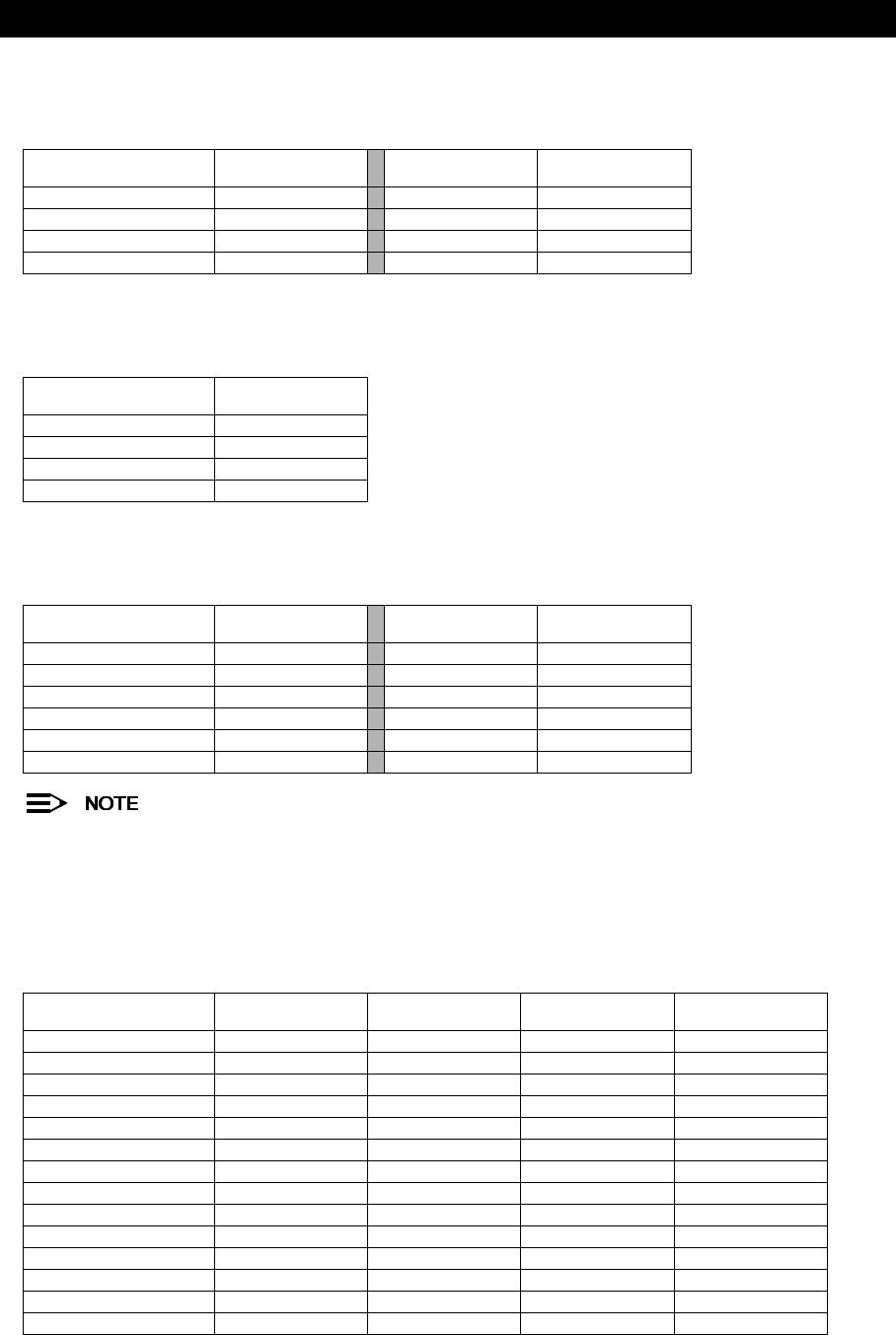
Specifications
131
The AP-600a can operate on the following Channels in the European countries that allow operation in the
5.15-5.25 GHz band:
Japan (MKK)
The AP-600a can operate on the following Channels in Japan:
Singapore
The AP-600a can operate on the following Channels in Singapore:
Channels 42, 152, and 160 are the available Channels when 2X Turbo mode is enabled. These Channels are
unavailable when 2X Turbo mode is disabled.
802.11b Channel Frequencies for the AP-600b
The following table shows the 802.11b channel allocations that vary from country to country.
Channel ID Center Frequency
(GHz)
Channel ID Center Frequency
(GHz)
36 5.180 52 5.260
40 5.200 56 5.280
44 5.220 60 5.300
48 5.240 64 5.320
Channel ID Center Frequency
(GHz)
34 5.170
38 5.190
42 5.210
46 5.230
Channel ID Center Frequency
(GHz)
Channel ID Center Frequency
(GHz)
36 5.180 152 (see note) 5.760
40 5.200 153 5.765
42 (see note) 5.210 157 5.785
44 5.220 160 (see note) 5.800
48 5.240 161 5.805
149 5.745 165 5.825
Channel ID FCC/World
(GHz)
ETSI
(GHz)
France
(GHz)
Japan
(GHz)
1 2.412 2.412 - 2.412
2 2.417 2.417 - 2.417
3 2.422 2.422 - 2.422
4 2.427 2.427 - 2.427
5 2.432 2.432 - 2.432
6 2.437 2.437 - 2.437
7 2.442 2.442 - 2.442
8 2.447 2.447 - 2.447
9 2.452 2.452 - 2.452
10 2.457 2.457 2.457 2.457
11 2.462 2.462 2.462 2.462
12 - 2.467 2.467 2.467
13 - 2.472 2.472 2.472
14 2.484

Specifications
132
Wireless Communication Range
The range of the wireless signal is related to the composition of objects in the radio wave path and the transmit rate of
the wireless communication. Communications at a lower transmit range may travel longer distances. The range values
listed in the Communications Range Chart are typical distances as calculated by Proxim’s development team for
FCC-certified products. These values provide a rule of thumb and may vary according to the actual radio conditions at
the location where the product is used.
The range of your wireless devices can be affected when the antennas are placed near metal surfaces and solid
high-density materials. Range is also impacted due to “obstacles” in the signal path of the radio that may either absorb
or reflect the radio signal.
In Open Office environments, antennas can “see” each other (no physical obstructions between them). In Semi-open
Office environments, workspace is divided by shoulder-height, hollow wall elements; antennas are at desktop level. In
a Closed Office environment, solid walls and other obstructions may affect signal strength.
The following tables show typical range values for various environments for FCC-certified products (range may differ
for products certified in other regulatory domains).
AP-600a
Table C-1 AP-600a: 802.11a Wireless communication ranges
The typical range values for 2X Turbo mode are similar to the values listed above. For example, the operating
range at 108 Mbits/sec in 2X Turbo mode is similar to the operating range at 54 Mbits/sec in 802.11a mode.
AP-600b
Table C-2 AP-600b: 802.11b Wireless communication ranges
Range 54 Mbits/s 54 Mbits/s 36 Mbits/s 24 Mbits/s 18 Mbits/s 12 Mbits/s 9 Mbits/s 6 Mbits/s
Open Office 44 m
(144 ft.)
67 m
(220 ft.)
102 m
(335 ft.)
155 m
(508 ft.)
212 m
(695 ft.)
261 m
(856 ft.)
290 m
(951 ft.)
321 m
(1053 ft.)
Semi-Open Office 29 m
(95 ft.)
42 m
(138 ft.)
60 m
(197 ft.)
85 m
(279 ft.)
111 m
(364 ft.)
132 m
(433 ft.)
145 m
(475 ft.)
158 m
(518 ft.)
Closed Office 21 m
(69 ft.)
28 m
(92 ft.)
37 m
(121 ft.)
49 m
(161 ft.)
61 m
(200 ft.)
71 m
(233 ft.)
76 m
(250 ft.)
82 m
(269 ft.)
Receiver Sensitivity -69 dBm -73 dBm -77 dBm -81 dBm -84 dBm -86 dBm -87 dBm -88 dBm
Range 11 Mbits/s 5.5 Mbits/s 2 Mbits/s 1 Mbits/s
Open Office 253 m
(830 ft.)
347 m
(1138 ft.)
475 m
(1558 ft.)
650 m
(2132 ft.)
Semi-Open Office 129 m
(423 ft.)
168 m
(551 ft.)
220 m
(722 ft.)
286 m
(938 ft.)
Closed Office 69 m
(226 ft.)
86 m
(282 ft.)
107 m
(351 ft.)
132 m
(433 ft.)
Receiver Sensitivity -82 dBm -85 dBm -88 dBm -91 dBm

133
D
Technical Support
If you are having a problem using an AP-600 and cannot resolve it with the information in Troubleshooting, gather the
following information and contact ORiNOCO Technical Support:
•List of ORiNOCO products installed on your network; include the following:
–Product names and quantity
–Part numbers (P/N)
–Serial numbers (S/N)
•List of ORiNOCO software versions installed
–For the AP-600, check the HTTP interface’s Version screen
–Include the source of the software version (e.g., pre-loaded on unit, installed from CD, downloaded from
Proxim Web site, etc.)
•Information about your network
–Network operating system (e.g., Microsoft Networking); include version information
–Protocols used by network (e.g., TCP/IP, NetBEUI, IPX/SPX, AppleTalk)
–Ethernet frame type (e.g., 802.3, Ethernet II), if known
–IP addressing scheme (include address range and whether static or DHCP)
–Network speed and duplex (10 or 100 Mbits/sec; full or half duplex)
–Type of Ethernet device that the Access Points are connected to (e.g., Active Ethernet power injector, hub,
switch, etc.)
–Type of Security enabled on the wireless network (None, WEP Encryption, 802.1x, Mixed)
•A description of the problem you are experiencing
–What were you doing when the error occurred?
–What error message did you see?
–Can you reproduce the problem?
–For each ORiNOCO product, describe the behavior of the device’s LEDs when the problem occurs
You can reach ORiNOCO Technical Support by phone or e-mail, as described below.
The latest software and documentation is available for download at http://www.proxim.com/support/.
For the U.S. and Canada:
Phone: 1-866-ORiNOCO (1-866-674-6626)
E-mail: USAsupport@orinocowireless.com
For the Caribbean and Latin America:
Phone: 1-866-ORiNOCO (1-866-674-6626)
1-661-367-2230
E-mail: CALAsupport@orinocowireless.com

Technical Support
134
For Asia Pacific:
Phone: +1 661-367-2230
E-mail: APACsupport@orinocowireless.com
For Europe, the Middle East, and Africa (EMEA):
Your local supplier in the EMEA region is trained to give you the support you require. Local suppliers have direct
access to the ORiNOCO Technical Support Center and will help you in every way they can.
Phone: +1 661-367-2230
E-mail: EMEAsupport@orinocowireless.com

USA/Canada section from the products regulatory flyer:
INFORMATION TO THE USER
This document provides regulatory information for the following products:
Wireless Base Station products such as the AP- 600
Base Station products are wireless network products based on IEEE 802.11 standards for wireless LANs as defined and
approved by the Institute of Electrical and Electronics Engineers. Products designed according the IEEE 802.11a standard
use Orthogonal Frequency Division Multiplexing (OFDM) radio technology. Products designed according the
IEEE 802.11b standard use Direct Sequence Spread Spectrum (DSSS) radio technology. These products are designed to
be interoperable with any other wireless product that complies with the corresponding standard.
• Wireless Fidelity (WiFi) certification is defined by the WECA Wireless Ethernet Compatibility Alliance.
IMPORTANT SAFETY INSTRUCTIONS
When using this device, basic safety precautions should always be followed to reduce the risk of fire, electric shock and
injury to persons, including the following:
a. Do not use this product near water, for example, near a bathtub, washbowl, kitchen sink or laundry tub, in a wet
basement or near a swimming pool.
b. Avoid using this product during an electrical storm. There may be a remote risk of electric shock from lightning.
c. Do not use this product to report a gas leak in the vicinity of the leak.
Additional Installation Requirements for Base Station products
When installing Base Stations the placement of the device must also satisfy the following installation requirements:
a. Connect the unit to a grounding type AC wall outlet (100-240 V AC) using only the standard power cord/adapter
provided with the product.
b. Placement must allow the user to easily disconnect the power cord/adapter of the device from the AC wall-outlet.
c. Do not cover the device, or block the airflow to the device with any other objects. Keep the device away from
excessive heat and humidity and keep the device free from vibration and dust.
d. Installation must at all times conform to local regulations.
e. Always disconnect the cables before opening the equipment enclosure or touching an uninsulated cable, jack or
internal component.
f. Connections to Base Station products can be made with either Unshielded Twisted Pair (UTP) or Shielded Twisted
Pair cabling (STP) cabling. When using the device in combination with Power over Ethernet, only use Shielded
Twisted Pair cabling (STP).
SAVE THESE INSTRUCTIONS
Wireless LAN and your Health
Wireless LAN products, like other radio devices, emit radio frequency electromagnetic energy. The level of emitted energy
however is far less than the electromagnetic energy emitted by other wireless devices such as mobile phones, for
example. Because Wireless LAN products operate within the guidelines found in radio frequency safety standards and
recommendations, we believe that our Wireless LAN products are safe for use by consumers. These standards and
recommendations reflect the consensus of the scientific community and result from deliberations of panels and
committees of scientists who continually review and interpret the extensive research literature.
Regulatory Information
This device must be installed and used in strict accordance with the manufacturer's instructions as described in the user
documentation that comes with the product.
For country-specific radio approvals or restrictions, please consult section ‘Radio Approvals’ of this flyer.
In some situations or environments, the use of wireless devices may be restricted by the proprietor of the building or
responsible representatives of the organization. For example, these situations may include:
• Using the wireless equipment on board of airplanes, or
• In any other environment where the risk of interference to other devices or services is perceived or identified as
harmful.
If you are uncertain of the policy that applies to the use of wireless equipment in a specific organization or environment
(e.g., airports), you are encouraged to ask for authorization to use this device prior to turning on the equipment. The
manufacturer is not responsible for any radio or television interference caused by unauthorized modification of the devices
included with this kit, or the substitution or attachment of connecting cables and equipment other than specified by
manufacturer. The correction of interference caused by such unauthorized modification, substitution or attachment will be
the responsibility of the user. The manufacturer and its authorized resellers or distributors are not liable for any damage or
violation of government regulations that may arise from failing to comply with these guidelines.
INFORMATIONS POUR L’UTILISATEUR
Ce document fournit des informations sur les réglementations concernant les produits suivants :
• Les produits sans fil de la Base Station tels que la AP- 600.
Les produits client et de la Base Station sont des produits pour réseaux sans fil conçus selon les normes IEEE 802.11
définies et approuvées par l’Institute of Electrical and Electronics Engineers (IEEE). Les produits conçus selon les normes
IEEE 802.11b qui utilisent la technologie radio Direct Sequence Spread Spectrum (DSSS), c’est-à-dire à spectre étendu à
séquence directe. Les produits conçus selon les normes IEEE 802.11a utilisent la technologie radio Orthogonal
Frequency Division Multiplexing (OFDM) , c’est-à-dire division multiplex de fréquence orthogonale. Ces produits sont
conçus pour roperer avec n'importe quel autre produit sans fil qui est conforme à la norme correspondante.
Certification Wireless Fidelity (WiFi) définie par la WECA (Wireless Ethernet Compatibility Alliance).
INSTRUCTIONS IMPORTANTES CONCERNANT LA SECURITE
Quand vous utilisez ce dispositif, suivez toujours les précautions de sécurité élémentaires afin de réduire tout risque
d’incendie, de secousse électrique et d’accident, y compris les précautions suivantes :
a. N’utilisez pas ce produit à proximité de l’eau, par exemple près d’une baignoire, d’un lavabo, d’un évier ou d’une
cuve à linge, dans un sous-sol humide ou près d’une piscine.
b. Evitez d’utiliser ce produit en cas d’orage magnétique. Les éclairs sont susceptibles de provoquer des secousses
électriques.
c. N’utilisez pas ce produit pour signaler une fuite de gaz à proximité de la fuite elle-même.
Autres conditions d’installation des produits de la Base Station
Quand vous installez une Base Station (station de base), l’emplacement du dispositif doit également satisfaire les
conditions d’installation suivantes :
a. Branchez l’unité sur une prise murale CA de type à la terre (100-240 V CA) à l’aide du cordon ou de l’adaptateur
d’alimentation standard fourni avec l’unité.
b. L’emplacement choisi doit permettre de débrancher aisément le cordon ou l’adaptateur d’alimentation du dispositif de
la prise murale CA.
c. Ne couvrez pas le dispositif et ne bloquez pas le passage de l’air vers les autres objets. Tenez le dispositif éloigné de
toute source de chaleur et d’humidité et à l’abri des vibrations et de la poussière.
d. L’installation doit toujours être conforme aux réglementations locales.
e. Débranchez toujours les câbles avant d’ouvrir l’équipement ou de toucher un câble non isolé, une prise ou un
composant interne.
f. Les connexions à une Base Station (station de base) peuvent être faites à l’aide de câblages bifilaires torsadés non
blindés (Unshielded Twisted Pair ou UTP) ou de câblages bifilaires torsadés blindés (Shielded Twisted Pair ou STP).
Si vous utilisez le dispositif en combinaison avec la solution Power over Ethernet, utilisez uniquement des câblages
bifilaires torsadés blindés (Shielded Twisted Pair ou STP).
CONSERVEZ CES INSTRUCTIONS
Réseaux sans fil et votre santé
Les produits pour un réseau sans fil, comme d’autres dispositifs radio, émettent de l’énergie électromagnétique de
fréquence radio. Le niveau d’énergie émis par les dispositifs pour résaeu sans fil est toutefois beaucoup moins élevé que
l’énergie électro-magnétique émise par des dispositifs comme par exemple les téléphones portables. Puisque les produits
pour réseau san fil fonctionnent selon les directives contenues dans les normes et recommandations de sécurité en
matière de fréquence radio, nous considèront que l’utilisation de ces producits est sans danger pour les consommateurs.
Ces normes et recommandations sont le reflet du consensus obtenu par la communauté scientifique et résultent des
délibérations de groupes et de comités de scientifiques qui revoient et interprètent en permanence la masse d’écrits sur le
sujet.
Informations sur les réglementations
Ce dispositif doit absolument être installé et utilisé conformément aux instructions décrites dans la documentation
utilisateur fournie avec le produit.
Pour les certifications radio propres à chaque pays, veuillez consulter la section “Certifications radio” de ce dépliant.
Dans certaines situations ou environnements, l’utilisation des dispositifs sans fil peut être limitée par le propriétaire du
bâtiment ou par les représentants responsables de la société. Ces situations comprennent par exemple :
• l’utilisation de l’équipement sans fil à bord d’avions ou
• dans tout autre environnement où le risque d’interférence avec d’autres dispositifs ou services est perçu ou identifié
comme nuisible.
Si vous avez des doutes concernant l’utilisation d’équipements sans fil dans l’environnement spécifique d’une société (par
ex. les aéroports), veuillez demander l’autorisation d’utiliser le dispositif avant de l’allumer.
Le fabricant n’est pas responsable des interférences radio ou télévision causées par une modification non autorisée du
dispositif compris dans ce kit ou par le remplacement ou le branchement de câbles et équipements de connexion autres
que ceux spécifiés par le fabricant.
La correction des interférences causées par de telles modifications, substitutions ou branchements non autorisés
incombera à l’utilisateur.
Le fabricant et ses revendeurs ou distributeurs autorisés ne sont pas responsables des dégâts ou violations des
réglementations gouvernementales qui peuvent découler de la non-observation de ces directives.
United States
Federal Communications Commission (FCC)
This equipment has been tested and found to comply with the limits for a Class B digital device, pursuant to Part 15 of the
FCC Rules. These limits are designed to provide reasonable protection against harmful interference in a residential
installation.
This equipment generates, uses, and can radiate radio frequency energy. If not installed and used in accordance with the
instructions, it may cause harmful interference to radio communications. However, there is no guarantee that interference
will not occur in a particular installation.
If this equipment does cause harmful interference to radio or television reception, which can be determined by turning the
equipment off and on, the user is encouraged to try and correct the interference by one or more of the following measures:
• Reorient or relocate the receiving antenna.
• Increase the distance between the equipment and the receiver.
• Connect the equipment to an outlet on a circuit different from that to which the receiver is connected.
Consult the dealer or an experienced radio/TV technician for help.
Declaration of Conformity
Products marked with the FCC logo comply with Part 15 of FCC Regulations. Operation of the device is subject to the
following two conditions: (1) This device may not cause harmful interference, and (2) this device must accept any
interference that may cause undesired operation.
Products that contain a radio transmitter are marked with FCC ID number and may also carry the FCC logo.
Caution: Exposure to Radio Frequency Radiation.
This device complies with the FCC limits regarding the exposure to electromagnetic fields, however the following antenna
installation and device operating guidelines must be satisfied:
In the case of basestation configurations and/or the use of an approved external antenna, the separation distance
between the antenna and the human body (including hands, wrists, feet and ankles) must be at least 20 cm (8 inches).
The transmitter shall not be co-located with other transmitters or antennas.
Modifications
The FCC requires the user to be notified that any changes or modifications to this device that are not expressly approved
by the manufacturer may void the user’s authority to operate the equipment.
Canada
Industry Canada (IC)
This device complies with the limits for a class B digital device and conforms to Industry Canada standard ICES-003.
Products that contain a radio transmitter comply with Industry Canada standard RSS 210 and are labelled with IC
approval number.
Wireless LAN products designed according the IEEE 802.11b standard additionally comply with Industry Canada standard
RSS 139.
UL or ETL listed products conform to ANSI/UL STD.1950 and are certified to CAN/CSA STD C22.2 NO.950.
Cet appareil numérique de classe B est conforme à la norme ICES-003 de Industry Canada.
La radio sans fil de ce dispositif est conforme à la certification RSS 210 de Industry Canada et est étiquetée avec un
numéro d'approbation IC.
Les produits pour réseaux sans fil qui utilisent la norme IEEE 802.11b sont en plus conformes à la certification RSS 139
de Industry Canada.
Les produits répertoriés UL ou ETL sont conformes à ANSI/UL STD.1950 certifiés selon la norme CAN/CSA STD C22.2
NO.950.
CAUTION: For band 5.15-5.25 GHz, this product is
restricted to be indoor use only

RADIO APPROVALS
To determine whether you are allowed to use your device in the countries listed below, please check the “transmitter
number” that is printed on the identification label of your device.
Certifications radio
Pour déterminer si vous êtes autorisé à utiliser votre dispositif dans les pays indiquées ci-dessous, veuillez contrôler le
“numéro de l’émetteur” imprimé sur l’étiquette d’identification de votre dispositif.
Country
Pays
Radio Transmitter
Émetteur Radio
Approval Reference
Numéro du Permis
Restrictions
Restrictions
Canada Alpha-1: A13QBF IC: 1856-A13QBF • For indoor use only.
• Pour usage intérieur uniquement.
Alpha-1: B11FNF IC: 1856-B11FNF • System with outdoor antenna requires
licence from Industry Canada.
• Les systèmes dotés d’une antenne
extérieure nécessitent la délivrance d’une
licence de la part de Industry Canada.
USA Alpha-1: A13QBF FCC ID: HZB-A13QBF • For indoor use only.
Alpha-1: B11FNF FCC ID: HZB-B11FNF
For Radio Type Number with the format x-yy-zzz:
x = A identifies a IEEE 802.11a compliant WLAN radio product for the 5 GHz frequency band.
B identifies a IEEE 802.11b compliant WLAN radio product for the 2.4 GHz frequency band.
yy = 04, 08, 09, 11, 13 or 14 identifies the number of channels.
Le code pour le type de radio a le format x-yy-zzz:
x = A indique un produit conforme à la norme IEEE 802.11a avec une radio à 5 GHz.B indique un produit conforme à
la norme IEEE 802.11b avec une radio à 2,4 GHz.
yy = 04, 08, 09, 11, 13 ou 14 indique le nombre de canaux.