Proxim Wireless GX800-23 Fixed Point-to-point User Manual
Proxim Wireless Corporation Fixed Point-to-point
UserManual.wiki
>
Proxim Wireless
>
GX800 23 User Manual
user manual
Navigation menu
Upload a User Manual
Namespaces
Wiki Guide
HTML
PDF
Info
Views
User Manual
Discussion / Help
Navigation
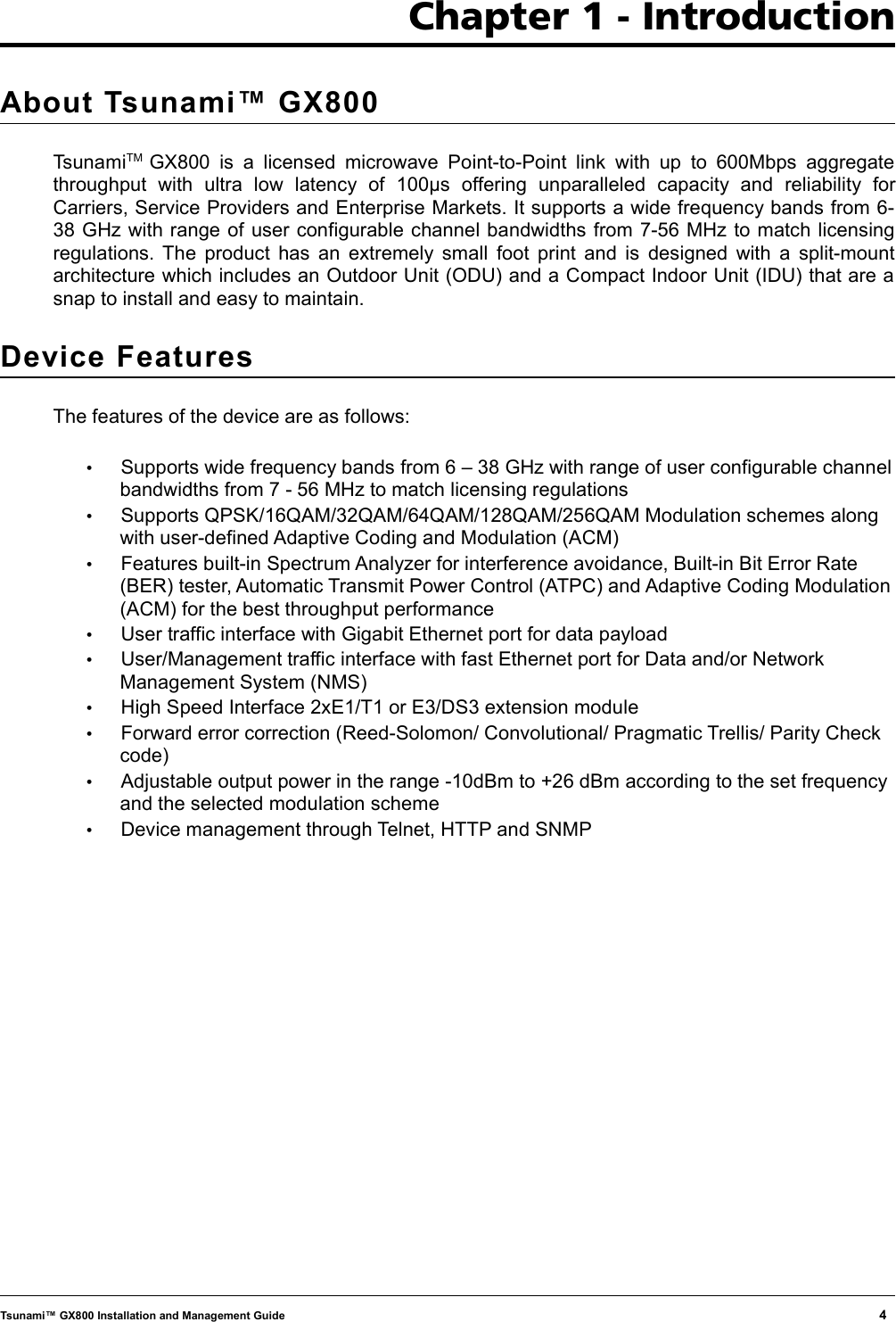
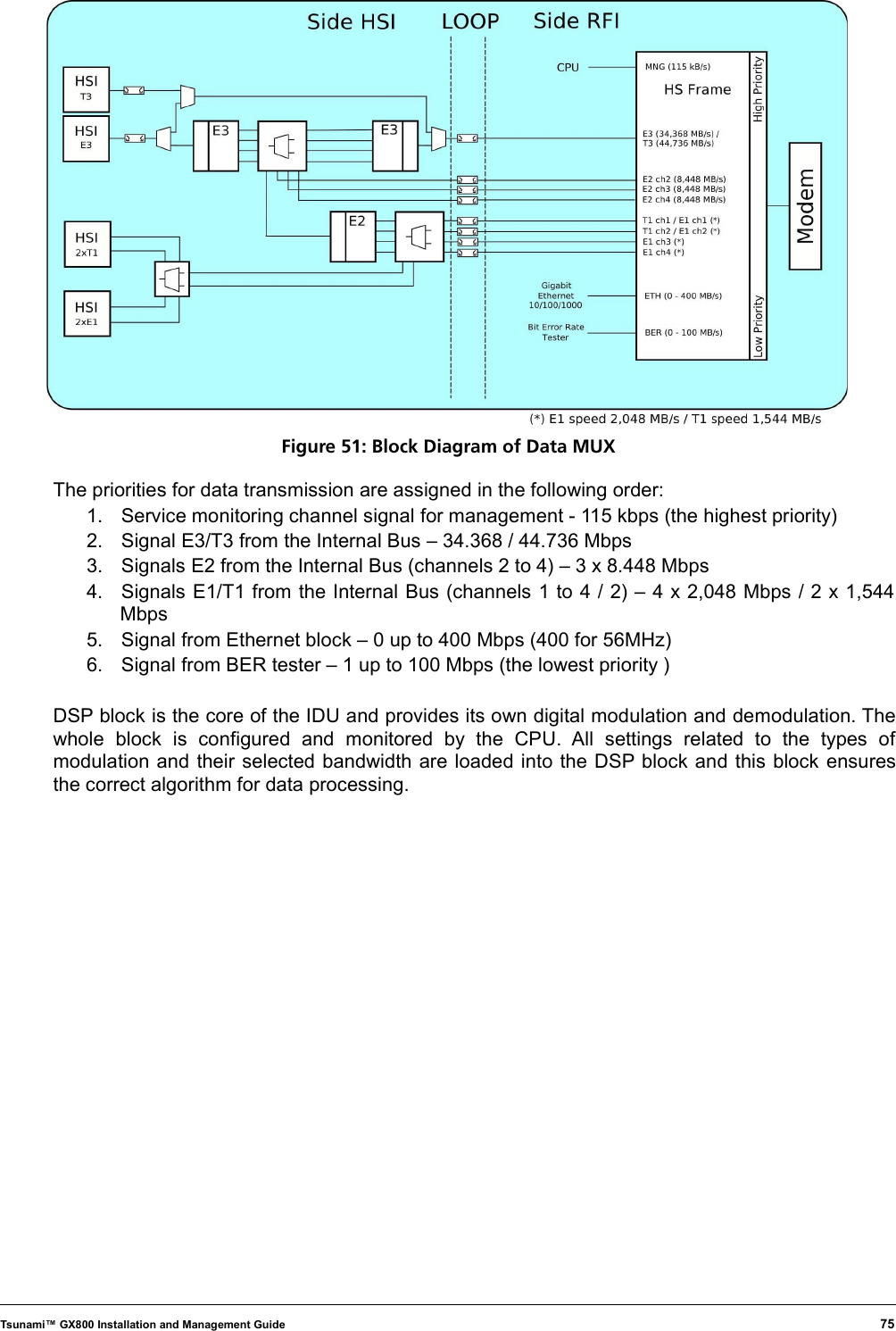
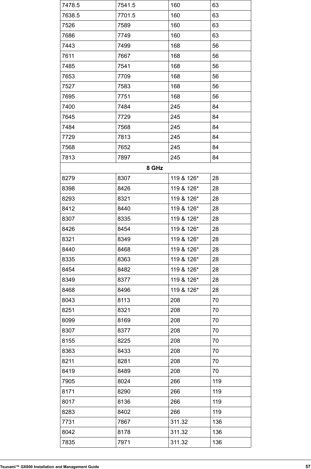
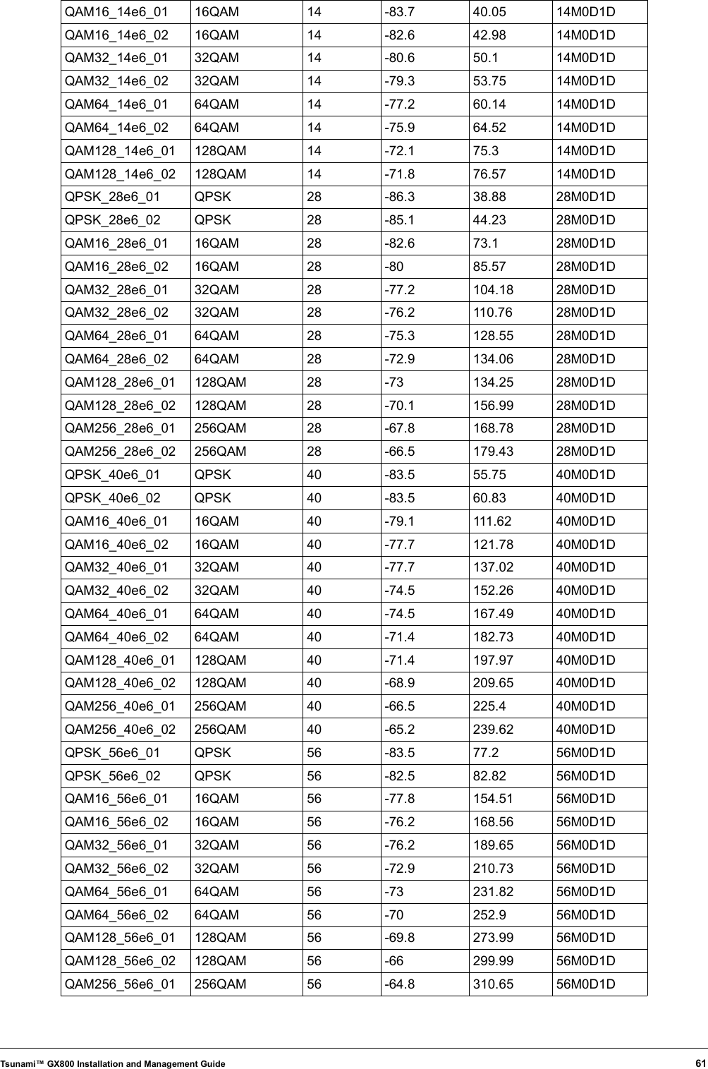
![10/100 Fast Ethernet Port Management/user traffic interface with fast Ethernet port for data and/or Network Management System (NMS)RS232 RJ45 to RS232 Serial port (ASCII console) for local managementUSB A USB memory management portUSB B Craft port. This port is used for production only and not by the end user.HSI MODULE Slot for additional HSI moduleODU N-type Female connector for IDU-ODU connectionPower Supply Power supply connector for -48V DCLED Indicators MSYNC: Sync indicationSTAT1: Local alarmSTAT2: Remote alarmGrounding Screw A provision to ground the IDUFor more information on the IDU functionality, refer to Appendix C - IDU Functionality .Outdoor Unit (ODU)An ODU performs the up-conversion from Intermediate Frequency (IF) of IDU (350MHz) to the desired transmission band, and vice versa; performs the down-conversion from received frequency band to IF frequency (140MHz) for the receiving part of the IDU. Power is supplied to the ODU through the IF cable (used for IDU – ODU connection). The software access to ODU, its management and configuration is possible only from the IDU. ODU management is integrated directly in the command set of the IDU and it is an integral part of the IDU software. For an easy primary set-up of the optimal received signal level, the ODU is fitted with the BNC connector, where the measured DC voltage [mV] is directly proportional to the level of Received Signal Strength (RSSI).Proxim's GX800 ODU is shown below.Tsunami™ GX800 Installation and Management Guide 7Figure 2: ODU](https://usermanual.wiki/Proxim-Wireless/GX800-23/User-Guide-1434452-Page-7.png)

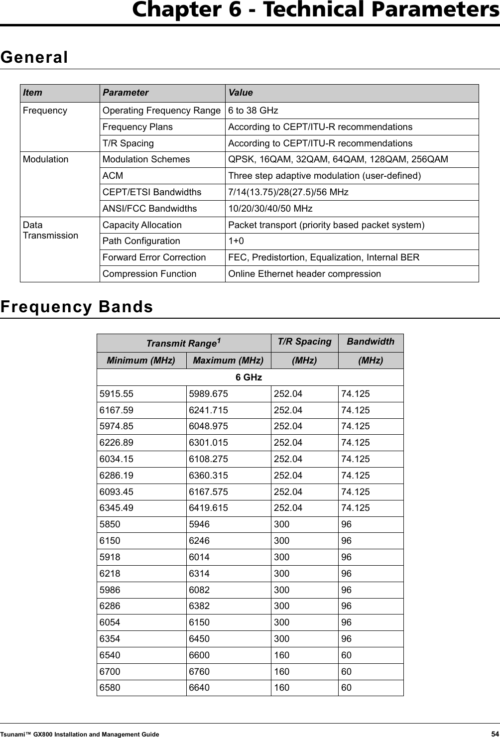
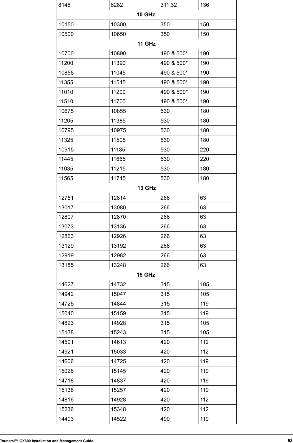
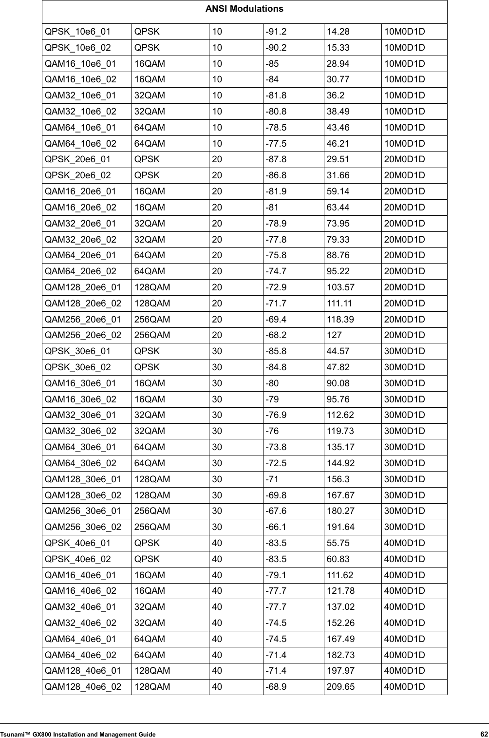
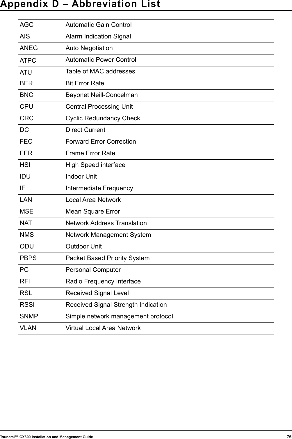
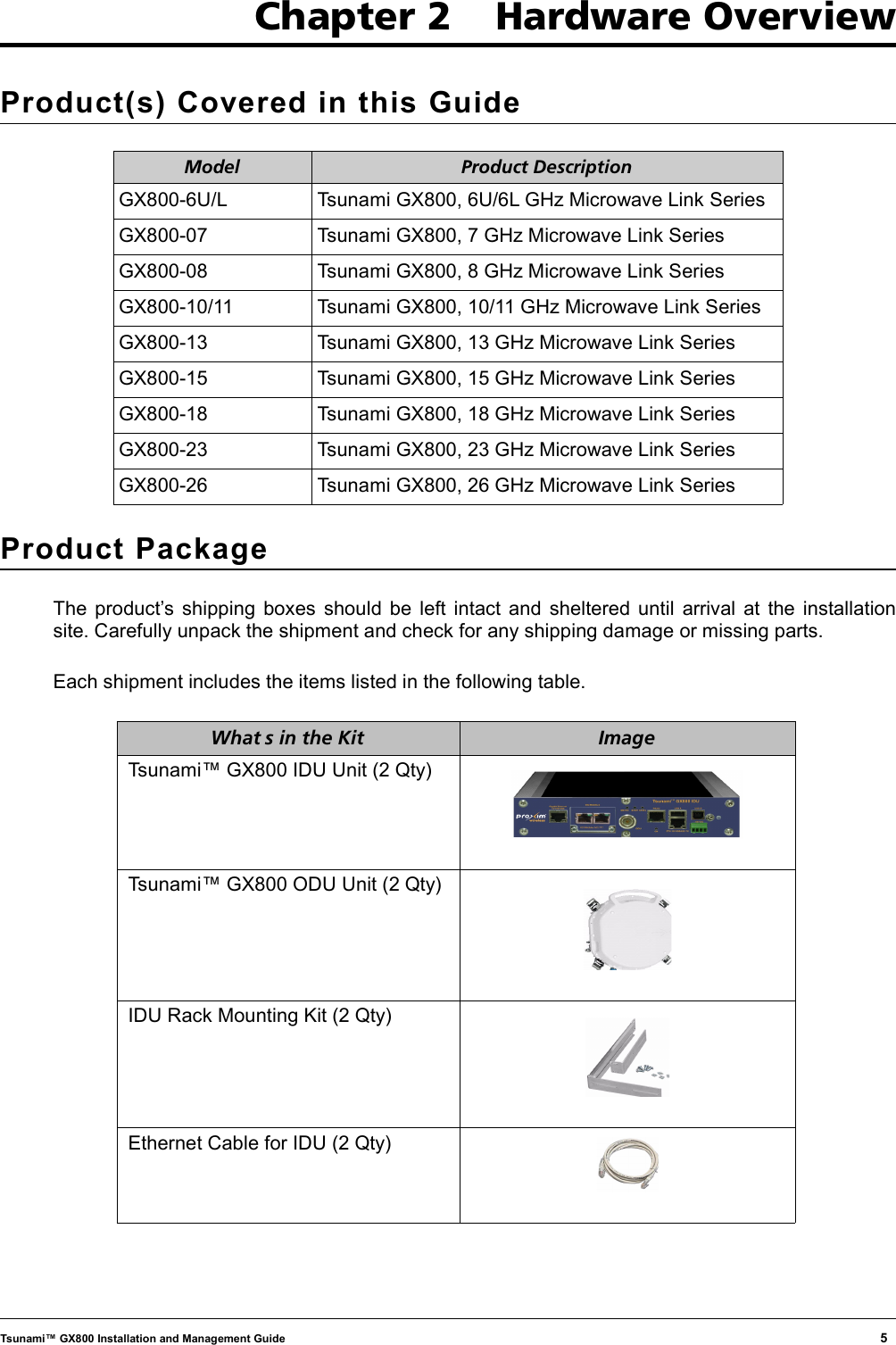
![QAM256_40e6_01 256QAM 40 -66.5 225.4 40M0D1DQAM256_40e6_02 256QAM 40 -65.2 239.62 40M0D1DQPSK_50e6_01 QPSK 50 -83.4 73.7 50M0D1DQPSK_50e6_02 QPSK 50 -82.4 79.07 50M0D1DQAM16_50e6_01 16QAM 50 -77.9 147.51 50M0D1DQAM16_50e6_02 16QAM 50 -76.9 158.25 50M0D1DQAM32_50e6_01 32QAM 50 -74.9 184.42 50M0D1DQAM32_50e6_02 32QAM 50 -73.6 197.84 50M0D1DQAM64_50e6_01 64QAM 50 -71.7 221.32 50M0D1DQAM64_50e6_02 64QAM 50 -70.7 237.43 50M0D1DQAM128_50e6_01 128QAM 50 -68.7 258.23 50M0D1DQAM128_50e6_02 128QAM 50 -67.5 277.02 50M0D1DQAM256_50e6_01 256QAM 50 -65.6 295.13 50M0D1DQAM256_50e6_02 256QAM 50 -64.4 311.24 50M0D1DODU Specification6[GHz] 7[GHz] 8[GHz] 11[GHz] 13[GHz] 15[GHz] 18[GHz] 23[GHz] 26[GHz] TR Space [MHz] / Sub-bands [number] 160/4 154/3 119/6 490/3 266/4 315/3 1010/4 1008/2 800/1 170/4 160/3 126/6 500/3 420/4 1008/4 1200/3 1008/3 252.04/ 4 161/16 208/4 530/4 475/3 1560/3 1232/4 300/4 168/3 266/2 490/4 340/6 196/5 311.32/ 2 640/2 350/6 245/3 644/3 728/1 ODU RF SpecificationItem Parameter Value Polarization Linear per Antenna Vertical or Horizontal Mounting Remote Mount for bands 6, 7, 8 GHz Antenna direct mount for bands 7-38 GHz Transmitter Frequency Stability ± 5 ppm Receiver Frequency Stability ± 5 ppm IDU SpecificationIDU Traffic InterfacesItem Parameter Value 10/100/1000 Gigabit Ethernet Port Number of Ports 1 (RJ45) Basic Function User traffic interface/management VLAN Up to 64 VLANs Tsunami™ GX800 Installation and Management Guide 63](https://usermanual.wiki/Proxim-Wireless/GX800-23/User-Guide-1434452-Page-63.png)
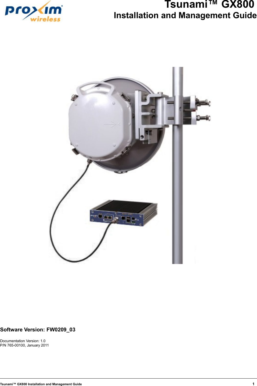
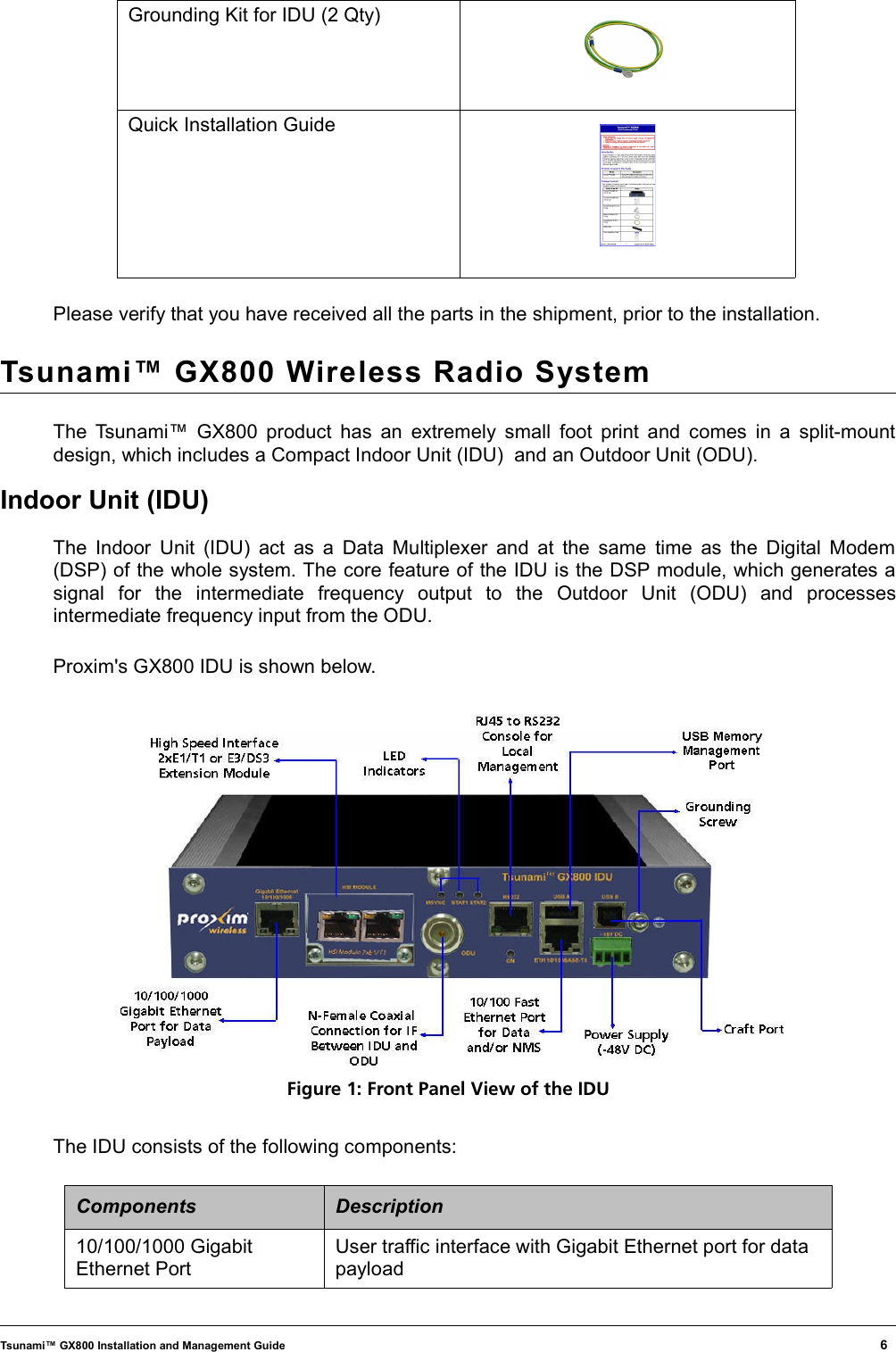
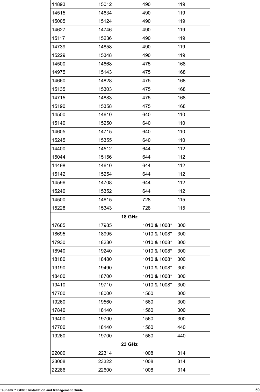
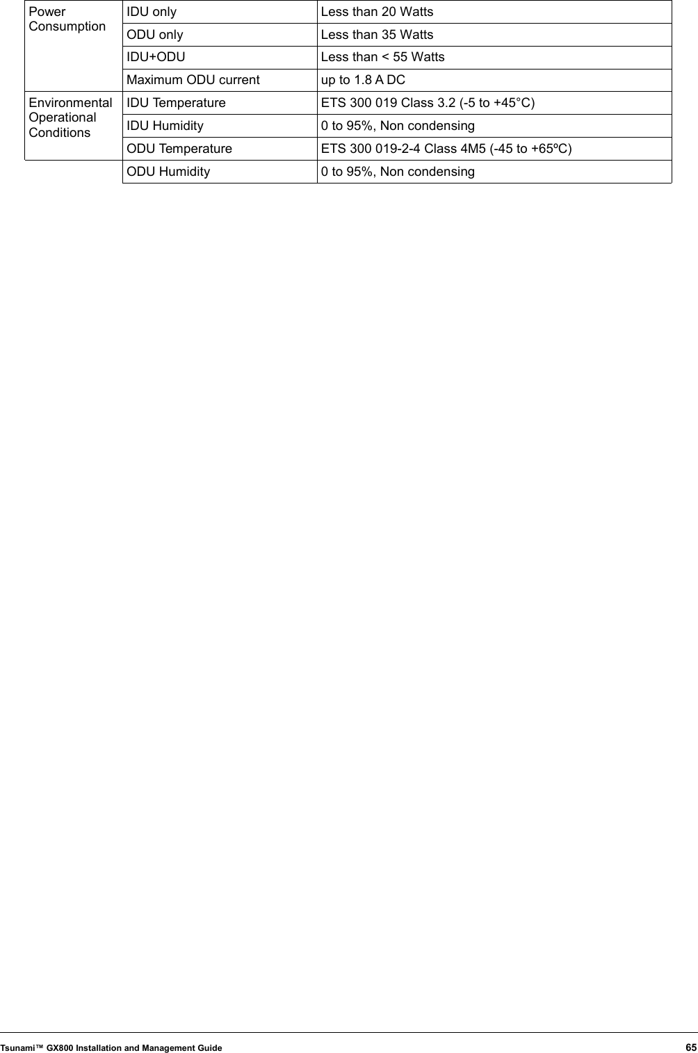
![and10/100 Fast Ethernet Port QoS 802.1p, IPv4 Type of TOS/DiffServ, IPv6 Traffic Class Network ManagementParameter Value Channel In-band and out-of-bandSNMP SNMP v1/v2c, Manageable through ProximVision ES (PVES)Telnet IP Based via dedicated NMS portRS232 Port RJ45 to RS232 Serial port (ASCII console)HTTP Web based GUIUSB USB A - USB Memory Management PortUSB B – Craft PortOut-of-Band Interface 10/100 Fast Ethernet PortWaveguide Interface SpecificationsFrequency Band Circular Waveguide Rectangular Waveguide6 N/A N/A 7 WC112 WR112 8 WC112 WR112 10 N/A WR90 11 WC75 WR75 13 WC75 WR75 15 WC62 WR62 18 WC51 WR42 23 WC42 WR42 26 WC42 WR42!! Note !! The default type is Rectangular but coaxial option for 6GHz is available.MiscellaneousItem Parameter Value IDU Mechanical Dimension [w x h x d] 10.0 x 1.73 x 7.9 inches (Std 19” Half rack mount and 1U height) Weight 2.6lbs ODU Mechanical Dimension [w x h x d] 10.9 x 9.4 x 3.6 inchesWeight Less than or equal to 9.5 lbsInput Voltage Level IDU -20 VDC up to -60 VDC ODU -20 VDC up to -60 VDCTsunami™ GX800 Installation and Management Guide 64](https://usermanual.wiki/Proxim-Wireless/GX800-23/User-Guide-1434452-Page-64.png)
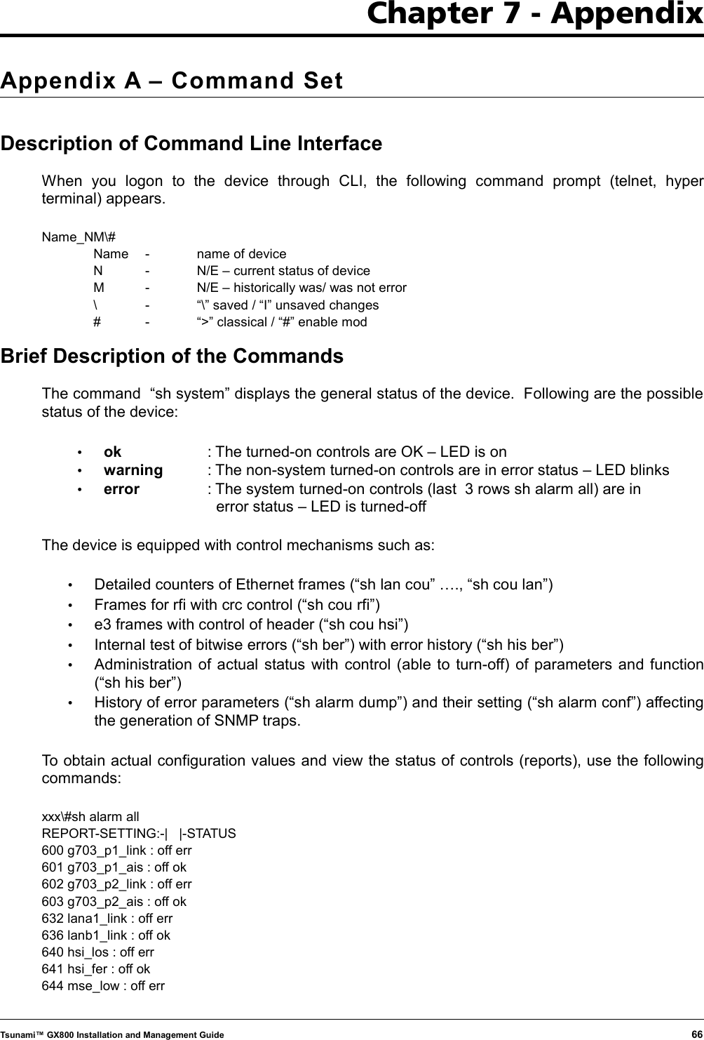


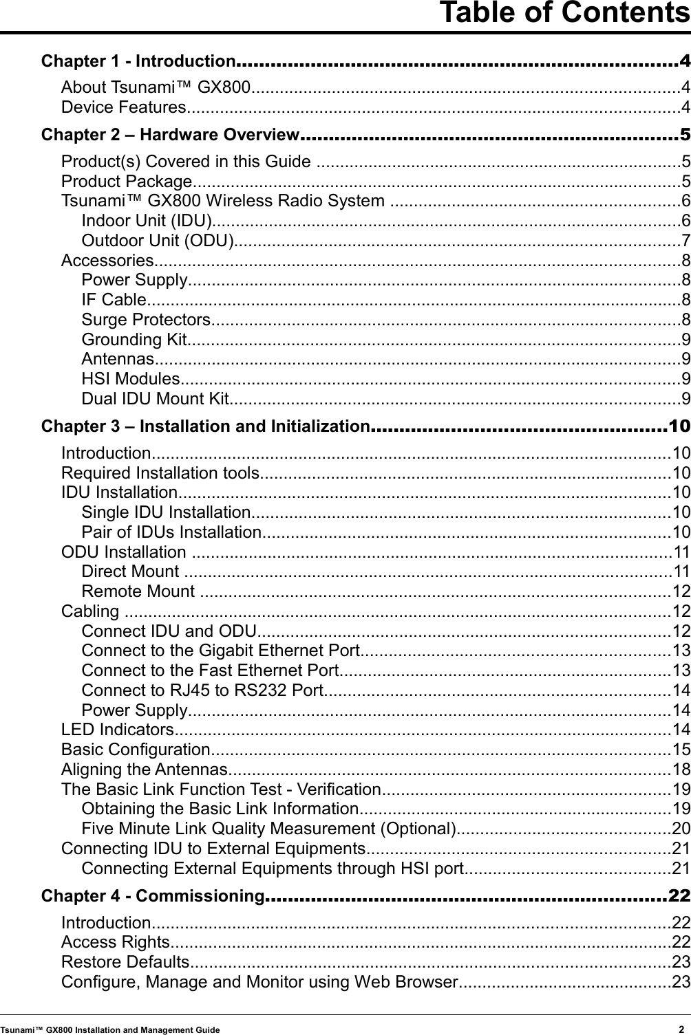
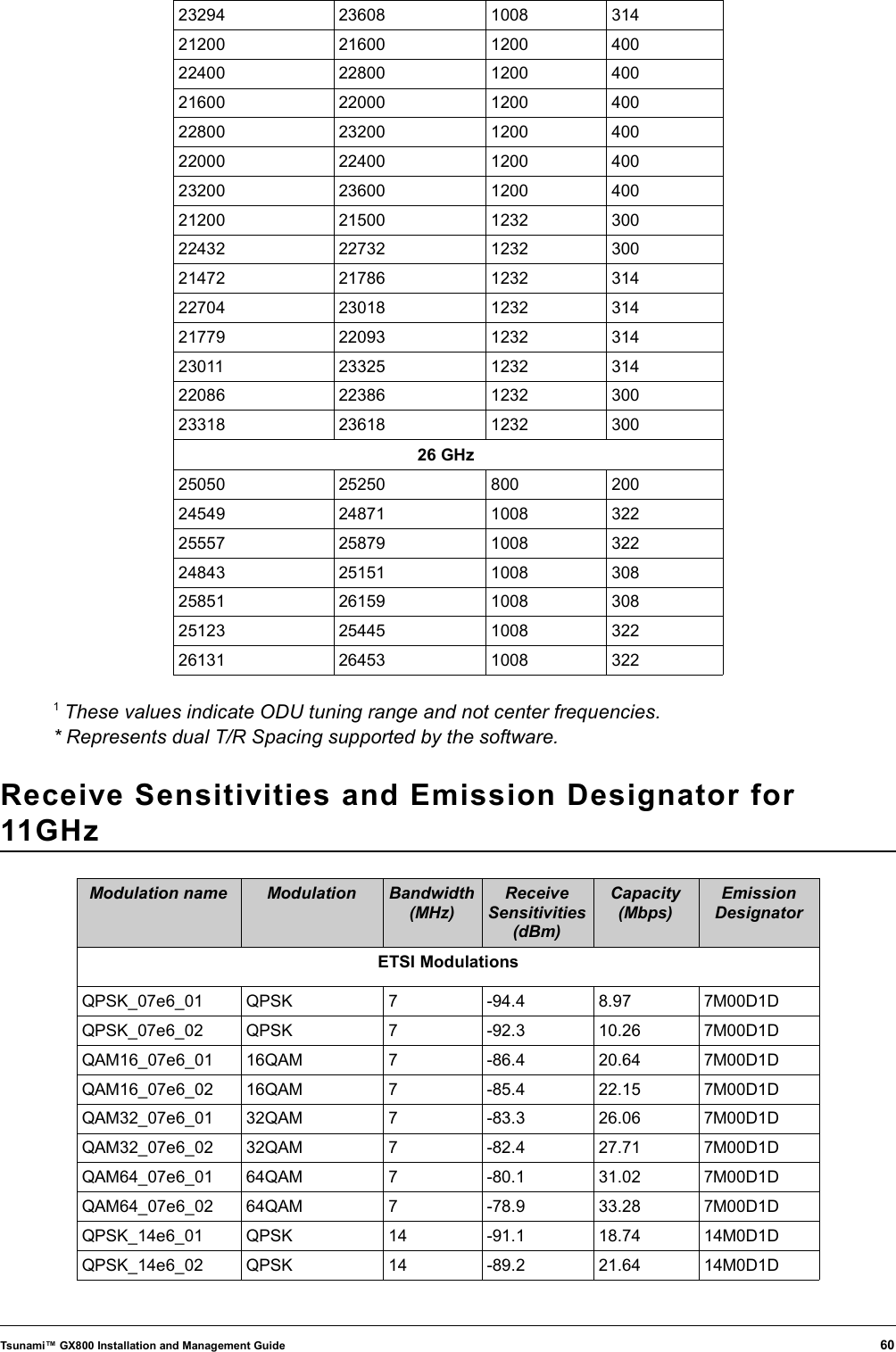
![Appendix B – Using “Help” in Text Terminalxxx\>? - ? : print help... - clear : clear counters (?) - delayed : [x] [cmd] run cmd after x seconds, result in "show hist del" - enable : enable setting - ping : [xx.xx.xx.xx] ping to ip - quit : quit & logout - show : system status & config & counters (?) - telnet : [xx.xx.xx.xx] telnet to ipokxxx\>enableokxxx\#?- ? : print help...- clear : clear counters (?)- delayed : [x] [cmd] run cmd after x seconds, result in "show hist del"- enable : enable setting- exit : exit from enable mode- kill : [xxx] kill user with xxx pid- ping : [xx.xx.xx.xx] ping to ip- quit : quit & logout- reset : resetting device (?)- run : [w0-3/fd/auto/noauto] run config, enable autorun- set : settings (?)- show : system status & config & counters (?)- telnet : [xx.xx.xx.xx] telnet to ip- update : manage files, usb/ftp update (?)- write : [w0-3] write configurationokxxx\#clear ? - atu : clear atu table - ber : clear ber counters - count : clear mux counters - history : clear history logs (?) - lancount : clear lan countersokxxx|#clear history ? - count : clear rfi counter err log - delayed : clear delayed cmd log - alarm : clear alarm log - plog : clear periodical logokTsunami™ GX800 Installation and Management Guide 73](https://usermanual.wiki/Proxim-Wireless/GX800-23/User-Guide-1434452-Page-73.png)