Proxim Wireless GX800-23 Fixed Point-to-point User Manual
Proxim Wireless Corporation Fixed Point-to-point
user manual
Software Version: FW0209_03
Documentation Version: 1.0
P/N 765-00100, January 2011
Tsunami™ GX800 Installation and Management Guide 1
Tsunami™ GX800
Installation and Management Guide

Table of Contents
Chapter 1 - Introduction.............................................................................4
About Tsunami™ GX800..........................................................................................4
Device Features........................................................................................................4
Chapter 2 – Hardware Overview..................................................................5
Product(s) Covered in this Guide .............................................................................5
Product Package.......................................................................................................5
Tsunami™ GX800 Wireless Radio System .............................................................6
Indoor Unit (IDU)...................................................................................................6
Outdoor Unit (ODU)..............................................................................................7
Accessories...............................................................................................................8
Power Supply........................................................................................................8
IF Cable.................................................................................................................8
Surge Protectors...................................................................................................8
Grounding Kit........................................................................................................9
Antennas...............................................................................................................9
HSI Modules.........................................................................................................9
Dual IDU Mount Kit...............................................................................................9
Chapter 3 – Installation and Initialization...................................................10
Introduction.............................................................................................................10
Required Installation tools.......................................................................................10
IDU Installation........................................................................................................10
Single IDU Installation........................................................................................10
Pair of IDUs Installation......................................................................................10
ODU Installation .....................................................................................................11
Direct Mount .......................................................................................................11
Remote Mount ...................................................................................................12
Cabling ...................................................................................................................12
Connect IDU and ODU.......................................................................................12
Connect to the Gigabit Ethernet Port.................................................................13
Connect to the Fast Ethernet Port......................................................................13
Connect to RJ45 to RS232 Port.........................................................................14
Power Supply......................................................................................................14
LED Indicators.........................................................................................................14
Basic Configuration.................................................................................................15
Aligning the Antennas.............................................................................................18
The Basic Link Function Test - Verification.............................................................19
Obtaining the Basic Link Information..................................................................19
Five Minute Link Quality Measurement (Optional).............................................20
Connecting IDU to External Equipments................................................................21
Connecting External Equipments through HSI port...........................................21
Chapter 4 - Commissioning......................................................................22
Introduction.............................................................................................................22
Access Rights..........................................................................................................22
Restore Defaults.....................................................................................................23
Configure, Manage and Monitor using Web Browser.............................................23
Tsunami™ GX800 Installation and Management Guide 2

General Screen.......................................................................................................24
IP Address Setup....................................................................................................25
Interconnection of LAN A-B Ethernet Switches..................................................27
Dual License - Design Type Setup..........................................................................28
Frequency, Modulation and ATPC Setup................................................................28
Ethernet Advanced Configuration...........................................................................32
Data Rate Settings for Connected User Interfaces................................................32
Example 1...........................................................................................................33
Example 2...........................................................................................................33
Save Configured Parameters..................................................................................35
BER Test – GX800 Link and User Lines Verification..............................................36
GX800 BER Test:................................................................................................36
User Line BER Test:...........................................................................................37
Analysis of Interference in GX800 link....................................................................39
Firmware Upgrade, License Upgrade.....................................................................41
Upgrading the License........................................................................................43
Alarms.....................................................................................................................44
SNMP Settings........................................................................................................45
IP Management.......................................................................................................46
In-Band Management through Gigabit Ethernet port.........................................46
Out-of-Band Management through Fast Ethernet Port – Access from one side
............................................................................................................................47
Out-of-Band Management over Fast Ethernet Port – Standard Routing Scheme
(two independent subnets).................................................................................48
In-band and Out-of-band Management – NAT...................................................50
Chapter 5 – Troubleshooting....................................................................52
Chapter 6 - Technical Parameters.............................................................54
General....................................................................................................................54
Frequency Bands....................................................................................................54
Receive Sensitivities and Emission Designator for 11GHz....................................60
ODU Specification...................................................................................................63
IDU Specification.....................................................................................................63
Network Management.............................................................................................64
Waveguide Interface Specifications........................................................................64
Miscellaneous.........................................................................................................64
Chapter 7 - Appendix...............................................................................66
Appendix A – Command Set...................................................................................66
Description of Command Line Interface.............................................................66
Brief Description of the Commands....................................................................66
Appendix B – Using “Help” in Text Terminal...........................................................73
Appendix C - IDU Functionality ..............................................................................74
Appendix D – Abbreviation List...............................................................................76
Tsunami™ GX800 Installation and Management Guide 3

Chapter 1 - Introduction
About Tsunami™ GX800
TsunamiTM GX800 is a licensed microwave Point-to-Point link with up to 600Mbps aggregate
throughput with ultra low latency of 100μs offering unparalleled capacity and reliability for
Carriers, Service Providers and Enterprise Markets. It supports a wide frequency bands from 6-
38 GHz with range of user configurable channel bandwidths from 7-56 MHz to match licensing
regulations. The product has an extremely small foot print and is designed with a split-mount
architecture which includes an Outdoor Unit (ODU) and a Compact Indoor Unit (IDU) that are a
snap to install and easy to maintain.
Device Features
The features of the device are as follows:
•Supports wide frequency bands from 6 – 38 GHz with range of user configurable channel
bandwidths from 7 - 56 MHz to match licensing regulations
•Supports QPSK/16QAM/32QAM/64QAM/128QAM/256QAM Modulation schemes along
with user-defined Adaptive Coding and Modulation (ACM)
•Features built-in Spectrum Analyzer for interference avoidance, Built-in Bit Error Rate
(BER) tester, Automatic Transmit Power Control (ATPC) and Adaptive Coding Modulation
(ACM) for the best throughput performance
•User traffic interface with Gigabit Ethernet port for data payload
•User/Management traffic interface with fast Ethernet port for Data and/or Network
Management System (NMS)
•High Speed Interface 2xE1/T1 or E3/DS3 extension module
•Forward error correction (Reed-Solomon/ Convolutional/ Pragmatic Trellis/ Parity Check
code)
•Adjustable output power in the range -10dBm to +26 dBm according to the set frequency
and the selected modulation scheme
•Device management through Telnet, HTTP and SNMP
Tsunami™ GX800 Installation and Management Guide 4
Chapter 2 Hardware Overview
Product(s) Covered in this Guide
Model Product Description
GX800-6U/L Tsunami GX800, 6U/6L GHz Microwave Link Series
GX800-07 Tsunami GX800, 7 GHz Microwave Link Series
GX800-08 Tsunami GX800, 8 GHz Microwave Link Series
GX800-10/11 Tsunami GX800, 10/11 GHz Microwave Link Series
GX800-13 Tsunami GX800, 13 GHz Microwave Link Series
GX800-15 Tsunami GX800, 15 GHz Microwave Link Series
GX800-18 Tsunami GX800, 18 GHz Microwave Link Series
GX800-23 Tsunami GX800, 23 GHz Microwave Link Series
GX800-26 Tsunami GX800, 26 GHz Microwave Link Series
Product Package
The product’s shipping boxes should be left intact and sheltered until arrival at the installation
site. Carefully unpack the shipment and check for any shipping damage or missing parts.
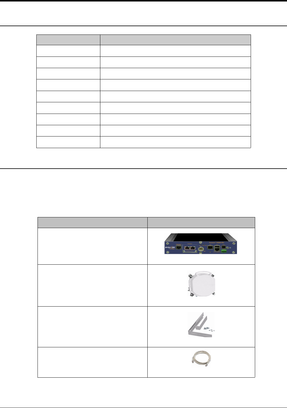
Each shipment includes the items listed in the following table.
Whats in the Kit Image
Tsunami™ GX800 IDU Unit (2 Qty)
Tsunami™ GX800 ODU Unit (2 Qty)
IDU Rack Mounting Kit (2 Qty)
Ethernet Cable for IDU (2 Qty)
Tsunami™ GX800 Installation and Management Guide 5
Grounding Kit for IDU (2 Qty)
Quick Installation Guide
Please verify that you have received all the parts in the shipment, prior to the installation.
Tsunami™ GX800 Wireless Radio System
The Tsunami™ GX800 product has an extremely small foot print and comes in a split-mount
design, which includes a Compact Indoor Unit (IDU) and an Outdoor Unit (ODU).
Indoor Unit (IDU)
The Indoor Unit (IDU) act as a Data Multiplexer and at the same time as the Digital Modem
(DSP) of the whole system. The core feature of the IDU is the DSP module, which generates a
signal for the intermediate frequency output to the Outdoor Unit (ODU) and processes
intermediate frequency input from the ODU.
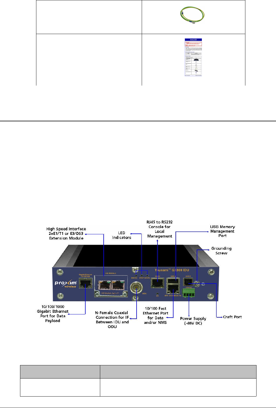
Proxim's GX800 IDU is shown below.
The IDU consists of the following components:
Components Description
10/100/1000 Gigabit
Ethernet Port
User traffic interface with Gigabit Ethernet port for data
payload
Tsunami™ GX800 Installation and Management Guide 6
Figure 1: Front Panel View of the IDU
10/100 Fast Ethernet Port Management/user traffic interface with fast Ethernet
port for data and/or Network Management System
(NMS)
RS232 RJ45 to RS232 Serial port (ASCII console) for local
management
USB A USB memory management port
USB B Craft port. This port is used for production only and not
by the end user.
HSI MODULE Slot for additional HSI module
ODU N-type Female connector for IDU-ODU connection
Power Supply Power supply connector for -48V DC
LED Indicators MSYNC: Sync indication
STAT1: Local alarm
STAT2: Remote alarm
Grounding Screw A provision to ground the IDU
For more information on the IDU functionality, refer to Appendix C - IDU Functionality .
Outdoor Unit (ODU)
An ODU performs the up-conversion from Intermediate Frequency (IF) of IDU (350MHz) to the
desired transmission band, and vice versa; performs the down-conversion from received
frequency band to IF frequency (140MHz) for the receiving part of the IDU. Power is supplied to
the ODU through the IF cable (used for IDU – ODU connection). The software access to ODU, its
management and configuration is possible only from the IDU. ODU management is integrated
directly in the command set of the IDU and it is an integral part of the IDU software. For an easy
primary set-up of the optimal received signal level, the ODU is fitted with the BNC connector,
where the measured DC voltage [mV] is directly proportional to the level of Received Signal
Strength (RSSI).
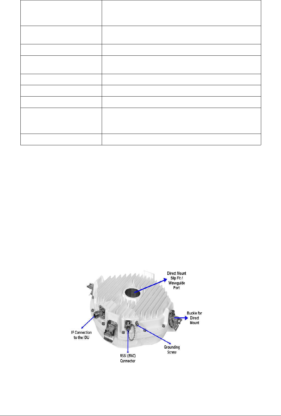
Proxim's GX800 ODU is shown below.
Tsunami™ GX800 Installation and Management Guide 7
Figure 2: ODU

The ODU consists of the following components:
Components Description
IF Connection to the IDU Connector to connect ODU to the IDU
RSSI (BNC) Connector RSSI (BNC) connector to obtain RSSI readings
Grounding Screw A provision to ground the ODU
Direct Mount Slip Fit /
Waveguide Port
Direct Mount: A provision to directly mount the ODU to
the antenna
Remote Mount: Depending on the frequency, a
provision to connect the ODU to the antenna through
Waveguide or Coaxial N-Type SMA Connector.
Buckle for Direct Mount Buckle to secure the ODU onto the antenna interface in
the direct mount.
Due to the tuning limitations of hardware filters within an ODU, different ODU pairs will be
required within any particular frequency band. Given the large amount of spectrum within most
frequency bands, it is required to create smaller ranges as Sub-Bands. ODUs are tunable within
each of the sub-band. It is important to note that ODU pairs are made up with a Hi (High) unit and
a Lo (Low) unit. The Hi unit transmits on the higher channel and receives on the lower, while the
Lo unit transmits on the low channel and receives on the higher.
Accessories
For perfect installation, it is always recommended to use the following parts and accessories. You
can use any other accessories, not approved by the manufacturer or distributor, at your own risk.
Power Supply
The recommended power supply is 120W, regulated switching PS-230/48, power supply with
-48VDC and 2.5A output. From one switching power supply PS-230/48, it is recommended to
power only one side of the GX800 link, that means 1Power Supply x IDU + 1Power Supply x
ODU. When you connect other devices, it may cause power supply overload to the entire GX800
link.
IF Cable
To connect an IDU and an ODU, we recommend you to use low-loss 50 Ohm coaxial cable
designed for outdoor installation. For a distance greater than 50 meters, it is recommended to
ground the cable every 50 meters.
IF Cabling between ODU and IDU must be terminated with N-Male coaxial connections at each
end. Proxim provides 25, 50, 100foot lengths. Custom cables can be made but should be tested
for shorts and overall performance prior to installation.
Surge Protectors
Whenever the coaxial cable enters the building, always install a RF Surge Protector, which
greatly eliminates the risk of high power surge damage.
It is important that the surge protection device permit supply voltage to the ODU. This type of
Tsunami™ GX800 Installation and Management Guide 8

device is known as DC-Passing. It is also important that the IF frequencies of 140MHz and
350MHz be supported by the device. Proxim offers a suitable model in the price list.
Grounding Kit
To ensure good lightning protection for the radio units, install grounding kits on every 50m cable
(each 50 m for long cables) at the building entrance.
We recommend to ground the IDU to the rack cabinet and the ODU to the place, where these
units are mounted such as mast mount, pole and so on. Make special effort to ensure the ground
provides low resistance and avoid ground loops or differentials. Always obey local, state,
provincial regulations with the power and grounding of such systems.
Antennas
A variety of different antennas are available from different manufacturers and in different sizes.
Antennas can be used for horizontal and vertical polarization, the right-sided and left-sided
assembly as well. A list of qualified antennas can be found in the GX800 ordering guide. If
installing into an existing system with a non-direct mount, compatible antenna waveguide
transitions are available. Check with Proxim or your distributor to accommodate this.
Furthermore, regulatory bodies such as ETSI and FCC have strict performance requirements
which must be met by both the antenna vendor and the installer. Always make sure that the
selected antenna meets the regulatory requirements of the locale of installation.
HSI Modules
The IDU comes with a standard 10/100/1000 Gigabit Ethernet RJ45 interface along with a
10/100 Fast Ethernet RJ45 interface for management. For additional traffic interfaces, check with
Proxim for HSI modules. Proxim provides 2xE1/T1 or E3/DS3(G.703) HSI modules.
Dual IDU Mount Kit
The IDUs are designed for standard 19-inch cabinet mounting. Two IDUs can be mounted on a
single rack by using Dual IDU Mount kit.
Tsunami™ GX800 Installation and Management Guide 9
Chapter 3 Installation and Initialization
Introduction
The device must be installed either by a trained professional familiar with radio frequency
planning and the regulatory limits. The equipment must be installed in accordance with the
country national electrical codes.
Required Installation tools
Listed below are the installation tools necessary for installation of the GX800 link. These are not
included in the product package:
•Flat tip Screwdriver
•Cross Screwdriver
•Set of Allen Keys
•Engineer´s Wrench M7, M13, M17
•Vulcanize Isolation Tape
•DC Voltmeter
•BNC Reduction for RSSI Measurement
IDU Installation
The IDU is designed to mount to a standard 19-inch cabinet.
Single IDU Installation
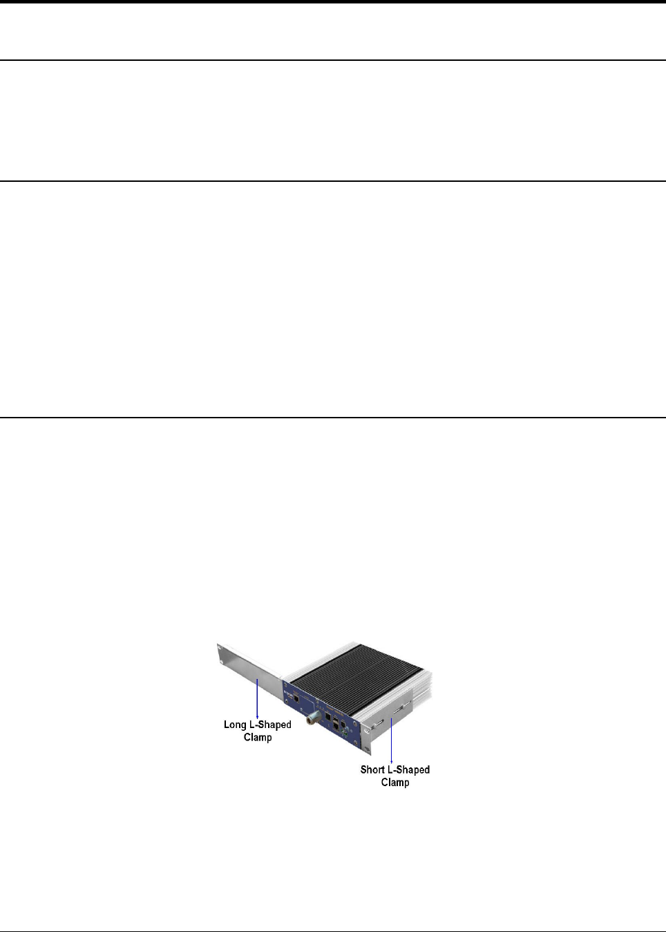
To rack-mount a single IDU, follow the following steps:
1. Fix the small L-shaped clamp (supplied with the product package) to any one side of the
IDU with the provided screws and washers.
2. On the other side of the IDU, fix the big L-shaped clamp (supplied with the product
package) with the provided screws and washers.
3. Next, fix the IDU to the rack.
Pair of IDUs Installation
To rack-mount a pair of IDUs, follow the following steps:
Tsunami™ GX800 Installation and Management Guide 10
Figure 3: Single IDU Mounting
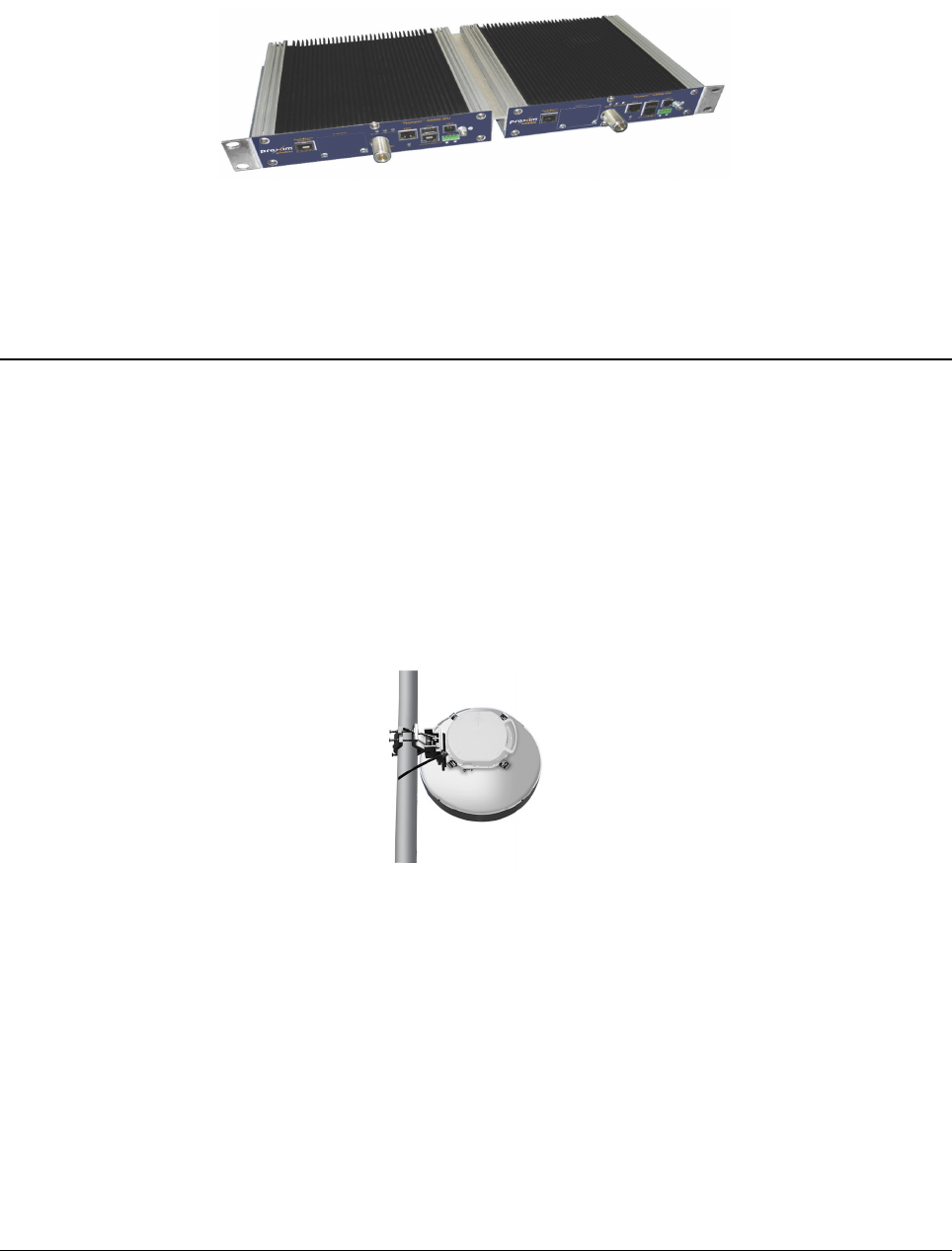
1. Fix the small L-shaped clamps (supplied with the product package) to any one side of the
IDUs with the provided screws and washers.
2. Connect both the IDUs with the Dual IDU Mount kit (not supplied with the product
package)
3. Next, fix the connected IDUs to the rack.
!! CAUTION !! Do not forget to ground the IDU to the rack cabinet with the help of Grounding kit
(supplied with the product package).
ODU Installation
!! Note !! Prior to the installation, carefully remove the cap present on the ODU without
tampering the protective film present inside it.
Direct Mount
In the direct mount, the ODU is fitted to the antenna directly with an ODU interface and secured
using clips.
!! ATTENTION !! Always fasten 2 latches which are adjacent to one another at the same
time.
Setting the Polarization
The polarization depends on the ODU position. An arrow symbol on the ODU identifies the
polarization.
Tsunami™ GX800 Installation and Management Guide 11
Figure 5: Direct ODU Mount
Figure 4: Dual IDUs Mounting
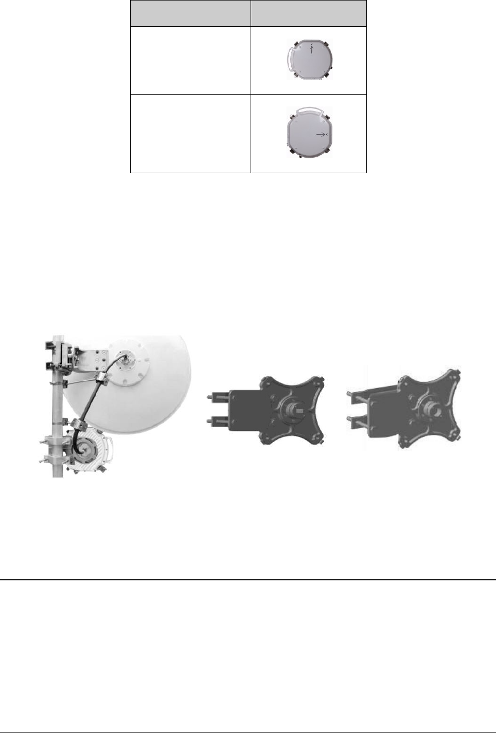
Polarization ODU Position
Vertical Polarization
Horizontal Polarization
!! ATTENTION !! During installation, please ensure that the ODU waveguide slot matches
with the Antenna ODU Interface slot.
Remote Mount
Follow these steps for remote mount:
1. Fix the ODU remote mounting kit (not supplied with the product package) to the pole
2. On the ODU side of the Flange Adapter, fix the ODU.
3. On the flex side of the Flange Adapter, connect one end of the Waveguide. The other end
of the Waveguide is connected to the antenna.
!! NOTE !! Depending on the frequency, the connection between the antenna flange
adapter and the ODU flange adapter should be through a waveguide or coaxial N-type
SMA connector.
Cabling
Connect IDU and ODU
Connect IDU and ODU by using a low-loss coaxial cable (not supplied with the product package)
with the specified impedance of 50 Ohm, terminated on both sides with the N-type Male
connector. Please note that the maximum cable length between the IDU and ODU should be
200m (Additional distances may be permissible but should be verified with Proxim's technical
team).
Tsunami™ GX800 Installation and Management Guide 12
Figure 6: Remote ODU Mounting
!! ATTENTION !!
•Do not plug in ODU while IDU is powered on as this may damage the ODU.
•Before connecting the coaxial cable to the ODU and IDU, please measure the cable
impedance or measure the cable adjustment.
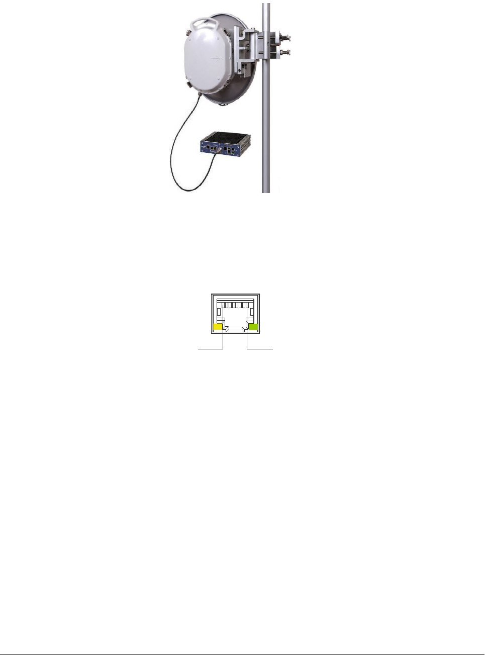
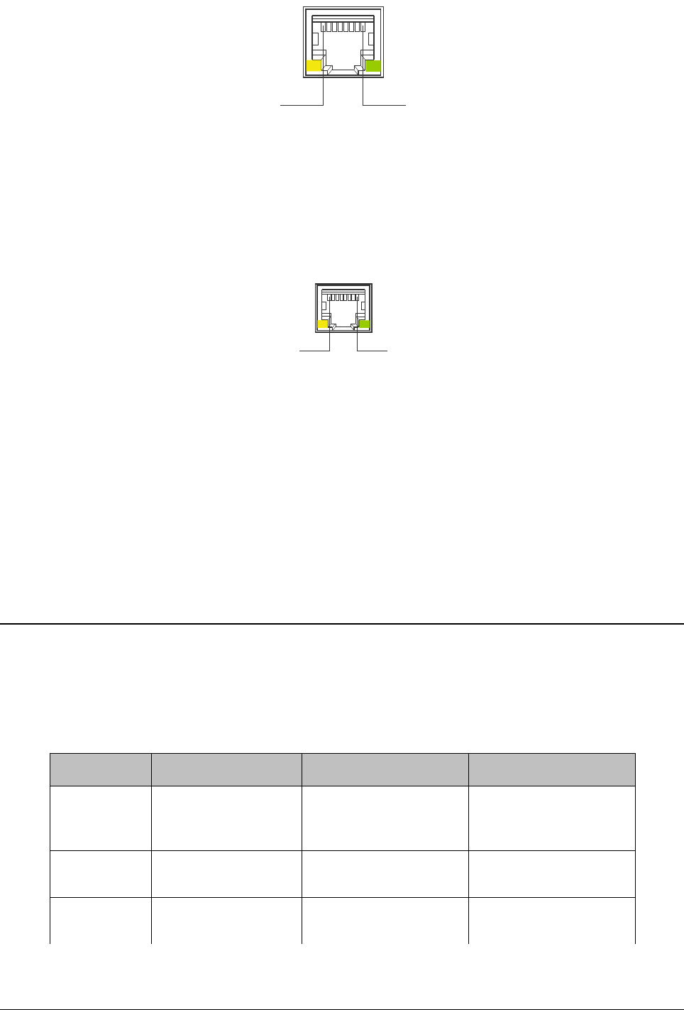
Connect to the Gigabit Ethernet Port
To manage the entire system (link), plug in the Ethernet cable into the 10/100/1000 Gigabit
Ethernet Port of the IDU. The connector wiring is shown below.
!! Note !! Before connecting the Ethernet cable to 10/100/1000 Gigabit Ethernet port, make
sure that the Ethernet cable is not connected to the 10/100 Fast Ethernet Port.
Connect to the Fast Ethernet Port
For primary configuration and to manage the entire system (link), plug in the Ethernet cable into
the 10/100 Fast Ethernet Port of the IDU. The connector wiring is shown below.
Tsunami™ GX800 Installation and Management Guide 13
Figure 7: IDU - ODU Cabling
Figure 8: Pin Assignments for Gigabit Ethernet Port
Pin 1 - DA+, Pin 2 - DA-
Pin 3 - DB+, Pin 6 - DB-
Pin 4 - DC+, Pin 5 - DC-
Pin 6 - DD+, Pin 7 DD-
8
1
Connect to RJ45 to RS232 Port
For local management, plug in the console cable into RJ45 to RS232 port. The connector wiring
is shown below.
Power Supply
The device is powered from a DC source (-48V DC) where the positive pole is grounded. By
using adequately gauged cable, properly ground the ODU to the best earth ground available.
Similarly, properly ground the IDU to the cabinet.
LED Indicators
When the device is powered on, it performs startup diagnostics. It is necessary to wait for about
30 seconds before the IDU gets into normal operating state after powering up. When the device
starts up, watch the status diodes MSYNC, STAT1, STAT2. You should see only the diode
STAT1 flashing after the device starts up (if the alarms are not configured, the LED may remain
lit permanently).
LED State MSYNC LED STAT1 LED STAT2 LED
OFF No Power or Loss
of Synchronization
Local IDU Status -
ERROR
Remote IDU Status –
ERROR or No
Communication
Continuous
Blinking
Boot Process Local IDU Status –
WARNING
Remote IDU Status –
WARNING
ON Sync of Modulation Local IDU Status –
OK
Remote IDU Status–
OK
You can proceed with the initial link configuration and antenna alignment when the IDU starts up.
Tsunami™ GX800 Installation and Management Guide 14
Figure 10: Pin Assignments for RJ45 to RS232 Connector
Pin 3 RxD (PC input)
Pin 6 TxD (PC output)
Pin 1 - CTS, Pin 8 RTS (internally connected)
Pin 2 - DTR, Pin 7 DSR (internally connected)
Pin 5, 6 GND
8
1
Figure 9: Pin Assignments for 10/100 Fast Ethernet Port
Pin 1 - TX+, Pin 2 - TX-
Pin 3 - RX+, Pin 6 RX-
81
Basic Configuration
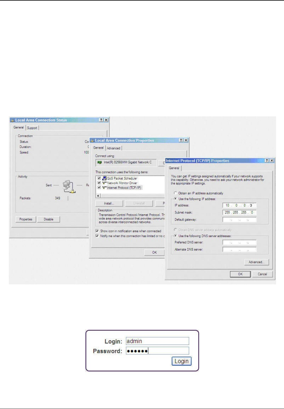
For the initial configuration, use a Personal Computer (PC) with an Ethernet interface, and
current Web Browser (Mozilla, Internet Explorer, Chrome and so on). The operator should have
administrative rights on the PC, with the ability to change the adapters IP address and other
interface settings.
Follow the following steps to perform basic configuration of the device:
1. First set your computer's IP address to the range which corresponds to the default IDU
factory setup. Each IDU unit has the pre-set primary IP address 10.0.0.1 for A-side or
10.0.0.2 for B-side with the network mask 255.255.255.0. Therefore it is necessary to set
the IP address of your computer in the same range of 10.0.0.3 - 254, except for the
device IP address. Configure your computer's IP address (For example 10.0.0.3) and
subnet to 255.255.255.0.
2. The Login screen appears. Open a web browser and log on to the device by entering
http://10.0.0.1 for A-side and http://10.0.0.2 for B-Side in the address bar. The Login
screen appears.
3. In the Login Screen, enter the User Name and Password and then click Login. For user
Tsunami™ GX800 Installation and Management Guide 15
Figure 12: Login Screen
Figure 11: Configure PCs IP Address
modes and their passwords refer to Access Rights. Upon successful logon, you are
directed to the device home page.
4. Navigate to the IP tab and change the Primary IP address. When complete, click Apply.
Tsunami™ GX800 Installation and Management Guide 16
Figure 13: Home Screen
Figure 14: Change IP Address
5. You are now prompted to Write and Reload the device. Click Write_and_Reload for the
IP change to take effect.
6. Log back into the device by using either the Primary or Secondary IP address.
7. Navigate to the Radio tab and perform the following:
•Under ODU Configuration, verify if Tx and Rx center frequencies match your
license.
•Under Modem Configuration, select the Modulation and Channel Bandwidth in
accordance with the link design and licensed operation.
•If you are using Adaptive Modulation, check the Enable ACM box and
select the appropriate High, Mid, Low modulation settings.
•Click Apply.
8. When you complete all the settings, click COMMIT on the upper right corner of the
Tsunami™ GX800 Installation and Management Guide 17
Figure 15: Save IP Configuration
Figure 16: Radio Settings
screen. To logout, click LOGOUT and repeat the same steps on the remote side of the
link.
!! ATTENTION !! Do not forget to save the configured parameters by performing a
“COMMIT” operation.
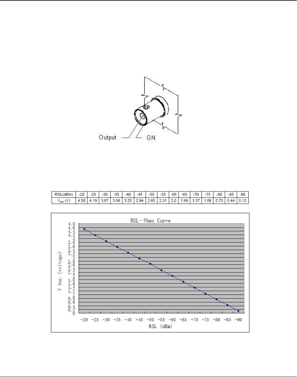
Aligning the Antennas
Align the antenna (not supplied) only when both the terminals are operating in normal weather
conditions.
Antenna alignment can be done in both horizontal and vertical directions by using a DC
voltmeter. The higher the measured voltage is, the highest is the received signal level. The
voltage is measured directly on the output BNC connector on the ODU (RSSI - Received Signal
Strength Indication). It is recommended to use an appropriate BNC adapter for your DVM.
Given below is the typical Receive Signal Level Voltage for licensed bands.
Antenna alignment should be done only during favorable weather conditions. During adverse
weather conditions such as rain, fog, snow and smog, antenna alignment should not be done as
Tsunami™ GX800 Installation and Management Guide 18
Figure 18: RSL Vbnc Curve
Figure 17: RSSI Connector

the value of the measured signal varies significantly, and so the measurement risks becomes
inaccurate.
!! ATTENTION !! When aligning the antennas watch out for the possibility of "false"
alignment on the side lobes of remote antenna. It is important to identify main lobe
antenna, by rotating the antenna to have the maximum RSL voltage. The value of RSL
should always correspond to expected calculated value of input signal strength.
The Basic Link Function Test - Verification
Before connecting to the user's ports, it is good to quickly perform a basic test that verifies proper
GX800 link installation and its error-free condition.
Obtaining the Basic Link Information
To obtain basic link information, navigate to General menu and Status sub-menu in the
Graphical User Interface (GUI) and evaluate the following parameters:
Key Parameters Description
TX Power Data should have a value corresponding to the assignment
(Telecommunication Authority)
RX Level Data should be in the range -35 to -50 dBm and should correspond
to the expected level resulted from calculation tolerance + / - 3dBm).
Approximately the same value (+ / - 3dBm) should be measured on
the opposite side too.
Mean Square
Error (MSE)
Data should be in the range -40 (better) to -32(worse) dB (the lower
the better)
The Mean Square Error (MSE) refers to the average of the square
difference between the actual received symbols and the idealized
points. The closer the points are in the state diagram - the better.
Modem sync The synchronization status of the modem part should be set to OK.
MSE threshold for each modulation is as follows:
128QAM : - 26 dB
64QAM : - 23 dB
32QAM : - 20 dB
16QAM : - 17 dB
QPSK : - 10.5 dB
The same evaluation needs to be done on the other side of the link.
!! Note !! As final adjustment of the GX800 link parameters is not yet done (especially IP
address), you may find the icon of the opposite terminal not yet glowing green.
If the measured values do not match the above said values, it is necessary to perform a detailed
check of the link adjustment.
Tsunami™ GX800 Installation and Management Guide 19
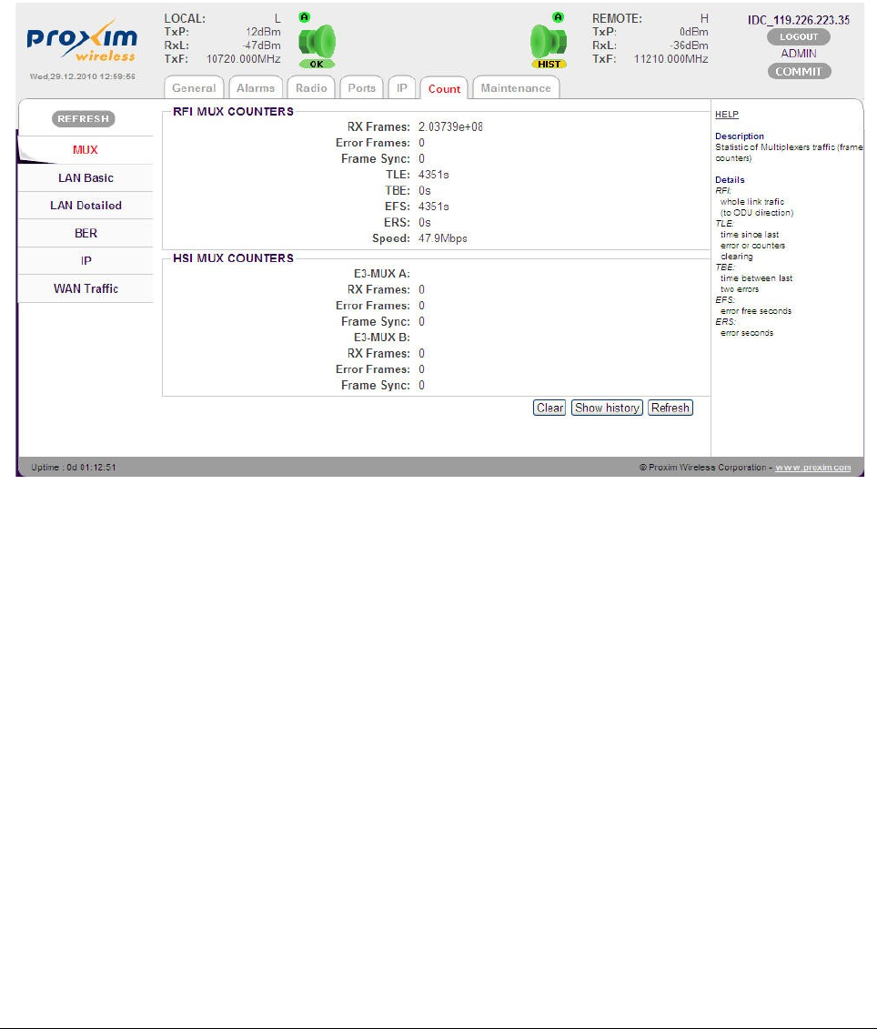
Five Minute Link Quality Measurement (Optional)
The next step is a five minute BER measurement test of the link. Note that to perform this test,
data interface connection is not required.
To perform this test, do the following:
1. Click Clear in the General tab to clear all counters and validate all alarms on local and
remote side of the link.
2. Wait for 5 minutes and then navigate to Count tab and select sub-menu MUX.
The results should be:
•RF Frames - The number of correctly received frames
•Error Frames - The number of error frames; it value should be 0
•TLE - Time in seconds since last error occurred; it should be same as EFS.
•EFS - Error free seconds; it should be same as TLE.
•ERS - Error seconds; time in seconds during which the errors occurred. The value
should be “0”.
Similar results should be seen on the opposite side of the link as well.
If test results vary, you have to perform a detailed check of the link installation and configuration.
Tsunami™ GX800 Installation and Management Guide 20
Figure 19: MUX Statistics
Connecting IDU to External Equipments
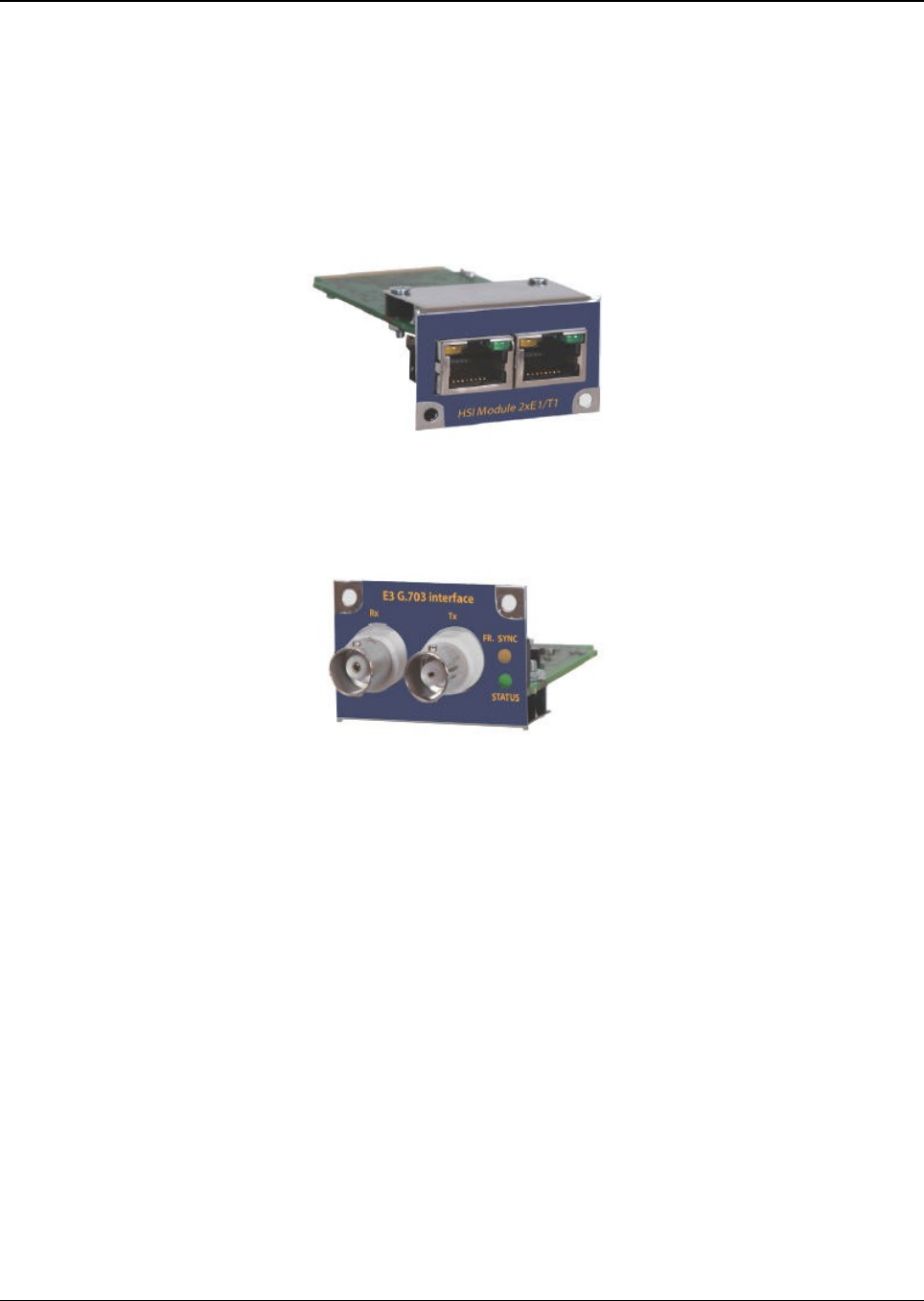
Connecting External Equipments through HSI port
Depending on the configuration (customer´s order) the IDU is equipped with specific HSI module.
To extend the functionality of GX800 system with 1-2 E1/T1 ports, use IDU configuration with
inserted HSI-2E1/T1 module. You can directly connect to a maximum of two E1/T1 lines or
devices through RJ48 connector.
To extend the functionality of GX800 system with 1 E3/DS3 (G.703) ports, use IDU configuration
with inserted HSI-E3/DS3 module.
Tsunami™ GX800 Installation and Management Guide 21
Figure 20: HSI 2xE1/T1 Module
Figure 21: HSI E3/DS3 Module

Chapter 4 - Commissioning
Introduction
After the installation of the link, it is necessary to carry out the complete setup of all the required
link parameters including IP management. It is recommended to save the parameters such as IP
addresses, Tx Frequency, Tx Power as these parameters can be restored easily in case of the
device replacement.
This section covers the method to set up GX800 link by using Web Interface. The link setup by
using text commands is covered in Appendix A – Command Set.
Access Rights
Log on to the GX800 link system, either locally or remotely to mange and monitor the link. Based
on the type of user logged in, relevant access rights are automatically granted to the user. These
access rights are applicable both in web and command line interfaces.
GX800 supports three levels of login modes.
Guest
A Guest user can,
•Monitor the traffic on the GX800 link, the Quality of the frequency tuning and the
configured parameters of the link (Tx Power and so on)
•Clear BER tester and so on
The link system supports a maximum of three guest user logins at the same time. The login
name is guest. Please note that a Guest can login without a password.
User
A User has the same access rights as the Guest user, with additional rights to configure and set
the GX800 link parameters. The link system supports only one User login at the same time. With
User logged in, a maximum of three Guest users can login to monitor the device.
The login name is user and password is test.
Administrator
An Administrator has the same rights as that of the Guest and User, with additional rights to
upload a new firmware, control user's database, and change the user name and password.
Administrator user posses the superior level of user access and management of the link. When
the administrator user logs in, all the other users are logged out automatically.
The login name is admin and password is secret.
Tsunami™ GX800 Installation and Management Guide 22
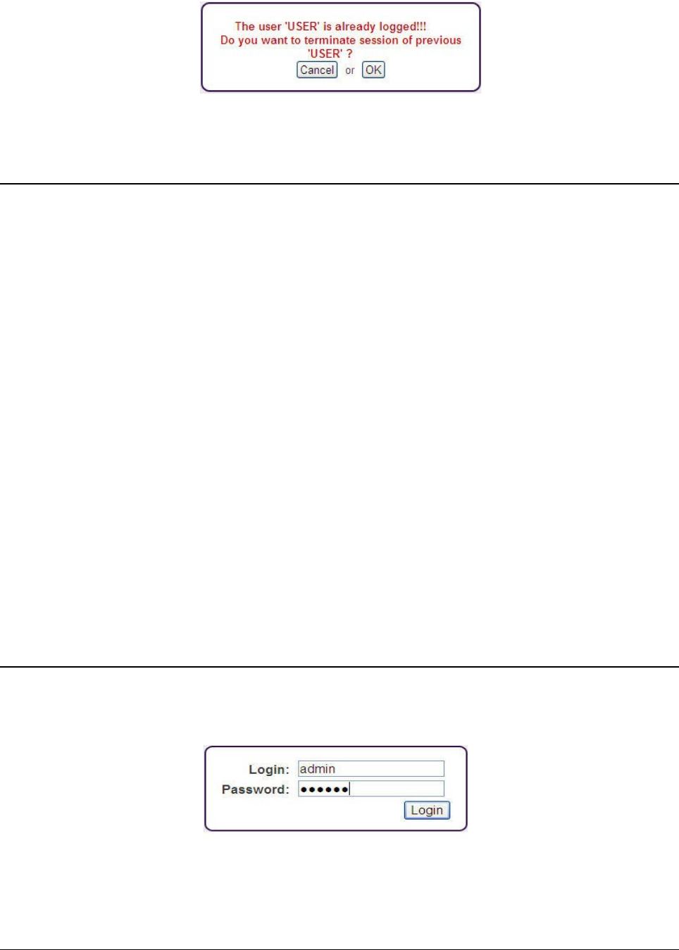
The following alert message is displayed, when a user is already logged in and an Administrator
tries to login.
Restore Defaults
To restore the default access names and passwords (admin/secret, user/test, guest/-) including
the secondary IP address, follow any one of the below methods:
•Restore using RS232 Console:
•Establish a serial connection
•Enter Login name as default
•Enter Password as restore. Please note that password should be written within
two minutes of providing the user name.
•On providing the correct user name and password, the user is immediately
disconnected and passwords along with the IP address are restored.
•Restore using USB Flash:
•Check the SN number of the IDU
•Copy the rfwATH.afw file (or appropriate file) on USB disk into directory
“/restoreFW” and rename this file to “rfwSN.afw”, where the SN is the serial
number of the IDU.
•Turn off the IDU
•Turn on the IDU
•Wait for the LED to blink during the boot process
•Insert USB disk into port USB A
•Wait for 1 minute until the process termination (the indication LED on USB disk
should blink during this process)
Configure, Manage and Monitor using Web Browser
Open a web browser and log on to the device by entering http://10.0.0.1 for A-side and
http://10.0.0.2 for B-Side in the address bar. The Login screen appears.
The login section is active until the logout. It is not possible to configure the IDU from two
terminals at the same time (only one terminal can be active in the setup (enable) mode), that is
the user with access rights User or Administrator.
Tsunami™ GX800 Installation and Management Guide 23
Figure 23: Login Screen
Figure 22: Admin Login – Alert Window
The device has an automatic time-out option, which automatically logs out a user if no
configuration/operation is performed in the past 10 minutes. A “User” can logout another logged
in “User” but not an “Admin”. However, an “Admin” can logout any user.
!! ATTENTION !! During the setup or to view the previous screens, do not use the browser
functions “back“ and “refresh“! Use only the tabbed menu of the device, always with a
single click for a particular operation.
In the Login Screen, enter the User Name and Password, and then click Login.
For a Guest user, the login name is guest and password is blank.
For a User, the login name is user and password is test.
For an Admin user, the login name is admin and password is secret.
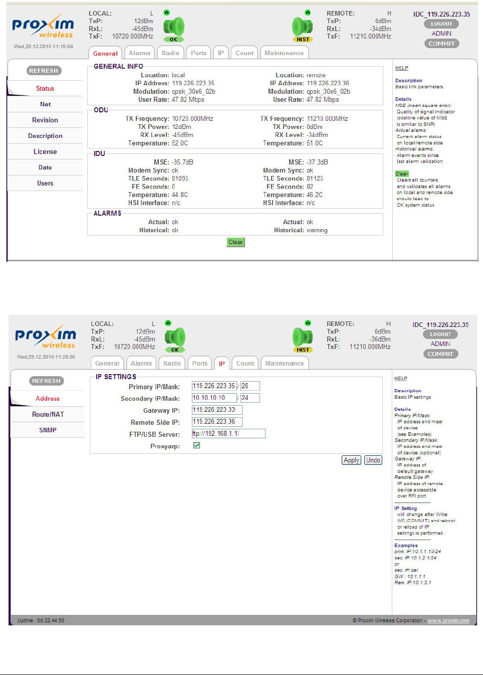
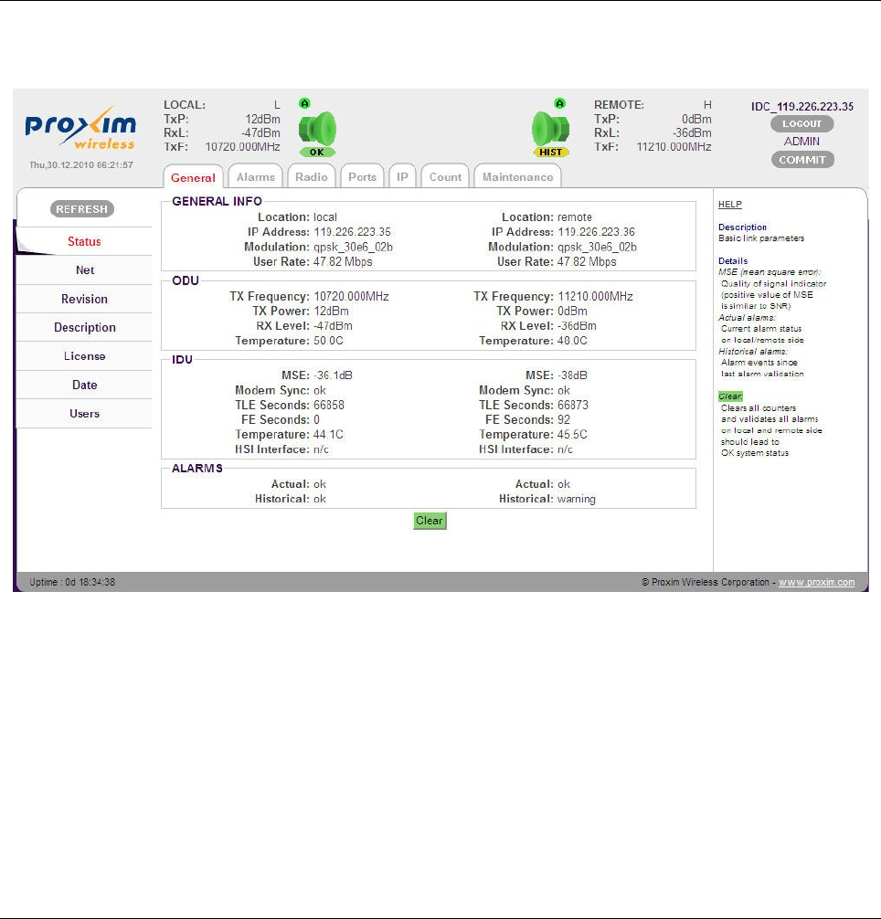
General Screen
Upon successful logon, you are directed to the device General screen.
The General page enables you to check the status of GX800 link. This screen contains
information about the local as well as remote link, provided the remote side IP parameters are
properly set on both terminals.
It displays:
•Current running modulation scheme
•Data Bit Rate (the net throughput in the range from 10 up to 310Mbps)
•TX frequency and output TX Power, the Temperatures of IDU and ODU
•Mean Square Error (MSE) - An absolute value proportional to the quality of signal at
demodulation, that is, the lower the value the better is the signal. This parameter is
Tsunami™ GX800 Installation and Management Guide 24
Figure 24: General Screen

usually in the range of -12dB to -40dB.
•For QPSK modulation, the limit value is -10.5dB; for QAM128 modulation, the limit value
is -26dB. (Well designed and installed link has usually MSE value of -32dB and lower, so
the link runs without the errors in QAM 128 modulation). Note that MSE parameter might
display unpredictable values, if Modem sync is not set to OK status,.)
•Modem sync - Modem synchronization (ok = correct; no = no synchronization)
•HSI Interface - The type of connected HSI module to the IDU
•Actual – The status of the overall link (ok=correct)
•Historical – The status from the last alarm acknowledgement (ok = correct; warning =
there was an error in the past)
On the top of every screen, you can read the following:
•Color-coded radio icons together with colored flags and off-hand distinguished status of
the local and remote link terminal.
1. Indication of the Radio Icon: Green – OK; Red - error; Grey - inaccessible
remote device; Yellow - warning status
2. Flag A: “not-crossed A” – enabled auto restore configuration from start-up
memory W0 after continuous 10 minutes error timeout (applicable if connection
is lost)
3. Flag Status (flag below radio icon): Green – OK; Yellow – WARN (an error
occurred now); Yellow – HIST (information about previous error, the device is
OK now); Grey – N/A (flag on local side – no communication between IDU and
ODU on local side); Grey – N/A (flag on remote side – no communication
between local and remote device)
4. BAND: Indicates the low/high frequency on the local and remote side of the link
5. TxP: Transmit power
6. RxL: Received level (preferably in the range of -30dBm to -50dBm)
7. TxF: Transmitting frequency set in the allowed frequency range of each unit
8. COMMIT: Stores configured parameters to the permanent startup memory
IP Address Setup
Each IDU in the network must have its own unique IP address, defined subnet mask and the
primary route (gateway). For the link to function correctly (display of the remote device status) it
is also important to set the address of the remote device.
To setup the IP address, navigate to the main menu “IP” and the sub menu “Address”.
Tsunami™ GX800 Installation and Management Guide 25
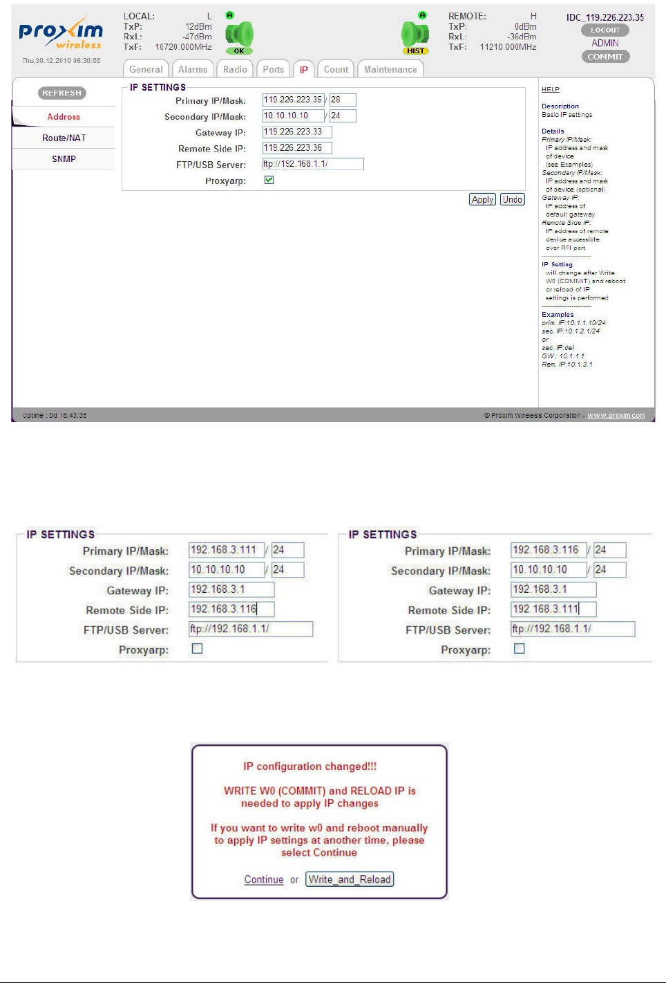
For example, a device in the network has IP 192.168.3.0/24, gateway 192.168.3.1. The
management data can be transmitted together with the user data through the common cable
connected from the same switch into single Gigabit Ethernet port (port for user data).
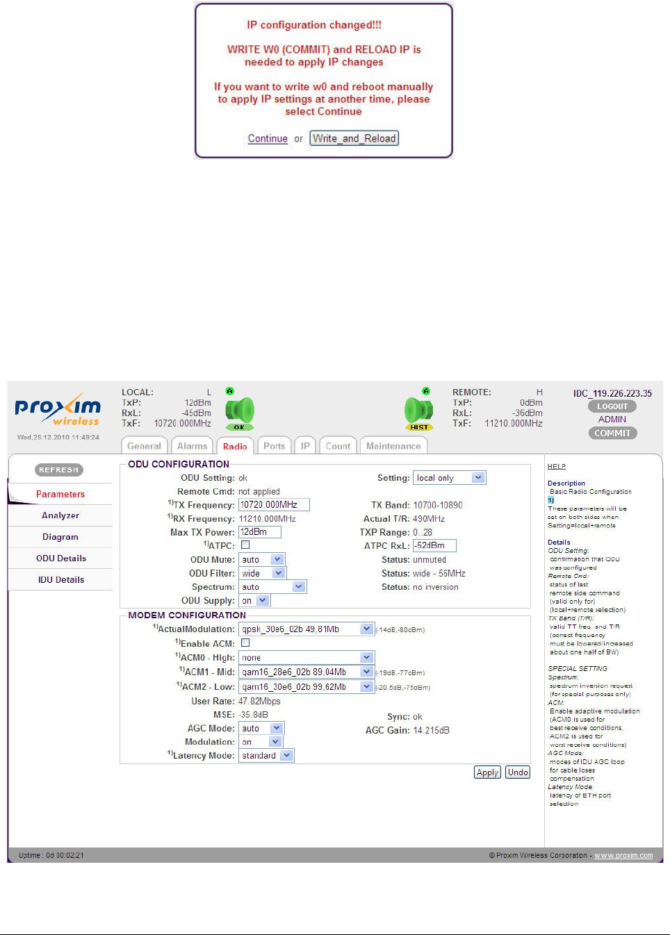
After configuring the IP settings, click Apply. The following alert screen appears:
Tsunami™ GX800 Installation and Management Guide 26
Figure 25: IP Address
Figure 27: IP Configuration Change Window
Figure 26: IP setup for device A (left) and device B (right)
Click Write_and_Reload to save the new configuration parameters onto Write_W0 startup
memory.
!! NOTE !! Proxyarp feature is accessible in ADMIN mode only.
!! ATTENTION !! Any change or modification in the IP setting takes effect only after saving
the configuration to “Write_W0” memory followed by device restart.
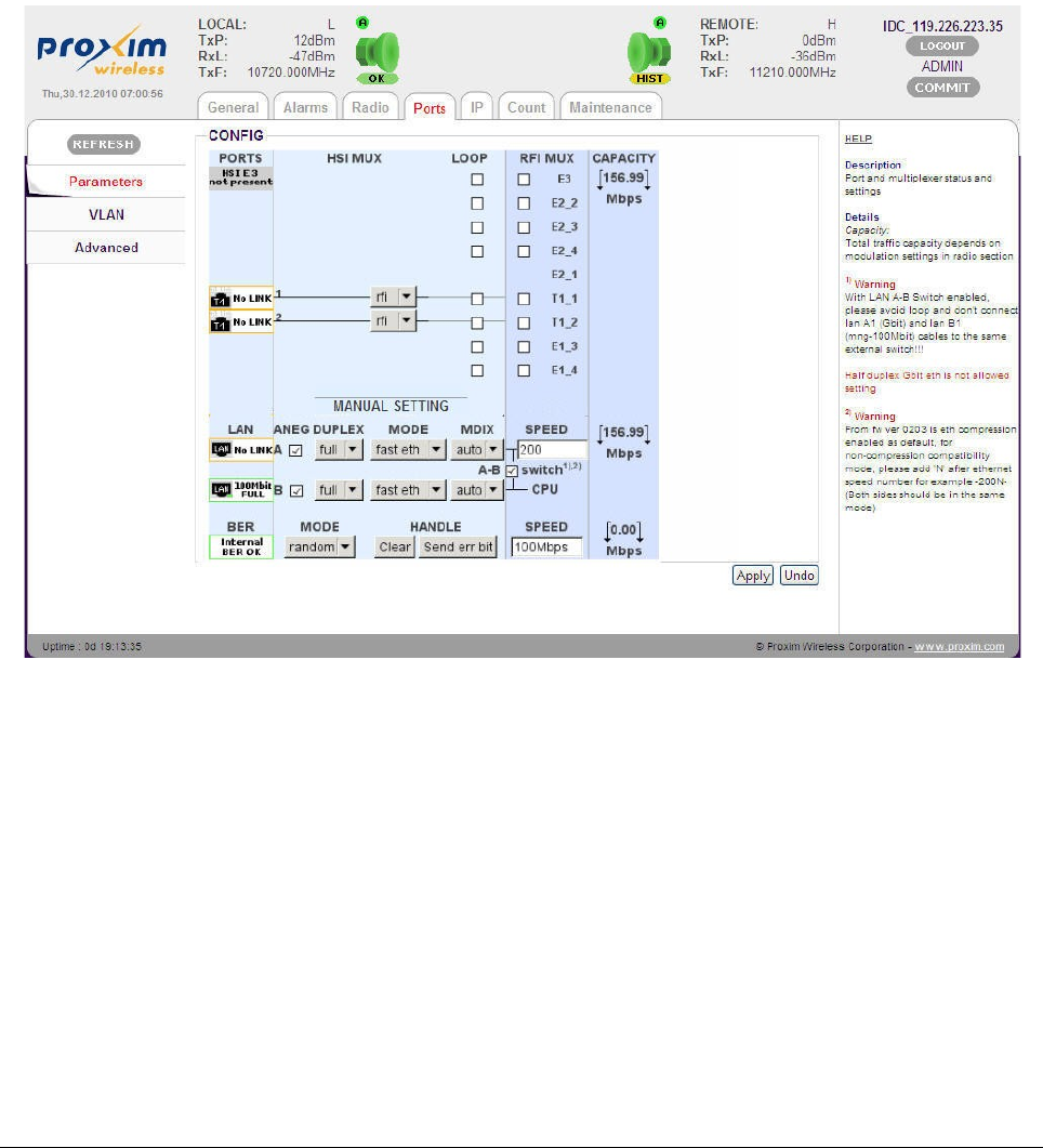
Interconnection of LAN A-B Ethernet Switches
For management through the Gigabit Ethernet port, it is necessary to enable (check) the
interconnection of LAN A-B switches in both IDUs and set a minimum data rate (1Mbps) on
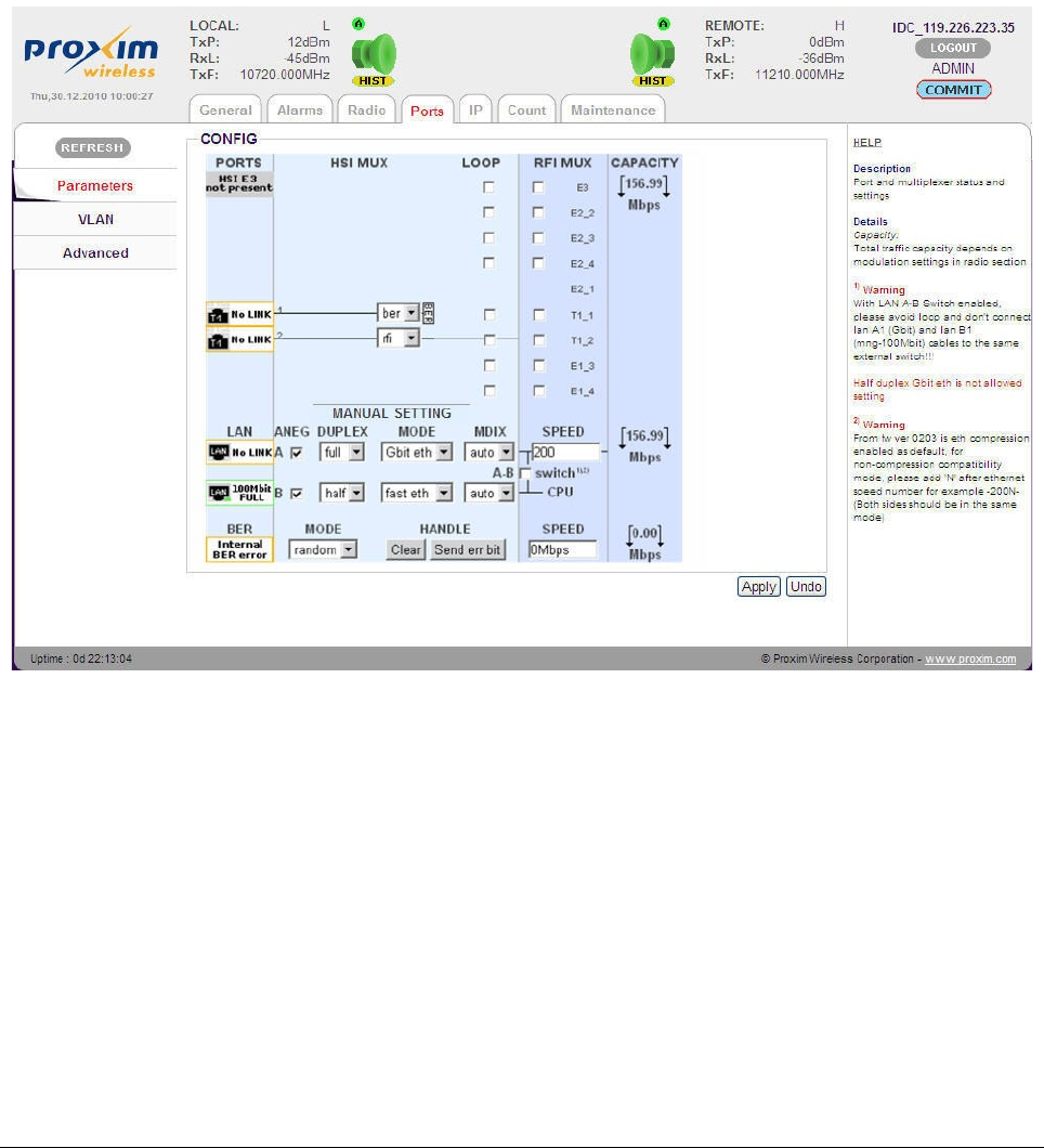
Ethernet. To configure this setting, navigate to main “Ports” and sub-menu “Parameters”.
In the above screen, do the following:
1. Check LAN A-B switch
2. Enter Ethernet speed (example 200Mbit) in the LAN SPEED box
3. Click Apply.
4. Click “COMMIT” to save the configured parameters.
Configure the same settings on the remote IDU2 as well.
Tsunami™ GX800 Installation and Management Guide 27
Figure 28: Enabling LAN A-B Ethernet Switches
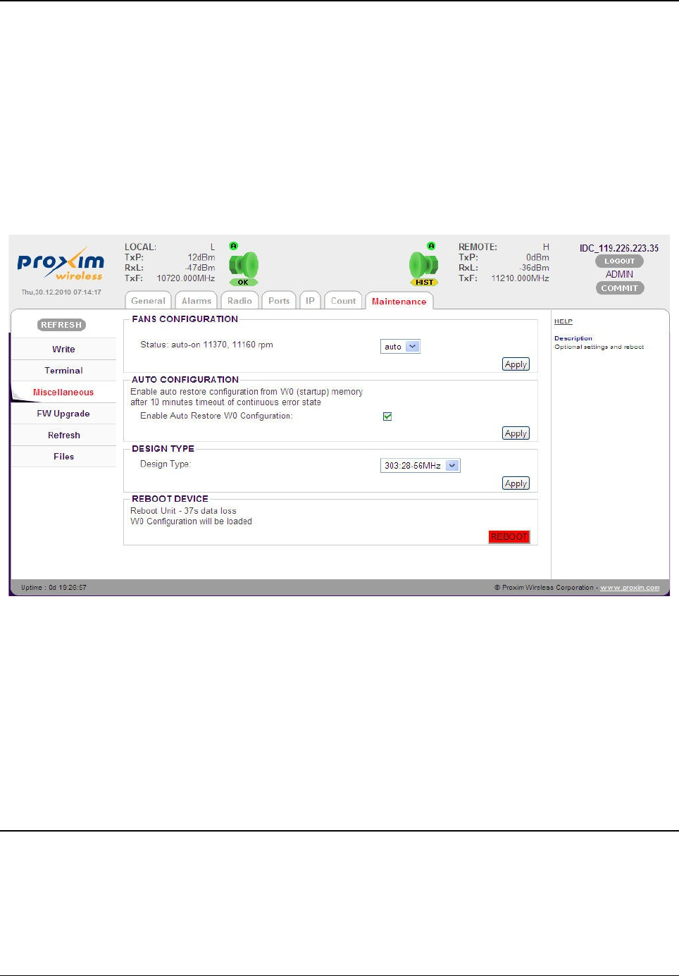
Dual License - Design Type Setup
For all the modulations schemes and bandwidths, Proxim provides one unified firmware (from
version 0207 and higher).
The firmware support two design types:
•Design type 301, which permits to switch between bandwidths in the range 7 – 30MHz
•Design type 303, which permits to switch between bandwidths in the range 28 – 56MHz
The firmware adapts automatically to uploaded license file in the device.
To configure these parameters, navigate to main menu “Maintenance” and sub-menu
“Miscellaneous”.
After configuring the parameters, click Apply.
Click “COMMIT” to save the configured parameters.
!! Note !! IDU with license for 301 design only (Bandwidth 7 – 30MHz) can work with IDU
with license for 303 design and also these IDUs should run on the specific modulations.
The modulations with “b” index in 303 design can work with the same modulations in 301
design. Example, qam128_28e6_02b 163,24Mbps
Frequency, Modulation and ATPC Setup
The set modulation scheme and the channel bandwidth affects the final data rate (data
throughput) and sensitivity (bridging distance) of GX800 link. Generally, the narrow the band and
lower modulation, the greater the sensitivity.
There are also used self-correcting codes in the modulations. It is the rule that in the same type
Tsunami™ GX800 Installation and Management Guide 28
Figure 29: Design Type
of modulation with a lower data rate there is better self-correcting security and thus a better
sensitivity (revision _01 or _02).
Depending on the type of supplied license (limit for maximum data rate) the modulation type can
be changed (type of modulation can be set / changed up to a maximum transmission capacity).
Microwave link can be ordered in the different licenses in accordance with actual price list and
business policy. Than the transmission capacity can be changed in the range from 10Mbps up to
a maximum data rate of supplied license, maximum 310Mbps.
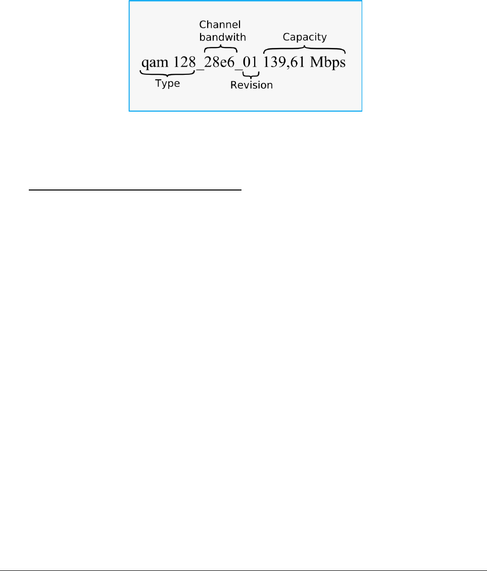
The modulations are named according to the combination of all the parameters as shown in the
following figure.
To setup the demanded Actual Modulation and Adaptive Modulation (ACM), navigate to main
menu “Radio” and sub-menu “Parameters”. In the parameters screen, navigate to “MODEM
CONFIGURATION”.
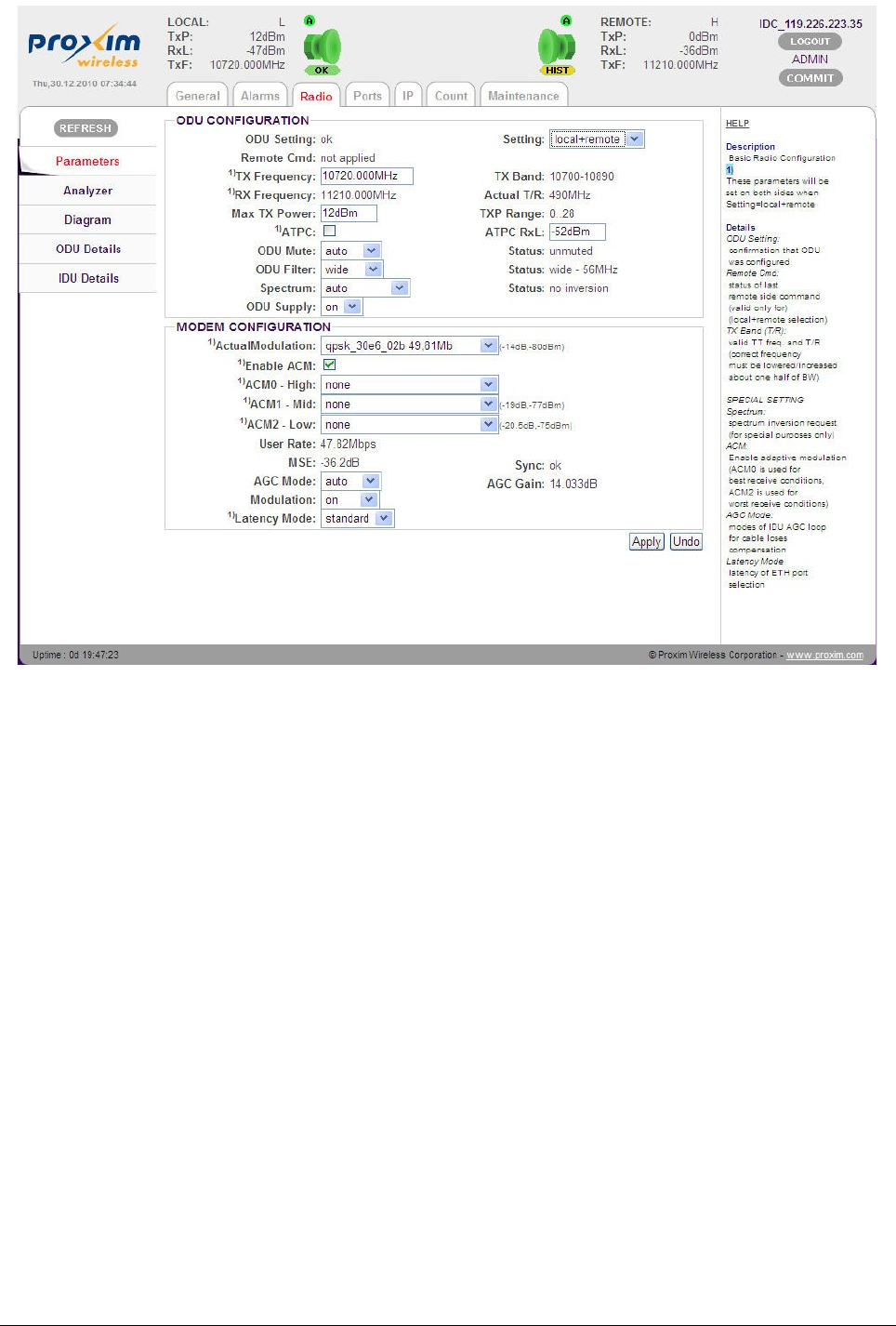
Actual Modulation Setup (without ACM):
The Actual Modulation parameter represents the current modulation. For a link without ACM
request, the desired modulation must be set directly in the Actual Modulation field as shown in
the following figure.
Tsunami™ GX800 Installation and Management Guide 29
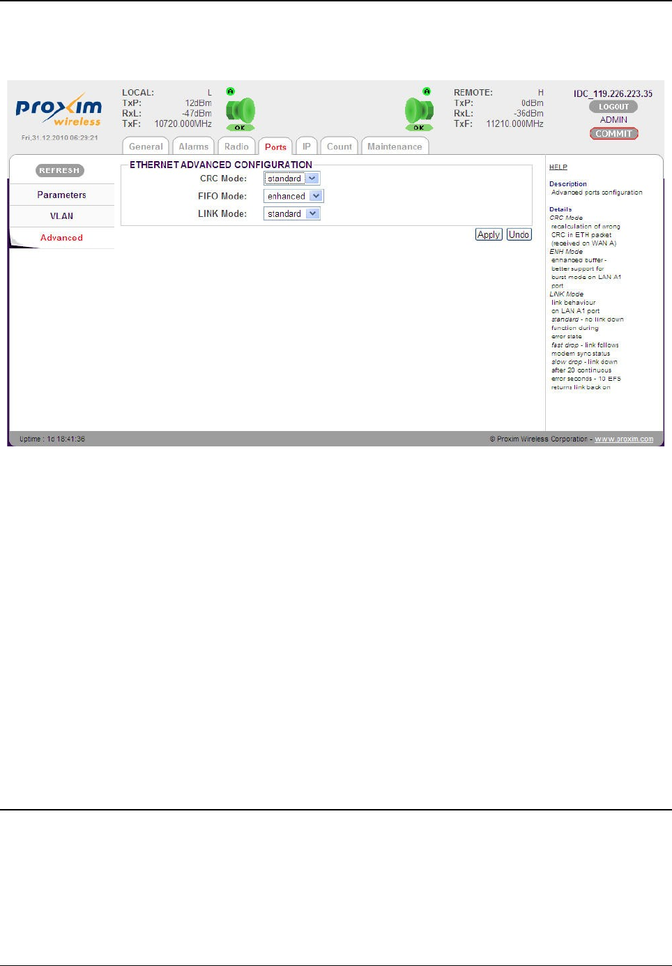
Adaptive Modulation Setup
ACM can be set by using the following three options:
•Adaptive Modulation 0 (ACM0) is for the highest throughput and the lowest security
•Adaptive Modulation 1 (ACM1) and 2 (ACM2) for the lower data throughput and better
security.
The desired ACM steps should be set at least in two fields ACM0 – ACM1 (see the following
figure). A user is allowed to set the ACM only when the Enable ACM box is unchecked. This
guarantees that the Actual Modulation setup could not be performed manually during the active
ACM.
Tsunami™ GX800 Installation and Management Guide 30
Figure 30: Modulation Setup without ACM
After setting the ACM parameters, check the Enable ACM parameter and click Apply. On doing
so, all the ACM parameters turn Grey. The currently modulation (Actual Modulation) is compared
with the ACM options (ACM0-2). If the current modulation is included in the ACM options, the
system will continue with this modulation without any drop-out (if it is not ACM0, the system will
keep evaluating whether the modulation scheme could not be switched to higher ACM option
(Example, from ACM1 to ACM0).
If the current modulation is not included in ACM options, the Actual Modulation will be switched to
ACM0 option.
!! ATTENTION !! For proper operation of ACM, at least two ACM options (ACM0 and ACM1)
must be selected. The rule is that ACM0 modulation is higher than ACM1 and ACM2!!
The same modulation (ACM options) must be set on both sides of the link.
!! Note !! The ACM can be configured by using either 301 or 303 design types. See Dual
License - Design Type Setup
Click “COMMIT” to save the configured parameters.
Tsunami™ GX800 Installation and Management Guide 31
Figure 31: Modulation with ACM
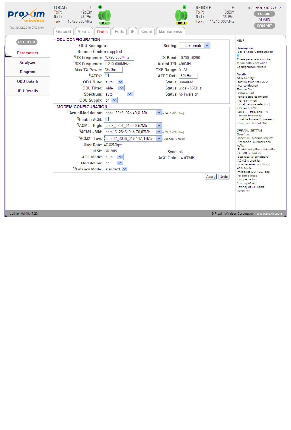
Ethernet Advanced Configuration
To configure advanced Ethernet configuration, navigate to main menu “Ports” and sub-menu
“Advanced”.
You can configure Gigabit Ethernet in the following modes:
•CRC Mode: Recalculates wrong CRC in Ethernet packets that are received on WAN A.
When set to standard, the error packets are discarded. When set to force, the CRC
calculation is done on the received packets.
•FIFO Mode: Enhanced buffer with better support for burst mode on LAN A1 port.
•LINK Mode: Represents the link behavior on LAN A1 port.
•standard – Standard mode without any dependency on the radio link status on
the Ethernet port behavior.
•fastdrop – Ethernet port is set to mute (link status of local IDU and remote
SWITCH port is “no-link”) when loss of synchronization of the link occurs (it
duplicates the Modem Sync. Status).
•slowdrop – Ethernet port is set to mute (link status of local IDU and remote
SWITCH port is “no-link”) after 20 continuous error seconds and it is returned
after 10 continuous error-less seconds.
Data Rate Settings for Connected User Interfaces
The data rates for connected interfaces can be set to a maximum transmission data rate over
GX800 link.
The following two examples depict the interface setup possibilities.
Tsunami™ GX800 Installation and Management Guide 32
Figure 32: Ethernet Advanced Configuration
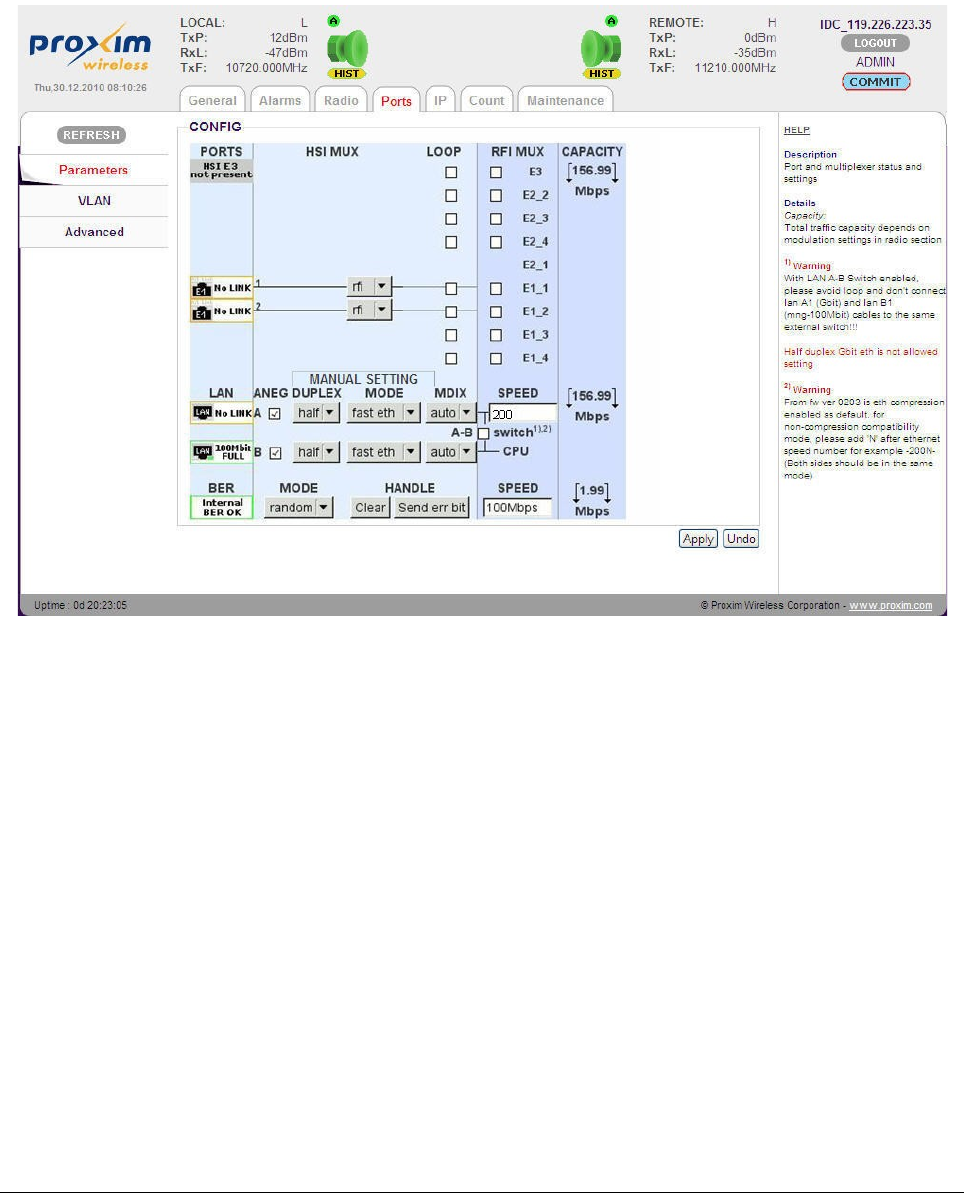
Example 1
For Ethernet transmission, with a modulation scheme 128QAM and bandwidth 28MHz, the real
user data rate is 156.99Mbps and the real data throughput is 163.24Mbps.
In the Web Browser, navigate to main menu “Ports” and sub-menu “Parameters” and set the
LAN SPEED as 200 Mbps (the overall capacity is allocated to Ethernet data, which is
156.99Mbps; no other interface is detected).
In the similar way, set the same values on the other side of the link.
Example 2
For Ethernet + 1xT1 transmission, with a modulation scheme 128QAM and bandwidth 28MHz,
the real user data rate is 156.99Mbps and real data throughput is 163.24Mbps.
The inserted HSI module is automatically detected and displayed with graphical interconnection
between PORTS and available RFI MUX channels as shown in the following figure.
Tsunami™ GX800 Installation and Management Guide 33
Figure 33: Data Rate
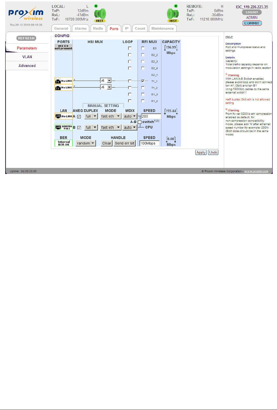
Check the box T1_1 to map available T1_1 channel onto T1 port. The T1 signal then takes
1.55Mbps from overall available user data rate. Remaining 155.44Mbps is allocated to Ethernet
data. (Make sure “rfi” option is selected.)
Set Ethernet LAN SPEED to 200 Mbps (the remaining capacity (155.44Mbps) will be allocated to
Ethernet data)
In the similar way, set the same values on the other side of the link.
Click “Apply” to commit the configured values.
Click “COMMIT” to save the configured parameters.
Tsunami™ GX800 Installation and Management Guide 34
Figure 34: Setting Connection Data Channels
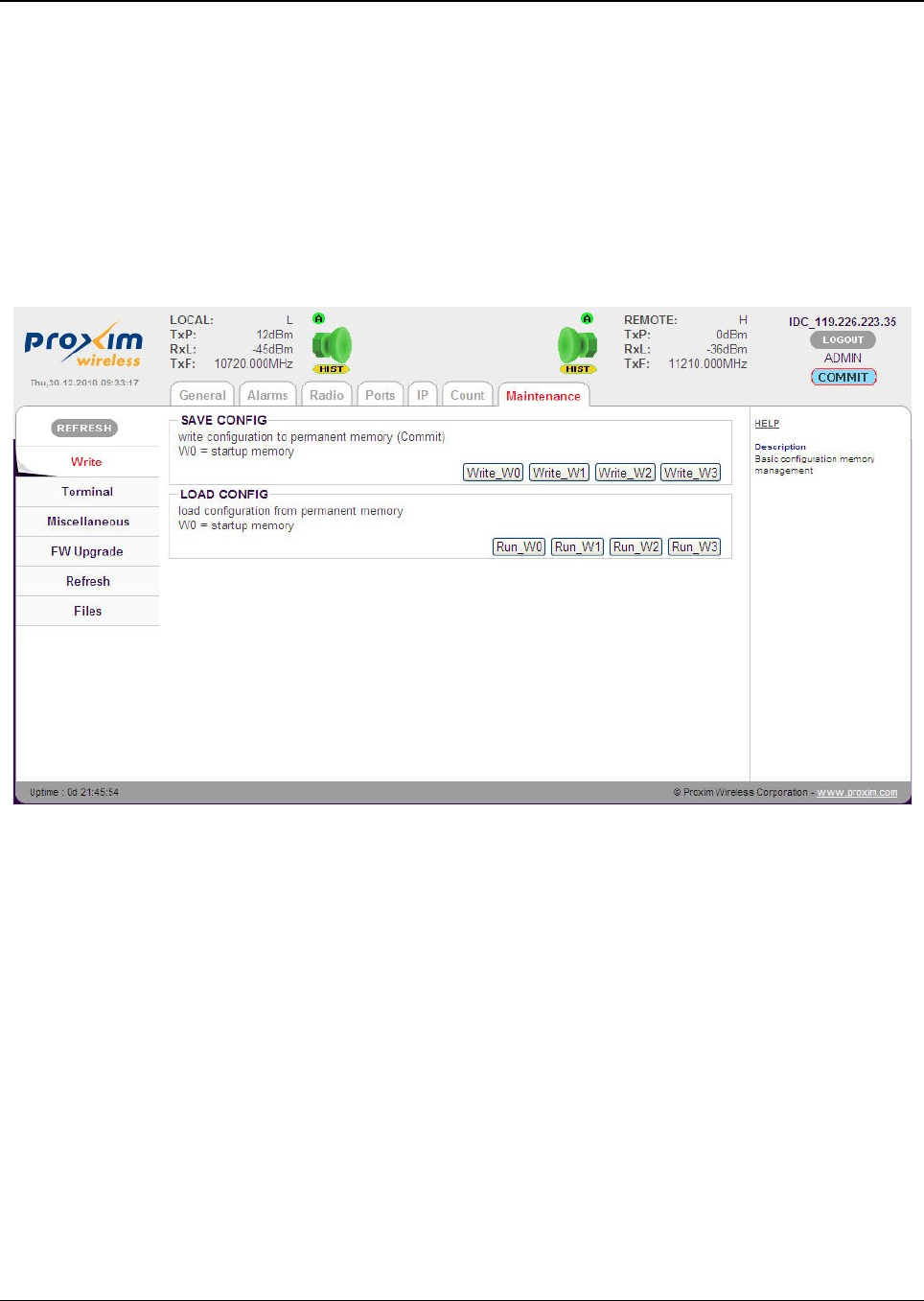
Save Configured Parameters
The configured parameters must be saved, so that they are valid even after the device restarts.
The IDU contains four memories. The first memory, referred to as W0, is the boot memory.
During the device startup, the link parameters are uploaded from this memory. The remaining
memories, referred to as W1, W2 and W3, can be used for configuration backup, testing
configuration and so on.
IP configuration is saved independently into W0 reboot memory only. IP configuration could be
saved either immediately after the IP setup or later in Web Interface under main menu
“Maintenance” menu and sub menu “Write“.
For saving into the memory, click the relevant button Write_W0 to Write_W3.
!! Note !! To save configuration parameters, you can also click the “COMMIT” button
which is available on the top of every screen.
Save the new configuration into the relevant memory (Example boot memory W0) on the other
side of the terminal as well.
To run any saved configuration, click relevant button Run_W0 to Run_W3.
Tsunami™ GX800 Installation and Management Guide 35
Figure 35: Save Configured Parameters
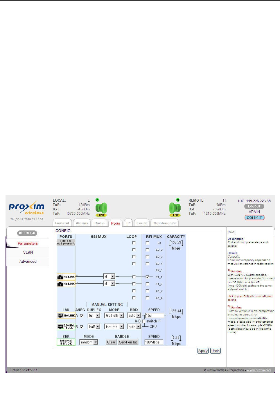
BER Test – GX800 Link and User Lines Verification
Bit Error Rate (BER) test is used to test and verify the quality of GX800 link and the connected
user lines by using internal BER tester.
GX800 BER Test:
A)
We recommend to allocate the full transmission capacity of GX800 to BER test for a limited
period of time. This way, even accidental and momentary errors can be detected. Switch off the
connected user interfaces (check out RFI MUX) and set:
LAN SPEED: 0 Mbps (no capacity for Ethernet)
BER SPEED: 100 Mbps (corresponding to maximum BER test data rate)
B)
During the vivid link operation, it is necessary to allocate least fractional capacity to run the BER
test.
Navigate to main menu “Port” and sub-menu “Parameters” and configure the following
parameters:
•RFI MUX
•LAN SPEED
•BER SPEED
Tsunami™ GX800 Installation and Management Guide 36
Figure 36: BER Test Setup during the Vivid Link Operation
!! Note !! For BER test, configure the parameters on both the terminals equally.
After configuring the parameters, click Apply.
User Line BER Test:
For the user line BER test, the full capacity of the line is devoted to BER tester. The BER signal is
directed to the selected channel and sent in the direction of HSI module of the IDU. Use loop on
the line to bring the signal back and verify the line quality.
Select the “ber” option instead of “rfi” in roll down menu of relevant user interface in HSI MUX
section of the following figure:
Next, to monitor the running BER test on GX800 link or user line in the Web Interface, navigate
to main menu “Count” and sub-menu “BER”.
Tsunami™ GX800 Installation and Management Guide 37
Figure 37: BER Test Setup for User Interface
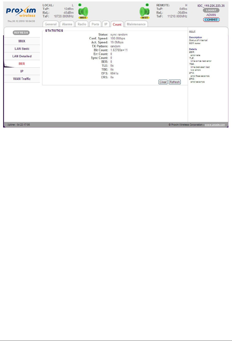
The STATISTICS screen is displayed which contains the following information:
•Status: Indicates the sync status and the received BER pattern
•Conf. Speed: Capacity set for BER tester
•Act. Speed: Real data rate dedicated for BER (automatically adjusted data rate)
•TX Pattern: Set of BER frame type (has to be set the same on both sides)
•Bit Count: Overall transmitted bits
•Err Count: Overall error bits
•Sync Count: Number of synchronizations since the last counters clearance
•BER: Error rate
•TLE: Time since last error occurrence
•TBE: Time between last two errors
•EFS: Time of error-free traffic in seconds
•ERS: Time elapsed while the link failed in seconds
Data Evaluation:
Clear the BER tester counters and check the results by clicking Refresh button.
For proper functioning of GX800 link, the values of EFS parameter, ERR Count, Sync Count,
BER, TLE, TBE and ERS parameters should be equal to zero.
If the test results vary, and the link (line) fails, it is necessary to verify the link installation and
configuration (verification of connected user line).
For GX800 link test, the same results must be read on both sides of the link.
Tsunami™ GX800 Installation and Management Guide 38
Figure 38: BER Tester Information

Analysis of Interference in GX800 link
Integrated Spectral Analyzer is a suitable tool for finding free channels in a given frequency band,
eventually for link interference. For licensed bands, you can use the Analyzer for the free
frequency verification.
Spectrum Analyzer is available in ADMIN and USER mode.
Frequency Analysis at Local Side:
Before finding if the given frequency spectrum is free or occupied, you have to mute the
transmitter on one side (ideally remote side). Exercise care as this will cause drop out of user
data transmission.
Login to remote device and mute the transmitter for a specified period of time with an automatic
revival. The interval for mute could be set from 1 to 3600 seconds. The remote unit will start
transmitting again automatically as the specified time elapses.
Navigate to main menu “Radio” and sub-menu “Analyzer”, and enter the time in seconds and
click Mute ODU button.
Tsunami™ GX800 Installation and Management Guide 39
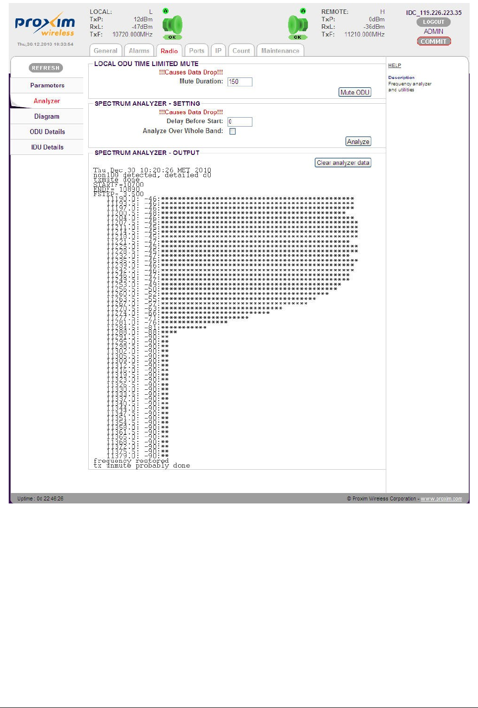
Next, click Analyze to start the spectrum analysis at the local terminal. In licensed bands, the
Analyze over whole band option causes analysis through the whole spectrum with a wider
frequency spacing (14MHz), otherwise the analysis is made in 56MHz range only around the RX
frequency with spacing 3.5MHz.
Frequency Analysis at Remote Side:
It is also possible to set a pause before scanning the spectrum. This is suitable for analyzing the
remote device. Set the pause (for example 10 seconds and click Analyze at remote side – this
will disconnect the management between the terminals and start the analysis after the specified
period of time (pause).
Tsunami™ GX800 Installation and Management Guide 40
Figure 39: Spectrum Analyzer Setup and Output

Before the pause at remote side elapses, click Mute ODU on local side for a specified period of
time (example 150 seconds) and wait for the analyze to finish. After that, the units should
interconnect again and the management of remote unit will be possible again. Finally, check the
frequency analyze at remote side.
!! Note !! Spectrum analysis for licensed bands last approximately for 150 seconds.
During this time, no data passes through the link.
Firmware Upgrade, License Upgrade
!! Note !! An ADMIN user alone can upgrade the firmware and the license.
For every firmware release, it is not necessary to update all the parts, but only the ones which
require an upgrade.
Basic Firmware Parts:
•hwbase.afw – Software for internal hardware parts
•oskernel.afw – Operating system
•dev.afw – Drivers for the Operating System
•fwbase.afw – Application software (WEB, SNMP, commands and so on)
Additional Firmware Parts:
•patch001.afw – Patch for enhancing the maximum length of the uploaded file. Applicable
for firmware upgrades from versions 0208_02 onwards.
•checkversions.afw – Compares the firmware version with the newest version and prints
the info that is necessary to upload.
•fw_all.afw – Compares the current version of firmware with the newest version and
automatically uploads the different parts (used only from firmware 0208_02 or package
patch001.afw).
Recommended Steps for Firmware Upgrade:
1. Log on to the web browser with ADMIN rights.
2. Click “COMMIT” (available on the top-right corner of each page) to save the current
configurations. Alternatively, you can save the configured parameters by navigating to
main menu “Maintenance” and sub-menu “Write” , and click “Write_WO”. By doing so,
the configurations are stored in the start-up memory.
3. Compare currently running versions of each firmware parts (oskernel.afw, dev.afw,
hwbase.afw and fwbase.afw) with the newest version by following one of the two below
steps:
•Manually compare data shown in main menu “General” and sub-menu
“Revision” with the file version.txt.
•Navigate to main menu “Maintenance” and sub-menu “FW Upgrade”, and
select the file checkversions.afw. Take a print-out and check the parts that
need to be upgraded.
Tsunami™ GX800 Installation and Management Guide 41
4. Alternatively, navigate to main menu “Maintenance” and sub-menu “FW Upgrade”, and
select the file patch001.afw (if it is required) and increase the maximum limit size for the
file upload.
5. Navigate to main menu “Maintenance” and sub-menu “FW Upgrade” and choose one of
the following steps:
•Select the file fw_all.afw from the provided software package. The entire file will
be uploaded into the device, compares the different versions and writes the
different parts of the firmware into flash memory. Please note that this procedure
is not suitable for slow connections.
•Gradually select the files hwbase.afw, oskernel.afw, dev.afw and fwbase.afw in
this order (if there is not necessary to upload any part, please continue with
another file) and wait for the process completion.
6. Once the files are uploaded, restart the device by navigating to main menu
“Maintenance” sub-menu “Miscellaneous” and click REBOOT. Please note that while
restart there is data transmission outage for about 35 seconds.
!! Note !! Upgrade the firmware files in both the terminals.
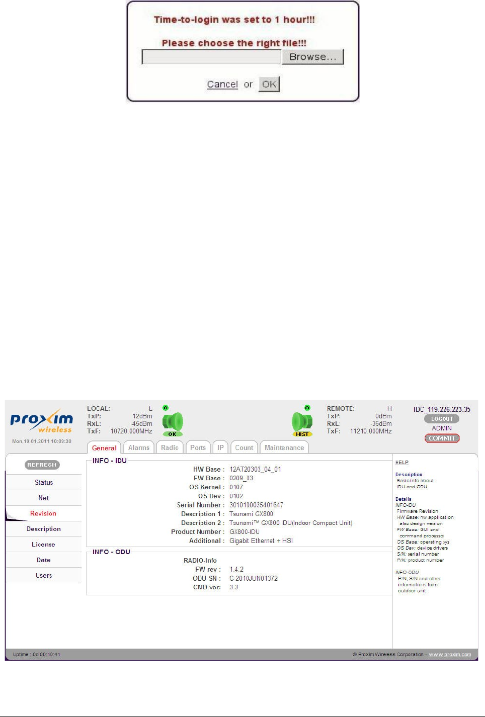
To view firmware details, navigate to main menu “General” and sub-menu “Revision”.
Tsunami™ GX800 Installation and Management Guide 42
Figure 40: Alert Window for Firmware Upload
Figure 41: Firmware Revision
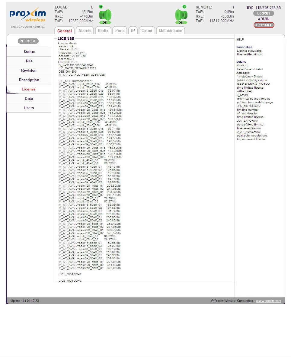
Upgrading the License
The license key comprises the list of available modulation schemes and bandwidths. Each
license key is unique for each IDU with respect to SN number of the IDU.
To find the SN of the IDU where the license key will be uploaded, navigate to main menu
“General” and sub-menu “License”.
The SN is in the line:
S_N=xxxxxxxxxxxxxxxx
Tsunami™ GX800 Installation and Management Guide 43
Figure 42: IDU license Information

Compare the SN of IDU with license key which appear as: licxxxxxxxxxxxxxxxx.afw
The string of “x” is the serial number of device for which the license key is generated.
The license upgrade is performed the same way as firmware upgrade described above.
Restart the IDU after the license upgrade. To restart, navigate to main menu “Maintenance” and
sub-menu “Miscellaneous” and click REBOOT.
Alarms
GX800 generates the error messages (events) indicating its status and events. You can use an
SNMP application to get these messages and events so that you can monitor your link or
network.
Tsunami™ GX800 Installation and Management Guide 44

Number Title Description
600 g703 p1 link No valid E1 signal on p1 port
601 g703 p1 ais Detecting sequence “1” (according to the ITU G.755 norm for E1)
on p1 port
602 g703 p2 link No valid E1 signal on p2 port
603 g703 p2 ais Detecting sequence “1” (according to the ITU G.755 norm for E1)
on p2 port
632 lana1 link No valid signal on LAN A1 port (Gigabit user data port)
636 lanb1 link No valid signal on LAN B1 port (100Mbit management port)
640 hsi los Failure of frame/packet synchronization on HSI interface
(fiber/4W)
641 hsi fer Frame failure of HSI interface over limit
644 mse low Bad MSE (SNR) – threshold can be set
649 mod los Failure of frame/packet synchronization on modem interface
650 rfi los Failure of frame/packet synchronization on packet based
multiplexer (modem)
651 rfi fer Frame failure of RFI interface above limit
652 idu_temp Temperature of indoor unit is above limit (-5 through 60°C)
653 odu_temp Temperature of outdoor unit is above limit (-25 through 60°C)
654 odu_RxL Received level of outdoor unit above limit
655 odu_comm Error while communicating with outdoor unit
656 odu_alarm Outdoor unit has non-zero alarm byte
657 license err License problem
658 safe design N/A for HS – backup system run
659 reset Reset underway
660 hw error Hardware error – with older units set mask of hardware presence
(after firmware update), or servicing by Proxim necessary
661 sw error Software error – try restarting, update firmware and restart
662 system error Non-specified system error – contact Proxim
Example of the printout:
E 649 192.168.3.52 GX800 mod_los Tue Jan 6 05:45:20 2009
event_status – event_ID – IP_address – device_type – event_ name – date_and_time
SNMP Settings
The system permits to set a maximum of three IP addresses to which the SNMP traps will be
sent.
To set the IP addresses, navigate to the main menu “IP” and sub-menu “SNMP”.
Tsunami™ GX800 Installation and Management Guide 45
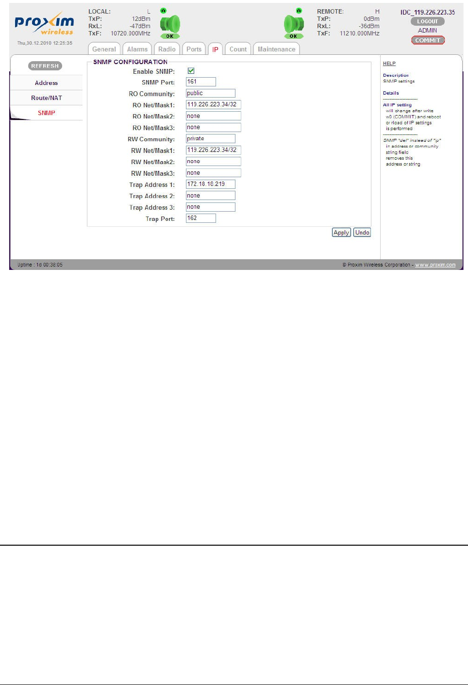
The SNMP configurable parameters are,
•Enable SNMP: Indicates the access rights of an SNMP agent
•SNMP Port: Port number for IP-SNMP access
•RO Community: Community string for read-only access
•RO Net/Mask1-3: Accessible address/net for read access
•RW Community: Community string for write access
•RW Net/Mask1-3: Accessible address/net for write access
•Trap Address1-3: IP address for SNMP traps distributions
•Trap Port: Port number for IP-SNMP Trap messages
After configuring the parameters, click Apply.
Click COMMIT to save the configured parameters.
IP Management
To access the management port, use either the connection via 10/100 Fast Ethernet port, which
is connected to the switch B, or with the LAN A-B switch interconnection set (LAN A-B switch on)
or by means of a 10/100/1000 Gigabit Ethernet port. Other ports on the CPU are primarily used
for connecting remote IDU or remote external device.
In-Band Management through Gigabit Ethernet port
In the simplest case, it is possible to supervise the entire system from one or both sides of the
link via the Gigabit Ethernet port(s). The management data together with the user data are
Tsunami™ GX800 Installation and Management Guide 46
Figure 43: SNMP
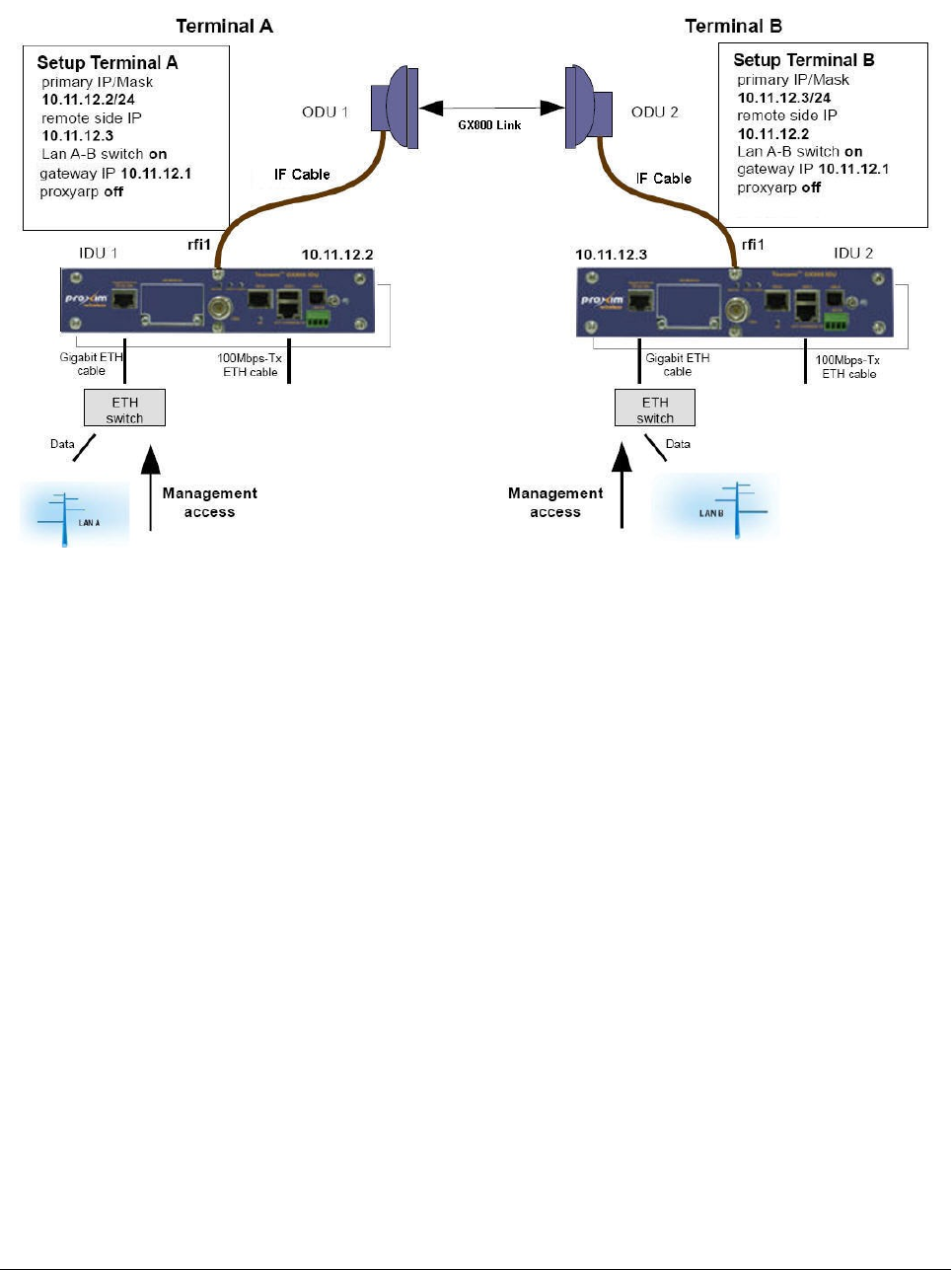
brought via the common Gigabit cable from the external Ethernet switch to IDU (see IDU1 and
IDU2 in Figure 44 below).
Given below is an example which illustrates the connection of individual management ports in the
IDUs along with the method to configure IP settings of both the IDUs.
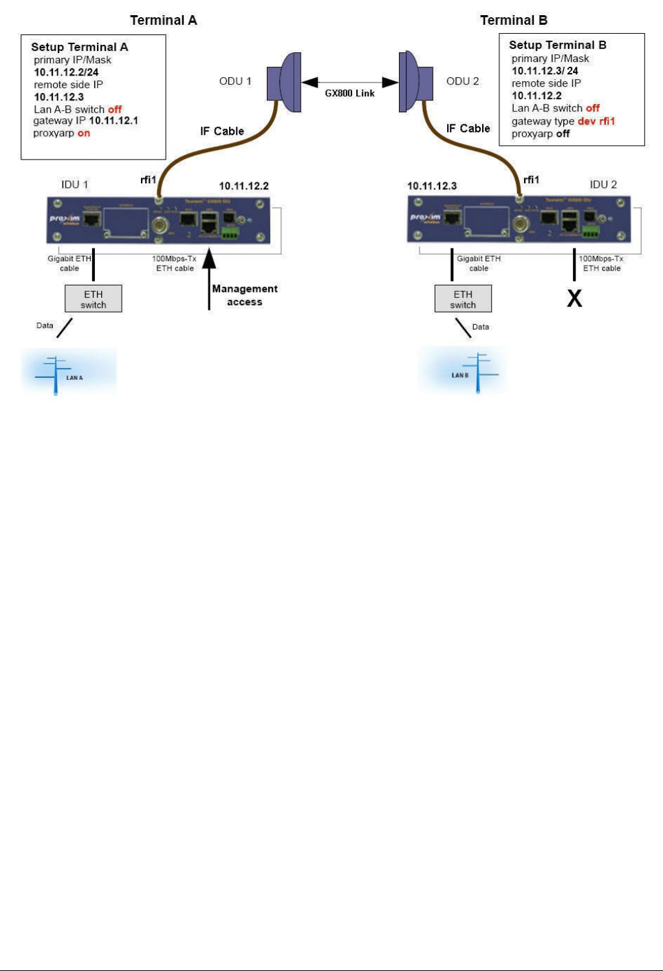
Out-of-Band Management through Fast Ethernet Port – Access from one
side
Another option is to supervise the entire system from one side of the GX800 link separately from
the user data through Fast ETHERNET port. The management data are brought independently
from user data into the management port in IDU. Connect management PC into the Fast
ETHERNET port on side A.
Given below is an example which illustrates the connection of individual management ports in the
IDUs along with the method to configure IP settings of both the IDUs.
Tsunami™ GX800 Installation and Management Guide 47
Figure 44: In-Band Management through Gigabit Ethernet Port
By modifying this configuration, we can get limited access also from the second side of the link.
For example, by setting the mask on the B-side to 30, the IP of the management PC on B-side
will be 10.11.12.4/30 and it will have the gateway set to 10.11.12.3. Then set the static route of
the device for the management PC on the A-side:
via IP/dev rfi1: dev rfi1
Routed IP/MASK: 10.11.12.4
Out-of-Band Management over Fast Ethernet Port – Standard Routing
Scheme (two independent subnets)
For management access from both the sides of the link (where management data is separated
from the user data) it is necessary to observe the rules of static routing. Further, it is necessary to
have the IP addresses from different subnets on each side of the link. This technique is the most
complicated, but the most neat one in terms of complex network projects. The block diagram of
IDU in terms of IP is shown in the following figure.
Tsunami™ GX800 Installation and Management Guide 48
Figure 45: Out-of-band management over Fast ETHERNET port – Access from one side
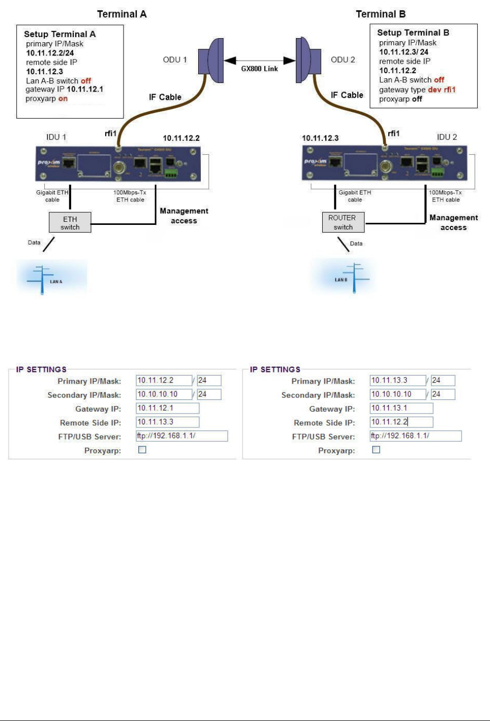
The figure below indicates the IP settings for both the IDUs. The device A is in the subnet
10.11.12.xx/24 and the device B is in the subnet 10.11.13.xx/24.
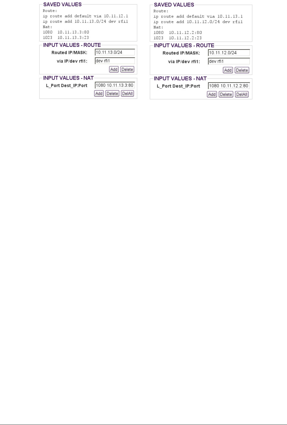
The example of adding NAT and route rules is shown in the following figure.
Tsunami™ GX800 Installation and Management Guide 49
Figure 46: Out-of-Band Management over Fast Ethernet Port
Figure 47: IP setup for device A (left) and device B (right)
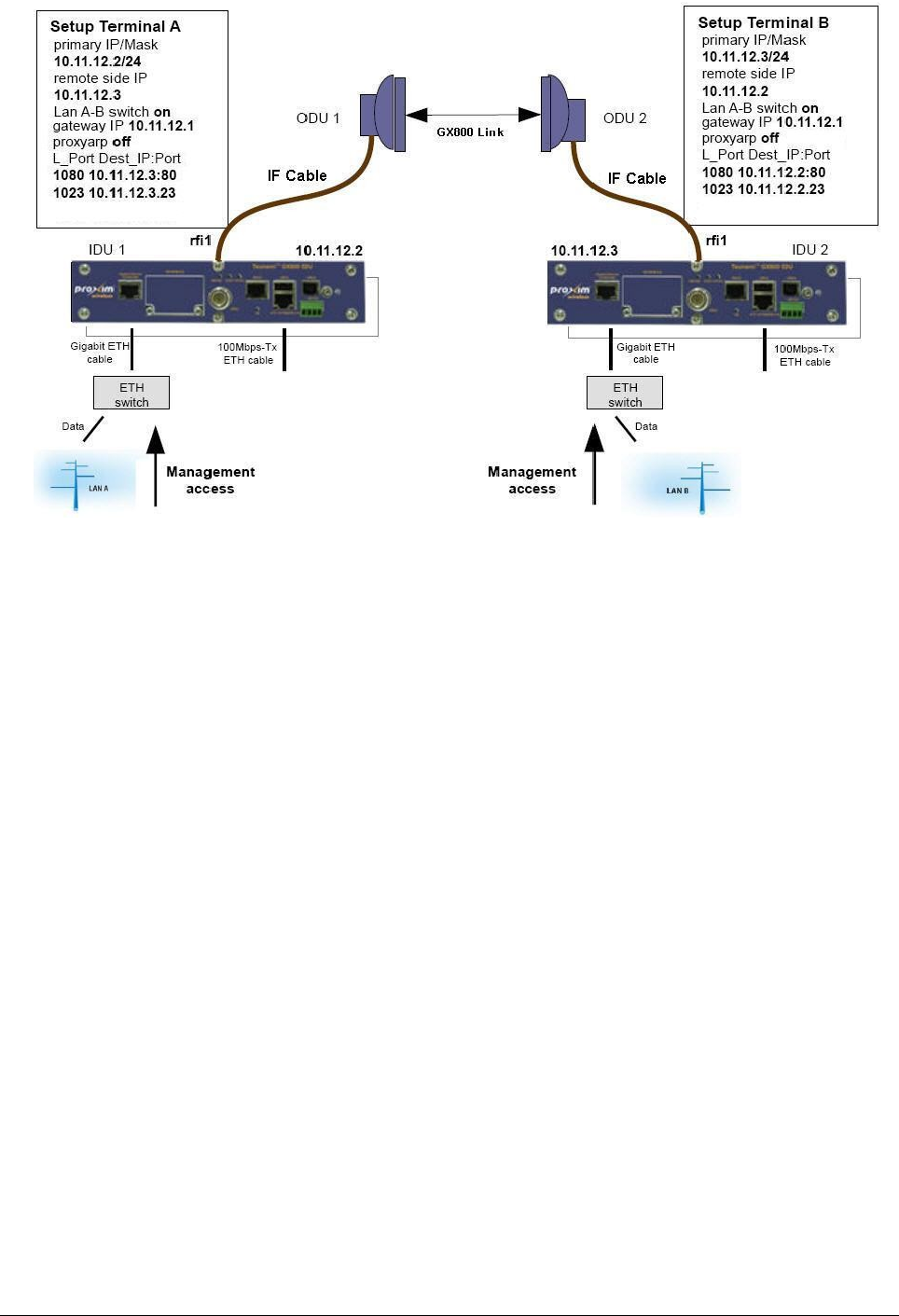
In-band and Out-of-band Management – NAT
The simplest and the most recommended solution is a combination of in-band and out-of-band
management. This solution permits access from one or both sides of the link via Gigabit
ETHERNET port and also from Fast ETHERNET port (beware of and avoid possible loop on
Ethernet).
The remote device can be managed via In-band management and Out-of-Band management.
In In-band management, the management traffic flows with the regular wireless user traffic. For
example, direct access of the remote device by using remote device's direct IP address.
In out-of-band management, the management traffic will flow in a separate RFI channel and not
as part of regular user traffic. For configuring the out-of-band management, you need to
configure to access the remote device access on ports defined in NAT rules in the local device.
The following figure illustrates the connection of individual management ports in the IDUs along
with the method to configure IP settings of both the IDUs.
Tsunami™ GX800 Installation and Management Guide 50
Figure 48: Static Routes and NAT Setup for device A (left) and device B (right)
Tsunami™ GX800 Installation and Management Guide 51
Figure 49: In-band and Out-of-band Management – NAT

Chapter 5 Troubleshooting
User Login Problems
A user logs out from the application without LOGOUT only when another user logs in and kill the
current user. Please note that an Administrator user can kill USER/GUEST but vice-versa is not
applicable.
To avoid login problems, do not use browser's “back“, “forward” or “refresh” buttons but only the
links and buttons of the web interface.
A user might log out also when the link takes longer time to respond.
Login Problems While Device Restarts
•Web Interface: These problems occur when when the ODU is not connected and you
tried to login before the connection got established. When the device restarts, wait for
about 30-60 seconds, and then login.
•Command Prompt: When you try to login to the device after its restart using RJ45 to
RS232 interface and a message is displayed at prompt saying “no access”. This
happens probably when IDU does not communicate correctly with its own peripheries
including ODU (typically disconnected ODU). This status can last about 30 seconds. If it
happens for a longer period of time during the device operation, or if these commands
cause terminal “freezing”, use the command “reset killmonitor” (it causes shorter drop out
– approximately 5 seconds), or restart device (“reset system” - longer drop out –
approximately 35 seconds).
Problems in Communicating with the ODU
When you face these problems, disconnect the IF cable from ODU and measure voltage on the
ODU RF connector. The measure voltage should be same as IDU supply voltage (Depending on
the cable length, the maximal decline is -2 V). If it is not same then check the device
consumption. The IDU consumption together with ODU should be approximately 1 A.
Problems in Setting ODU Parameters
Before setting the ODU parameters (set rad txf and set rad txp) in the text mode, use “?” for
viewing adjustable values. Maximal output power of ODU depends on the type of modulation.
Problems with Modem Synchronization
Check the external Automatic Gain Control (AGC) which is the automatic adjustment of IDU gain
at receiving way (cable). The ideal value is between 4 to 16 dB. The more the value, the higher is
the IF attenuation. The displayed gain can be a maximum of 17.5 dB, which means:
1. No signal is received
2. ODU is not powered
3. Broken cable
Problems with Received Signal (Rx) level at ODU
Check whether the ODU parameters are properly set (the Tx frequency and Rx frequency should
be same on both the terminals, adequate output power and ODU is not muted) for both the IDUs.
Next, check for correct installation and antenna alignment (voltmeter on BNC connector).
Tsunami™ GX800 Installation and Management Guide 52

Problems with MSE
Check the received power at ODU. If it is OK, switch off the opposite ODU and scan the band
(Radio / analyzer). By this, you will find the background noise in a given band. If the problem is
not caused by noise, check the RF cable (connectors, shielding and so on).
Problems with Failing Link
Check the counters on RFI (Count / rfi/hsi), erase (button Clear) and check the counters on RFI
again. If there are errors (the frames are not counted, the error frames are counted) check MSE
(General / status – MSE) and Rx Level at ODU (General / status – Rx Level). If you still face
problem, follow the instructions as mentioned earlier.
Problems with Ethernet Connection
Check the setup (Ports / parameters) of LAN ports. The setup has to be the same as setup on
the opposite terminal (switch, PC, router and so on). Try to analyze the problem with the help of
frame counters (Count / LAN basic) and detailed counters (Count / LAN detailed).
Problems with IP Management
IP parameters get saved in the memory only after device reboot. Change in the IP address can
be a router problem (before change of arp table). You can display the actual adjusted
parameters including the counters by the command “sh IP stat” (count / IP), actual routers by the
command “sh IP route” (IP / route).
Use program “ping ip_address_of_your_device” from Personal Computer and trace counters via
Personal Computer serial console (“sh ip stat”). Use “ping ip_address_your_PC” from device and
trace counters; Use “ping ip_address_starting_gate”, eventually “ping
ip_address_device_with_the_same_subnet” and trace printout and counters. With incorrect
visualization of opposite device status, check the IP address setup of remote rfi (“sh ip conf”) (IP /
address).
Firmware Update Problems
•Do not downgrade firmware onto the device
•Always clear the web browser cache
Tsunami™ GX800 Installation and Management Guide 53
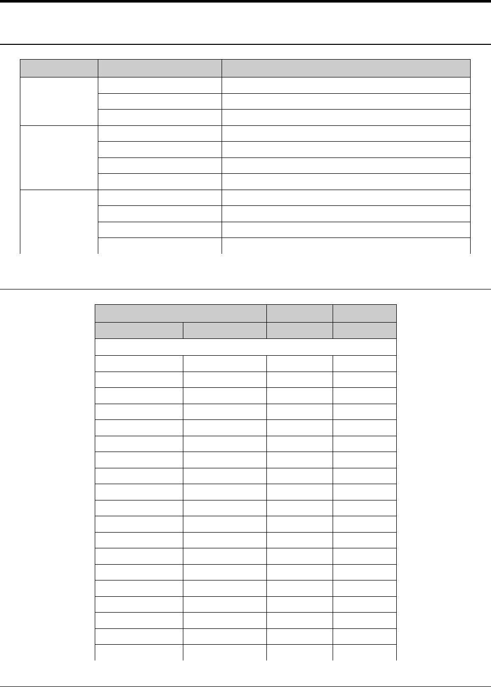
Chapter 6 - Technical Parameters
General
Item Parameter Value
Frequency Operating Frequency Range 6 to 38 GHz
Frequency Plans According to CEPT/ITU-R recommendations
T/R Spacing According to CEPT/ITU-R recommendations
Modulation Modulation Schemes QPSK, 16QAM, 32QAM, 64QAM, 128QAM, 256QAM
ACM Three step adaptive modulation (user-defined)
CEPT/ETSI Bandwidths 7/14(13.75)/28(27.5)/56 MHz
ANSI/FCC Bandwidths 10/20/30/40/50 MHz
Data
Transmission
Capacity Allocation Packet transport (priority based packet system)
Path Configuration 1+0
Forward Error Correction FEC, Predistortion, Equalization, Internal BER
Compression Function Online Ethernet header compression
Frequency Bands
Transmit Range1T/R Spacing Bandwidth
Minimum (MHz) Maximum (MHz) (MHz) (MHz)
6 GHz
5915.55 5989.675 252.04 74.125
6167.59 6241.715 252.04 74.125
5974.85 6048.975 252.04 74.125
6226.89 6301.015 252.04 74.125
6034.15 6108.275 252.04 74.125
6286.19 6360.315 252.04 74.125
6093.45 6167.575 252.04 74.125
6345.49 6419.615 252.04 74.125
5850 5946 300 96
6150 6246 300 96
5918 6014 300 96
6218 6314 300 96
5986 6082 300 96
6286 6382 300 96
6054 6150 300 96
6354 6450 300 96
6540 6600 160 60
6700 6760 160 60
6580 6640 160 60
Tsunami™ GX800 Installation and Management Guide 54

6740 6800 160 60
6620 6680 160 60
6780 6840 160 60
6660 6710 160 50
6820 6870 160 50
6540 6590 170 50
6710 6760 170 50
6580 6630 170 50
6750 6800 170 50
6620 6670 170 50
6790 6840 170 50
6660 6700 170 40
6830 6870 170 40
6425 6509 340 84
6765 6849 340 84
6481 6564 340 83
6821 6904 340 83
6536 6619 340 83
6876 6959 340 83
6591 6674 340 83
6931 7014 340 83
6646 6729 340 83
6986 7069 340 83
6701 6785 340 84
7041 7125 340 84
6425 6499 350 74
6775 6849 350 74
6481 6554 350 73
6831 6904 350 73
6536 6609 350 73
6886 6959 350 73
6591 6664 350 73
6941 7014 350 73
6646 6719 350 73
6996 7069 350 73
6701 6775 350 74
7051 7125 350 74
7 GHz
7093 7149 196 56
7289 7345 196 56
7121 7177 196 56
7317 7373 196 56
7149 7205 196 56
7345 7401 196 56
Tsunami™ GX800 Installation and Management Guide 55

7177 7233 196 56
7373 7429 196 56
7205 7261 196 56
7401 7457 196 56
7114 7177 161 63
7275 7338 161 63
7149 7212 161 63
7310 7373 161 63
7184 7247 161 63
7345 7408 161 63
7219 7282 161 63
7380 7443 161 63
7239 7302 161 63
7400 7463 161 63
7274 7337 161 63
7435 7498 161 63
7309 7372 161 63
7470 7533 161 63
7344 7407 161 63
7505 7568 161 63
7414 7477 161 63
7575 7638 161 63
7449 7512 161 63
7610 7673 161 63
7484 7547 161 63
7645 7708 161 63
7519 7582 161 63
7680 7743 161 63
7539 7602 161 63
7700 7763 161 63
7574 7637 161 63
7735 7798 161 63
7609 7672 161 63
7770 7833 161 63
7644 7707 161 63
7805 7868 161 63
7428 7484 154 56
7582 7638 154 56
7470 7526 154 56
7624 7680 154 56
7512 7568 154 56
7666 7722 154 56
7433.5 7496.5 160 63
7593.5 7656.5 160 63
Tsunami™ GX800 Installation and Management Guide 56

7478.5 7541.5 160 63
7638.5 7701.5 160 63
7526 7589 160 63
7686 7749 160 63
7443 7499 168 56
7611 7667 168 56
7485 7541 168 56
7653 7709 168 56
7527 7583 168 56
7695 7751 168 56
7400 7484 245 84
7645 7729 245 84
7484 7568 245 84
7729 7813 245 84
7568 7652 245 84
7813 7897 245 84
8 GHz
8279 8307 119 & 126* 28
8398 8426 119 & 126* 28
8293 8321 119 & 126* 28
8412 8440 119 & 126* 28
8307 8335 119 & 126* 28
8426 8454 119 & 126* 28
8321 8349 119 & 126* 28
8440 8468 119 & 126* 28
8335 8363 119 & 126* 28
8454 8482 119 & 126* 28
8349 8377 119 & 126* 28
8468 8496 119 & 126* 28
8043 8113 208 70
8251 8321 208 70
8099 8169 208 70
8307 8377 208 70
8155 8225 208 70
8363 8433 208 70
8211 8281 208 70
8419 8489 208 70
7905 8024 266 119
8171 8290 266 119
8017 8136 266 119
8283 8402 266 119
7731 7867 311.32 136
8042 8178 311.32 136
7835 7971 311.32 136
Tsunami™ GX800 Installation and Management Guide 57

8146 8282 311.32 136
10 GHz
10150 10300 350 150
10500 10650 350 150
11 GHz
10700 10890 490 & 500* 190
11200 11390 490 & 500* 190
10855 11045 490 & 500* 190
11355 11545 490 & 500* 190
11010 11200 490 & 500* 190
11510 11700 490 & 500* 190
10675 10855 530 180
11205 11385 530 180
10795 10975 530 180
11325 11505 530 180
10915 11135 530 220
11445 11665 530 220
11035 11215 530 180
11565 11745 530 180
13 GHz
12751 12814 266 63
13017 13080 266 63
12807 12870 266 63
13073 13136 266 63
12863 12926 266 63
13129 13192 266 63
12919 12982 266 63
13185 13248 266 63
15 GHz
14627 14732 315 105
14942 15047 315 105
14725 14844 315 119
15040 15159 315 119
14823 14928 315 105
15138 15243 315 105
14501 14613 420 112
14921 15033 420 112
14606 14725 420 119
15026 15145 420 119
14718 14837 420 119
15138 15257 420 119
14816 14928 420 112
15236 15348 420 112
14403 14522 490 119
Tsunami™ GX800 Installation and Management Guide 58

14893 15012 490 119
14515 14634 490 119
15005 15124 490 119
14627 14746 490 119
15117 15236 490 119
14739 14858 490 119
15229 15348 490 119
14500 14668 475 168
14975 15143 475 168
14660 14828 475 168
15135 15303 475 168
14715 14883 475 168
15190 15358 475 168
14500 14610 640 110
15140 15250 640 110
14605 14715 640 110
15245 15355 640 110
14400 14512 644 112
15044 15156 644 112
14498 14610 644 112
15142 15254 644 112
14596 14708 644 112
15240 15352 644 112
14500 14615 728 115
15228 15343 728 115
18 GHz
17685 17985 1010 & 1008* 300
18695 18995 1010 & 1008* 300
17930 18230 1010 & 1008* 300
18940 19240 1010 & 1008* 300
18180 18480 1010 & 1008* 300
19190 19490 1010 & 1008* 300
18400 18700 1010 & 1008* 300
19410 19710 1010 & 1008* 300
17700 18000 1560 300
19260 19560 1560 300
17840 18140 1560 300
19400 19700 1560 300
17700 18140 1560 440
19260 19700 1560 440
23 GHz
22000 22314 1008 314
23008 23322 1008 314
22286 22600 1008 314
Tsunami™ GX800 Installation and Management Guide 59

23294 23608 1008 314
21200 21600 1200 400
22400 22800 1200 400
21600 22000 1200 400
22800 23200 1200 400
22000 22400 1200 400
23200 23600 1200 400
21200 21500 1232 300
22432 22732 1232 300
21472 21786 1232 314
22704 23018 1232 314
21779 22093 1232 314
23011 23325 1232 314
22086 22386 1232 300
23318 23618 1232 300
26 GHz
25050 25250 800 200
24549 24871 1008 322
25557 25879 1008 322
24843 25151 1008 308
25851 26159 1008 308
25123 25445 1008 322
26131 26453 1008 322
1 These values indicate ODU tuning range and not center frequencies.
* Represents dual T/R Spacing supported by the software.
Receive Sensitivities and Emission Designator for
11GHz
Modulation name Modulation Bandwidth
(MHz)
Receive
Sensitivities
(dBm)
Capacity
(Mbps)
Emission
Designator
ETSI Modulations
QPSK_07e6_01 QPSK 7 -94.4 8.97 7M00D1D
QPSK_07e6_02 QPSK 7 -92.3 10.26 7M00D1D
QAM16_07e6_01 16QAM 7 -86.4 20.64 7M00D1D
QAM16_07e6_02 16QAM 7 -85.4 22.15 7M00D1D
QAM32_07e6_01 32QAM 7 -83.3 26.06 7M00D1D
QAM32_07e6_02 32QAM 7 -82.4 27.71 7M00D1D
QAM64_07e6_01 64QAM 7 -80.1 31.02 7M00D1D
QAM64_07e6_02 64QAM 7 -78.9 33.28 7M00D1D
QPSK_14e6_01 QPSK 14 -91.1 18.74 14M0D1D
QPSK_14e6_02 QPSK 14 -89.2 21.64 14M0D1D
Tsunami™ GX800 Installation and Management Guide 60

QAM16_14e6_01 16QAM 14 -83.7 40.05 14M0D1D
QAM16_14e6_02 16QAM 14 -82.6 42.98 14M0D1D
QAM32_14e6_01 32QAM 14 -80.6 50.1 14M0D1D
QAM32_14e6_02 32QAM 14 -79.3 53.75 14M0D1D
QAM64_14e6_01 64QAM 14 -77.2 60.14 14M0D1D
QAM64_14e6_02 64QAM 14 -75.9 64.52 14M0D1D
QAM128_14e6_01 128QAM 14 -72.1 75.3 14M0D1D
QAM128_14e6_02 128QAM 14 -71.8 76.57 14M0D1D
QPSK_28e6_01 QPSK 28 -86.3 38.88 28M0D1D
QPSK_28e6_02 QPSK 28 -85.1 44.23 28M0D1D
QAM16_28e6_01 16QAM 28 -82.6 73.1 28M0D1D
QAM16_28e6_02 16QAM 28 -80 85.57 28M0D1D
QAM32_28e6_01 32QAM 28 -77.2 104.18 28M0D1D
QAM32_28e6_02 32QAM 28 -76.2 110.76 28M0D1D
QAM64_28e6_01 64QAM 28 -75.3 128.55 28M0D1D
QAM64_28e6_02 64QAM 28 -72.9 134.06 28M0D1D
QAM128_28e6_01 128QAM 28 -73 134.25 28M0D1D
QAM128_28e6_02 128QAM 28 -70.1 156.99 28M0D1D
QAM256_28e6_01 256QAM 28 -67.8 168.78 28M0D1D
QAM256_28e6_02 256QAM 28 -66.5 179.43 28M0D1D
QPSK_40e6_01 QPSK 40 -83.5 55.75 40M0D1D
QPSK_40e6_02 QPSK 40 -83.5 60.83 40M0D1D
QAM16_40e6_01 16QAM 40 -79.1 111.62 40M0D1D
QAM16_40e6_02 16QAM 40 -77.7 121.78 40M0D1D
QAM32_40e6_01 32QAM 40 -77.7 137.02 40M0D1D
QAM32_40e6_02 32QAM 40 -74.5 152.26 40M0D1D
QAM64_40e6_01 64QAM 40 -74.5 167.49 40M0D1D
QAM64_40e6_02 64QAM 40 -71.4 182.73 40M0D1D
QAM128_40e6_01 128QAM 40 -71.4 197.97 40M0D1D
QAM128_40e6_02 128QAM 40 -68.9 209.65 40M0D1D
QAM256_40e6_01 256QAM 40 -66.5 225.4 40M0D1D
QAM256_40e6_02 256QAM 40 -65.2 239.62 40M0D1D
QPSK_56e6_01 QPSK 56 -83.5 77.2 56M0D1D
QPSK_56e6_02 QPSK 56 -82.5 82.82 56M0D1D
QAM16_56e6_01 16QAM 56 -77.8 154.51 56M0D1D
QAM16_56e6_02 16QAM 56 -76.2 168.56 56M0D1D
QAM32_56e6_01 32QAM 56 -76.2 189.65 56M0D1D
QAM32_56e6_02 32QAM 56 -72.9 210.73 56M0D1D
QAM64_56e6_01 64QAM 56 -73 231.82 56M0D1D
QAM64_56e6_02 64QAM 56 -70 252.9 56M0D1D
QAM128_56e6_01 128QAM 56 -69.8 273.99 56M0D1D
QAM128_56e6_02 128QAM 56 -66 299.99 56M0D1D
QAM256_56e6_01 256QAM 56 -64.8 310.65 56M0D1D
Tsunami™ GX800 Installation and Management Guide 61

ANSI Modulations
QPSK_10e6_01 QPSK 10 -91.2 14.28 10M0D1D
QPSK_10e6_02 QPSK 10 -90.2 15.33 10M0D1D
QAM16_10e6_01 16QAM 10 -85 28.94 10M0D1D
QAM16_10e6_02 16QAM 10 -84 30.77 10M0D1D
QAM32_10e6_01 32QAM 10 -81.8 36.2 10M0D1D
QAM32_10e6_02 32QAM 10 -80.8 38.49 10M0D1D
QAM64_10e6_01 64QAM 10 -78.5 43.46 10M0D1D
QAM64_10e6_02 64QAM 10 -77.5 46.21 10M0D1D
QPSK_20e6_01 QPSK 20 -87.8 29.51 20M0D1D
QPSK_20e6_02 QPSK 20 -86.8 31.66 20M0D1D
QAM16_20e6_01 16QAM 20 -81.9 59.14 20M0D1D
QAM16_20e6_02 16QAM 20 -81 63.44 20M0D1D
QAM32_20e6_01 32QAM 20 -78.9 73.95 20M0D1D
QAM32_20e6_02 32QAM 20 -77.8 79.33 20M0D1D
QAM64_20e6_01 64QAM 20 -75.8 88.76 20M0D1D
QAM64_20e6_02 64QAM 20 -74.7 95.22 20M0D1D
QAM128_20e6_01 128QAM 20 -72.9 103.57 20M0D1D
QAM128_20e6_02 128QAM 20 -71.7 111.11 20M0D1D
QAM256_20e6_01 256QAM 20 -69.4 118.39 20M0D1D
QAM256_20e6_02 256QAM 20 -68.2 127 20M0D1D
QPSK_30e6_01 QPSK 30 -85.8 44.57 30M0D1D
QPSK_30e6_02 QPSK 30 -84.8 47.82 30M0D1D
QAM16_30e6_01 16QAM 30 -80 90.08 30M0D1D
QAM16_30e6_02 16QAM 30 -79 95.76 30M0D1D
QAM32_30e6_01 32QAM 30 -76.9 112.62 30M0D1D
QAM32_30e6_02 32QAM 30 -76 119.73 30M0D1D
QAM64_30e6_01 64QAM 30 -73.8 135.17 30M0D1D
QAM64_30e6_02 64QAM 30 -72.5 144.92 30M0D1D
QAM128_30e6_01 128QAM 30 -71 156.3 30M0D1D
QAM128_30e6_02 128QAM 30 -69.8 167.67 30M0D1D
QAM256_30e6_01 256QAM 30 -67.6 180.27 30M0D1D
QAM256_30e6_02 256QAM 30 -66.1 191.64 30M0D1D
QPSK_40e6_01 QPSK 40 -83.5 55.75 40M0D1D
QPSK_40e6_02 QPSK 40 -83.5 60.83 40M0D1D
QAM16_40e6_01 16QAM 40 -79.1 111.62 40M0D1D
QAM16_40e6_02 16QAM 40 -77.7 121.78 40M0D1D
QAM32_40e6_01 32QAM 40 -77.7 137.02 40M0D1D
QAM32_40e6_02 32QAM 40 -74.5 152.26 40M0D1D
QAM64_40e6_01 64QAM 40 -74.5 167.49 40M0D1D
QAM64_40e6_02 64QAM 40 -71.4 182.73 40M0D1D
QAM128_40e6_01 128QAM 40 -71.4 197.97 40M0D1D
QAM128_40e6_02 128QAM 40 -68.9 209.65 40M0D1D
Tsunami™ GX800 Installation and Management Guide 62

QAM256_40e6_01 256QAM 40 -66.5 225.4 40M0D1D
QAM256_40e6_02 256QAM 40 -65.2 239.62 40M0D1D
QPSK_50e6_01 QPSK 50 -83.4 73.7 50M0D1D
QPSK_50e6_02 QPSK 50 -82.4 79.07 50M0D1D
QAM16_50e6_01 16QAM 50 -77.9 147.51 50M0D1D
QAM16_50e6_02 16QAM 50 -76.9 158.25 50M0D1D
QAM32_50e6_01 32QAM 50 -74.9 184.42 50M0D1D
QAM32_50e6_02 32QAM 50 -73.6 197.84 50M0D1D
QAM64_50e6_01 64QAM 50 -71.7 221.32 50M0D1D
QAM64_50e6_02 64QAM 50 -70.7 237.43 50M0D1D
QAM128_50e6_01 128QAM 50 -68.7 258.23 50M0D1D
QAM128_50e6_02 128QAM 50 -67.5 277.02 50M0D1D
QAM256_50e6_01 256QAM 50 -65.6 295.13 50M0D1D
QAM256_50e6_02 256QAM 50 -64.4 311.24 50M0D1D
ODU Specification
6
[GHz]
7
[GHz]
8
[GHz]
11
[GHz]
13
[GHz]
15
[GHz]
18
[GHz]
23
[GHz]
26
[GHz]
TR Space
[MHz]
/
Sub-
bands
[number]
160/4 154/3 119/6 490/3 266/4 315/3 1010/4 1008/2 800/1
170/4 160/3 126/6 500/3 420/4 1008/4 1200/3 1008/3
252.04/ 4 161/16 208/4 530/4 475/3 1560/3 1232/4
300/4 168/3 266/2 490/4
340/6 196/5 311.32/ 2 640/2
350/6 245/3 644/3
728/1
ODU RF Specification
Item Parameter Value
Polarization Linear per Antenna Vertical or Horizontal
Mounting Remote Mount for bands 6, 7, 8 GHz
Antenna direct mount for bands 7-38 GHz
Transmitter Frequency Stability ± 5 ppm
Receiver Frequency Stability ± 5 ppm
IDU Specification
IDU Traffic Interfaces
Item Parameter Value
10/100/1000
Gigabit
Ethernet Port
Number of Ports 1 (RJ45)
Basic Function User traffic interface/management
VLAN Up to 64 VLANs
Tsunami™ GX800 Installation and Management Guide 63

and
10/100 Fast
Ethernet Port
QoS 802.1p, IPv4 Type of TOS/DiffServ, IPv6 Traffic Class
Network Management
Parameter Value
Channel In-band and out-of-band
SNMP SNMP v1/v2c, Manageable through ProximVision ES (PVES)
Telnet IP Based via dedicated NMS port
RS232 Port RJ45 to RS232 Serial port (ASCII console)
HTTP Web based GUI
USB USB A - USB Memory Management Port
USB B – Craft Port
Out-of-Band Interface 10/100 Fast Ethernet Port
Waveguide Interface Specifications
Frequency Band Circular Waveguide Rectangular Waveguide
6 N/A N/A
7 WC112 WR112
8 WC112 WR112
10 N/A WR90
11 WC75 WR75
13 WC75 WR75
15 WC62 WR62
18 WC51 WR42
23 WC42 WR42
26 WC42 WR42
!! Note !! The default type is Rectangular but coaxial option for 6GHz is available.
Miscellaneous
Item Parameter Value
IDU
Mechanical
Dimension [w x h x d] 10.0 x 1.73 x 7.9 inches (Std 19” Half rack mount and 1U
height)
Weight 2.6lbs
ODU
Mechanical
Dimension [w x h x d] 10.9 x 9.4 x 3.6 inches
Weight Less than or equal to 9.5 lbs
Input Voltage
Level
IDU -20 VDC up to -60 VDC
ODU -20 VDC up to -60 VDC
Tsunami™ GX800 Installation and Management Guide 64

Power
Consumption
IDU only Less than 20 Watts
ODU only Less than 35 Watts
IDU+ODU Less than < 55 Watts
Maximum ODU current up to 1.8 A DC
Environmental
Operational
Conditions
IDU Temperature ETS 300 019 Class 3.2 (-5 to +45°C)
IDU Humidity 0 to 95%, Non condensing
ODU Temperature ETS 300 019-2-4 Class 4M5 (-45 to +65ºC)
ODU Humidity 0 to 95%, Non condensing
Tsunami™ GX800 Installation and Management Guide 65

Chapter 7 - Appendix
Appendix A – Command Set
Description of Command Line Interface
When you logon to the device through CLI, the following command prompt (telnet, hyper
terminal) appears.
Name_NM\#
Name - name of device
N - N/E – current status of device
M - N/E – historically was/ was not error
\ - “\” saved / “I” unsaved changes
# - “>” classical / “#” enable mod
Brief Description of the Commands
The command “sh system” displays the general status of the device. Following are the possible
status of the device:
•ok : The turned-on controls are OK – LED is on
•warning : The non-system turned-on controls are in error status – LED blinks
•error : The system turned-on controls (last 3 rows sh alarm all) are in
error status – LED is turned-off
The device is equipped with control mechanisms such as:
•Detailed counters of Ethernet frames (“sh lan cou” …., “sh cou lan”)
•Frames for rfi with crc control (“sh cou rfi”)
•e3 frames with control of header (“sh cou hsi”)
•Internal test of bitwise errors (“sh ber”) with error history (“sh his ber”)
•Administration of actual status with control (able to turn-off) of parameters and function
(“sh his ber”)
•History of error parameters (“sh alarm dump”) and their setting (“sh alarm conf”) affecting
the generation of SNMP traps.
To obtain actual configuration values and view the status of controls (reports), use the following
commands:
xxx\#sh alarm all
REPORT-SETTING:-| |-STATUS
600 g703_p1_link : off err
601 g703_p1_ais : off ok
602 g703_p2_link : off err
603 g703_p2_ais : off ok
632 lana1_link : off err
636 lanb1_link : off ok
640 hsi_los : off err
641 hsi_fer : off ok
644 mse_low : off err
Tsunami™ GX800 Installation and Management Guide 66

649 mod_los : on err
650 rfi_los : off err
651 rfi_fer : off ok
652 idu_temp : on ok
653 odu_temp : on err
654 odu_RxL : on err
655 odu_comm : on err
656 odu_alarm : on ok
657 license : on ok
660 idu_hwerr : on ok
661 idu_swerr : on ok
600 g703_p1_link : off ok - in HSI 2xE1 modules there is no link by first channel
601 g703_p1_ais : off ok - in HSI 2xE1 module there is AIS signal by first channel
602 g703_p2_link : off ok - for 2nd channel, setting “set ala add/rem g703 ch2”
603 g703_p2_ais : off ok
632 lana1_link : off err - there is no link by Gbit eth, setting “set rep add/rem c channel”
636 lanb1_link : off ok - similarly, setting “set ala add/rem lanb1”
640 hsi_los : off err - by HSI e3 modules there is no frame sync “set ala add hsi”
641 hsi_fer : off ok - frame error rate by HSI exceeded adjusted limit
649 mod_los : on ok - modem sync loss – setting “set ala add/rem rfi”
650 rfi_los : on ok - as is by HSI, setting “set ala add/rem rfi”
651 rfi_fer : on ok - as is by HSI, setting “set ala add/rem rfi”
652 idu_temp : on ok - IDU temperature is out of limit (-5-60°C) “set ala add sys”
653 odu_temp : on ok - ODU temperature is out of scope(-25-55°C) “set ala add/rem rad”
654 odu_RxL : on ok - received level on ODU is under adjusted valuation
655 odu comm : on ok - communication error with ODU, setting set ala add rad rad
656 odu_alarm : on ok - alarm set in ODU – details “sh alarm detailed”
660 idu_hwerr : on ok
661 idu_swerr : on ok
First column in the output after the “:” (colon) represents the settings, second column represents
the general status of the system (LED status1) (off = turned-off, on = turned-on) and the third
column indicates the actual error status of the given parameters (OK, err = error).
Control Parameter Setting:
xxx\#set hsi fer 5 - it sets limit for HSI frame error rate to 5 errors in E3 header per minute
xxx\#set e3 fer 5 - it sets limit for rfi frame error rate to 5 errors in CRC per minute
xxx\#set alarm rxalarm - 65 - it sets limit for “radioRxallev” to -65dBm
xxx\#set alarm add all - it sets all controls that affect general status of device (it turns-on all alarms)
xxx\#set alarm add hsi - it turns-on HSI alarms
xxx\#set alarm add rfi - it turns-on modem and rfi alarms
xxx\#set alarm rem g703 all - it turns-off alarms from g703 (e1) ports
xxx\#set alarm add nu 654 - it turns-on on specific alarm (for exam. 654)
Detailed description of the alarm bytes of the ODU and IDU :
xxx|#sh alarm detailed
idu_hwerr : 00000200 - error bits set
idu_hwmask: 000000ff - error bit mask (setting “set alarm hwmask 0xXXX”)
hw alarms : none - text output of alarms after masking (none = OK)
MODEM alarms : 0x19 none - text output of alarms of modems (none = OK)
ODU alarms: 0x00 None - text output of alarms of ODU (none = OK)
The history of errors can be viewed by command “sh alarm dump”. Status is controlled each
second and a row is generated, if change OK->error (E) or conversely (N).
Tsunami™ GX800 Installation and Management Guide 67

xxx|#sh alarm dump
IDC_119.226.223.36_NN\#sh alarm dump
N 644 119.226.223.36 mse_low Mon Dec 6 11:22:14 2010
E 644 119.226.223.36 mse_low Mon Dec 6 11:22:15 2010
E 654 119.226.223.36 odu_RxL(-90) Mon Dec 6 11:22:18 2010
E 656 119.226.223.36 odu_alarm(0x20) Mon Dec 6 11:22:18 2010
N 644 119.226.223.36 mse_low Mon Dec 6 11:22:25 2010
N 654 119.226.223.36 odu_RxL(-36) Mon Dec 6 11:22:25 2010
N 656 119.226.223.36 odu_alarm(0x0) Mon Dec 6 11:22:25 2010
E 644 119.226.223.36 mse_low Mon Dec 6 11:22:27 2010
N 644 119.226.223.36 mse_low Mon Dec 6 11:22:29 2010
N 649 119.226.223.36 mod_los Mon Dec 6 11:22:30 2010
Ok
The messages contains the following parameters:
N/E (N) – OK/error
Number (632) – identification number of event (code of controlled quantity/error)
ip (192.168.3.51) – IP address of device
device type (GX800)
name of controlled quantity/port (lana1 link)
date and time (Wed Oct 1 07:28:28 2008)
Use the following commands to display counters:
xxx\#sh cou hsi
HSI(E3-muxa)
a_frm rx : 0 - number of received frames e3
a_frm err : 0 - number of received frames e3 with erroneous header
a_frm sync: 0 - number of synchronizing rejoin at e3 frames
HSI(E3-muxb)
b_frm rx : 0
b_frm err : 0
b_frm sync: 0
xxx\#sh cou rfi
RFI(PBmux)
frm rx : 1.3435e+09 - number of received packets
frm err : 5 - number of packets with faulty CRC
frm sync: 1 - number of synchronizing rejoin on packet system
tle : 1331s - time in seconds from last error occurrence or iterators zeroing
tbe : 0s - time between errors
efs : 1331s - grand total of error free seconds
ers : 1s - number of error seconds (with at least one error)
speed : 134.7Mbps - actual measured speed of data outgoing from packet system to rfi
xxx\#sh cou lan
LANA1
frm disc: 0 - number of discarded LAN frames
frm filt: 0 - number of filtered LAN frames
frm err : 0 - number of frames discarded on filter
LANA2
frm disc: 0
frm filt: 0
frm err : 0
WANA
frm disc: 0 - number of discarded WAN frames
frm filt: 0 - number of filtered WAN frames
frm rx : 0 - number of received WAN frames
Tsunami™ GX800 Installation and Management Guide 68

LANB1
frm tx : 366 - number of sent LAN frames
frm rx : 953 - number of received LAN frames
frm err : 0 - number of faulty LAN frames
LANB2
frm tx : 0
frm rx : 0
frm err : 0
WANB1
frm tx : 953 - number of sent WAN frames
frm rx : 366 - number of received WAN frames
frm err : 0 - number of faulty WAN frames
xxx\#sh ber
status : sync random - synchronization status
conf speed:100Mbps - adjusted speed
act. speed: 34.6Mbps - actual measured speed
tx pattern: random - adjusted succession
bit count : 1.36692e+10 - number of received bits
err count : 0 - number of received error bytes
sync count: 1 - number of synchronizations
ber : 0 - bit error rate
tle : 385s - time between errors
tbe : 0s - time when the last error occurred
efs : 385s - time during which device works without error
ers : 3s - time during which device works with error (second control)
With Best tester, it is possible to set both the rfi direction (“set ber speed xxx” - attention, it has
the lowest priority; for right function it is necessary to decrease Ethernet capacity), and HSI
direction (“set hsi e1 chxx ber”, “set hsi e2 chxx ber”) and control the given data path. It is
possible to combine the Ber tester with loop backs for verification of the right function of data
paths (“set e 1 chx loop”, “set hsi loop”, ...)
For loop backs, it is needed to look for possible embedded Ethernet.
Counter and also ber tester is possible to delete (“cle cou” , “cle lancou”, “cle ber”).
The device status can be viewed with commands “sh st lan”, “sh st mux”, “sh st system”, “sh
modem”, “sh radio stat”, “sh radio atpc”.
xxx\#sh st lan
LANA1 - Gigabit user data port
link : none - detection link
aneg : on - setting of automatic speed/duplex detection
duplex : not resolved - actual (identified) duplex (not resolved/half/full)
speed : not resolved - actual (identified ) speed (not resolved/1000m/100m/10m)
LANA2 - port of internal switch interconnection
link : ok
aneg : off
duplex : full
speed : 100m
LANB1 - 100Mbit management port
link : ok
aneg : on
duplex : full
speed : 100m
LANB2 - port of internal switch interconnection
switch : off - (on/off) enabled/denied switch interconnection
Tsunami™ GX800 Installation and Management Guide 69

link : ok
aneg : off
duplex : full
speed : 100m
xxx\#sh st system
SYSTEM
status : ok - global status of device (ok/warning/error)
design : user - name firmware
temp. : 49.2C - IDU temperature
date : Wed, 01.10. 2008 08:15:44 +0200 METDST - date, time and timezone
uptime : 0d 19:25:45
fans : auto-on 11370, 11160 rpm
RADIO
rxlevel: -52dBm - received level of ODU
temp. : 37.0C - IDU temperature
xxx|#sh st mux
RFI
ifc type: modem - type of interface (modem)
mux type: PBPS - type of multiplexer – packet based priority system
mux sync: ok - synchronization at PBPS frames (ok/loss)
HSI
ifc type: nc
ok
xxx\#sh modem
sh modem
MODEM-Config
Modulation set: qam128_28e6_01 - adjusted modulation (“set mod at xxx”)
Bitrate : 139,61Mbps - bit rate at modem interface
Auto Acquire : on - setting of automatic synchronization
Tx mute : off - setting of output only for supporting frequency
Spectral inv. : auto
Sp inv. status: no inversion
latency mode : standard
Ext. agc mode : auto - setting of attenuation steering on cable
Mse allevel : -29 - value of lower MSE, when it triggers alarm
Ad.mod. config: off
Adaptive mod.0:
Adaptive mod.1: qam32_28e6_01 (-21.5dB,-75dBm) - modulation for worse weather
Adaptive mod.2: qpsk_28e6_02 (-14dB,-81dBm) - modulation for the worse conditions
MODEM-Status
Modem sync (1) : 1 - status of synchronization (1 = OK, 0 = loss, another number = code
of error)
Symbol rate : 24700272Hz - symbol speed (times number of status = “over air” bitrate)
internal AGC gain : -5.2dB - internal forcing of signal from cable (OK = -8 to -1)
external AGC gain : 17.0dB - external forcing of signal from cable (OK = 10 to 25)
carrier offset : -598Hz - offset supporting
MSE : -35.4dB - similar to S/N ration (smaller = better)
possible alarms of modem are:
"Sync byte detector not locked” - sync byte not found
"Equalizer MSI estimator below threshold", - unable to set equalizer
"Symbol timing not locked"
xxx|#sh rad stat
Tsunami™ GX800 Installation and Management Guide 70

RADIO-Status
Alarms(00) : 00 - hexadecimal dump of ODU alarms (00 = OK)
Temp : 50.0C - temperature of ODU (-25 up to 55 C ok)
RX_PWR(dBm): -46 - received level of signal (higher then -70 is OK)
Subband : A
MW band : 11.00 GHz
Band level : L
SDH/PDH : T
Side-r : L
T/R value : 490.00MHz - distance Rx and Tx frequency
Tx f band : 10700-10890MHz - valid setting of Tx frequency
Ok
xxx\#sh rad atpc
atpc : off - status of automatic proceeding of output power (on/off - turned-on/turned-
off)
cur. txp.: 5dBm - current sent power
max txp. : 5dBm - maximal (adjusted - “set rad txp xxx”) transmitting power
cur. rxl.: -55dBm - current received level of signal
min rxl. : -60dBm - set (“set rad atpc rxl xxx”) maximal level of signal to which it will regulate
(+2dBm hysteresis)
The key command for local device is “sh local” and analogical command for opposite device is
“sh remote”.
xxx\#sh local
ocal status : ok
LOCAL RADIO
Temperature : 45C - ODU temperature
Tx frequency : 18490.000MHz - transmit frequency
Current Rxl. : -51dBm - received power
ATPC Rx level: -60dBm - adjusted minimal level of signal for ATPC
Current Txp. : 5dBm - current transmit power
Alarm (00) : 00 - hexadecimal dump of ODU alarms (00 = ok)
LOCAL IDU
Temperature : 40C - IDU temperature
MSE : -35.1dB - distance of dots in v I/Q diagram from ideal location (smaller = better)
Modem sync(1) : 1 - status of synchronization (1 = OK, 0 = loss, another number = code of error)
Alarm (1d) : 1d - hexadecimal dump ODU alarms (1d = OK)
Error seconds : 0 - number of error seconds on rfi PBPS
HSI interface : E3 - type of inserted modulus
SETTING:-| |-STATUS
... list of report follows as in dump “sh alarm“
To switch between the Transmit /Receive (T/R) spacing for ODU units, use the following
command:
xxx\#set radio tr high/low
For administering the device, use the following commands:
xxx\#delayed 30 sh rad stat - it executes command “sh rad stat” after 30 second of waiting
sleeping 30 seconds
running command "sh rad st"
ok
xxx\#sh his delayed
Wed, 01.10.2008 11:37:57 - sh rad st - date of record and command
RADIO-Status - dump of command
Alarms(00) : 00
Tsunami™ GX800 Installation and Management Guide 71

Temp : 43.0C
RX_PWR(dBm): -55
T/R value : -1010.000
Tx f band : 1918419687
RSSI (dBm) : -54.8
ok - status of command sh rad st
ok - status of command sh hsi delayed
xxx\#run fd - records factory default configuration (does not change settings)
xxx\#run w0 - records saved configuration of device after reset
xxx\#run w1 - records saved configuration of device from w1(-3) position
xxx\#run auto - automatic update of configuration (run w0) after 6 minutes (enable
timeout) since last adjusting command (turning-off “run noauto”, or
“exit”).
xxx\#write w0 - Saves configuration with IP settings
xxx\#write w1 - Save configuration without IP settings
Tsunami™ GX800 Installation and Management Guide 72

Appendix B – Using “Help” in Text Terminal
xxx\>?
- ? : print help...
- clear : clear counters (?)
- delayed : [x] [cmd] run cmd after x seconds, result in "show hist del"
- enable : enable setting
- ping : [xx.xx.xx.xx] ping to ip
- quit : quit & logout
- show : system status & config & counters (?)
- telnet : [xx.xx.xx.xx] telnet to ip
ok
xxx\>enable
ok
xxx\#?
- ? : print help...
- clear : clear counters (?)
- delayed : [x] [cmd] run cmd after x seconds, result in "show hist del"
- enable : enable setting
- exit : exit from enable mode
- kill : [xxx] kill user with xxx pid
- ping : [xx.xx.xx.xx] ping to ip
- quit : quit & logout
- reset : resetting device (?)
- run : [w0-3/fd/auto/noauto] run config, enable autorun
- set : settings (?)
- show : system status & config & counters (?)
- telnet : [xx.xx.xx.xx] telnet to ip
- update : manage files, usb/ftp update (?)
- write : [w0-3] write configuration
ok
xxx\#clear ?
- atu : clear atu table
- ber : clear ber counters
- count : clear mux counters
- history : clear history logs (?)
- lancount : clear lan counters
ok
xxx|#clear history ?
- count : clear rfi counter err log
- delayed : clear delayed cmd log
- alarm : clear alarm log
- plog : clear periodical log
ok
Tsunami™ GX800 Installation and Management Guide 73
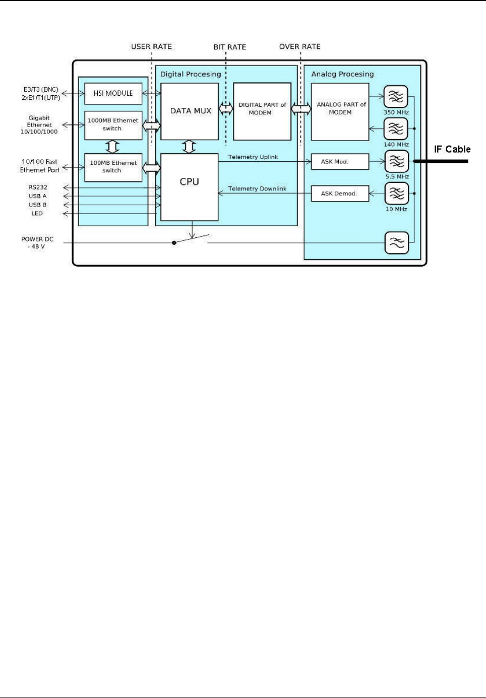
Appendix C - IDU Functionality
The following figure illustrates the functionality of an IDU.
The circuits of the Ethernet interface and the HSI module together with Digital Multiplexer (DATA
MUX), Digital Modem (DSP block), Central Processing Unit (CPU) and the Analog signal
processing block are the essential functional blocks of the IDU.
Data is first processed by the Ethernet physical layer, followed by the HSI interface. The
processed data is then directed to the Data Multiplexer for further processing. Digital modem
then adds synchronization marks, Forward Error Correction (FEC) to the data stream and creates
a digitally modulated signal, which is directed to the Analog signal block for further processing. All
these parts are interconnected inside the device with high-speed bus and are controlled by the
CPU. This block is also accessible via management interfaces and allows the user to configure
all the settings both locally and remotely through the IP interface on the IDU.
Digital Multiplexer (block DATA MUX), from a user's perspective is divided into two parts:
•RFI: Processes the data coming into the modem from HSI and Ethernet
•HSI: Process the data coming from the HSI module
RFI is a digital multiplexer (based on Packet Based Priority System (PBPS)) which creates a
single data stream for the modem block containing all the permitted user input data. The data
source for digital multiplexer are the signals from HSI interface, Ethernet data and data from the
internal BER tester. System PBPS first transmits the data with the high priority and than with the
low priority - from Ethernet block and from internal BER tester. Thus, prioritizing the data
transmission helps to dynamically reduce data transmission rate, depending on the available
overall transmission capacity.
Tsunami™ GX800 Installation and Management Guide 74
Figure 50: Block Diagram of the IDU
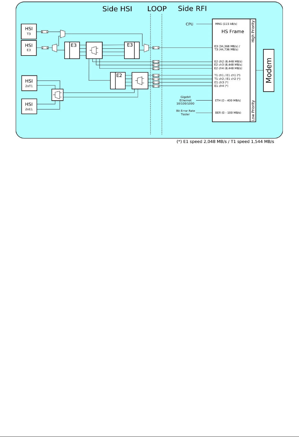
The priorities for data transmission are assigned in the following order:
1. Service monitoring channel signal for management - 115 kbps (the highest priority)
2. Signal E3/T3 from the Internal Bus – 34.368 / 44.736 Mbps
3. Signals E2 from the Internal Bus (channels 2 to 4) – 3 x 8.448 Mbps
4. Signals E1/T1 from the Internal Bus (channels 1 to 4 / 2) – 4 x 2,048 Mbps / 2 x 1,544
Mbps
5. Signal from Ethernet block – 0 up to 400 Mbps (400 for 56MHz)
6. Signal from BER tester – 1 up to 100 Mbps (the lowest priority )
DSP block is the core of the IDU and provides its own digital modulation and demodulation. The
whole block is configured and monitored by the CPU. All settings related to the types of
modulation and their selected bandwidth are loaded into the DSP block and this block ensures
the correct algorithm for data processing.
Tsunami™ GX800 Installation and Management Guide 75
Figure 51: Block Diagram of Data MUX

Appendix D – Abbreviation List
AGC Automatic Gain Control
AIS Alarm Indication Signal
ANEG Auto Negotiation
ATPC Automatic Power Control
ATU Table of MAC addresses
BER Bit Error Rate
BNC Bayonet Neill-Concelman
CPU Central Processing Unit
CRC Cyclic Redundancy Check
DC Direct Current
FEC Forward Error Correction
FER Frame Error Rate
HSI High Speed interface
IDU Indoor Unit
IF Intermediate Frequency
LAN Local Area Network
MSE Mean Square Error
NAT Network Address Translation
NMS Network Management System
ODU Outdoor Unit
PBPS Packet Based Priority System
PC Personal Computer
RFI Radio Frequency Interface
RSL Received Signal Level
RSSI Received Signal Strength Indication
SNMP Simple network management protocol
VLAN Virtual Local Area Network
Tsunami™ GX800 Installation and Management Guide 76
IMPORTANT NOTE:
FCC Radiation Exposure Statement:
This equipment complies with FCC radiation exposure limits set forth for an uncontrolled environment.
This equipment should be installed and operated with minimum distance 530cm between the radiator &
your body.