Proxim Wireless NGP1058B Point to Point and Point to Multipoint Outdoor Wireless Communication System User Manual AntennaInstallationGuide
Proxim Wireless Corporation Point to Point and Point to Multipoint Outdoor Wireless Communication System AntennaInstallationGuide
Contents
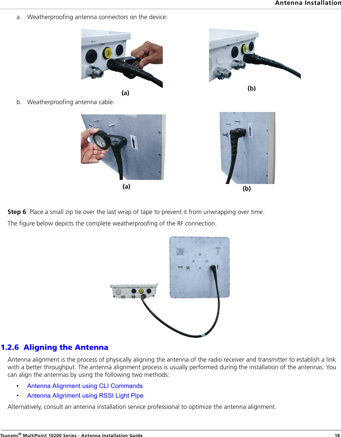
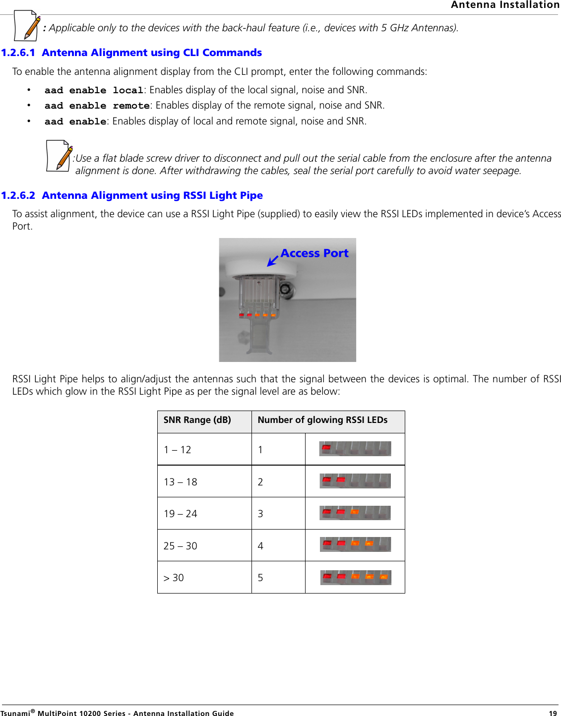
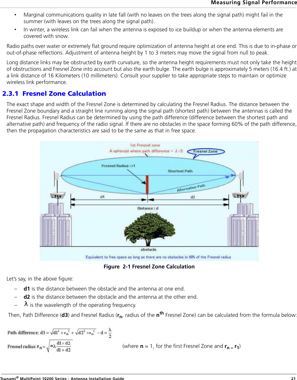
- 1. Professional Installation Guide
- 2. User Manual
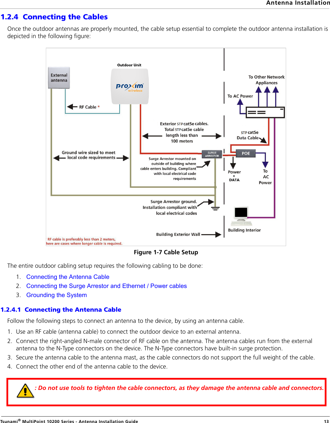
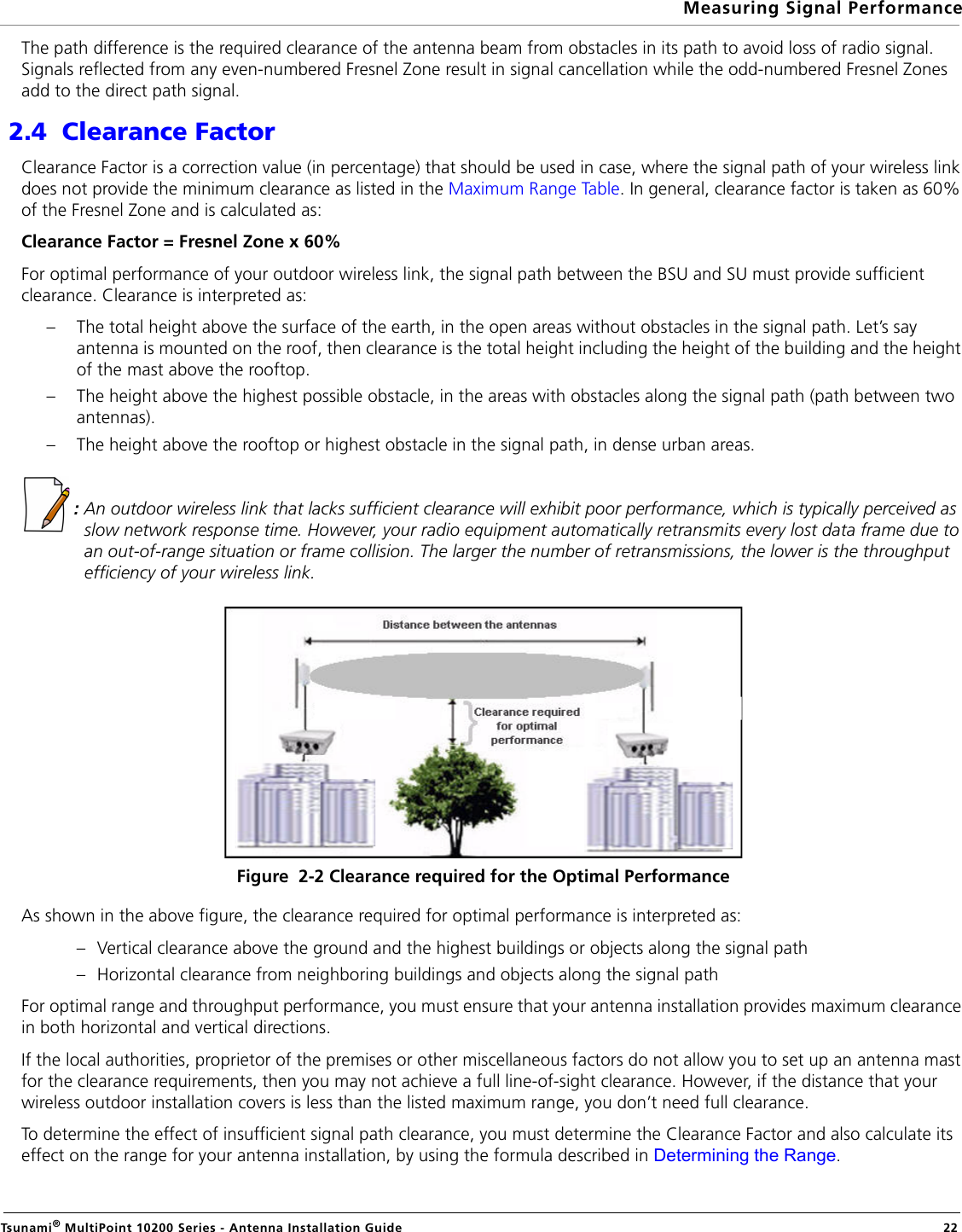
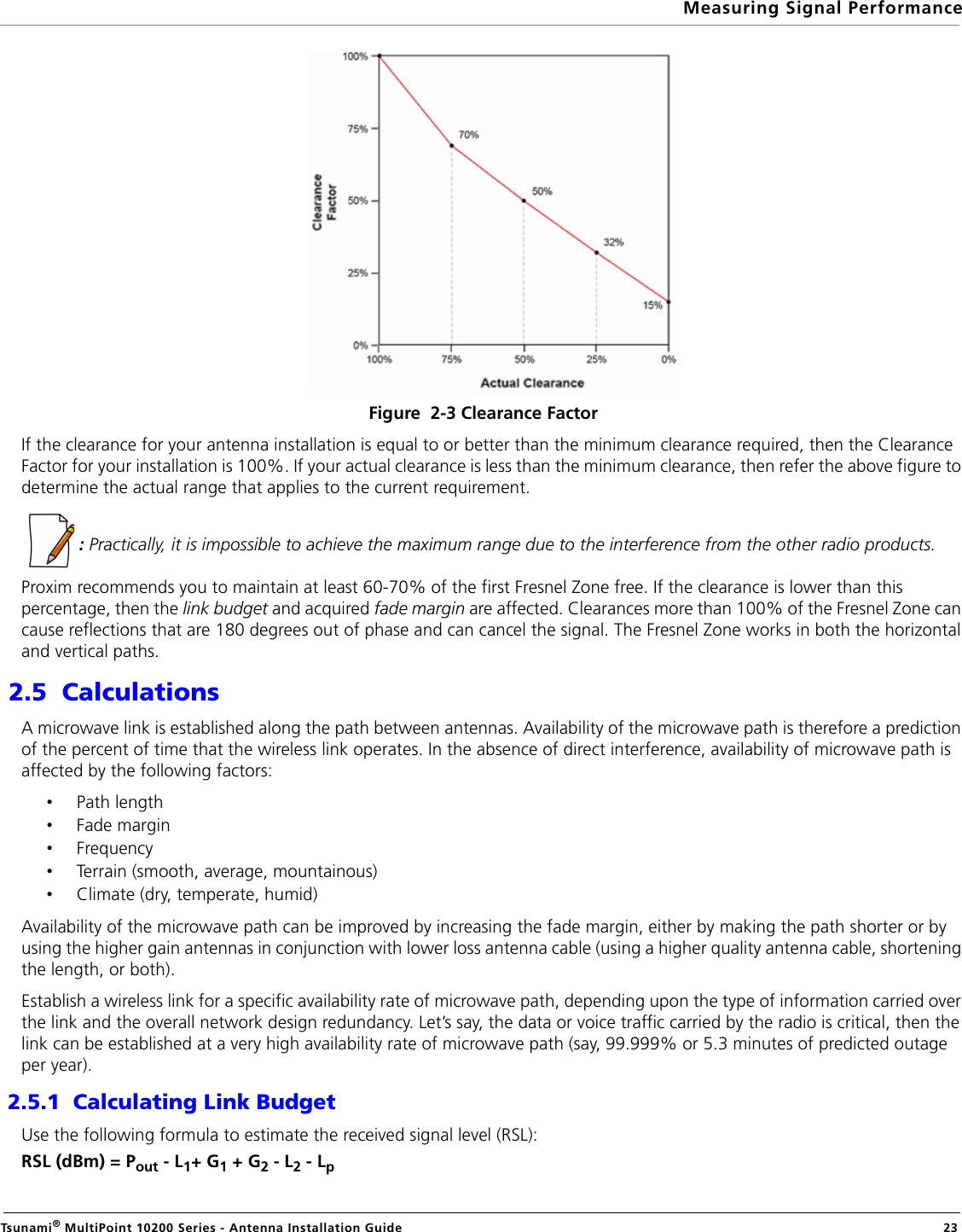
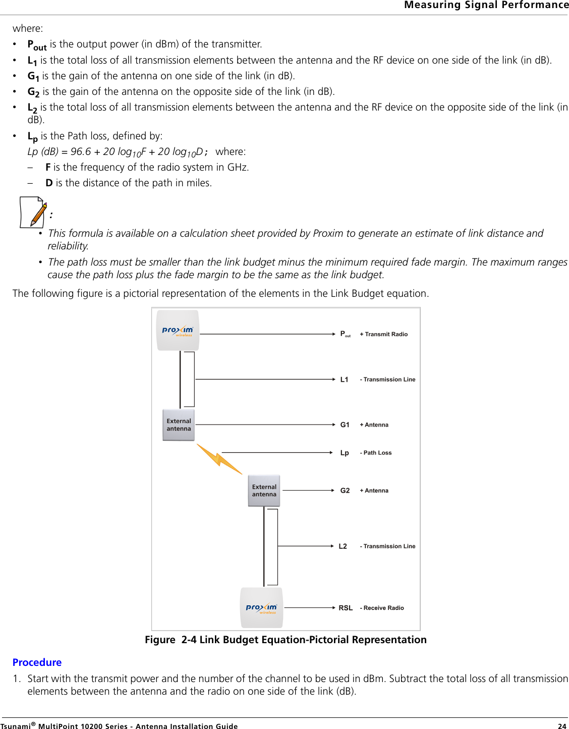
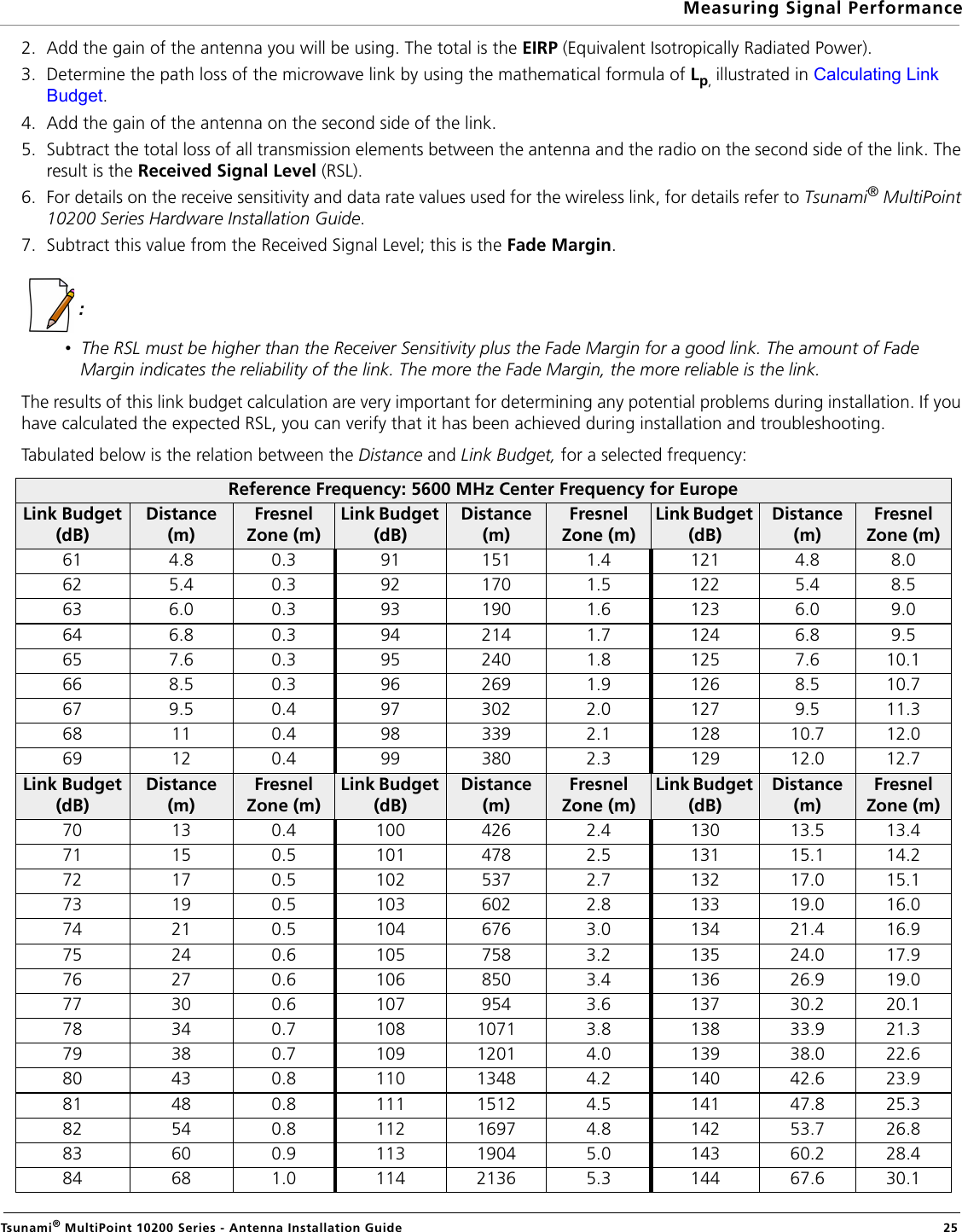
Professional Installation Guide