Proxim Wireless NGP1058B Point to Point and Point to Multipoint Outdoor Wireless Communication System User Manual Tsunami MP 10250 BSX QIG PrintCopy
Proxim Wireless Corporation Point to Point and Point to Multipoint Outdoor Wireless Communication System Tsunami MP 10250 BSX QIG PrintCopy
Contents
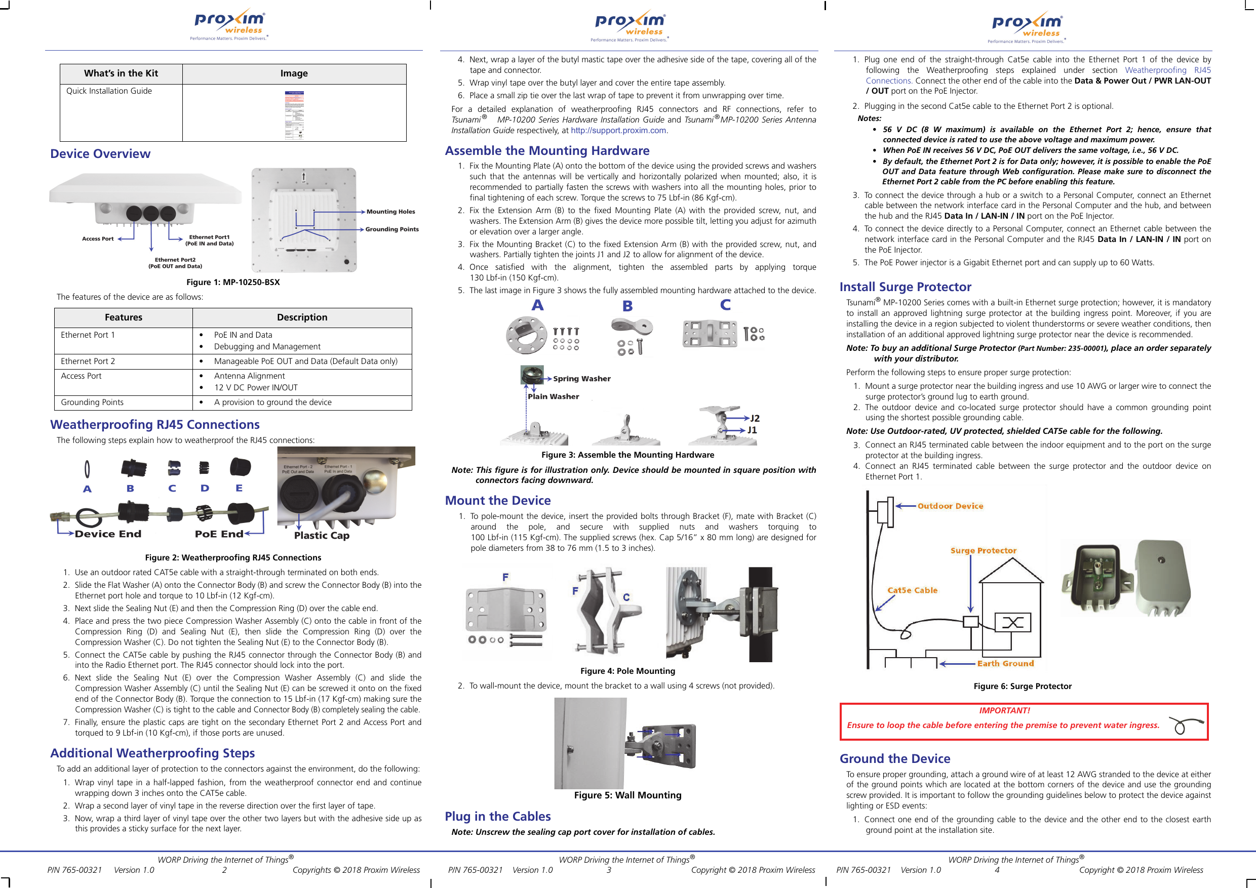
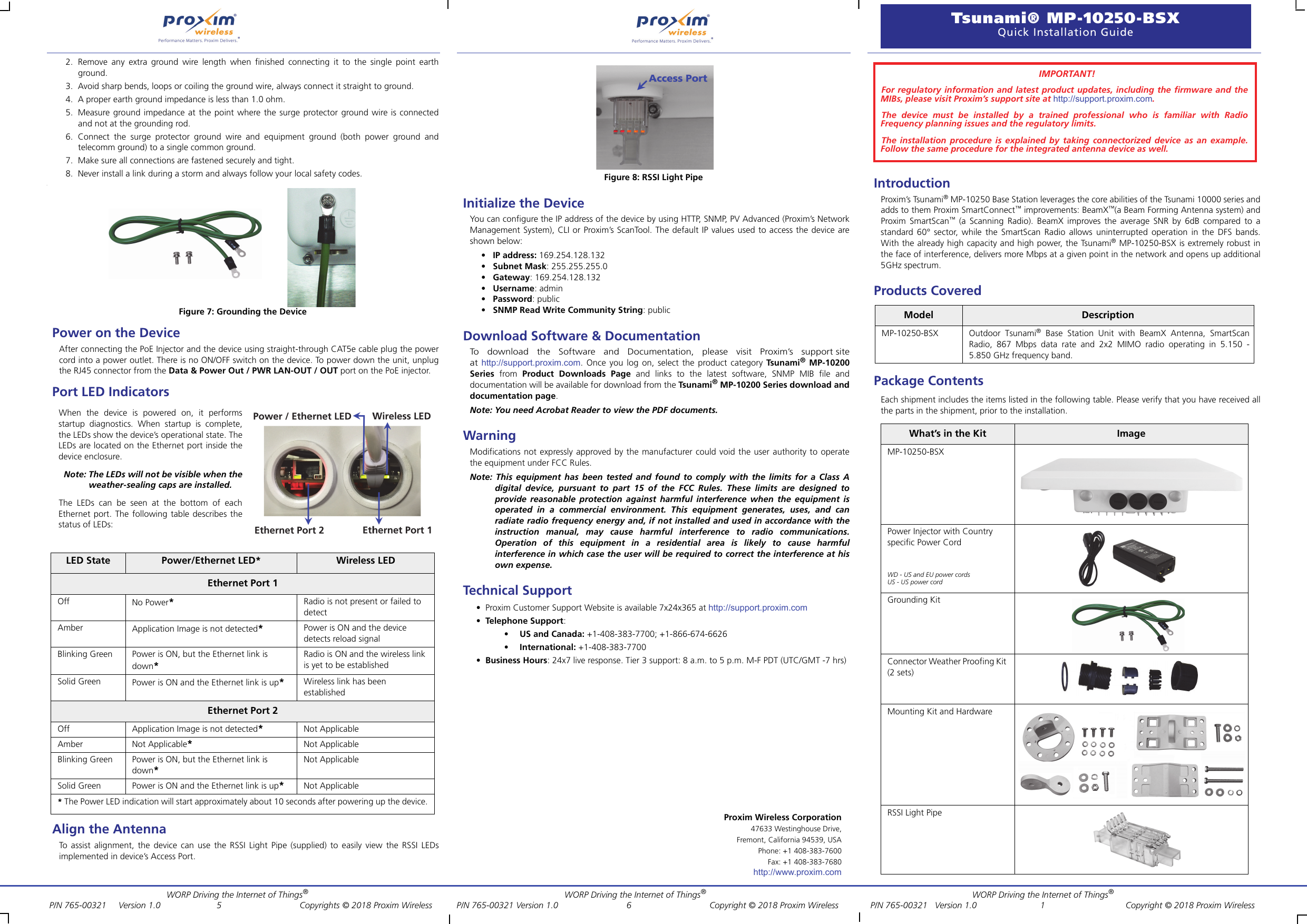
- 1. Professional Installation Guide
- 2. User Manual
User Manual