Proxim Wireless NGP1058B Point to Point and Point to Multipoint Outdoor Wireless Communication System User Manual Tsunami MP 10250 BSX QIG PrintCopy
Proxim Wireless Corporation Point to Point and Point to Multipoint Outdoor Wireless Communication System Tsunami MP 10250 BSX QIG PrintCopy
Contents
- 1. Professional Installation Guide
- 2. User Manual
User Manual
WORP Driving the Internet of Things® WORP Driving the Internet of Things® WORP Driving the Internet of Things®
P/N 765-00321 Version 1.0 2 Copyrights © 2018 Proxim Wireless P/N 765-00321 Version 1.0 3 Copyright © 2018 Proxim Wireless P/N 765-00321 Version 1.0 4 Copyright © 2018 Proxim Wireless
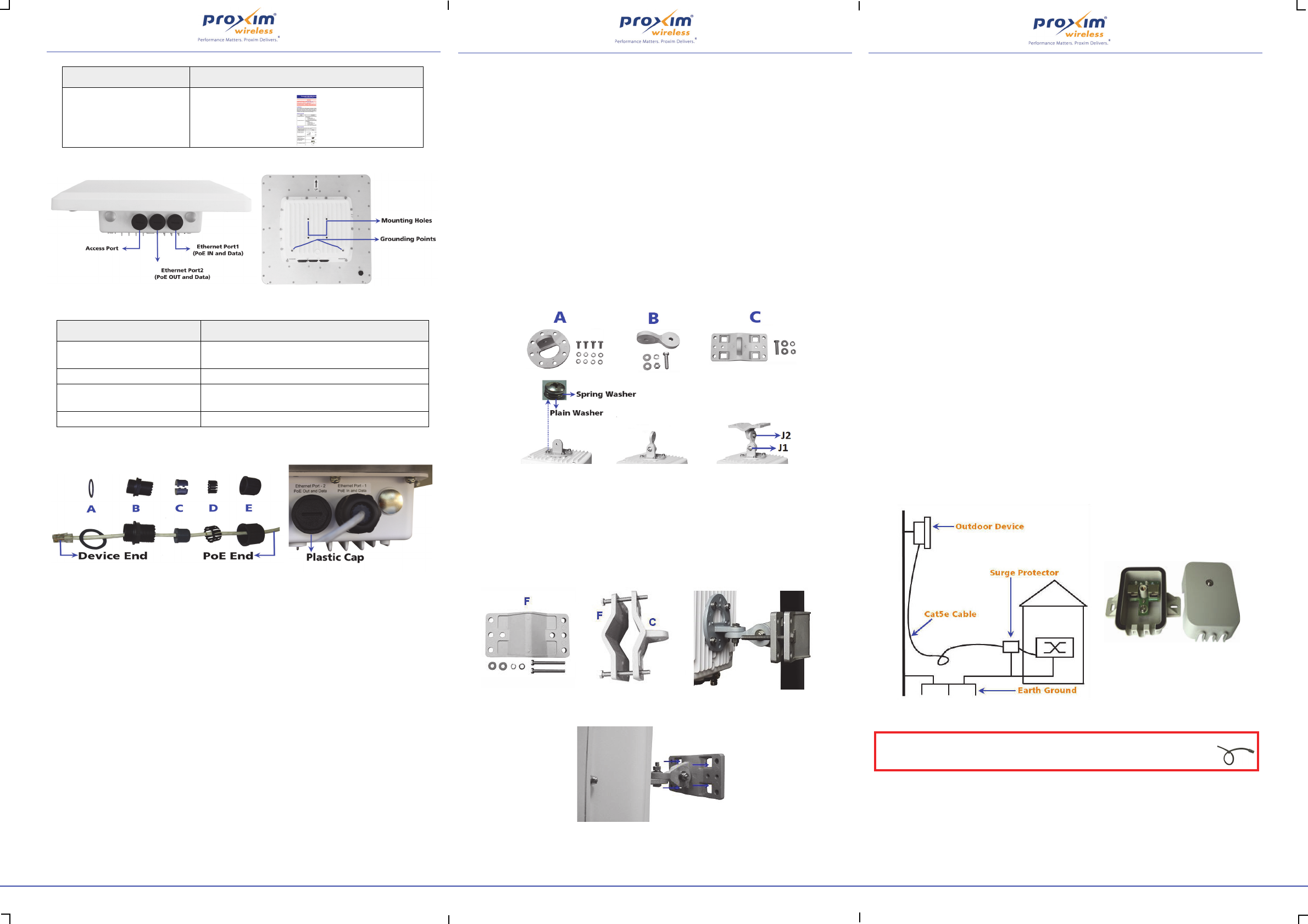
Device Overview
Figure 1: MP-10250-BSX
The features of the device are as follows:
Weatherproofing RJ45 Connections
The following steps explain how to weatherproof the RJ45 connections:
Figure 2: Weatherproofing RJ45 Connections
1. Use an outdoor rated CAT5e cable with a straight-through terminated on both ends.
2. Slide the Flat Washer (A) onto the Connector Body (B) and screw the Connector Body (B) into the
Ethernet port hole and torque to 10 Lbf-in (12 Kgf-cm).
3. Next slide the Sealing Nut (E) and then the Compression Ring (D) over the cable end.
4. Place and press the two piece Compression Washer Assembly (C) onto the cable in front of the
Compression Ring (D) and Sealing Nut (E), then slide the Compression Ring (D) over the
Compression Washer (C). Do not tighten the Sealing Nut (E) to the Connector Body (B).
5. Connect the CAT5e cable by pushing the RJ45 connector through the Connector Body (B) and
into the Radio Ethernet port. The RJ45 connector should lock into the port.
6. Next slide the Sealing Nut (E) over the Compression Washer Assembly (C) and slide the
Compression Washer Assembly (C) until the Sealing Nut (E) can be screwed it onto on the fixed
end of the Connector Body (B). Torque the connection to 15 Lbf-in (17 Kgf-cm) making sure the
Compression Washer (C) is tight to the cable and
Connector Body (B) completely sealing the cable.
7. Finally, ensure the plastic caps are tight on the secondary Ethernet Port 2 and Access Port and
torqued to 9 Lbf-in (10 Kgf-cm), if those ports are unused.
Additional Weatherproofing Steps
To add an additional layer of protection to the connectors against the environment, do the following:
1. Wrap vinyl tape in a half-lapped fashion, from the weatherproof connector end and continue
wrapping down 3 inches onto the CAT5e cable.
2. Wrap a second layer of vinyl tape in the reverse direction over the first layer of tape.
3. Now, wrap a third layer of vinyl tape over the other two layers but with the adhesive side up as
this provides a sticky surface for the next layer.
4. Next, wrap a layer of the butyl mastic tape over the adhesive side of the tape, covering all of the
tape and connector.
5. Wrap vinyl tape over the butyl layer and cover the entire tape assembly.
6. Place a small zip tie over the last wrap of tape to prevent it from unwrapping over time.
For a detailed explanation of weatherproofing RJ45 connectors and RF connections, refer to
Tsunami ® MP-10200 Series Hardware Installation Guide and Tsunami ®MP-10200 Series Antenna
Installation Guide respectively, at http://support.proxim.com.
Assemble the Mounting Hardware
1. Fix the Mounting Plate (A) onto the bottom of the device using the provided screws and washers
such that the antennas will be vertically and horizontally polarized when mounted; also, it is
recommended to partially fasten the screws with washers into all the mounting holes, prior to
final tightening of each screw. Torque the screws to 75 Lbf-in (86 Kgf-cm).
2. Fix the Extension Arm (B) to the fixed Mounting Plate (A) with the provided screw, nut, and
washers. The Extension Arm (B) gives the device more possible tilt, letting you adjust for azimuth
or elevation over a larger angle.
3. Fix the Mounting Bracket (C) to the fixed Extension Arm (B) with the provided screw, nut, and
washers. Partially tighten the joints J1 and J2 to allow for alignment of the device.
4. Once satisfied with the alignment, tighten the assembled parts by applying torque
130 Lbf-in (150 Kgf-cm).
5. The last image in Figure 3 shows the fully assembled mounting hardware attached to the device.
Figure 3: Assemble the Mounting Hardware
Note: This figure is for illustration only. Device should be mounted in square position with
connectors facing downward.
Mount the Device
1. To pole-mount the device, insert the provided bolts through Bracket (F), mate with Bracket (C)
around the pole, and secure with supplied nuts and washers torquing to
100 Lbf-in (115 Kgf-cm). The supplied screws (hex. Cap 5/16” x 80 mm long) are designed for
pole diameters from 38 to 76 mm (1.5 to 3 inches).
Figure 4: Pole Mounting
2. To wall-mount the device, mount the bracket to a wall using 4 screws (not provided).
Figure 5: Wall Mounting
Plug in the Cables
Note: Unscrew the sealing cap port cover for installation of cables.
1. Plug one end of the straight-through Cat5e cable into the Ethernet Port 1 of the device by
following the Weatherproofing steps explained under section Weatherproofing RJ45
Connections. Connect the other end of the cable into the Data & Power Out / PWR LAN-OUT
/ OUT port on the PoE Injector.
2. Plugging in the second Cat5e cable to the Ethernet Port 2 is optional.
Notes:
• 56 V DC (8 W maximum) is available on the Ethernet Port 2; hence, ensure that
connected device is rated to use the above voltage and maximum power.
• When PoE IN receives 56 V DC, PoE OUT delivers the same voltage, i.e., 56 V DC.
• By default, the Ethernet Port 2 is for Data only; however, it is possible to enable the PoE
OUT and Data feature through Web configuration. Please make sure to disconnect the
Ethernet Port 2 cable from the PC before enabling this feature.
3. To connect the device through a hub or a switch to a Personal Computer, connect an Ethernet
cable between the network interface card in the Personal Computer and the hub, and between
the hub and the RJ45 Data In / LAN-IN / IN port on the PoE Injector.
4. To connect the device directly to a Personal Computer, connect an Ethernet cable between the
network interface card in the Personal Computer and the RJ45 Data In / LAN-IN / IN port on
the PoE Injector.
5. The PoE Power injector is a Gigabit Ethernet port and can supply up to 60 Watts.
Install Surge Protector
Tsu na mi ® MP-10200 Series comes with a built-in Ethernet surge protection; however, it is mandatory
to install an approved lightning surge protector at the building ingress point. Moreover, if you are
installing the device in a region subjected to violent thunderstorms or severe weather conditions, then
installation of an additional approved lightning surge protector near the device is recommended.
Note: To buy an additional Surge Protector (Part Number: 235-00001), place an order separately
with your distributor.
Perform the following steps to ensure proper surge protection:
1. Mount a surge protector near the building ingress and use 10 AWG or larger wire to connect the
surge protector’s ground lug to earth ground.
2. The outdoor device and co-located surge protector should have a common grounding point
using the shortest possible grounding cable.
Note: Use Outdoor-rated, UV protected, shielded CAT5e cable for the following.
3. Connect an RJ45 terminated cable between the indoor equipment and to the port on the surge
protector at the building ingress.
4. Connect an RJ45 terminated cable between the surge protector and the outdoor device on
Ethernet Port 1.
Figure 6: Surge Protector
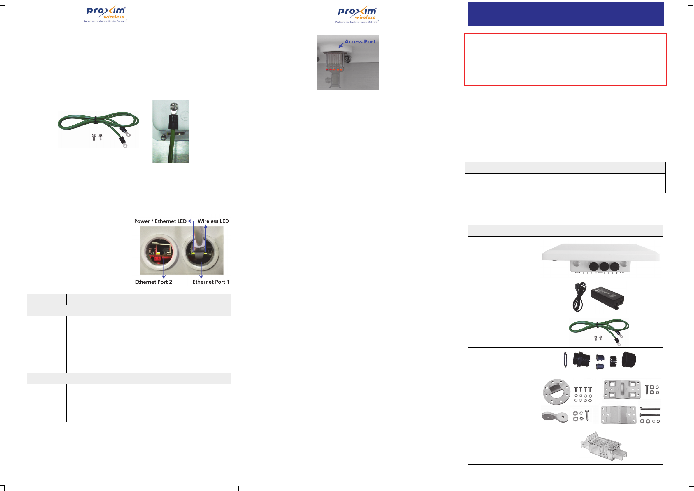
Ground the Device
To ensure proper grounding, attach a ground wire of at least 12 AWG stranded to the device at either
of the ground points which are located at the bottom corners of the device and use the grounding
screw provided. It is important to follow the grounding guidelines below to protect the device against
lighting or ESD events:
1. Connect one end of the grounding cable to the device and the other end to the closest earth
ground point at the installation site.
What’s in the Kit Image
Quick Installation Guide
Features Description
Ethernet Port 1 • PoE IN and Data
• Debugging and Management
Ethernet Port 2 • Manageable PoE OUT and Data (Default Data only)
Access Port • Antenna Alignment
• 12 V DC Power IN/OUT
Grounding Points • A provision to ground the device
IMPORTANT!
Ensure to loop the cable before entering the premise to prevent water ingress.
WORP Driving the Internet of Things® WORP Driving the Internet of Things® WORP Driving the Internet of Things®
P/N 765-00321 Version 1.0 5 Copyrights © 2018 Proxim Wireless P/N 765-00321 Version 1.0 6 Copyright © 2018 Proxim Wireless P/N 765-00321 Version 1.0 1 Copyright © 2018 Proxim Wireless
Proxim Wireless Corporation
47633 Westinghouse Drive,
Fremont, California 94539, USA
Phone: +1 408-383-7600
Fax: +1 408-383-7680
http://www.proxim.com
Tsunami® MP-10250-BSX
Quick Installation Guide
2. Remove any extra ground wire length when finished connecting it to the single point earth
ground.
3. Avoid sharp bends, loops or coiling the ground wire, always connect it straight to ground.
4. A proper earth ground impedance is less than 1.0 ohm.
5. Measure ground impedance at the point where the surge protector ground wire is connected
and not at the grounding rod.
6. Connect the surge protector ground wire and equipment ground (both power ground and
telecomm ground) to a single common ground.
7. Make sure all connections are fastened securely and tight.
8. Never install a link during a storm and always follow your local safety codes.
.
Figure 7: Grounding the Device
Power on the Device
After connecting the PoE Injector and the device using straight-through CAT5e cable plug the power
cord into a power outlet. There is no ON/OFF switch on the device. To power down the unit, unplug
the RJ45 connector from the Data & Power Out / PWR LAN-OUT / OUT port on the PoE injector.
Port LED Indicators
Align the Antenna
To assist alignment, the device can use the RSSI Light Pipe (supplied) to easily view the RSSI LEDs
implemented in device’s Access Port.
Figure 8: RSSI Light Pipe
Initialize the Device
You can configure the IP address of the device by using HTTP, SNMP, PV Advanced (Proxim’s Network
Management System), CLI or Proxim’s ScanTool. The default IP values used to access the device are
shown below:
• IP address: 169.254.128.132
•Subnet Mask: 255.255.255.0
•Gateway: 169.254.128.132
•Username: admin
•Password: public
•SNMP Read Write Community String: public
Download Software & Documentation
To download the Software and Documentation, please visit Proxim’s support site
at
http://support.proxim.com. Once you log on, select the product category Tsun am i® MP-10200
Series from Product Downloads Page and links to the latest software, SNMP MIB file and
documentation will be available for download from the Tsu na m i® MP-10200 Series download and
documentation page.
Note: You need Acrobat Reader to view the PDF documents.
Warning
Modifications not expressly approved by the manufacturer could void the user authority to operate
the equipment under FCC Rules.
Note: This equipment has been tested and found to comply with the limits for a Class A
digital device, pursuant to part 15 of the FCC Rules. These limits are designed to
provide reasonable protection against harmful interference when the equipment is
operated in a commercial environment. This equipment generates, uses, and can
radiate radio frequency energy and, if not installed and used in accordance with the
instruction manual, may cause harmful interference to radio communications.
Operation of this equipment in a residential area is likely to cause harmful
interference in which case the user will be required to correct the interference at his
own expense.
Technical Support
• Proxim Customer Support Website is available 7x24x365 at http://support.proxim.com
•Telephone Support:
•US and Canada: +1-408-383-7700; +1-866-674-6626
•International: +1-408-383-7700
•Business Hours: 24x7 live response. Tier 3 support: 8 a.m. to 5 p.m. M-F PDT (UTC/GMT -7 hrs)
Introduction
Proxim’s Tsunami® MP-10250 Base Station leverages the core abilities of the Tsunami 10000 series and
adds to them Proxim SmartConnect™ improvements: BeamX™(a Beam Forming Antenna system) and
Proxim SmartScan™ (a Scanning Radio). BeamX improves the average SNR by 6dB compared to a
standard 60° sector, while the SmartScan Radio allows uninterrupted operation in the DFS bands.
With the already high capacity and high power, the Tsunami® MP-10250-BSX is extremely robust in
the face of interference, delivers more Mbps at a given point in the network and opens up additional
5GHz spectrum.
Products Covered
Package Contents
Each shipment includes the items listed in the following table. Please verify that you have received all
the parts in the shipment, prior to the installation.
LED State Power/Ethernet LED* Wireless LED
Ethernet Port 1
Off No Power*Radio is not present or failed to
detect
Amber Application Image is not detected*Power is ON and the device
detects reload signal
Blinking Green Power is ON, but the Ethernet link is
down*
Radio is ON and the wireless link
is yet to be established
Solid Green Power is ON and the Ethernet link is up*Wireless link has been
established
Ethernet Port 2
Off Application Image is not detected*Not Applicable
Amber Not Applicable*Not Applicable
Blinking Green Power is ON, but the Ethernet link is
down*
Not Applicable
Solid Green Power is ON and the Ethernet link is up*Not Applicable
* The Power LED indication will start approximately about 10 seconds after powering up the device.
When the device is powered on, it performs
startup diagnostics. When startup is complete,
the LEDs show the device’s operational state. The
LEDs are located on the Ethernet port inside the
device enclosure.
Note: The LEDs will not be visible when the
weather-sealing caps are installed.
The LEDs can be seen at the bottom of each
Ethernet port. The following table describes the
status of LEDs:
Model Description
MP-10250-BSX Outdoor Tsunami® Base Station Unit with BeamX Antenna, SmartScan
Radio, 867 Mbps data rate and 2x2 MIMO radio operating in 5.150 -
5.850 GHz frequency band.
What’s in the Kit Image
MP-10250-BSX
Power Injector with Country
specific Power Cord
WD - US and EU power cords
US - US power cord
Grounding Kit
Connector Weather Proofing Kit
(2 sets)
Mounting Kit and Hardware
RSSI Light Pipe
IMPORTANT!
For regulatory information and latest product updates, including the firmware and the
MIBs, please visit Proxim’s support site at http://support.proxim.com.
The device must be installed by a trained professional who is familiar with Radio
Frequency planning issues and the regulatory limits.
The installation procedure is explained by taking connectorized device as an example.
Follow the same procedure for the integrated antenna device as well.