Proxim Wireless PROXMB82 802.11A/B/G/N MPCI MODULE User Manual Hardware Installation Guide
Proxim Wireless Corporation 802.11A/B/G/N MPCI MODULE Hardware Installation Guide
Contents
- 1. User Manual
- 2. users manual-1
- 3. users manual-2
- 4. Software guide1
- 5. software guide2
users manual-2
8000 Series - Hardware Overview and Installation
Tsunami® 800 and 8000 Series - Hardware Installation Guide 81
3.4 MP-8160-CPE-A100
This section provides the hardware overview and installation method for MP-8160-CPE.
3.4.1 Hardware Overview
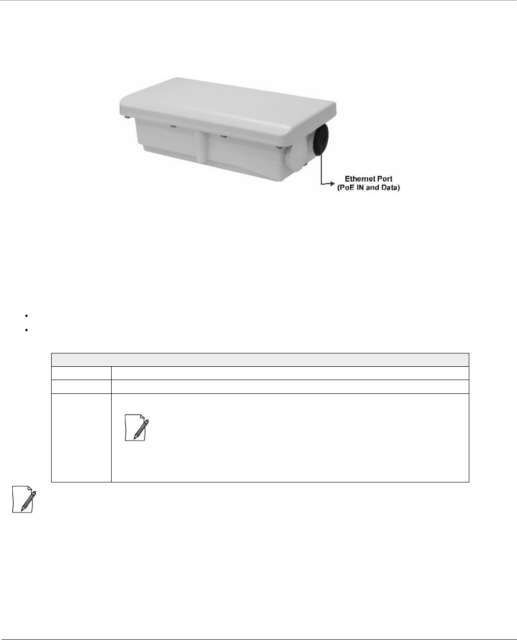
Figure 3-34 MP-8160-CPE
A detailed description about the various components of the device are explained in the following sections.
3.4.1.1 Ethernet Port (PoE IN and Data)
The device comes with auto-sensing 10/100 BASE-T Ethernet port with configurable Tx Modes and Speeds.
The Ethernet port of the device allows the user to connect to the LAN by using Cat5/Cat5e or better Ethernet cable, and also
power ON the device by using the Power over Ethernet (PoE) Injector supplied with the product package.
The device receives 48 VDC via a standard Cat5/Cat5e or better cable connected to the Ethernet port.
Maximum power supplied to the device is 19.2 Watts. The device typically draws 5 Watts.
: Always use a straight cable from PoE to the device. When you use a 4-pair cross over ethernet cable, the reload
functionality gets activated and forcibly deletes the operating image.
3.4.1.2 Grounding Point
To protect the device against lighting or ESD events, you must ground the device properly. To ensure proper grounding, use
the grounding point situated at the bottom corner of the device and the grounding screw (M4 thread size) provided to attach
a ground wire of at least 12 AWG stranded to the device.
Recommended Ethernet Cable Specifications
Type Cat5/5e or better, STP, 24 AWG, UL rated, UV-shielded and outdoor-rated
Impedance 100 ohms
Cable Length 330 feet / 100 meters
: The total length of cabling between the Personal Computer and the device
cannot exceed 100 meters (includes cable from the Personal Computer to
the PoE, and the cable from the PoE to the device. Due to DC power
requirements, the maximum cable length between the PoE Injector and the
device is 75 meters.
8000 Series - Hardware Overview and Installation
Tsunami® 800 and 8000 Series - Hardware Installation Guide 82
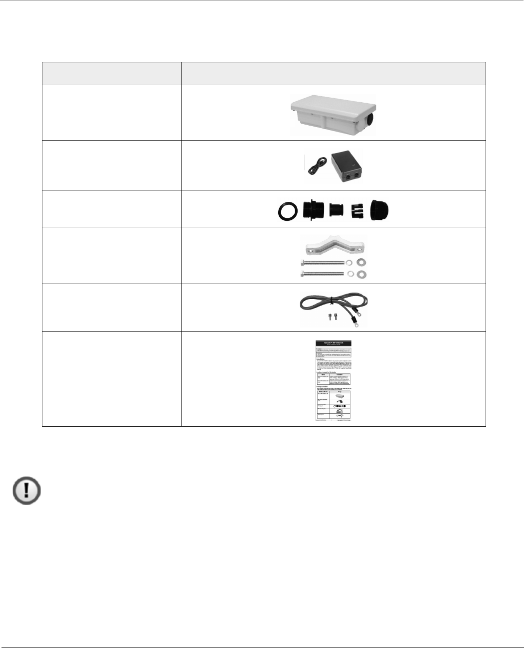
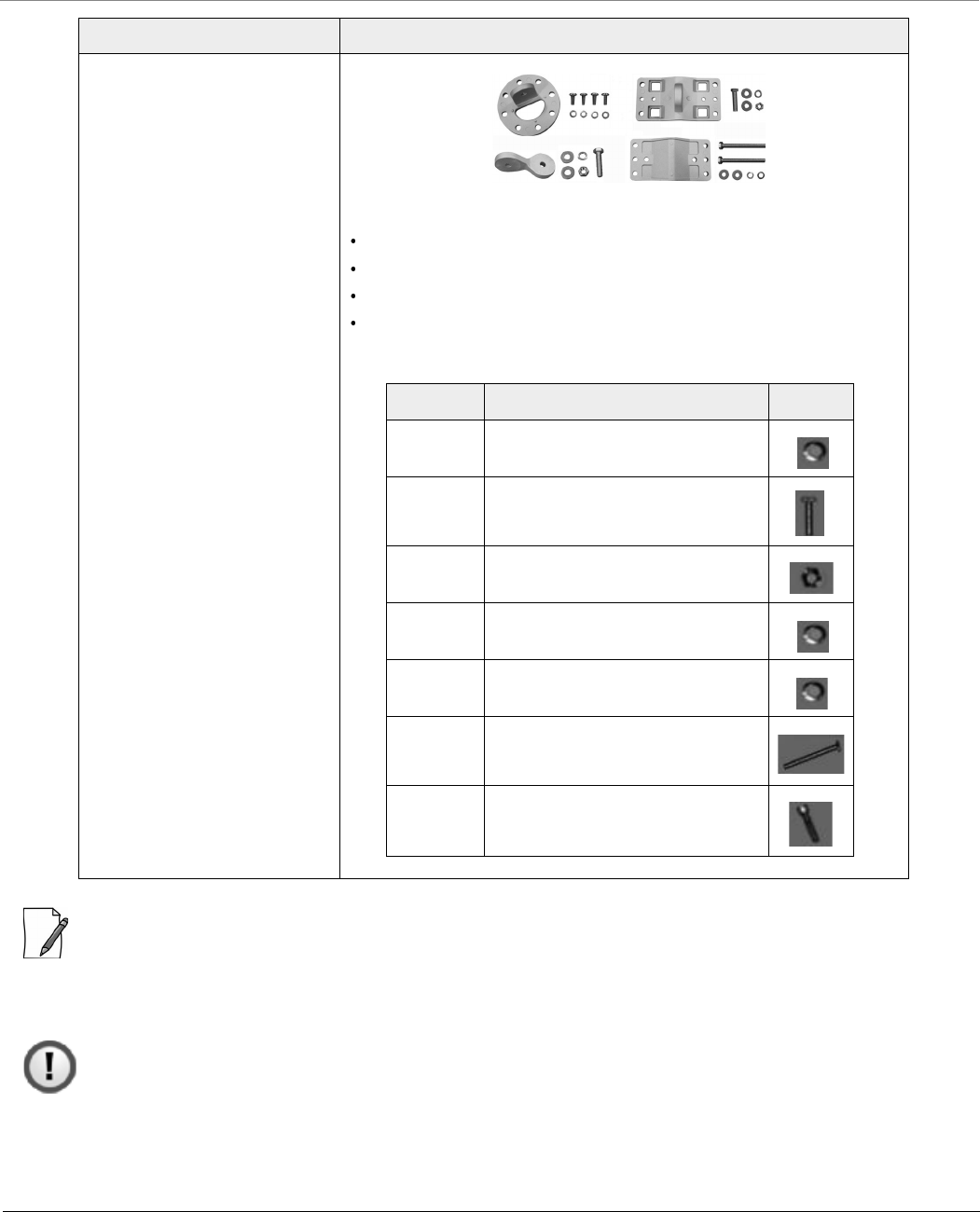
3.4.2 Product Package
Each shipment includes the items listed in the following table. Please verify that you have received all the parts in the
shipment prior to installation.
3.4.3 Installation Procedure
This section describes the steps to install and mount the device.
: The device must be installed by a trained professional who is familiar with radio frequency planning and
regulatory limits.
Perform the following steps to install and mount the device.
Step 1: Plan for Installation
There are several planning factors to be considered before installing the device. In addition to selecting the installation site,
you should do the following:
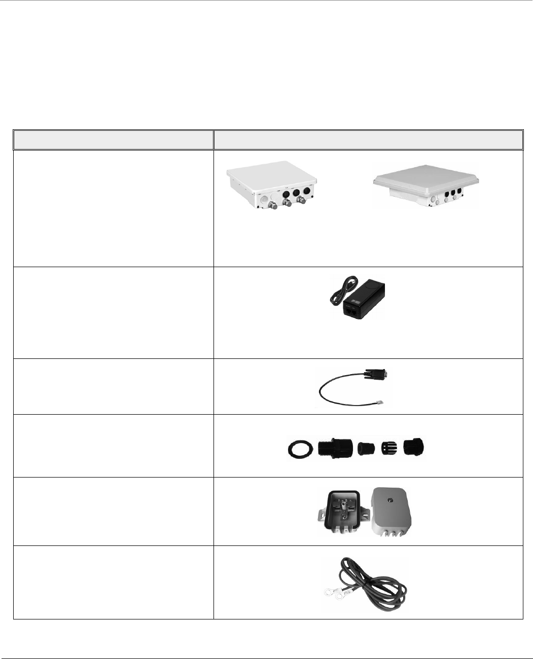
What’s in the Kit Image
MP-8160-CPE
PoE Injector and Power Cord
WD - EU power cord
Connector Weather Proofing
Kit
Pole Mounting Kit
Grounding Kit
Quick Installation Guide

8000 Series - Hardware Overview and Installation
Tsunami® 800 and 8000 Series - Hardware Installation Guide 83
Calculate:
Required RSL and fade margin to achieve link availability objectives. For more details on how to calculate RSL and fade
margin, please refer to the ‘Antenna Installation Guide’ and ‘Proxim Link Calculator’ that are available on the support
site at .
Required path availability
Anticipated multi-path reflection points
Determine:
System Frequency Plan
Required transmission line types (like cable, waveguides) and lengths
Plan for:
Device’s continuous power consumption needs
Lightning protection and system grounding
Hardware mounting
Cable installation including egress
Pre-testing equipment (back-to-back test procedure)
Step 2: Choose a Location
To make optimal use of the device, you must find a suitable location to install the hardware. Proxim recommends you do a site
survey, observing the following requirements, before mounting the hardware.
The location must allow easy disconnection of power to the radio, if necessary.
Ensure free flow of air around the hardware.
The radio device must be kept away from vibration and excessive heat.
The installation must conform to local regulations at all times.
Step 3: Gather Required Tools
You should have the following tools available before installing the device:
Cross-tip screwdrivers
Large blade standard screwdriver
Spanner 13
Wire crimpers (if using connectors that are not pre-made)
Step 4: Unpack the Product Package
Unpack the device and its accessories from the shipping box.
Please make a note of the Ethernet addresses, MAC addresses and the serial number. These addresses may be used
when configuring the device. Note that the serial number helps you to seek support from the Proxim’s Customer
support team.
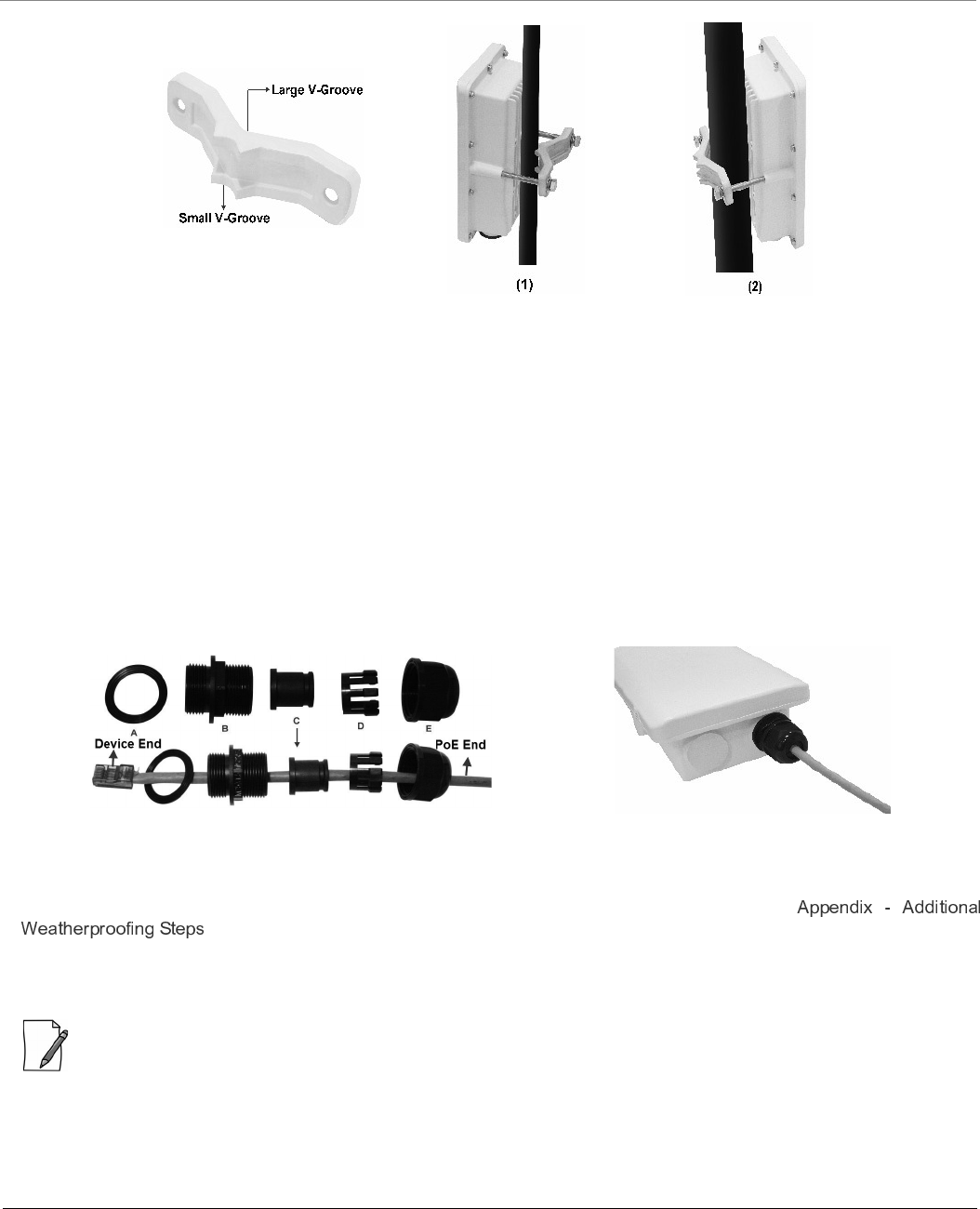
Step 5: Pole Mount the Device
1. To pole-mount the device to a 1 inch diameter pole, place the mounting bracket with its small V-Groove facing the
pole.
2. To pole-mount the device to a 2.5 inch diameter pole, place the mounting bracket with its large V-Groove facing the
pole.
3. Place the device with its rear side facing the pole, and screw the M8x80mm long screws along with the spring and
plain washers through the mounting bracket into the mounting holes of the device and tighten it to torque of 11
N.m/100 in-lbs.
8000 Series - Hardware Overview and Installation
Tsunami® 800 and 8000 Series - Hardware Installation Guide 84
Figure 3-35 Pole-Mounting
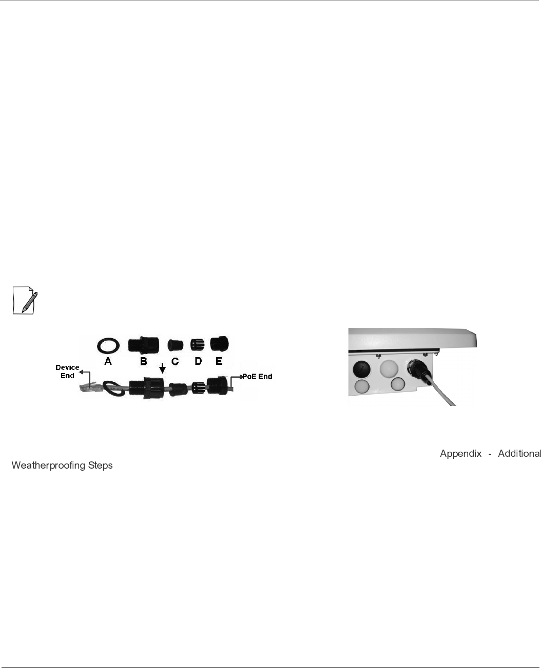
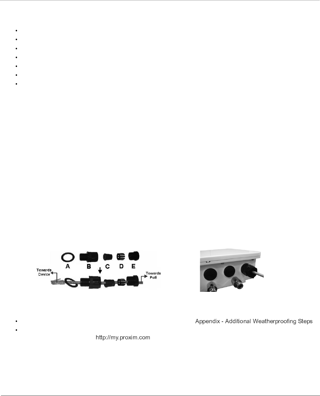
Step 6: Weatherproof RJ45 Connectors
The following steps explain how to weatherproof the RJ45 connector:
1. Use a straight-through cable (Cat5/5e or better) with one end bare.
2. Connect the crimped RJ45 connector end of the cable into the RJ45 Ethernet port inside the enclosure. The cable
connector should latch into the Ethernet port.
3. Slide the Flat Washer (A) into the Connector Body (B) to make it waterproof and onto the bare end of the cable. Next,
fasten the Connector Body into the Ethernet connector hole on the device.
4. Slide the tube-shaped Compression Washer (C) into the Compression Ring (D) and onto the cable from the bare end,
and insert into the fixed Connector Body.
5. Slide the Sealing Nut (E) over the bare end of the cable and fasten it on the fixed Connector Body.
6. Crimp the bare end of the cable with RJ45 connector and connect it to the LAN+DC port on the PoE Injector.
Figure 3-36 Weatherproofing RJ45 Connectors
Additional Weatherproofing Steps
To add an additional layer of protection to the connectors against the environment, see
.
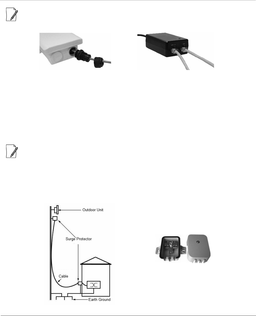
Step 7: Plug in the Cables
: Unscrew the sealing cap for installation of the cable.
1. Plug one end of the Cat5/5e cable into the Ethernet port of the device by following the Weatherproofing steps as
explained in Step 5. Connect the other end of the Cat5/5e or better cable to the LAN +DC port on the PoE Injector.
8000 Series - Hardware Overview and Installation
Tsunami® 800 and 8000 Series - Hardware Installation Guide 85
: Always use a straight cable from PoE to the device. When you use a 4-pair cross over ethernet cable, the reload
functionality gets activated and forcibly deletes the operating image.
Figure 3-37 Cables Plugged In
2. To connect the device through a hub or a switch to a Personal Computer, connect an Ethernet cable between the
network interface card in the Personal Computer and the hub/switch, and between the hub/switch and the RJ45 LAN
port on the PoE Injector.
3. To connect the device directly to a Personal Computer, connect an Ethernet cable between the network interface
card in the Personal Computer and the RJ45 LAN port on the PoE Injector.
Step 8: Install Surge Protector
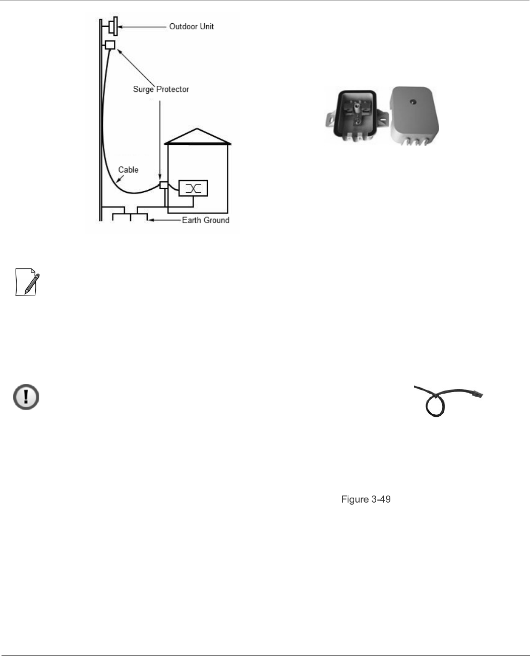
Proxim recommends two approved lightning surge protectors to be installed, one near to the device and the other at the
building ingress point.
: To buy a suitable Surge Protector, place an order separately with your distributor.
Perform the following steps to ensure proper surge protection:
1. Mount the surge protector near the outdoor device and use 10 AWG or larger wire to connect the protector’s ground
lug to the appropriate mounting ground point. The outdoor device and co-located surge protector should have a
common grounding point using the shortest possible grounding cable.
2. Mount a second surge protector near the building ingress and use 10 AWG or larger wire to connect the surge
protector’s ground lug to earth ground as shown in the following figure.
Figure 3-38 Surge Protector
8000 Series - Hardware Overview and Installation
Tsunami® 800 and 8000 Series - Hardware Installation Guide 86
: Use Outdoor-rated, UV protected, shielded Cat5/Cat5e cable for the following.
3. Connect an RJ45 terminated cable between the indoor equipment and to the port on the surge protector at the
building ingress.
4. Connect a short RJ45 terminated cable between the outdoor equipment and the port on the co-located surge
protector.
5. Connect an RJ45 terminated cable between the two surge protectors on their remaining ports.
: Ensure to loop the cable before entering the premise to prevent water ingress.
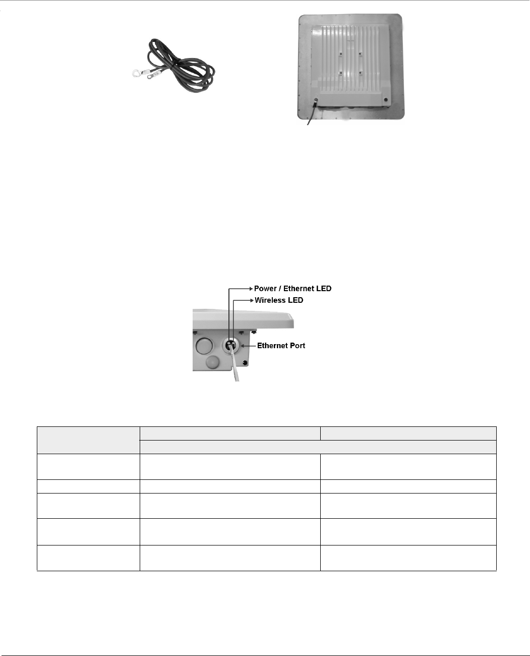
Step 9: Ground the Device
To ensure proper grounding, use the grounding point situated at the bottom corner of the device and the grounding screw
provided to attach a ground wire of at least 12 AWG stranded to the device. It is important that the following grounding
guidelines are followed to protect the device against lighting or ESD events:
1. Connect one end of the grounding cable to the device and the other end to the closest earthing system point at the
installation.
2. Cut any extra ground wire length when finished connecting it to the single point earth ground.
3. Avoid sharp bends and never loop or coil up the ground wire, always connect it straight to ground.
4. A good earth ground impedance is less than 1.0 ohm.
5. Make sure all connections are fastened securely and are tight.
6. Never install during a storm and always follow your local safety codes.
Connect the grounding wire, which is supplied with the product package, to the grounding lug:
Figure 3-39 Ground the Device
Step 10: Power ON the Device
Plug in the power cord into a power outlet after having connected the PoE Injector and the device using Cat5/5e cable. There
is no ON/OFF switch on the device. To disconnect power, unplug the RJ45 connector from the LAN+DC port on the PoE
injector.
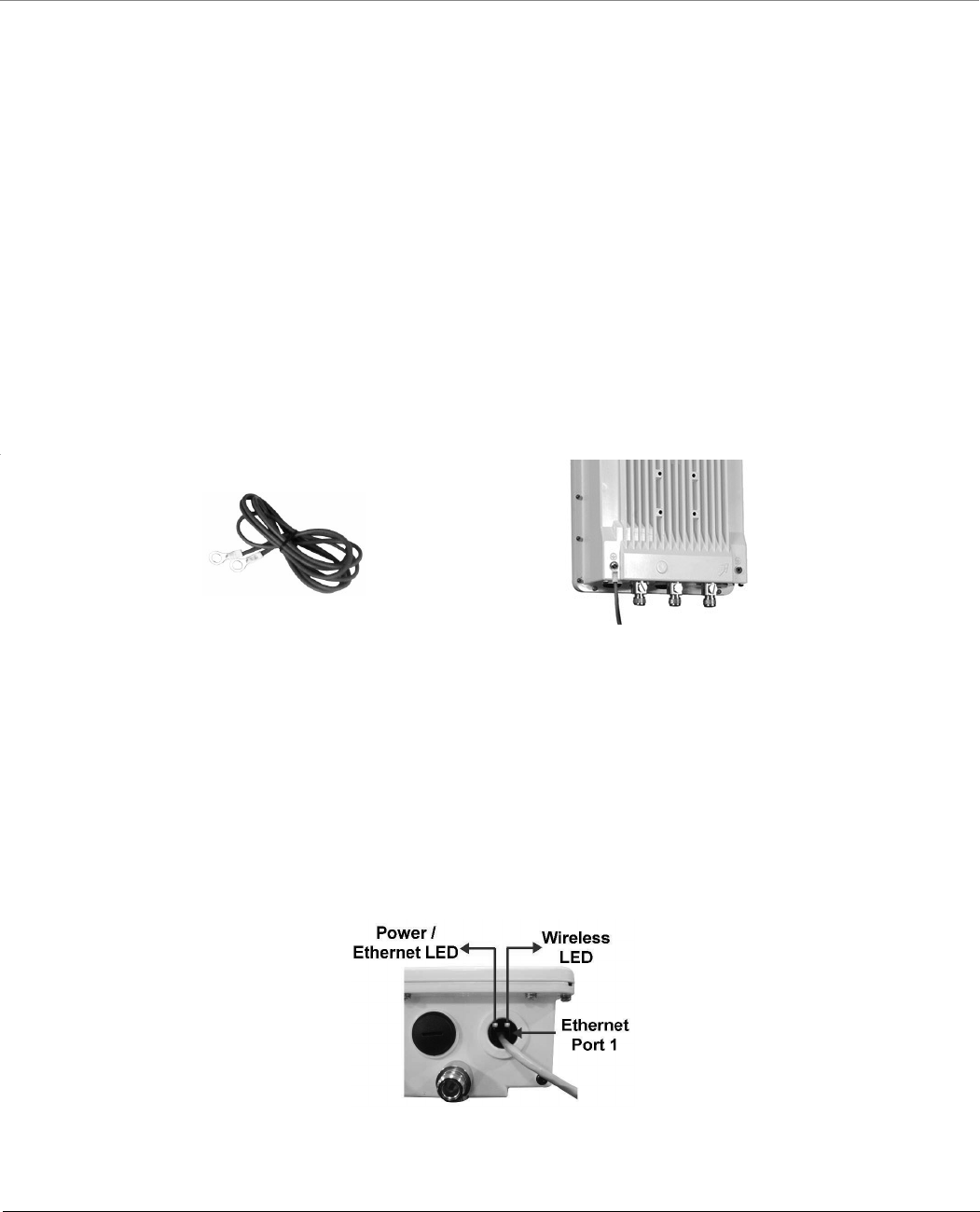
Step 11: View LEDs
When the device is powered on, it performs startup diagnostics. When startup is complete, the LEDs show the device’s
operational state. The LEDs are available at the device’s Ethernet connector inside the enclosure. You can see the LED through
the Ethernet connector. The LEDs will not be visible if the RJ45 connector is weatherproofed.

8000 Series - Hardware Overview and Installation
Tsunami® 800 and 8000 Series - Hardware Installation Guide 87
Figure 3-40 LED Indicators
The following table describes the status of LED:
LED State Ethernet Interface
Power/Ethernet LED Wireless LED
Off No Power Radio is not present or failed to detect
Amber No Application Image detected
(ScanTool mode)
Power is ON and device detects Reload
signal
Blinking Green Power is ON and the Ethernet link is
DOWN
Radio is detected but wireless link has
not been established yet
Solid Green Power is ON and the Ethernet link is UP Radio is detected and wireless link has
been established
8000 Series - Hardware Overview and Installation
Tsunami® 800 and 8000 Series - Hardware Installation Guide 88
3.5 MP-8150-SUR-100 / QB-8150-LNK-100
This section provides the hardware overview and installation method for the following product(s):
MP-8150-SUR-100
QB-8150-LNK-100
3.5.1 Hardware Overview
Figure 3-41 MP-8150-SUR-100 / QB-8150-EPR-100
A detailed description about the various components of the device are explained in the following sections.
3.5.1.1 Gigabit Ethernet Port
The device comes with one auto-sensing 10/100/1000 BASE-T Ethernet port with configurable Tx Modes and speeds.
The Gigabit Ethernet port (PoE IN and Data) of the device allows the user to connect to the LAN by using Cat5e/Cat6 Ethernet
cable, and also power ON the device by using the Power over Ethernet (PoE) Injector supplied with the product package.
The device receives 48 VDC via a a standard Cat5e/Cat6 cable connected between the PoE and the device.
Maximum power supplied to the device is 32 Watts and the device typically draws 6 Watts.
Above 0° Celsius internal temperature, the device does not regulate its temperature, so the power drawn is generally lower in
this temperature range. When the internal temperature gets close to the limits, the device starts to heat itself and the power
draw increases. Powering the device when it is cold, triggers a special self-heat mode where the device is inoperable until the
internal temperature is above -20° Celsius. This is signaled by a solid yellow LED on the Ethernet connector. Once the internal
temperature is above -20° Celsius, the device boots normally.
: Always use a straight cable from PoE to the device. When you use a 4-pair cross over ethernet cable, the reload
functionality gets activated and forcibly deletes the operating image.
Recommended Ethernet Cable Specifications
Type Cat5e/Cat6, STP, 24 AWG, UL rated, UV-shielded and outdoor-rated
Impedance 100 ohms
Cable Length 330 feet / 100 meters
: The total length of cabling between the Personal Computer and the device
cannot exceed 100 meters (includes cable from the Personal Computer to
the PoE, and the cable from the PoE to the device). Due to DC power
requirements, the maximum cable length between the PoE Injector and the
device is 75 meters.
8000 Series - Hardware Overview and Installation
Tsunami® 800 and 8000 Series - Hardware Installation Guide 89
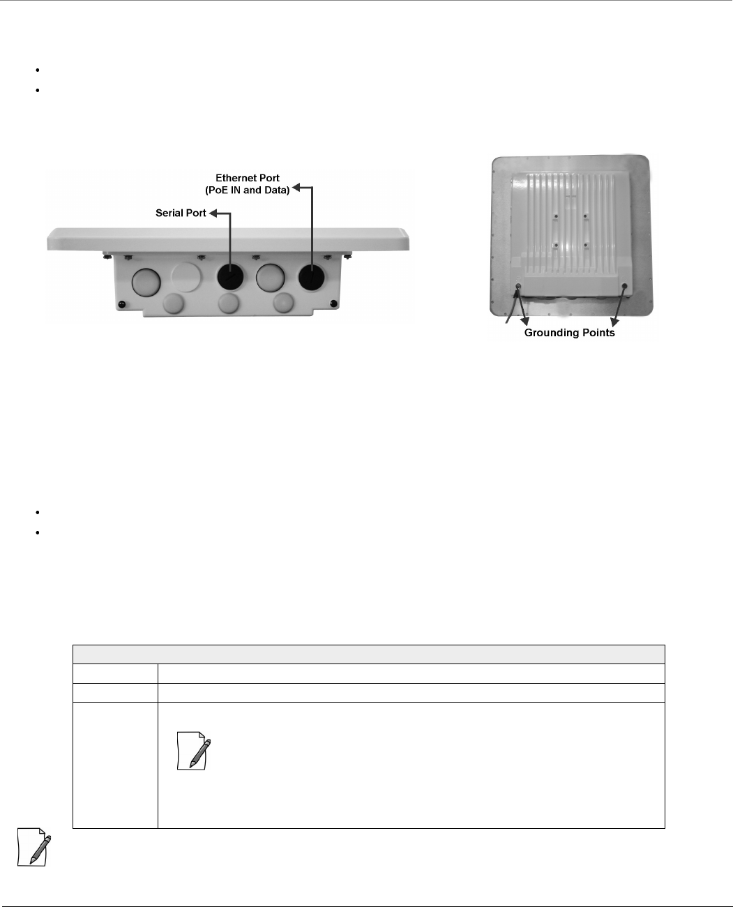
3.5.1.2 Serial Port
The Serial Port is used for debugging and management, and Audible Antenna Alignment through Command Line Interface
(CLI).
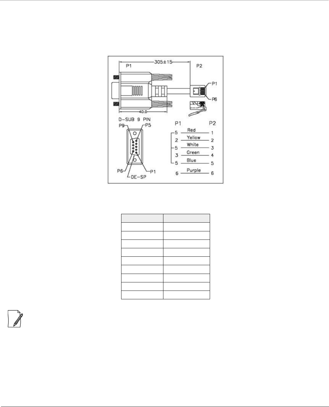
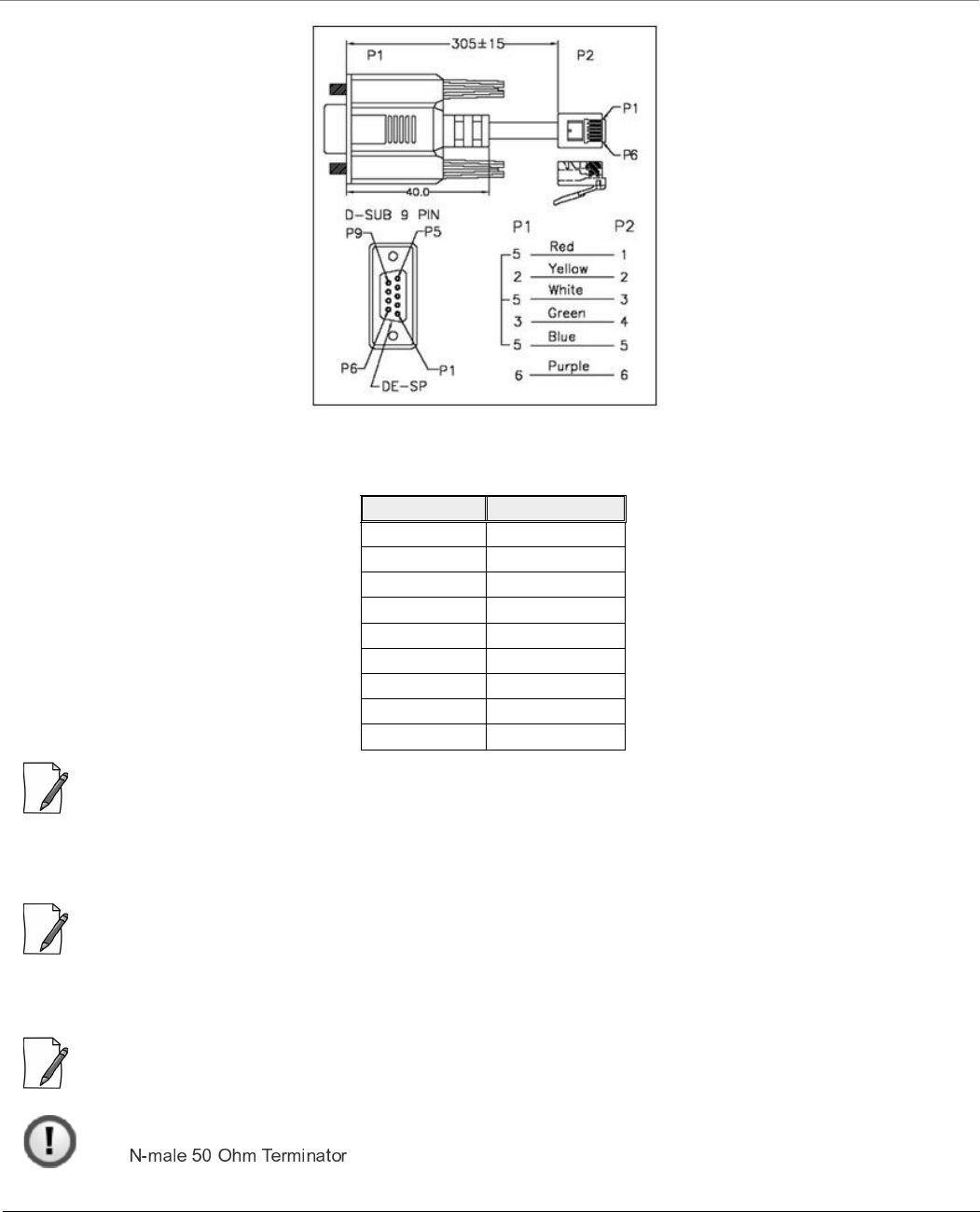
The serial connection is established with an RJ11 to DB9 connector (also referred to as a “dongle”) by connecting the RJ11
end of the dongle connector to the device and the other end to your Personal Computer.
Figure 3-42 Serial Components
The pin assignments for DB9 connector are as follows:
: The pin6 on RJ11 connector is used as input for 12V DC IN for diagnostic purpose. Supplying power on this pin, when
the device is powered by POE injector, might damage the device.
3.5.1.3 Grounding Point
To protect the device against lighting or ESD events, you must ground the device properly. To ensure proper grounding, use
either of the ground points that are situated at the bottom corner of the device and the grounding screw (#8-32 thread size)
provided to attach a ground wire of at least 10 AWG stranded to the device.
D-Shell RJ11
1 NC
2 2
3 4
4 NC
5 1 + 3 + 5
6 6
7 NC
8 NC
9 NC
8000 Series - Hardware Overview and Installation
Tsunami® 800 and 8000 Series - Hardware Installation Guide 90
3.5.2 Product Package
Each shipment includes the items listed in the following table. Please verify that you have received all the parts in the
shipment, prior to installation.
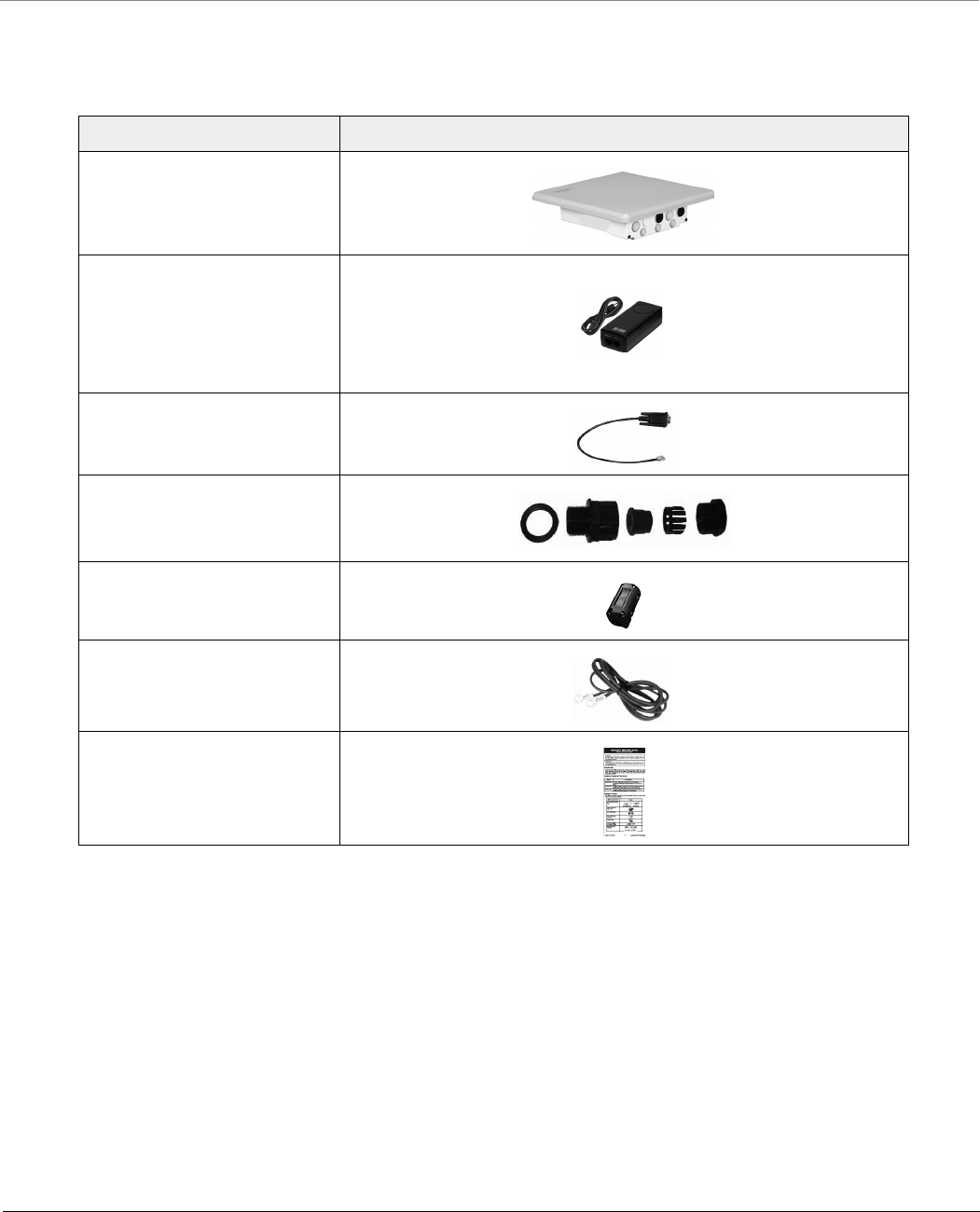
What’s in the Kit Image
MP-8150-SUR-100/
QB-8150-EPR-100
PoE Injector with Country
specific Power Cord
WD - US, UK and EU power cords
US - US power cord
EU - UK and EU power cords
RJ11 to DB9 Serial Connector
Connector Weather Proofing
Kit
EMI Toroid
Grounding Kit
Quick Installation Guide
8000 Series - Hardware Overview and Installation
Tsunami® 800 and 8000 Series - Hardware Installation Guide 91
: QB-8150-LNK-100 contains two sets of all the above accessories.
3.5.3 Installation Procedure
This section describes the steps to install and mount the device(s).
: The device must be installed by a trained professional who is familiar with radio frequency planning and
the regulatory limits.
Mounting Kit and Hardware
The mounting kit includes the following:
Mounting clamp for wall/pole
Extension arm
Mounting plate to enclosure
Mounting clamp for pole mounting
The following table lists the items included with the mounting kit:
What’s in the Kit Image
Quantity Description Image
6 each Plain washer #5/16
2 each Hex Cap Screw NC 5/16-18 x 35
2 each Nut NC 5/16-18
4 each Helical Spring Lock Washer #1/4
4 each Helical Spring Lock Washer #5/16
2 each Hex Cap Screw NC 5/16-18 x 80
4 each 68764, Screw, Machine, Pan,
Philips, 1/4"-20, 5/8"L

8000 Series - Hardware Overview and Installation
Tsunami® 800 and 8000 Series - Hardware Installation Guide 92
Perform the following steps to install and mount the device.
Step 1: Plan for Installation
There are several planning factors to be considered before installing the device. In addition to selecting the installation site,
you should do the following:
Calculate:
Required RSL and fade margin to achieve link availability objectives. For more details on how to calculate RSL and fade
margin, please refer to the ‘Antenna Installation Guide’ and ‘Proxim Link Calculator’ that are available on the support
site at .
Required path availability
Anticipated multi-path reflection points
Determine:
System frequency plan
Required antenna mounting height to obtain proper path clearance
Required transmission line types (like cable, waveguides) and lengths
Plan for:
Device’s continuous power consumption needs
Lightning protection and system grounding
Hardware mounting
Cable installation including egress
Pre-testing equipment (back-to-back test procedure)
Step 2: Choose a Location
To make optimal use of the device, you must find a suitable location to install the hardware. The range of the radio device
largely depends upon the position of the antenna. Proxim recommends you do a site survey, observing the following
requirements, before mounting the hardware.
The location must allow easy disconnection of power to the radio, if necessary.
Ensure free flow of air around the hardware.
The radio device must be kept away from vibration and excessive heat.
The installation must conform to local regulations at all times.
The devices are designed to directly mount to a pole. Using the supplied brackets and hardware, you can mount them to a
1.25 inch to 3-inch pole (outside diameter). Longer bolts (not supplied) are required for mounting the device to a larger
diameter pole. By using just one of the pole mounting brackets, you can mount the device to a wall or other flat surface.
Step 3: Gather Required Tools
You should have the following tools available before installing the device:
Cross-tip screwdrivers
Small blade standard screwdriver
Large blade standard screwdriver
Wire crimpers (if using connectors that are not pre-made)
Adjustable 6” wrench
Weatherproofing material for sealing external connectors (such as butyl tape)
Straight-through UV-protected STP-rated Cat5e/Cat6 Ethernet cable for connecting to PC, or cable for connecting to a
hub or a switch.
8000 Series - Hardware Overview and Installation
Tsunami® 800 and 8000 Series - Hardware Installation Guide 93
Step 4: Unpack the Product Package
1. Unpack the device and its accessories from the shipping box.
2. Please make a note of the Ethernet addresses, MAC addresses and the serial number. These addresses may be used
when configuring the device. Note that the serial number helps you to seek support from the Proxim’s Customer
support team.
Step 5: Weatherproofing RJ45 Connectors
The following steps explain how to weatherproof the RJ45 connectors:
1. Use a straight-through cable (Cat5e/Cat6) with one end bare.
2. Connect the crimped RJ45 connector end of the cable into the RJ45 Ethernet port inside the enclosure. The cable
connector should latch into the Ethernet port.
3. Slide the Flat Washer (A) into the Connector Body (B) to make it waterproof and onto the bare end of the cable. Next,
fasten the Connector Body into the Ethernet connector hole on the device.
4. Slide the tube-shaped Compression Washer (C) into the Compression Ring (D) and onto the cable from the bare end,
and insert into the fixed Connector Body.
5. Slide the Sealing Nut (E) over the bare end of the cable and fasten it on the fixed Connector Body.
6. Crimp the bare end of the cable with RJ45 connector and connect it to the PWR LAN-OUT port on the PoE Injector.
7. Open the notch on both sides of the toroid and fix it on Ethernet cable. Then, lock the notch of the Toroid by pressing
it.
: To avoid electro magnetic emissions, please ensure to fix Toroid to the Ethernet cable.
Figure 3-43 Weatherproofing RJ45 Connector
Additional Weatherproofing Steps
To add an additional layer of protection to the connectors against the environment, see
.
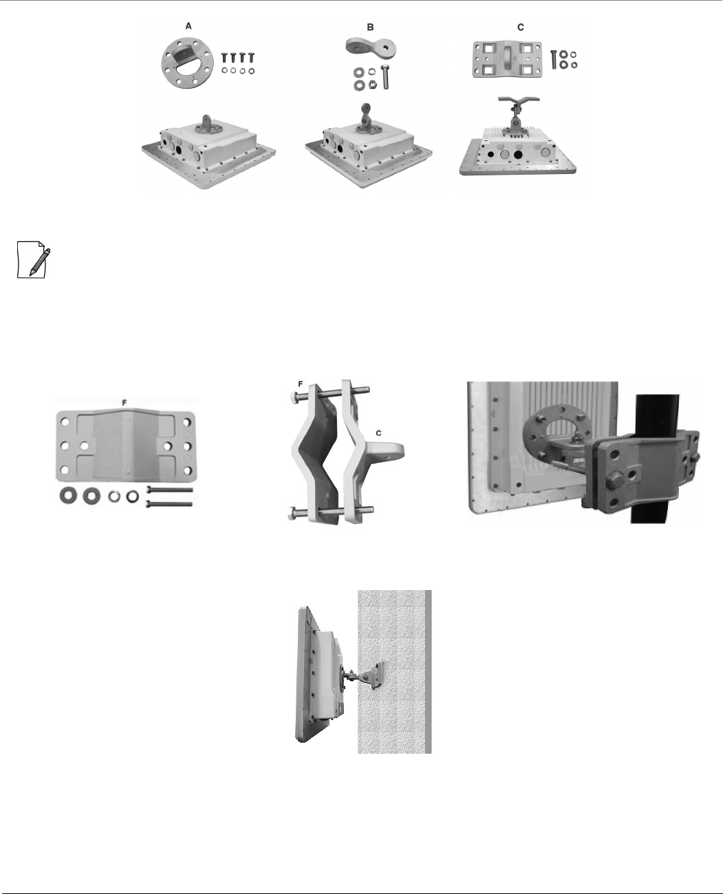
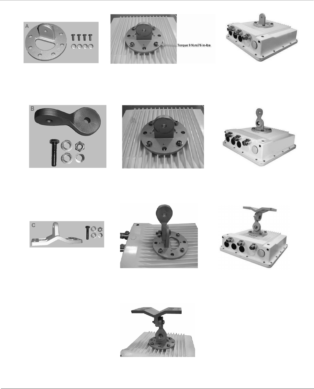
Step 6: Assemble Mounting Hardware
Fix the Mounting Plate (A) by using the provided screws and washers (Torque 9 N.m/75 in-lbs) onto the bottom of the device.
Fix the Extension Arm (B) to the fixed mounting plate with the provided screw, nut and washers. The extension arm gives the
device more possible tilt, letting you adjust for azimuth or elevation over a larger angle. Fix the Mounting Bracket (C) to the
fixed Extension Arm with the provided screw, nut and washers. Tighten the assembled parts (Torque 15 N.m/130 in-lbs). The
last picture in the following figure shows the fully assembled mounting hardware fixed to the device.
8000 Series - Hardware Overview and Installation
Tsunami® 800 and 8000 Series - Hardware Installation Guide 94
Figure 3-44 Assemble the Mounting Hardware
: This figure is for illustration only. Device should be mounted in square position with Ethernet/Serial port facing
downward.
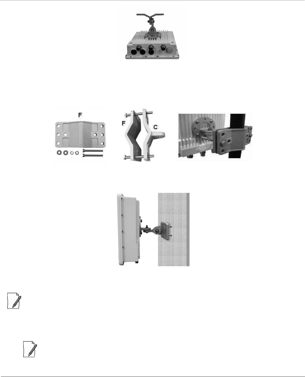
Step 7: Mount the Device
1. To pole-mount the device, insert the provided screws through bracket (F). Fasten around the pole to bracket (C) and
secure (Torque 11 N.m/100 in-lbs).
Figure 3-45 Pole Mounting
2. To wall-mount the device, mount the bracket to a wall using 4 screws (not provided).
Figure 3-46 Wall Mounting
8000 Series - Hardware Overview and Installation
Tsunami® 800 and 8000 Series - Hardware Installation Guide 95
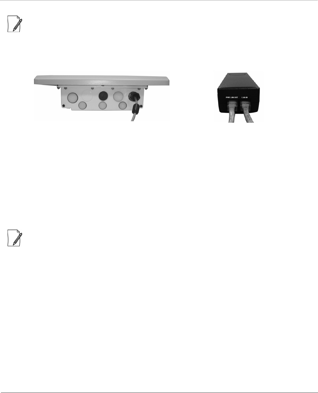
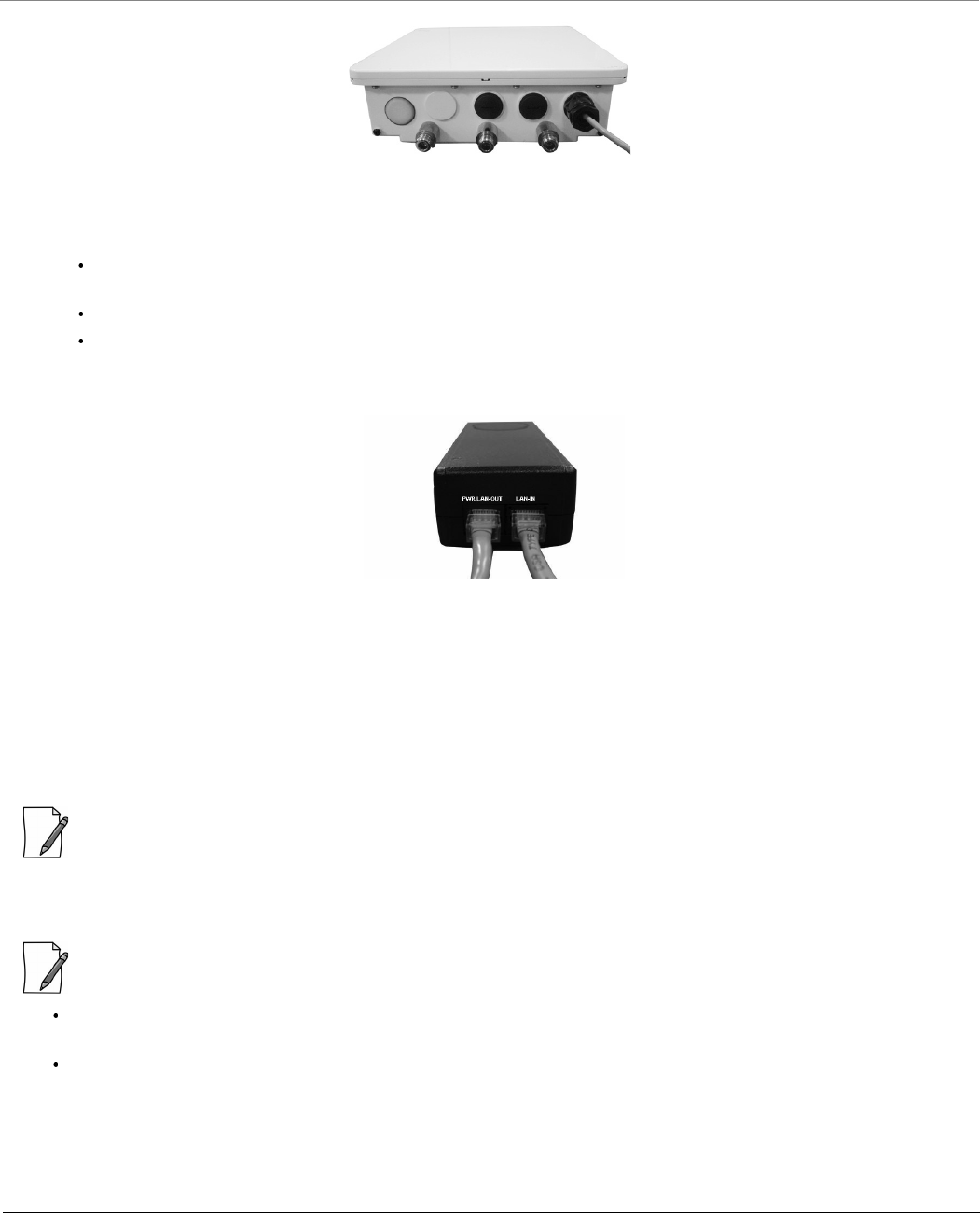
Step 8: Plug in the Cables
: Unscrew the sealing cap for installation of the cable. Always use a straight cable from PoE to the device. When you
use a 4-pair cross over ethernet cable, the reload functionality gets activated and forcibly deletes the operating image.
1. Plug one end of the straight-through Cat5e/Cat6 cable into the Ethernet Port interface of the device by following the
Weatherproofing steps explained under Step 5. Connect the other end of the cable into the PWR LAN-OUT port on
the PoE Injector.
Figure 3-47 Cable Plugged In
2. Optionally, plug the Serial cable into the serial RJ11 telephone jack inside the enclosure for debugging and
management, and audible antenna alignment.
3. To connect the device through a hub or a switch to a Personal Computer, connect an Ethernet cable between the
network interface card in the Personal Computer and the hub, and between the hub and the RJ45 LAN-IN port on the
PoE Injector.
4. To connect the device directly to a Personal Computer, connect an Ethernet cable between the network interface card
in the Personal Computer and the RJ45 LAN-IN port on the PoE Injector.
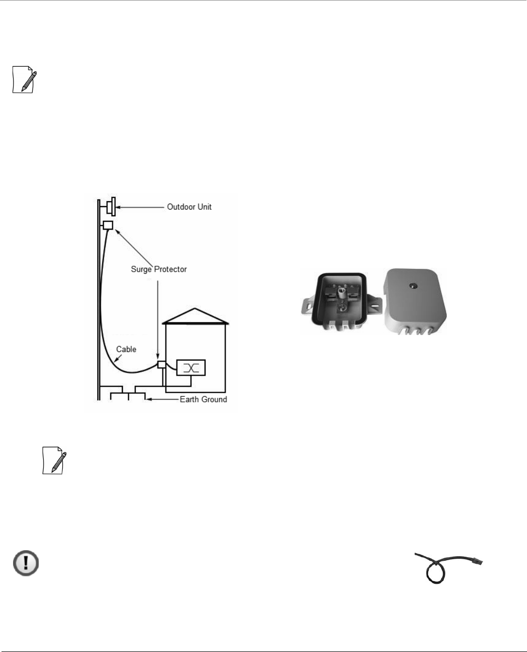
Step 9: Install Surge Protector
Proxim recommends two approved lightning surge protectors to be installed, one near to the device and the other at the
building ingress point.
: To buy a suitable Surge Protector, place an order separately with your distributor.
Perform the following steps to ensure proper surge protection:
1. Mount the surge protector near the outdoor device and use 10 AWG or larger wire to connect the protector’s ground
lug to the appropriate mounting ground point. The outdoor device and co-located surge protector should have a
common grounding point by using the shortest possible grounding cable.
2. Mount a second surge protector near the building ingress and use 10 AWG or larger wire to connect the surge
protector’s ground lug to earth ground as shown in the following figure.
8000 Series - Hardware Overview and Installation
Tsunami® 800 and 8000 Series - Hardware Installation Guide 96
Figure 3-48 Surge Protector
: Use Outdoor-rated, UV protected, shielded Cat5e/Cat6 cable for the following.
3. Connect an RJ45 terminated cable between the indoor equipment and to the port on the surge protector at the
building ingress.
4. Connect a short RJ45 terminated cable between the outdoor equipment and the port on the co-located surge
protector.
5. Connect an RJ45 terminated cable between the two surge protectors on their remaining ports.
: Ensure to loop the cable before entering the premise to prevent water ingress.
Step 10: Ground the Unit
To ensure proper grounding, use either of the ground points which are situated at the bottom corners of the device and the
grounding screw provided to attach a ground wire of at least 10 AWG stranded to the device. It is important that the
following grounding guidelines are followed to protect the device against lighting or ESD events:
1. Connect one end of the grounding cable to the device as shown in the and the other end to the closest
earthing system point at the installation.
2. Cut any extra ground wire length when finished connecting it to the single point earth ground.
3. Avoid sharp bends and never loop or coil up the ground wire, always connect it straight to ground.
4. A good earth ground impedance is less than 1.0 ohm.
5. Measure ground impedance at the point where the surge protector ground wire is connected and not at the ground
rod.
6. Connect the surge protector ground wire and equipment ground (both power ground and telecomm ground) to a
single common ground.
7. Make sure all connections are fastened securely and are tight.
8. Never install during a storm and always follow your local safety codes.
8000 Series - Hardware Overview and Installation
Tsunami® 800 and 8000 Series - Hardware Installation Guide 97
Figure 3-49 Ground the Device
Step 11: Power ON the Device
Plug in the power cord into a power outlet after having connected the PoE Injector and the device using straight-through
Cat5e/Cat6 cable. There is no ON/OFF switch on the device. To disconnect power, unplug the RJ45 connector from the PWR
LAN-OUT port on the PoE injector.
Step 12: View LEDs
When the device is powered on, it performs startup diagnostics. When startup is complete, the LEDs show the device’s
operational state. The LEDs are available at the device’s Ethernet connector inside the enclosure. You can see the LEDs
through the ethernet connector. The LEDs will not be visible if the RJ45 connector is weatherproofed.
Figure 3-50 View LEDs
The following table states the status of LEDs and the corresponding operational state of the device:
LED State Power/Ethernet LED Wireless LED
Ethernet
Yellow Device is self heating (Cold Start) Power is ON and the device detects
Reload signal
Off No Power Radio is not present or failed to detect
Blinking Green-Fast Power is ON and the Ethernet link on
Ethernet is DOWN
Radio is ON and wireless link has not
been established yet
Blinking Green
(5 times) and turns off
Bootloader detected no image Not Applicable
Green Power is ON and the Ethernet link on
Ethernet is UP
Wireless link has been established
8000 Series - Hardware Overview and Installation
Tsunami® 800 and 8000 Series - Hardware Installation Guide 98
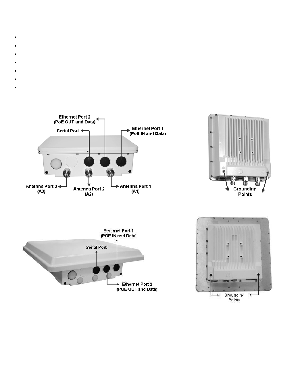
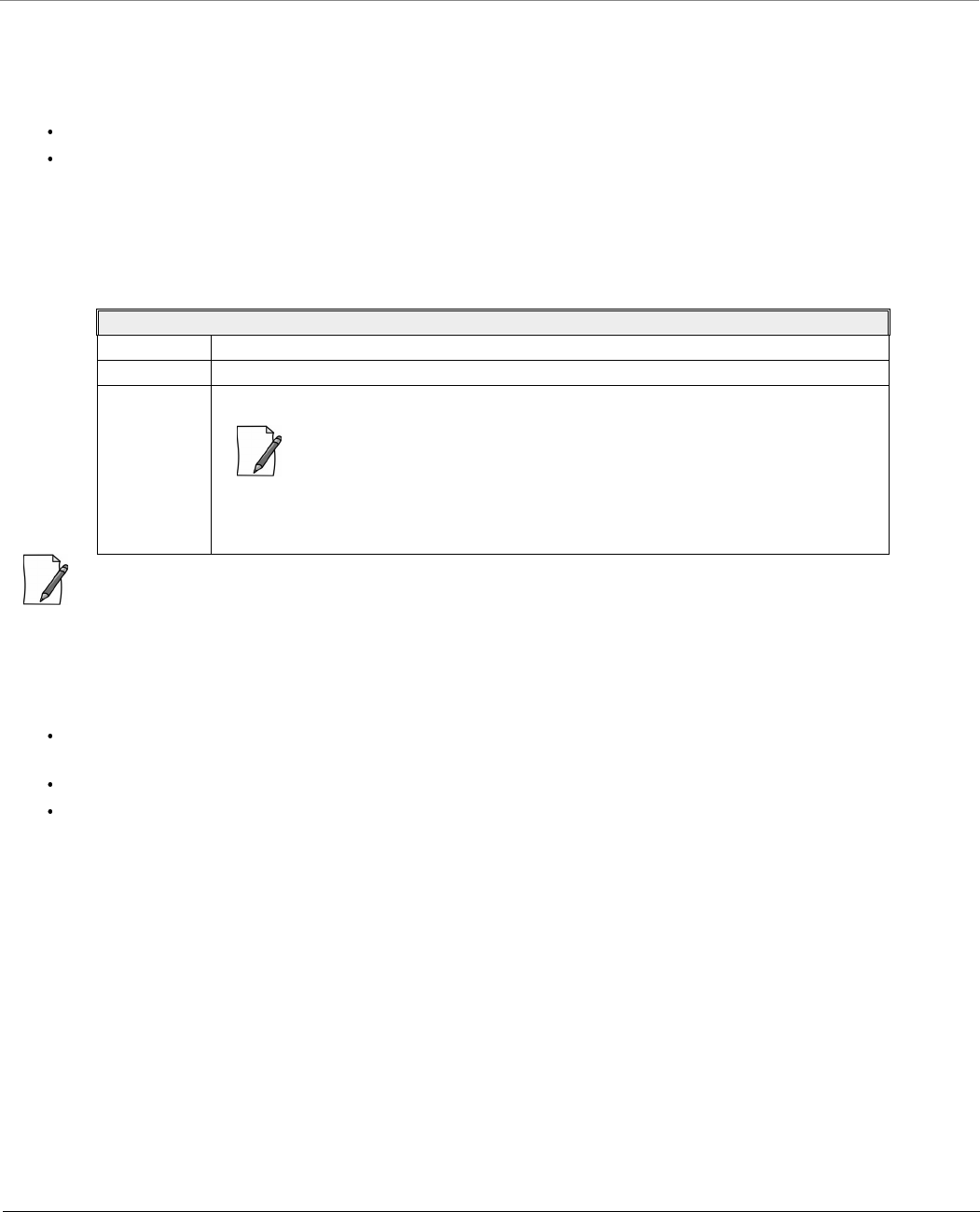
3.6 MP-8200-BSU / MP-8200-SUA / MP-8250-SUR / QB-8200-EPA&LNK
/QB-8250-EPR&LNK / MP-8250-BS9 / MP-8250-BS1
This section provides the hardware overview and installation procedure for the following product(s):
MP-8200-BSU
MP-8250-BS9
MP-8250-BS1
MP-8200-SUA
MP-8250-SUR
QB-8200-EPA/LNK
QB-8250-EPR/LNK
3.6.1 Hardware Overview
Figure 3-51 MP-8200-BSU / MP-8200-SUA / QB-8200-EPA
Figure 3-52 MP-8250-SUR / MP-8250-BS9 / MP-8250-BS1 / QB-8250-EPR
A detailed description about the various components of the device are explained in the following sections.
3.6.1.1 Gigabit Ethernet Ports
The device comes with two auto-sensing 10/100/1000 BASE-T Ethernet ports with configurable Tx Modes and Speeds.
8000 Series - Hardware Overview and Installation
Tsunami® 800 and 8000 Series - Hardware Installation Guide 99
3.6.1.1.1 a) Ethernet Port 1
The Gigabit Ethernet port 1 (PoE IN and Data) of the device allows the user to connect to the LAN by using Cat5e/Cat6
Ethernet cable, and also power ON the device by using the Power over Ethernet (PoE) Injector supplied with the product
package.
The device receives 48 VDC via a standard Cat5e/Cat6 cable connected between the PoE and the device.
Maximum power supplied to the device is 32 Watts and the device typically draws 12 Watts.
Above 0° Celsius internal temperature, the device need not regulate its temperature, so the power drawn is generally lower in
this temperature range. When the internal temperature gets close to the limits, the device starts to heat itself and the power
draw increases. Powering the device when it is cold, triggers a special self-heat mode where the device is inoperable until the
internal temperature is above -20° Celsius. This is signaled by a solid yellow LED on the Ethernet connector. Once the internal
temperature is above -20° Celsius, the device boots normally.
: Always use a straight cable from PoE to the device. When you use a 4-pair cross over ethernet cable, the reload
functionality gets activated and forcibly deletes the operating image.
3.6.1.1.2 b) Ethernet Port 2
The Gigabit Ethernet Port 2 is used for PoE OUT and data. While using this port, the following points should be considered:
48 VDC (15 W average) is present on the second Ethernet port. Make sure the connected device can support this
voltage.
If power from the second Ethernet Port is desired, then Proxim recommends you to use 60W PoE (not supplied).
If a device is connected to the second Ethernet port for data only, then use a PoE Splitter (not supplied).
3.6.1.2 Serial Port
The Serial Port is used for debugging and management, and Audible Antenna Alignment through Command Line Interface
(CLI).
The serial connection is established with an RJ11 to DB9 connector (also referred to as a “dongle”) by connecting the RJ1 end
of the dongle connector to the device and the other end to your Personal Computer.
Recommended Ethernet Cable Specifications
Type Cat5e/Cat6, STP, 24 AWG, UL rated, UV-shielded and outdoor-rated
Impedance 100 ohms
Cable Length 330 feet / 100 meters
: The total length of cabling between the Personal Computer and the device
cannot exceed 100 meters (includes cable from the Personal Computer to
the PoE, and the cable from the PoE to the device. Due to DC power
requirements, the maximum cable length between the PoE Injector and the
device is 75 meters.
8000 Series - Hardware Overview and Installation
Tsunami® 800 and 8000 Series - Hardware Installation Guide 100
Figure 3-53 Serial Components
The pin assignments for DB9 connector are as follows:
: The pin6 on RJ11 connector is used as input for 12V DC IN for diagnostic purpose. Supplying power on this pin, when
the device is powered by POE injector, might damage the device.
3.6.1.3 Antenna Ports
: Applicable only to MP-8200-BSU, MP-8200-SUA and QB-8200-EPA/LNK.
The Antenna Ports A1, A2 and A3 are used to connect external antenna (s). These antenna connectors are of N-Type female
with built-in surge protection.
: Use antenna port A1 for single polarization antennas, and antenna ports A1 and A3 for dual polarization antennas. By
default, A1 and A3 ports are enabled. Enable A2 port, in case you are using 3*3 antennas.
: When using a single polarized or dual polarized antenna, ensure to terminate the unused antenna ports
with (supplied with the product package). Not doing so may damage the radio
card. To buy an additional N-male 50 Ohm Terminator, place an order separately with your distributor.
D-Shell RJ11
1 NC
2 2
3 4
4 NC
5 1 + 3 + 5
6 6
7 NC
8 NC
9 NC
8000 Series - Hardware Overview and Installation
Tsunami® 800 and 8000 Series - Hardware Installation Guide 101
3.6.1.4 Grounding Points
To protect the device against lighting or ESD events, you must ground the device properly. To ensure proper grounding, use
either of the ground points that are situated at the bottom corner of the device and the grounding screw (#8-32 thread size)
provided to attach a ground wire of at least 10 AWG stranded to the device.
3.6.2 Product Package
Each shipment includes the items listed in the following table. Please verify that you have received all the parts in this
shipment, prior to installation.
What’s in the Kit Image
MP-8200-BSU/
MP-8250-BS9/
MP-8250-BS1/
MP-8200-SUA/
MP-8250-SUR/
QB-8200-EPA/LNK
QB-8250-EPR/LNK
PoE Injector with Country specific Power
Cord
WD - US, UK and EU power cords
US and JP* - US power cord
EU - UK and EU power cords
* Not for MP-8250-BS9, MP-8250-BS1
RJ11 to DB9 Serial Connector
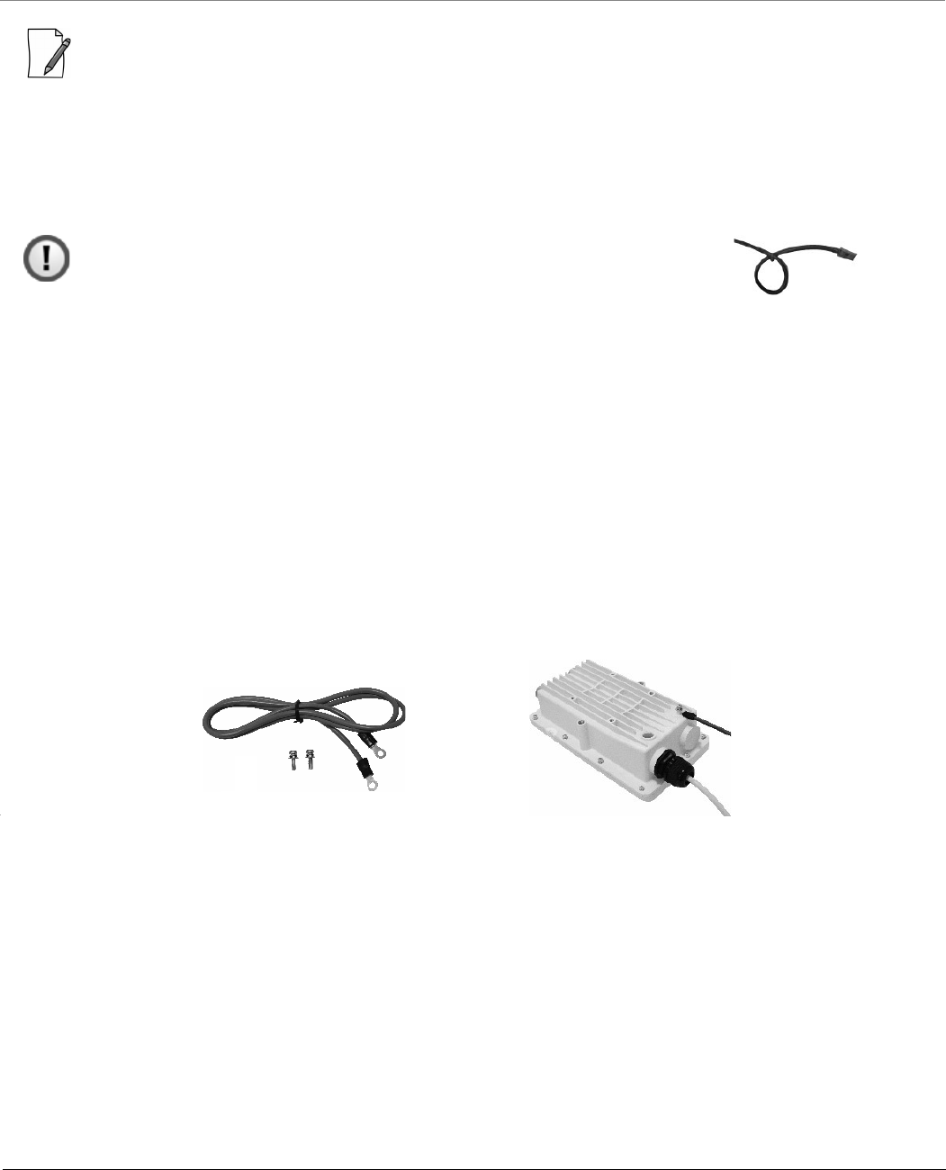
Connector Weather Proofing Kit (2 sets)
PoE Surge Arrestor
Grounding Kit
MP-8200-BSU/SUA
QB-8200-EPA
MP-8250-SUR / QB-8250-EPR
MP-8250-BS9/BS1
8000 Series - Hardware Overview and Installation
Tsunami® 800 and 8000 Series - Hardware Installation Guide 102
: QB-8200-LNK and QB-8250-LNK contains two sets of all the above accessories.
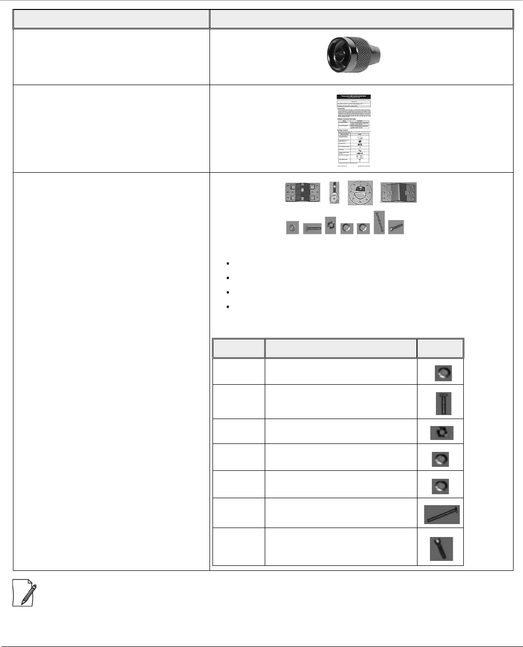
N-male 50 Ohm Terminator
Supplied with MP-8200-BSU, MP-8200-SUA and
QB-8200-EPA/LNK devices only
Quick Installation Guide
Mounting Kit and Hardware
The mounting kit includes the following:
Mounting clamp for wall/pole
Extension arm
Mounting plate to enclosure
Mounting clamp for pole mounting
The following table lists the items included with the mounting kit:
What’s in the Kit Image
Quantity Description Image
6 each Plain washer #5/16
2 each Hex Cap Screw NC 5/16-18 x 35
2 each Nut NC 5/16-18
4 each Helical Spring Lock Washer #1/4
4 each Helical Spring Lock Washer #5/16
2 each Hex Cap Screw NC 5/16-18 x 80
4 each 68764, Screw, Machine, Pan,
Philips, 1/4"-20, 5/8"L

8000 Series - Hardware Overview and Installation
Tsunami® 800 and 8000 Series - Hardware Installation Guide 103
3.6.3 Installation Procedure
This section describes the steps to install and mount the device(s).
: Please note that we have taken MP-8200-BSU as an example to explain the steps to install and mount the device.
Please correlate the same with your device.
: The device must be installed by a trained professional who is familiar with radio frequency planning and
regulatory limits.
Perform the following steps to install and mount the device.
Step 1: Plan for Installation
There are several planning factors to be considered before installing the device. In addition to selecting the installation site,
you should do the following:
Calculate:
Required RSL and fade margin to achieve link availability objectives. For more details on how to calculate RSL and fade
margin, please refer to the ‘Tsunami® 800 and 8000 Series - Antenna Installation Guide’ and ‘Proxim Link Calculator’
that are available on the support site at .
Required path availability
Anticipated multi-path reflection points
Determine:
System frequency plan
Required antenna mounting height to obtain proper path clearance
Required transmission line types (like cable, waveguides) and lengths
Plan for:
Device’s continuous power consumption needs
Lightning protection and system grounding
Hardware mounting
Cable installation including egress
Pre-testing equipment (back-to-back test procedure)
Step 2: Choose a Location
To make optimal use of the device, you must find a suitable location to install the hardware. The range of the radio device
largely depends upon the position of the antenna. Proxim recommends you do a site survey, observing the following
requirements, before mounting the hardware.
The location must allow easy disconnection of power to the radio, if necessary.
Ensure free flow of air around the hardware.
The radio device must be kept away from vibration and excessive heat.
The installation must conform to local regulations at all times.
The devices are designed to directly mount to a pole. Using the supplied brackets and hardware, you can mount them to a
1.25 inch to 3-inch pole (outside diameter). Longer bolts (not supplied) are required for mounting the device to a larger
diameter pole. Using just one of the pole mounting brackets, you can mount the device to a wall or other flat surface.
8000 Series - Hardware Overview and Installation
Tsunami® 800 and 8000 Series - Hardware Installation Guide 104
Step 3: Gather Required Tools
You should have the following tools available before installing the device:
Cross-tip screwdrivers
Small blade standard screwdriver
Large blade standard screwdriver
Wire crimpers (if using connectors that are not pre-made)
Adjustable 6” wrench
Weatherproofing material for sealing external connectors (such as butyl tape)
Straight-through UV-protected STP-rated Cat5e/Cat6 Ethernet cable for connecting to PC, or cable for connecting to a
hub or a switch.
Step 4: Unpack the Product Package
1. Unpack the device and its accessories from the shipping box.
2. Please make a note of the Ethernet addresses, MAC addresses and the serial number. These addresses may be used
when configuring the device. Note that the serial number helps you to seek support from the Proxim’s Customer
support team.
Step 5: Weatherproofing RJ45 Connectors
The following steps explain how to weatherproof the RJ45 connectors:
1. Use a straight-through cable (Cat5e/Cat6) with one end bare.
2. Connect the crimped RJ45 connector end of the cable into the RJ45 Ethernet port inside the enclosure. The cable
connector should latch into the Ethernet port.
3. Slide the Flat Washer (A) into the Connector Body (B) to make it waterproof and onto the bare end of the cable. Next,
fasten the Connector Body into the Ethernet connector hole on the device.
4. Slide the tube-shaped Compression Washer (C) into the Compression Ring (D) and onto the cable from the bare end,
and insert into the fixed Connector Body.
5. Slide the Sealing Nut (E) over the bare end of the cable and fasten it on the fixed Connector Body.
6. Crimp the bare end of the cable with RJ45 connector and connect it to the PWR LAN-OUT port on the PoE Injector.
Figure 3-54 Weatherproofing RJ45 Connector
Additional Weatherproofing Steps
For detailed explanation to weatherproof RJ45 connectors, refer to .
For detailed explanation to weatherproof RF connections, refer to Tsunami® 800 and 8000 Series Antenna Installation
Guide, which is available at .
Step 6: Assemble Mounting Hardware
1. Fix the Mounting Plate (A) by using the provided screws and washers (Torque 9 N.m/75 in-lbs).
8000 Series - Hardware Overview and Installation
Tsunami® 800 and 8000 Series - Hardware Installation Guide 105
2. Fix the Extension Arm (B) to the fixed Mounting Plate with the provided screw, nut and washers. The Extension Arm
gives the device more possible tilt, letting you adjust for azimuth or elevation over a larger angle.
3. Fix the Mounting Bracket (C) to fixed Extension Arm with the provided screw, nut and washers.
4. Tighten the assembled parts (Torque 15 N.m/130 in-lbs).
The following figure shows the fully assembled mounting hardware fixed to the device.
Mounting Plate Fixing Mounting Plate
to the device
Mounting Plate fixed to
the Device
Extension Arm Mounting Plate fixed to the device Extension Arm fixed to
Mounting Plate
Mounting Bracket Extension Arm fixed to
Mounting Plate
Mounting Bracket fixed to
Extension Arm
8000 Series - Hardware Overview and Installation
Tsunami® 800 and 8000 Series - Hardware Installation Guide 106
Figure 3-55 Assembled Device
Step 7: Mount the Device
1. To pole-mount the device, insert the provided screws and washers through bracket (F). Fasten around the pole to
bracket (C) and secure (Torque 11 N.m/100 in-lbs).
Figure 3-56 Pole Mounting
2. To wall-mount the device, mount the bracket (C) to a wall by using 4 screws (not supplied), as shown:
Figure 3-57 Wall Mounting
Step 8: Plug in the Cables
: Unscrew the sealing cap for installation of the cable.
1. Plug one end of the straight-through Cat5e/Cat6 cable into the Ethernet Port 1 of the device by following the
Weatherproofing steps explained under Step5. Connect the other end of the cable into the PWR LAN-OUT port on
the PoE Injector.
: Always use a straight cable from PoE to the device. When you use a 4-pair cross over ethernet cable, the reload
functionality gets activated and forcibly deletes the operating image.
8000 Series - Hardware Overview and Installation
Tsunami® 800 and 8000 Series - Hardware Installation Guide 107
Figure 3-58 Cable Plugged In
2. Plugging in the second Cat5e/Cat6 cable into the Ethernet Port 2 interface of the device is optional. While using the
second Ethernet Port for PoE OUT and data, the following should be considered:
48 VDC (15 W average) is present on the second Ethernet port. Make sure the connected device can support this
voltage.
If power from the second Ethernet Port is desired, then Proxim recommends to use 60W PoE (not supplied).
If the device is connected to the second Ethernet port for data, then use a PoE Splitter (not supplied)
3. Optionally, connect a RJ11 to DB9 Serial Connector to device’s Serial Port for debugging and management, and
audible antenna alignment.
Figure 3-59 PoE Injector
4. To connect the device through a hub or a switch to a Personal Computer, connect an Ethernet cable between the
network interface card in the Personal Computer and the hub, and between the hub and the RJ45 LAN-IN port on the
PoE Injector.
5. To connect the device directly to a Personal Computer, connect an Ethernet cable between the network interface card
in the Personal Computer and the RJ45 LAN-IN port on the PoE Injector.
Step 9: Connect the Antenna
: Applicable only to MP-8200-BSU, MP-8200-SUA and QB-8200-EPA/LNK.
Connect the antenna to the device by connecting the straight N-male end of the cable to the device antenna port and the
right angle N-male end of the cable at the antenna.
:
Record which port each antenna polarization is associated with, to ensure that each side matches and aid in
configuration.
Ensure to use antenna port A1 for single polarization antennas, and antenna ports A1 and A3 for dual polarization
antennas.
8000 Series - Hardware Overview and Installation
Tsunami® 800 and 8000 Series - Hardware Installation Guide 108
Step 10: Install Surge Protector
Proxim recommends two approved lightning surge protectors to be installed, one near to the device and the other at the
building ingress point.
: For an additional Surge Protector, place an order separately with your distributor.
Perform the following steps to ensure proper surge protection:
1. Mount the provided surge protector near the outdoor device and use 10 AWG or a better gauge wire to connect the
protector’s ground lug to the appropriate mounting ground point. The outdoor device and co-located surge protector
should have a common grounding point using the shortest possible grounding cable.
2. Mount a second surge protector near the building ingress and use 10 AWG or a better gauge wire to connect the
surge protector’s ground lug to earth ground as shown in the figure below.
Figure 3-60 Surge Protector
: Use Outdoor-rated, UV protected, shielded Cat5e/Cat6 cable for the following:
3. Connect an RJ45 terminated cable between the indoor device and to the port on the surge protector at the building
ingress.
4. Connect a short RJ45 terminated cable between the outdoor device and the port on the co-located surge protector.
5. Connect an RJ45 terminated cable between the two surge protectors on their remaining ports.
: Ensure to loop the cable before entering the premise to prevent water ingress.
8000 Series - Hardware Overview and Installation
Tsunami® 800 and 8000 Series - Hardware Installation Guide 109
Step 11: Ground the Unit
To ensure proper grounding, use either of the ground points which are situated at the bottom corners of the device and the
grounding screw(#8-32 thread size) provided to attach a ground wire of at least 10 AWG stranded to the device. It is
important that the following ground guidelines are followed during installations to protect the device against lighting or ESD
events:
1. Connect one end of the grounding cable to the device and the other end to the closest earthing system point at the
installation.
2. Cut any extra ground wire length when finished connecting it to the single point earth ground.
3. Avoid sharp bends and never loop or coil up the ground wire, always connect it straight to ground.
4. A good earth ground impedance is less than 1.0 ohm.
5. Measure ground impedance at the point where the protector ground wire is connected and not at the ground rod.
6. Connect the surge protector ground wire and equipment ground (both power ground and telecomm ground) to a
single common ground.
7. Make sure all connections are fastened securely and are tight.
8. Never install during a storm and always follow your local safety codes.
Connect the grounding wire, which is supplied with the product package, to the device as shown below:
Figure 3-61 Ground the Device
Step 12: Power ON the Device
Plug in the power cord into a power outlet after having connected the Power Injector and the radio device by using
straight-through Cat5e/Cat6 cable. There is no ON/OFF switch on the device. To disconnect power, unplug the RJ45
connector from the PWR LAN-OUT port on the power injector.
Step 13: View LEDs
When the device is powered on, it performs startup diagnostics. When startup is complete, the LEDs show the device’s
operational state. The LEDs are available at the device’s Ethernet connector inside the enclosure. You can see the LEDs
through the ethernet connector. The LEDs will not be visible if the RJ45 connector is weatherproofed.
Figure 3-62 View LEDs

8000 Series - Hardware Overview and Installation
Tsunami® 800 and 8000 Series - Hardware Installation Guide 110
The following table states the status of LEDs and the corresponding operational state of the device:
Step 14: Align the Antennas
Antenna alignment is the process of physically aligning the antenna of the radio receiver and transmitter to have the best
possible link established between them. The antenna alignment process is usually performed during installation and after
major repairs. If you are installing external antennas, refer to the documentation that accompanies the antenna for
installation instructions.
The device has an audible antenna alignment tool that can be activated by plugging in the supplied RJ11 serial dongle. It is
audible upto 30 minutes. The CLI command enables both audible and numerical feedback as the CLI shows the running
Signal-to-Noise Ratio (SNR) values twice a second.
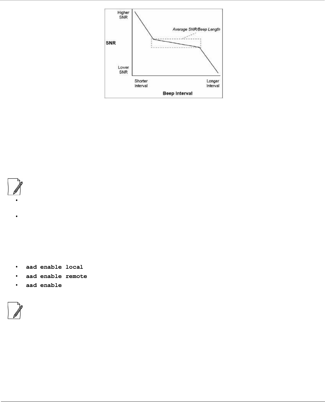
The output from the beeper for antenna alignment consists of short beeps with a variable interval. The interval changes with
the SNR level to assist in correctly aligning the antenna. An increase in signal level is indicated by a shorter interval between
beeps and a reduction in signal level results in beeps longer apart.
The alignment process averages the SNR, which is represented by an average length beep. When a higher SNR is received, the
beep period becomes shorter, dependent upon the difference to the average. A lower SNR results in a longer period between
beeps.
LED State Ethernet 1
Power/Ethernet LED Wireless LED
Yellow Device is self heating (Cold Start) Power is on and the device detects
Reload signal
Off No Power Radio is not present or failed to detect
Blinking Green-Fast Power is on and the Ethernet link on
Ethernet 1 is down
Radio is on and wireless link has not
been established yet
Blinking Green (5
times) and turns off
Bootloader detected no image Not Applicable
Green Power is on and the Ethernet link on
Ethernet 1 is up
Wireless link has been established
LED State Ethernet 2
Power/Ethernet LED Wireless LED
Yellow Not Applicable Not Applicable
Off No Power Normal Operation
Blinking Green-Fast Power is on and the Ethernet link on
Ethernet 2 is down
Not Applicable
Blinking Green (5
times) and turns off
Bootloader detected no image Not Applicable
Green Power is on and the Ethernet link on
Ethernet 2 is up
Not Applicable
8000 Series - Hardware Overview and Installation
Tsunami® 800 and 8000 Series - Hardware Installation Guide 111
Figure 3-63 Beep Interval
When the antenna is aimed, the beep intuitively represents whether the SNR is rising or falling. The higher the SNR rises, the
shorter the period of the beep is heard and the higher the frequency of the beep.
When you change the position of the antenna, SNR averaging settles at the new value and the beeping returns to the
average length so the antenna can again be aimed for rising SNR.
Aiming is complete if moving in any direction results in a falling SNR value (which can be heard as longer periods between
beeps).
:
The range of the average SNR has been limited to values from 5 to 43; therefore, anything over 43 always results in a
short period between beeps and values below 5 always have a long period.
The Antenna Alignment Display (AAD) CLI output is disabled automatically 30 minutes after it is enabled to remove
the load of extra messages on the wireless interface. The default telnet time-out is 300 seconds (5 minutes).
Antenna Alignment Commands
To enable the antenna alignment display from the CLI prompt, enter the following commands:
: Enables display of the local signal, noise and SNR.
: Enables display of the remote signal, noise and SNR.
: Enables display of local and remote signal, noise and SNR.
: Use a flat blade screw driver to disconnect and pull out the Serial cable from the enclosure after the antenna
alignment is done. After withdrawing the cables, seal the serial port carefully to avoid water seepage.

Tsunami® 800 and 8000 Series - Hardware Installation Guide 112
Technical Specifications
This chapter provides information on the following topics:
Device Models
Model Part
Number
Description
Base Stations
MP-820-BSU-100-WD 901-00133 MP 820 Base Station Unit, 100 Mbps, GPS Sync Ready, 2x2 MIMO, 2 N-Type Connectors -
WD PoE
MP-820-BSU-100-US 901-00135 MP 820 Base Station Unit, 100 Mbps, GPS Sync Ready, 2x2 MIMO, 2 N-Type Connectors -
US PoE
MP-820-BSU-100-EU 901-00162 MP 820 Base Station Unit, 100 Mbps, GPS Sync Ready, 2x2 MIMO, 2 N-Type Connectors -
EU PoE
MP-825-BS3-100-WD 901-00184 MP 820 Base Station Unit, 100 Mbps, GPS Sync Ready, 2x2 MIMO, 15 dBi Integrated
Antenna - WD PoE
MP-825-BS3-100-US 901-00185 MP 820 Base Station Unit, 100 Mbps, GPS Sync Ready, 2x2 MIMO, 15 dBi Integrated
Antenna - US PoE
MP-825-BS3-100-EU 901-00186 MP 820 Base Station Unit, 100 Mbps, GPS Sync Ready, 2x2 MIMO, 15 dBi Integrated
Antenna - EU PoE
MP-8100-BSU-US 76705 MP 8100 Base Station Unit, 300 Mbps, 3x3 MIMO, 3 N-Type Connectors - US PoE
MP-8100-BSU-WD 76708 MP 8100 Base Station Unit, 300 Mbps, 3x3 MIMO, 3 N-Type Connectors - WD PoE
MP-8100-BSU-EU 901-00158 MP 8100 Base Station Unit, 300 Mbps, 3x3 MIMO, 3 N-Type Connectors - EU PoE
MP-8160-BSU-WD 901-00109 MP 8160 Base Station Unit, 300Mbps, 2x2 MIMO, 2 N-Type Connectors - WD PoE
MP-8160-BS9-WD 901-00120 MP 8160 Base Station Unit, 300Mbps, 2x2 MIMO, 16 dBi Integrated 90 degree Sector
Antenna - WD PoE

Technical Specifications
Tsunami® 800 and 8000 Series - Hardware Installation Guide 113
MP-8200-BSU-US 901-00118 MP 8200 Base Station Unit, 300 Mbps, 3x3 MIMO, 3 N-Type Connectors - US PoE
MP-8200-BSU-WD 901-00116 MP 8200 Base Station Unit, 300 Mbps, 3x3 MIMO, 3 N-Type Connectors - WD PoE
MP-8200-BSU-JP 901-00148 MP 8200 Base Station Unit, 300 Mbps, 3x3 MIMO, 3 N-Type Connectors - JP PoE
MP-8200-BSU-EU 901-00155 MP 8200 Base Station Unit, 300 Mbps, 3x3 MIMO, 3 N-Type Connectors - EU PoE
MP-8250-BS9-US 901-00119 MP 8250 Base Station Unit, 300 Mbps, 2x2 MIMO, 16 dBi Integrated 90o Sector
Antenna - US PoE
MP-8250-BS9-WD 901-00117 MP 8250 Base Station Unit, 300 Mbps, 2x2 MIMO, 16 dBi Integrated 90o Sector
Antenna - WD PoE
MP-8250-BS9-EU 901-00165 MP 8250 Base Station Unit, 300 Mbps, 2x2 MIMO, 16 dBi Integrated 90o Sector
Antenna - EU PoE
MP-8250-BS1-US 901-00170 MP 8250 Base Station Unit, 300 Mbps, 2x2 MIMO, 23 dBi Integrated 10o Panel
Antenna - US PoE
MP-8250-BS1-WD 901-00171 MP 8250 Base Station Unit, 300 Mbps, 2x2 MIMO, 23 dBi Integrated 10o Panel
Antenna - WD PoE
MP-8250-BS1-EU 901-00172 MP 8250 Base Station Unit, 300 Mbps, 2x2 MIMO, 23 dBi Integrated 10o Panel
Antenna - EU PoE
Subscribers
MP-8100-SUA-US 76706 MP 8100 Subscriber Unit, 300 Mbps, 3x3 MIMO, 3 N-Type Connectors - US PoE
MP-8100-SUA-WD 76709 MP 8100 Subscriber Unit, 300 Mbps, 3x3 MIMO, 3 N-Type Connectors - WD PoE
MP-8100-SUA-EU 901-00160 MP 8100 Subscriber Unit, 300 Mbps, 3x3 MIMO, 3 N-Type Connectors - EU PoE
MP-8150-SUR-US 76707 MP 8150 Subscriber Unit, 300 Mbps, 2x2 MIMO, 23 dBi Integrated Antenna - US PoE
MP-8150-SUR-WD 76710 MP 8150 Subscriber Unit, 300 Mbps, 2x2 MIMO, 23 dBi Integrated Antenna - WD PoE
MP-8150-SUR-EU 901-00159 MP 8150 Subscriber Unit, 300 Mbps, 2x2 MIMO, 23 dBi Integrated Antenna - EU PoE
MP-8150-CPE-100a-US 901-00012 MP 8150 CPE, 100Mbps, 2x2 MIMO, 16 dBi Integrated Antenna - US PoE
MP-8150-CPE-100a-WD 901-00014 MP 8150 CPE, 100Mbps, 2x2 MIMO, 16 dBi Integrated Antenna - WD PoE
MP-8150-CPE-A100 901-00050 MP 8150 CPE, 100Mbps, 2x2 MIMO, 16 dBi Integrated Antenna - WD PoE
MP-8150-SUR-100-US 901-00145 MP 8150 Subscriber Unit, 2x50 Mbps, MIMO 2x2, 21dBi Integrated Antenna - US PoE
MP-8150-SUR-100-WD 901-00146 MP 8150 Subscriber Unit, 2x50 Mbps, MIMO 2x2, 21dBi Integrated Antenna - WD PoE
MP-8150-SUR-100-EU 901-00161 MP 8150 Subscriber Unit, 2x50 Mbps, MIMO 2x2, 21dBi Integrated Antenna - EU PoE
MP-8160-SUA-WD 901-00111 MP 8160 Subscriber Unit, 300 Mbps, 2x2 MIMO, 2 N-Type connectors - WD PoE
MP-8160-CPE-A100-WD 901-00110 MP 8160 CPE, 100Mbps, 2x2 MIMO, 15 dBi Integrated Antenna - WD PoE
MP-826-CPE-50-WD 901-00153 MP 826 Customer Premise Equipment , 50 Mbps, 2x2 MIMO, 15dBi integrated antenna -
World PoE
MP-8200-SUA-US 901-00123 MP 8200 Subscriber Unit, 300 Mbps, 3x3 MIMO, 3 N-Type Connectors - US PoE
MP-8200-SUA-WD 901-00121 MP 8200 Subscriber Unit, 300 Mbps, 3x3 MIMO, 3 N-Type Connectors - WD PoE
MP-8200-SUA-JP 901-00151 MP 8200 Subscriber Unit, 300 Mbps, 3x3 MIMO, 3 N-Type Connectors - JP PoE
MP-8200-SUA-EU 901-00157 MP 8200 Subscriber Unit, 300 Mbps, 3x3 MIMO, 3 N-Type Connectors - EU PoE
MP-8250-SUR-US 901-00124 MP 8250 Subscriber Unit, 300 Mbps, 2x2 MIMO, 23 dBi, Panel Antenna – US PoE
MP-8250-SUR-WD 901-00122 MP 8250 Subscriber Unit, 300 Mbps, 2x2 MIMO, 23 dBi, Panel Antenna – WD PoE
MP-8250-SUR-JP 901-00152 MP 8250 Subscriber Unit, 300 Mbps, 2x2 MIMO, 23 dBi, Panel Antenna – JP PoE

Technical Specifications
Tsunami® 800 and 8000 Series - Hardware Installation Guide 114
MP-8250-SUR-EU 901-00156 MP 8250 Subscriber Unit, 300 Mbps, 2x2 MIMO, 23 dBi, Panel Antenna – EU PoE
MP-820-SUA-50+-WD 901-00134 MP 820 Subscriber Unit, 50 Mbps (Upgradable to 100 Mbps), 2x2 MIMO, 2 N-Type
Connectors - WD PoE
MP-820-SUA-50+-US 901-00136 MP 820 Subscriber Unit, 50 Mbps (Upgradable to 100 Mbps), 2x2 MIMO, 2 N-Type
Connectors - US PoE
MP-820-SUA-50+-EU 901-00163 MP 820 Subscriber Unit, 50 Mbps (Upgradable to 100 Mbps), 2x2 MIMO, 2 N-Type
Connectors - EU PoE
MP-825-SUR-50+-WD 901-00175 MP 825 Subscriber Unit, 50 Mbps (Upgradable to 100 Mbps), 2x2 MIMO, 15 dBi, Panel
Antenna - WD PoE
MP-825-SUR-50+-US 901-00176 MP 825 Subscriber Unit, 50 Mbps (Upgradable to 100 Mbps), 2x2 MIMO, 15 dBi, Panel
Antenna - US PoE
MP-825-SUR-50+-EU 901-00177 MP 825 Subscriber Unit, 50 Mbps (Upgradable to 100 Mbps), 2x2 MIMO, 15 dBi, Panel
Antenna - EU PoE
MP-825-CPE-50-US 901-00137 MP 825 Customer Premise Equipment, 50 Mbps, MIMO 2x2, 15 dBi integrated antenna -
US PoE
MP-825-CPE-50-WD 901-00138 MP 825 Customer Premise Equipment, 50 Mbps, MIMO 2x2, 15 dBi integrated antenna -
WD PoE
MP-825-CPE-50-EU 901-00154 MP 825 Customer Premise Equipment, 50 Mbps, MIMO 2x2, 15 dBi integrated antenna -
EU PoE
MP-825-CPE-100-WD 901-00187 MP 825 Customer Premise Equipment, 100 Mbps, MIMO 2x2, 15 dBi integrated antenna
- WD PoE
MP-825-CPE-100-US 901-00188 MP 825 Customer Premise Equipment, 100 Mbps, MIMO 2x2, 15 dBi integrated antenna
- US PoE
MP-825-CPE-100-EU 901-00189 MP 825 Customer Premise Equipment, 100 Mbps, MIMO 2x2, 15 dBi integrated antenna
- EU PoE
Quick Bridges
QB-8100-EPA-US 76946 QB 8100 End Point A, 300 Mbps, 3x3 MIMO, 3 N-Type Connectors - US PoE
QB-8100-EPA-WD 76947 QB 8100 End Point A, 300 Mbps, 3x3 MIMO, 3 N-Type Connectors - WD PoE
QB-8100-EPA-EU 902-00663 QB 8100 End Point A, 300 Mbps, 3x3 MIMO, 3 N-Type Connectors - EU PoE
QB-8100-LNK-US 77519 QB 8100 Link (A pair of QB-8100-EPA-US devices), 300 Mbps, 3x3 MIMO, 3 N - Type
Connectors - US PoE
QB-8100-LNK-WD 77518 QB 8100 Link (A pair of QB-8100-EPA-WD devices), 300 Mbps, 3x3 MIMO, 3 N - Type
Connectors - WD PoE
QB-8100-LNK-EU 902-00661 QB 8100 Link (A pair of QB-8100-EPA-EU devices), 300 Mbps, 3x3 MIMO, 3 N - Type
Connectors - EU PoE
QB-8150-EPR-US 76821 QB 8150 End Point Ruggedized, 300 Mbps, 2x2 MIMO, 23 dBi Integrated Antenna - US
PoE
QB-8150-EPR-WD 76823 QB 8150 End Point Ruggedized, 300 Mbps, 2x2 MIMO, 23 dBi Integrated Antenna - WD
PoE
QB-8150-EPR-EU 902-00662 QB 8150 End Point Ruggedized, 300 Mbps, 2x2 MIMO, 23 dBi Integrated Antenna - EU
PoE
QB-8150-LNK-US 76822 QB 8150 Link (A pair of QB-8150-EPR-US devices), 300 Mbps, 2x2 MIMO, 23 dBi
Integrated Antenna - US PoE
QB-8150-LNK-WD 76824 QB 8150 Link (A pair of QB-8150-EPR-WD devices), 300 Mbps, 2x2 MIMO, 23 dBi
Integrated Antenna - WD PoE

Technical Specifications
Tsunami® 800 and 8000 Series - Hardware Installation Guide 115
QB-8150-LNK-EU 902-00660 QB 8150 Link (A pair of QB-8150-EPR-EU devices), 300 Mbps, 2x2 MIMO, 23 dBi
Integrated Antenna - EU PoE
QB-8150-LNK-12-WD 902-00056 QB 8150 Link (A pair of QB-8150-EPR-12-WD devices), 12 Mbps, 2x2 MIMO, 16 dBi
Integrated Antenna - WD PoE
QB-8150-LNK-50-US 902-00063 QB 8150 Link (A pair of QB-8150-EPR-50-US devices), 50 Mbps, 2x2 MIMO, 16 dBi
Integrated Antenna - US PoE
QB-8150-LNK-50-WD 902-00064 QB 8150 Link (A pair of QB-8150-EPR-50-WD devices), 50 Mbps, 2x2 MIMO, 16 dBi
Integrated Antenna - WD PoE
QB-8150-LNK-100-US 902-00644 QB 8150 Link (A pair of QB-8150-EPR-100-US devices), 2x50 Mbps, MIMO 2x2, 21 dBi
Integrated Antenna - US PoE
QB-8150-LNK-100-WD 902-00645 QB 8150 Link (A pair of QB-8150-EPR-100-WD devices), 2x50 Mbps, MIMO 2x2, 21 dBi
Integrated Antenna - WD PoE
QB-8151-EPR-US 902-00748 QB 8151 End Point Ruggedized, 300 Mbps, 2x2 MIMO, 21 dBi Integrated Antenna - US
PoE
QB-8151-EPR-WD 902-00750 QB 8151 End Point Ruggedized, 300 Mbps, 2x2 MIMO, 21 dBi Integrated Antenna - WD
PoE
QB-8151-LNK-US 902-00749 QB 8151 Link (A pair of QB-8151-EPR-US devices), 300 Mbps, 2x2 MIMO, 21 dBi
Integrated Antenna - US PoE
QB-8151-LNK-WD 902-00751 QB 8151 Link (A pair of QB-8151-EPR-WD devices), 300 Mbps, 2x2 MIMO, 21 dBi
Integrated Antenna - WD PoE
QB-8200-EPA-US 902-00595 QB 8200 End Point, 300 Mbps, 3x3 MIMO, 3 N-Type Connectors - US PoE
QB-8200-EPA-WD 902-00594 QB 8200 End Point, 300 Mbps, 3x3 MIMO, 3 N-Type Connectors - WD PoE
QB-8200-EPA-JP 902-00654 QB 8200 End Point, 300 Mbps, 3x3 MIMO, 3 N-Type Connectors - JP PoE
QB-8200-EPA-EU 902-00668 QB 8200 End Point, 300 Mbps, 3x3 MIMO, 3 N-Type Connectors - EU PoE
QB-8200-LNK-US 902-00599 QB 8200 Link (A pair of QB-8200-EPA-US devices), 300 Mbps, 3x3 MIMO, 3 N - Type
Connectors - US PoE
QB-8200-LNK-WD 902-00598 QB 8200 Link (A pair of QB-8200-EPA-WD devices), 300 Mbps, 3x3 MIMO, 3 N - Type
Connectors - WD PoE
QB-8200-LNK-JP 902-00655 QB 8200 Link (A pair of QB-8200-EPA-JP devices), 300 Mbps, 3x3 MIMO, 3 N - Type
Connectors - JP PoE
QB-8200-LNK-EU 902-00658 QB 8200 Link (A pair of QB-8200-EPA-EU devices), 300 Mbps, 3x3 MIMO, 3 N - Type
Connectors - EU PoE
QB-8250-EPR-US 902-00600 QB 8250 End Point, 300 Mbps, 2x2 MIMO, 23 dBi, Panel Antenna - US PoE
QB-8250-EPR-WD 902-00596 QB 8250 End Point, 300 Mbps, 2x2 MIMO, 23 dBi, Panel Antenna - WD PoE
QB-8250-EPR-JP 902-00656 QB 8250 End Point, 300 Mbps, 2x2 MIMO, 23 dBi, Panel Antenna - JP PoE
QB-8250-EPR-EU 902-00669 QB 8250 End Point, 300 Mbps, 2x2 MIMO, 23 dBi, Panel Antenna - EU PoE
QB-8250-LNK-US 902-00601 QB 8250 Link (A pair of QB-8250-EPR-US devices), 300 Mbps, 2x2 MIMO, 23 dBi, Panel
Antenna - US PoE
QB-8250-LNK-WD 902-00597 QB 8250 Link (A pair of QB-8250-EPR-WD devices), 300 Mbps, 2x2 MIMO, 23 dBi, Panel
Antenna - WD PoE
QB-8250-LNK-JP 902-00657 QB 8250 Link (A pair of QB-8250-EPR-JP devices), 300 Mbps, 2x2 MIMO, 23 dBi, Panel
Antenna - JP PoE
QB-8250-LNK-EU 902-00659 QB 8250 Link (A pair of QB-8250-EPR-EU devices), 300 Mbps, 2x2 MIMO, 23 dBi, Panel
Antenna - EU PoE

Technical Specifications
Tsunami® 800 and 8000 Series - Hardware Installation Guide 116
Accessories
QB-825-EPR-50-US 902-00743 QB 825 End Point, 50 Mbps, 2x2 MIMO, 15 dBi Antenna - US PoE
QB-825-EPR-50-WD 902-00745 QB 825 End Point, 50 Mbps, 2x2 MIMO, 15 dBi Antenna - WD PoE
QB-825-LNK-50-US 902-00744 QB 825 Link (A pair of QB-825-EPR-50-US devices), 50 Mbps, 2x2 MIMO, 15 dBi Antenna
- US PoE
QB-825-LNK-50-WD 902-00746 QB 825 Link (A pair of QB-825-EPR-50-WD devices), 50 Mbps, 2x2 MIMO, 15 dBi
Antenna - WD PoE
QB-825-LNK-50+-WD 902-00637 QB 825 Link (A pair of QB-825-EPR-50+-WD devices), GPS Sync Ready, 50 Mbps
(Upgradable to 100 Mbps), 2x2 MIMO, 15 dBi Antenna - WD PoE
QB-825-LNK-50+-US 902-00638 QB 825 Link (A pair of QB-825-EPR-50+-US devices), GPS Sync Ready, 50 Mbps
(Upgradable to 100 Mbps), 2x2 MIMO, 15 dBi Antenna - US PoE
QB-825-LNK-50+-EU 902-00665 QB 825 Link (A pair of QB-825-EPR-50+-EU devices), GPS Sync Ready, 50 Mbps
(Upgradable to 100 Mbps), 2x2 MIMO, 15 dBi Antenna - EU PoE
Part Numbers Accessories
76590 25m, RJ45 terminated, UV Rated, STP CAT5e cable for outdoor use
76591 50m, RJ45 terminated, UV Rated, STP CAT5e cable for outdoor use
76592 75m, RJ45 terminated, UV Rated, STP CAT5e cable for outdoor use
949-00075 6 ft Super-Low Loss Coaxial Antenna Cable, 0.600”, Standard N-Male to Right Angle N-Male
235-00001 Surge Protector, Gigabit Surge Protector with Shielded RJ45 Connector
76593 Weatherproof Cable Gland Connector
76346 32W Gigabit PoE injector with RJ45 Connector and Reload button
949-00019 4.9 - 6.1 GHz, Dual Polarity, Vertical and Horizontal, 30 dBi Panel Antenna
76955 4.9 - 5.875 GHz, Dual Polarity, Slanted (±45º) or V/H, 23 dBi Panel Antenna
77067 4.9 - 6.1 GHz, Dual Polarity, Slanted (±45º), 17 dBi Sector Antenna - 60 degrees
77551 5.1 - 6.1 GHz, Triple Polarization MIMO, Slanted (±45º) and Vertical, 17 dBi Panel Antenna
949-00012 4.9-5.95GHz, Dual Polarity, Vertical and Horizontal, 14 dBi Sector Antenna- 90 degrees. Mounting kit included.
77552 4.9 - 6.1 GHz, Triple Polarizations MIMO, Slanted (±45º) and Vertical, 16 dBi Sector Antenna - 90 degrees
949-00011 4.9-6GHz, Dual Polarity, Vertical /Horizontal,16.5 dBi Sector Antenna - 60 degrees. Mounting kit included.
949-00024 5.9-6.425 GHz Dual Polarized Base Station Antenna 90 degrees
949-00025 5.9-6.425 GHz Dual Polarized Base Station Antenna 60 degrees
949-00026 5.7-6.425 GHz Dual Polarized Subscriber Antenna
949-00045 Cable Feed-Through Sealing Cap kits, PACK OF 20 ( MP/QB.11)
125-00003 2-6 GHz High Performance RF Lightning Arrestor, N-Female to N-Male Protected
76409 Outdoor Universal Mounting Kit for TMP.11; TMP.16; TMP8000

Technical Specifications
Tsunami® 800 and 8000 Series - Hardware Installation Guide 117
400-00002 PoE Gigabit 48V DC Injector with terminal Jack - 25 pack
949-00027 2.3-2.7 GHz, Dual Polarity, Vertical and Horizontal, 20 dBi Panel Antenna
949-00083 Spare gas capsule for Tsunami 8100 N-Type connector
1087-UMK Universal Mounting Bracket for Wall Mounting. Refer
210-00046 N Male Terminator 50 Ohm, 0-6 GHz
949-00017 6 ft Super-Low Loss Coaxial Antenna Cable, 0.600”, St-N - Male-Male

Technical Specifications
Tsunami® 800 and 8000 Series - Hardware Installation Guide 118
OFDM Modulation Rates
Given below are the OFDM modulation rates for the Tsunami® 800 and 8000 series products:
Wireless Protocol
Modulation
Data Rates (Mbps)
5 MHz 10 MHz 20 MHz 40 MHz
Full GI-800ns Full GI-800ns Full GI-800ns Short GI-400ns Full GI-800ns
Longer
Range
Higher
Throughput
Longer
Range
Higher
Throughput
Longer
Range
Higher
Throughput
Longer
Range
Higher
Throughput
Longer
Range
Higher
Throughput
BPSK 1/2 1.6 3.3 3.3 6.5 6.5 13 15 30 13.5 27
QPSK 1/2 3.3 6.5 6.5 13 13 26 30 60 27 54
QPSK 3/4 4.9 9.7 9.7 19.5 19.5 39 45 90 40.5 81
16QAM 1/2 6.5 13 13 26 26 52 60 120 54 108
16QAM 3/4 9.7 19.5 19.5 39 39 78 90 180 81 162
64QAM 2/3 13 26 26 52 52 104 120 240 108 216
64QAM 3/4 14.6 29.3 29.3 58.5 58.5 117 135 270 121.5 243
64QAM 5/6 16.2 32.5 32.5 65 65 130 150 300 135 270
Note: Maximum Packet Size = 1500 Bytes (excluding one VLAN header, Ethernet header and FCS).
Products Modulation Legacy Data Rates (Mbps)
5 MHz 10 MHz 20 MHz
MP-8100-BSU
MP-8100-SUA
MP-8150-SUR
MP-8150-SUR-100
MP-8150-CPE
MP-8200-BSU
MP-8200-SUA
MP-8250-SUR
MP-8250-BS9
MP-8250-BS1
MP-820-BSU-100
MP-820-SUA-50+
MP-825-SUR-50+
MP-825-BS3-100
MP-825-CPE-50
MP-825-CPE-100
BPSK 1/2 1.5 3 6
BPSK 3/4 2.25 4.5 9
QPSK 1/2 3 6 12
QPSK 3/4 4.5 9 18
16QAM 1/2 6 12 24
16QAM 3/4 9 18 36
64QAM 2/3 12 24 48
64QAM 3/4 13.5 27 54
Category Specification
Wireless Protocol WORP® (Wireless Outdoor Router Protocol)

Technical Specifications
Tsunami® 800 and 8000 Series - Hardware Installation Guide 119
Interfaces
Products Category Specification
MP-8100-BSU; MP-8100-SUA
MP-8150-SUR; MP-8160-BSU
MP-8160-SUA; MP-8160-BS9
MP-8200-BSU; MP-8200-SUA
MP-8250-SUR; MP-8250-BS9; MP-8250-BS1
QB-8100-EPA/LNK; QB-8150-EPR/LNK
QB-8151-EPR/LNK
QB-8200-EPA/LNK; QB-8250-EPR/LNK
Wired Ethernet Two auto MDI-X RJ45 Gigabit Ethernet Ports
– Port #1 with PoE IN and Data
– Port #2 with PoE OUT (802.3af pin-out) and Data
Serial Connector RJ11 port built-in, DB9 Female via a converter included
MP-8150-CPE
MP-8160-CPE-A100
MP-825-CPE-100
MP-825-CPE-50
MP-826-CPE-50
QB-825-EPR/LNK-50
QB-8150-LNK-12/50
Wired Ethernet One auto MDI-X RJ45 100 Mbps Ethernet Port
Serial Connector * RS 232 Serial (RJ11 to DB9)
MP-8150-SUR-100
QB-8150-LNK-100
MP-820-BSU-100
MP-820-SUA-50+
MP-825-BS3-100
MP-825-SUR-50+
QB-825-EPR/LNK-50+
Wired Ethernet One auto MDI-X RJ45 Gigabit Ethernet Port
Serial Connector RS 232 Serial (RJ11 to DB9)
* Not applicable to MP-8160-CPE-A100, MP-825-CPE-100, MP-825-CPE-50, MP-826-CPE-50 and QB-825-EPR/LNK-50.

Technical Specifications
Tsunami® 800 and 8000 Series - Hardware Installation Guide 120
Transmit Power Settings
2.4 and 5 GHz
Products Stream Modulation Tx Power* for 20/40 MHz (+3/-2dB)
MP-8100-BSU
MP-8100-SUA
MP-8150-SUR
MP-8150-SUR-100
QB-8100-EPA/LNK
QB-8150-EPR/LNK
QB-8150-LNK-100
QB-8151-EPR/LNK
Single (or) Dual
Stream
BPSK 1/2 21
QPSK 1/2 21
QPSK 3/4 21
16 QAM 1/2 21
16 QAM 3/4 21
64 QAM 2/3 19
64 QAM 3/4 18
64 QAM 5/6 17
Note:
Output Power Attenuation: 0 – 25 dB, in 1 dB steps
Total EIRP must be calculated based on the antenna gain
* Tx Power indicates the power at the radio ports.
* In case of connectorized devices, the Tx Power at the antenna ports is 1 dB lower than the above tabulated values.
* Tx Power indicates the combined power for two Antenna ports. In order to use third antenna port, add 1.8 dB to the above values.
4.9 - 5.925 GHz
Products Stream Modulation Tx Power* for 5/10/20 MHz (+/-1dB) Tx Power* for 40 MHz (+/-1dB)
MP-8200-BSU
MP-8250-BS9
MP-8250-BS1
MP-8200-SUA
MP-8250-SUR
QB-8200-EPA/LNK
QB-8250-EPR/LNK
Single
(or)
Dual
Stream
BPSK 1/2 24 22
QPSK 1/2 24 22
QPSK 3/4 23 22
16 QAM 1/2 22 21
16 QAM 3/4 21 20
64 QAM 2/3 20 19
64 QAM 3/4 19 18
64 QAM 5/6 18 17
Note:
Output Power Attenuation: 0 – 25 dB, in 1 dB steps
Total EIRP must be calculated based on the antenna gain
* Tx Power indicates the power at the radio ports.
* In case of connectorized devices, the Tx Power at the antenna ports is 1 dB lower than the above tabulated values.
* Tx Power indicates the combined power for two Antenna ports. In order to use third antenna port, add 1.8 dB to the above values.

Technical Specifications
Tsunami® 800 and 8000 Series - Hardware Installation Guide 121
6.4 GHz
Products Stream Modulation Tx Power* for 5/10/20/40 MHz (+/-1dB)
MP-8160-BSU
MP-8160-BS9
MP-8160-SUA
MP-8160-CPE-A100
Single (or)
Dual Stream
BPSK 1/2 25
QPSK 1/2 25
QPSK 3/4 25
16 QAM 1/2 25
16 QAM 3/4 23
64 QAM 2/3 22
64 QAM 3/4 19
64 QAM 5/6 16
Note:
Output Power Attenuation: 0 – 25 dB, in 1 dB steps
Total EIRP must be calculated based on the antenna gain
* Tx Power indicates combined power at the radio ports.
* In case of connectorized devices, the Tx Power at the antenna ports is 1 dB lower than the above tabulated values.
5 GHz
Products Stream Modulation Tx Power* (dBm) for 20/40 MHz
MP-8150-CPE
QB-8150-LNK-12/50
Single (or)
Dual Stream
BPSK 1/2 23
QPSK 1/2 23
QPSK 3/4 23
16 QAM 1/2 23
16 QAM 3/4 22
64 QAM 2/3 21
64 QAM 3/4 20
64 QAM 5/6 19
Note:
Output Power Attenuation: 0 – 23 dB, in 1 dB steps
Output Power Values will have a tolerance of +/-1 dB
Total EIRP must be calculated based on integrated 16 dBi antenna gain
* Tx Power for 5GHz indicates the combined power.

Technical Specifications
Tsunami® 800 and 8000 Series - Hardware Installation Guide 122
5.150 - 5.925 GHz
Products Stream Modulation
Tx Power* (dBm)
40 MHz 20 MHz 10 MHz 5 MHz
MP-820-BSU-100
MP-820-SUA-50+
MP-825-SUR-50+
MP-825-BS3-100
MP-825-CPE-50
MP-825-CPE-100
QB-825-EPR/LNK-50
QB-825-EPR/LNK-50+
Single (or)
Dual Stream
BPSK 1/2 26 26 26 26
QPSK 1/2 26 25 25 26
QPSK 3/4 25 24 25 25
16 QAM 1/2 24 24 24 24
16 QAM 3/4 23 23 23 23
64 QAM 2/3 22 22 22 22
64 QAM 3/4 21 21 21 21
64 QAM 5/6 17 18 18 18
: Integrated 15 dBi dual Polarized (H+V) panel antenna (14 dBi beyond 5.850 GHz)
Note:
Output Power Attenuation: 0 – 15 dB, in 1 dB steps
Output Power Values will have a tolerance of +/-2 dB (It is at the lower limit beyond 5.850 GHz)
Total EIRP must be calculated based on integrated 15 dBi antenna gain
* Tx Power for 5GHz indicates the combined power.
5.900 - 6.425 GHz
Products Stream Modulation
Tx Power* (dBm)
40 MHz 20 MHz 10 MHz 5 MHz
MP-826-CPE-50 Single
Stream
BPSK 1/2 25 25 25 25
QPSK 1/2 25 25 25 25
QPSK 3/4 25 25 25 25
16 QAM 1/2 24 25 25 25
16 QAM 3/4 23 24 24 24
64 QAM 2/3 23 23 23 23
64 QAM 3/4 21 21 21 21
64 QAM 5/6 20 20 20 20

Technical Specifications
Tsunami® 800 and 8000 Series - Hardware Installation Guide 123
Receive Sensitivity
Note:
Output Power Attenuation: 0 – 22 dB, in 1 dB steps
Output Power Values will have a tolerance of +/-2 dB
Total EIRP must be calculated based on integrated 15 dBi antenna gain
* Tx Power findicated above is the combined power.
Products Stream Modulation
Receive Sensitivity (dBm)
2.4 GHz 5 GHz
40
MHz
20
MHz
10
MHz
5 MHz 40
MHz
20
MHz
10
MHz
5 MHz
MP-8100-BSU
MP-8100-SUA
MP-8150-SUR
MP-8150-SUR-100
QB-8100-EPA/LNK
QB-8150-EPR/LNK
QB-8150-LNK-100
QB-8151-EPR/LNK
Single
Stream
BPSK 1/2 -89 -92 -95 -96 -87 -92 -94 -97
QPSK 1/2 -89 -91 -95 -96 -87 -89 -91 -95
QPSK 3/4 -88 -89 -92 -94 -84 -87 -89 -92
16 QAM 1/2 -85 -87 -88 -93 -81 -83 -86 -89
16 QAM 3/4 -82 -85 -84 -90 -78 -80 -83 -86
64 QAM 2/3 -77 -78 -83 -84 -73 -75 -78 -81
64 QAM 3/4 -76 -77 -81 -83 -72 -74 -77 -80
64 QAM 5/6 -74 -73 -79 -81 -70 -72 -75 -78
Dual
Stream
BPSK 1/2 -85 -87 -90 -93 -87 -90 -92 -95
QPSK 1/2 -83 -85 -87 -89 -84 -87 -89 -92
QPSK 3/4 -79 -81 -84 -86 -81 -84 -87 -90
16 QAM 1/2 -77 -78 -82 -85 -78 -81 -84 -87
16 QAM 3/4 -73 -75 -78 -80 -75 -78 -80 -83
64 QAM 2/3 -68 -71 -74 -76 -71 -73 -76 -79
64 QAM 3/4 -66 -68 -71 -74 -69 -72 -74 -78
64 QAM 5/6 -64 -66 -70 -72 -68 -70 -73 -76
Note: Receive Sensitivity values should be considered with a tolerance +/- 2 dB.
5.900 - 6.425 GHz

Technical Specifications
Tsunami® 800 and 8000 Series - Hardware Installation Guide 124
Products Stream Legacy Data Rate
(Mbps)
Receive Sensitivity (dBm)
5 GHz
20 MHz 10 MHz 5 MHz
MP-8100-BSU
MP-8100-SUA
MP-8150-SUR
MP-8150-SUR-100
Single
Stream
6 -91 -94 -97
9 -91 -94 -97
12 -92 -94 -96
18 -90 -92 -95
24 -86 -88 -92
36 -83 -85 -88
48 -78 -81 -84
54 -77 -79 -82

Technical Specifications
Tsunami® 800 and 8000 Series - Hardware Installation Guide 125
Products Stream Modulation
Receive Sensitivity (dBm)
4.900 - 5.925 GHz
40 MHz 20 MHz 10 MHz 5 MHz
MP-8200-BSU
MP-8250-BS9
MP-8250-BS1
MP-8200-SUA
MP-8250-SUR
QB-8200-EPA/LNK
QB-8250-EPR/LNK
Single
Stream
BPSK 1/2 -85 -90 -92 -95
QPSK 1/2 -85 -87 -90 -92
QPSK 3/4 -83 -85 -88 -90
16 QAM 1/2 -80 -82 -84 -87
16 QAM 3/4 -76 -78 -81 -84
64 QAM 2/3 -72 -74 -76 -80
64 QAM 3/4 -70 -72 -75 -77
64 QAM 5/6 -68 -71 -73 -76
Dual
Stream
BPSK 1/2 -85 -88 -90 -93
QPSK 1/2 -82 -85 -87 -91
QPSK 3/4 -80 -83 -85 -88
16 QAM 1/2 -77 -79 -82 -85
16 QAM 3/4 -74 -76 -79 -82
64 QAM 2/3 -69 -72 -74 -77
64 QAM 3/4 -68 -70 -73 -76
64 QAM 5/6 -66 -69 -71 -74
Note: Receive Sensitivity values should be considered with a tolerance +/- 2 dB.

Technical Specifications
Tsunami® 800 and 8000 Series - Hardware Installation Guide 126
Products Stream Legacy Data Rate
(Mbps)
Receive Sensitivity (dBm)
4.900 - 5.925 GHz
20 MHz 10 MHz 5 MHz
MP-8200-BSU
MP-8250-BS9
MP-8250-BS1
MP-8200-SUA
MP-8250-SUR
Single
Stream
6 -89 -92 -95
9 -90 -92 -95
12 -90 -92 -95
18 -88 -90 -93
24 -84 -87 -90
36 -81 -84 -87
48 -77 -79 -82
54 -75 -78 -80

Technical Specifications
Tsunami® 800 and 8000 Series - Hardware Installation Guide 127
Products Stream Modulation
Receive Sensitivity (dBm)
6.4 GHz
40 MHz 20 MHZ 10 MHZ 5 MHZ
MP-8160-BSU
MP-8160-BS9
MP-8160-SUA
MP-8160-CPE-A100
Single
Stream
BPSK 1/2 -90 -92 -95 -98
QPSK 1/2 -88 -90 -92 -96
QPSK 3/4 -86 -87 -90 -94
16 QAM 1/2 -82 -84 -87 -91
16 QAM 3/4 -79 -80 -83 -87
64 QAM 2/3 -75 -77 -79 -83
64 QAM 3/4 -73 -75 -77 -81
64 QAM 5/6 -72 -73 -76 -80
Dual
Stream
BPSK 1/2 -88 -90 -92 -96
QPSK 1/2 -86 -87 -90 -93
QPSK 3/4 -83 -85 -87 -91
16 QAM 1/2 -80 -81 -84 -88
16 QAM 3/4 -77 -78 -81 -85
64 QAM 2/3 -72 -74 -76 -80
64 QAM 3/4 -71 -72 -75 -78
64 QAM 5/6 -69 -70 -73 -76
Note: Receive Sensitivity values should be considered with a tolerance +/- 2 dB.

Technical Specifications
Tsunami® 800 and 8000 Series - Hardware Installation Guide 128
Products Stream Modulation
Receive Sensitivity (dBm)
5 GHz
40 MHz 20 MHz 10 MHz 5 MHz
MP-8150-CPE
QB-8150-LNK-12/50
Single
Stream
BPSK 1/2 -89.0 -93.0 -95 -96
QPSK 1/2 -89.0 -92.0 -93 -94
QPSK 3/4 -87.0 -90.0 -90 -92
16 QAM 1/2 -84.0 -86.0 -87 -89
16 QAM 3/4 -81.0 -83.0 -84 -86
64 QAM 2/3 -77.0 -80.0 -79 -81
64 QAM 3/4 -75.0 -78.0 -78 -80
64 QAM 5/6 -73.0 -76.0 -76 -78
Dual Stream BPSK 1/2 -89.0 -93.0 -93 -94
QPSK 1/2 -89.0 -92.0 -90 -91
QPSK 3/4 -87.0 -90.0 -87 -89
16 QAM 1/2 -84.0 -86.0 -84 -87
16 QAM 3/4 -81.0 -83.0 -81 -83
64 QAM 2/3 -77.0 -80.0 -77 -79
64 QAM 3/4 -75.0 -78.0 -75 -77
64 QAM 5/6 -73.0 -76.0 -73 -75
Note: Receive Sensitivity values should be considered with a tolerance +/- 2 dB.

Technical Specifications
Tsunami® 800 and 8000 Series - Hardware Installation Guide 129
Products Stream Modulation
Receive Sensitivity (dBm)
5.150 - 5.925 GHz
40 MHz 20 MHz 10 MHz 5 MHz
MP-820-BSU-100
MP-820-SUA-50+
MP-825-SUR-50+
MP-825-BS3-100
MP-825-CPE-50
MP-825-CPE-100
QB-825-EPR/LNK-50
QB-825-EPR/LNK-50+
Single
Stream
BPSK 1/2 -88 -92 -93 -94
QPSK 1/2 -87 -90 -92 -93
QPSK 3/4 -85 -88 -90 -91
16 QAM 1/2 -82 -85 -87 -89
16 QAM 3/4 -79 -81 -83 -85
64 QAM 2/3 -75 -77 -79 -81
64 QAM 3/4 -73 -75 -77 -79
64 QAM 5/6 -72 -74 -75 -77
Dual Stream BPSK 1/2 -88 -91 -93 -94
QPSK 1/2 -85 -88 -90 -92
QPSK 3/4 -83 -85 -87 -89
16 QAM 1/2 -80 -83 -85 -87
16 QAM 3/4 -77 -79 -81 -83
64 QAM 2/3 -72 -75 -77 -79
64 QAM 3/4 -70 -73 -74 -77
64 QAM 5/6 -69 -71 -72 -75
: Integrated 15 dBi dual Polarized (H+V) panel antenna (14 dBi beyond 5.850 GHz)
Note: Receive Sensitivity values should be considered with a tolerance +/- 2 dB.

Technical Specifications
Tsunami® 800 and 8000 Series - Hardware Installation Guide 130
Products Stream Legacy Data Rate
(Mbps)
Receive Sensitivity (dBm)
5.150 - 5.925 GHz
20 MHz 10 MHz 5 MHz
MP-820-BSU-100
MP-820-SUA-50+
MP-825-SUR-50+
MP-825-BS3-100
MP-825-CPE-50
MP-825-CPE-100
Single
Stream
6 -92 -93 -94
9 -92 -93 -94
12 -92 -93 -94
18 -90 -91 -92
24 -86 -88 -90
36 -83 -85 -87
48 -79 -81 -83
54 -77 -79 -81
Products Stream Modulation
Receive Sensitivity (dBm)
5.900 - 6.425 GHz
40 MHz 20 MHz 10 MHz 5 MHz
MP-826-CPE-50 Single Stream BPSK 1/2 -89 -92 -95 -97
QPSK 1/2 -87 -90 -93 -95
QPSK 3/4 -85 -87 -90 -92
16 QAM 1/2 -82 -84 -87 -89
16 QAM 3/4 -78 -80 -83 -86
64 QAM 2/3 -74 -76 -79 -81
64 QAM 3/4 -72 -74 -77 -79
64 QAM 5/6 -69 -72 -75 -77
Dual Stream BPSK 1/2 -88 -90 -93 -96
QPSK 1/2 -85 -87 -90 -92
QPSK 3/4 -82 -84 -87 -90
16 QAM 1/2 -79 -81 -84 -87
16 QAM 3/4 -75 -78 -81 -83
64 QAM 2/3 -70 -73 -75 -78
64 QAM 3/4 -68 -71 -73 -76
64 QAM 5/6 -61 -68 -70 -73
Note: Receive Sensitivity values should be considered with a tolerance +/- 2 dB.

Technical Specifications
Tsunami® 800 and 8000 Series - Hardware Installation Guide 131
Management
Category Specification
Local* RS232 serial CLI (up to 115200 bps)
Remote Telnet and SSH, Web GUI (http) and SSL (https), TFTP
SNMP v1, v2c and v3
SNMP trap and Syslog
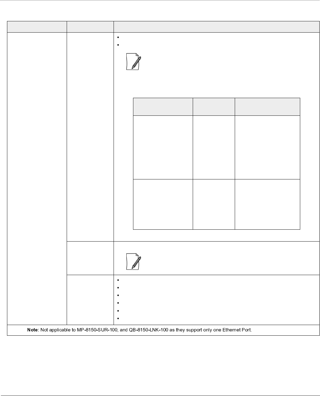
Technical Specifications
Tsunami® 800 and 8000 Series - Hardware Installation Guide 132
Power Supply
Products Category Specification
MP-8100-BSU
MP-8100-SUA
MP-8150-SUR
MP-8150-SUR-100
MP-8200-BSU
MP-8250-BS9
MP-8250-BS1
MP-8200-SUA
MP-8250-SUR
QB-8100-EPA/LNK
QB-8150-EPR/LNK
QB-8150-LNK-100
QB-8151-EPR/LNK
QB-8200-EPA/LNK
QB-8250-EPR/LNK
Input Voltage Via RJ-45 Ethernet interface supplying 48 VDC and 0.67A on Ethernet Port#1
12 V-DC through RJ-11 serial port (for diagnostic purpose)
: Only one of the above input voltage options should be used at a time, to
power on the device. Combination of any two options, may damage the
device.
Tabulated below are the power consumption details.
Output Voltage* 48VDC through Ethernet Port #2. Power Always ON.
: Output voltage of 48VDC requires a 60-80W high power POE, available
with Proxim Wireless Corporation on request.
Power over
Ethernet Injector
Input: 100 – 250 V-AC (47 – 63 Hz)
Output: 48 V-DC at 0.67 A (32 Watts)
Pin-out: +48 V on pins 4/5, -48 V on pins 7/8
Size: 5.24x2.13x1.42 inches(133x54x36 mm)
Weight: 7 ounces (200 g)
Temp: 0 to 40º C
Products Typical
Consumption
Consumption (With
Heaters ON)
MP-8100-BSU
MP-8100-SUA
MP-8150-SUR
MP-8150-SUR-100
QB-8100-EPA/LNK
QB-8150-EPR/LNK
QB-8150-LNK-100
QB-8151-EPR/LNK
QB-8250-EPR/LNK
6 Watts 17 Watts maximum, with
two heaters ON
MP-8200-BSU
MP-8250-BS9
MP-8250-BS1
MP-8200-SUA
MP-8250-SUR
QB-8200-EPA/LNK
QB-8250-EPR/LNK
12 Watts 22 Watts maximum, with
two heaters ON
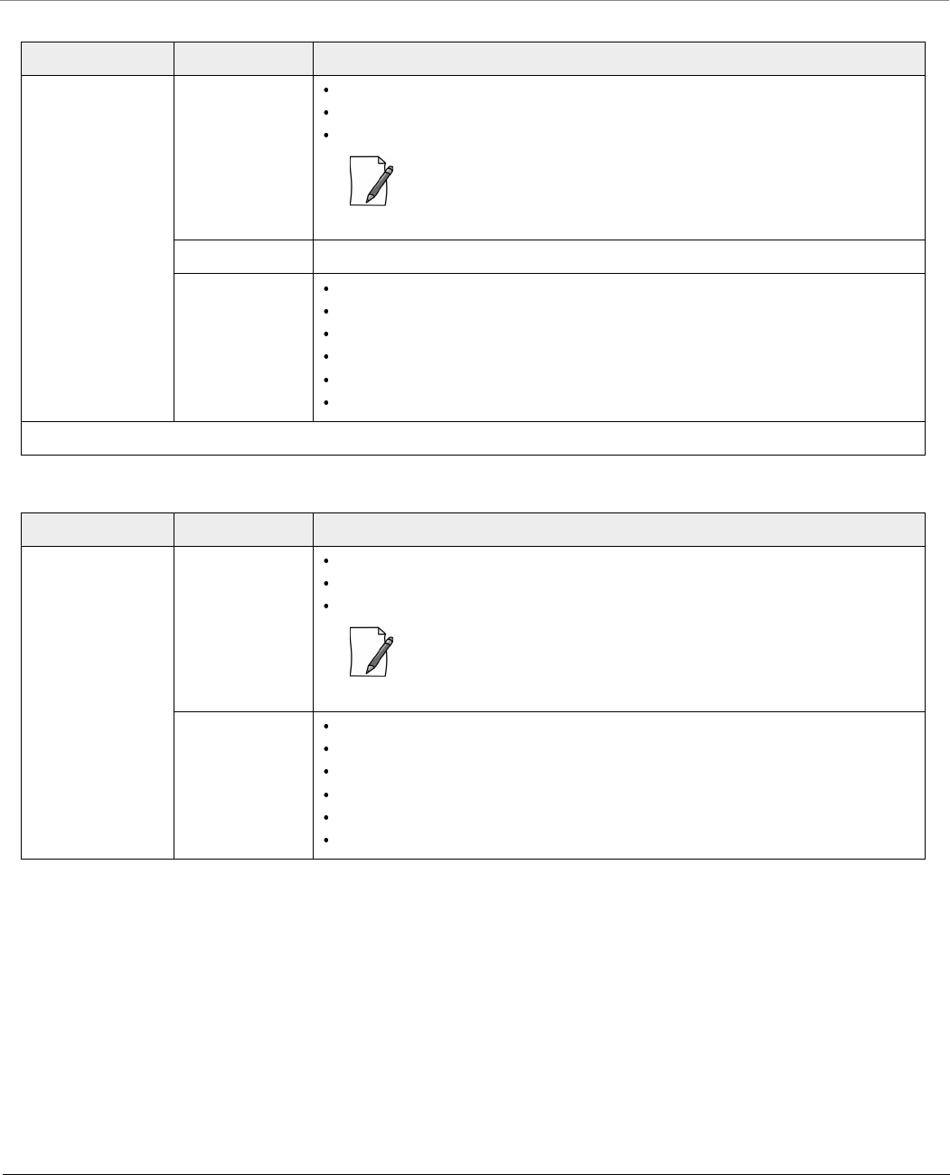
Technical Specifications
Tsunami® 800 and 8000 Series - Hardware Installation Guide 133
Products Category Specification
MP-8160-BSU
MP-8160-BS9
MP-8160-SUA
Input Voltage Via RJ-45 Ethernet interface supplying 48 VDC and 0.67 A on Ethernet Port#1
12 V-DC through serial port (for diagnostic purpose)
Consumption 10 Watts typical (13.8 Watts maximum with one heater ON)
: Only one of the above input voltage options should be used at a time, to
power on the device. Combination of any two options, may damage the
device.
Output Voltage* 48VDC through Ethernet Port #2. Power Always On.
Power over
Ethernet Injector
Input: 100 – 250 V-AC (47 – 63 Hz)
Output: 48 V-DC at 0.67 A (32 Watts)
Pin-out: +48 V on pins 4/5, -48 V on pins 7/8
Size: 5.24x2.13x1.42 inches(133x54x36 mm)
Weight: 7 ounces (200 g)
Temp: 0 to 40º C
Products Category Specification
MP-8150-CPE
QB-8150-LNK-12
QB-8150-LNK-50
Input Voltage Via RJ-45 Ethernet interface supplying 48 VDC and 0.40 A on Ethernet Port
12 V-DC through serial port (for diagnostic purpose)
Consumption 7 Watts typical (13.8 Watts maximum)
: Only one of the above input voltage options should be used at a time, to
power on the device. Combination of any two options, may damage the
device.
PoE Injector Input: 100 – 250 V-AC (47 – 63 Hz)
Output: 48 V-DC at 0.40 A (19 Watts)
Pin-out: +48 V on pins 4/5, -48 V on pins 7/8
Size: 3.98 x 2.40 x 1.35 inches (101.0x61.5x32.2 mm)
Weight: 5.6 ounces (160 g)
Temp: 0 to 40º C

Technical Specifications
Tsunami® 800 and 8000 Series - Hardware Installation Guide 134
Products Category Specification
MP-826-CPE-50 Input Voltage Via RJ-45 Ethernet interface supplying 48 VDC and 0.40A on Ethernet Port
Consumption of 10 Watts typical (18 Watts max with one heater ON)
PoE Injector Input: 100 – 250 V-AC (47 – 63 Hz)
Output: 48 V-DC at 0.40 A (19 Watts)
Pin-out: +48 V on pins 4/5, -48 V on pins 7/8
Size: 4.96 x 8.62 x 2.58 inches (126 x 219 x 65.5 mm)
Weight: 5.6 ounces (160 g)
Temp: 0 to 40º C
Products Category Specification
MP-8160-CPE-A100 Input Voltage Via RJ-45 Ethernet interface supplying 48 VDC and 0.40A on Ethernet Port
Consumption 5 Watts typical (10 Watts maximum)
PoE Injector Input: 100 – 250 V-AC (47 – 63 Hz)
Output: 48 V-DC at 0.40 A (19 Watts)
Pin-out: +48 V on pins 4/5, -48 V on pins 7/8
Size: 3.98 x 2.40 x 1.35 inches (101.0x61.5x32.2 mm)
Weight: 5.6 ounces (160 g)
Temp: 0 to 40º C
Products Category Specification
MP-825-CPE-50
MP-825-CPE-100
QB-825-EPR-50
Input Voltage Via RJ-45 Ethernet interface supplying 48 VDC and 0.40A on Ethernet Port
Consumption 6 Watts typical (15 Watts max with two heaters ON)
PoE Injector Input: 100 – 250 V-AC (47 – 63 Hz)
Output: 48 V-DC at 0.40 A (16 Watts)
Pin-out: +48 V on pins 4/5, -48 V on pins 7/8
Size: 3.98 x 2.40 x 1.35 inches (101.0x61.5x32.2 mm)
Weight: 5.6 ounces (160 g)
Temp: 0 to 40º C
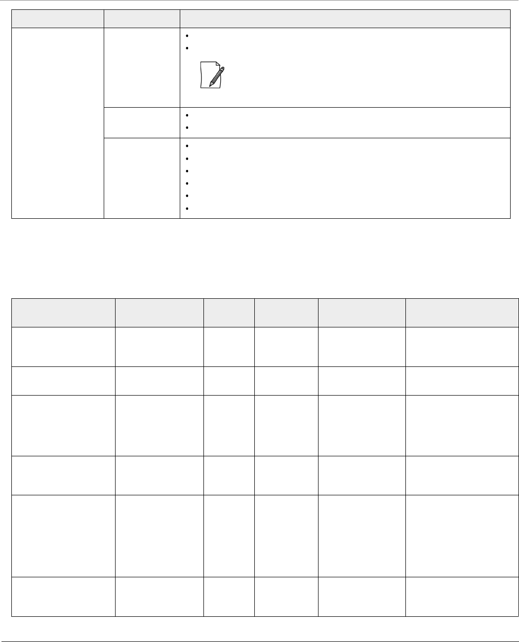
Technical Specifications
Tsunami® 800 and 8000 Series - Hardware Installation Guide 135
Hardware Specifications
Products Category Specification
MP-820-BSU-100
MP-820-SUA-50+
MP-825-SUR-50+
MP-825-BS3-100
QB-825-EPR/LNK-50+
Input Voltage Via RJ-45 Ethernet interface supplying 48 VDC and 0.67A on Ethernet Port#1
12 V-DC through RJ-11 serial port (for diagnostic purpose)
: Only one of the above input voltage options should be used at a time, to
power on the device. Combination of any two options, may damage the
device.
Power
Consumption
Typical Consumption: 6 Watts
Consumption (With Heaters ON): 16 Watts maximum, with two heaters ON
PoE Injector Input: 100 – 250 V-AC (47 – 63 Hz)
Output: 48 V-DC at 0.67 A (32 Watts)
Pin-out: +48 V on pins 4/5, -48 V on pins 7/8
Size: 5.24x2.13x1.42 inches(133x54x36 mm)
Weight: 7 ounces (200 g)
Temp: 0 to 40º C
Products Radio Clock
Speed
Memory Input Power Power Consumption
MP-8100-BSU
MP-8100-SUA
QB-8100-EPA
2.4 and 5 GHz
MIMO dual band
radio
680 MHz Flash: 16 MB
RAM: 128 MB
Power-over-Ethernet
48 VDC, 0.67 A
6 Watts typical (17 Watts
max with two heaters ON)
MP-8150-SUR
QB-8150-EPR
4.900 to 5.925 GHz
MIMO radio
680 MHz Flash: 16 MB
RAM: 128 MB
Power-over-Ethernet
48 VDC, 0.67 A
6 Watts typical (17 Watts
max with two heaters ON)
MP-820-BSU-100
MP-820-SUA-50+
MP-825-SUR-50+
MP-825-BS3-100
QB-825-EPR-50+
5.150 to 5.925 GHz
MIMO radio
560 MHz Flash: 16 MB
RAM: 128 MB
Power-over-Ethernet
48 VDC, 0.67 A
6 Watts typical (16 Watts
max with two heaters ON)
MP-8150-SUR-100
QB-8150-EPR-100
QB-8151-EPR
4.900 to 5.875 GHz
MIMO radio
680 MHz Flash: 16 MB
RAM: 128 MB
Power-over-Ethernet
48 VDC, 0.67 A
6 Watts typical (17 Watts
max with two heaters ON)
MP-8200-BSU
MP-8250-BS9
MP-8250-BS1
MP-8200-SUA
MP-8250-SUR
QB-8200-EPA
QB-8250-EPR
4.900 to 5.925 GHz
MIMO High Power
radio
680 MHz Flash: 16 MB
RAM: 128 MB
Power-over-Ethernet
48 VDC, 0.67 A
12 Watts typical (22 Watts
max with two heater ON)
MP-8160-BSU
MP-8160-BS9
MP-8160-SUA
5.900 to 6.425 GHz
MIMO radio
680 MHz Flash: 16 MB
RAM: 128 MB
Power-over-Ethernet
48 VDC, 0.67 A
10 Watts typical (13.8
Watts max with one heater
ON)

Technical Specifications
Tsunami® 800 and 8000 Series - Hardware Installation Guide 136
MP-8150-CPE
QB-8150-EPR-12
QB-8150-EPR-50
5.3 to 6.1GHz
MIMO radio
333 MHz 333 MHz Power-over-Ethernet
48 VDC, 0.40 A
7 Watts typical (13.8 Watts
max)
MP-8160-CPE-A100 5.900 to 6.425 GHz
MIMO radio
333 MHz Flash: 16 MB
RAM: 128 MB
Power-over-Ethernet
48 VDC, 0.40 A
5 Watts typical (10 Watts
max)
MP-825-CPE-50
MP-825-CPE-100
QB-825-EPR-50
5.15 to 5.925 GHz
MIMO radio
560 MHz Flash: 16 MB
RAM: 128 MB
Power-over-Ethernet
48 VDC, 0.4 A
6 Watts typical (15 Watts
max with two heaters ON)
MP-826-CPE-50 5.900 to 6.425 GHz
MIMO radio
560 MHz Flash: 16 MB
RAM: 128 MB
Power-over-Ethernet
48 VDC, 0.4 A
10 Watts typical (17 Watts
max with one heater ON)
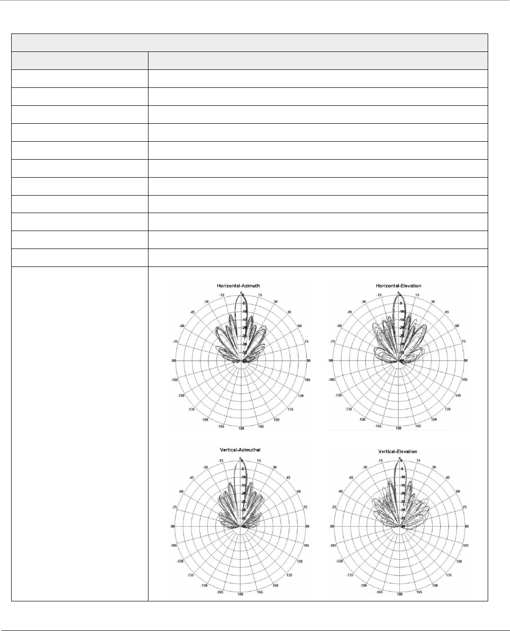
Technical Specifications
Tsunami® 800 and 8000 Series - Hardware Installation Guide 137
Integrated Antenna Specifications
Products: MP-8150-SUR; QB-8150-EPR/LNK; MP-8250-SUR; MP-8250-BS1; QB-8250-LNK
Feature Specification
Frequency Band 4.900 – 5.875 GHz
Gain 22 dBi (Cable loss included)
3dB Beamwidth 7º - 9º (Hplane)
3dB Beamwidth 7º - 9º (Eplane)
Polarization Dual (Vertical + Horizontal)
Cross Polarization -25 dB
Port to Port Isolation -30 dB
Power Handling 5 W (cw)
VSWR 1.7:1 Max
Standard Compliance ETSI TS3, TS4, TS5
Lightning Protection DC Ground
Radio Patterns

Technical Specifications
Tsunami® 800 and 8000 Series - Hardware Installation Guide 138
Antenna Tilt Angles and corresponding EIRP values:
: These values are applicable only to the devices operating in U-NII-1US frequency band (5.15 - 5.25GHz)
• -10 degree indicates that the antenna is tilted downwards
• 10 degrees indicates that the antenna is titled upwards
For detailed exlplanation of the various constituents in the table, please refer Antenna Installation guide > 1.2.3.2 Antenna
Tilt Angles and Corresponding EIRP values in the page number 12
Products: MP-8150-SUR; QB-8150-EPR/LNK; MP-8250-SUR; MP-8250-BS1; QB-8250-LNK
Tilt Angle Horizontal Side
Lobe
Vertical Side
Lobe
Allowed
Transmit Power
EIRP of Product Remarks
0 12 16 7 33
-10 12 16 7 33
-20 19 18 13 39
-30 19 19 14 40
10 12 14 7 33
20 10 13 5 31
30 0 0 -5 21 Not recommended
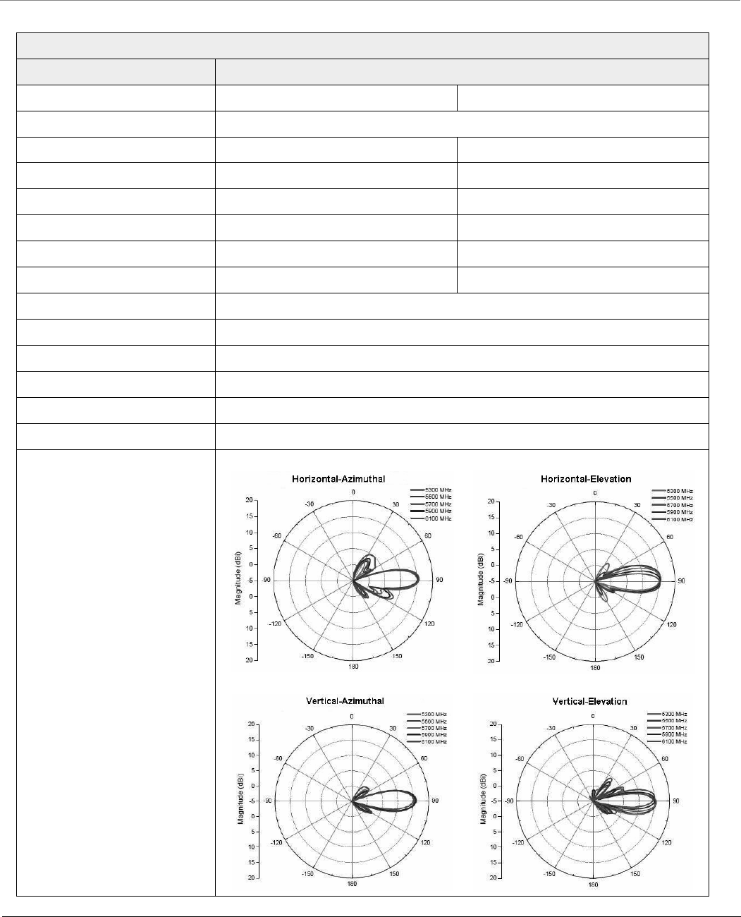
Technical Specifications
Tsunami® 800 and 8000 Series - Hardware Installation Guide 139
Products: MP-8150-CPE; QB-8150-LNK-12/50
Feature Specification
Vertical Polarization Horizontal Polarization
Frequency Band 5.300 – 6.100 GHz
Gain 15 - 16 dBi 15 - 16 dBi
Horizontal Half Power Beam Width 17.6o – 20.3o16.5o – 18.3o
Vertical Half Power Beam Width 16.1o - 20.5o 17.0o - 24.0o
Sidelobes Level -10 dB (Max) -8 dB (Max)
Front-to-back-ratio 23 dB (Max) -21 dB (Max)
Polarization Linear, Vertical Linear, Horizontal
Port to Port Isolation 27 dB (Min.)
Power Handling 6 W (cw)
VSWR 2.0:1 (Max)
Input Impedance 50 ohm
Standard Compliance ETSI TS3, TS4, TS5
Lightning Protection DC Ground
Radio Patterns
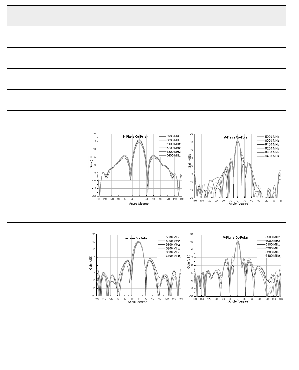
Technical Specifications
Tsunami® 800 and 8000 Series - Hardware Installation Guide 140
Product: MP-8160-CPE-A100, MP-826-CPE-50
Feature Specification
Frequency Range 5900 – 6400 MHz
Polarization Vertical/Horizontal
Gain 13.5-14.5 dBi / 14.0-15 dBi
Horizontal Half Power Beam Width 35º-40º / 25º-35º
Vertical Half Power Beam Width 15º- 18º
VSWR 2:1 (Max)
Isolation 25 dB (Min)
Input Impedance 50 ohm
Lightning Protection DC Ground
Radio Patterns (V-Polar Port)
Radio Patterns (H-Polar Port)
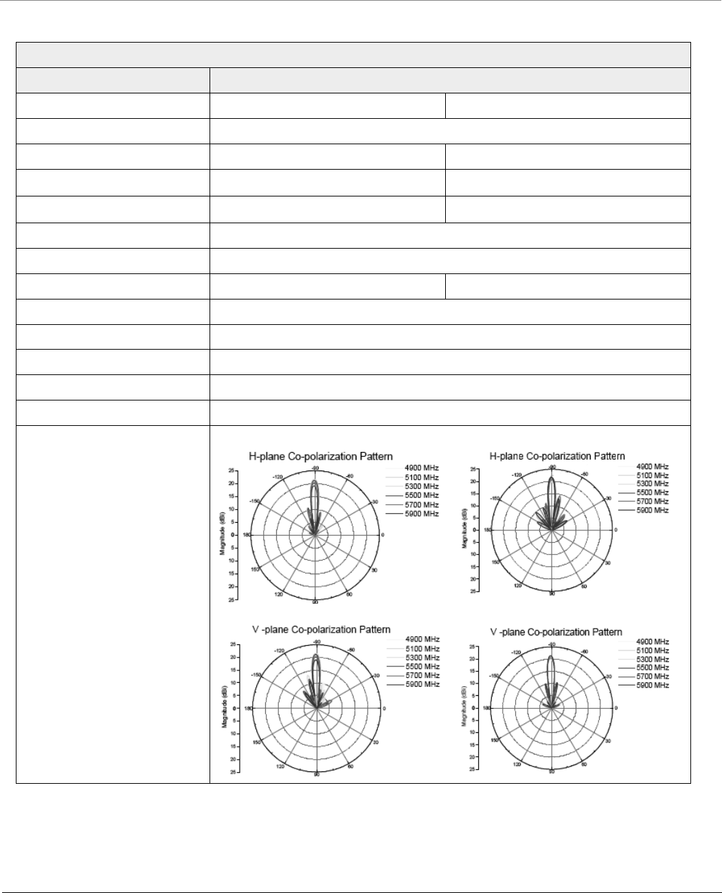
Technical Specifications
Tsunami® 800 and 8000 Series - Hardware Installation Guide 141
Products: MP-8150-SUR-100; QB-8151-EPR / LNK
Feature Specification
Vertical Polarization Horizontal Polarization
Frequency Band 4900 - 5875 MHz
Gain 20.0±1 dBi 21.0±1 dBi
Horizontal Half Power Beam Width 8o (typ.)
Vertical Half Power Beam Width 8o (typ.)
Sidelobes Level -8 dB (Max)
Front-to-back-ratio -30 dB (Max)
Polarization Linear, Vertical Linear, Horizontal
Isolation 25 dB (min.)
Power Handling 2W (cw)
VSWR 2.0: 1 (Max)
Input Impedance 50 ohm
Lightning Protection DC Ground
Radio Patterns

Technical Specifications
Tsunami® 800 and 8000 Series - Hardware Installation Guide 142
Antenna Tilt Angles and corresponding EIRP values:
: These values are applicable only to the devices operating in U-NII-1US frequency band (5.15 - 5.25GHz)
Products: MP-8150-SUR-100; QB-8151-EPR / LNK
Tilt Angle Horizontal Side
Lobe
Vertical Side
Lobe
Allowed
Transmit Power
EIRP of Product Remarks
0 13 13 10 34
-10 13 14 10 34
-20 14 14 11 35
-30 14 14 11 35
10 13 11 8 32
20 7 10 4 28
30 0 0 -3 21 Not recommended
Products: MP-8160-BS9
Feature Specification
Frequency Range 5.7 - 6.425 GHz
Polarization Dual, Vertical and Horizontal
Gain 16 dBi
VSWR, max. 1.7:1
3.5 dB Beam-Width, H-Plane 90º
3 dB Beam-Width, E-Plane 8.5º
Side Lobes, min. -25 dB (azimuth)
Cross Polarization, min. -18 dB
Port to Port Isolation -45 dB
Front to Back Ratio, min. -40 dB
Input Power, max 10 Watt
Input Impedance 50 Ohm
Lightning Protection DC Grounded
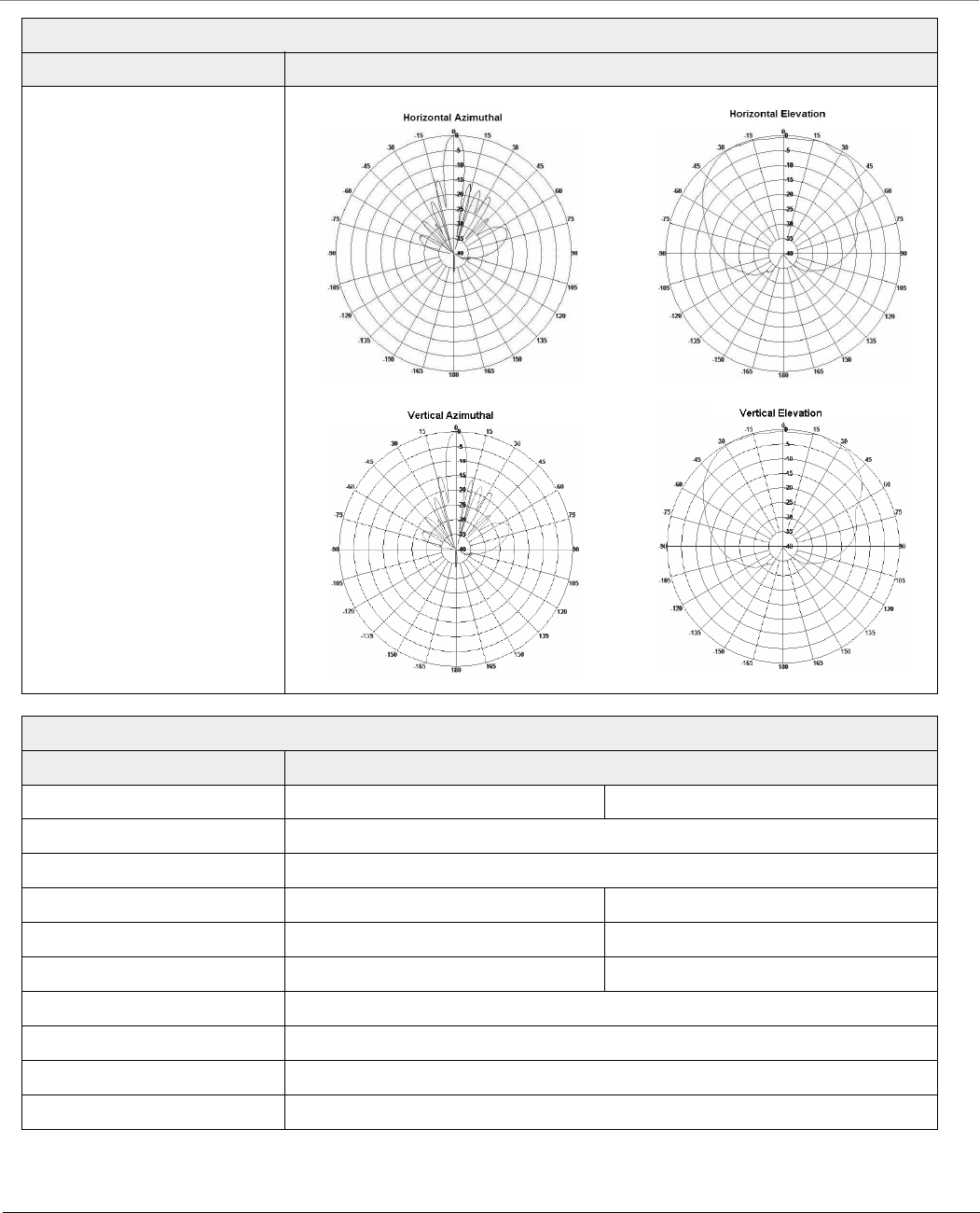
Technical Specifications
Tsunami® 800 and 8000 Series - Hardware Installation Guide 143
Radio Patterns
MP-825-CPE-50, MP-825-CPE-100, MP-825-SUR-50+, MP-825-BS3-100, QB-825-LNK-50, and QB-825-LNK-50+
Feature Specification
Vertical Polarization Horizontal Polarization
Frequency Band 5.15 - 5.925 MHz
Gain 15 - 16 dBi (14 dBi beyond 5.850 GHz)
Horizontal Half Power Beam Width 31o – 38o30o – 34o
Vertical Half Power Beam Width 14o - 16o 14o - 17o
Sidelobes Level 12 dB (Min) 10 dB (Min)
Polarization Dual, Vertical and Horizontal
Isolation > 30 dB typl.
VSWR < 2.0:1 (Max)
Lightning Protection DC Grounded
Products: MP-8160-BS9
Feature Specification
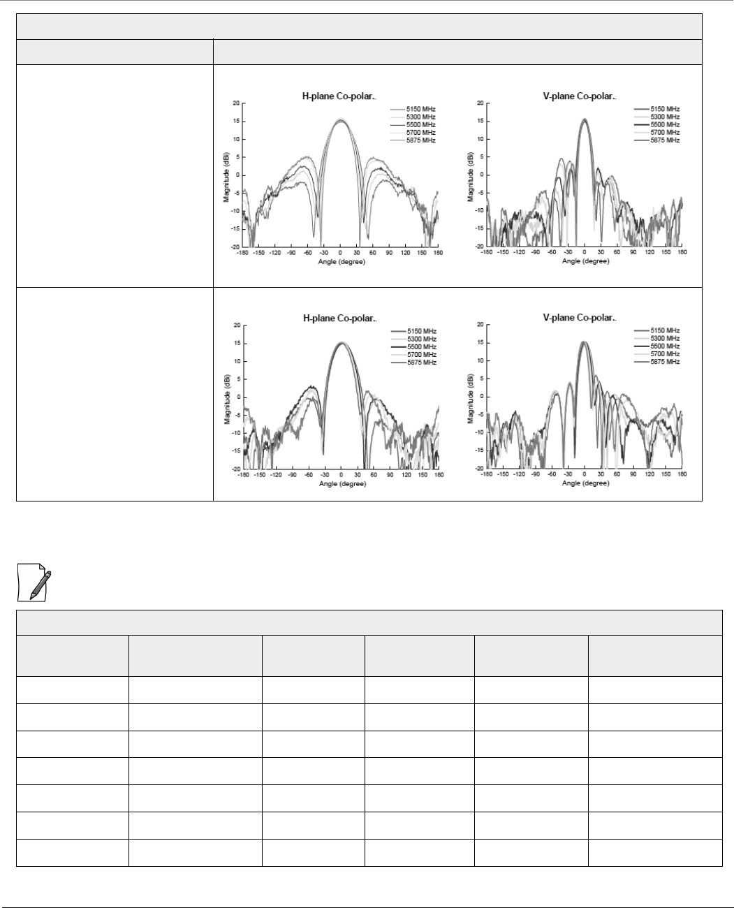
Technical Specifications
Tsunami® 800 and 8000 Series - Hardware Installation Guide 144
Antenna Tilt Angles and corresponding EIRP values:
: These values are applicable only to the devices operating in U-NII-1US frequency band (5.15 - 5.25GHz)
Radio Patterns (V-Polar Port)
Radio Patterns (H-Polar Port)
MP-825-CPE-50, MP-825-CPE-100, MP-825-SUR-50+, MP-825-BS3-100, QB-825-LNK-50, and QB-825-LNK-50+
Tilt Angle Horizontal Side
Lobe
Vertical Side
Lobe
Allowed
Transmit Power
EIRP of Product Remarks
0 9 13 11 30
-10 13 16 15 34
-20 13 16 15 34
-30 13 20 15 34
10 8 13 10 29
20 0 0 2 21
30 0 0 2 21
MP-825-CPE-50, MP-825-CPE-100, MP-825-SUR-50+, MP-825-BS3-100, QB-825-LNK-50, and QB-825-LNK-50+
Feature Specification
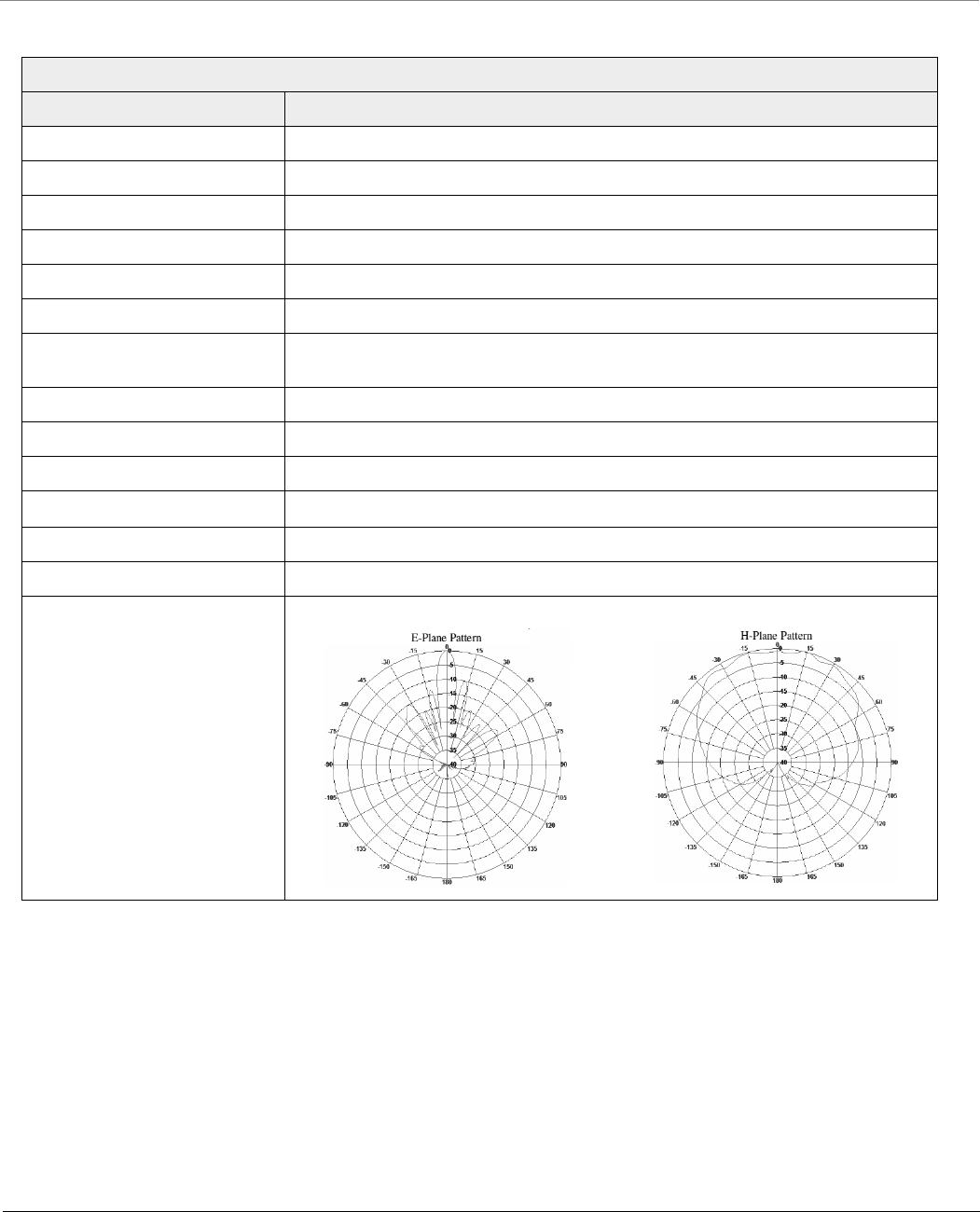
Technical Specifications
Tsunami® 800 and 8000 Series - Hardware Installation Guide 145
Products: MP-8250-BS9
Feature Specification
Frequency Band 4.9 – 6.1 MHz
Gain, typ. 16 dBi
VSWR, Max. 1.7:1
Polarization Dual Pol., Vertical and Horizontal
3 dB Beam-Width, H-Plane, typ. 90o
3 dB Beam-Width, E-Plane, typ. 8o
Sidelobes Level, Min. V-Pol: ETSI EN 302 085 V1.2.3 – CS2
H-Pol: ETSI EN 302 085 V1.2.3 – CS3
Cross Polarization, min. -15 dB
Front to Back Ratio, min. -30 dB
Port to Port Isolation, min. -30 dB
Input power, max 10 Watt
Input Impedance 50 Ohm
Lightning Protection DC Grounded
Radio Patterns (V-Polar Port)
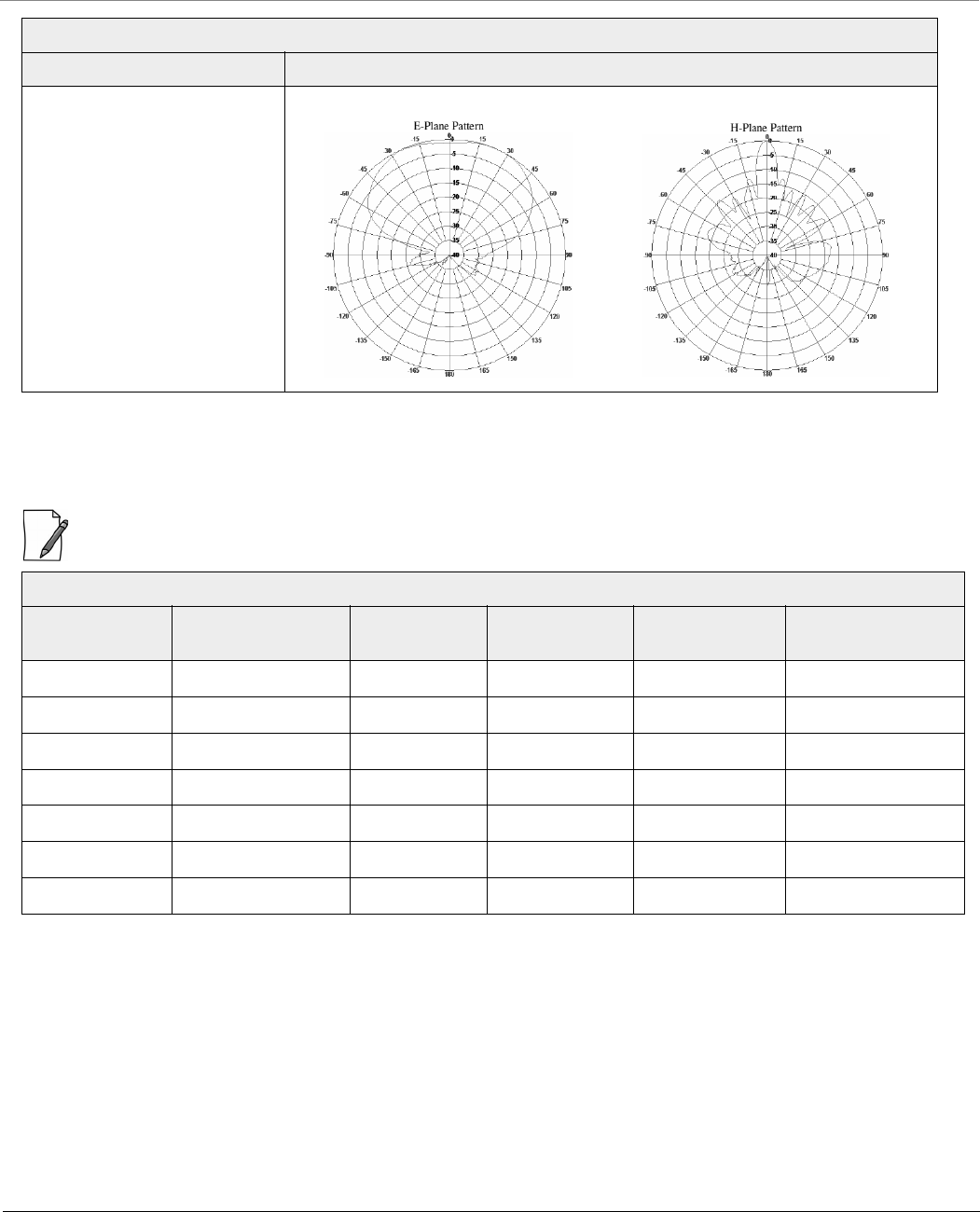
Technical Specifications
Tsunami® 800 and 8000 Series - Hardware Installation Guide 146
Antenna Tilt Angles and corresponding EIRP values:
: These values are applicable only to the devices operating in U-NII-1US frequency band (5.15 - 5.25GHz)
Radio Patterns (H-Polar Port)
Products: Products: MP-8250-BS9
Tilt Angle Horizontal Side
Lobe
Vertical Side
Lobe
Allowed
Transmit Power
EIRP of Product Remarks
0 16 18 18 37
-10 17 18 19 38
-20 17 18 19 38
-30 17 20 19 38
10 17 18 19 38
20 13 10 12 31
30 0 0 2 21
Products: MP-8250-BS9
Feature Specification

Technical Specifications
Tsunami® 800 and 8000 Series - Hardware Installation Guide 147
Physical Specifications
Products Category Specification
MP-8100-BSU,
MP-8100-SUA
QB-8100-EPA
Dimensions (L x W x H) 10.79 x 11.14 x 3.38 inches (274 x 283 x 86 mm)
Weight 7.7 lbs (3.5 kg)
MP-8150-SUR
QB-8150-EPR
Dimensions (L x W x H) 14.57 x 14.57 x 4.47 inches (370 x 370 x 113.5 mm)
Weight 9.0 lbs (4.1 kg)
MP-8150-SUR-100
QB-8150-EPR-100
QB-8151-EPR
Dimensions (L x W x H) 14.57 x 14.57 x 4.21 inches (370 x 370 x 107 mm)
Weight 8.45 lbs (3.85 kg)
MP-8200-BSU
MP-8200-SUA
QB-8200-EPA
Dimensions (L x W x H) 10.79 x 11.14 x 3.38 inches (274 x 283 x 86 mm)
Weight 7.9 lbs (3.6 kg)
MP-8250-SUR
MP-8250-BS9
MP-8250-BS1
QB-8250-EPR
Dimensions (L x W x H) 14.57 x 14.57 x 4.47 inches (370 x 370 x 113.5 mm)
Weight 9.26 lbs (4.2 kg)
MP-8160-BSU
MP-8160-SUA
Dimensions (L x W x H) 10.79 x 11.14 x 3.38 inches (274 x 283 x 86 mm)
Weight 7.38 lbs (3.35 kg)
MP-8160-BS9 Dimensions (L x W x H) 14.57 x 14.57 x 4.47 in (370 x 370 x 113.5 mm)
Weight 8.82 lbs (4 kg)
MP-8150-CPE Dimensions (L x W x H) 7.77 x 7.56 x 3.94 inches (197.5 x 192 x 100mm)
Weight 1.6 lbs (0.73 kg)
MP-8160-CPE-A100 Dimensions (L x W x H) 8.46 x 4.78 x 2.56 inches (215 x 121.5 x 65 mm)
Weight 1.93 lbs (0.88 kg)
MP-820-BSU-100
MP-820-SUA-50+Dimensions (L x W x H) 5.02 x 8.68 x 2.85 inches (127.5 x 220.5 x 72.5 mm)
Weight 2.75 lbs (1.250 kg)
MP-826-CPE-50
MP-825-CPE-50
MP-825-CPE-100
MP-825-SUR-50+
MP-825-BS3-100
QB-825-EPR-50
QB-825-EPR-50+
Dimensions (L x W x H) 4.96 x 8.62 x 2.58 inches (126 x 219 x 65.5 mm)
Weight 2.1 lbs (0.95 kg)
QB-8150-EPR-12
QB-8150-EPR-50
Dimensions (L x W x H) 7.77 x 7.56 x 3.94 inches (197.5 x 192 x 100mm)
Weight 1.6 lbs (0.73 kg)

Technical Specifications
Tsunami® 800 and 8000 Series - Hardware Installation Guide 148
Environmental Specifications
Products Operating Temperature Storage Temperature Humidity
MP-8100-BSU; MP-8100-SUA
MP-8150-SUR; MP-8150-SUR-100
MP-8200-BSU; MP-8200-SUA
MP-8250-SUR; MP-8160-BSU
MP-8160-BS9; MP-8160-SUA
MP-8250-BS9; MP-8250-BS1
QB-8100-EPA/LNK; QB-8150-EPR/LNK
QB-8150-LNK-100; QB-8151-EPR/LNK
QB-8200-EPA/LNK; QB-8250-EPR/LNK
-40º to 60ºC
(-40º to 140º Fahrenheit)
-55º to 80ºC
(-67º to 176º Fahrenheit)
100% (non-condensing)
MP-8150-CPE
QB-8150-LNK-12/50
-35º to 55ºC
(-31º to 131º Fahrenheit)
-40º to 70ºC
(-40º to 158º Fahrenheit)
Max 95% relative humidity
(non-condensing)
MP-8160-CPE-A100 -40° to 55°C
(-40° to 131° Fahrenheit)
-45º to 70ºC
(-49º to 158º Fahrenheit)
Max 95% relative humidity
(non-condensing)
MP-826-CPE-50
MP-825-CPE-50
MP-825-CPE-100
MP-820-BSU-100
MP-820-SUA-50+
MP-825-SUR-50+
MP-825-BS3-100
QB-825-EPR/LNK-50+
QB-825-EPR/LNK-50
-40º to 55ºC (-40º to 131º
Fahrenheit)
-55º to 70ºC (-67º to 158º
Fahrenheit)
100% (non-condensing)

Technical Specifications
Tsunami® 800 and 8000 Series - Hardware Installation Guide 149
MTBF
Products MTBF
MP-8100-BSU
MP-8100-SUA
MP-8150-SUR
MP-8150-SUR-100
MP-8160-BSU
MP-8160-BS9
MP-8160-SUA
QB-8100-EPA/LNK
QB-8150-EPR/LNK
QB-8150-LNK-100
QB-8151-EPR/LNK
>80,000 hours
MP-8150-CPE
MP-8160-CPE-A100
QB-8150-LNK-12/50
75,000 hours
MP-826-CPE-50 >2,00,000 hours
MP-8200-BSU
MP-8250-BS9
MP-8250-BS1
MP-8200-SUA
MP-8250-SUR
QB-8200-EPA/LNK
QB-8250-EPR/LNK
>250,000 hours
MP-820-BSU-100
MP-820-SUA-50+
MP-825-SUR-50+
MP-825-BS3-100
MP-825-CPE-50
MP-825-CPE-100
QB-825-EPR/LNK-50
QB-825-EPR/LNK-50+
>350,000 hours
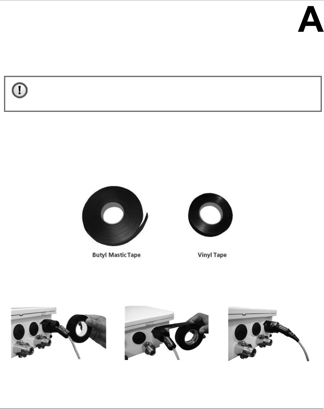
Tsunami® 800 and 8000 Series - Hardware Installation Guide 150
Appendix - Additional Weatherproofing Steps
This chapter explains the method to add an additional layer of protection to the connectors (Ethernet) against the
environment.
A.1 Material for Weatherproofing
The material required for weatherproofing connectors are,
1. Any standard Butyl Mastic Tape
2. Any standard Vinyl Tape
We have used the following Butyl Mastic Tape and Vinyl Tape as an example to demonstrate the weatherproofing steps:
A.2 Weatherproofing Steps
1. Wrap a vinyl tape in a half-lapped fashion, from the weatherproofed connector end and continue wrapping till 3
inches onto the cable.
Figure A-1 Step1
: We have taken MP-8100-BSU as an example to explain the weatherproofing steps. The same method
should be followed to weatherproof the Ethernet connectors of the Tsunami® 800 and 8000 series
products.
(a) (b) (c)
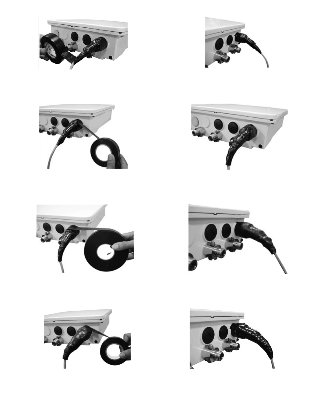
Appendix - Additional Weatherproofing Steps
Tsunami® 800 and 8000 Series - Hardware Installation Guide 151
2. Wrap a second layer of the vinyl tape over the first layer but in other direction.
Figure A-2 Step2
3. Now, wrap a layer of vinyl tape with the adhesive side out as it provides sticky surface for the next layer.
Figure A-3 Step3
4. Next, wrap a layer of the butyl mastic tape on the adhesive side.
Figure A-4 Step3
5. Finally, wrap vinyl tap over the butyl layer.
Figure A-5 Step3
(a) (b)
(a) (b)
(a) (b)
(a) (b)

Tsunami® 800 and 8000 Series - Hardware Installation Guide 152
Appendix - Lightning Protection
Lightning protection is used to maximize the reliability of the communications equipment by safely re-directing current from
a lightning strike or a power surge traveling along the Cat 5/Cat5e/Cat 6 Ethernet cabling to the ground using the shortest
path possible. Designing a proper grounding system prior to installing any communications equipment is critical to minimize
the possibility of equipment damage, void warranties, and cause serious injury.
The surge arrestor (sometimes referred to as a lightning protector) can protect your sensitive electronic equipment from
high-voltage surges caused by discharges and transients at the PoE.
Proxim Wireless offers superior lightning and surge protection for Tsunami® series products. Contact your reseller or
distributor for more information.

Tsunami® 800 and 8000 Series - Hardware Installation Guide 153
Appendix - Abbreviations
Abbreviations
AWG American Wire Gauge
BSU Base Station Unit
CLI Command Line Interface
CPE Customer Premises Equipment
DC Direct Current
ESD Electrostatic Discharge
FCS Frame Check Sequence
LED Light Emitting Diode
MIMO Multiple-input and Multiple-output
MTBF Mean Time Between Failures
OFDM Orthogonal frequency-division multiplexing
PC Personal Computer
PoE Power Over Ethernet
PTMP Point-to-multipoint
PTP Point-to-point
QB Quick Bridge
QIG Quick Installation Guide
RSSI Received Signal Strength Indicator
Rx Receiver
SU Subscriber Unit
Tx Transmission
WORP Wireless Outdoor Router Protocol

Tsunami® 800 and 8000 Series - Hardware Installation Guide 154
Appendix - Statement of Warranty
Warranty Coverage
Proxim Wireless Corporation warrants that its products are manufactured solely from new parts, conform substantially to
specifications, and will be free of defects in material and workmanship for a Warranty Period of 1 year from the date of
purchase.
Repair or Replacement
When Proxim determines that a returned product does not meet the warranted criteria during the warranty period, Proxim at
its option, will either: (a) repair the defective product; (b) replace the defective product with a new or refurbished product
that is at least equivalent to the original; or (c) refund the price paid for the defective product. Generally, products are
repaired or replaced within thirty (30) business days of receipt of the product at a Proxim Logistical/Repair Center. The
warranty period for repaired or replacement products is ninety (90) days or the remainder of the original warranty period,
whichever is longer. These three alternatives constitute the customer’s sole and exclusive remedy and Proxim’s sole and
exclusive liability under warranty provisions.
Limitations of Warranty
Proxim’s warranties do not apply to any product (hardware or software) which has (a) been subjected to abuse, misuse,
neglect, accident, or mishandling, (b) been opened, repaired, modified, or altered by anyone other than Proxim, (c) been
used for or subjected to applications, environments, or physical or electrical stress or conditions other than as intended and
recommended by Proxim, (d) been improperly stored, transported, installed, or used, or (e) had its serial number or other
identification markings altered or removed.
Buyers can contact Proxim Wireless Customer Service Center either by telephone or via web. Support and repair of products
that are out of warranty will be subject to a fee. Contact information is shown below. Additional support information can be
found at Proxim Wireless’s web site at .
Contact technical support via telephone as follows:
USA and Canada Customers
Phone: +1-408-383-7700; +1-866-674-6626
Business Hours: 24x7 live response. Tier 3 support: 8 a.m. to 5 p.m. M-F PDT (UTC/GMT -7 hrs)
International Customers
Phone: +1-408-383-7700; 0800-916475 (France); 8-800-100-9485 (Russia)
Business Hours: 24x7 live response. Tier 3 support: 8 a.m. to 5 p.m. M-F PDT (UTC/GMT -7 hrs)

Appendix - Statement of Warranty
Tsunami® 800 and 8000 Series - Hardware Installation Guide 155
General Procedures
When contacting the Customer Service for support, Buyer should be prepared to provide the product description and serial
number and a description of the problem. The serial number should be on the product.
In the event the Customer Service Center determines that the problem can be corrected with a software update, Buyer might
be instructed to download the update from Proxim Wireless’s web site or, if that’s not possible, the update will be sent to
Buyer. In the event the Customer Service Center instructs Buyer to return the product to Proxim Wireless for repair or
replacement, the Customer Service Center will provide Buyer a Return Material Authorization (“RMA”) number and shipping
instructions. Buyer must return the defective product to Proxim Wireless, properly packaged to prevent damage, shipping
prepaid, with the RMA number prominently displayed on the outside of the container.
Calls to the Customer Service Center for reasons other than product failure will not be accepted unless Buyer has purchased a
Proxim Wireless Service Contract or the call is made within the warranty period. After the warranty period, Technical Support
is fee based (detailed in ).
If Proxim Wireless reasonably determines that a returned product is not defective or is not covered by the terms of this
Warranty, Buyer shall be charged a service charge and return shipping charges.
Other Information
Search Knowledgebase
Proxim Wireless stores all resolved problems in a solution database at the following URL: .
Create a Support Request
Create a support request with Proxim Wireless technical support staff at the following URL:
.

Tsunami® 800 and 8000 Series - Hardware Installation Guide 156
Appendix - Technical Services and Support
Obtaining Technical Service and Support
If you are having trouble using the Proxim product, please read this manual and the additional documentation provided with
your product. If you require additional support to resolve your issue, please be ready to provide the following information
before you contact Proxim’s Technical Services team:
Product information
– Part number and serial number of the suspected faulty device
Trouble/error information
– Trouble/symptom being experienced
– Activities completed to confirm fault
– Network information (What kind of network are you using?)
– Circumstances that preceded or led up to the error
– Message or alarms viewed
– Steps taken to reproduce the problem
ServPak information (if a Servpak customer):
– ServPak account number
Registration information
– If the product is not registered, date and location where you purchased the product
: Technical Support is free for the warranty period from the date of purchase.
Support Options
Proxim eService Web Site Support
The Proxim eService Web site is available 7x24x365 at .
On the Proxim eService Web Site, you can access the following services:
Product Download Page: Provides quick links to product firmware, software, and documentation downloads.
Proxim TV Links: A link to helpful video tutorials.
Knowledgebase: A solution database of all the resolved problems. You can search by product, category, keywords,
or phrases.
Live Chat: Chat with a support technician on-line or request to call back at a later time.
Create a Support Request: Create a support request with our technical support staff who will reply to you by email.
Case Management: Login to check the status of your support cases, update your personal profile, or access
restricted information and features.
Provide Feedback: Submit a suggestion, complaint, or other feedback about the support site and our products.

Appendix - Technical Services and Support
Tsunami® 800 and 8000 Series - Hardware Installation Guide 157
Telephone Support
Contact technical support via telephone as follows:
USA and Canada Customers
Phone: +1-408-383-7700; +1-866-674-6626
Business Hours: 24x7 live response. Tier 3 support: 8 a.m. to 5 p.m. M-F PDT (UTC/GMT -7 hrs)
International Customers
Phone: +1-408-383-7700; 0800-916475 (France); 8-800-100-9485 (Russia)
Business Hours: 24x7 live response. Tier 3 support: 8 a.m. to 5 p.m. M-F PDT (UTC/GMT -7 hrs)
ServPak Support
To provide even greater investment protection, Proxim Wireless offers a cost-effective support program called ServPak.
ServPak is a program of enhanced service support options that can be purchased as a bundle or individually, tailored to meet
your specific needs. Whether your requirement is round the clock technical support or advance replacement service, we are
confident that the level of support provided in every service in our portfolio will exceed your expectations.
All ServPak service bundles are sold as service contracts that provide coverage for specific products from 1 to 3 years. Servpak
bundles are considered an upgrade to the standard product warranty and not an extension.
24x7 Basic Technical
Support
Basic Advanced
Replacement
(Two business days/
International economy
shipment service)
Priority Advanced
Replacement
(Next business day/
International priority
shipment service)
Priority Comprehensive
Advance Replacement
(Next business day/
International priority
shipment service)
8x7 Advanced Technical
Support
24x7 Advanced Technical
Support
24x7 Advanced Technical
Support
Software Maintenance PVES & PV NMS
Support
PVES & PV NMS
Support
Access to Knowledge
Base
Post-Installation
Optimization
50% discount on Onsite
Technical Support and
Services

Appendix - Technical Services and Support
Tsunami® 800 and 8000 Series - Hardware Installation Guide 158
Additional Information on ServPak Options
Advanced Replacement of Hardware
In the event of a hardware failure, our guaranteed turnaround time for return to factory repair is 30 days or less. Customers
who purchase this service are guaranteed replacement of refurbished or new hardware to be shipped out within one or two
business days, as applicable. Options are available for shipment services depending on the customer’s support needs.
Hardware is shipped on business days, Monday – Friday excluding Holidays, 8:00 AM – 3:30 PM Eastern Time.
Comprehensive Advanced Replacement of Hardware
In addition to ServPak Prime options, in the event of a hardware failure, Proxim will repair or replace the failed product for any
reason, other than vandalism.
7x24x365 Availability
Unlimited, direct access to technical support engineers 24 hours a day, 7 days a week, 365 days a year including Holidays.
8x5 Availability
Unlimited, direct access to world-class technical support engineers 8 hours a day, 5 days a week, Monday through Friday from
8:00AM - 5:00PM Pacific Standard Time.
Basic Technical Support
Customers who purchase this service can be rest assured that their call will be answered by Proxim’s Tier 1 technical support
and a case opened immediately to document the problem and provide initial troubleshooting to identify the solution and
resolve the incident in a timely manner.
Advanced Technical Support
In addition to Proxim’s world-class Tier 1 technical support, customers will be able to have their more complex issues escalated
to our world-class Tier 3 technical support engineers. Our Tier 3 engineers will review specific configurations to troubleshoot
intricate issues and will also provide helpful insights regarding Proxim’s products and various tips from decades of collective
experience in the wireless industry.
Software Maintenance
It's important to maintain and enhance security and performance of wireless equipment and Proxim makes this easy by
providing a Software Maintenance program that enables customers to access new feature and functionality rich software
upgrades and updates. Customers will also have full access to Proxim's vast Knowledgebase of technical bulletins, white
papers and troubleshooting documents.
Post-Installation Optimization
You can consult with our technical support engineers to enhance performance and efficiency of your network.
Post-installation optimization services include:
Review frequencies to select best possible channel
Review Modulation, Channel Bandwidth, MIMO, and WORP settings to optimize throughput and link quality
Review Satellite Density & TPC/ATPC settings
Assistance with Bandwidth controls

Appendix - Technical Services and Support
Tsunami® 800 and 8000 Series - Hardware Installation Guide 159
Assistance with QoS, RADIUS, and VLAN settings on Proxim equipment
To purchase ServPak support services, please contact your authorized Proxim distributor. To receive more information or for
questions on any of the available ServPak support options, please visit our website at
, call Proxim Support (For telephone numbers, see ) or send an
email to .
Technical Support Policy
Technical Support for Current Products during Warranty Period
All Customers are entitled to free technical support for the Proxim products they purchase from Proxim’s authorized resellers
or distributors. Technical Support is defined as communication via the Proxim Support website ( ) and/or
via telephone. This technical support will be provided for free for the entire time the product is covered by a Proxim
warranty.The term of Proxim’s warranty is determined according to the agreement under which the product was sold and
generally varies from 3 months to 2 years depending on the product. If a Customer disagrees with Proxim’s determination of
warranty duration, a request for review supported by a copy of all product purchase documentation may be submitted.
Technical Support for Current Products after Warranty Period
After the warranty period, technical support on products then being sold by Proxim will be based upon one of the following
three options Customers can choose:
Customers can choose to purchase one of Proxim’s ServPak extended warranty and enhanced support packages for
the product
Customers can choose to purchase one-time per-incident technical support for the product for a fee
Customers can choose to call the reseller or distributor who sold them the product for technical support
Tech Support on Discontinued Products
Technical Support on some products that Proxim has declared as EOL (End of Life) or otherwise is no longer selling is available
based upon one of the following three options Customers can choose:
For some discontinued products, Customers can choose to purchase one of Proxim’s EOL ServPak support packages
for the product
– No EOL ServPak support package will be available for any product discontinued more than 5 years ago
– No EOL ServPak support package is available for certain discontinued products
Customers can choose to purchase one-time per-incident technical support for the product on a per hour basis at a
rate of $125 an hour (4 hours minimum payable in advance by major credit card). This fee is payable in addition to any
RMA fee that may be charged to subsequently repair the product.
Customers can choose to call the reseller or distributor who sold them the product for technical support
All Proxim technical support for discontinued products, whether through an EOL ServPak package or otherwise, is provided
on a “best effort” basis and is subject to the continued availability of necessary components, equipment, and other technical
resources.
Note that Proxim is unable to support or warrant any equipment that has been modified, whether this modification is
physical, or if third-party software codes have been loaded onto the product.