Proxim Wireless S58-B60C Unlicensed Spread Spectrum Transceiver User Manual Backing down from TNG CCI 2
Proxim Wireless Corporation Unlicensed Spread Spectrum Transceiver Backing down from TNG CCI 2
Contents
- 1. Antenna Installation Manual
- 2. Installation Manual 1
- 3. Installation Manual 2
- 4. Installation Manual 3
Installation Manual 2
Tsunami Multipoint Version 1.3 Installation Guide
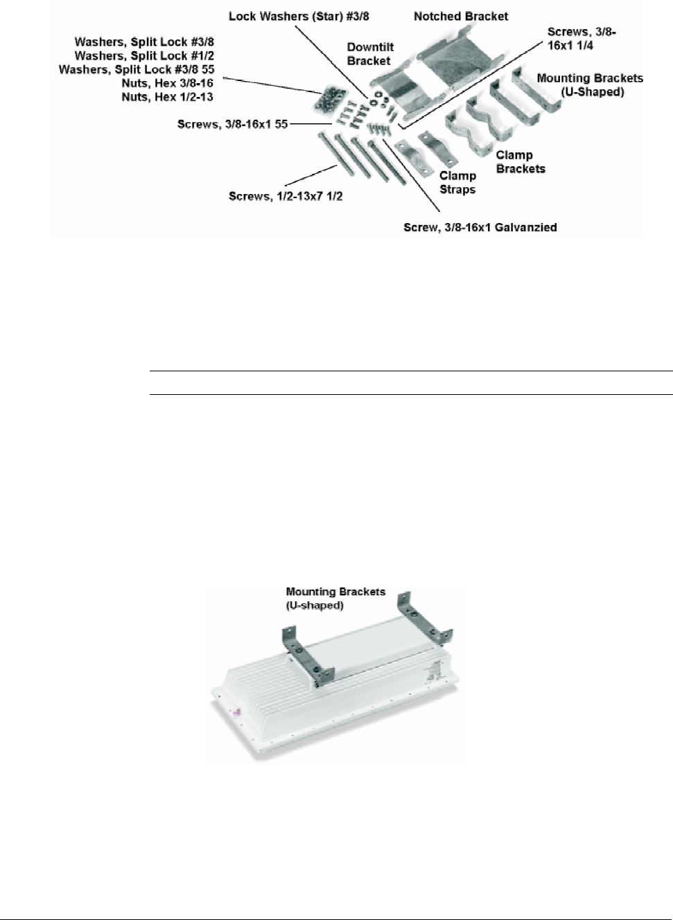
Figure 7. BSU Mounting Hardware
Required Tools: 9/16” (14-23 mm) wrench
6” (155 mm) crescent wrench
Note: Torque all #3/8 bolts and nuts 250 ± 10 in-lbs.
BSU Mounting: Ground Work
To assemble the BSU’s mounting components:
1. Place the BSU face (transmitter side) down on a flat surface.
2. Attach the two (u-shaped) galvanized mounting brackets to the back of the BSU using the four
stainless steel 3/8-16, hex head screws and four #3/8 split lock washers (see the following photo).
Figure 8. U-Shaped Mounting Brackets Attached
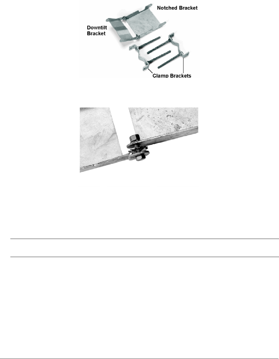
3. Insert two 1/2-13x7 1/2 screws through one of the clamp brackets (m-shaped) and secure the bolts
using two 1/2-13 hex nuts. Repeat this step for the other set of 1/2-13x7 1/2 screws, clamp bracket,
and 1/2-13 hex nuts (see Figure 9).
Chapter 2. Pre-Installation Tasks 18
CPN 63179 Issue Date: 01/24/03
Tsunami Multipoint Version 1.3 Installation Guide
4. Connect the downtilt bracket to the notched bracket using two 3/8-16x1 1/4 hex head screws, #3/8
split lock washers, #3/8 (star) lock washers, and 3/8-16 hex nuts (see Figure 9).
Figure 9. Downtilt and Clamp Brackets with Screws Attached
Figure 10. Bracket Assembly Detail of Screw, Washers, and Nut
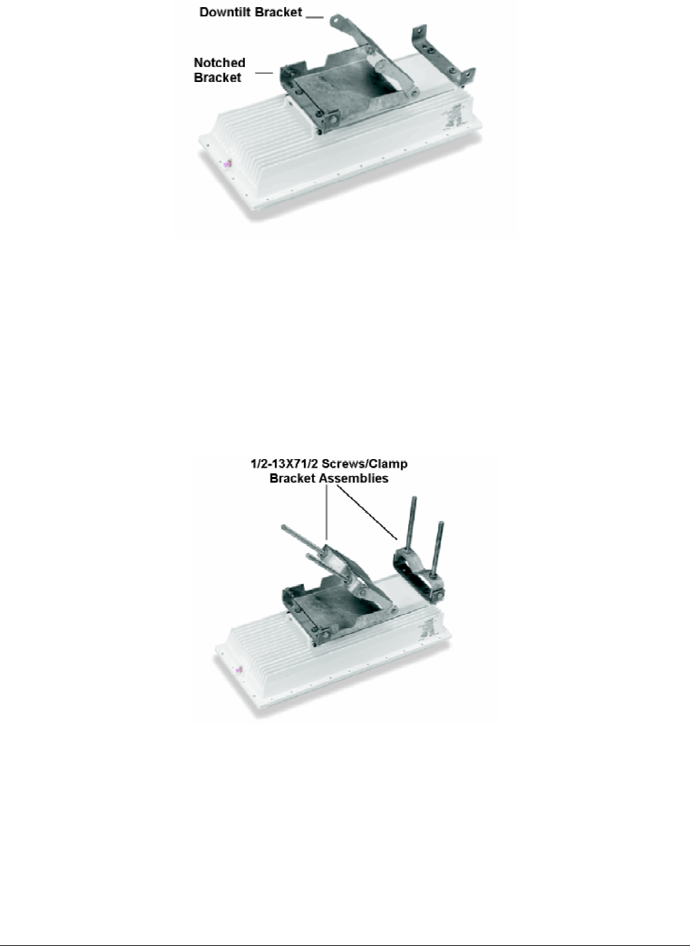
5. Attach the downtilt/notched bracket assembly to the u-shaped mounting bracket near the middle of
the BSU using two sets of 3/8-16x1 1/4 hex head screws, #3/8 split lock washers, and 3/8-16 nuts.
Note: This mounting method lets you point the BSU down when mounted on a pole; to point the BSU up, attach
the downtilt/notched bracket assembly to the u-shaped mounting bracket near the bottom of the BSU.
Chapter 2. Pre-Installation Tasks 19
CPN 63179 Issue Date: 01/24/03
Tsunami Multipoint Version 1.3 Installation Guide
Figure 11. Bracket Assembly Attached to Mounting Bracket
6. Attach one of the 1/2-13x7 1/2 screws/clamp bracket assemblies to the u-shaped mounting bracket
near the end of the BSU using two sets of 3/8-16x1 1/4 hex head screws, #3/8 split lock washers,
and 3/8-16 hex nuts (see Figure 12). (In this configuration, the BSU points down when mounted on a
pole.)
7. Attach the other 1/2-13x7 1/2 screws/clamp bracket assembly to the downtilt bracket using two sets
of 3/8-16x1 1/4 hex head screws, #3/8 split lock washers, and 3/8-16 hex nuts (see Figure 12).
Figure 12. Screws/Clamp Bracket Assemblies Attached
Chapter 2. Pre-Installation Tasks 20
CPN 63179 Issue Date: 01/24/03
Tsunami Multipoint Version 1.3 Installation Guide
Mounting the BSU to a Pole
To mount the BSU to a pole using the attached mounting components:
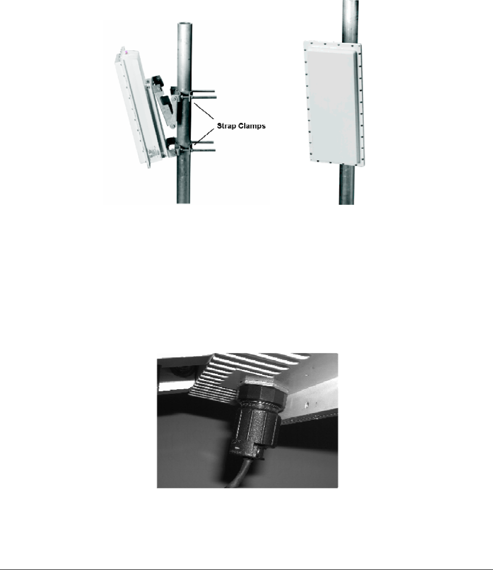
1. Lash the unit to the pole or use a hoisting rope to keep the unit in place while you mount it. Slide the
two strap clamps over the two sets of 1/2-13x7 1/2 screws and secure the strap clamps using four
#1/2 split lock washers and four 1/2-13 hex nuts (see the following photo).
Figure 13. Strap Clamps Attached and Mounted BSU
2. To adjust the up/down tilt (-10 to +5 degrees), move the top or bottom of the BSU (depending on
how you installed the downtilt/notched bracket assemblies) until the unit is roughly positioned at the
correct angle.
3. Connect the supplied Cat 5 cable to the BSU’s Power and Ethernet port as described in the following
notes. Then screw on the outer ring to secure the cable in place.
Figure 14. BSU’s Power and Ethernet Connector
Chapter 2. Pre-Installation Tasks 21
CPN 63179 Issue Date: 01/24/03
Tsunami Multipoint Version 1.3 Installation Guide
The Base Station Unit (BSU) is shipped with a dust cover over the large 18-pin connector. Keep
this cover on until ready to mate with cable connector to avoid getting the connector wet.
To ensure proper weatherproofing, follow these procedures to connect the supplied Cat 5 cable
to the BSU’s Power and Ethernet port.
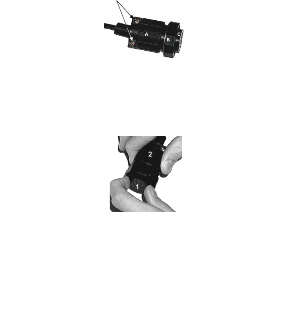
A. Check the BSU connector. The only moving part should be the plastic nut (“B”), which screws
onto the BSU housing.
B. If there is any movement or play between parts A and C, you must tighten these parts before
proceeding; otherwise you could cause connector pins to disconnect or break when you apply
the weatherproofing tape. To tighten, first loosen (but do not remove) the connector’s
screws (indicated with arrows in the previous figure).
C. Then, while holding the pin connection portion (1), turn the bottom portion (2) clockwise until
there is no more movement, making sure you do not over-tighten.
D. Re-tighten the screws.
E. When mating the BSU to the cable connector, first apply a bead of silicone grease or RTV to
the 3mm-wide outward-most flange on the BSU connector (or in the outer ring of the cable-
end mating connector).
F. Then tighten the plastic nut on the cable end to 16 inch-lbs (1.81 N-m). The cable connector
must be tightened onto the BSU sufficiently to compress a small O-ring that resides inside the
male BSU connector. If the O-ring is missing or insufficiently compressed, moisture can get
through into the connector pins.
Chapter 2. Pre-Installation Tasks 22
CPN 63179 Issue Date: 01/24/03
Tsunami Multipoint Version 1.3 Installation Guide
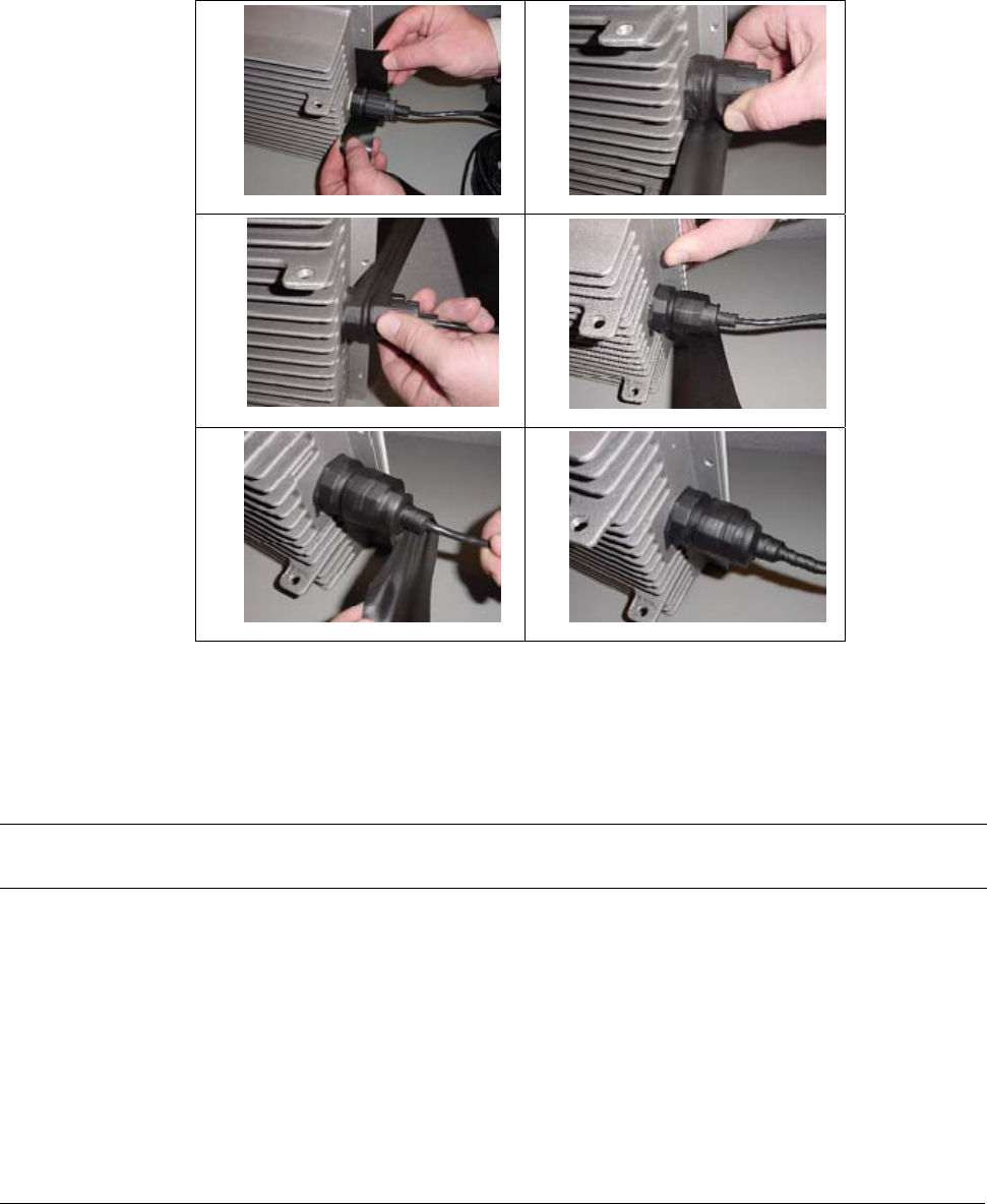
Once mated, over-wrap the connectors (as demonstrated in the following table) with stretchy
black self amalgamating tape (such as CTB-15 CATV TAPE-X5-BK-UN part #22150000 from
DSG – CANUSA 173, Commerce Boulevard, Loveland, Ohio 45140, Tel. 1-800-422-6872) to
ensure a better water seal.
1) 2)
3) 4)
5) 6)
4. Connect the other end of the Cat 5 cable to the BSU’s power supply. (The BSU’s power supply is
ordered and shipped separately. The power supply’s CPN number is 58526.)
5. Plug the power supply into an electrical outlet.
Note: To ensure proper grounding, use the hole on the back of the BSU and the provided grounding screw to attach
a ground wire to the BSU. Use wire grounding techniques in accordance with your local electrical codes.
Chapter 2. Pre-Installation Tasks 23
CPN 63179 Issue Date: 01/24/03
Tsunami Multipoint Version 1.3 Installation Guide
Installing the GPS Antenna
If you do not plan to install multiple BSU in the same geographical area skip this section
If you plan to install multiple BSUs in the same geographical area (for example, one BSU might interfere
with another), you must install the supplied GPS antenna (a small metal plate with a black 2"x 2"
antenna and thin cable) on each BSU. Each BSU uses a global positioning system (GPS) to synchronize
its clock with other BSUs. You also must set each BSU to Multi Sector mode (see “Configuring the
System for Multi-Sector Mode” on page 29).
Mounting the GPS Antenna
To install the GPS antenna:
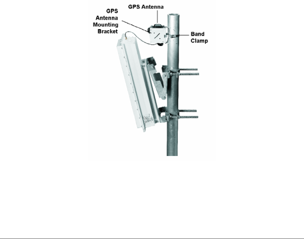
1. Position the GPS antenna in a location where the antenna plate is parallel to the earth/horizon and
the black antenna bump-up can be attached to the BSU (as shown in the following figure). The GPS
antenna should be exposed to as much of the sky as possible so it can acquire at least four GPS
satellites to extract timing signals for the BSU transmission synchronization.
Figure 15. GPS Antenna Mounted on BSU
2. Insert the band clamp through the slots in the GPS antenna-unit mounting bracket and around the
mounting pole. Tighten the clamp around the mounting pole and then tighten the screw in the clamp
to secure the GPS antenna mounting bracket to the mounting pole.
3. Attach the GPS antenna to the GPS antenna mounting bracket using the #10-32x3/8 SEM screws
(the screws with attached washers).
Chapter 2. Pre-Installation Tasks 24
CPN 63179 Issue Date: 01/24/03

Tsunami Multipoint Version 1.3 Installation Guide
4. Remove the water-protection cap from the top of the BSU and screw on the cable from the GPS
antenna to the connector on the top of the BSU.
Installing BSU Configuration Software
The next step is to configure the BSU. The BSU is configured from a PC running the BSU Configuration
Software (Versions 1.4 or 1.5). This PC communicates with the BSU through its Ethernet port. If you
have a PC with the BSU Configuration Software already installed, skip to “Configuring the Base Station”
on page 26; otherwise, install the BSU Configuration software as described in “Appendix B. Installing the
Software and Upgrading Firmware” on page 51.
Operating in a Test Environment
Prior to installation outdoors, you may want to operate the equipment indoors in a test environment to
become familiar with the operating configurations and performance. Furthermore, in situations in which
it is extremely difficult (very low temperature) or costly (on a mountain top) to install or replace the
equipment, you may want to verify operation in an indoor test environment prior to actual installation in
the field. All of the configuration and testing information described in the previous chapters, with the
exception of the actual mounting of the units, apply to an indoor test deployment. The following sections
describe a procedure to set up a pre-installation testing environment for this purpose.
Warnings and Considerations for an Indoor Deployment
Review the following important warnings and considerations before turning on any Tsunami Multipoint
equipment indoors in your test environment.
WARNING! All persons should be at least 5 feet (1.5 meters) away from any antenna when any products
are operational.
Place the antennas at least 30 feet apart, facing each other.
▪ To minimize the multi-path phenomenon, the BSU should be configured to use the lowest transmit
power level (6 dBm) and the most reliable modulation technique (20 Mbps mode). In addition, the
BSU must have GPS and Range Security disabled. Also, make sure the BSU is facing toward the SU.
▪ Do not set up your laptop between the antennas or stand between the antennas.
▪ Try to minimize the movement of objects within the test environment to prevent changes in radio
propagation patterns. Radio signals behave differently indoors than outdoors; using the devices
indoors may have an unintended, negative effect on the performance of the Tsunami Multipoint
system.
▪ For best results, connect at least one computer to the BSU and to each SU.
Chapter 2. Pre-Installation Tasks 25
CPN 63179 Issue Date: 01/24/03

Tsunami Multipoint Version 1.3 Installation Guide
▪ Install the BSU first before installing any SUs.
▪ Once a link has been established, check the RSL at the SU, and if too high, miss-point the antenna
slightly to reduce the receive power.
Configuring the Base Station
Keep in mind the following when configuring a BSU:
▪ The configuration commands are NOT case-sensitive.
▪ Refer to the Operator Commands section of the software’s Help menu (or the Reference manual)
for additional information on command syntax.
▪ The BSU does not provide an on-screen response to many of the available commands.
▪ The BSU saves the configuration settings periodically (approximately every two minutes). Therefore,
after issuing the last configuration change, wait two minutes before recycling power or turning off the
unit to ensure that all of your changes take effect.
To configure the Base Station:
1. On the computer that has the Base Station Configuration Software installed, change the IP address
for its Ethernet card to 192.168.20.xx with a 255.255.255.0 subnet mask (xx can be any number
between 1 and 255 with the exception of 254). The computer and BSU must be members of the same
IP subnet to communicate. When using the Multi-BSU software, the BSU and SU can be on different
subnets (see “Using the Multi-BSU Configuration Software” in the Tsunami Multipoint Version 1.3
Reference Manual for information).
Note: The BSU’s default IP address is 192.168.20.253 with a subnet mask of 255.255.255.0.
2. Run the Base Station Configuration Software on the computer. To do this, from the Windows Start
menu, select Programs Æ Base Station Configuration Software.
Note: The menu bar reads “Base Station Configuration Software” when the computer and BSU are connected to
the same physical network. If the menu bar reads “Configuration Software” only, the two devices are not
on the same physical network; confirm that they are connected to the same Ethernet network, check the
Ethernet cables, and confirm that the BSU is powered on before continuing.
º Type dspconf and press the Enter key to view the BSU’s current configuration settings. If you do
not get a response to this command, confirm that the computer and BSU are on the same IP
subnet.
Chapter 2. Pre-Installation Tasks 26
CPN 63179 Issue Date: 01/24/03

Tsunami Multipoint Version 1.3 Installation Guide
3. Configure the BSU’s IP settings:
Type setIP <IP address> and press Enter, where <IP address> is the new IP address you want to
assign to the unit. For example, type setIP 192.168.20.20 to assign this IP address to the BSU.
A. Close the Base Station Configuration Software and change the IP address of the computer’s
Ethernet card so that it is in the same IP network as the BSU’s new IP address; restart the
computer if necessary.
B. Open the Base Station Configuration Software and use the dspconf command to verify that the
BSU and computer can communicate.
C. Enter setSubnet <subnet mask> where <subnet mask> designates a subnet mask. Proxim
does not recommend using a subnet mask wider than 255.255.248.0.
D. If desired enter gateway <gateway address> where <gateway address> designates the IP
address of the network’s gateway.
4. To set the BSU’s Terminal ID, enter setID <Terminal ID> where <Terminal ID> is a number
between 1 and 2048). For example, setID 1 sets the unit’s Terminal ID to 1.
Note: Each BSU and Subscriber Unit (SU) in a cell must have a unique Terminal ID.
5. Use the setFrameSync command to set the proper GPS operating mode.
º When performing indoor tests, Frame Sync must be set to Independent mode (setFrameSync
1). A BSU’s transmitter does not turn on if Frame Sync is set to Multi Sector while indoors.
Frame Sync should be set to one of the Multi Sector modes only when multiple BSUs are installed
in the field; these modes enable a BSU’s GPS receiver so it can synchronize its frame timing with
other BSUs. See “Configuring the System for Multi-Sector Mode” on page 29 for details about
configuring and testing multi-sector operation.
6. If Range Security is enabled (set to 1), enter rangeSecurity 0 (zero) to disable this feature. You can
enable it later once the SUs have been installed in the field.
7. Set the desired data rate using the modulation command (modulation <0 (60Mbps) | 1 (40 Mbps) |
2 (30 Mbps) | 3 (20 Mbps)>). This step is not applicable for BSUs that support 20 Mbps operation
only.
º Set the desired frequency plan using the freqPlan command. (freqPlan < 4 (four channel | 5
(channel) | 6 (channel)>). Tsunami Multipoint offers several frequency plans and operating
frequencies to provide a means for overcoming interference. If one part of the 5.8 GHz spectrum
is occupied when you deploy the product, you can select a different frequency plan to bypass the
interfering frequency.
Chapter 2. Pre-Installation Tasks 27
CPN 63179 Issue Date: 01/24/03

Tsunami Multipoint Version 1.3 Installation Guide
8. Set the desired frequency plan using the frequency command. (frequency < a | b | c | d | e| f >;
with e being available for the 5 and 6 channel plans and f being available for the 6 channel plans
only.
9. Set the BSU’s desired transmit power level using the txPowerLevel command.
Note: Typically the power level is set to 17 dBm in the field (maximum setting) and 6 dBm for indoor range
testing (minimum level).
10. Set the desired transmit power auto-enable mode with the txPowerAutoEnable command
(txPowerAutoEnable < 0 (off) | 1 (on)>. When auto-enable is set to on the BSU will automatically
start transmitting after any power cycle.
11. Set the desired routing mode with the routingMode command. (routingMode < 0 (IP routing | 1
(Bridging)>).
Note: After you issue the routingMode command, you may need to clear the PC’s arp table. (restarting the PC
used to configure the BSU will do this).
12. Turn on the BSU using the txPower command (txPower <0 (off) | 1 (on)>).
At this point the BSU is configured and ready to operate. Also, see “Advanced Configuration Options” and
“Command Reference” in the Tsunami Multipoint Version 1.3 Reference Manual for information about the
other commands used to configure the BSU (such as setting proxy, RIP, static IPs, and so on).
Adding Subscribers to the BSU Database
Subscriber units will not be able to enter the network until they are added to the BSU database.
1. Identify the Subscriber Units (SUs) you intend to use with this BSU and write down each device’s
MAC address (which is printed on the product label).
2. Add the first SU to the BSU’s database by entering addSU <MAC address> <Terminal ID>.
º When typing the MAC address, separate each pair of digits with a colon or a blank space.
º The Terminal IDs range from 1 to 1023; assign a unique ID to each BSU and SU in a cell.
For example, if the SU’s MAC address is 00-04-44-12-34-56 and you want to assign Terminal ID
2 to this SU, enter addSU 00:04:44:12:34:56 2.
Note: Add an SU to the BSU’s database before installing or turning on the SU.
Chapter 2. Pre-Installation Tasks 28
CPN 63179 Issue Date: 01/24/03

Tsunami Multipoint Version 1.3 Installation Guide
3. Configure the SU’s IP settings:
º Enter setSUIP <Terminal ID> <IP address> to set the SU’s IP address. Proxim suggests that
you configure each SU with a unique IP address in the same IP subnet as the BSU in Bridging
mode and configure each SU with a specific subnet in IP routing mode.
º Enter setSUSubnet <Terminal ID> <subnet mask> to set the SU’s subnet mask.
4. Repeat Steps 2 and 3 for each SU that you want to add to the Tsunami Multipoint system.
5. Enter dspSU to view the list of SUs that have been added to the BSU’s database.
6. Install the SUs as described in “Chapter 3. Deploying the Subscriber Unit” on page 31.
Configuring the System for Multi Sector Mode
If you are installing the BSU in the same geographical location as other BSUs, i.e., in a location where
one BSU may interfere with another, set the unit to Multi Sector mode; this enables the GPS receiver.
GPS is used to ensure that all BSUs in the same geographical region transmit and receive at the same
time. In additional, the ratio of downlink to uplink slots must be the same for all BSU’s that may
interfere with each other. Together, these eliminate the possibility of a BSU transmitting while a co-
located BSU is receiving. This synchronization is achieved using the timing signal supplied by the GPS
receiver. The GPS receiver needs to see four satellites to obtain an accurate time. Once time has been
initialized, the receiver can keep accurate time even if it sees only a single satellite.
There are two multi-sectors modes; auto-restart and auto-resync. The difference between these modes
has to do with how the BSU synchronizes its timing to gps after an outage. The reader is referred to the
TMP reference manual for more details. To configure the BSU for Multi Sector Mode, use the
setFrameSync command (setFrameSync <0 (Multi-sector with auto-restart | 1 (independent – NOT
multisector) | 2 (multi-sector with auto-resync). Multi-sector mode with auto-resync is the recommended
mod). To turn off Multi Sector Mode, enter setFrameSync 1, indicating Independent (GPS is not used).
Testing the GPS Receiver
The GPS Receiver Test examines the quality of the GPS signal. This test is for use only in the field by
customers who have installed multiple Base Station Units (BSUs) in the same location (with the Frame
Sync parameter set to Multi Sector).
This tool tests the GPS quality for BSUs that receive timing information from GPS satellites.
Note: The BSU must have the GPS antenna connected to receive GPS signals. See “Mounting the GPS Antenna.”
Chapter 2. Pre-Installation Tasks 29
CPN 63179 Issue Date: 01/24/03

Tsunami Multipoint Version 1.3 Installation Guide
Follow these steps to run the test:
1. Open the Base Station Configuration Software.
2. Enter BSUlog 1 1.
3. The second output column is GPS sync, which will read –1 until the GPS can acquire the requisite
number of satellites. When this number reads 0, GPS has acquired at least one satellite; when it
reads 4, at least four satellites have been acquired and GPS is functional.
4. Enter BSUlog 0 to turn off BSU log.
5. Enter pp3d 1 to start the GPS test.
º The Base Station Configuration Software reports the following values (from left to right):
Column 1: Time error in half-chip; this value should be less than 80
Column 2: Frequency error
Column 3: Synchronize filter; this value must equal 20
Column 4: Not applicable
Column 5: GPS message; this value must be 4
Column 6: Visible sat; this value must be 4
Column 7: Time of week in 10 ms
Columns 8 & 9: Not applicable
º Column 1 provides information concerning the level of frame synchronization and Column 6
provide information about the number of visible satellites.
6. Enter pp3d 0 (zero) to end the GPS test.
Chapter 2. Pre-Installation Tasks 30
CPN 63179 Issue Date: 01/24/03
Tsunami Multipoint Version 1.3 Installation Guide
Chapter 3. Deploying the Subscriber Unit
Mounting the Subscriber Unit (SU)
The outdoor component of the Subscriber Unit (SU) is designed to directly mount to a pole. Using the
supplied U-bolts, you can mount the SU to a 1-1/4 inch to 1-3/4 inch pole (outside diameter). Using
optional mounting brackets, you can mount the SU to a wall or other flat surface.
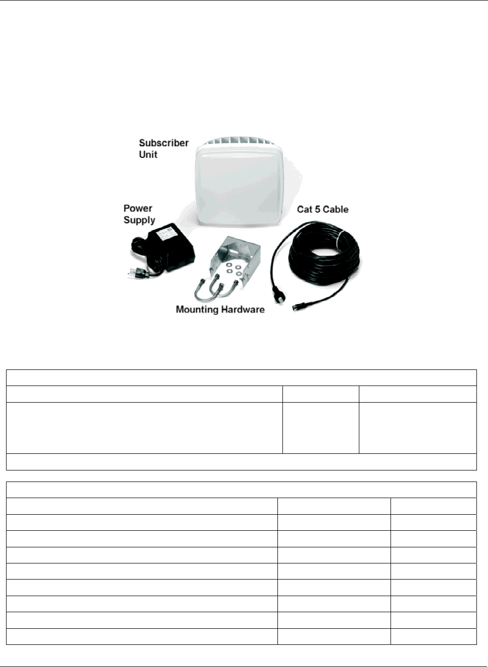
Figure 16. Subscriber Unit Installation Kit
Tsunami Subscriber Unit System
Title Part Number Quantity
SU Installation Kit, consisting of the following:
Power Supply, LINEAR, 24 WATT, 24V @ 1Aa
Cable Assembly, Cat 5, WRR Outdoor, 25M
Mounting hardware (see the following table)
6H0-00716-00
100-00737-01
1 each
1 each
1 set
a 220V, SWITCHING, 28V @ 1A REGULATED power supply and international power cord available.
SU Mounting Hardware
Mounting Hardware Part Number Quantity
Mounting Clamp Housing, WRR 200-00775-00 1 each
U-Bolt 1 ½” SCH 40 PIPE 5/16-18 720-01132-02 2 each
Nut, KEP, @5/16, with Lock Washer, CRES 740-00451-00 4 each
Washer, Flat, 5/16, CRES 730-00450-00 4 each
Screw, Machine, SEM, @10-32 x .5, Ext Star, CRES 720-00937-00 2 each
Nut, KEP, #10-32, CRES 740-00938-00 2 each
Screw, #10-16x3/8 Type B, Pan Head Phillips, SS18-8 720-01133-00 1 each
O-Ring, 1.00” Idx1.14” OD 720-00769-00 1 each
Chapter 3. Deploying the Subscriber Unit 31
CPN 63179 Issue Date: 01/24/03
Tsunami Multipoint Version 1.3 Installation Guide
Note: The following instructions assume that you will slide the SU’s mounting bracket/pole assembly onto a pole. If
this is not practical (for example, the pole is too tall or its top and bottom are permanently mounted to struc-
tures), follow the steps below, but assemble the mounting bracket/pole assembly around the pole.
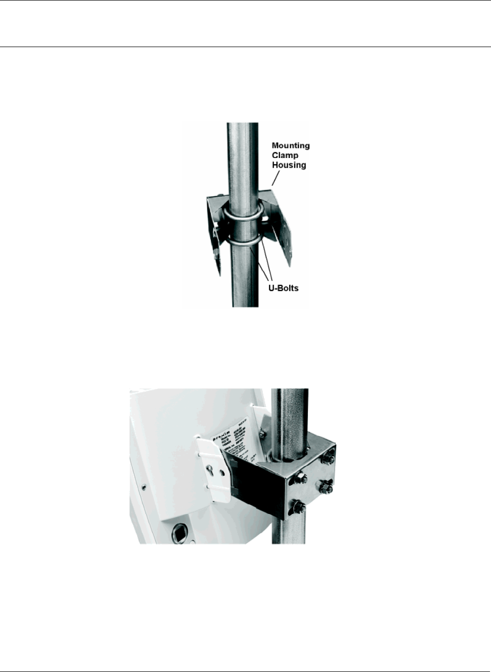
1. Insert the two U-bolts into the mounting clamp housing and attach the two #5/16 nuts and 5/16 flat
washers.
2. Slide the mounting clamp housing/pole clamp assembly down the pole.
Figure 17. Mounting Clamp Housing and U-Bolts Attached
3. Squeeze the sides of the mounting clamp housing and slide it inside the flange protruding from the
back of the SU until the pins extend into the holes on the side of the flange.
Figure 18. Mounting Bracket Attached to SU
Chapter 3. Deploying the Subscriber Unit (SU) 32
CPN 63179 Issue Date: 01/24/03
Tsunami Multipoint Version 1.3 Installation Guide
4. Insert the two #10-32 screws in the sides of the mounting clamp housing/pole clamp assembly and
loosely attach the two #10-32 nuts.
Figure 19. Mounted SU
5. After you aim the SU (see “Aiming the SU” on page 35), tighten the two #10-32 screws and nuts to
secure the SU in position.
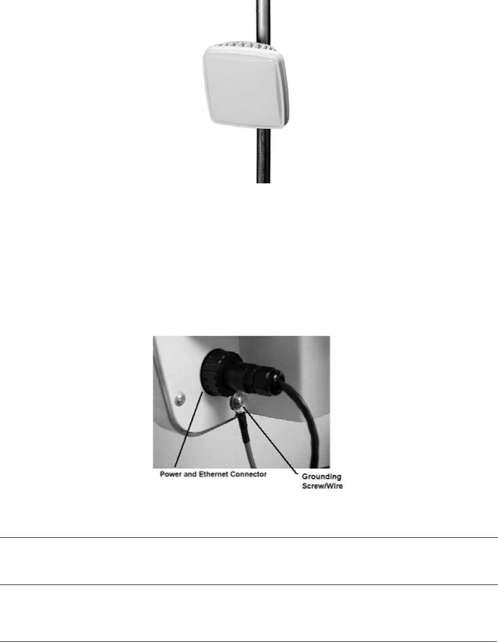
6. Insert the O-ring into the SU’s Power and Ethernet port.
7. Connect one end of the supplied Cat 5 cable to the SU’s Power & Ethernet port and screw on the
outer ring to secure the cable in place.
Figure 20. SU’s Power and Ethernet Connector and Grounding Screw
Note: To ensure proper grounding, use the hole on the back of each SU and the provided grounding screws to
attach a ground wire to each radio. Use wire grounding techniques in accordance with your local electrical
codes.
Chapter 3. Deploying the Subscriber Unit (SU) 33
CPN 63179 Issue Date: 01/24/03

Tsunami Multipoint Version 1.3 Installation Guide
8. Connect the other end of the Cat 5 cable to the SU’s power supply. Be sure the Tsunami Multipoint
Subscriber Unit connector is properly “contacted” or the unit may fail; you should hear a “click” when
installing the cable connector to its chassis. The proper way to install is as follows:
A) Insert the O-ring into the SU’s Power and Ethernet port.
B) Loosen the rear nut on the end of connector cable.
C) Pull the RJ-45 head out a few millimeters from the connector body.
D) Push the RJ-45 head into the chassis connector and listen for a solid “click.”
E) Push the water seal cap back and tighten the cap.
F) Tighten the rear nut.
Note: While not necessary, it is advisable to implement additional external weatherproofing, such as
weatherproof tape and silicon at the inside base of the threaded part of the connector.
9. Connect one end of a Cat 5 cable to the SU’s power supply’s RJ-45 port and the other end to a switch
or directly to the computer onto which you installed the Subscriber Utility.
10. Plug the SU’s power supply into an electrical outlet.
Installing the Subscriber Utility Software
The subscriber utility is used in the antenna pointing process and must be installed to finish the SU
installation.
1. Identify the computer on which you plan to run the Subscriber Utility.
Note: See “System Requirements for Base Station Configuration Software” on page 51 for operating system
and hardware requirements.
2. Insert the Tsunami MP CD (provided with the product) into the computer’s CD-ROM drive and open
the CD’s config software folder.
Note: If the computer has Microsoft IIS (Internet Information Services) running, disable or uninstall it before
running the Subscriber Utility.
3. Double-click SUSETUP.HTM or use a Web browser to open the file.
4. Place a checkmark next to the Include VM in download option to install Java Virtual Machine (VM).
Note: You need not add VM if your computer already has a version of VM installed.
5. Click the Start Installer for Windows button to begin the software installation.
Chapter 3. Deploying the Subscriber Unit (SU) 34
CPN 63179 Issue Date: 01/24/03
Tsunami Multipoint Version 1.3 Installation Guide
6. Follow the on-screen instructions to install the software.
7. Click Done when the installation is finished to close the installer.
Aiming the SU
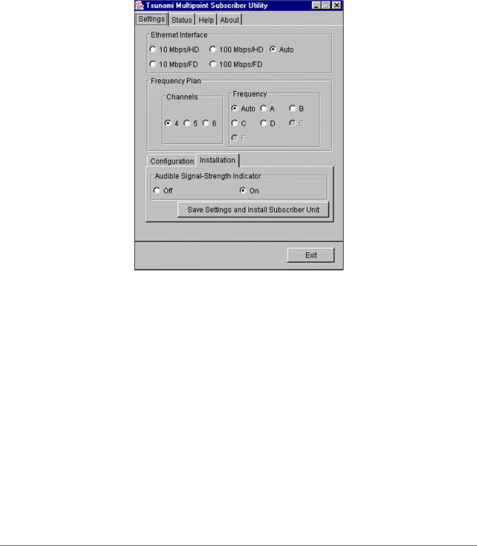
1. Launch the Subscriber Utility.
Figure 21. Settings Page in Subscriber Utility
2. Choose the desired frequency plan and operating frequency. The factory default is the 4 channel
frequency plan and frequency auto (the SU looks through all frequencies). Selecting a specific
frequency forces the SU to search for a BSU on that specific frequency only. When the Auto option is
selected, the SU searches all frequency channels for a given plan until it finds the strongest signal.
3. Turn on the Audible Signal-Strength Indicator (if not already set to On).
Chapter 3. Deploying the Subscriber Unit (SU) 35
CPN 63179 Issue Date: 01/24/03

Tsunami Multipoint Version 1.3 Installation Guide
4. Click Save Settings and Install Subscriber Unit to launch the aiming tool.
Figure 22. Aiming Tool in Subscriber Utility
5. Slowly adjust the position of the SU until you have maximized the strength of the radio signal.
º The SU beeps after it has detected a signal from the BSU. The beeps increase in frequency as the
strength of the signal received from the BSU increases.
º The Receive Signal Quality indicator within the Subscriber Utility’s Installation window reports the
strength of the radio signal.
6. Click OK to close the aiming tool.
7. If you have left the Base Station Configuration Software running on the computer connected to the
BSU, a notification is displayed once the SU has successfully joined the network (this is known as a
“net entry” notification).
Displaying Link Status Information
The Status window displays the current information at the SU, as well as information about the link
between the BSU and the local SU. The information is described following the figure. To display the
Status window, launch the Subscriber Utility and then select the Status tab.
The Status window is displayed, as shown in the following figure.
Chapter 3. Deploying the Subscriber Unit (SU) 36
CPN 63179 Issue Date: 01/24/03
Tsunami Multipoint Version 1.3 Installation Guide
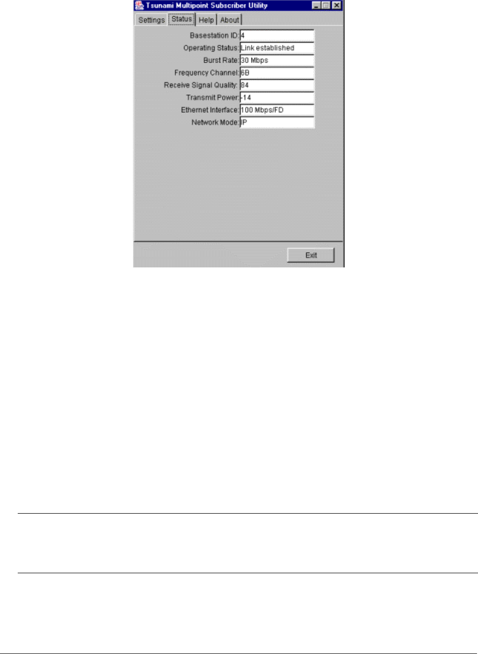
Figure 23. Subscriber Utility Status Window
Base Station ID
Displays the Terminal ID assigned to the BSU with which the SU communicates.
Operating Status
When the link status between the BSU and local SU changes (for example, when you first power up
the units, change their configuration, and so on) the following status messages appear in this field:
Searching for Outbound
SU searches for an outbound signal (that is, a signal transmitted from the BSU)
Inbound fine sync
Indicates outbound signal detected and the SU is attempting to synchronize with the inbound signal
Link established
Indicates the link is established between the BSU and local SU.
Note: The No connection message indicates that the software is unable to establish a link between the BSU
and local SU. Also, the ODU Not Connected message indicates that the PC used to configure the SU is
not communicating with it. See “Troubleshooting” in the Tsunami Multipoint Version 1.3 Reference
Manual for possible causes and solutions to these problems.
Burst Rate
Shows the current Modulation setting. See “Specify the Desired Modulation (Data Rate)” on page 49
for information.
Chapter 3. Deploying the Subscriber Unit (SU) 37
CPN 63179 Issue Date: 01/24/03