Proxim Wireless S58-B60C Unlicensed Spread Spectrum Transceiver User Manual Backing down from TNG CCI 2
Proxim Wireless Corporation Unlicensed Spread Spectrum Transceiver Backing down from TNG CCI 2
Contents
- 1. Antenna Installation Manual
- 2. Installation Manual 1
- 3. Installation Manual 2
- 4. Installation Manual 3
Installation Manual 3

Tsunami Multipoint Version 1.3 Installation Guide
Frequency Channel
Shows the current channel plan/frequency setting (for example, 4C). See “Change the Frequency
Plan and Operating Frequency” on page 50 for information. By default, the SU is set to automatically
search for the correct frequency channel.
Receive Signal Quality (dBm)
Shows the quality of signal received by the local SU (in dBm). This value represents the estimated
received signal level, plus an offset of 120 dB. A received signal quality level over 40 (which
represents a signal level of -80 dBm) shows an acceptable signal quality.
º You can use this field to fine tune BSU/SU alignment. After you mount the units outdoors, check
the Receive Signal Quality value as you make fine adjustments to the BSU/SU alignment until you
obtain optimal signal quality.
Transmitter Power
Shows the SU’s current transmitter power (-30 to +36).
Ethernet Interface
Shows the current Ethernet interface setting. If the Ethernet interface was set to auto-netotiate, this
entry contains the results of the auto-negotiation.
Network Mode
Shows the current network mode: Bridging, VPN, or IP Routing.
Confirming Network Activity
Attempt to ping from a computer connected to:
▪ An SU to the BS (BSU and SU must have different IP addresses to do this. If the BSU and SU are
configured with the same IP address, the local unit responds to the ping (that is, if the BSU and SU
have the same IP address and you ping the BSU from a host connected to the SU, the SU responds to
the ping).
▪ The BSU to the SU. (BSU and SU must have different IP addresses to do this. If the BSU and SU are
configured with the same IP address, the local unit responds to the ping (that is, if the BSU and SU
have the same IP address and you ping the BSU from a host connected to the SU, the SU responds to
the ping).
If successful and possible, attempt to ping from a computer on the SU side of the network to a computer
on the BSU side of the network.
Chapter 3. Deploying the Subscriber Unit (SU) 38
CPN 63179 Issue Date: 01/24/03

Tsunami Multipoint Version 1.3 Installation Guide
If the ping tests are unsuccessful, attempt the following:
▪ Check all IP and computer configurations (for example, if you attempt to ping the BSU from the SU
configuration computer and the BSU and SU’s are in separate networks you must have the
configurations computers gateway set to the SU for the ping to work.)
▪ Adjust the network’s IP settings, if necessary, to achieve IP connectivity.
If the above fails refer to “System Diagnostics” to help debug possible link problems.
Note: See “Chapter 4. System Diagnostics and Operating Tips” on page 40 for information about running system
diagnostics to make sure the equipment is operating as expected .
Chapter 3. Deploying the Subscriber Unit (SU) 39
CPN 63179 Issue Date: 01/24/03
Tsunami Multipoint Version 1.3 Installation Guide
Chapter 4. System Diagnostics and Operating Tips
This section describes several diagnostic tests you can perform once the Tsunami MP equipment is
installed. These tests assist you in determining whether the equipment is functioning as expected. In
addition, we include some miscellaneous useful information for deploying a Multipoint network.
Radio Diagnostics
Use the diagnostic tools described in this section to determine if your wireless link is stable. You can also
use these tools to help fine-tune antenna positions to establish a good link.
BSU and SU Logs
You can display BSU and SU logs to help troubleshoot possible link reliability and interference issues.
These tools have no impact on data traffic, and can be used in conjunction with configuration parameters
(such as IPC settings, modulation modes, and operating frequencies) and possible antenna relocation to
obtain the best possible path. The goal is to maximize the Es/N0 ratio.
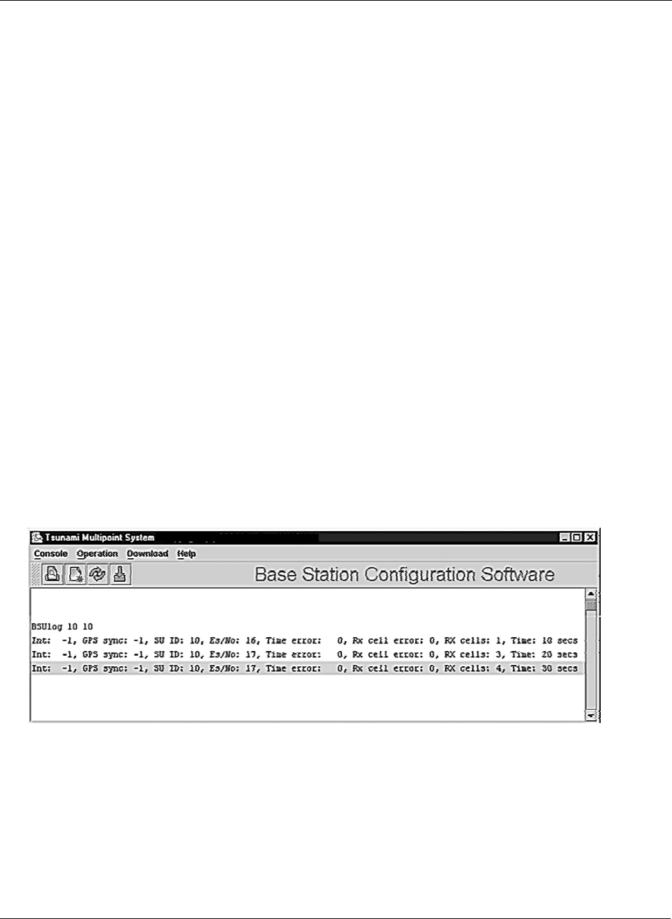
Displaying the BSU Log
Follow these steps to enable the BSU log:
1. Enter BSUlog (Terminal ID> <time> where <Terminal ID> is the Terminal ID of the SU to be
monitored and <time> specifies the polling period (in seconds).
Figure 24. BSU Log in the Base Station Configuration Software
2. When finished, disable the BSU log by entering BSUlog 0 (zero).
Chapter 4. System Diagnostics and Operating Tips 40
CPN 63179 Issue Date: 01/24/03

Tsunami Multipoint Version 1.3 Installation Guide
Monitor the Es/No ratio (Es/No reports the energy per symbol-to-noise spectral density ratio (in dB)).
Low Es/N0 or varying Es/N0 can indicate path or interference problems. The Es/No requirement varies
based on the modulation mode:
20 Mbps: Es/No > 4 + IPC value
30 Mbps: Es/No > 5 + IPC value
40 Mbps: Es/No > 9 + IPC value
60 Mbps: Es/No > 12 + IPC value
In addition, the BSU log provides the following information:
Int
Relative interference of the power received at the BSU (a value of 0 (zero) nominally shows no
interference)
GPS sync
-1 indicates GPS sync is disabled; 4 indicates GPS sync is enabled. GPS synchronization is used when
the system is in Multi Sector mode (multiple BSUs installed in the same location; see “Configuring the
System for Multi-Sector Mode” on page 29 for more information).
SU ID
The Terminal ID of the monitored SU
Time error
Shows the uplink (or inbound) ranging error
Rx cell error
Shows the number of lost uplink cells
Rx cells
Shows the total number of uplink cells
Time
Shows the cumulative polling time (in seconds)
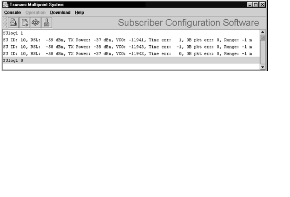
Displaying the SU Logs
You can display two different types of SU logs: SUlog1 and SUlog2. To display the SU logs, install the
Base Station Configuration Software on the PC used to configure the SU (see “Installing the Base Station
Configuration Software” for information) and then execute the commands described below.
Follow these steps to enable an SU log:
1. Enter SUlog1 <time> or SUlog2 <time> where <time> specifies the polling period (in seconds).
(Specify SUlog1 to display SUlog1; specify SUlog2 to display SUlog2. See the information below for
details about these two logs.)
Chapter 4. System Diagnostics and Operating Tips 41
CPN 63179 Issue Date: 01/24/03
Tsunami Multipoint Version 1.3 Installation Guide
2. When finished, disable the SU log by entering SUlog1 0 (zero) or SUlog2 0 (zero) (depending upon
which log you displayed).
SUlog1 provides the following information:
SU ID
The Terminal ID of the monitored SU.
RSL
Shows the shows the RSL (receiver signal level) at the output of the antenna (in dBm).
TX Power
Shows the SU’s TX power at the input to the antenna (in dBm).
VCO
Shows the relative frequency offset of the VCO (voltage control oscillator) (in Hz).
Time error
Shows the synchronization error (in 1/512 symbol), generally magnitude (should be less than 8).
OB pkt error
Shows the number of out-of-sequence outbound packets.
Range
Shows the SU’s distance from the BSU (in meters).
Figure 25. Log 1
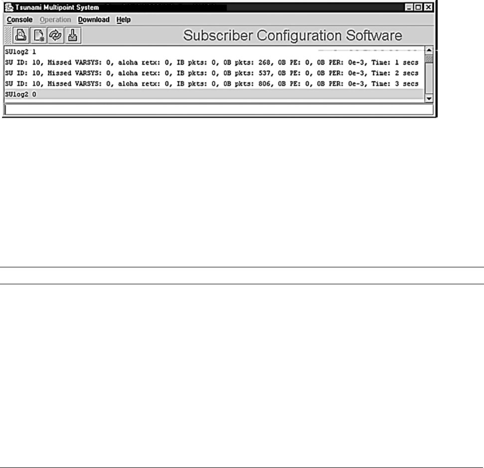
SUlog2 provides the following information:
SU ID
The Terminal ID of the monitored SU.
Missed VARSYS
Shows the number of missing downlink control packets.
aloha retx
Shows the number of packets retransmitted due to collisions (collisions are a normal event on
contingent channels. An excessive number may indicate a problem).
Chapter 4. System Diagnostics and Operating Tips 42
CPN 63179 Issue Date: 01/24/03
Tsunami Multipoint Version 1.3 Installation Guide
IB pkts
Shows the number of inbound packets transmitted.
OB pkts
Shows the number of outbound packets received.
OB PE
Shows the number of outbound packet errors.
OB PER
Shows the error rate for outbound packets received.
Time
Shows the cumulative polling time (in seconds).
Figure 26. SU Log 2
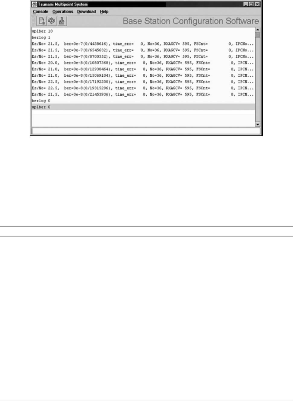
Uplink BER Test
The Uplink BER Test determines the BER (bit error rate) of the uplink signal. This is an out-of-service
diagnostic tool and the data connection is terminated for the length of the test. Use this tool to determine
whether the link is stable (that is, there are no bit errors). You can also monitor these test results to fine
tune antenna alignment to get the strongest link possible.
Note: Do not run this test if users are sending data across the radio link.
Follow these steps to run the Uplink BER Test:
1. Open the Base Station Configuration Software.
2. Enter uplber <Terminal ID> to start the test for a particular SU. <Terminal ID> is the Terminal
ID of the SU of interest.
3. Enter berlog 1 to view the test results.
Chapter 4. System Diagnostics and Operating Tips 43
CPN 63179 Issue Date: 01/24/03
Tsunami Multipoint Version 1.3 Installation Guide
Figure 27. BER Log in Base Station Configuration Software
4. Monitor the BER test results. The Es/No is reported in column 1 and BER is reported in column 2. The
BER should initially read 0E-6 or oE-7 but then change to 0E-8 and finally to 0E-9 while the test is
running. This corresponds to 0 (zero) bit errors. The numbers in parentheses indicates the number of
errors over the total. 1E-6 indicates a bit error rate of 1 bit error received for every million bits sent.
5. When finished, disable the Uplink BER Test by first entering berlog 0 (zero) and then entering
uplber 0 (zero).
Note: The data connection does not resume until the uplber 0 (zero) command has been issued.
Network Configuration Tips
Keep the following points in mind when configuring your PMP network.
Tips for Testing PMP Network Under IP Routing Mode
Make sure to configure the BSU such that:
▪ If the BSU is connected to a router, make sure the router port to which the BSU is connected is
defined as the BSU’s default gateway. Also, make sure the BSU is specified as the router port’s
default gateway.
▪ The IP addresses of the BSU and the router port reside in the same subnet (this is required).
Chapter 4. System Diagnostics and Operating Tips 44
CPN 63179 Issue Date: 01/24/03

Tsunami Multipoint Version 1.3 Installation Guide
Make sure that an SU and its directly connected devices are in the same subnet. The subnet address of a
device can be obtained by performing a logical “AND” of the device’s IP address with its subnet mask. A
subnet mask of 255.255.255.0 implies that there are 255 IP addresses within the same subnet.
If the IP address of a PC connected to a SU is not dynamically assigned:
▪ Make sure the PC’s IP address appears in the SU’s static IP list (see “addSUIP Command” in the
Tsunami Multipoint Version 1.3 Reference Manual). Otherwise, if the SU is running in Restricted
mode, the PC cannot access the wireless network.
▪ Configure the PC to point to the SU as its default gateway.
In the latest firmware release, the proxy setting is turned on automatically; do not change this setting.
Tips for Testing VLAN Switching
Before changing the BSU Configuration to VLAN switching, make sure that the BSU and the BSU console
are connected to a VLAN switch. Otherwise, if you turn on VLAN tagging, you cannot talk to the BSU
because the PC hosting the BSU Console cannot send or receive VLAN frames.
Tips for Anyone Operating the PMP Network
When changing back and forth between Bridging mode and IP Routing mode (see “routingMode
Command” in the Tsunami Multipoint Version 1.3 Reference Manual), always remember to manually
clear the ARP table of your PC.
Do not turn off the power of the Base Station Unit “at-will,” because the Base Station Unit might be
saving internal variables or configuration parameters to the flash memory at that moment. Always wait
for a minute after entering an operator command before shutting down the BSU.
Always follow the simple proxy rule and fundamental principles concerning subnets and default gateways
in planning and analyzing the PMP network. A good understanding of basic IP networking is required,
regardless of whether you operate the PMP network in IP Routing or Bridging mode.
If you cannot get the network to work, there is most likely a setup error. Check the network configuration
using the tips above and try again.
Protecting the System
Tsunami Multipoint provides ways to prevent unauthorized users from communicating with the BSU and
SUs. You can password-protect the system to prevent unauthorized access and use the Range Security
option to prevent unauthorized SUs from communicating with a BSU.
Chapter 4. System Diagnostics and Operating Tips 45
CPN 63179 Issue Date: 01/24/03

Tsunami Multipoint Version 1.3 Installation Guide
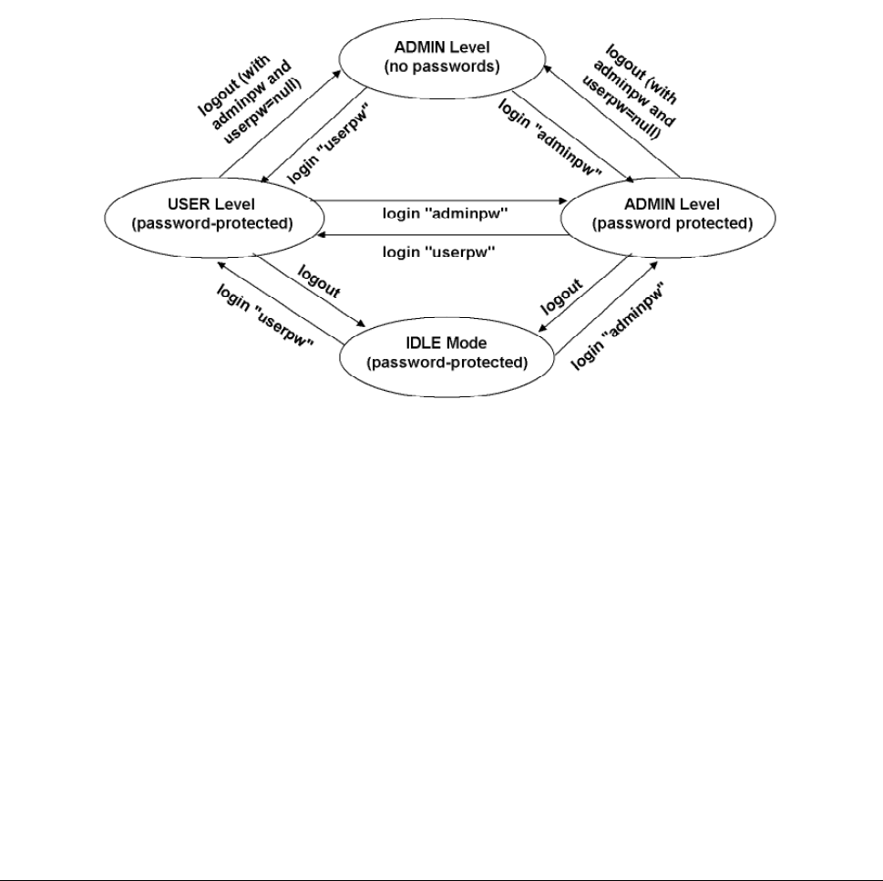
Password Protection
Tsunami Multipoint provides two levels of password protection:
▪ user level – lets the user display the system’s current status only.
▪ admin level – lets the user display the system’s status and change its configuration.
The default password is “null.” Password protection for either password level (user or admin) can be
turned on and off. By default, password protection is turned off.
Passwords can be from 1 to 16 characters; any combination of alphanumeric characters is allowed,
except for these special characters: " , . ’ ‘ ^ { } | \ / ; : ] [ ( )
If you forget your password, contact Proxim’s Customer Service department to obtain a new one. See
“Appendix F. Technical Support and Training” on page 76 for Proxim’s contact information.
Specifying a User-Level Password
To define the user-level password, from the BSU console enter:
setpw user<oldpw><newpw><newpw>
where:
<oldpw> = the old password (the default password is “null”)
<newpw> = the new password
After defining the new user-level password, enter logout. Log in with the new password (see Logging In
on page 47 for information).
Specifying an Admin-Level Password
To define the admin-level password, from the BSU console, enter:
setpw admin<oldpw><newpw><newpw>
where:
<oldpw> = the old password (the default password is “null”)
<newpw> = the new password
After defining the new admin-level password, enter logout. Log in with the new password.
Note: If you specify either level of password without specifying a password for the other level, when you log out or
restart the BSU, the system comes up in password-protected mode. Log in and enter the password you
specified. For example, if you specify “admin” for the admin-level password and then log out or restart the
BSU, enter login admin to access the system. This allows access to the admin-level.
Chapter 4. System Diagnostics and Operating Tips 46
CPN 63179 Issue Date: 01/24/03
Tsunami Multipoint Version 1.3 Installation Guide
Turning Off Password Protection
To turn off password protection, from the BSU console, enter setpw<level><oldpw><null><null>
where:
<level> = either admin or user, depending upon which level of password protection you want to
remove. For example, if the current admin password is “superuser,” to remove the admin
password, enter setpw admin superuser null null.
<oldpw> = the old password.
If you turn off both display-level and user-level password protection, restart the BSU to refresh its
memory.
Figure 28. Password Definition/Usage Diagram
Logging In
If password protection is turned on, you must “log in” to the system to either display system status
(user-level privileges) or change the system’s configuration (admin-level privileges).
To log in, enter login <password> where <password> is either the user-level or admin-level password.
Chapter 4. System Diagnostics and Operating Tips 47
CPN 63179 Issue Date: 01/24/03

Tsunami Multipoint Version 1.3 Installation Guide
Activating Range Security
The Range Security option helps prevent unauthorized SUs from communicating with a BSU. When the
Range Security option is on, if an SU attempts to enter the network, the BSU checks the range value
reported by the SU. This works as follows:
▪ The first time the SU tries to enter the network, the SU’s range is stored in the BSU’s flash memory
for future reference.
▪ Then, if the SU enters the network again (when Range Security is on) and its reported range does not
match the range that was previously stored in the BSU’s flash memory, the SU is denied network
entry and an alarm is sent to the BSU console.
To activate the Range Security option, from the BSU console, enter rangeSecurity 1.
Chapter 4. System Diagnostics and Operating Tips 48
CPN 63179 Issue Date: 01/24/03

Tsunami Multipoint Version 1.3 Installation Guide
Appendix A. Initial Settings
Specify the Desired Modulation (Data Rate)
To configure the BSU to use the modulation setting required by your application (20, 30, 40, or 60 Mbps),
from the BSU console, enter modulation <mode number>, where:
<mode number> =
0 (zero) = QAM16 (60 Mbps)
1 = QAM8 (40 Mbps)
2 = QPSK3Q (30 Mbps)
3 = QPSK1H (20 Mbps)
The BSU automatically restarts and then comes up with the new modulation setting. The Subscriber Units
adopt the new modulation setting (the new modulation setting appears in the Burst Rate field on the
Status page of the Subscriber Utility).
Note: This step is not applicable if the BSU operates at 20 Mbps only.
Specify the BSU’s Gateway Address
In general, you should specify the IP address of the router connected to the BSU as its gateway address.
If your network does not have a router installed, specify the IP address of the BSU console. To specify the
BSU’s gateway address, from the BSU console, enter gateway <gateway address> where <gateway
address> is the IP address of the router attached to the BSU or the BSU console.
Select the Routing Mode
Set the BSU to operate in IP Routing mode or Bridging mode. A BSU is set to IP Routing mode by
default. See the “routingMode” command in the Tsunami Multipoint Version 1.3 Reference Manual for
more information about these modes. After you change the routing mode, the BSU restarts and forces all
the SUs in its sector to restart. The BSU and SUs then come up with the new routing mode.
To select Bridging as the routing mode, from the BSU console, enter routingMode 1.
To select IP Routing as the routing mode, enter routingMode 0 (zero).
Appendix A. Initial Configuration Settings 49
CPN 63179 Issue Date: 01/24/03

Tsunami Multipoint Version 1.3 Installation Guide
Change the Frequency Plan and Operating Frequency
Tsunami Multipoint offers several frequency plans and operating frequencies to provide a means for
overcoming interference. If one part of the 5.8 GHz spectrum is occupied when you deploy the product,
you can select a different frequency plan to bypass the interfering frequency.
To select a frequency plan and operating frequency, specify a frequency plan (4, 5, or 6), then one of the
available frequencies (one of four frequencies for plan 4, one of five frequencies for plan 5, one of six
frequencies for plan 6). Plan 4 is the default frequency plan. Operating frequencies in the 5 and 6 plans
overlap. See “Frequency Plans” on page 57 for details about the available frequency plans and operating
frequencies.
To select a frequency plan, from the BSU console, enter freqPlan<frequency plan> where <frequency
plan> is 4, 5, or 6.
To select an operating frequency, from the BSU console, enter frequency<frequency ID> where
<frequency ID> is:
For plan 4: A, B, C, or D
For plan 5: A, B, C, D, or E
For plan 6: A, B, C, D, E, or F
For example, to change to the 5e plan, enter freqPlan 5; then enter frequency e.
Appendix A. Initial Configuration Settings 50
CPN 63179 Issue Date: 01/24/03

Tsunami Multipoint Version 1.3 Installation Guide
Appendix B. Installing the Configuration Software and Upgrading Firmware
Four major pieces of software are required to install the SU and BSU:
▪ Tsunami Multipoint Base Station Configuration Software Console, Version 1.5 (BSU 1.5 Console)
▪ Tsunami Subscriber Utility
▪ BSU Firmware Version 1.3
▪ SU Firmware Version 1.3
If the BSU and SU are new from the factory they will be preloaded with BSU Firmware Version 1.3 and SU
Firmware Version 1.3, respectively. Proxim recommends that all equipment be upgraded to Firmware
Version 1.3, following these steps:
1. Install the new BSU 1.5 Console (Console1.5/BSU/Install.exe). This step is optional, but
recommended.
2. Install BSU Firmware Version 1.3 (PMP_SU_release1-3.mot)
3. Install SU Firmware Version 1.3 (PMP_BSU_release1-3.mot)
Methods for upgrading SU equipment from Versions 1.0, 1.1, 1.1A, 1.1B, 1.2, or 1.2B to Version 1.3
follow, including remote over-the-air download and local download instructions.
Base Station Configuration Software Version 1.5
System Requirements
Hardware Multimedia PC with a Pentium 200 MHz or higher processor (300 MHz recommended)
Operating System Microsoft Windows® 98, NT 4.0, Me, 2000, XP
Java 2 Virtual Machine
(JVM)
SDK or runtime (1.2.2_12 or later, 1.3.1_03 is provided)
Memory 64 MB for Windows® 95/98 or Windows® Me; 128 MB for Windows® NT 4.0
workstation, Windows® 2000 Professional, or Windows® XP Professional (256 MB RAM
is recommended)
Hard Drive 2 GB hard disk with up to 250 MB of available hard-disk space
ROM Drive Double speed (2x) or faster CD-ROM/DVD-ROM
Network Interface Card 10/100 Mbps NIC with RJ-45 input
Input Devices Standard IBM-PC compatible 101-key style keyboard, PS2 or USB compatible mouse, or
a compatible pointing device
Monitor Super VGA 16-bit or higher monitor supporting 800 x 600 screen resolution
Coordinated video driver for installed video card
VGA not supported
Graphics Card PCI, AGP, or on-board graphics card supporting 16-bit 640 x 480 video resolution or
higher. Must Support 16 bit color.
Video Driver Must support 16 bit color
Browser Microsoft Internet Explorer 5.0 software or later; other browsers also supported
Optional Hardware 16-bit sound card with speakers or headphones for audible alarm; 6 foot power strip
with power surge protection
Optional Software Microsoft Personal Web Server, Internet Information Server (IIS), or Apache 1.3.x can
be served by VAR for over the Internet console installation
Appendix B. Installing the Software and Upgrading Firmware 51
CPN 63179 Issue Date: 01/24/03
Tsunami Multipoint Version 1.3 Installation Guide
Installing the Base Station Configuration Software Version 1.5 Console
To install the BSU/SU 1.5 Console:
1. From the Windows Explorer Console1.5 directory, double-click on the BSU folder.
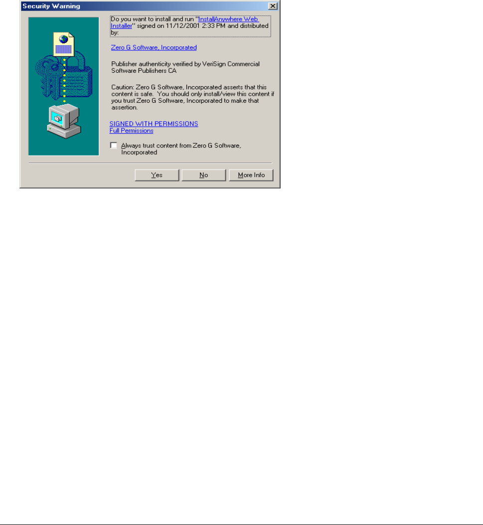
2. Double-click on the Install icon. Two windows open simultaneously: InstallAnywhere Web
Installer — Microsoft Internet Explorer (in disabled mode) superimposed by Security Warning
(in enabled mode).
Click the Yes button on the Security Warning window to close this window and view the Base Station
Configuration Software window.
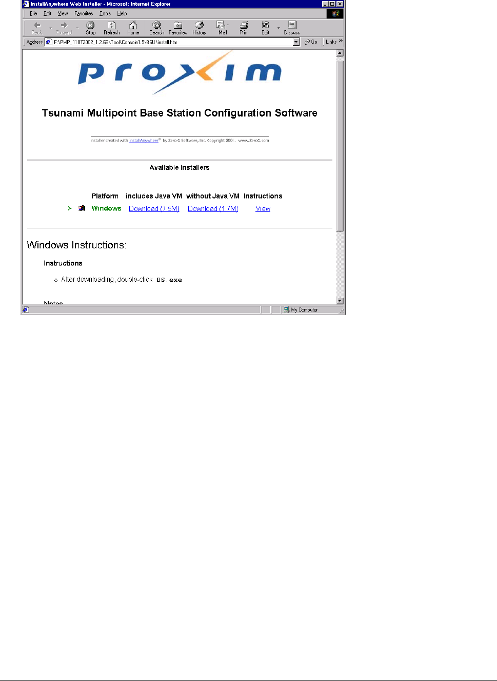
For the remainder of this procedure, only default settings are used. Select the applicable installer for
your network environment when performing these steps.
3. Click Download 7.5M to download the Tsunami Multipoint Base Station configuration software and
Java VM; click Download 1.7M to download the Tsunami Multipoint Base Station configuration
software without Java VM.
Appendix B. Installing the Software and Upgrading Firmware 52
CPN 63179 Issue Date: 01/24/03
Tsunami Multipoint Version 1.3 Installation Guide
After the download completes, double-click on BS.exe to begin installation.
When the Tsunami Multipoint Base Station Configuration Software Introduction window is
displayed; click Next.
4. Click Next on the Important Information window once you have completed reading the text. When
the License Agreement window is displayed, accept the terms of the License Agreement and click
Next to proceed with the installation.
5. Click the Next button after making your choices on the following windows:
º Choose Install Folder (you can select the default folder or specify another folder)
º Choose Java Virtual Machine (you can select the default machine or specify another machine)
º Pre-Installation Summary (summarizes the installation choices you have made)
6. When the Install Complete window is displayed, click on Done to return to the Web Installer
window; then close the Web Installer window.
Appendix B. Installing the Software and Upgrading Firmware 53
CPN 63179 Issue Date: 01/24/03

Tsunami Multipoint Version 1.3 Installation Guide
Subscriber Utility Software
System Requirements
Same as for Base Station Configuration Software (see “System Requirements” for the BSU on page 51).
Installing the Subscriber Utility Software
System requirements for the Subscriber Utility software are the same as for the Base Station
Configuration software.,
To install the utility software:
1. Identify the computer on which you plan to run the Subscriber Utility.
Note: See “System Requirements” for the BSU on page 51 for operating system and hardware requirements.
2. Insert the Tsunami MP CD (provided with the product) into the computer’s CD-ROM drive and open
the CD’s config software folder.
Note: If the computer has Microsoft IIS (Internet Information Services) running, disable or uninstall it before
running the Subscriber Utility.
3. Double-click SUSETUP.HTM or use a Web browser to open the file.
4. Place a checkmark next to the Include VM in download option to install Java Virtual Machine (VM).
Note: You need not add VM if your computer already has a version of VM installed.
5. Click the Start Installer for Windows button to begin the software installation.
6. Follow the on-screen instructions to install the software.
7. Click Done when the installation is finished to close the installer.
8. Launch the Subscriber Utility.
Firmware Downloads
Firmware can be downloaded to the BSU using the local console. Firmware can be downloaded to the SU
either over-the-air or from a local console (by attaching a PC with the Base Station Configuration
Software to the SU).
Proxim recommends you download new code as follows:
1. Download the new code to the SU’s and verify that they re-enter the network.
2. Next, download new code to the BSU.
Appendix B. Installing the Software and Upgrading Firmware 54
CPN 63179 Issue Date: 01/24/03

Tsunami Multipoint Version 1.3 Installation Guide
Remote Over-the-Air Download to SUs
You can upgrade your SUs to Version 1.3 from the Base Station Configuration Software Console of the
BSU. Normally, all SUs in the network are upgraded at the same time. However, if one or more SUs fail
to receive the download code correctly, the upgrade is aborted and a second attempt must be made. SUs
that have been upgraded successfully ignore reprogramming of the same codes.
To download remotely to SUs:
1. From the BSU 1.4 or 1.5 Console, confirm that SUs have established a link with the BSU by issuing a
dspActiveSU command. Make note of the SUs in the network.
2. Select the Download menu.
3. Select Remote Firmware; a Download — File Selection window is displayed.
4. From the Look In search field, select the binary file to be downloaded (PMP_SU_release1-3.mot)
from the appropriate directory. The BSU Console automatically processes the selected binary codes
and, once finished, displays an output of “Elapsed [time]” in seconds.
5. Let the SUs re-enter the network. It usually takes no more than five minutes for the SUs to enter the
network from the start of the download. The following messages are displayed at the BSU Console
for each SU as it enters the network:
º 118 Received NetEntry Request from Eth<SUs Ethernet address>
º 119 NetEntry completed: Assigned terminal ID <ID#>, IP<SUs IP address>, and VLAN ID
<SU VLAN ID#> in VLAN mode.
6. Issue dspActiveSU to verify that the SUs have entered the network successfully. If an SU fails to
enter the network, use the local download procedure in the following section.
º If the SU was correctly upgraded, the display reads ver 20021300.
º If the SU failed to upgrade and the link was restored, the display most likely reads ver
200212B0.
7. If any SU that re-entered the network failed to upgrade to Version 1.3, repeat steps 2 through 6, or
upgrade the failing SUs using the “Local Download to SUs” method.
Local Download to SUs
You can use this method to upgrade SUs that have not been deployed or have failed to successfully
download using the remote over-the-air procedure. Using this procedure, individual SUs are upgraded
through their Ethernet/Power cable. This procedure requires the Tsunami Multipoint Base Station
Configuration Software application be loaded on the PC attached to the SU (SU 1.,4 or 1.5 Console). The
window label appears as Tsunami Multipoint Subscriber Configuration Software.
Appendix B. Installing the Software and Upgrading Firmware 55
CPN 63179 Issue Date: 01/24/03

Tsunami Multipoint Version 1.3 Installation Guide
To download locally to an SU:
1. From the SU 1.4 or 1.5 Console, select the Download menu.
2. Select Local Firmware.
3. From the Look In search field, choose the binary file to be downloaded (PMP_SU_release1-3.mot)
from the appropriate directory and click Select. The download requires about 2 minutes. Once the
download is complete, the banner indicating Version 1.3 is displayed.
If the download does not complete successfully, as indicated by a checksum mismatch or a failure to
reboot, cycle power to the SU and repeat, starting at step 1.
Local Download to the BSU
Use this download method to upgrade BSUs after the SUs have been upgraded to Version 1.3. The BSU
is upgraded through its Ethernet/Power cable using the BSU 1.4 or 1.5 Console.
To locally download to the BSU:
1. From the BSU 1.4 or 1.5 Console, select the Download menu.
2. Select Local Firmware.
3. From the Look In search field, choose the binary file to be downloaded (PMP_BSU_release1-3.mot)
from the appropriate directory and click Select.
4. Once the upgrade is successful, if there were SUs connected to the BSU, they will re-acquire net
entry. For each SU connection, two messages are displayed:
º 120 Received NetEntry Request from Eth<SU’s Ethernet address>
º 121 NetEntry completed: Assigned terminal ID<ID#>, VLAN ID 1, IP<SU’s IP address>
It normally takes less than a minute and a half for the SUs to re-acquire NetEntry with the BSU from
the time the local download started.
5. If there were no SUs connected to the BSU, after the upgrade succeeds, the version banner is
displayed with version 20021300, following by three messages:
º 114 Completed flash sector verification
º 103 DB check completed
º 107 Save NV configuration Parameters
Once the SUs are re-connected to the BSU, expect the same behavior as specified in step 4.
Appendix B. Installing the Software and Upgrading Firmware 56
CPN 63179 Issue Date: 01/24/03

Tsunami Multipoint Version 1.3 Installation Guide
Appendix C. Technical Specifications
The following technical specification is for reference purposes only. Actual product performance and
compliance with local telecommunications regulations can vary from country to country. Proxim
Corporation only ships products that are type approved in the destination country.
Burst-Rate Limit
Product Burst-Rate Limit Model Number
Base Station Unit 60 Mbps
20 Mbps
40400-65 (also supports 20-40 Mbps burst rates)
40400-25
Subscriber Unit 60 Mbps
40 Mbps
20 Mbps
40100-65x (also supports 40-20 Mbps)
40100-45x (also supports 30-20 Mbps)
40100-25x
Downlink/Uplink Throughput
Burst Rate D/L Throughput U/L Throughput
20 Mbps 9 Mbps 8 Mbps
30 Mbps 13.5 Mbps 12 Mbps
40 Mbps 18 Mbps 16 Mbps
60 Mbps 27 Mbps 24 Mbps
Note: The above calculations are typical and based upon a 50/50 downlink (D/L) uplink (U/L) division of slots (see
“firstinboundSlot Command” in the Tsunami Multipoint Version 1.3 Reference Manual). SU throughput may
be limited by a provider’s Service Level Agreement or other D/L U/L settings.
Frequency Plans
The following table defines the frequencies associated with each plan.
Channel
Plan
Frequency
Channel
Plan
Frequency
Channel
Plan
Frequency
4A 5743.86 MHz 5A 5742.19 MHz 6A 5740.40 MHz
4B 5764.61 MHz 5B 5758.79 MHz 6B 5754.23 MHz
4C 5785.36 MHz 5C 5775.39 MHz 6C 5768.07 MHz
4D 5806.11 MHz 5D 5791.99 MHz 6D 5781.90 MHz
5E 5808.59 MHz 6E 5795.73 MHz
6F 5809.57 MHz
Appendix C. Technical Specifications 57
CPN 63179 Issue Date: 01/24/03
Tsunami Multipoint Version 1.3 Installation Guide
Tx Power
BSU .....................+6 to +17 dBm (into antenna port)
SU.......................-48 to +15 dBm (into antenna port)
Antenna
BSU .....................Integrated, LHCP (left-hand circular polarization) 18 dBi
SU.......................Integrated, LHCP 21 dBi
Receiver Sensitivity
Burst Rate Threshold
60 Mbps -77 dBm
40 Mbps -81 dBm
30 Mbps -86 dBm
20 Mbps -89 dBm
Maximum Distance Between Base Station and Subscriber Unit
BURST-RATE CLOS1 NLOS2
60 Mbps 3 miles/5 km 1.2 miles/2 km
40 Mbps 4 miles/6.6 km 2 miles/3.5 km
30 Mbps 5 miles/8.3 km 2.4 Miles/4 km
20 Mbps 6 miles/10 km 3 miles/5 km
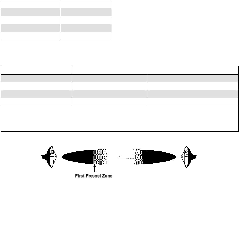
1Clear-Line-of-Sight distance is calculated for 99.995% availability assuming no obstructions in the first Fresnel
Zone.
2Near-Line-of-Sight distance is for a typical installation with moderate multipath/shadowing due to terrain and
structures.
Figure 29. Fresnel Zones
The Fresnel Zone refers to the radio beam. The radio signal’s path length and frequency determine the
Fresnel Zone’s width and shape. When a large part of the Fresnel Zone is blocked, some of the radio
signal’s energy is lost.
Appendix C. Technical Specifications 58
CPN 63179 Issue Date: 01/24/03

Tsunami Multipoint Version 1.3 Installation Guide
System
Operating Frequency Range............................ 5725-5825 MHz
Radio Access Method ..................................... TDMA
Duplexing .................................................... Time Division Duplex (TDD)
Integrated Antenna (BSU).............................. 19 dBi (60° Azimuth. X 6° Elevation) LHCP
Integrated Antenna (SU)................................ 20 dBi (10° Azimuth. X 10° Elevation) LHCP
Max Subscriber Units/BSU.............................. 1,023
Frequency Channels ...................................... 4 non-overlapping, 5 and 6 overlapping available
Regulatory Compliance .................................. FCC Part 15-400 (U-NII), IC RSS21 0
Standards Compliance and Interfaces
Ethernet Interface......................................... 10/100 Base-T
Ethernet Connector ....................................... RJ-45 female
BSU indoor-outdoor cable .............................. Circular plastic connectors with Category 5 cable
SU indoor-outdoor cable ................................ RJ-45 (outdoor) and DIN (indoor) over Cat 5 (UV) cable
Standards Compliance ................................... IEEE 802.1d Bridging Mode (a subset of the 802.d
standard)
IEEE 802.1q VLAN
Configuration and Management
BSU Configuration
Configuration ............................................... via Ethernet or Wireless Manager (future release)
SNMP.......................................................... AgentMIB II (future release)
Security ...................................................... Authentication, IP/MAC Filtering, passwords
Software Upgrades........................................ Downloadable Base Station reprogramming
SU Configuration
Configuration ............................................... Automatic
Security ...................................................... Authentication, IP/MAC Filtering
Software Upgrades........................................ Over-the-air Subscriber Unit programming
Appendix C. Technical Specifications 59
CPN 63179 Issue Date: 01/24/03

Tsunami Multipoint Version 1.3 Installation Guide
Power/Environment Safety
Electrical
Base Station Unit .......................................... -36 to –60 Volts DC, 1.25 Amps
Base Station Unit Power Brick......................... 100-240 Volts AC
Base Station Unit Power Block ........................ 48 Volts DC
Subscriber Unit............................................. 18 to 28 Volts DC, 0.8 Amps
Subscriber Unit Power Brick............................ 115 or 100-240 Volts AC
Operational Temperature
Indoor......................................................... 0° to 55° C
Outdoor....................................................... -33° to 65° C
Humidity
Indoor......................................................... 95% non-condensing
Outdoor....................................................... 5% to 100%, condensing
EIVIC .......................................................... FCC Class B
Safety ......................................................... UL-1950
Environmental Compliance ............................. ETS 300 019
Physical Dimension
Base Station (Outdoor Unit)
Size (WxHxD) .............................................. 10.2 x 24 x 6.6 inches/25.9 x 61 x 16.8 cm
Weight ........................................................ 20 lbs/9 kg
Base Station Power Block (Indoor Unit, for up to 6 Base Stations)
Size (WxHxD) .............................................. 17.2 x 3.5 x 8.25 inches/43.7 x 8.9 x 21 cm
Weight ........................................................ 5 lbs/2.3 kg
Base Station Power Brick (Indoor Unit, for 1 Base Station)
Size (WxHxD) .............................................. 37.4 x 70.9 x 24.8 inch/95 x 180 x 63 cm
Weight ........................................................ 1.5 lbs/0.7 kg
Appendix C. Technical Specifications 60
CPN 63179 Issue Date: 01/24/03

Tsunami Multipoint Version 1.3 Installation Guide
Subscriber Unit (Outdoor Unit)
Size (WxHxD) .............................................. 10.5 x 10.5 x 6.8 inches/26.5 x 26.5 x 17.4 cm
Weight ........................................................ 10 lbs/4.5 kg
Subscriber Unit Power Brick (Indoor Unit)
Size (SxHxD) ............................................... 36 x 5.1 x 2.6 inch/92 x 130 x 67 cm
Weight ........................................................ 2.7 lbs/1.2 kg
Installation Details
Base Station Unit (outdoor unit)...................... Pole mounting, 1.5-4.5” diameter
Subscriber Unit (outdoor unit) ........................ Pole mounting, 1.25-1.75” diameter
Optional Accessories
Base Station Unit
Connector kit ............................................... Part # ACC-5300
Subscriber Unit
Wall mounting kit ........................................ Part # ACC-40100
(contact factory for details)
Connector kit ............................................... Part # ACC-5200
Appendix C. Technical Specifications 61
CPN 63179 Issue Date: 01/24/03
Tsunami Multipoint Version 1.3 Installation Guide
Appendix D. Constructing Power and Ethernet Cables
Subscriber Unit Power and Ethernet Cable
Perform the following steps to construct a Subscriber Unit power and Ethernet cable of the desired length.
CAUTION For best results this cable should be constructed by professional cable
manufacturer or by experienced personnel with proper tools. Contact Proxim
Customer Service or Sales for recommendations for a manufacturer near your
vicinity.
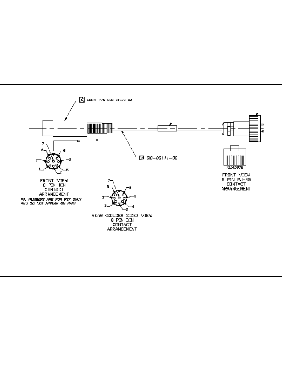
Figure 30. 8-Pin DIN and RJ45 Contact Arrangements
Perform the following steps to construct an interface cable of the desired length.
WARNING! Interface cable length should not exceed 75 m.
Required Materials
The following is a list of the materials required to assemble an interface cable.
▪ Cat 5 UV cable (75 meters maximum).
▪ One each 8-pin DIN male connector with cover (solder type) or one each 8-position DIN male
connector (crimp type).
▪ One each Woodhead weatherproof RJ45 connector.
Appendix D. Constructing Power and Ethernet Cables 62
CPN 63179 Issue Date: 01/24/03
Tsunami Multipoint Version 1.3 Installation Guide
Assembling the 8-Pin DIN Connector
To assemble the 8-pin DIN connector:
1. Slide the jacket of the 8-pin DIN connector over one end of the Cat 5 UV cable.
2. Prepare the Cat 5 cable ends by removing 0.75” of the main jacket. Do not cut the twisted pair
wires.
3. Remove 0.06” of insulation from the end of each wire in each twisted pair.
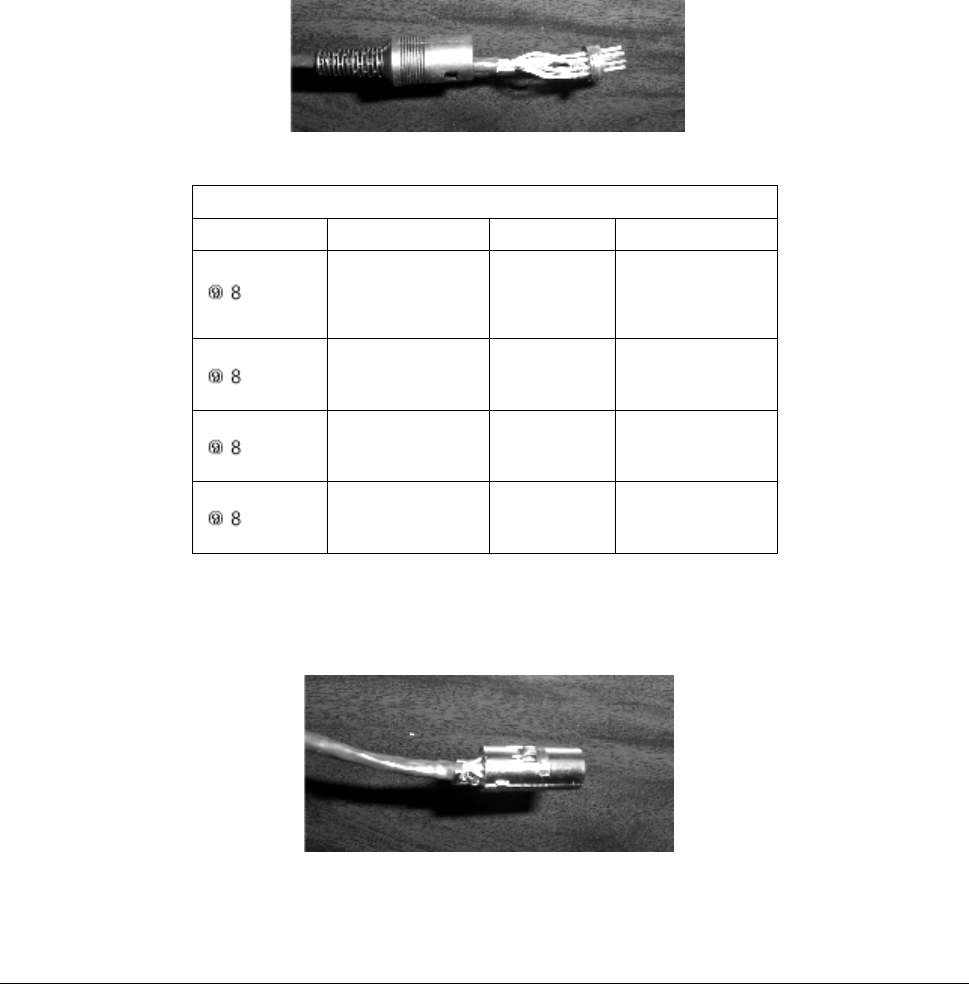
4. Solder each wire prepared in step 3 to the appropriate cup on the DIN connector. Refer to the
following table for information.
Figure 31. Soldered Wires on 8-Pin DIN Connector
Interface Cable Pin Assignments
DIN Pin Color Signal RJ45 Plug Pin
2
7
Orange
Orange/White
+24 VDC
- 24 VDC
4
5
6
8
Brown
Brown/White
+24 VDC
- 24 VDC
7
8
5
3
Green
Green/White
Tx+
Tx-
1
2
1
4
Violet
Violet/White
Tx+
Rx-
3
6
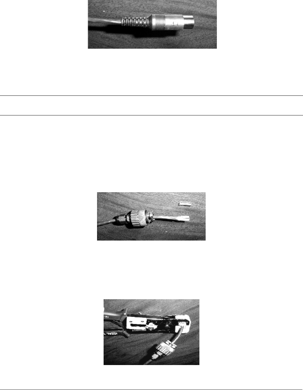
5. Assemble the metal shell over the DIN connector; make sure the DIN connector fits into the slots of
the metal shell.
Figure 32. Metal Shell Placed Over 8-Pin DIN Connector
Appendix D. Constructing Power and Ethernet Cables 63
CPN 63179 Issue Date: 01/24/03
Tsunami Multipoint Version 1.3 Installation Guide
6. Using small pliers, crimp the metal strain relief over the Cat 5 cable. Do not cut into the cable. Slide
the jacket over the completed assembly.
Figure 33. Jacket Placed Over 8-Pin DIN Connector
Assembling the RJ45 (Woodhead) Weatherproof Connector
CAUTION For best results this cable should be constructed by professional cable manufacturer or by
experienced personnel with proper tools. Contact Proxim Customer Service or Sales for
recommendations for a manufacturer in your vicinity.
To assemble the RJ45 (Woodhead) connector:
1. Slide the threaded Wooodhead cover over the bare end of the Cat 5 cable.
2. Slide the body of the Woodhead connector over the bare end of the Cat 5 cable.
3. Slide a rubber “O” ring over the ridge of the Woodhead connector’s body.
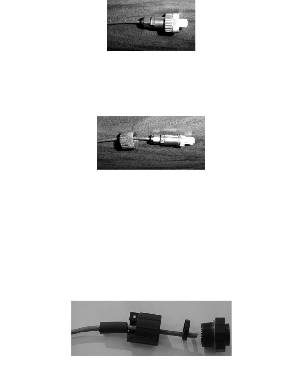
4. Remove 0.5” of jacket from the Cat 5 cable. Do not cut the wires of the twisted pairs.
Figure 34. Cat 5 Cable with Insulation Removed
5. Insert the ends of the twisted pairs into the RJ45 connector positioning wire color code (see the table
on the previous page).
6. Crimp the wires into the RJ45 connector using an RJ45 crimp tool.
Figure 35. Wires Crimped into RJ45 Connector
Appendix D. Constructing Power and Ethernet Cables 64
CPN 63179 Issue Date: 01/24/03
Tsunami Multipoint Version 1.3 Installation Guide
7. Slide the threaded Woodhead cover over the completed assembly and loosely tighten it down to the
cable.
Figure 36. Woodhead Cover Placed Over RJ45 Connector
8. When connecting the cable to an SU, insert the RJ-45 connector into the SU’s Power and Ethernet
port until the locking tang clicks, slide the Woodhead body over the RJ-45 connector until it is seated,
tighten the coupling nut to seal the connector to the housing, and tighten the gland to seal the
assembly to the cable.
Figure 37. End Nut Seated on RJ45 Connector
BSU Power and Ethernet Cable
This section describes how to construct a Power and Ethernet cable for a BSU. This cable has the
following connectors:
▪ 18-pin Positronic connector
▪ 8-pin AMP connector
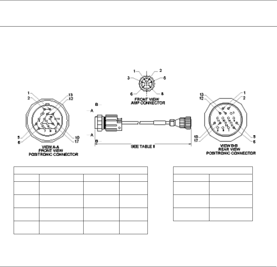
Installing an 18-Pin Positronic Connector
Perform the steps following the figure to install an 18-pin positronic connector on the cable.
Figure 38. 18-Pin Positronic Connector
Appendix D. Constructing Power and Ethernet Cables 65
CPN 63179 Issue Date: 01/24/03
Tsunami Multipoint Version 1.3 Installation Guide
1. Cut 750-00891-00 tubing or Proxim approved equivalent to 1.25" +/- 0.1".
2. Using silicone spray or equivalent lubricant, spray the end of the wire, then slide the tubing onto the
wire, approximately 4" out of the way.
3. Slide the backshell with the ½" (inside diameter) rubber cable seal onto the wire.
4. Crimp the connector pins onto the individual wires using a Positronic crimping tool 9507 (crimping
frame) and 9502-20 (die).
5. Insert the 1.9" (outside diameter) 1/8" wide plastic ring inside the rear of the connector.
6. Insert the crimped pin/wire assemblies in the appropriate holes in the rear of the connector.
7. Attach the backshell to the connector by threading it clockwise onto the connector.
Note: You need a FR19MF1822K0 connector plug (no pins required, housing only) to get a better grip on the
connector. A good grip is required to sufficiently torque the backshell to provide a good seal. When torquing
the backshell, make sure the CAT5 cable can still rotate freely inside the backshell so it does not get broken.
8. Using silicone spray, slide the tubing into the cable seal inside the backshell until it is flush with the
end of the connector.
9. Install the backshell clamp over the tubing and wire.
Table I - Wiring Table II – Cable Length
Pin Pos Color Signal AMP Pin Dash No Length
17
10
orange
white/orange
48VDC+
48VDC-
1
2
-01 25m-.1m
6
5
brown
white/brown
48VDC+
48VDC-
3
4
-02 50m-.1m
12
13
violet
white/violet
Rx+
Rx-
7
8
-03 75m-.1m
1
2
green
white/green
Tx+
Tx-
5
6
Figure 39. BSU Power and Ethernet Cable Connectors
Appendix D. Constructing Power and Ethernet Cables 66
CPN 63179 Issue Date: 01/24/03
Tsunami Multipoint Version 1.3 Installation Guide
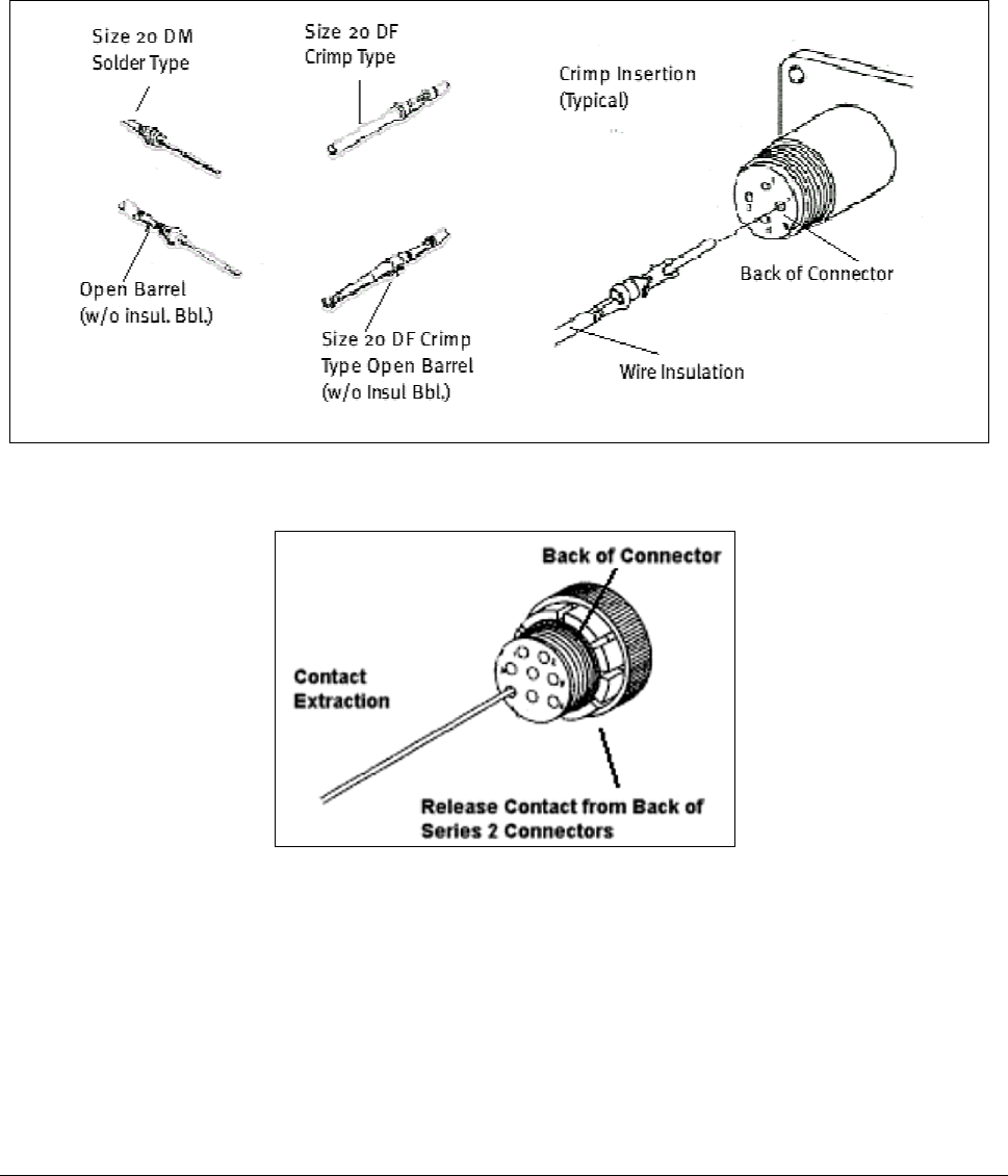
About Crimping
Loose piece contacts are designed to be crimped with crimp tooling (hand tools, die assemblies, or
crimping heads), but can be done with normal hand tools. The applicable crimp tooling for the contacts is
described later in this section. Read the documentation included with the crimp tooling for the proper
crimping procedure.
Figure 40. Crimping Styles and Insertion
Figure 41. Indoor Portion of Power and Ethernet Cable
Appendix D. Constructing Power and Ethernet Cables 67
CPN 63179 Issue Date: 01/24/03
Tsunami Multipoint Version 1.3 Installation Guide
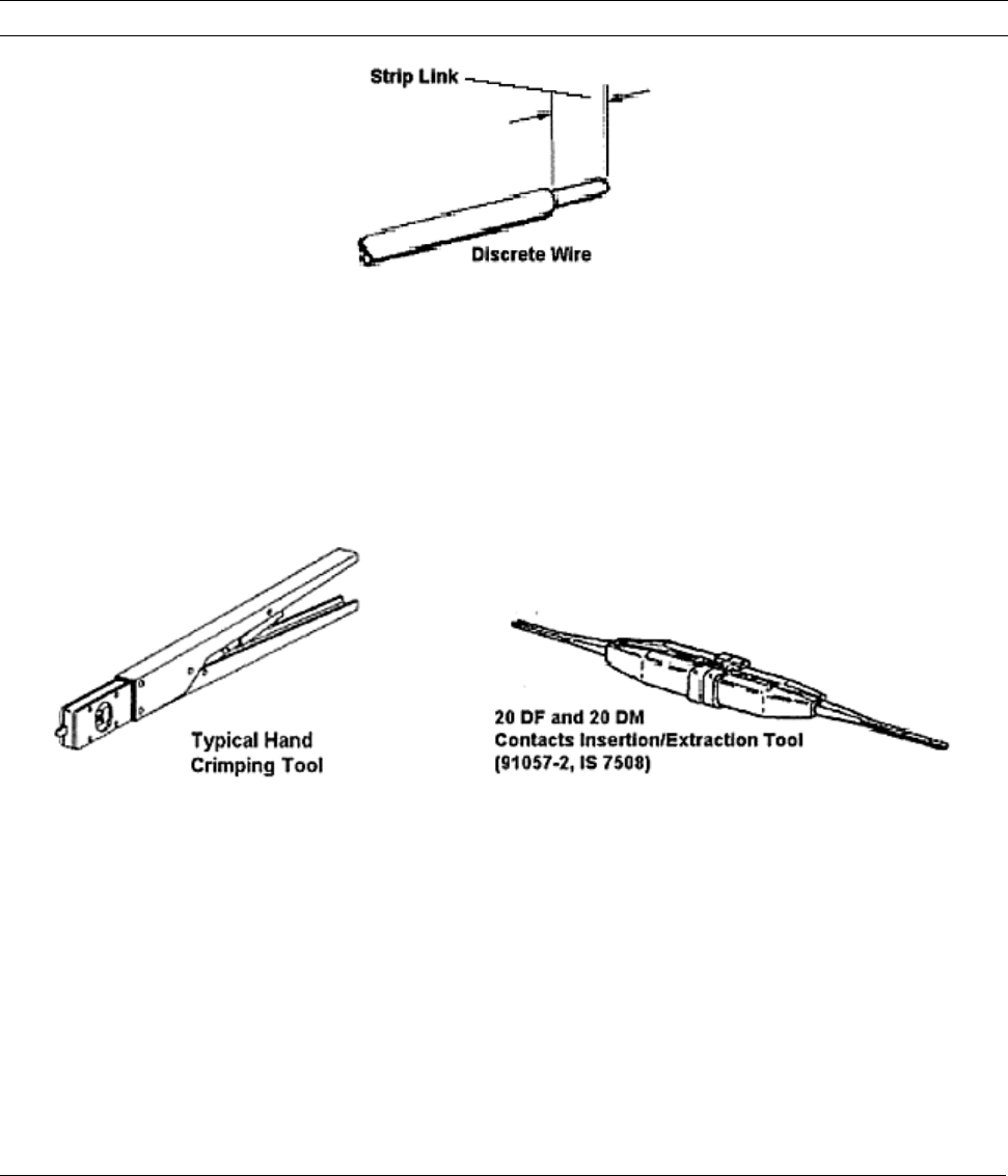
Wire Size and Preparation
Contacts are available for the wire sizes specified. Prepare the wire for crimping by stripping the
insulation. DO NOT nick, scrape, or cut the stranded or solid wire conductor while stripping the
insulation.
Note: When using twisted pair cable, cut one wire shorter than the other.
Figure 42. Wire Preparation
Tooling
AMP hand crimping tools and applicators are available for applying crimp type contacts. Also, insertion
and extraction tools assist in assembly and repair. See the documentation included with the tool for
more information.
Figure 43. BSU Cable Construction Tools
Appendix D. Constructing Power and Ethernet Cables 68
CPN 63179 Issue Date: 01/24/03
Tsunami Multipoint Version 1.3 Installation Guide
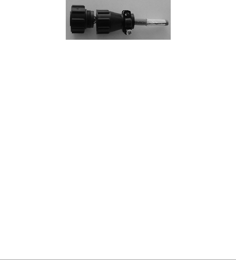
Installing the AMP CPC Connector with Shield and Strain Relief
The indoor end of the BSU Power and Ethernet cable uses an 8-pin circular plastic AMP connector with
crimp contacts. The connector is a reverse sex plug with male connector pins. The plug provided is not
weather tight and is meant for indoor use only. The connector uses a shield to cover the pin end of the
wires and has a strain relief clamp with two self-tapping screws to clamp the cable sheath to the
connector.
Figure 44. 8-Pin AMP Connector
To install the AMP CPC connector on the BSU Power and Ethernet cable:
1. Install the shield on the cable before removing the cable jacket. Slide the shield onto the cable so
that the threaded, large-diameter end faces the end of the cable.
2. Crimp the contacts to the wires according to the documentation included with the crimp tooling. Pins
are size 20 DM and the wire strip length is 0.100”.
3. Insert the contacts into the housing one at a time by gripping the insulation of the wire directly
behind the contact and aligning the contact with the back of the desired contact cavity.
4. Insert each contact straight into the cavity until it bottoms, then pull back lightly on the wire to be
sure the contact is locked in place.
5. Thread the shield onto the connector and tighten the shield finger-tight.
6. Screw in the strain relief over the end of the cable using the two supplied Phillips head screws.
Appendix D. Constructing Power and Ethernet Cables 69
CPN 63179 Issue Date: 01/24/03

Tsunami Multipoint Version 1.3 Installation Guide
Appendix E. Lightning Protection Recommendations
This appendix describes Proxim Lightning Protection Recommendations for:
▪ Tsunami Multipoint Base Station Unit 40400-25/-65
▪ Tsunami Multipoint Subscriber Unit 40100-251/-252/-651/-652
Introduction
What is Lightning Protection?
All outdoor electronic equipment is susceptible to lightning damage. Proper grounding to national and
local codes is instrumental in providing human safety. Lightning Protection is used when a customer
wants to maximize the reliability of the electronic system by diverting the excess energy that can be
induced on any transmission lines (data, power) through a series of surge protection devices. The energy
is dissipated through heat and also diverted to ground.
What Lightning Protection is Built Into the Tsunami Equipment?
All Tsunami Multipoint and QuickBridge equipment have built-in lightning protection on both the power
supply lines and the Ethernet lines. There are TVS diodes that provide protection to IEC 61000-4-5.
Proxim Corporation uses “well-design” practices in incorporating these devices in the Tsunami Multipoint
and QuickBridge products.
Why is Additional Protection Recommended?
Lightning, even with the built-in protection, can still damage outdoor Tsunami equipment. This can occur
for any number of reasons, such as an improperly grounded installation or if the amount of transient
energy from nearby lightning exceeds what the devices can handle.
If a Tsunami unit fails due to damage from lightning, the link is out-of-service until the unit is replaced or
repaired. An external, revertive protection device can provide a higher level of protection, and greater
probability of surviving lightning transients without damage to the Tsunami equipment. If damage does
occur, most likely it is to the lightning protection devices and not the Tsunami equipment. Remember,
even with external lightning protection, damage can still occur to the Tsunami outdoor unit.
Appendix E. Lightning Protection Recommendations 70
CPN 63179 Issue Date: 01/24/03

Tsunami Multipoint Version 1.3 Installation Guide
Recommendation
Proxim recommends the following for its Tsunami Multipoint products:
Installation Requirement
Proxim Product Industrial Commercial SOHO
Tsunami Multipoint Base Station Unit (BSU)
20/60 Mbps Models
(1) (1) (1) or
(2) (up to 50 meters)
Tsunami Multipoint Subscriber Unit (SU)
20/40/60 Mbps Models
(1) (1) or
(2) (up to 50 meters)
(1) or
(2) (up to 50 meters)
(1) PolyPhaser 101-1218W-A.1 CAT5 Data Protector
PolyPhaser Corporation
2225 Park Place,
Minden, Nevada 89423
(2) Transtector 1101-TSU Surge Supressor
Transtector Systems, Inc.
10701 Airport Drive
Hayden Lake, ID 83835
PolyPhaser CAT5 Data Protector
This is a heavy-duty aluminum, weather-tight enclosure for outdoor use that serves to protect the
Tsunami outdoor unit, as well as the indoor power adapter and connected line equipment inside the roof
penetration. This product can be used for all CAT5 cable lengths up to 100 meters from the outdoor
Tsunami unit to the indoor power adapter.
The Polyphaser Data Protector uses Cascade Technology. This is a multi-stage technology that is
superior to single stage because of high surge current capacity and fast response time. The unit is
designed to fit in-line onto the outdoor Cat 5 cable, using two weatherized plug openings for the cable to
enter and exit. The existing cable is cut, dressed, and reconnected onto two sets of 8 screw terminals
inside the Data Protector.
List Price: $209/ea.
Delivery: Available from authorized Proxim reseller or installer off-the-shelf.
Appendix E. Lightning Protection Recommendations C-
CPN 63179 Issue Date: 01/24/03
71
Tsunami Multipoint Version 1.3 Installation Guide
Transtector Systems Surge Supressor
This outdoor-use, molded plastic, weather-tight enclosure is a surge suppressor designed to protect the
Tsunami Multipoint SU and the QuickBridge unit from lightning damage. This product can be used for
CAT5 cable lengths up to 50 meters from the outdoor Tsunami unit to indoor power adapter.
The 1101-TSU uses silicon avalanche suppression diodes (SASD) to provide lower voltage protection level
(VPL). This technology provides a superior protection level over traditional gas tube type devices. The
unit is designed to fit onto a CAT5 cable in a pass-through configuration. The input and output
connections can be made at two sets of 8-screw terminals, or two 8-pin DIN style connectors.
This arrangement allows the installation of the connectorized Cat 5 cable directly into the Surge
Suppressor, or with a cut cable.
List Price: $99/ea.
Delivery: Available from authorized Proxim reseller or installer off-the-shelf.
Physical Considerations
How are the Lightning Protection Units Connected to the CAT5 Cable?
The lightning protection units recommended are designed to be installed in-line onto the Cat 5 cable that
connectors the outdoor (RF) Tsunami unit (Base Station, Subscriber Unit, QuickBridge) and the indoor
power adapter.
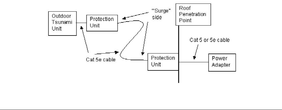
The lightning protection device has a Surge (cable-facing) side, and an Equipment (equipment-facing)
side. The Equipment side faces the outdoor Tsunami unit or the indoor power adapter. The Surge side
faces the long length of cable; when installing two lightning protection units, each unit’s Surge side face
one another.
See Pin-out information for each unit in “Lightning Protection Specifications” on page 73 for connecting
the cable to the protection device.
Appendix E. Lightning Protection Recommendations C-
CPN 63179 Issue Date: 01/24/03
72

Tsunami Multipoint Version 1.3 Installation Guide
Where Should the Protection Units be Located?
At least one unit should be installed near every outdoor Tsunami unit. General guidelines are:
▪ Locate protection unit as close to the outdoor Tsunami unit as possible, where the lightning protection
unit can be securely mounted to a flat surface and grounded properly. Ideally, this should be no
further than five feet away from the outdoor unit.
▪ Locate one unit at the roof penetration point, outside, so that the cable immediately enters the
building after the protection unit. This unit is optional if the distance from the first unit to the roof
penetration point is relatively short (under 15 feet).
Installing two units provides the maximum protection against lightning damage to the outdoor Tsunami
unit and the indoor power adapter, especially if the CAT5 cable length is greater than 15 meters.
Lightning Protection Specifications
PolyPhaser 101-1218W-A.1 Data Protector
Surge: BellCore 1089 10/100µsec, 100A
Temperature: -40°C to +65°C storage/operating +50°C
Maximum Characteristics Data:
Turn-on: +7.0 VDC ± 10%
Resistance: 1 ohm
Capacitance: 15 pf Line to Ground, 30 pf Line to Line
Data Rage: Up to 100Mbps (100BT)
Maximum Characteristics DC:
Turn-on: ± 68 VDC ± 10%
Resistance: 0.02 ohm
User Current: 2A max.
Size L x W x T: 6.53” x 2.77” x 1.25”
Appendix E. Lightning Protection Recommendations C-
CPN 63179 Issue Date: 01/24/03
73

Tsunami Multipoint Version 1.3 Installation Guide
Pinout and Wiring Specifications:
Surge Side Equipment Side Application Wire Color
Vdc in VDC out 48Vdc White/Orange
RTN in RTN out Ground Orange
Vdc in VDC out 48Vdc White/Brown
RTN in RTN out Ground Brown
Tx+ in Tx+ out Tx + Green
Tx- in Tx- out Tx - White/Green
Rx+ in Rx+ out Rx + Violet
Rx- in Rx- out Rx - White/Violet
GND GND Shield, if req. N/A
Note: VDC in (out) and RTN in (out) pinouts are based upon applying a negative or positive 48 FDC to the VDC
terminal and applying the dc ground to RTN.
For additional information, go to www.polyphaser.com.
Contact Information:
Polyphaser Corporation (702) 782-2511
2225 Park Place (702) 782-4476 (fax)
P. O. Box 9000
Minden, Nevada 89424
Transtector Systems ALPU-TSU Surge Suppressor
Surge: .......................................................IEEE 10/1000 Long Wave, 150 A peak
Temperature:..............................................-40°C to +80°C operating and storage
Ethernet Characteristics:
Transfer Rate: .............................................CAT5
Maximum Continuous Operating Voltage: ........ 20 VDC
Protection Mode: .........................................Line to Line, Line to Ground
Response Time (max): .................................5 nanoseconds
Standby Power (max):..................................<0.5 Watt
Peak Power:................................................5000 Watts
DC Characteristics:
Service Voltage: ..........................................20 VDC
Maximum Continuous Operating Voltage: ........ 80 VDC
Response Time (max): .................................5 nanoseconds
Standby Power (max):..................................<0.5 Watts
Peak Power:................................................ 20,000 Watts
Protection Mode: .........................................Line to Line
Size:..........................................................L x W x T: 6.13” x 4.5” x 2.5”
Appendix E. Lightning Protection Recommendations C-
CPN 63179 Issue Date: 01/24/03
74

Tsunami Multipoint Version 1.3 Installation Guide
Pinout and Wiring Specifications:
Surge Side Equipment Side Application Wire Color
VDC in VDC out 48 VDC White/Orange
RTN in RTN out Ground Orange
VDC in VDC out 48 VDC White/Brown
RTN in RTN out Ground Brown
Tx+ in Tx+ out Tx + Green
Tx- in Tx- out Tx - White/Green
Rx+ in Rx+ out Rx + Violet
Rx- in Rx- out Rx - White/Violet
GND GND Shield, if req. N/A
For additional information, go to www.transtector.com.
Contact information:
Transtector Systems (208) 762-6069
OEM Division (208) 752-6155 (fax)
10701 Airport Drive oem@transtector.com
Hayden Lake, ID 83858
Appendix E. Lightning Protection Recommendations C-
CPN 63179 Issue Date: 01/24/03
75

Tsunami Multipoint Version 1.3 Installation Guide
Appendix F. Technical Support and Training
If you are having a problem using a Tsunami Multipoint and cannot resolve it with the information in
“Appendix A. Troubleshooting” in the Tsunami Multipoint Version 1.3 Reference Manual, gather the
following information and contact Proxim Technical Support:
▪ What kind of network are you using?
▪ What were you doing when the error occurred?
▪ What error message did you see?
▪ Can you reproduce the problem?
You can reach Proxim Technical Support by phone, fax, e-mail, or mail:
Tel: 1-408-542-5390 (International)
Fax: 1-408-731-3673
Web: http://www.proxim.com/
E-mail: support@wmux.com
FTP: ftp.wmux.com (to download software)
Proxim Corporation
Attn: Technical Support
510 DeGuigne Drive
Sunnyvale, CA 94085
In addition, Proxim offers technical training courses across the United States throughout the year that are
designed to teach customers how to maximize the benefits of Proxim products. These classes are taught
by experienced Proxim Systems Engineers and have a technical focus. For class and registration
information, visit this Web site at http://www.wmux.com.
Be sure to obtain an RMA number before sending any equipment to Proxim for repair.
Appendix F. Technical Support and Training 76
CPN 63179 Issue Date: 01/24/03