Proxim Wireless S58-GX1 Unlicensed DTS User Manual Lynx
Proxim Wireless Corporation Unlicensed DTS Lynx
Contents
Manual Pages 54 55
Lynx.GX Installation and Management
PLANNING FOR ANTENNA AND RF TRANSMISSION LINE INSTALLATION
In general, the larger the antenna used with the radio, the better the link performs. Larger antennas have
narrower beamwidth and higher gain, which yield better link performance (higher fade margin, better availability)
and improve immunity to interference (due to the narrower beamwidths). This is especially important for multi-link
installations (hub sites) and for locations with potential interference sources nearby.
However, larger antennas are more costly to purchase and install than smaller antennas and, in some cases,
require special installation equipment and more robust mounting structures (due to increased weight and wind
loading). You should consider all of these factors when selecting an antenna.
Prior to installation, determine the specific antenna location and mounting. The transmission line should be kept
as short as possible, so when line-of-sight placement of antennas allow flexibility, it is always desirable for the
equipment to be located closer to the antenna.
This advanced planning, combined with the decision about where the RFU is to be mounted, yields the
transmission line requirements.
Note: In areas where transmitted output power restrictions apply, the use of larger antennas benefits narrow
beamwidths and receive gain. However, you could be required to reduce output power to meet
regulations. Only directional antennas should be used with these radios; typically flat-panel or solid-
parabolic antennas. As a general guideline, Proxim Corporation recommends a maximum 3 dB
beamwidth of 10 degrees for directional systems.
The following tables list various transmission lines, and then antenna types, performance, and manufacturers.
Within the USA and Canada, antennas other than those illustrated in these tables can be used with this radio,
but must be of the same type (flat panel or solid parabolic), dimensions, and gain as those listed in the table.
Antennas with gain less than 23.5 dBi are not approved for use within the USA or Canada. Consult
governmental regulations or Proxim Corporation for applications outside of the USA or Canada.
For further information regarding antenna installation and adjustment, see “Installing and Adjusting the Antenna”
on page 18.
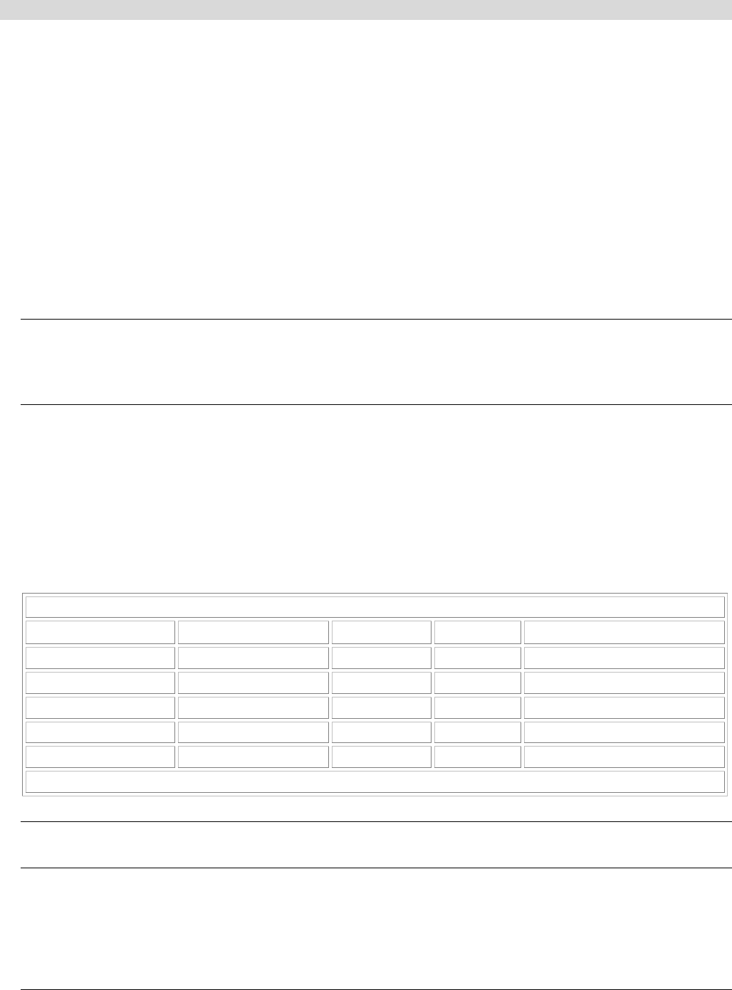
RF Transmission Line (Antenna to RFU)
Type Manufacturer Model
Loss* Notes
½-inch foam coaxial Andrew LDF 4-50 6.1 dB Add –0.25 dB per connector
5/8-inch foam coaxial Andrew LDF 4.5-50 4.7 dB Add –0.25 dB per connector
Waveguide Andrew EW-52 1.2 dB Does not include transitions
½-inch foam coaxial Times Microwave LMR-600 7.3 dB Add –0.25 dB per connector
5/8-inch foam coaxial Times Microwave LMR-900 4.9 dB Add –0.25 dB per connector
* per 100 ft. @ 5.8 GHz RF Frequency
Note: Due to potential moding problems, the use of 7/8-inch coaxial cable is NOT recommended for use with
these radios above 5 GHz.
Appendix A. Installation Planning 54

Lynx.GX Installation and Management
Antenna Manufacturer Information
Antenna Type Manufacturer Model Number Mid-Band Gain (dBi)
1-foot flat panel Tripoint Global
Andrew
RFS
DFPD1-52
FPA5250D12-N
MA0528-23AN
23.5
23.6
23.0
2-foot flat panel Tripoint Global
Andrew
RFS
DFPD2-52
FPA5250D24-N
MA0528-28AN
28.0
28.2
28.0
2-foot parabolic Tripoint Global
Tripoint Global
Radio Waves
Andrew
RFS
QF2-52
HQF2-52
SP2-5.2
P2F-52
SPF2-52A
28.5
28.1
28.3
29.4
27.9
3-foot parabolic Radio Waves
Andrew
RFS
SP3-5.2
P3F-52
SPF3-52A
31.4
33.4
31,4
4-foot parabolic Tripoint Global
Tripoint Global
Andrew
Radio Waves
RFS
RFS
QF4-52
HQF4-52
P4F-52
SP4-52
SPF4-52A
SDF4-52A
34.2
33.9
34.9
34.6
33.9
33.9
6-foot parabolic Tripoint Global
Tripoint Global
Radio Waves
Andrew
RFS
RFS
QF6-52
HQF6-5
SP6-5.2
P6F-52
SPF6-52A
SDF6-52A
37.5
37.2
37.7
37.6
37.4
37.4
8-foot parabolic Tripoint Global
Tripoint Global
SSP8-52A
HSSP8-52
39.8
39.6
The formula for determining maximum output power setting for 5.725-5.850 GHz Radio Transmitters
(@EIRP=54.5 dBm) is:
Max Tx (dBm) is the lesser of 24.5 dBm and 54.5 - G + FL
where:
G = Antenna Gain
Tx = the output power measured at the antenna input
FL = feeder loss including loss of connectors
Note: EIRP shall never exceed 54.5 dBm. This is for the compliance to the CFR 47 Part 1.1310 for RF
exposure.
Appendix A. Installation Planning 55