Proxim Wireless U53-45 UNII Radio User Manual 3 1 Shipping Container
Proxim Wireless Corporation UNII Radio 3 1 Shipping Container
UserManual.wiki
>
Proxim Wireless
>
U53-45 User Manual
>
User manual
Contents
1.
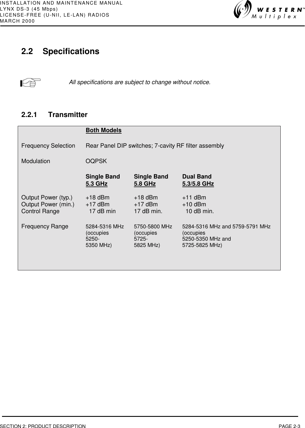
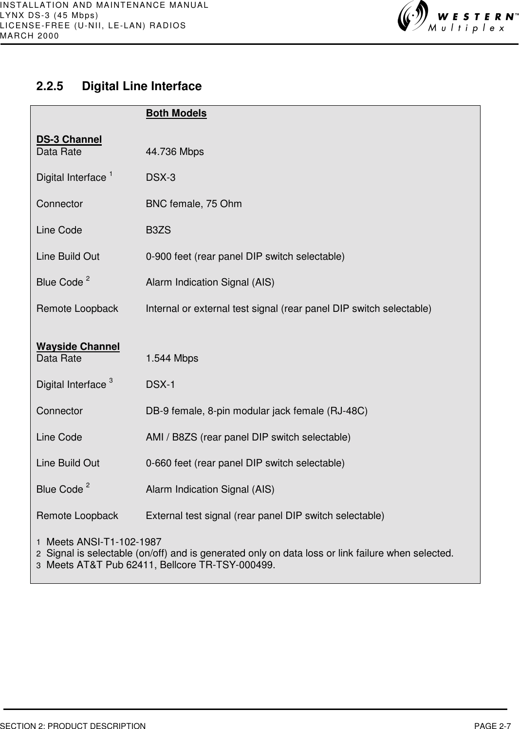
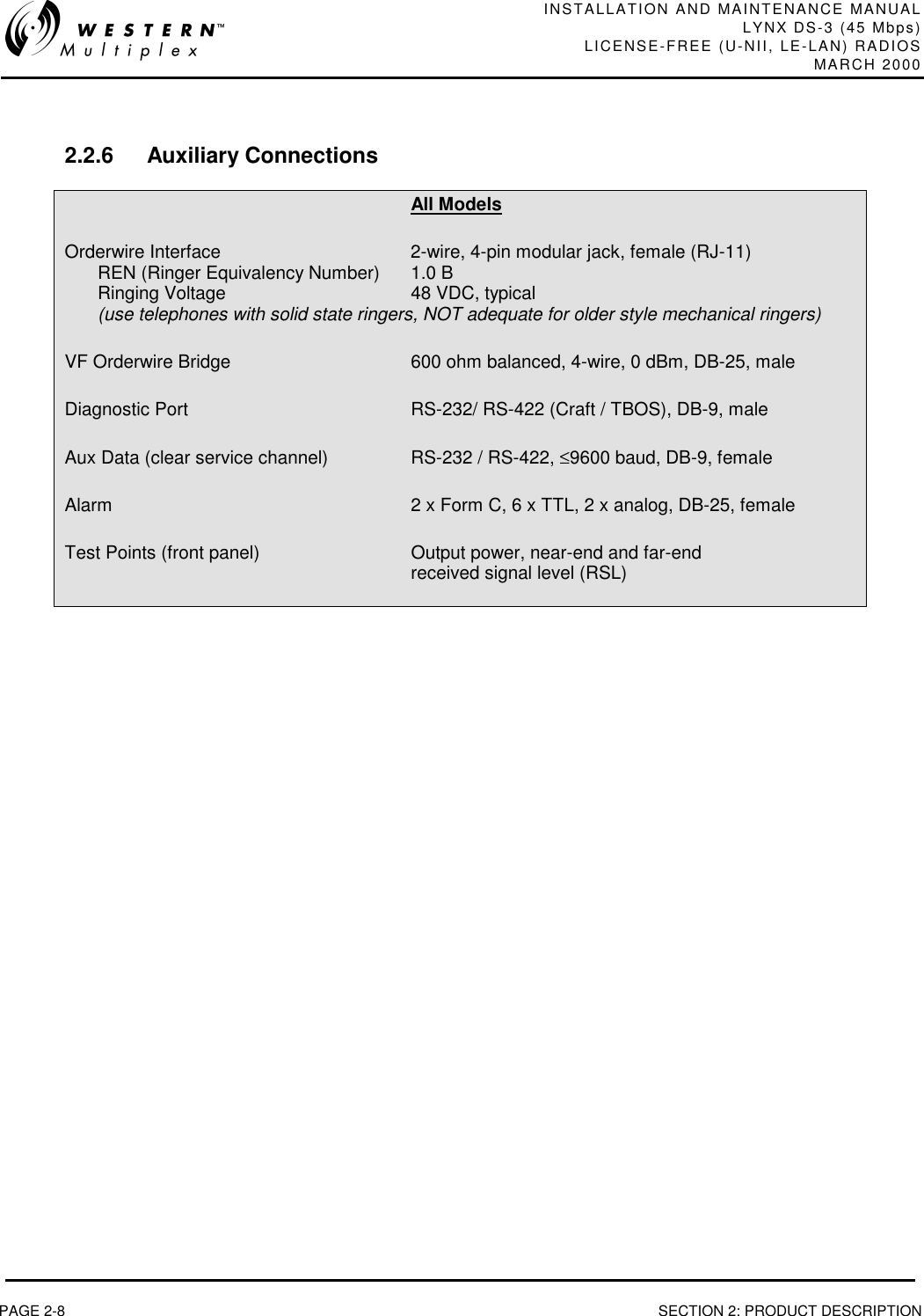
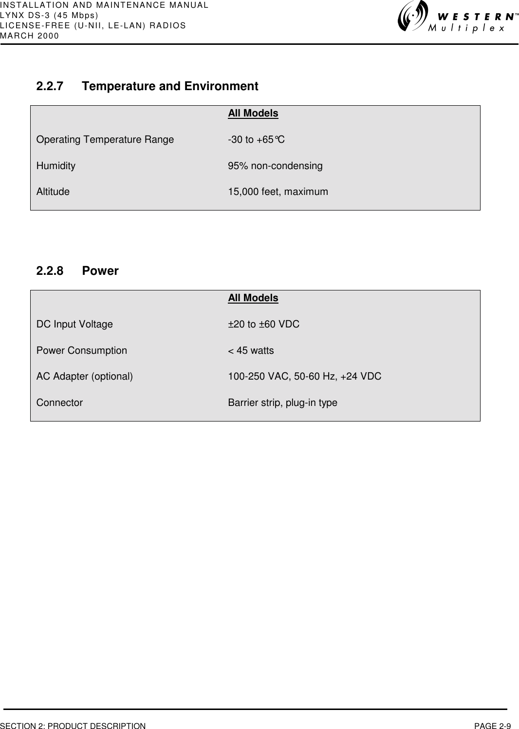
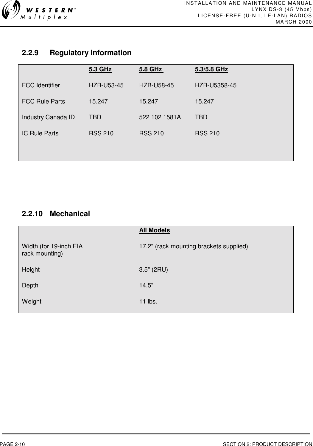
User manual
2.
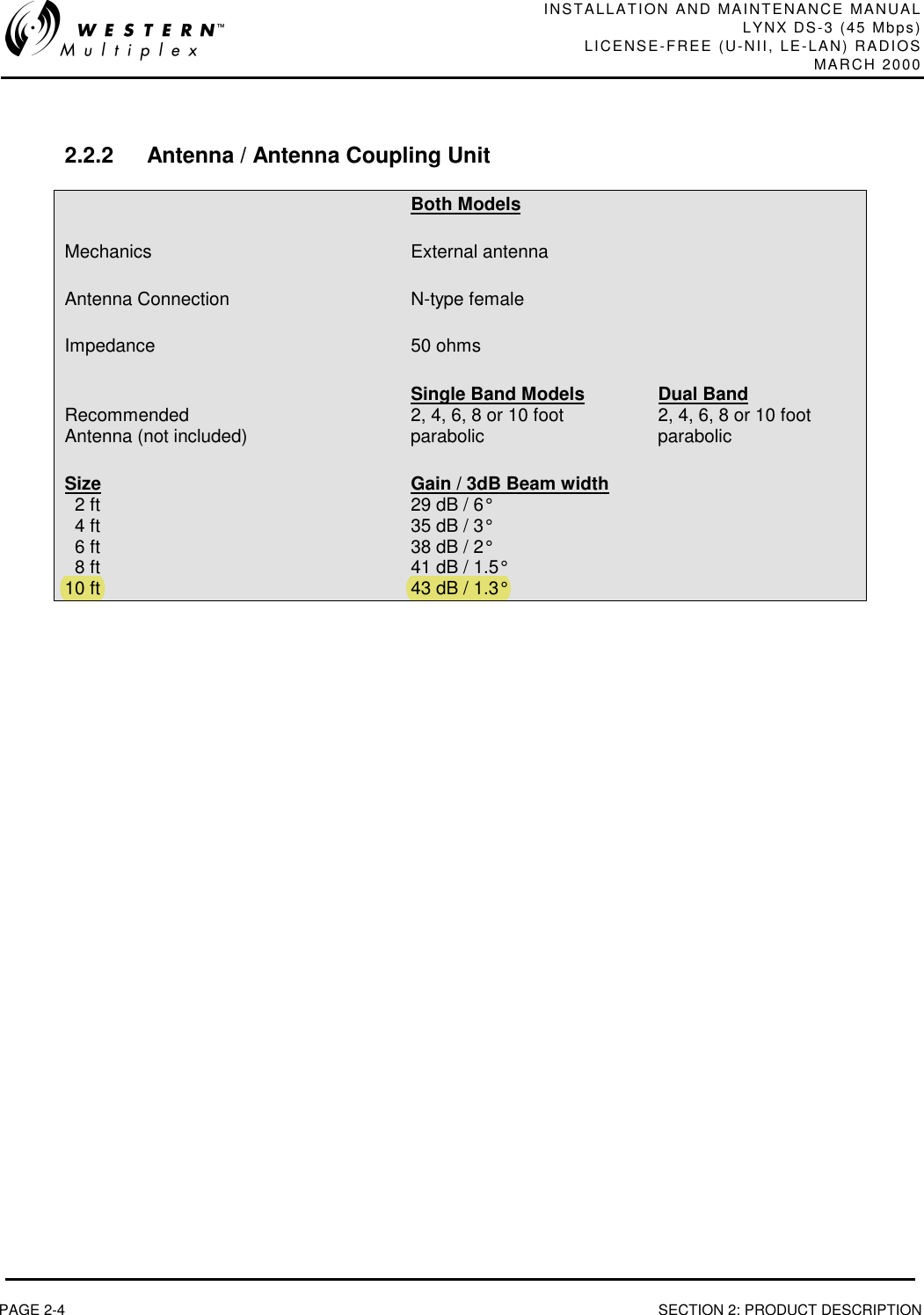
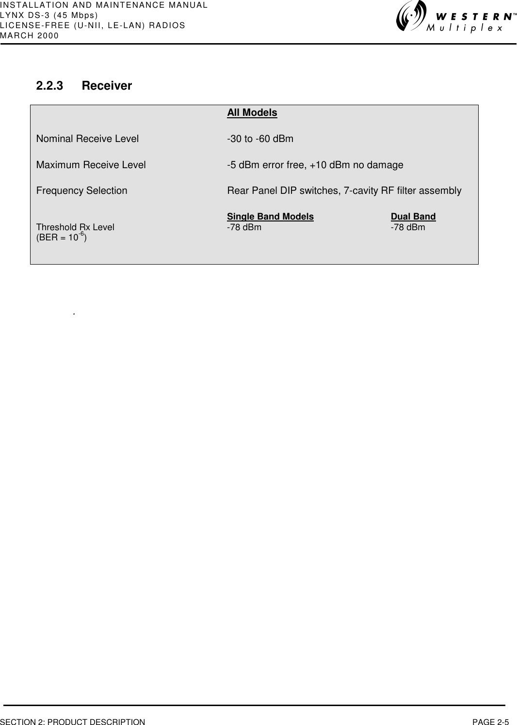
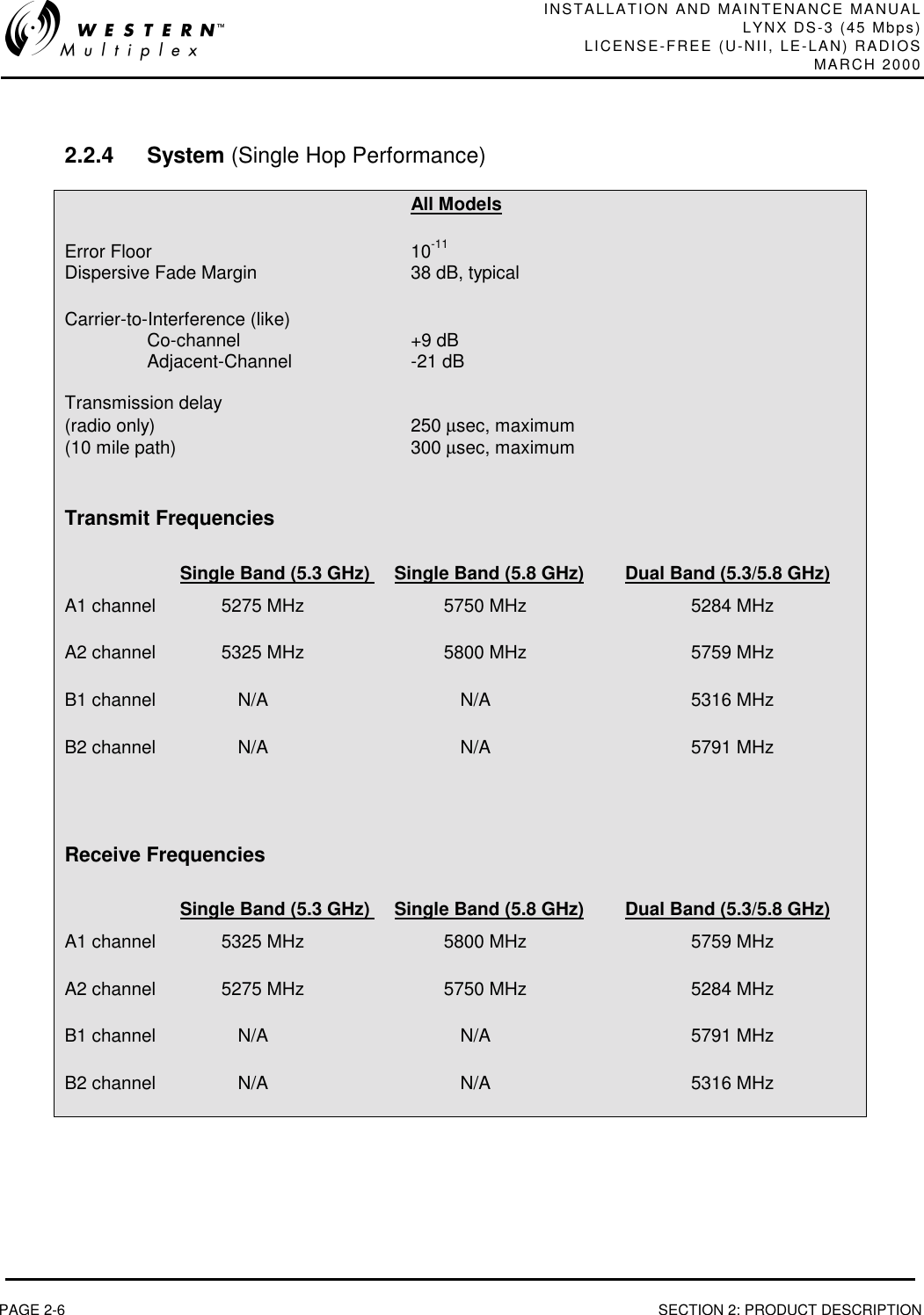
Antennas and power settings
User manual
Navigation menu
Upload a User Manual
Namespaces
Wiki Guide
HTML
PDF
Info
Views
User Manual
Discussion / Help
Navigation


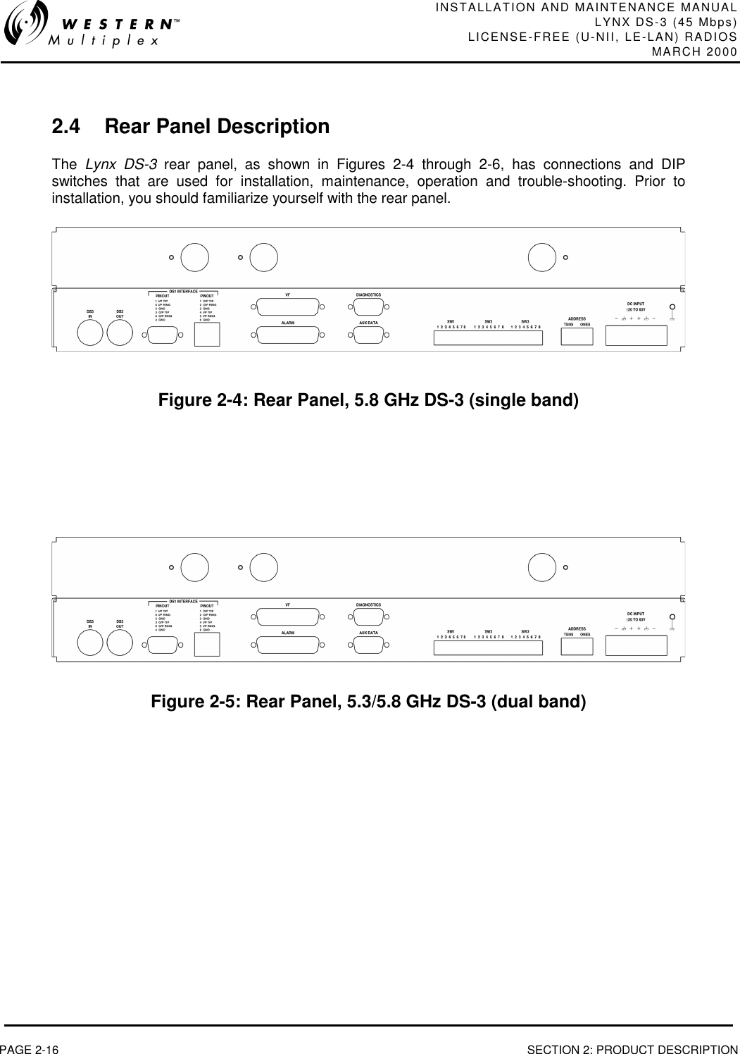
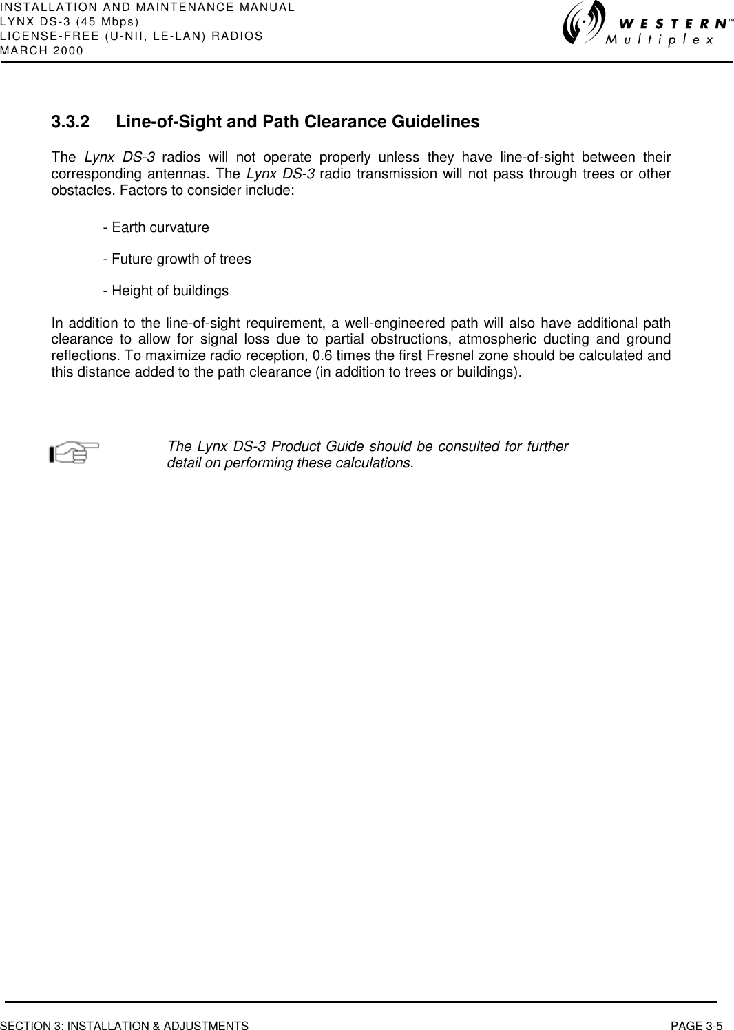
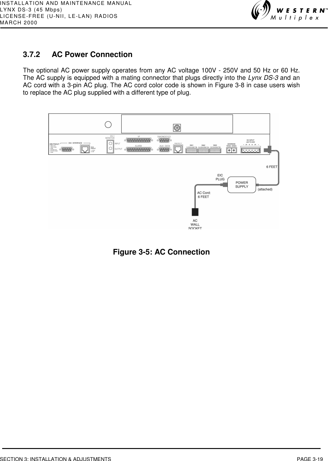
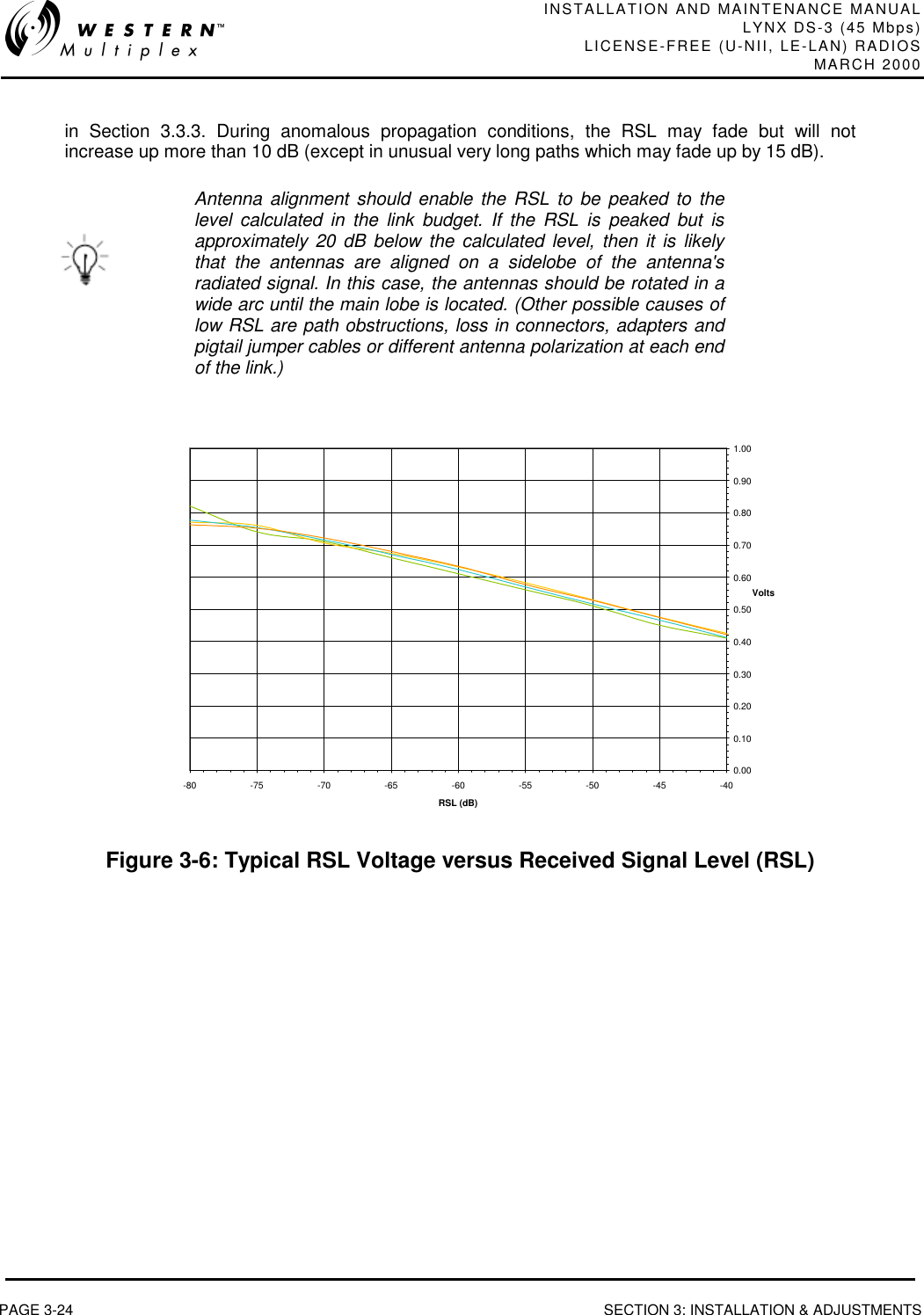
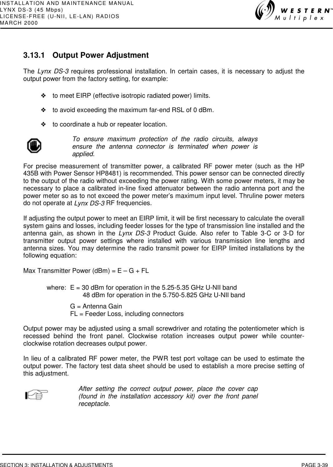
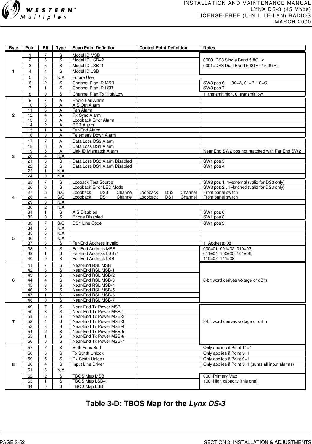
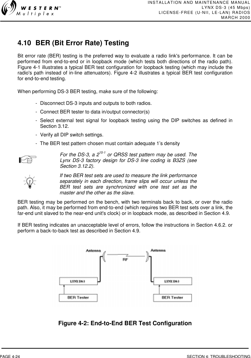
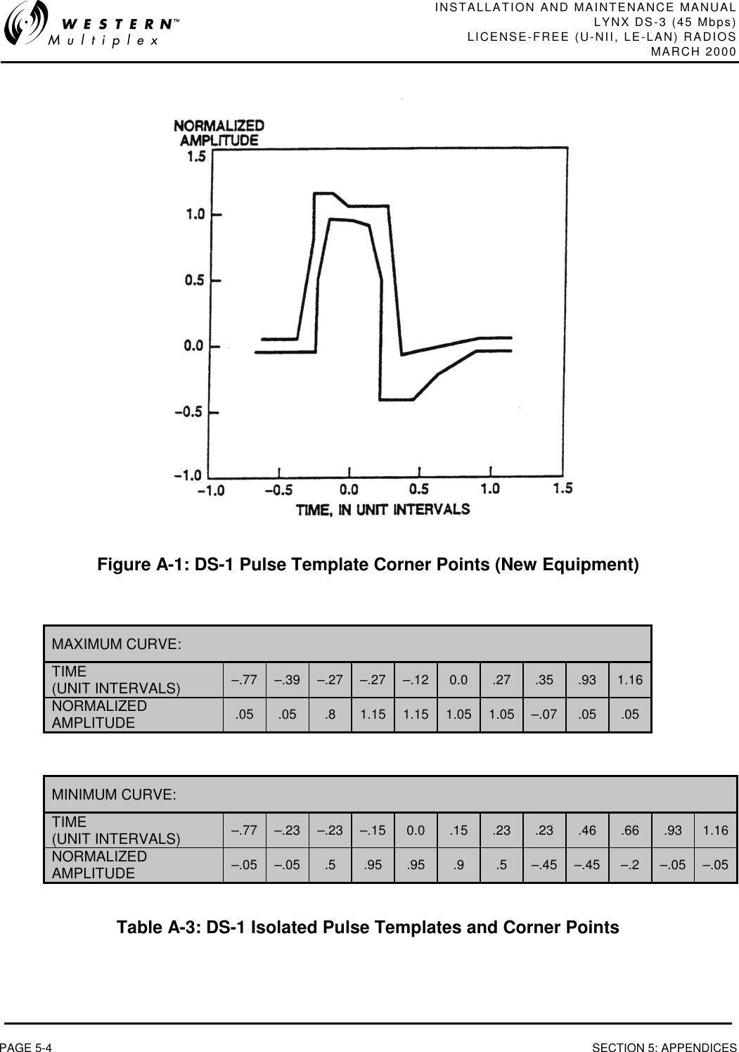
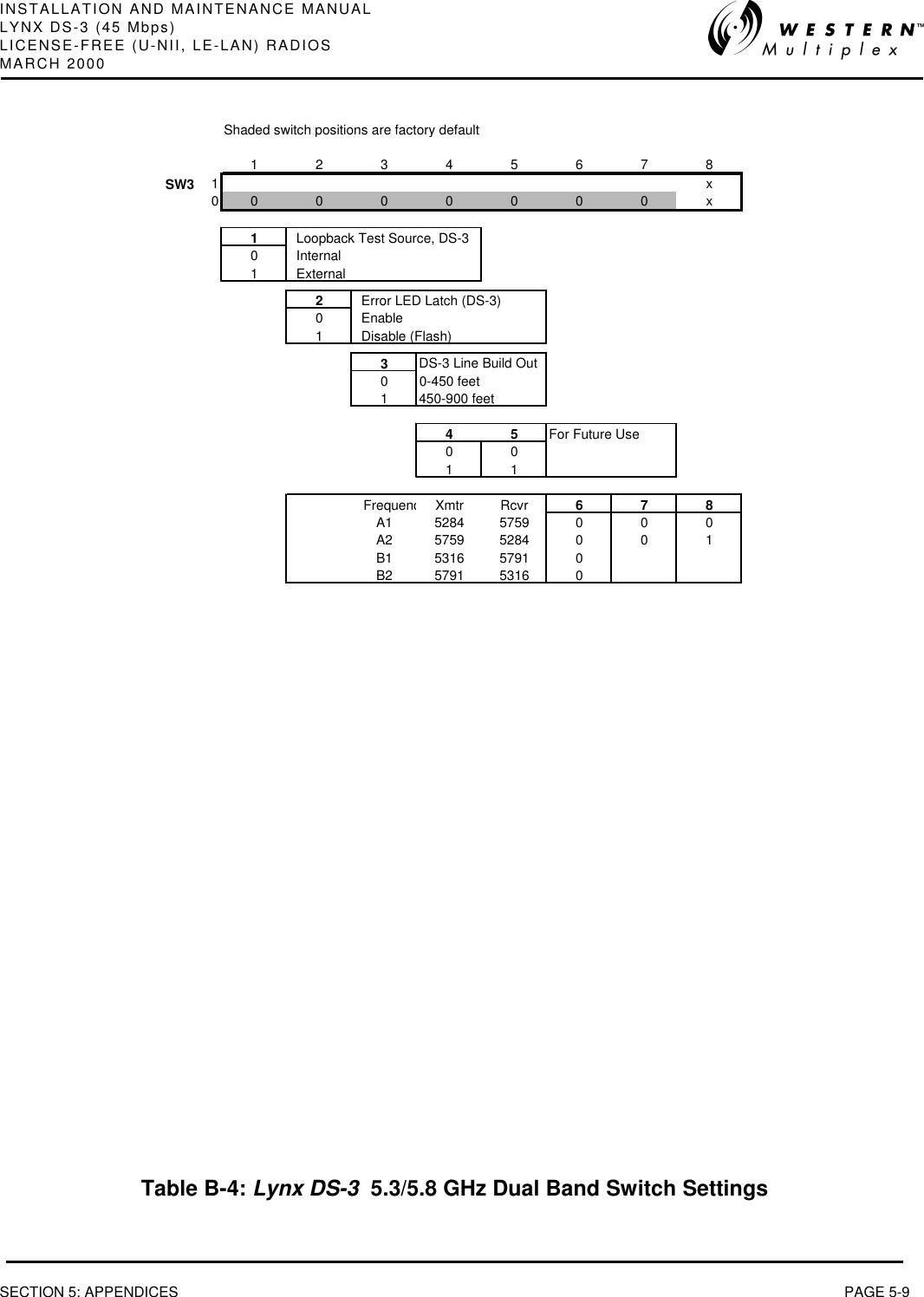
![INSTALLATION AND MAINTENANCE MANUALLYNX DS-3 (45 Mbps)LICENSE-FREE (U-NII, LE-LAN) RADIOSMARCH 2000SECTION 2: PRODUCT DESCRIPTION PAGE 2-152.3.5 ConnectionsORDERWIREThis connection is used to access the orderwire function. This is a facility for "telephone" styleservice from one radio to another. A standard electronic telephone [one with a handset and DTMF(push-button tone) dialing] plugs into this connector. The user can dial the orderwire address ofthe far-end radio (or any radio in the Lynx DS-3 network) to establish telephone communicationbetween sites. This communication does not interrupt or interfere with the other radiocommunications. The radio link must be operational to use this facility. The orderwire feature canbe very useful for installation, maintenance and troubleshooting.](https://usermanual.wiki/Proxim-Wireless/U53-45.User-manual/User-Guide-153198-Page-31.png)