Proxim Wireless U5358-100 U-NII Radio User Manual
Proxim Wireless Corporation U-NII Radio
UserManual.wiki
>
Proxim Wireless
>
U5358 100 User Manual
user manual
Navigation menu
Upload a User Manual
Namespaces
Wiki Guide
HTML
PDF
Info
Views
User Manual
Discussion / Help
Navigation

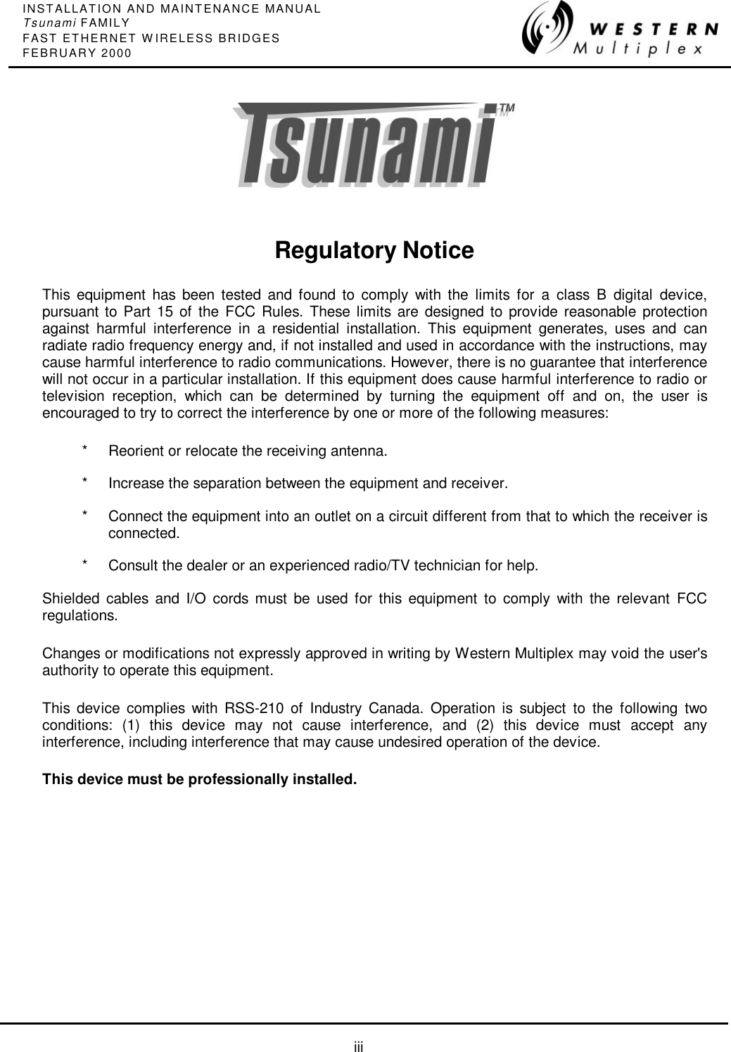

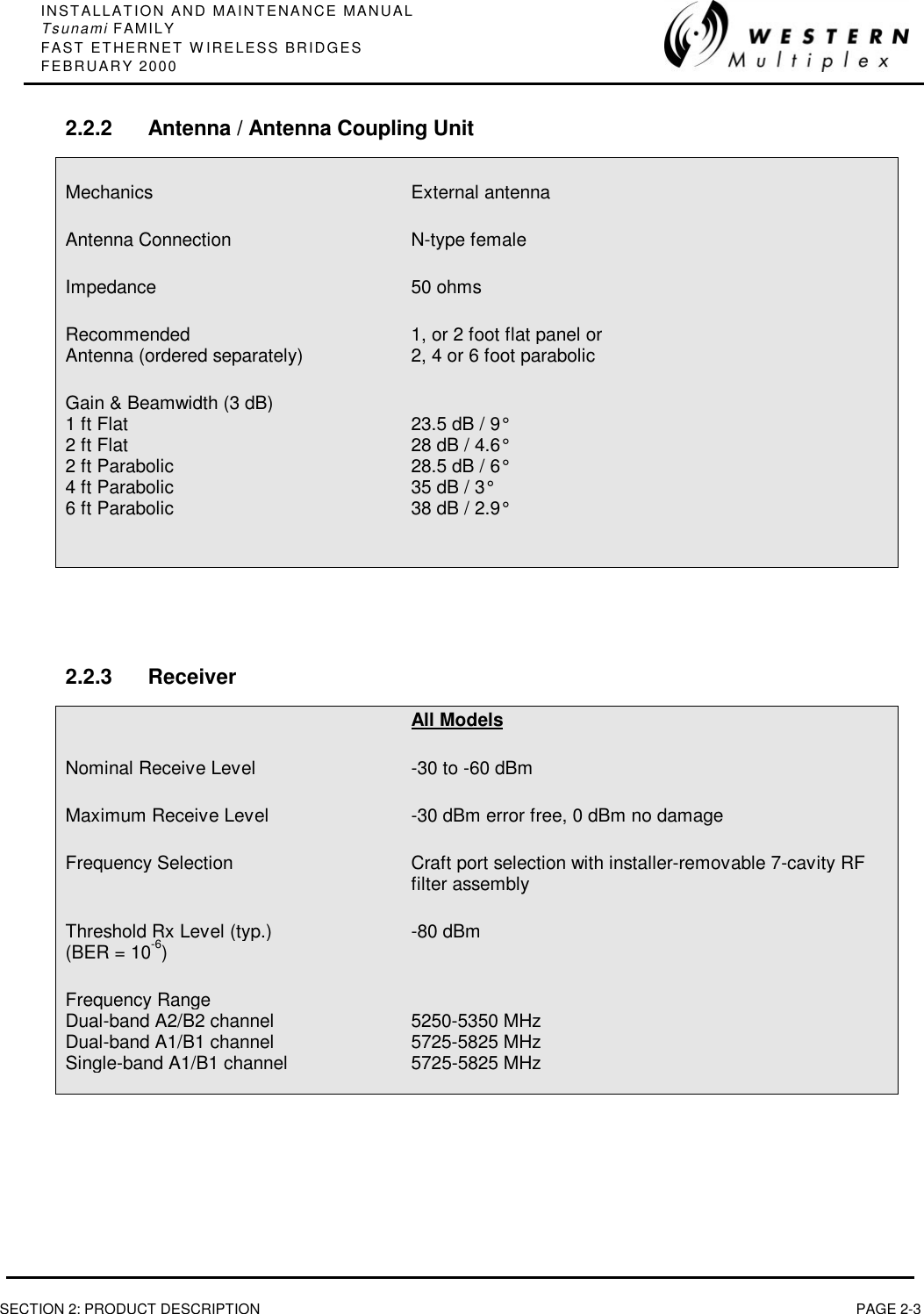

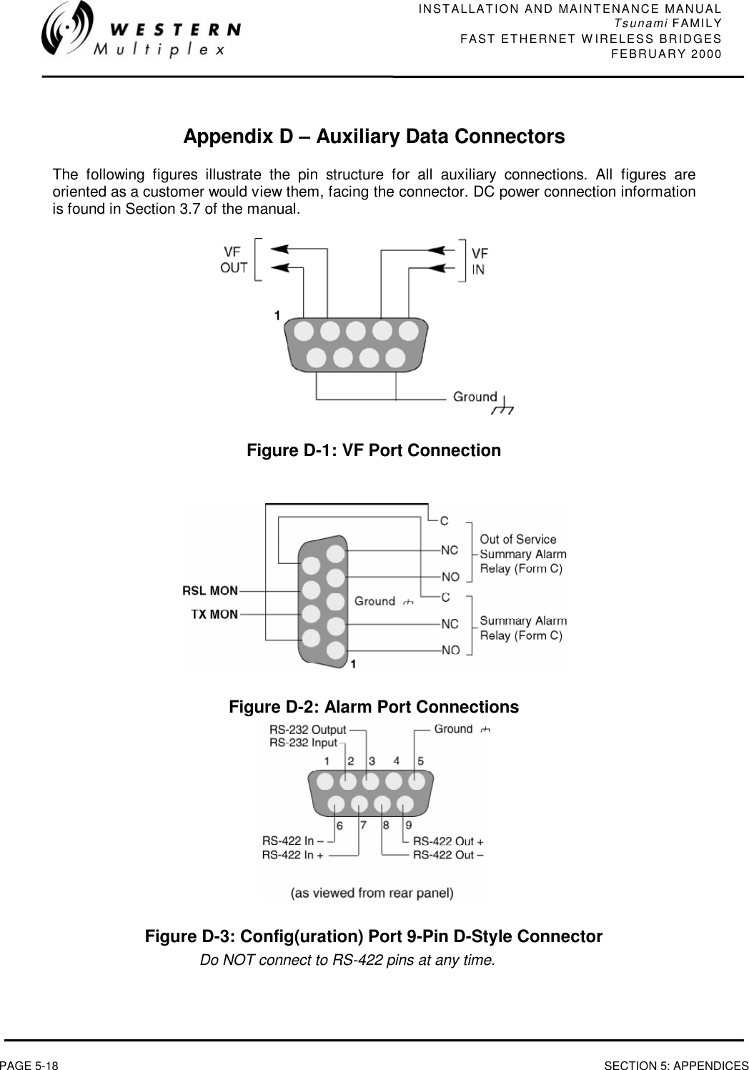
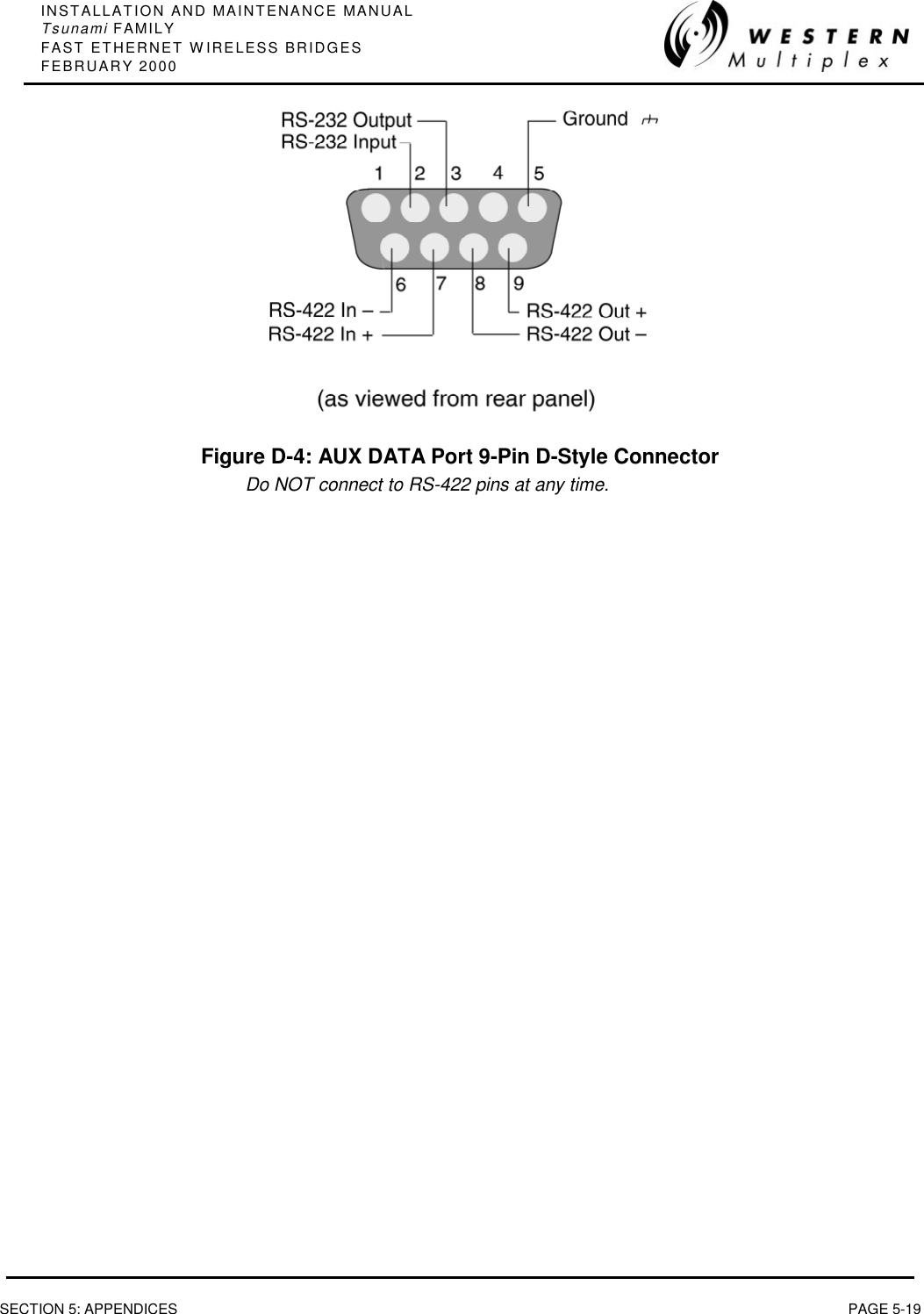
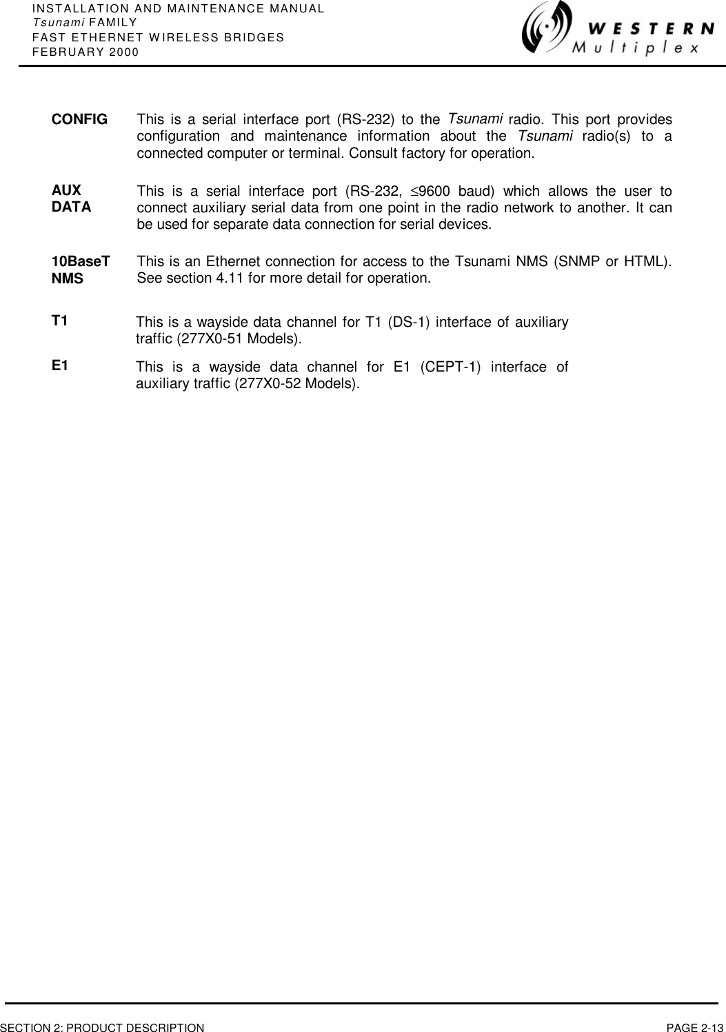
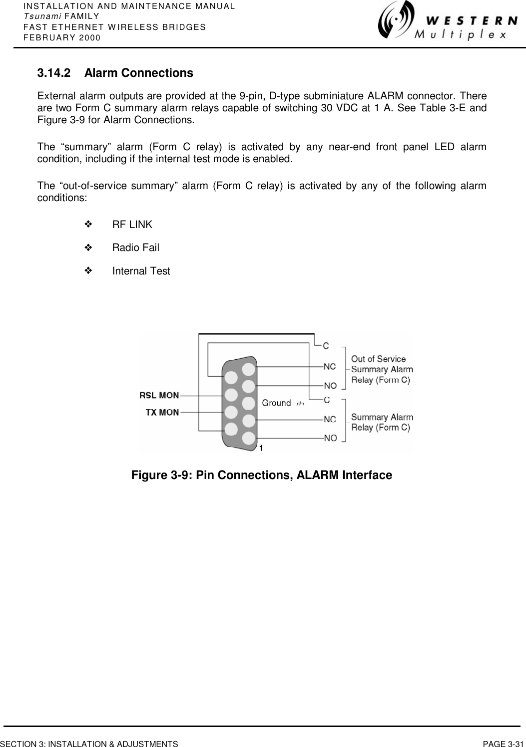
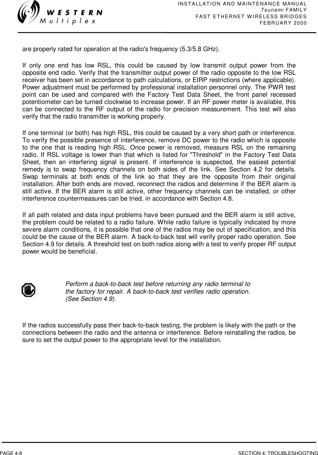
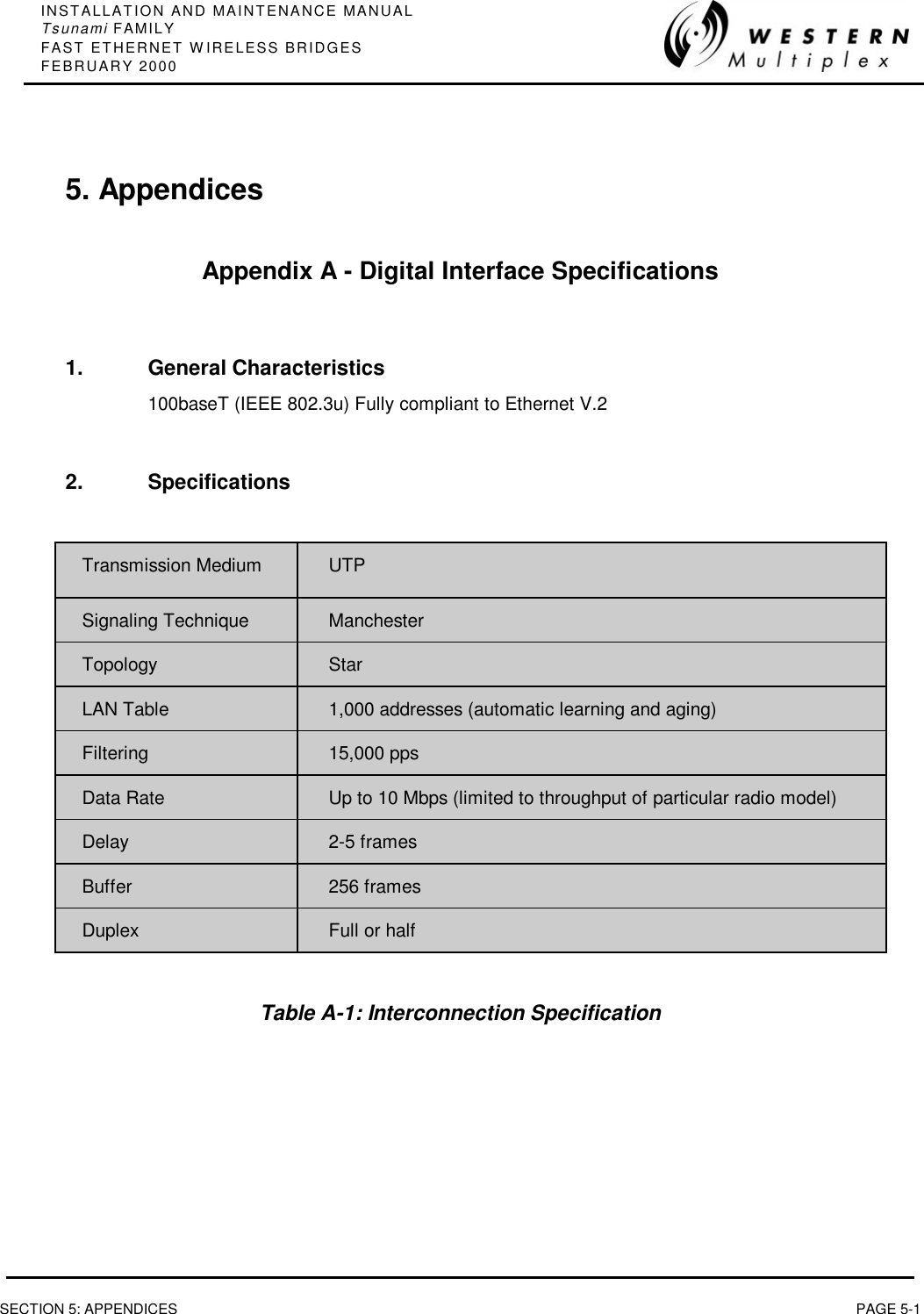
![INSTALLATION AND MAINTENANCE MANUALTsunami FAMILYFAST ETHERNET WIRELESS BRIDGES FEBRUARY 2000PAGE 2-12 SECTION 2: PRODUCT DESCRIPTION2.3.5 ConnectionsRF CONNECTIONThe RF port of the Tsunami radio is an N-type female connector that is an integral part of the filterassembly. The filter assembly occupies nearly the entire top half of the front panel. The N-Typeconnector is used to connect the antenna, typically using coaxial transmission line. In some cases,waveguide may be used as the primary transmission line, in which case a waveguide-to-N adapter isrequired.For the Tsunami, 1/2" or 5/8” coaxial cable (LDF4-50 or LDF4.5-50) is recommended. Coaxial cable that is 7/8” or larger can exhibitmoding at 5.8 GHz and is not recommended for 5.8 GHz radios.For waveguide transmission line at 5.8 GHz, EW-52 waveguide isrecommended. EW-63 will also work, but may exhibit more loss.DATA CONNECTIONThe connection for the Fast Ethernet interface that carries the signals in and out of the radio is anRJ45 100BaseT wire connection or ST 100BaseT fiber connection.DC POWER CONNECTIONThe input accepts positive or negative DC power at any voltage between 20 and 63 Volts. Optionally,an AC power adapter can be used.OPTIONAL CONNECTIONSThere are several connections that are not required for operation, but provide additional facilities tothe user.EOWVFThis connection is used to access the electronic orderwire function. This is a facilityfor "telephone" style service from one radio to another. A standard electronictelephone [one with a handset and DTMF (push-button tone) dialing] plugs into thisconnector. The user can dial the orderwire address of the far-end radio (or anyradio in the Tsunami network) to establish telephone communication between sites.This communication does not interrupt or interfere with the other radiocommunications. The radio link must be operational to use this facility. Theorderwire feature can be very useful for installation, maintenance andtroubleshooting.This connector is used to link two Tsunami radios at a repeater site for Orderwireoperation. This would allow orderwire "telephone" calls to and from any point in theTsunami network.The Tsunami orderwire circuit can also be connected to other existingorderwire networks. See Section 3.14.1 for details.ALARM This connector is used for monitoring alarms electrically. The Form C relays can beconnected to other transmission equipment for monitoring alarm status locally orremotely.](https://usermanual.wiki/Proxim-Wireless/U5358-100/User-Guide-102091-Page-28.png)
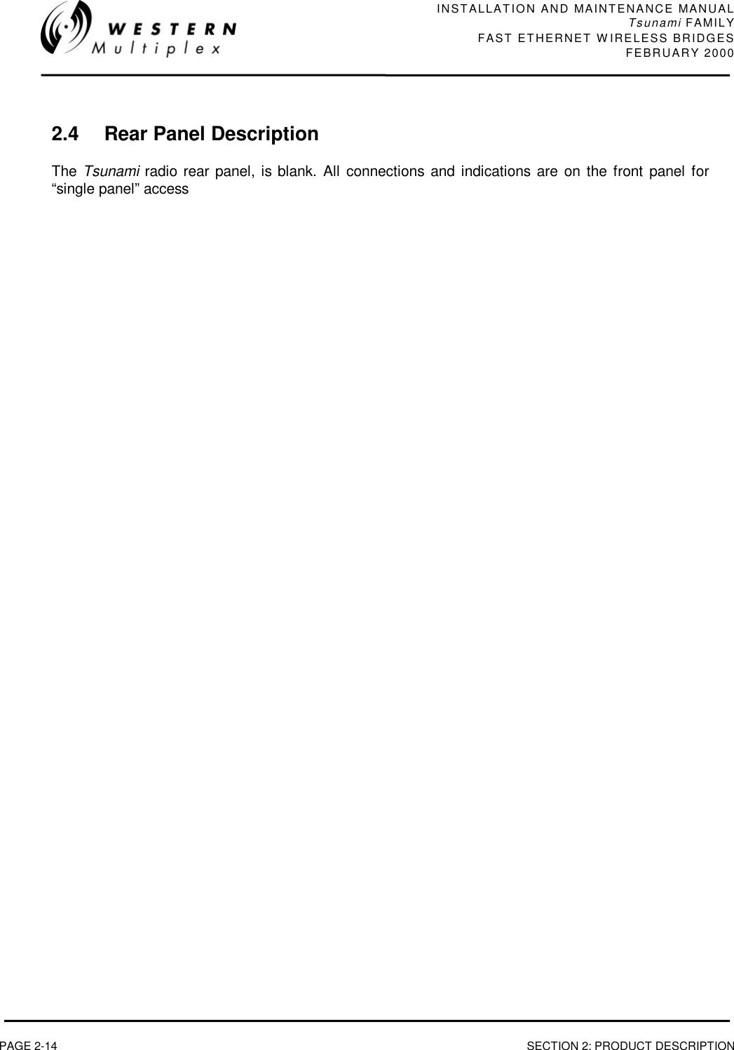


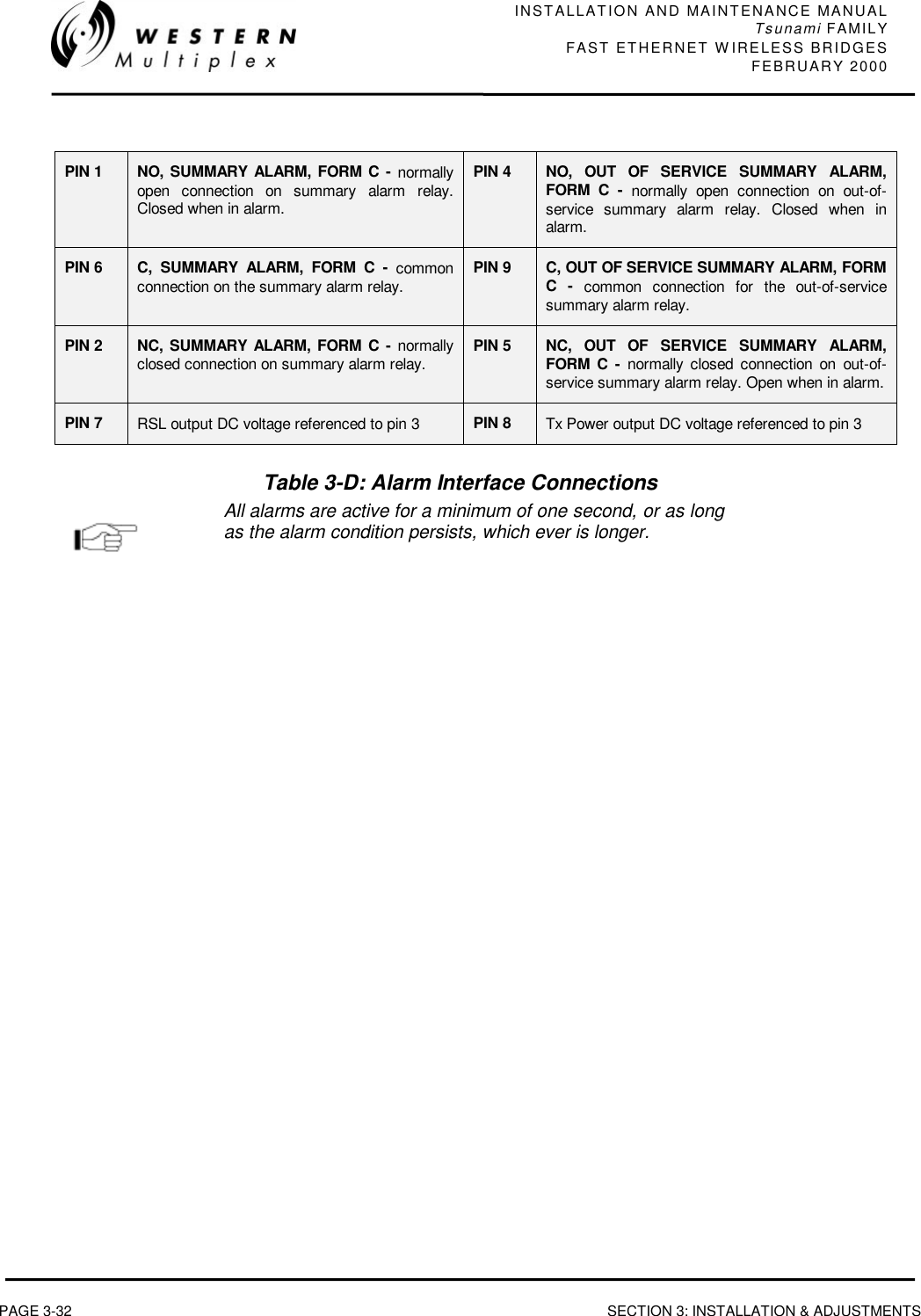

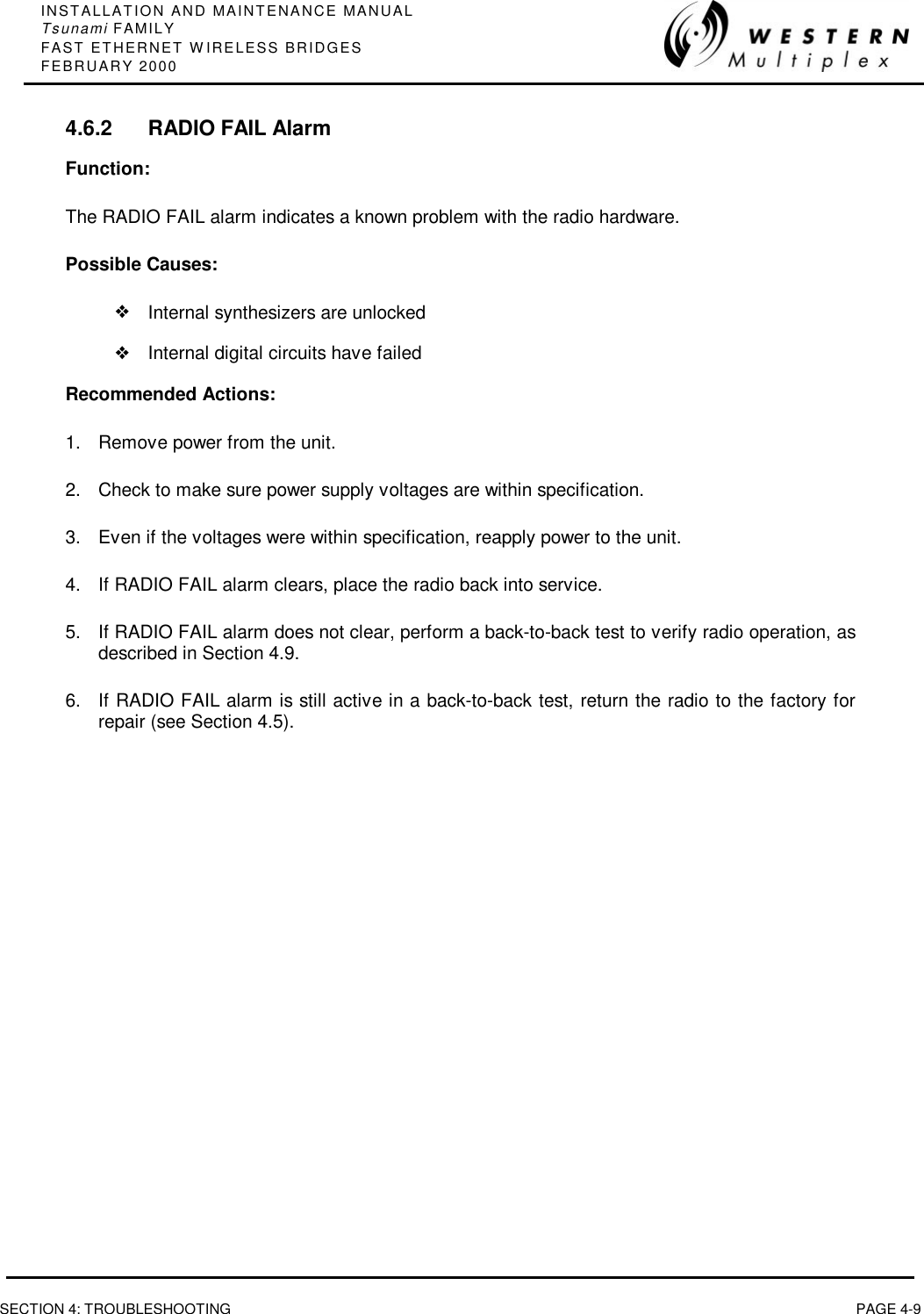


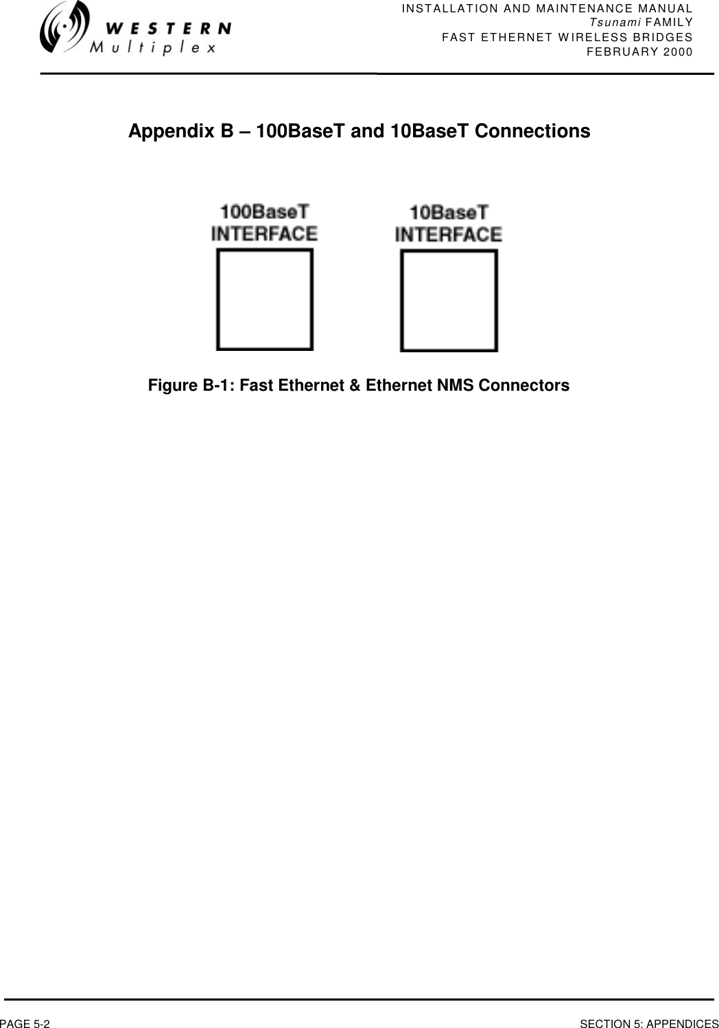
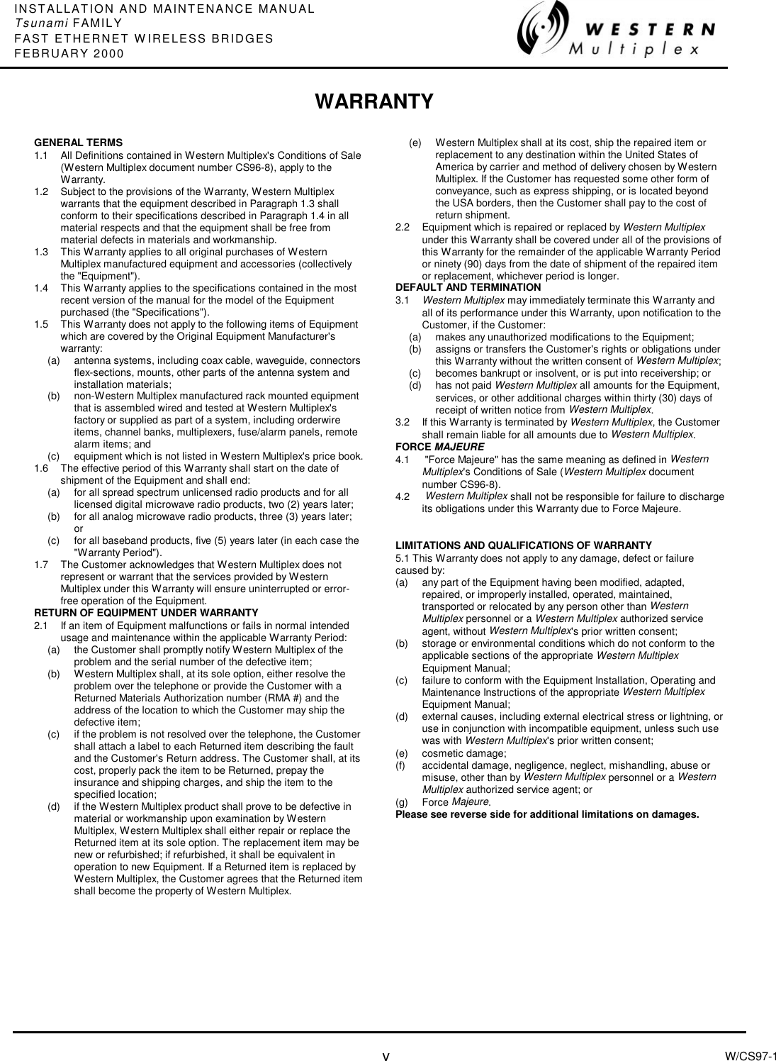
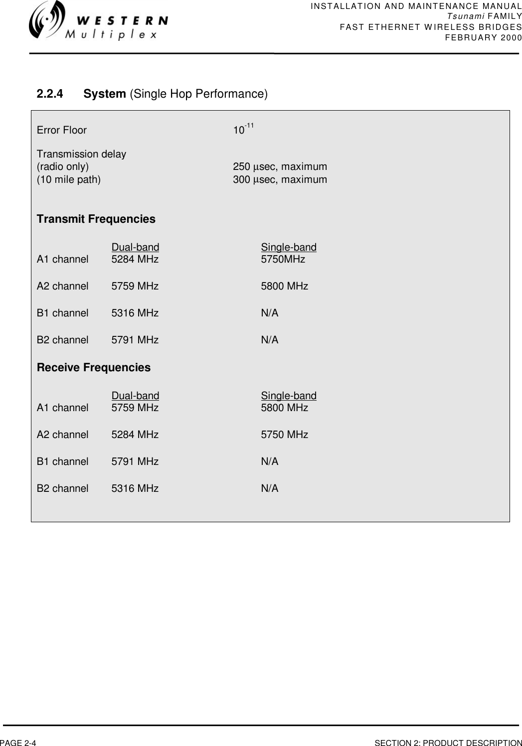
![INSTALLATION AND MAINTENANCE MANUALTsunami FAMILYFAST ETHERNET WIRELESS BRIDGESFEBRUARY 2000SECTION 5: APPENDICES PAGE 5-3Appendix C – Networking Q&AsQ: What is Ethernet?A: Ethernet is a type of network cabling and signaling specifications (OSI Model layers 1[physical] and 2 [data link]) originally developed by Xerox in the late 1970. The IEEE's(Institute of Electrical and Electronics Engineers) used Ethernet Version 2 as the basis forthe 802.3 CSMA/CD network standard.Q: What is an 802.3 network?A: That's IEEE-ish for Ethernet.Q: What is CSMA/CD?A: CSMA/CD is the media access control mechanism used by Ethernet and 802.3 networks;in other words, it determines how a packet of data is placed on the wire. CSMA/CDstands for "Carrier Sense Multiple Access, with Collision Detection". Before an Ethernetdevice puts a packet "on the wire", it listens to find if another device is alreadytransmitting. Once the device finds the wire is clear, it starts sending the packet whilealso listening to hear if another device started sending at the same time (which is calleda collision). Refer to the Q&A on collisions for more info about this phenomena.Q: What is an OSI Model?A: The Open Systems Interconnect (OSI) reference model is the ISO (InternationalStandards Organization) structure for the "ideal" network architecture. This Modeloutlines seven areas, or layers, for the network. These layers are (from highest tolowest): LAYER7) Applications: Where the user applications software lies. Such issues as file accessand transfer (FTP), virtual terminal emulation, Internet connections (HTTP), inter-process communication and the like are handled here.6) Presentation: Differences in data representation are dealt with at this level. Forexample, UNIX-style line endings (CR only) might be converted to MS-DOS style(CRLF), or EBCIDIC to ASCII character sets.5) Session: Communications between applications across a net- work is controlled atthe session layer. Testing for out-of-sequence packets and handling two-waycommunication are handled here.4) Transport: Makes sure the lower three layers are doing their job correctly, andprovides a transparent, logical data stream between the end user and the networkservice s/he is using. This is the lower layer that provides local user services.3) Network: This layer makes certain that a packet sent from one device to anotheractually gets there in a reasonable period of time. Routing and flow control areperformed here. This is the lowest layer of the OSI model that can remain ignorant](https://usermanual.wiki/Proxim-Wireless/U5358-100/User-Guide-102091-Page-101.png)
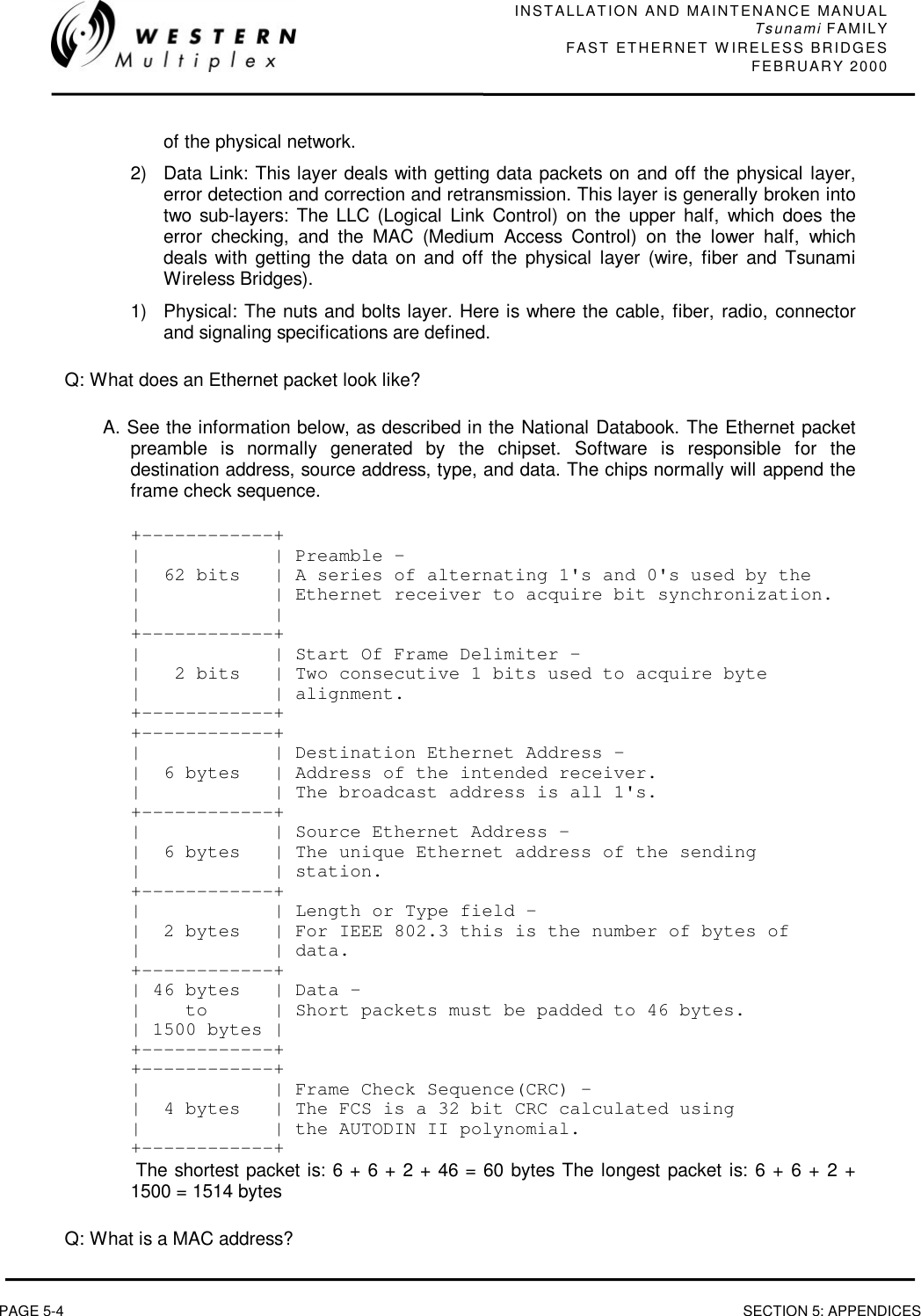
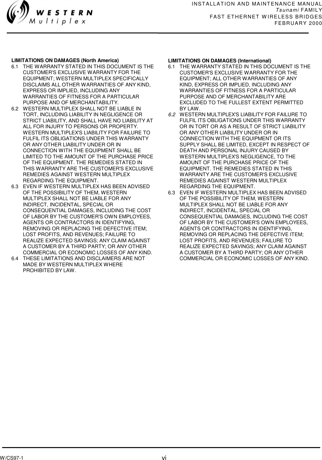
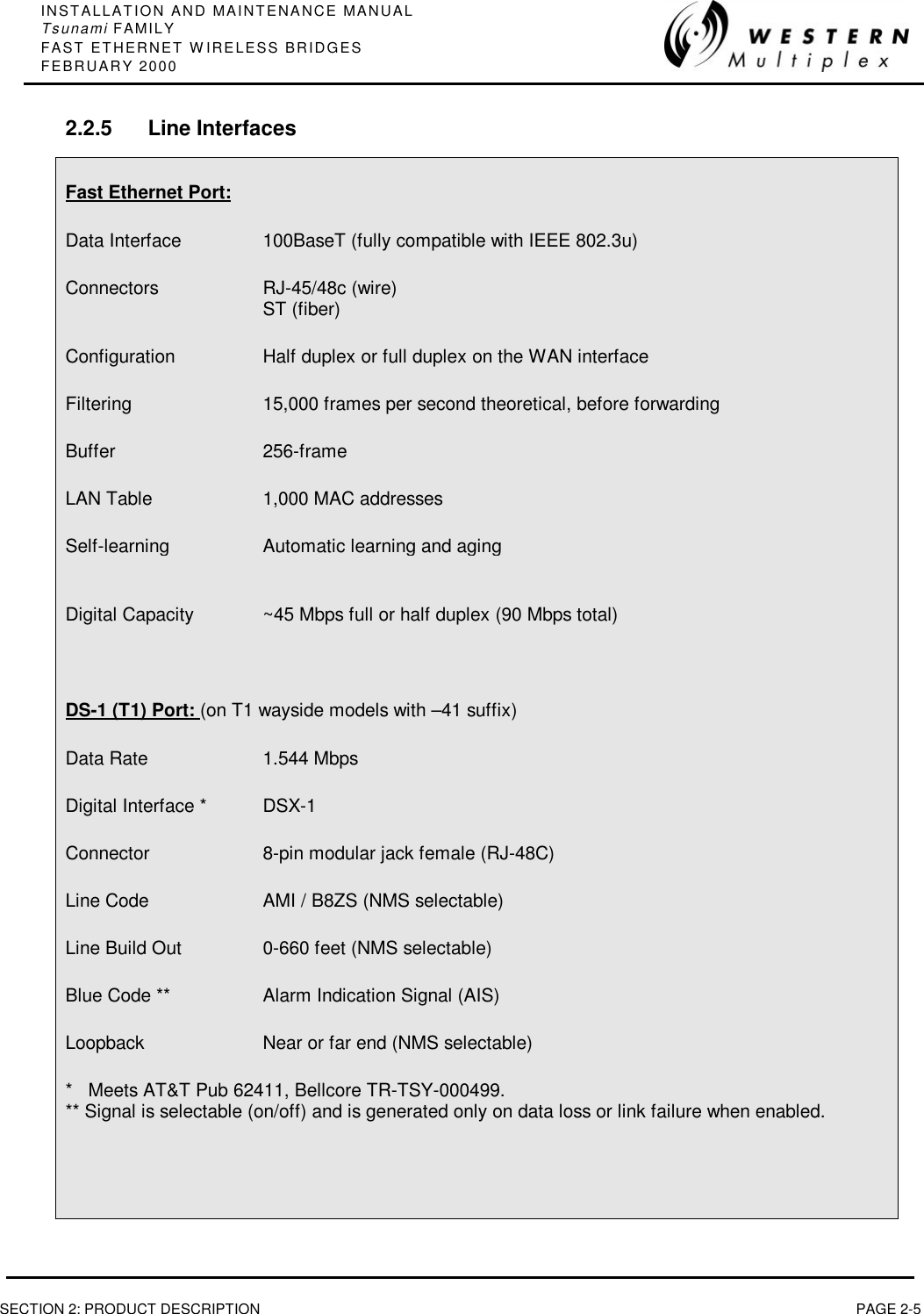
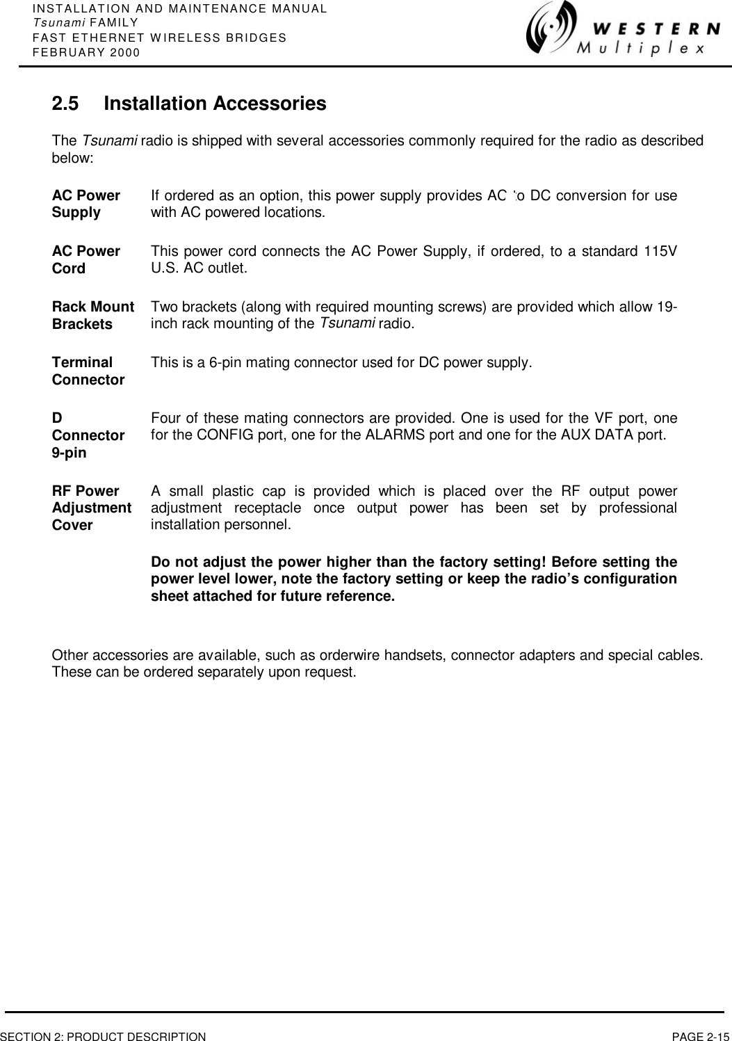
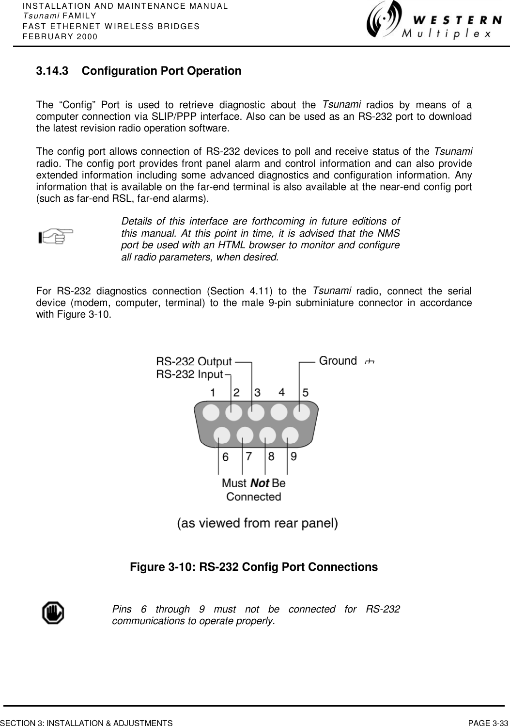
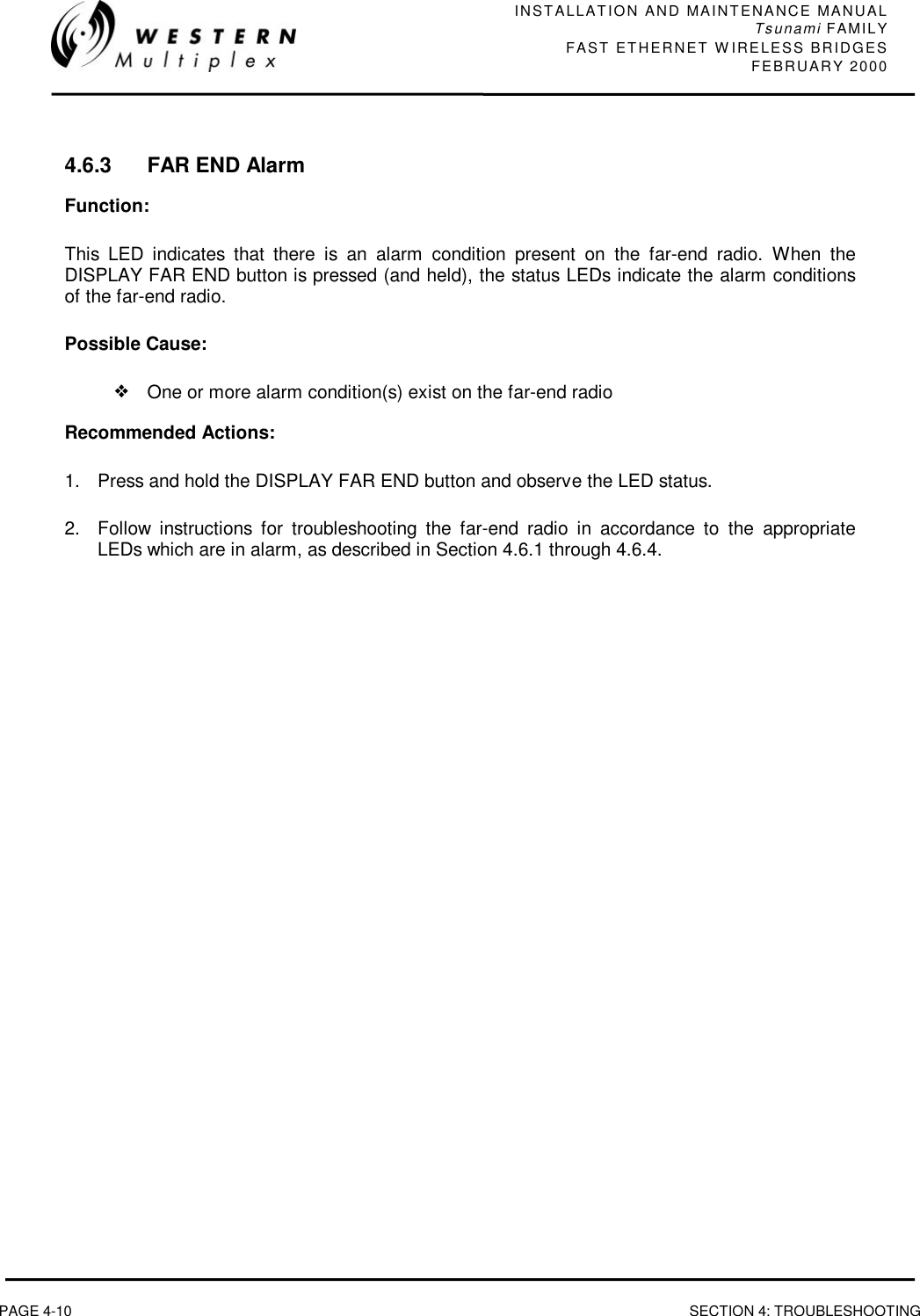
![INSTALLATION AND MAINTENANCE MANUALTsunami FAMILYFAST ETHERNET WIRELESS BRIDGESFEBRUARY 2000SECTION 5: APPENDICES PAGE 5-7Q: Is there an official "standard" punch down scheme for 10BaseT?A: Get a copy of EIA/TIA-568, it covers all of that sort of stuff: horizontal, vertical,connectors, patch cords, cross-connects, etc.Q: Is it safe to run Unshield Twisted Pair next to power cable?A: According to EIA/TIA-569, the standard wiring practices for running data cabling andcompanion to the above referenced EIA/TIA-568, you should not run data cable parallelto power cables. However, in reality, this should not be a problem with networks such as10BaseT. 10BaseT uses differential signaling to pick the data signals off the wire. Sinceany interference from nearby power lines will usually affect all pairs equally, anythingthat is not canceled-out by the twists in the UTP should be ignored by the receivingnetwork interface.Q: Can I connect the 10BaseT interface of two devices directly together, without using a hub?A: Yes, but not more than 2 devices, and you also need a special jumper cable between thetwo 10BaseT ports: RJ45 pin RJ45 pin ======== ========1 <--[TX+]--------[RX+]--> 32 <--[TX-]--------[RX-]--> 63 <--[RX+]--------[TX+]--> 16 <--[RX-]--------[TX-]--> 2Q: What is a "segment"?A: A piece of network wire bounded by bridges, routers, repeaters or terminators.Q: What is a "subnet"?A: Another overloaded term. It can mean, depending on the usage, a segment, a set ofmachines grouped together by a specific protocol feature (note that these machines donot have to be on the same segment, but they could be) or a big nylon thing used tocapture enemy subs.Q: What is a repeater?A: A repeater acts on a purely electrical level to connect to segments. All it does is amplifyand reshape (and, depending on the type, possibly retime) the analog waveform toextend network segment distances. It does not know anything about addresses orforwarding, thus it cannot be used to reduce traffic as a bridge can in the exampleabove.Q: What is a "hub"?A: A hub is a common wiring point for star-topology networks, and is a common synonymfor concentrator (though the latter generally has additional features or capabilities).](https://usermanual.wiki/Proxim-Wireless/U5358-100/User-Guide-102091-Page-105.png)
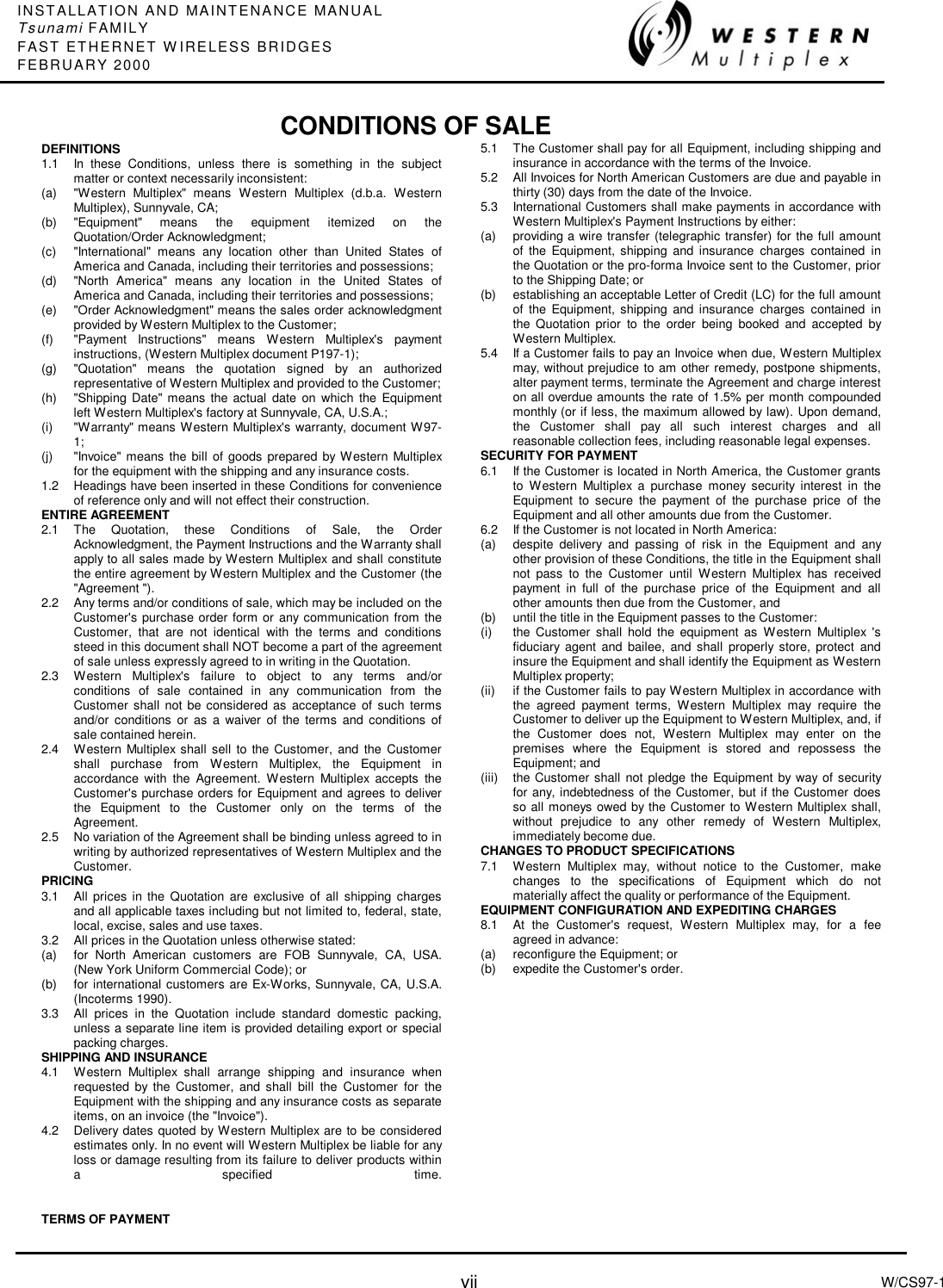
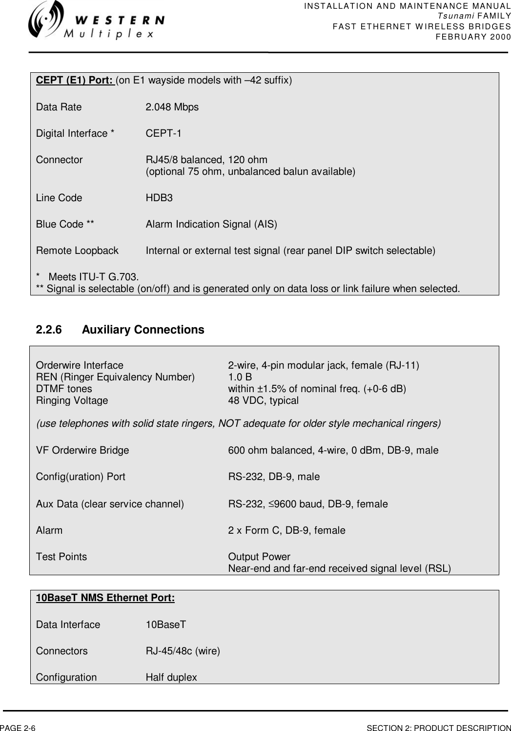
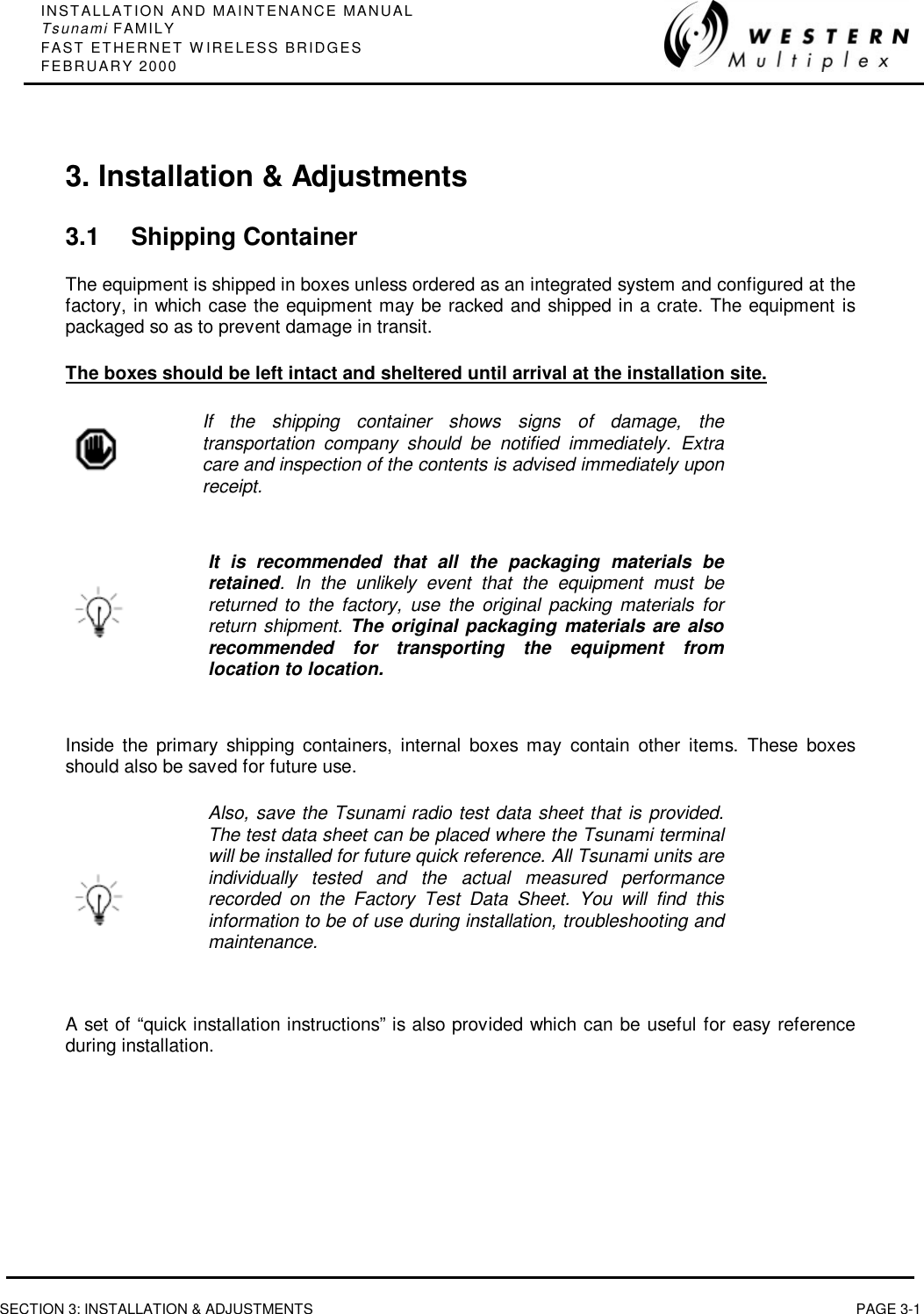
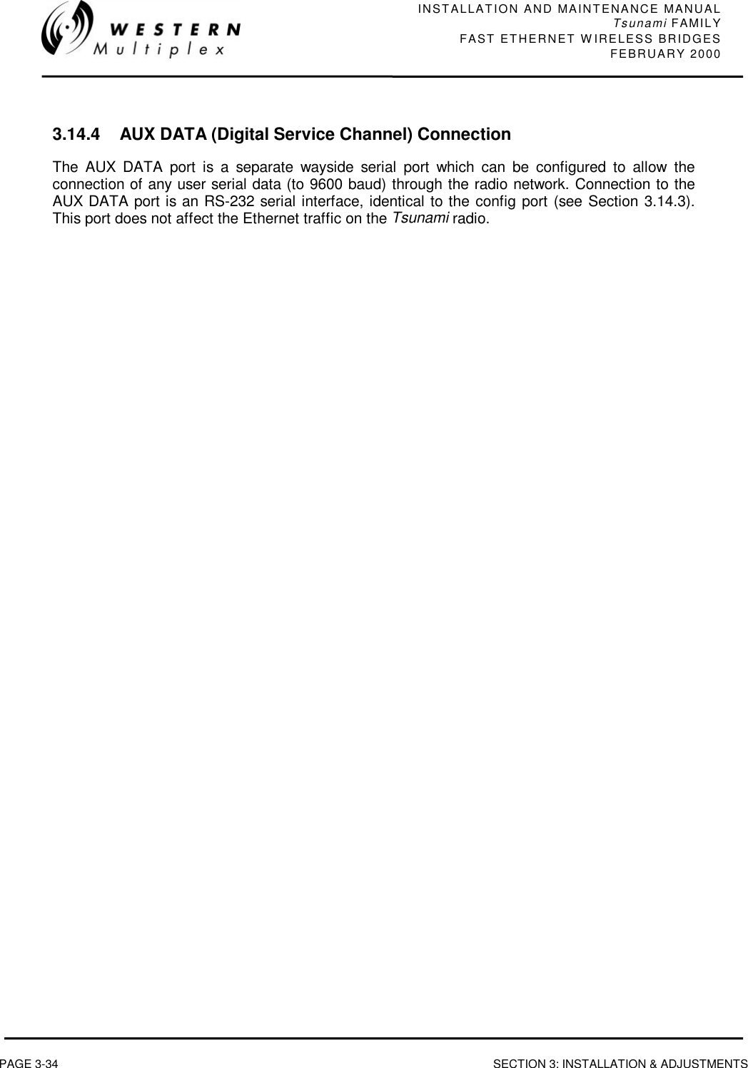
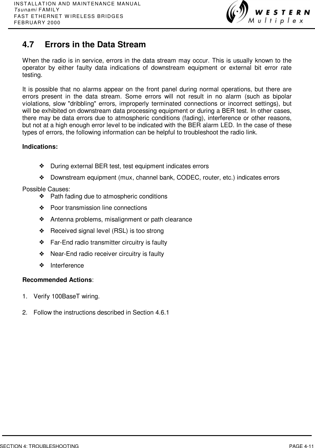
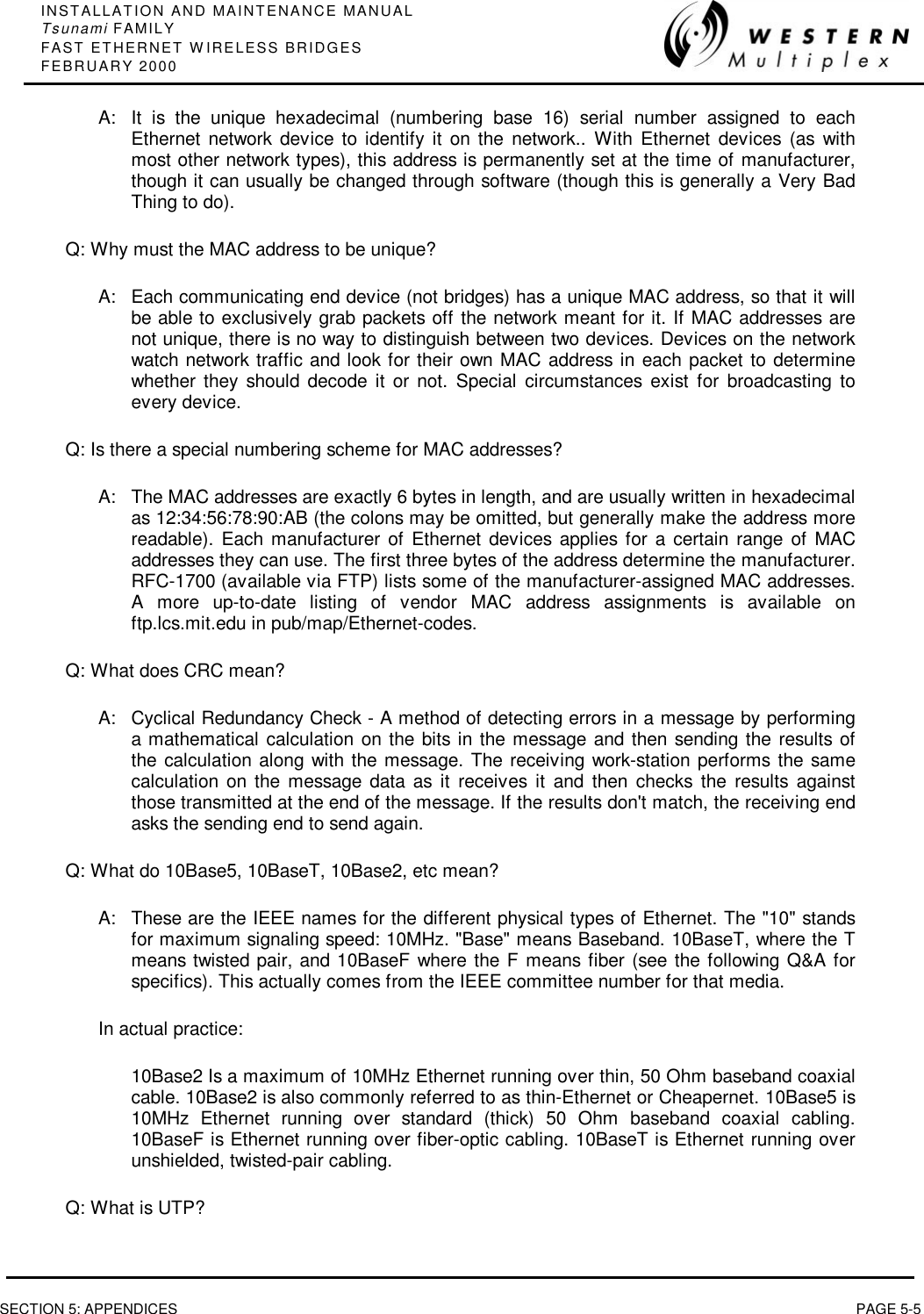
![INSTALLATION AND MAINTENANCE MANUALTsunami FAMILYFAST ETHERNET WIRELESS BRIDGESFEBRUARY 2000SECTION 5: APPENDICES PAGE 5-13DOS commands (through Windows DOS application) are:ARPDisplays and modifies the IP-to-Physical address translation tables used by addressresolution protocol (ARP). ARP -a [inet_addr] [-N if_addr] -a Displays current ARP entries by interrogating the current protocol data. Ifinet_addr is specified, the IP and Physical addresses for only the specifiedcomputer are displayed. If more than one network interface uses ARP, entriesfor each ARP table are displayed. -g Same as -a.inet_addr Specifies an internet address.-N if_addr Displays the ARP entries for the network interface specified by if_addr. -d Deletes the host specified by inet_addr. -s Adds the host and associates the Internet address inet_addr with the Physicaladdress eth_addr. The Physical address is given as 6 hexadecimal bytesseparated by hyphens. The entry is permanent.eth_addr Specifies a physical address.if_addr If present, this specifies the Internet address of the interface whoseaddress translation table should be modified. If not present, the firstapplicable interface will be used. Example: > arp -s 157.55.85.212 00-aa-00-62-c6-09 .... Adds a static entry. > arp -a .... Displays the arp table.FTPTransfers files to and from a computer running an FTP server service (sometimes calleda daemon). FTP can be used interactively.FTP [-v] [-d] [-i] [-n] [-g] [-s:filename] [-a] [-w:windowsize] [-A] [host]-v Suppresses display of remote server responses.-n Suppresses auto-login upon initial connection.-i Turns off interactive prompting during multiple file transfers.-d Enables debugging.-g Disables filename globbing (see GLOB command).-s:filename Specifies a text file containing FTP commands; the commands willautomatically run after FTP starts.-a Use any local interface when binding data connection.-A login as anonymous.-w:buffersize Overrides the default transfer buffer size of 4096.host Specifies the host name or IP address of the remote host to connect to.Notes: - mget and mput commands take y/n/q for yes/no/quit. - Use Control-C to abort commands.NET CONFIG Displays your current workgroup settings.NET DIAG Runs the Microsoft Network Diagnostics program to display](https://usermanual.wiki/Proxim-Wireless/U5358-100/User-Guide-102091-Page-111.png)
![INSTALLATION AND MAINTENANCE MANUALTsunami FAMILYFAST ETHERNET WIRELESS BRIDGES FEBRUARY 2000PAGE 5-14 SECTION 5: APPENDICESdiagnostic information about your network.NET HELP Provides information about commands and error messages.NET INIT Loads protocol and network-adapter drivers without bindingthem to Protocol Manager.NET LOGOFF Breaks the connection between your computer and the sharedresources to which it is connected.NET LOGON Identifies you as a member of a workgroup.NET PASSWORD Changes your logon password.NET PRINT Displays information about print queues and controls print jobs.NET START Starts services.NET STOP Stops services.NET TIME Displays the time on or synchronizes your computer's clock withthe clock on a Microsoft Windows for Workgroups, Windows NT,Windows 95, or NetWare time server.NET USE Connects to or disconnects from a shared resource or displaysinformation about connections.NET VER Displays the type and version number of the workgroupredirector you are using.NET VIEW Displays a list of computers that share resources or a list ofshared resources on a specific computer.For more information about a specific Microsoft NET command, type the commandname followed by /? (for example, NET VIEW /?).PINGPING [-t] [-a] [-n count] [-l size] [-f] [-i TTL] [-v TOS] [-r count] [-s count] [[-j host-list] | [-k host-list]] [-w timeout] destination-list-t Ping the specified host until stopped. To see statistics and continue -type Control-Break; To stop - type Control-C.-a Resolve addresses to hostnames.-n count Number of echo requests to send.-l size Send buffer size.-f Set Don't Fragment flag in packet.-i TTL Time To Live.-v TOS Type Of Service.-r count Record route for count hops.-s count Timestamp for count hops.-j host-list Loose source route along host-list.-k host-list Strict source route along host-list.](https://usermanual.wiki/Proxim-Wireless/U5358-100/User-Guide-102091-Page-112.png)
![INSTALLATION AND MAINTENANCE MANUALTsunami FAMILYFAST ETHERNET WIRELESS BRIDGESFEBRUARY 2000SECTION 5: APPENDICES PAGE 5-15-w timeout Timeout in milliseconds to wait for each reply.ROUTEManipulates network routing tables.ROUTE [-f] [command [destination] [MASK netmask] [gateway] [METRIC metric]]-f Clears the routing tables of all gateway entries. If this is used in conjunction withone of the commands, the tables are cleared prior to running the command.command Must be one of four:PRINT Prints a routeADD Adds a routeDELETE Deletes a routeCHANGE Modifies an existing routedestination Specifies the destination host.MASK Specifies that the next parameter is the 'netmask' value.netmask Specifies a subnet mask value to be associated with this route entry. Ifnot specified, it defaults to 255.255.255.255.gateway Specifies gateway.METRIC Specifies that the next paramenter 'metric' is the cost for this destinationAll symbolic names used for destination are looked up in the network database fileNETWORKS. The symbolic names for gateway are looked up in the host namedatabase file HOSTS.If the command is PRINT or DELETE, wildcards may be used for the destination andgateway, or the gateway argument may be omitted.Diagnostic Notes:Invalid MASK generates an error, that is when (DEST & MASK) != DEST.Example> route ADD 157.0.0.0 MASK 155.0.0.0 157.55.80.1The route addition failed: 87Examples:> route PRINT> route ADD 157.0.0.0 MASK 255.0.0.0 157.55.80.1 METRIC 3^destination ^mask ^gateway ^metric> route PRINT> route DELETE 157.0.0.0> route PRINTSNMPStarts SNMP agent-close Closes previously running instance of snmp](https://usermanual.wiki/Proxim-Wireless/U5358-100/User-Guide-102091-Page-113.png)
![INSTALLATION AND MAINTENANCE MANUALTsunami FAMILYFAST ETHERNET WIRELESS BRIDGES FEBRUARY 2000PAGE 5-16 SECTION 5: APPENDICES-help Displays SNMP help dialog boxTELNETOpens telnet windowTRACERTTRACERT [-d] [-h maximum_hops] [-j host-list] [-w timeout] target_name-d Do not resolve addresses to hostnames.-h maximum_hops Maximum number of hops to search for target.-j host-list Loose source route along host-list.-w timeout Wait timeout milliseconds for each reply.WINIPCFGOpens IP configuration window/All - Display detailed information/Batch - [filename] Write to file or .\winipcfg.out/renew_all - Renew all adapters/release_all - Release all adapters/renew N - Renew adapter N/release N - Release adapter NQ: What books are good about Ethernet LAN's?A: The IEEE 802.3 documents are considered the definitive source for information onEthernet. However, these may not be suitable for all levels of users. Surprisingly, thereare few good books specifically dealing with Ethernet LANs, but here are a few that youmight find useful:Local Area Networks, An introduction to the technology by John E. McNamara, publishedby Digital Press, 1985 165 pps. with index and glossary, $29.00 ISBN 0-932376-79-7,Digital Press part number EY-00051-DP.Network Troubleshooting Guide by Digital Equipment Corporation, August 1990 Approx.278 pps. with index and glossary, $95.00 Digital Press part number EK-339AB-GD-002.These books and others are recommended in the network reading list, net-read.txt, fromftp.utexas.edu.Q: Where can I get IEEE802.x docs online?A: Not available online. IEEE documents can be ordered directly from the IEEEthemselves. You can contact them at:Institute of Electrical and Electronic Engineers 445 Hoes Lane P.O. Box 1331Piscataway, NJ 08855-1331 U.S.A. (800) 678-IEEE](https://usermanual.wiki/Proxim-Wireless/U5358-100/User-Guide-102091-Page-114.png)