Proxim Wireless US5358-GX1 Unlicensed NII Transceiver User Manual Backing down from TNG CCI 2
Proxim Wireless Corporation Unlicensed NII Transceiver Backing down from TNG CCI 2
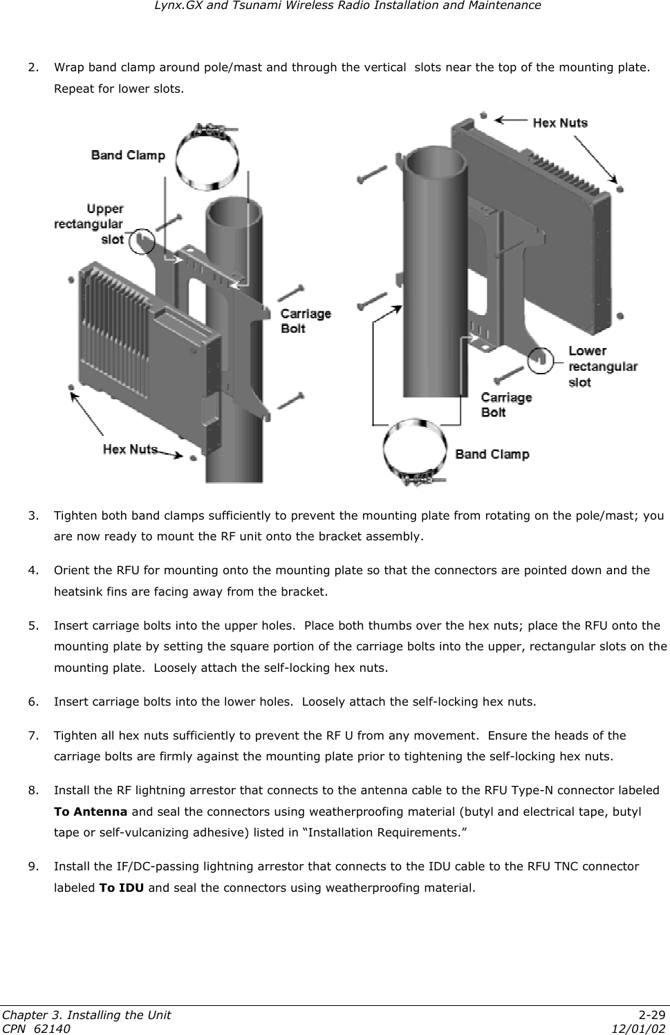
UserManual.wiki
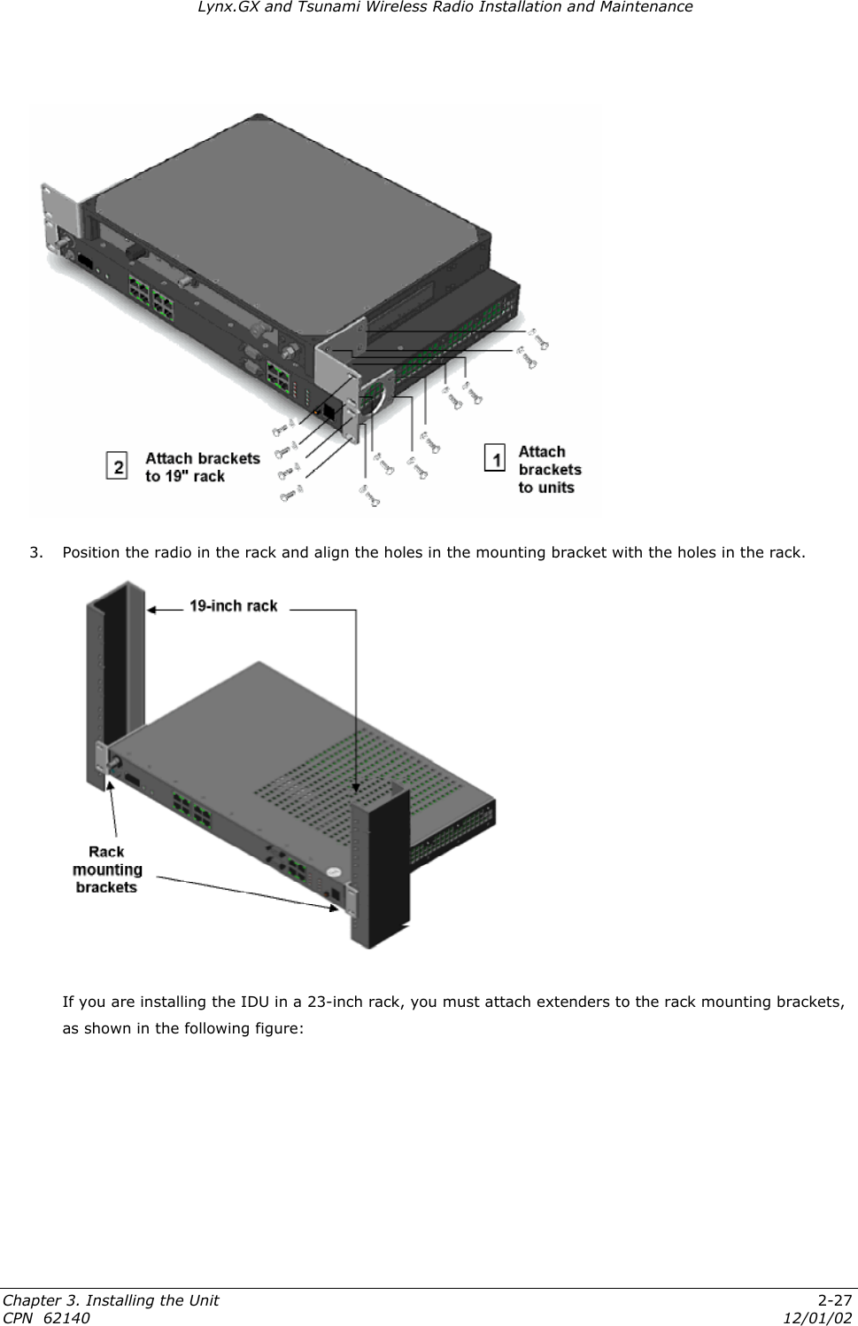
>
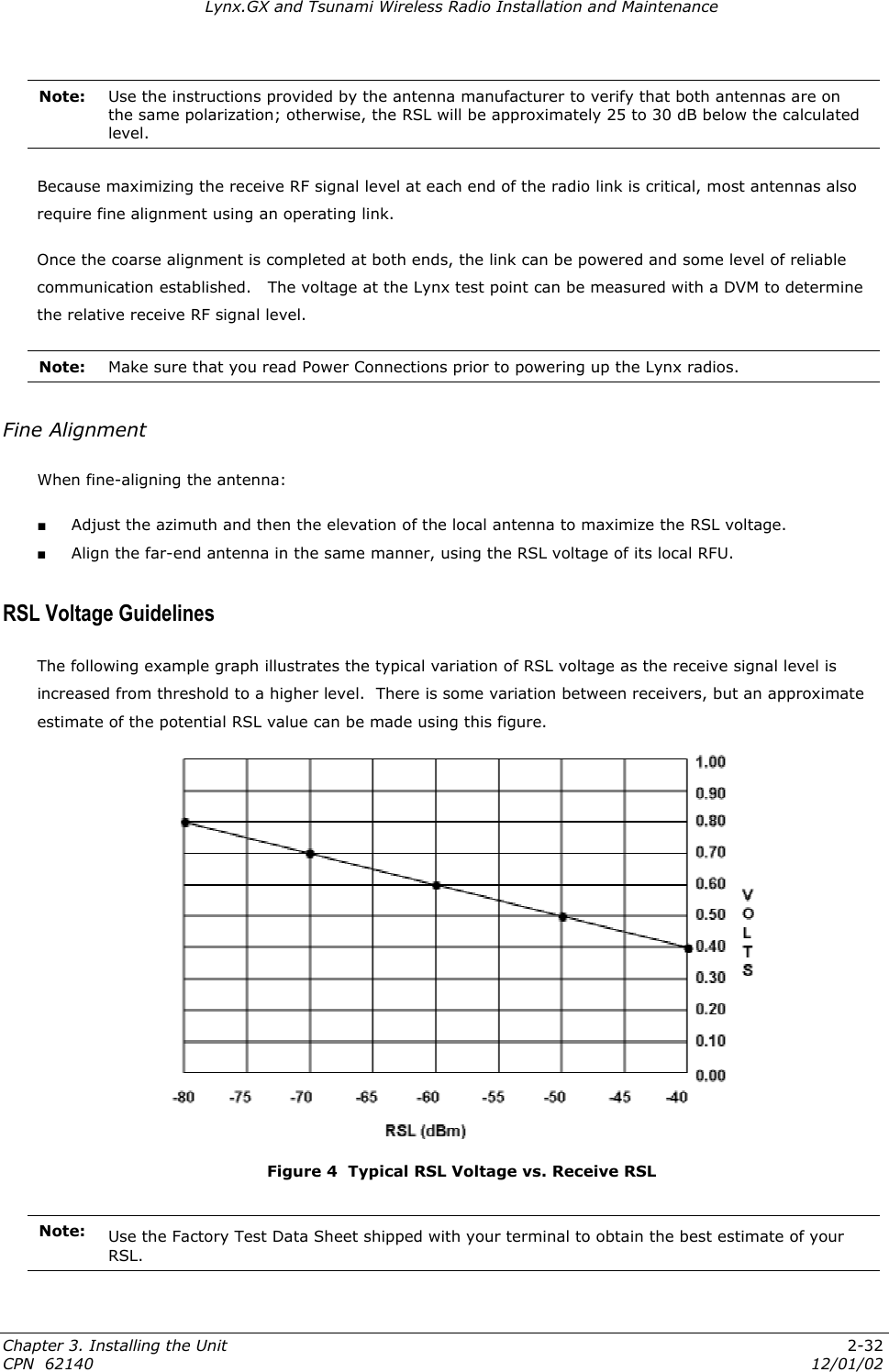
Proxim Wireless
>
US5358 GX1 User Manual
Installation Manual
Navigation menu
Upload a User Manual
Namespaces
Wiki Guide
HTML
PDF
Info
Views
User Manual
Discussion / Help
Navigation


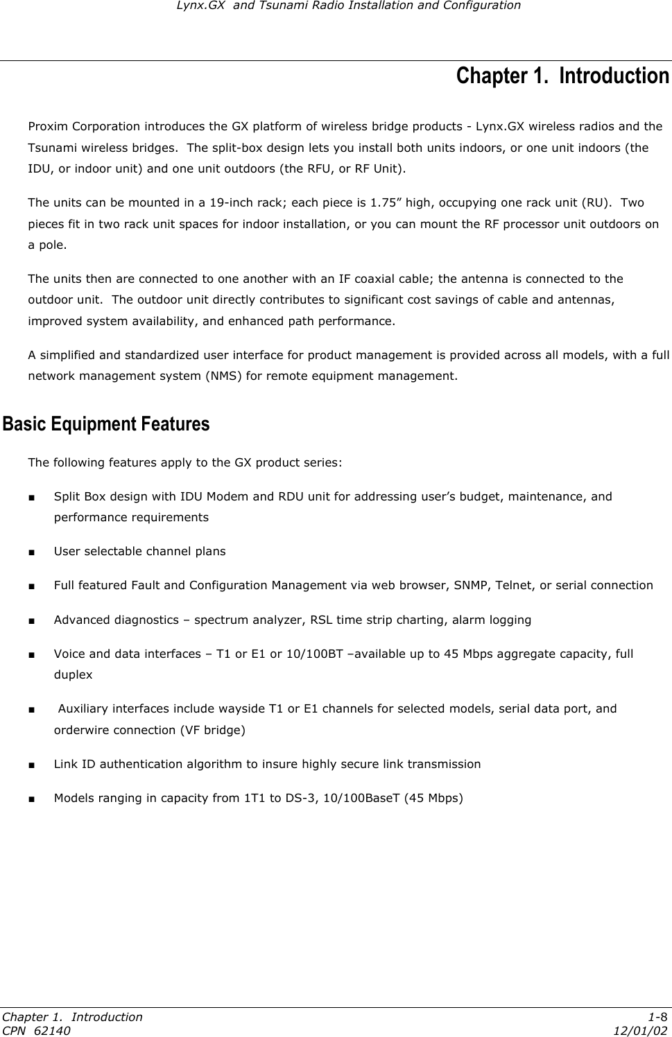
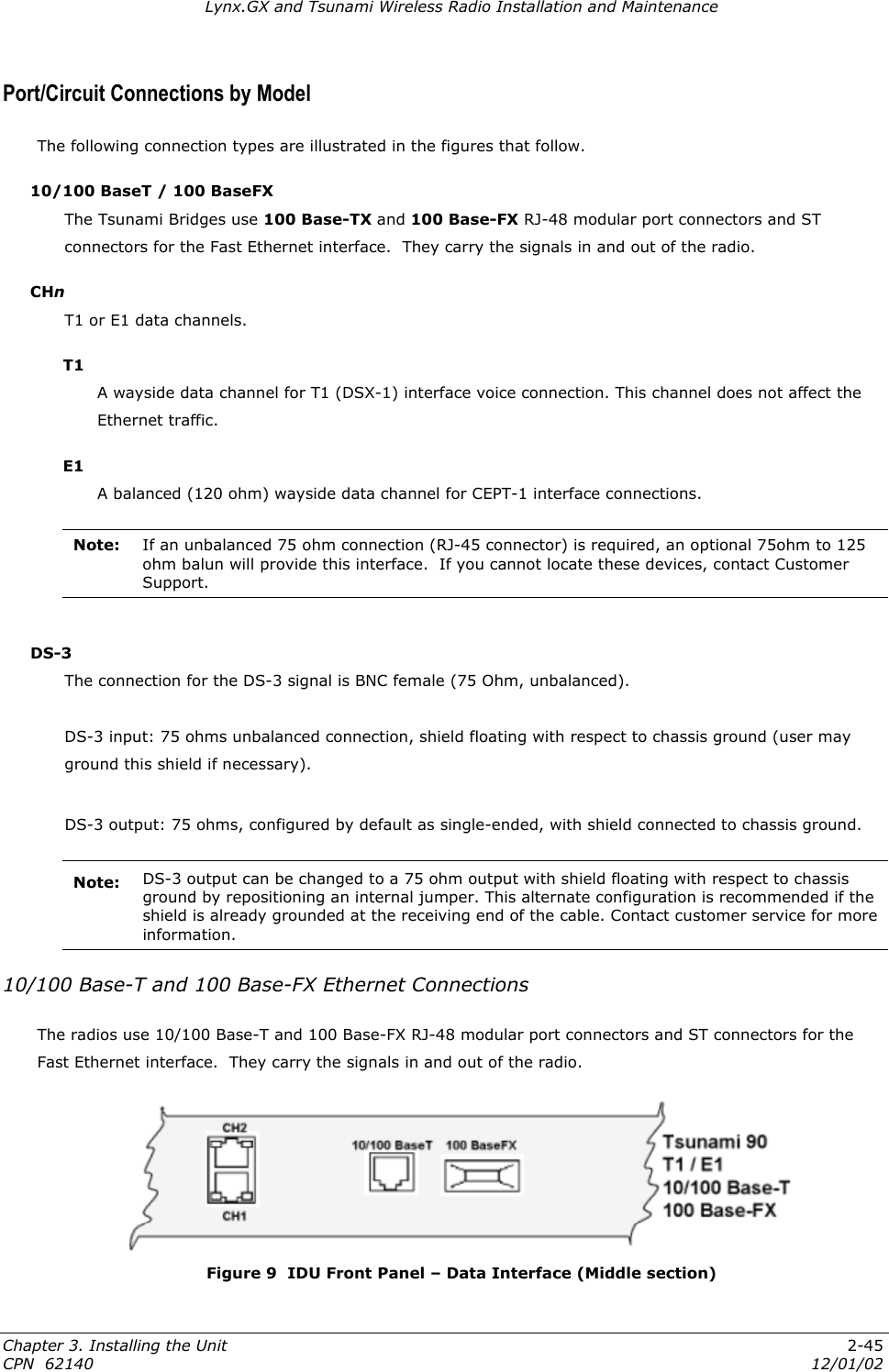
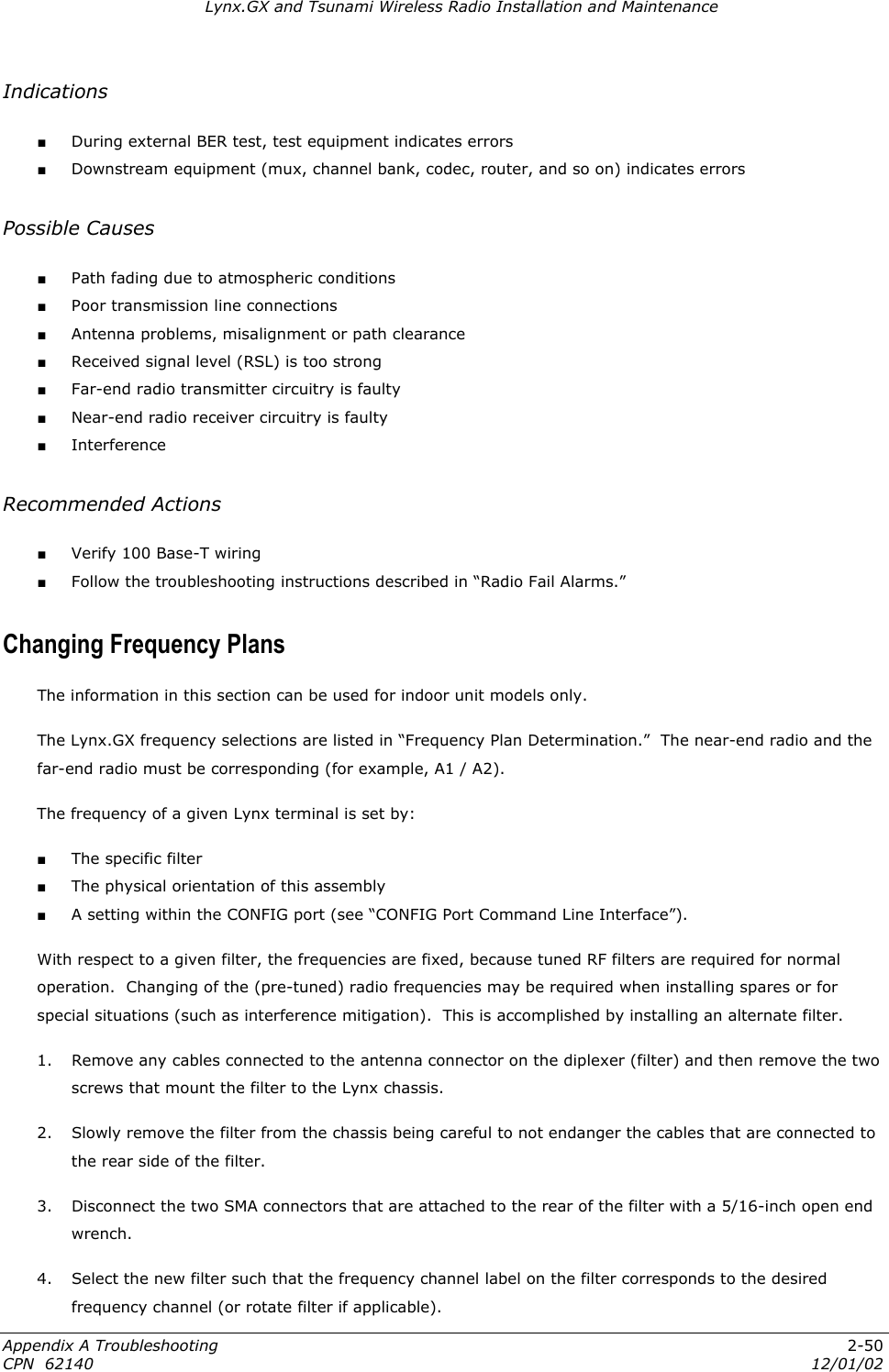
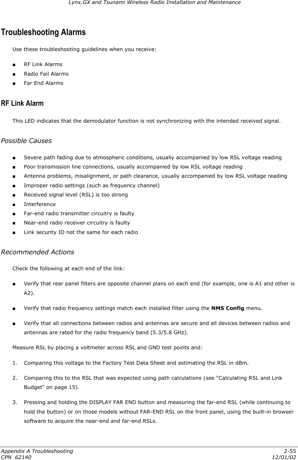
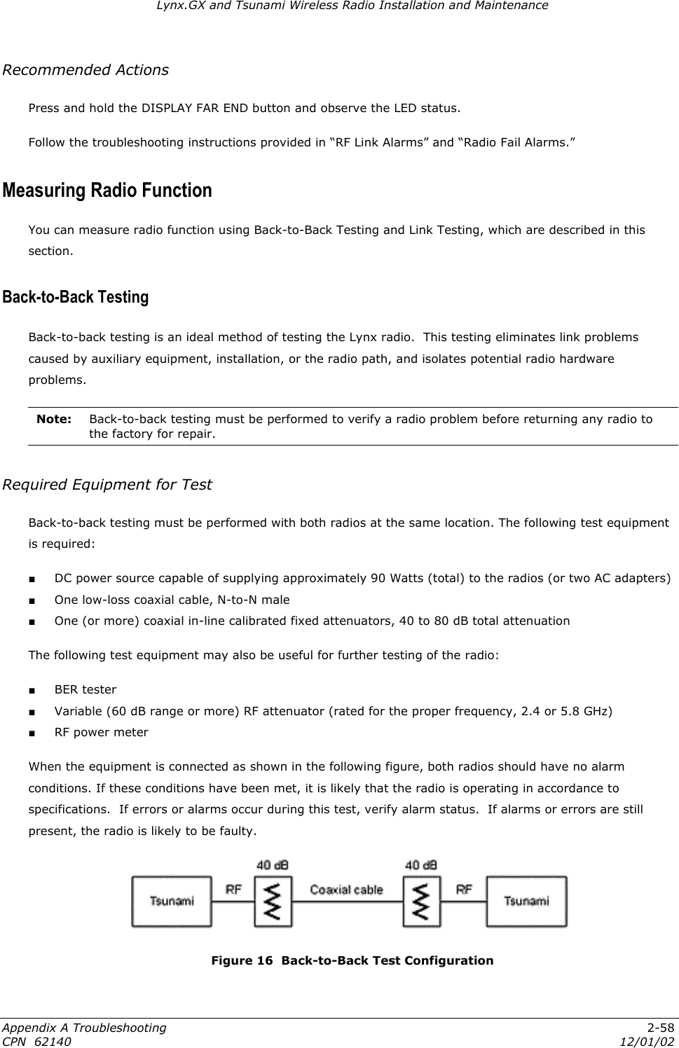
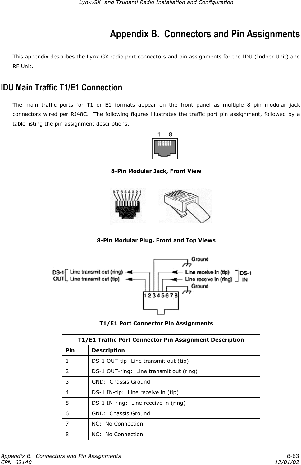
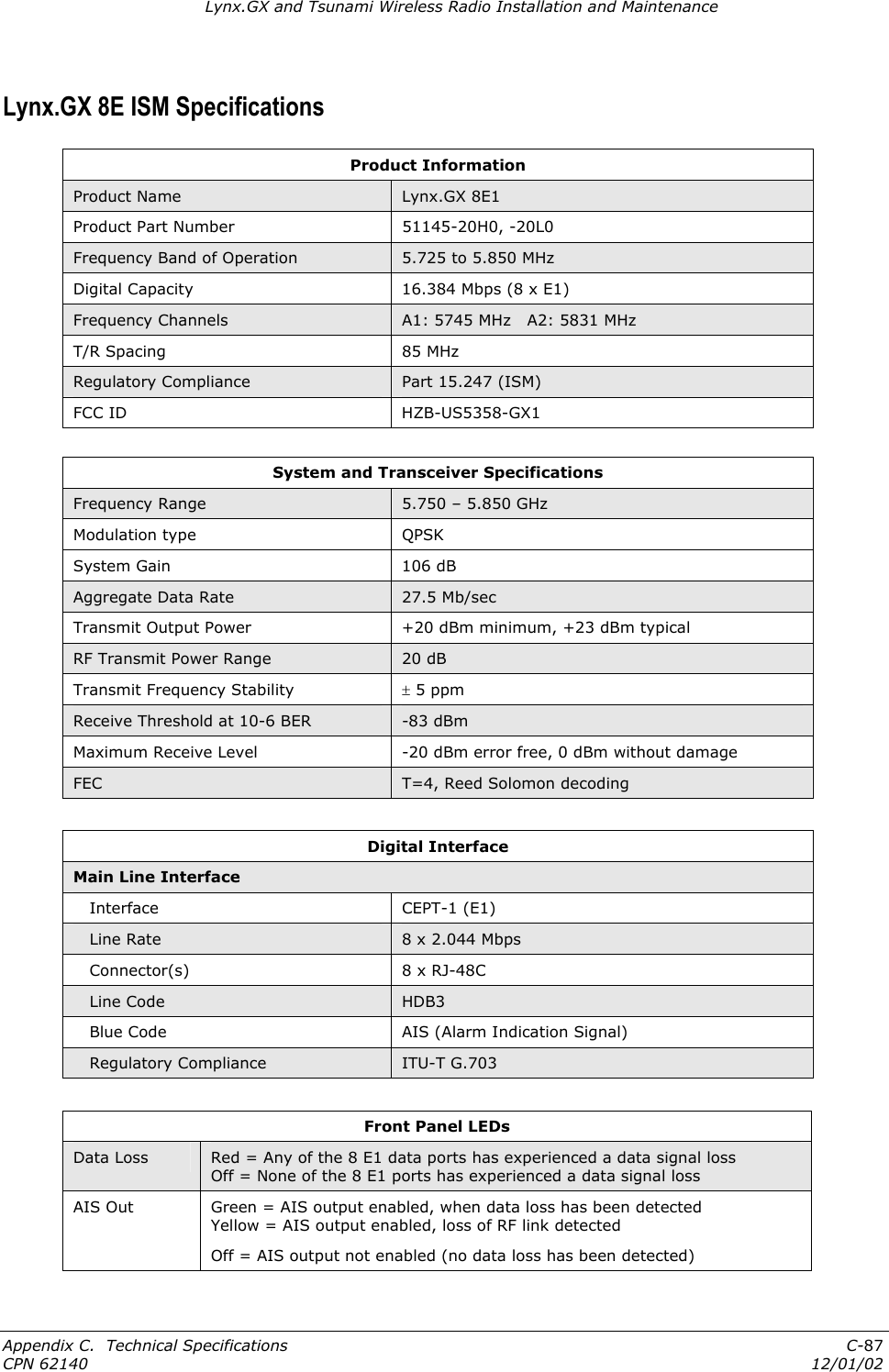
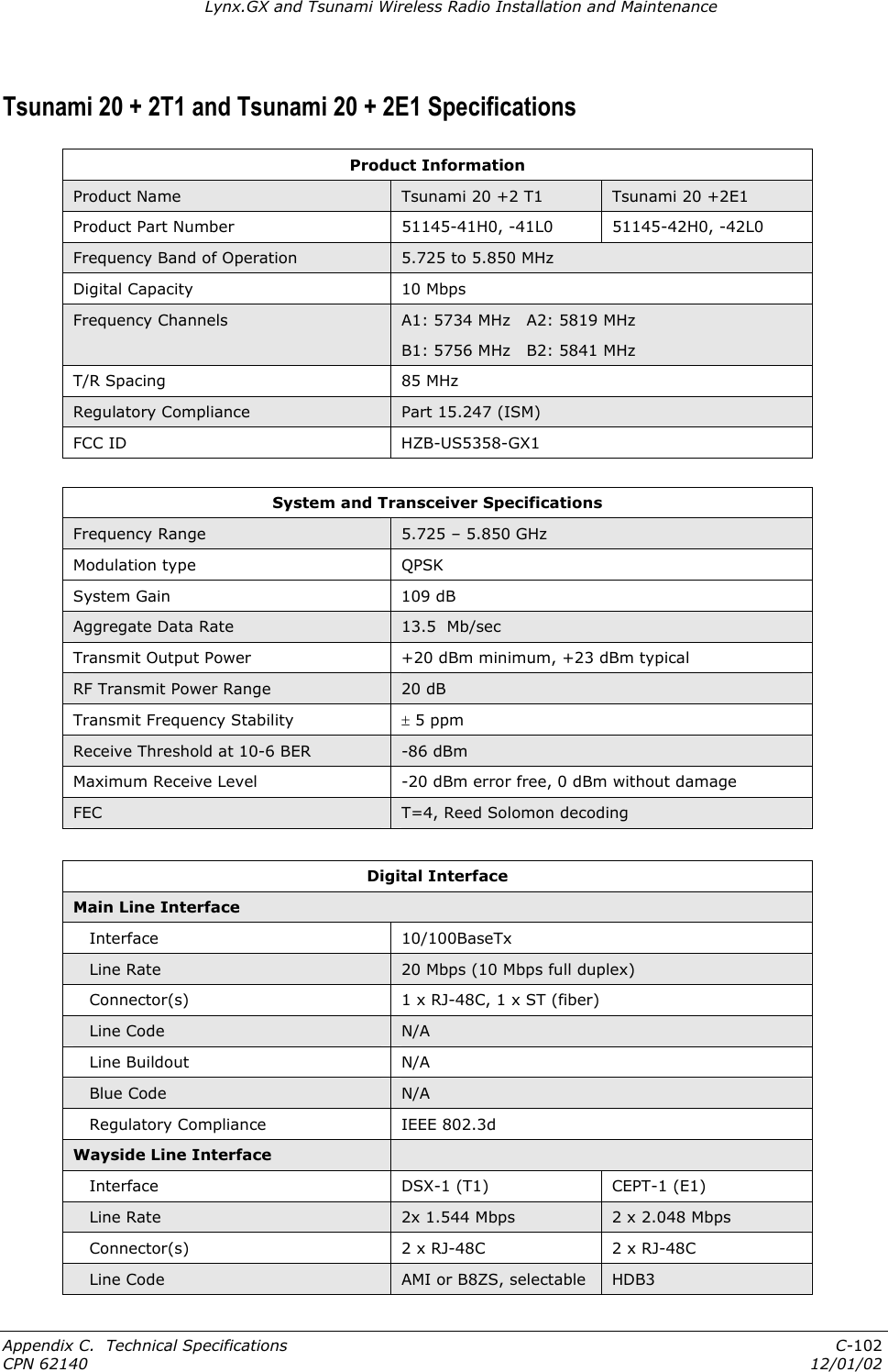
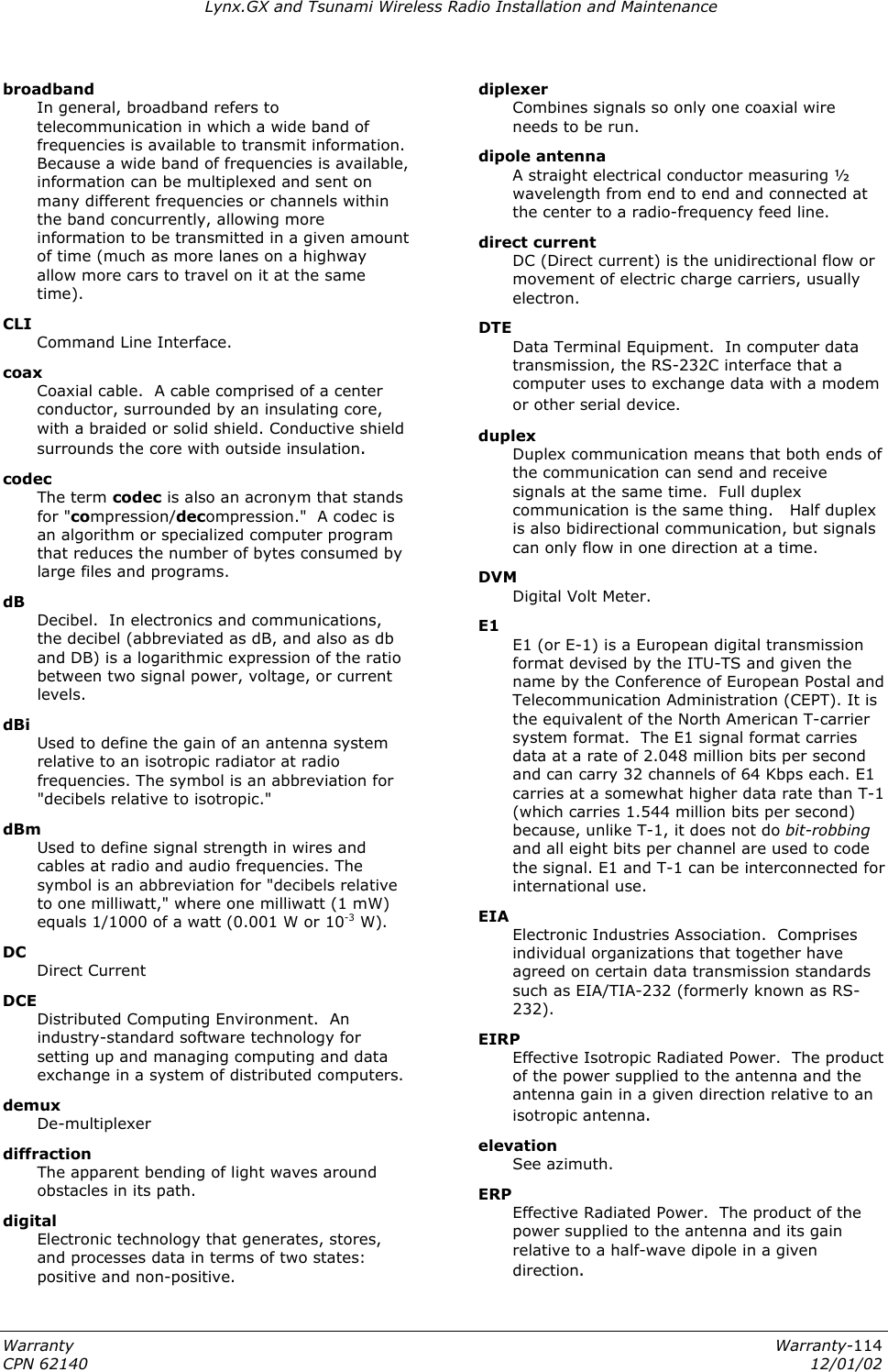
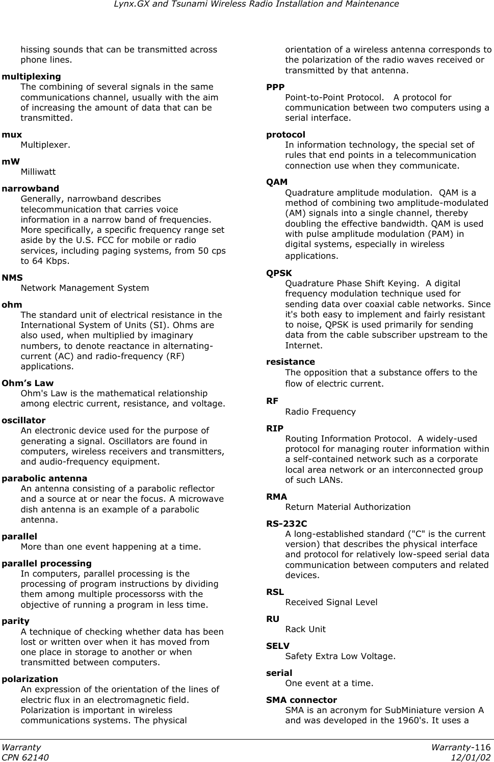
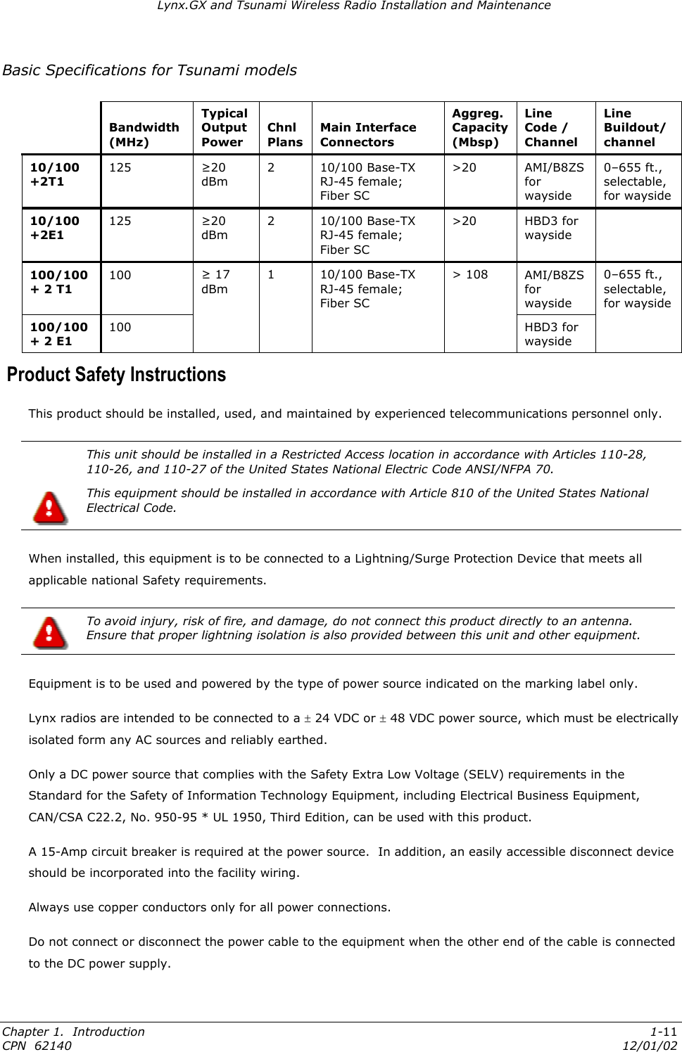
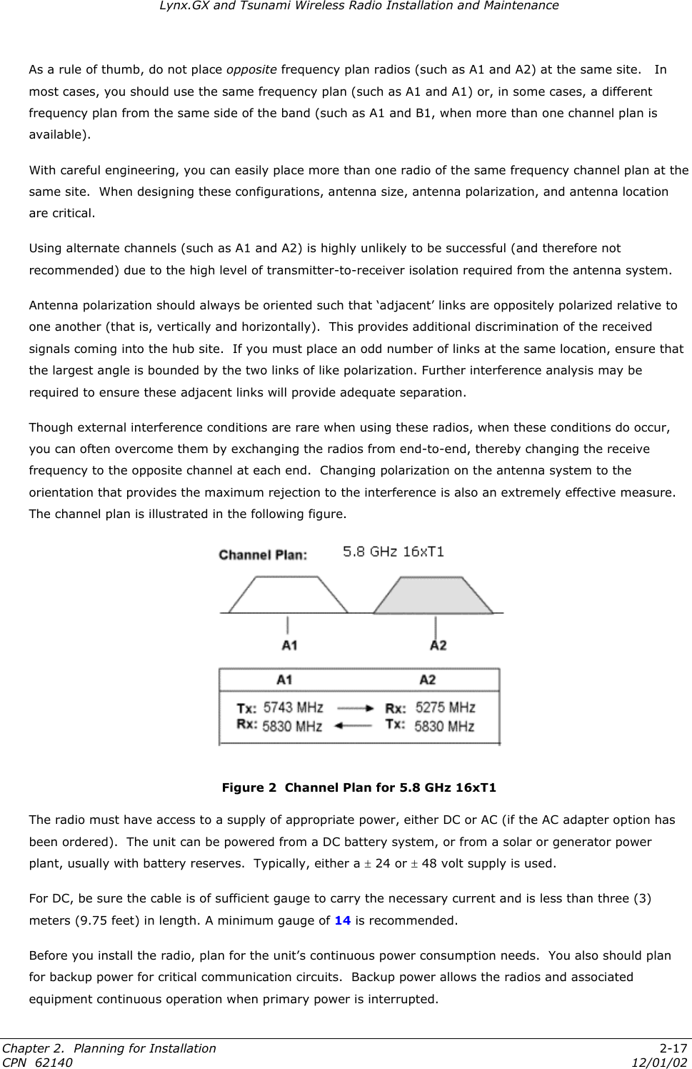
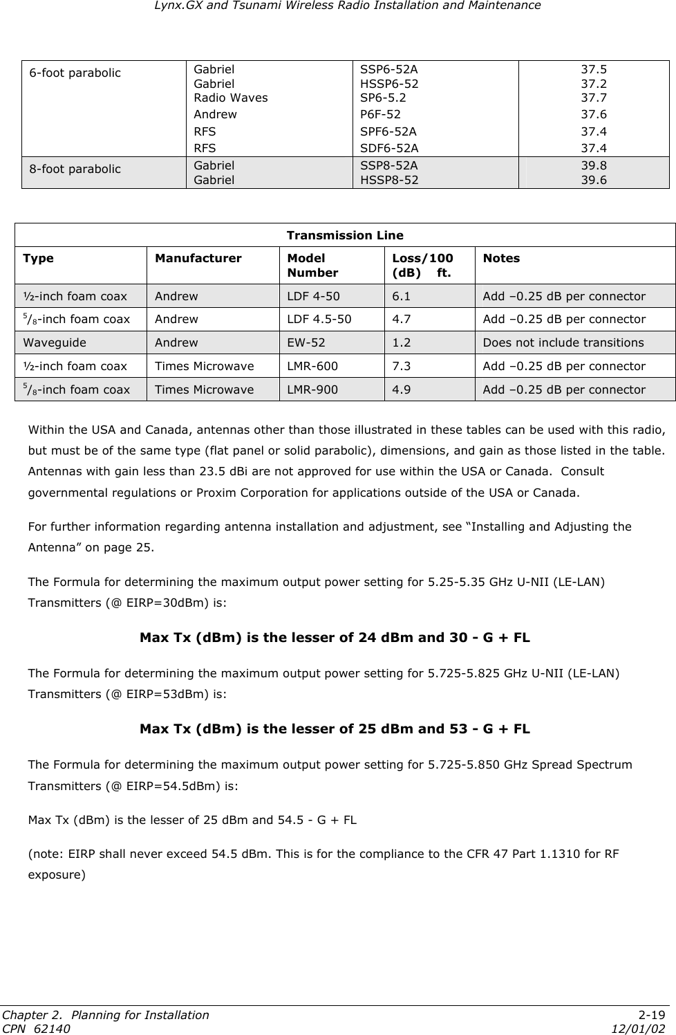
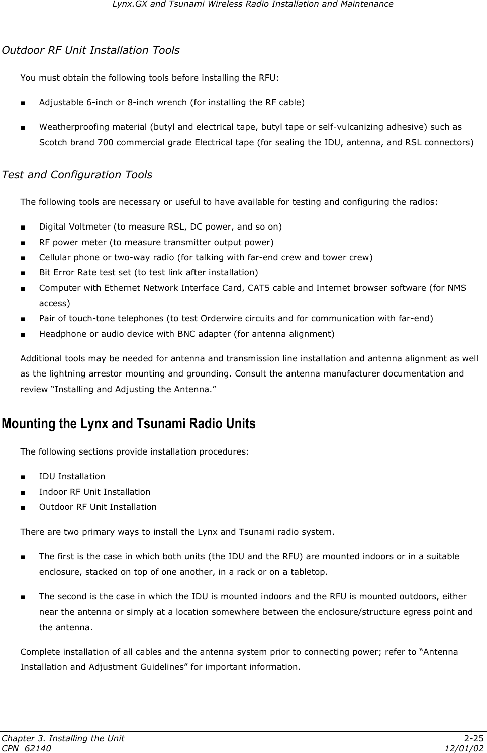
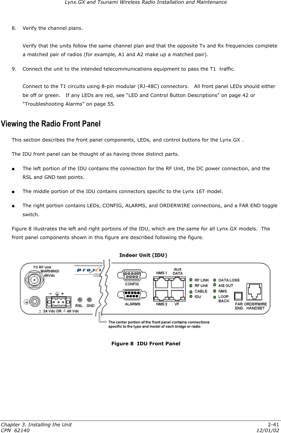
![Lynx.GX and Tsunami Wireless Radio Installation and Maintenance Basic Specifications for Lynx.GX models Bandwidth (MHz) Typical Output Power Chnl Plans Main Interface Connectors Aggreg. Capacity (Mbsp) Line Code/ Channel Line Buildout/ channel 8 T1 125 13.5 AMI/B8ZS 8 E1 100 or 125 2 DSX-1 [RJ48c] 18 4 T1/E1 3 DSX-1 [RJ48c]; CEPT-1 [RJ48c or 2xBNC] 9 16 T1 12 E1 125 ≥20 dBm 27 DS-3 28 T1 21 E1 100 ≥17 dBm 1 DSX-1 and CEPT-1: using 64 pin DSX connector 54 18 AMI/B8ZS; HDB3 0–600 ft., selectable Tsunami Models The following tables list the Tsunami models as well as some of their basic specifications. For full specifications, see “Appendix C. Product Specifications.”. Model Number Manufacturing Part Number Ports Frequency Compliance 51145-41L0 51145-41H0 TBD TBD 10/100 Base-T, 100 Base-FX, plus T1 port (10 Mbps) 5.8 GHz ISM 51145-42L0 51145-42H0 TBD TBD 10/100 Base-T, 100 Base-FX, plus E1 port (10 Mbps) 5.8 GHz ISM 57710-51L0 57710-51H0 TBD TBD 10/100 Base-T, 100 Base-FX, plus 2 T1 ports (45 Mbps) 5.8 GHz U-NII 57710-52L0 57710-52H0 TBD TBD 10/100 Base-T, 100 Base-FX, plus 2 E1 ports (45 Mbps) 5.8 GHz U-NII 57750-51L0 57750-51H0 TBD TBD 10/100 Base-T, 100 Base-FX, plus 2 T1 ports (45 Mbps) 5.3 GHz U-NII 57750-52L0 57750-52H0 TBD TBD 10/100 Base-T, 100 Base-FX, plus 2 E1 ports (45 Mbps) 5.3 GHz U-NII Chapter 1. Introduction 1-10 CPN 62140 12/01/02](https://usermanual.wiki/Proxim-Wireless/US5358-GX1/User-Guide-290919-Page-10.png)
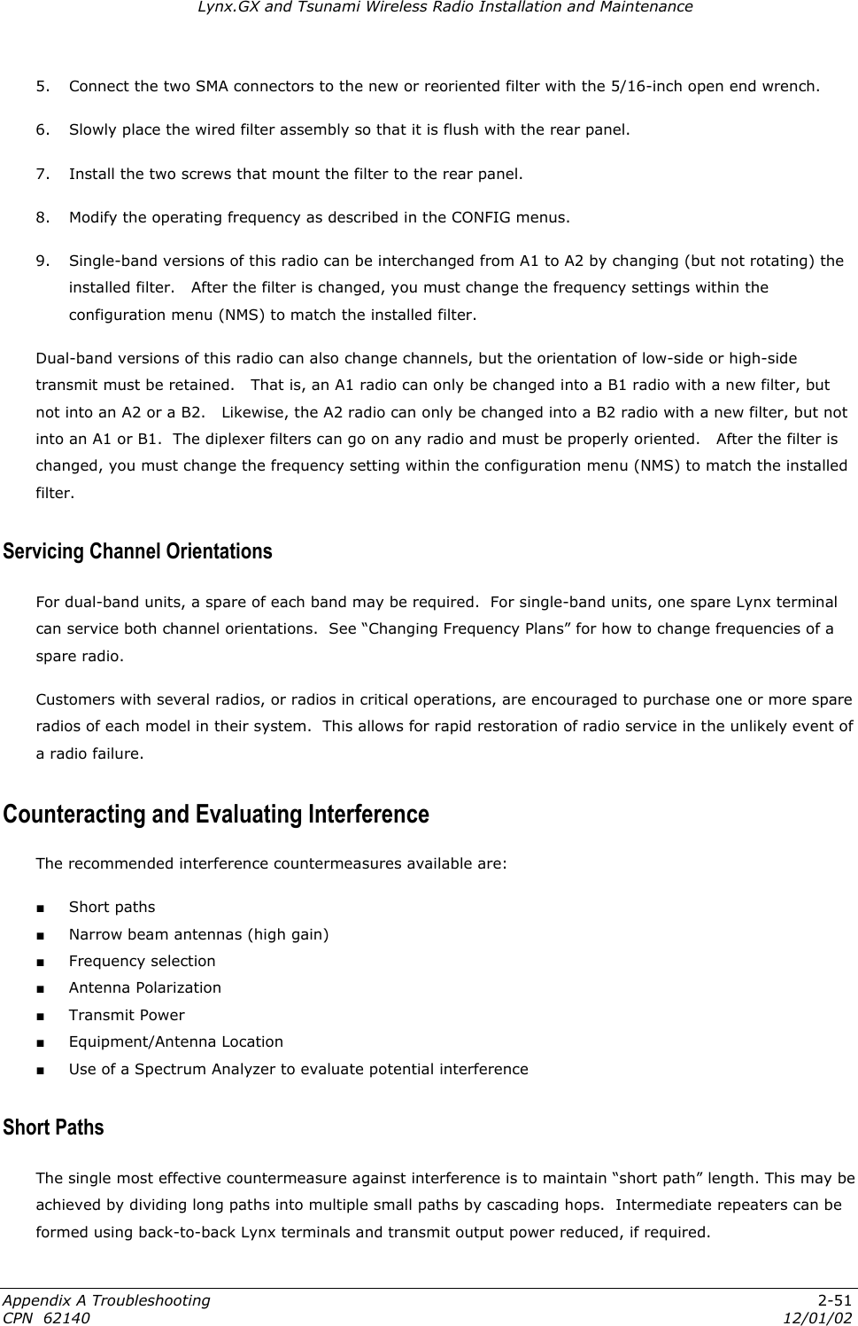
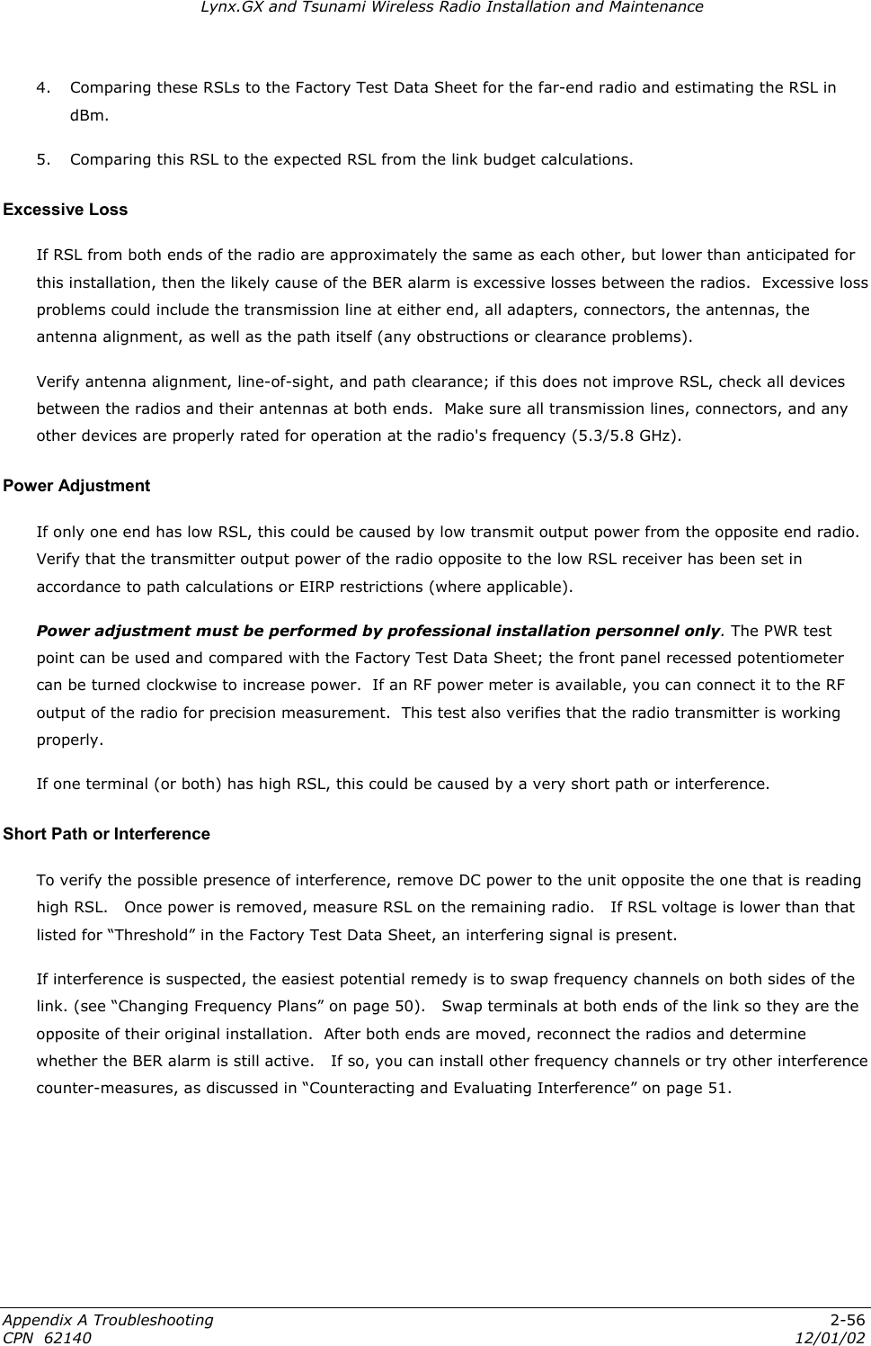
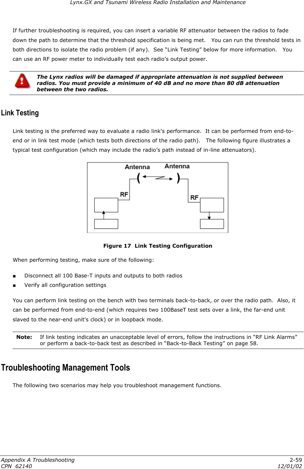
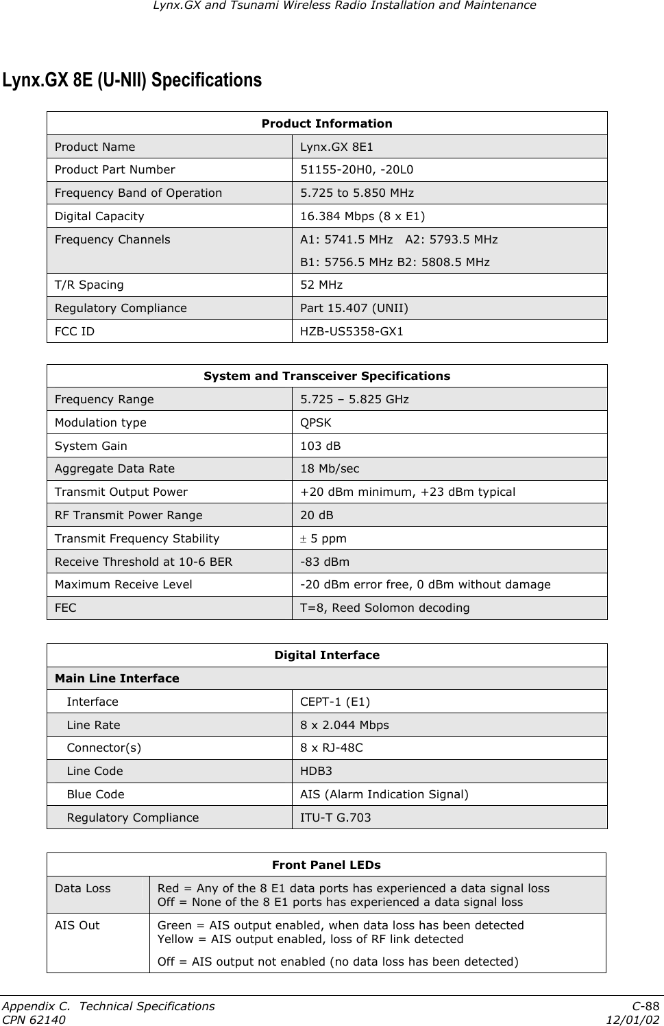
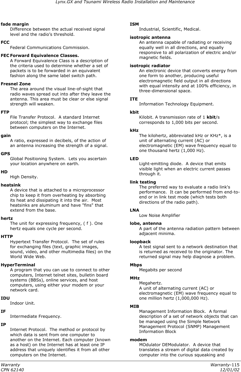
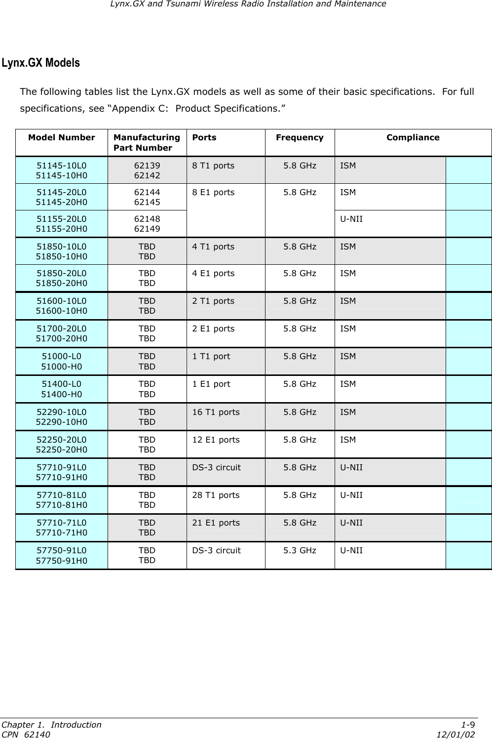
![Lynx.GX and Tsunami Wireless Radio Installation and Maintenance ORDERWIRE HANDSET This connection is used to access the electronic orderwire function (a facility for telephone style service from one radio to another). A standard analog telephone (with an electronic ringer) plugs into this connector. You can dial the orderwire address of the far-end radio (or any radio in the network) to cause that radio and any connected orderwire phone to ring; however, communications is automatically established when both handsets are lifted off hook. This communication does not interrupt or interfere with the other radio communications. The radio link must be operational to use this facility. The orderwire feature can be very useful for installation, maintenance, and troubleshooting. Note: All Lynx radios connected to the same orderwire network should have unique address settings (telephone numbers). Establishing Near-End to Far-End Communications using Orderwire To establish near-end to far-end communications using orderwire: 1. Connect the telephone to the near-end and far-end radios. Using a standard RJ-11 telephone cable, connect a standard electronic telephone (a touch tone phone, complete with dialer) to the Orderwire connector on the radio front panel. This connector is wired identically to a standard two-wire telephone jack. For connector pin assignment, see “Appendix B. Connectors and Pin Assignments” on page 63. 2. Call the far-end radio. With a telephone connected to each radio on opposite ends of the link, either telephone can be used to dial-up the far-end location. The far-end radio internal ringer and the connected telephone ring, and if answered, two-way full-duplex voice communication is established. If the radios are connected in a repeater configuration, you can establish Orderwire services in the network by connecting the radios (by cabling their front-panel VF connectors). Orderwire operates on radios at each end of the repeater and at the repeater site. You can extend this function through several repeater sites. For hub connections of three or more Lynx radios, an external 4-wire radio is required to connect all devices for Orderwire operations. Dialing an * [asterisk/star key] on the orderwire telephone implements an “all call” feature that rings all connected radios. All telephones provide communication to all other telephones in the connected network. Even if a particular telephone does not ring, it can still be used to talk and listen to any ongoing orderwire activity if the orderwire is in use at other terminal locations. Also, if a phone anywhere in the connected network has accidentally been left off-hook, the # [pound] key can be used to mute all off-hook handsets until they are placed on and off hook again. Chapter 3. Installing the Unit 2-44 CPN 62140 12/01/02](https://usermanual.wiki/Proxim-Wireless/US5358-GX1/User-Guide-290919-Page-44.png)