Proxim Wireless US5358-GX1 Unlicensed NII Transceiver User Manual Backing down from TNG CCI 2
Proxim Wireless Corporation Unlicensed NII Transceiver Backing down from TNG CCI 2
Installation Manual

Lynx.GX Wireless Radios
Tsunami Wireless Ethernet Bridges
Installation and Maintenance
CPN 62140
Issue Date: 12/01/02

Lynx.GX and Tsunami Radio Installation and Configuration
Notices
Copyright and Service Marks
Copyright © 2002 by Proxim. All rights reserved. No part of this book may be reproduced without prior
written permission from Proxim.
The information contained in this book is subject to change without notice. Proxim shall not be liable for
errors contained herein or for incidental or consequential damages in connection with the furnishing,
performance, or use of this book or equipment supplied with this book. Proxim makes no warranty of any
kind with regard to this book or any equipment supplied with this book, including, but not limited to, the
implied warranties of merchantability and fitness for a particular purpose.
Lynx™ is a trademark of Proxim Corporation.
Tsunami™ is a trademark of Proxim Corporation.
HELIAX® is a registered trademark of Andrews Corporation.
OpenView® is a registered trademark of Hewlett Packard Corporation.
SmartBits® is a registered trademark of Spirent Systems, Inc.
Windows® is a registered trademark of Microsoft Corporation.
Chariot® and Qcheck® are registered trademarks of NetIQ Corporation.
Gabriel HE or HES parabolic antennas are products of Gabriel Electronics, Inc.
Other names are trademarks of their respective owners.
Y2K (Year 2000 Issue): All software supplied by and for Proxim products adhere to the 4-digit year
nomenclature as required for Year 2000 compliance.
Regulatory Notice
This equipment has been tested and found to comply with the limits for a Class A digital device,
pursuant to part 15 of the FCC Rules. These limits are designed to provide reasonable protection
against harmful interference when the equipment is operated in a commercial environment. This
equipment generates, uses, and can radiate radio frequency energy and, if not installed and used in
accordance with the instruction manual, may cause harmful interference to radio communications.
Operation of this equipment in a residential area is likely to cause harmful interference in which case
the user will be required to correct the interference at his own expense.
Shielded cables and I/O cords must be used for this equipment to comply wit the relevant FCC regulations.
Changes or modifications not expressly approved in writing by Proxim may void the user’s authority to
operate this equipment.
Notices 2
CPN 62140 12/01/02

Lynx.GX and Tsunami Wireless Radio Installation and Maintenance
This device complies with Part 15 of FCC rules and RSS-210 of Industry Canada. Operation is subject to the
following two conditions: (1) this device may not cause interference, and (2) this device must accept any
interference, including interference that may cause undesired operation of the device.
This device must be installed professionally.
Notices 3
CPN 62140 12/01/02

Lynx.GX and Tsunami Radio Installation and Configuration
Contents
NOTICES ......................................................................................................................................... 2
Copyright and Service Marks ..........................................................................................................2
Regulatory Notice .........................................................................................................................2
CONTENTS....................................................................................................................................... 4
ABOUT THIS BOOK .......................................................................................................................... 7
Intended Audience ........................................................................................................................7
Support .......................................................................................................................................7
CHAPTER 1. INTRODUCTION .......................................................................................................... 8
Basic Equipment Features ..............................................................................................................8
Lynx.GX Models......................................................................................................................9
Tsunami Models ................................................................................................................... 10
Product Safety Instructions .......................................................................................................... 11
Grounding ........................................................................................................................... 13
CHAPTER 2. PLANNING FOR INSTALLATION ................................................................................ 14
Selecting a Site .......................................................................................................................... 14
Line-of-Sight and Path Clearance Guidelines ............................................................................ 14
Calculating Availability................................................................................................................. 15
Calculating Received Signal Level and Link Budget.......................................................................... 15
Calculating Fade Margin............................................................................................................... 16
Determining the Frequency Plan ................................................................................................... 16
Planning for Antenna Installation .................................................................................................. 18
Reviewing the Installation Process ................................................................................................ 20
1. Test radios back-to-back and configure .............................................................................. 20
2. Mount antennas............................................................................................................... 20
3. Run transmission line route and egress, including lightning arrestors ..................................... 20
4. Connect radios to antennas and power, including grounding.................................................. 20
5. Align antennas ................................................................................................................ 21
6. Check RSL against predicted results, iterate, and troubleshoot .............................................. 21
7. Troubleshooting............................................................................................................... 22
8. Connect services and test connectivity ............................................................................... 22
Helpful Hints .............................................................................................................................. 22
CHAPTER 3. INSTALLING THE UNITS ........................................................................................... 23
Mounting the Units...................................................................................................................... 23
Assembling Required Materials ............................................................................................... 23
Required Tools ..................................................................................................................... 24
Mounting the Lynx and Tsunami Radio Units .................................................................................. 25
Installing the Indoor Unit ............................................................................................................. 26
Installing the RF Unit in an Outdoor Configuration........................................................................... 28
Installing and Adjusting the Antenna ............................................................................................. 30
Antenna Installation.............................................................................................................. 30
Alignment Guidelines ............................................................................................................31
RSL Voltage Guidelines ......................................................................................................... 32
Establishing Connections ............................................................................................................. 33
Antenna Connection..............................................................................................................33
Antenna Cabling Guidelines for 5.8 GHz Units .......................................................................... 34
Transmission Line Connection ................................................................................................ 34
Power Connections ...............................................................................................................36
Adjusting Output Power ............................................................................................................... 38
Establishing a Connection Between the Units.................................................................................. 38
Viewing the Radio Front Panel ...................................................................................................... 41
Control Button and LED Descriptions....................................................................................... 42
Port/Circuit Connections by Model .......................................................................................... 45
APPENDIX A. TROUBLESHOOTING ............................................................................................... 49
Maintaining the Radio.................................................................................................................. 49
Data Stream Errors ..................................................................................................................... 49
Changing Frequency Plans ........................................................................................................... 50
Servicing Channel Orientations............................................................................................... 51
Counteracting and Evaluating Interference..................................................................................... 51
Contents 4
CPN 62140 12/01/02

Lynx.GX and Tsunami Wireless Radio Installation and Maintenance
Short Paths.......................................................................................................................... 51
Narrow Beam Antennas (High Gain)........................................................................................ 52
Frequency Selection.............................................................................................................. 52
Antenna Polarization ............................................................................................................. 53
Transmit Power .................................................................................................................... 54
Equipment/Antenna Location ................................................................................................. 54
Use of a Spectrum Analyzer to Evaluate Potential Interference ................................................... 54
Troubleshooting Alarms ............................................................................................................... 55
RF Link Alarm ...................................................................................................................... 55
Radio Fail Alarms.................................................................................................................. 57
Far End Alarms .................................................................................................................... 57
Measuring Radio Function ............................................................................................................ 58
Back-to-Back Testing ............................................................................................................58
Link Testing ......................................................................................................................... 59
Troubleshooting Management Tools .............................................................................................. 59
Troubleshooting the Console Management Tool ........................................................................ 60
Troubleshooting the Web Interface Management Tool...................................................................... 61
Repair Policy .............................................................................................................................. 61
APPENDIX B. CONNECTORS AND PIN ASSIGNMENTS ................................................................... 63
IDU Main Traffic T1/E1 Connection................................................................................................ 63
IDU VF Port................................................................................................................................ 64
IDU Aux Data Port ...................................................................................................................... 65
IDU NMS Port............................................................................................................................. 66
IDU Alarm Port Connector and Pin Assignment ............................................................................... 67
IDU Configuration Port Connector and Pin Assignment..................................................................... 68
IDU Orderwire Handset Port ......................................................................................................... 69
IDU/RFU Cable Connector and Pin Assignment ............................................................................... 70
RSL and GND Connectors............................................................................................................. 71
RFU/Antenna Connector and Pin Assignment .................................................................................. 72
RFU RSL/Tone and Pin Assignment ............................................................................................... 73
APPENDIX C. TECHNICAL SPECIFICATIONS ................................................................................. 74
Lynx.GX General Specifications .................................................................................................... 74
Lynx.GX 28T1 and Lynx.GX DS-3 (U-NII 5.8 GHz) Specifications ..................................................... 79
Lynx.GX 21E1 (U-NII 5.8 GHz) Specifications ................................................................................. 81
Lynx.GX 16T1 and Lynx.GX 12E1 (ISM) Specifications.................................................................... 83
Lynx.GX 8T (ISM) Specifications ................................................................................................... 85
Lynx.GX 8E ISM Specifications ..................................................................................................... 87
Lynx.GX 8E (U-NII) Specifications................................................................................................. 88
Lynx.GX 4T1 and Lynx.GX 4E1 (ISM) Specifications ........................................................................ 89
Lynx.GX 2T1 and Lynx.GX 2E1 (ISM) Specifications ....................................................................... 91
Lynx.GX T1 and Lynx.GX E1 (ISM) Specifications........................................................................... 93
Lynx.GX DS-3 (U-NII 5.3 GHz) Specifications ................................................................................. 95
Tsunami General Specifications .................................................................................................... 97
Tsunami 20 + 2T1 and Tsunami 20 + 2E1 Specifications ............................................................... 102
Tsunami 90 +2T1 and Tsunami 90 +2E1 (U-NII 5.8 GHz) Specifications ........................................ 104
Tsunami 90 +2T1 and Tsunami 90 +2E1 (U-NII 5.3 GHz) Specifications ......................................... 106
WARRANTY ..................................................................................................................................108
ACRONYMS / GLOSSARY ..............................................................................................................113
Figures
Figure 1 Proper Equipment Earthing/Grounding ...................................................................................13
Figure 2 Channel Plan for 5.8 GHz 16xT1 ............................................................................................ 17
Figure 3 Shipping Container Contents for 2-Piece Radios....................................................................... 23
Figure 4 Typical RSL Voltage vs. Receive RSL ...................................................................................... 32
Figure 5 Negative Voltage DC Connection............................................................................................ 36
Figure 6 Positive Voltage DC Connection ............................................................................................. 36
Figure 7 Power Connection for IDU..................................................................................................... 37
Figure 8 IDU Front Panel................................................................................................................... 41
Figure 9 IDU Front Panel – Data Interface (Middle section).................................................................... 45
Figure 10 12xE1 Radio Connections.................................................................................................... 46
Figure 11 4xT1 and 4xE1 Connections ................................................................................................ 46
Figure 12 8xT1/8xE1 Digital Radio Connections ................................................................................... 46
Contents 5
CPN 62140 12/01/02

Lynx.GX and Tsunami Wireless Radio Installation and Maintenance
Figure 13 DS-3 Digital Radio Connections ........................................................................................... 46
Figure 14 16xT1 Digital Radio Connections .......................................................................................... 47
Figure 15 21xE1 and 28xT1 Connections............................................................................................. 47
Figure 16 Back-to-Back Test Configuration .......................................................................................... 58
Figure 17 Link Testing Configuration................................................................................................... 59
Contents 6
CPN 62140 12/01/02

Lynx.GX and Tsunami Radio Installation and Configuration
About This Book
This book provides the information needed to install, maintain, and troubleshoot the Lynx.GX and Tsunami
(GX platform) Radios.
Be sure to read “Product Safety Instructions” in Chapter 1 before installing this product.
This device must be professionally installed. Instructions for setting the transmitter RF
output power are referenced in “Output Power Adjustment.”
This device is to be used exclusively for fixed point-to-point operation that employs
directional antennas.
Intended Audience
This book is designed for network engineers and field service personnel responsible for installing,
maintaining, and troubleshooting the Lynx.GX and Tsunami wireless radios. It is assumed you have an
understanding of networks in general and a basic understanding of the following subjects:
■ Microwave fundamentals
■ Microwave test equipment
■ T1/E1, DS-3
■ Ethernet, Fast Ethernet
■ IP networking
Support
For technical support, contact Proxim Technical Support at WANSUPPORT@proxim.com or at 1-408-542-
5390.
About This Book 7
CPN 62140 12/01/02

Lynx.GX and Tsunami Radio Installation and Configuration
Chapter 1. Introduction
Proxim Corporation introduces the GX platform of wireless bridge products - Lynx.GX wireless radios and the
Tsunami wireless bridges. The split-box design lets you install both units indoors, or one unit indoors (the
IDU, or indoor unit) and one unit outdoors (the RFU, or RF Unit).
The units can be mounted in a 19-inch rack; each piece is 1.75” high, occupying one rack unit (RU). Two
pieces fit in two rack unit spaces for indoor installation, or you can mount the RF processor unit outdoors on
a pole.
The units then are connected to one another with an IF coaxial cable; the antenna is connected to the
outdoor unit. The outdoor unit directly contributes to significant cost savings of cable and antennas,
improved system availability, and enhanced path performance.
A simplified and standardized user interface for product management is provided across all models, with a full
network management system (NMS) for remote equipment management.
Basic Equipment Features
The following features apply to the GX product series:
■ Split Box design with IDU Modem and RDU unit for addressing user’s budget, maintenance, and
performance requirements
■ User selectable channel plans
■ Full featured Fault and Configuration Management via web browser, SNMP, Telnet, or serial connection
■ Advanced diagnostics – spectrum analyzer, RSL time strip charting, alarm logging
■ Voice and data interfaces – T1 or E1 or 10/100BT –available up to 45 Mbps aggregate capacity, full
duplex
■ Auxiliary interfaces include wayside T1 or E1 channels for selected models, serial data port, and
orderwire connection (VF bridge)
■ Link ID authentication algorithm to insure highly secure link transmission
■ Models ranging in capacity from 1T1 to DS-3, 10/100BaseT (45 Mbps)
Chapter 1. Introduction 1-8
CPN 62140 12/01/02

Lynx.GX and Tsunami Wireless Radio Installation and Maintenance
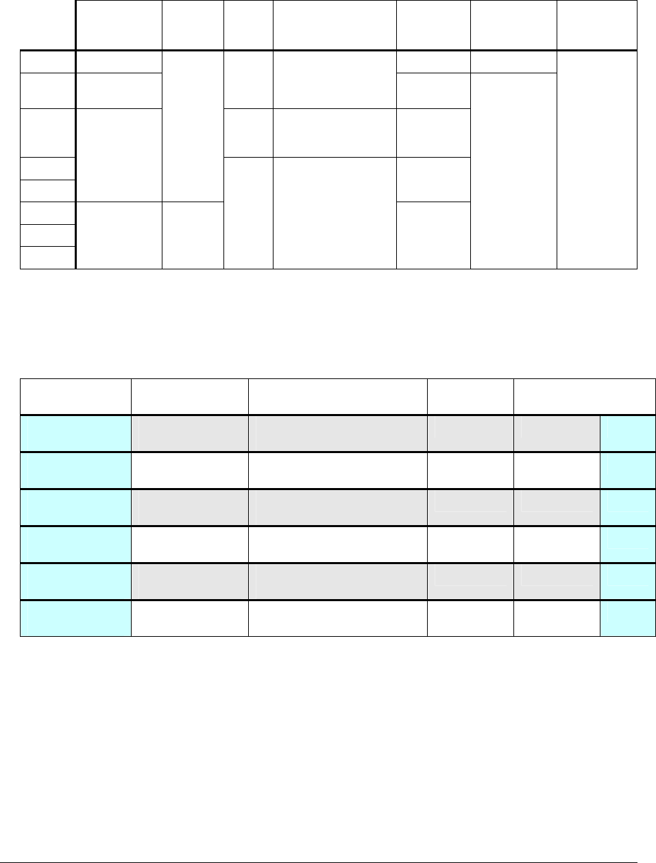
Lynx.GX Models
The following tables list the Lynx.GX models as well as some of their basic specifications. For full
specifications, see “Appendix C: Product Specifications.”
Model Number Manufacturing
Part Number
Ports Frequency Compliance
51145-10L0
51145-10H0
62139
62142
8 T1 ports 5.8 GHz ISM
51145-20L0
51145-20H0
62144
62145
ISM
51155-20L0
51155-20H0
62148
62149
8 E1 ports 5.8 GHz
U-NII
51850-10L0
51850-10H0
TBD
TBD
4 T1 ports 5.8 GHz ISM
51850-20L0
51850-20H0
TBD
TBD
4 E1 ports 5.8 GHz ISM
51600-10L0
51600-10H0
TBD
TBD
2 T1 ports 5.8 GHz ISM
51700-20L0
51700-20H0
TBD
TBD
2 E1 ports 5.8 GHz ISM
51000-L0
51000-H0
TBD
TBD
1 T1 port 5.8 GHz ISM
51400-L0
51400-H0
TBD
TBD
1 E1 port 5.8 GHz ISM
52290-10L0
52290-10H0
TBD
TBD
16 T1 ports 5.8 GHz ISM
52250-20L0
52250-20H0
TBD
TBD
12 E1 ports 5.8 GHz ISM
57710-91L0
57710-91H0
TBD
TBD
DS-3 circuit 5.8 GHz U-NII
57710-81L0
57710-81H0
TBD
TBD
28 T1 ports 5.8 GHz U-NII
57710-71L0
57710-71H0
TBD
TBD
21 E1 ports 5.8 GHz U-NII
57750-91L0
57750-91H0
TBD
TBD
DS-3 circuit 5.3 GHz U-NII
Chapter 1. Introduction 1-9
CPN 62140 12/01/02
Lynx.GX and Tsunami Wireless Radio Installation and Maintenance
Basic Specifications for Lynx.GX models
Bandwidth
(MHz)
Typical
Output
Power
Chnl
Plans
Main Interface
Connectors
Aggreg.
Capacity
(Mbsp)
Line Code/
Channel
Line
Buildout/
channel
8 T1 125 13.5 AMI/B8ZS
8 E1 100 or 125
2
DSX-1 [RJ48c]
18
4
T1/E1
3
DSX-1 [RJ48c];
CEPT-1 [RJ48c or
2xBNC]
9
16 T1
12 E1
125
≥20
dBm
27
DS-3
28 T1
21 E1
100 ≥17
dBm
1
DSX-1 and CEPT-1:
using 64 pin DSX
connector
54
18
AMI/B8ZS;
HDB3
0–600 ft.,
selectable
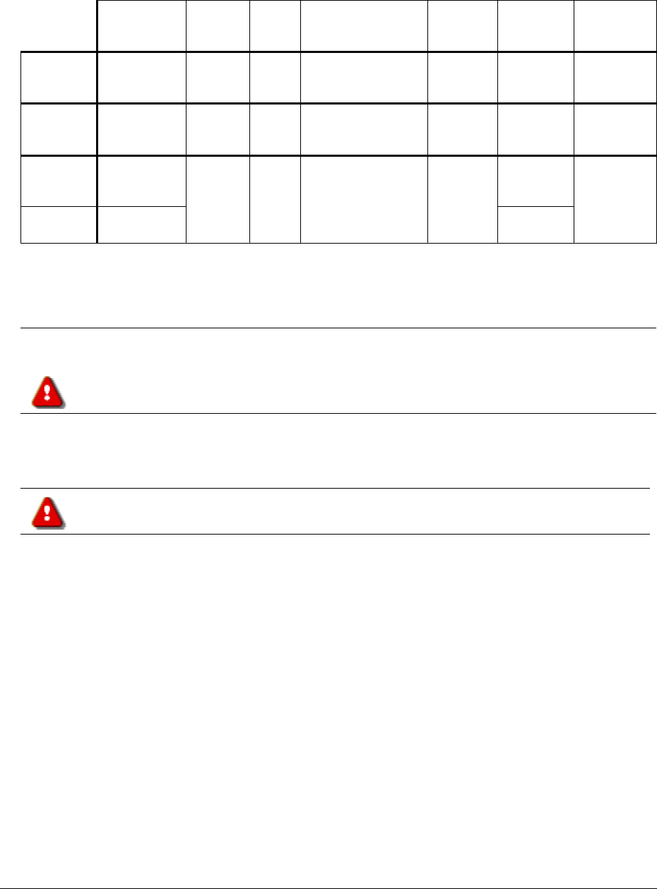
Tsunami Models
The following tables list the Tsunami models as well as some of their basic specifications. For full
specifications, see “Appendix C. Product Specifications.”.
Model Number
Manufacturing
Part Number
Ports
Frequency
Compliance
51145-41L0
51145-41H0
TBD
TBD
10/100 Base-T, 100 Base-FX,
plus T1 port (10 Mbps)
5.8 GHz ISM
51145-42L0
51145-42H0
TBD
TBD
10/100 Base-T, 100 Base-FX,
plus E1 port (10 Mbps)
5.8 GHz ISM
57710-51L0
57710-51H0
TBD
TBD
10/100 Base-T, 100 Base-FX,
plus 2 T1 ports (45 Mbps)
5.8 GHz U-NII
57710-52L0
57710-52H0
TBD
TBD
10/100 Base-T, 100 Base-FX,
plus 2 E1 ports (45 Mbps)
5.8 GHz U-NII
57750-51L0
57750-51H0
TBD
TBD
10/100 Base-T, 100 Base-FX,
plus 2 T1 ports (45 Mbps)
5.3 GHz U-NII
57750-52L0
57750-52H0
TBD
TBD
10/100 Base-T, 100 Base-FX,
plus 2 E1 ports (45 Mbps)
5.3 GHz U-NII
Chapter 1. Introduction 1-10
CPN 62140 12/01/02
Lynx.GX and Tsunami Wireless Radio Installation and Maintenance
Basic Specifications for Tsunami models
Bandwidth
(MHz)
Typical
Output
Power
Chnl
Plans
Main Interface
Connectors
Aggreg.
Capacity
(Mbsp)
Line
Code /
Channel
Line
Buildout/
channel
10/100
+2T1
125 ≥20
dBm
2 10/100 Base-TX
RJ-45 female;
Fiber SC
>20 AMI/B8ZS
for
wayside
0–655 ft.,
selectable,
for wayside
10/100
+2E1
125 ≥20
dBm
2 10/100 Base-TX
RJ-45 female;
Fiber SC
>20 HBD3 for
wayside
100/100
+ 2 T1
100 AMI/B8ZS
for
wayside
100/100
+ 2 E1
100
≥ 17
dBm
1 10/100 Base-TX
RJ-45 female;
Fiber SC
> 108
HBD3 for
wayside
0–655 ft.,
selectable,
for wayside
Product Safety Instructions
This product should be installed, used, and maintained by experienced telecommunications personnel only.
This unit should be installed in a Restricted Access location in accordance with Articles 110-28,
110-26, and 110-27 of the United States National Electric Code ANSI/NFPA 70.
This equipment should be installed in accordance with Article 810 of the United States National
Electrical Code.
When installed, this equipment is to be connected to a Lightning/Surge Protection Device that meets all
applicable national Safety requirements.
To avoid injury, risk of fire, and damage, do not connect this product directly to an antenna.
Ensure that proper lightning isolation is also provided between this unit and other equipment.
Equipment is to be used and powered by the type of power source indicated on the marking label only.
Lynx radios are intended to be connected to a ± 24 VDC or ± 48 VDC power source, which must be electrically
isolated form any AC sources and reliably earthed.
Only a DC power source that complies with the Safety Extra Low Voltage (SELV) requirements in the
Standard for the Safety of Information Technology Equipment, including Electrical Business Equipment,
CAN/CSA C22.2, No. 950-95 * UL 1950, Third Edition, can be used with this product.
A 15-Amp circuit breaker is required at the power source. In addition, an easily accessible disconnect device
should be incorporated into the facility wiring.
Always use copper conductors only for all power connections.
Do not connect or disconnect the power cable to the equipment when the other end of the cable is connected
to the DC power supply.
Chapter 1. Introduction 1-11
CPN 62140 12/01/02
Lynx.GX and Tsunami Wireless Radio Installation and Maintenance
This product must be serviced by trained personnel only.
Do not:
• Disassemble this product. By opening or removing any covers, you could expose yourself to hazardous
energy parts. Incorrect reassembly of this product can cause a malfunction or electrical shock when the
unit subsequently is used.
■ Insert any objects of any shape or size inside this product while powered. Objects could contact
hazardous energy parts, resulting in a risk of fire or personal injury.
■ Spill any liquids of any kind on or inside this product.
■ Cover or block any of the openings (to protect this product from overheating). Side openings are
provided for ventilation.
Always ensure the following:
■ Always ensure that sufficient space is provided above and below this product.
This product can be installed in a standard 19-inch rack. Check the size and clearance requirements for
this product and ensure that enough clearance is provided for installation. Consideration should be given
to the mechanical loading of the rack and the equipment to avoid potential hazards.
■ If this product is to be powered from the same source as other units, ensure that the power supply
circuit is not overloaded.
■ When installed in a rack, always ensure that proper air flow is provided for this product.
■ If you are using a handset not provided by Proxim with this product, ensure that the handset is a UL-
Listed (ITE) device that has been evaluated to the Standard for the Safety of Information Technology
Equipment, including Electrical Business Equipment, CAN/CSA C22.2, No. 950-85 * UL 1950, Third
Edition.
The maximum room ambient temperature (Tmra) for this product is 65° C. When installed in a closed or
multiunit rack, consideration should be given to installing this equipment in an environment compatible with
the Tmra.
Equipment is suitable for mounting on concrete or other noncombustible surfaces only.
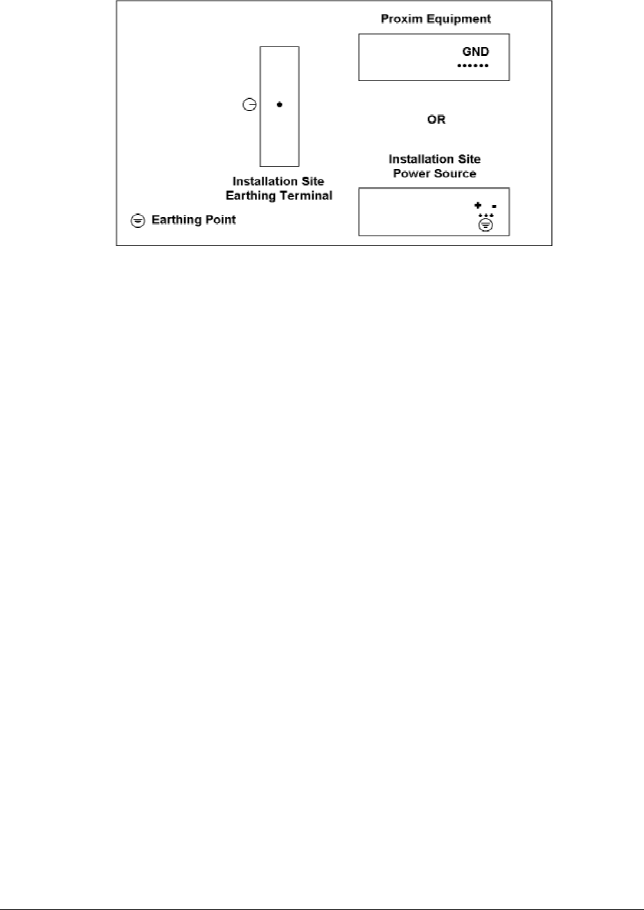
This equipment must be earthed. If you are not using the power supply provided by
Proxim, you must connect the earthing conductor of your power source to the earthing
terminal located on the back of the unit; or, connect an earthing conductor between the
unit’s earthing terminal and your earthing point. For safe operation, always ensure
that the unit is earthed properly, as described in this book and shown in the following
figure.
Chapter 1. Introduction 1-12
CPN 62140 12/01/02
Lynx.GX and Tsunami Wireless Radio Installation and Maintenance
Figure 1 Proper Equipment Earthing/Grounding
Grounding
Be sure to:
■ Use a common ground for everything
■ Ground the radio to the rack
Be careful with DC power grounding:
■ Grounding DC supply may create ground loops
■ If DC source is referenced to ground, use DC power and jumper to ground
■ Best if DC source “floats” in case of lightning or other surge
Other grounding:
■ Mast
■ Transmission line
Chapter 1. Introduction 1-13
CPN 62140 12/01/02

Lynx.GX and Tsunami Radio Installation and Configuration
Chapter 2. Planning for Installation
There are several planning factors to be considered prior to installing the Tsunami or Lynx radio system.
In addition to selecting the installation site, you must:
Calculate:
º Predicted Path Availability
º Anticipated RSL and Fade Margin
Determine:
º Frequency Plan
º Required Antenna Size and Type
º Required Transmission Line Types and Lengths
Plan for:
º The unit’s continuous power consumption needs
º Antenna installation
º Lightning protection and system grounding
º Radio hardware mounting
º Cable installation including egress
Also, before installing the system, you may want to perform a back-to-back test of the radio pair. Back-to-
back testing is a simple way to verify that the radios are fully operational before they are installed. The
process of installation adds several variables (such as antenna alignment and path dynamics) which can lead
to system turn-up delays during troubleshooting. By pre-testing the radios, you reduce the chance of their
being the cause of system turn-up problems, so you can focus on other factors, such as transmission line,
antenna alignment, path clearance, and other factors. See “Back-to-Back Testing” on page 58.
Selecting a Site
The radio site must have:
■ Access to appropriate power
■ Access to the telecommunications system you want to interconnect
■ Line-of-sight to the other radio location with adequate path clearance
■ Location for mounting the antenna
Line-of-Sight and Path Clearance Guidelines
The frequencies of these radio transmissions are not intended to pass through trees or other obstacles.
Factors to consider include earth curvature, future growth of trees, and height of buildings. In addition to the
line-of-sight requirement, a well-engineered path has additional path clearance to allow for signal loss due to
partial obstructions, atmospheric ducting, and ground reflections.
Chapter 2. Planning for Installation 2-14
CPN 62140 12/01/02

Lynx.GX and Tsunami Wireless Radio Installation and Maintenance
To maximize link availability, calculate 0.6 times the first Fresnel zone and add this value to path clearance
based upon the primary path (in addition to earth curvature, trees, buildings, and so on).
The radios will not perform properly unless they have line-of-sight and proper path clearance between their
corresponding antennas.
Calculating Availability
Availability of the microwave path is a prediction of the percent of time that the link operates without
producing an excessive bit error rate (BER) due to multipath fading. In the absence of direct interference,
availability is affected by the following:
■ Path length
■ Fade margin
■ Frequency
■ Terrain (smooth, average, mountainous)
■ Climate (dry, temperate, humid)
Depending upon the type of information carried over the link and the overall network design redundancy, you
may want to design for a specific availability rate. For example, if the data or voice traffic carried by the
radio is critical, the link can be designed for a very high availability rate (for example, 99.999% or 5.3
minutes of predicted outage per year).
Availability can be improved by increasing the fade margin either by making the path shorter or by using
higher gain antennas in conjunction with lower loss transmission line (using a higher quality transmission
line, shortening the length, or both).
Calculating Received Signal Level and Link Budget
Use the following formula to estimate the received signal level (RSL):
RSL (dBm) = Pout - L1+ G1 + G2 - L2 - Lp
where:
Pout is the transmitter output power (in dBm)
L1 is the total loss of all transmission elements between the antenna and the RF Unit on
one side of the link (in dB)
G1 is the gain of the antenna on one side of the link (in dB)
G2 is the gain of the antenna on the opposite side of the link (in dB)
L2 is the total loss of all transmission elements between the antenna and the RF Unit on
the opposite side of the link (in dB)
Chapter 2. Planning for Installation 2-15
CPN 62140 12/01/02

Lynx.GX and Tsunami Wireless Radio Installation and Maintenance
Lp is the Path loss, defined by:
Lp (dB) = 96.6 + 20 log10F + 20 log10D
where:
F is the Frequency of the radio system in GHz (5.8 in the case of this model)
D is the Distance of the path in miles
The results of this link budget calculation are very important for determining any potential problems during
installation. If you have calculated the expected RSL, you can verify that it has been achieved during
installation and troubleshooting, if necessary.
In the USA and Canada, this model radio can be installed with any gain directional antennas, as there is no
Effective Isotropic Radiated Power (EIRP) limit for the application of these systems for fixed point-to-point
applications. In other countries, EIRP limits may apply.
In the case of EIRP limits, use the lesser of either (Pout - L1+ G1) or the EIRP limit within the previous
equation. You may have to check this equation in both directions to assure legal application.
An EIRP limit is the maximum RF energy allowed to be transmitted, as measured at the transmitting antenna,
and is usually determined by government regulations.
Calculating Fade Margin
The fade margin is the difference between the actual received signal and the radio's threshold. Using the
formula provided in the previous section, you can calculate the anticipated RSL. Compare this RSL to the
specified threshold of the Lynx radio, and calculate the fade margin as the difference between the two signal
levels.
Proxim Corporation recommends that you design your link to your desired availability standard, as discussed
in a following section. However, independent of the availability standard, the following guidelines are
recommended for minimum fade:
■ Greater than or equal to 15 dB for all paths, whenever possible, and always for path lengths greater than
2 miles.
■ No less than 10 dB for any path length (this is not recommended, but can provide adequate performance
if the path length is very short—less than 2 miles over non-reflective terrain and in non-refractive
atmospheric conditions).
Determining the Frequency Plan
When configuring radios in a hub or repeater configuration, perform careful engineering of the radio
frequency plans and antenna locations to minimize potential interference between the nearby radios.
Chapter 2. Planning for Installation 2-16
CPN 62140 12/01/02
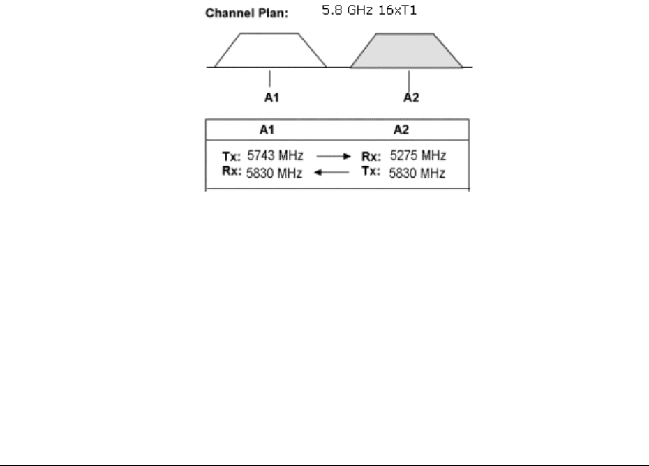
Lynx.GX and Tsunami Wireless Radio Installation and Maintenance
As a rule of thumb, do not place opposite frequency plan radios (such as A1 and A2) at the same site. In
most cases, you should use the same frequency plan (such as A1 and A1) or, in some cases, a different
frequency plan from the same side of the band (such as A1 and B1, when more than one channel plan is
available).
With careful engineering, you can easily place more than one radio of the same frequency channel plan at the
same site. When designing these configurations, antenna size, antenna polarization, and antenna location
are critical.
Using alternate channels (such as A1 and A2) is highly unlikely to be successful (and therefore not
recommended) due to the high level of transmitter-to-receiver isolation required from the antenna system.
Antenna polarization should always be oriented such that ‘adjacent’ links are oppositely polarized relative to
one another (that is, vertically and horizontally). This provides additional discrimination of the received
signals coming into the hub site. If you must place an odd number of links at the same location, ensure that
the largest angle is bounded by the two links of like polarization. Further interference analysis may be
required to ensure these adjacent links will provide adequate separation.
Though external interference conditions are rare when using these radios, when these conditions do occur,
you can often overcome them by exchanging the radios from end-to-end, thereby changing the receive
frequency to the opposite channel at each end. Changing polarization on the antenna system to the
orientation that provides the maximum rejection to the interference is also an extremely effective measure.
The channel plan is illustrated in the following figure.
Figure 2 Channel Plan for 5.8 GHz 16xT1
The radio must have access to a supply of appropriate power, either DC or AC (if the AC adapter option has
been ordered). The unit can be powered from a DC battery system, or from a solar or generator power
plant, usually with battery reserves. Typically, either a ± 24 or ± 48 volt supply is used.
For DC, be sure the cable is of sufficient gauge to carry the necessary current and is less than three (3)
meters (9.75 feet) in length. A minimum gauge of 14 is recommended.
Before you install the radio, plan for the unit’s continuous power consumption needs. You also should plan
for backup power for critical communication circuits. Backup power allows the radios and associated
equipment continuous operation when primary power is interrupted.
Chapter 2. Planning for Installation 2-17
CPN 62140 12/01/02

Lynx.GX and Tsunami Wireless Radio Installation and Maintenance
Planning for Antenna Installation
In general, the larger the antenna used with the radio, the better the link performs. Larger antennas have
narrower beamwidth and higher gain, which yield better link performance (higher fade margin, better
availability) and improve immunity to interference (due to the narrower beamwidths).
However, larger antennas are more costly to purchase and install than smaller antennas and, in some cases,
require special installation equipment and more robust mounting structures (due to increased weight and
wind loading). You should consider all of these factors when selecting an antenna.
Prior to installation, determine the specific antenna location and mounting. The transmission line should be
kept as short as possible, so when line-of-sight placement of antennas allow flexibility, it is always desirable
for the equipment to be located closer to the antenna.
This advanced planning also yields the transmission line requirements.
Note: In areas for which transmitted output power restrictions apply, the use of larger antennas benefit
narrow beamwidths and receive gain. However, you may need to reduce output power to meet
regulations.
Only directional antennas should be used with Lynx radios. These typically are flat-panel or solid
parabolic antennas. Proxim Corporation recommends a minimum 3 dB beamwidth of 10° for
directional systems.
The following tables list antenna types, performance, and manufacturers.
Antenna Manufacturer Information
Antenna Type Manufacturer Model Number Mid-Band Gain (dBi)
1-foot flat panel Gabriel
Andrew
RFS
DFPD1-52
FPA5250D12-N
MA0528-23AN
23.5
23.6
23.0
2-foot flat panel Gabriel
Andrew
RFS
DFPD2-52
FPA5250D24-N
MA0528-28AN
28.0
28.2
28.0
2-foot parabolic Gabriel
Gabriel
Radio Waves
Andrew
RFS
SSP2-52B
HSSP2-52
SP2-5.2
P2F-52
SPF2-52A
28.5
28.1
28.3
29.4
27.9
3-foot parabolic Radio Waves
Andrew
RFS
SP3-5.2
P3F-52
SPF3-52A
31.4
33.4
31,4
4-foot parabolic Gabriel
Gabriel
Andrew
Radio Waves
RFS
RFS
SSP4-52A
HSSP4-52
P4F-52
SP4-52
SPF4-52A
SDF4-52A
34.2
33.9
34.9
34.6
33.9
33.9
Chapter 2. Planning for Installation 2-18
CPN 62140 12/01/02

Lynx.GX and Tsunami Wireless Radio Installation and Maintenance
6-foot parabolic Gabriel
Gabriel
Radio Waves
Andrew
RFS
RFS
SSP6-52A
HSSP6-52
SP6-5.2
P6F-52
SPF6-52A
SDF6-52A
37.5
37.2
37.7
37.6
37.4
37.4
8-foot parabolic Gabriel
Gabriel
SSP8-52A
HSSP8-52
39.8
39.6
Transmission Line
Type Manufacturer Model
Number
Loss/100
(dB) ft.
Notes
½-inch foam coax Andrew LDF 4-50 6.1 Add –0.25 dB per connector
5/8-inch foam coax Andrew LDF 4.5-50 4.7 Add –0.25 dB per connector
Waveguide Andrew EW-52 1.2 Does not include transitions
½-inch foam coax Times Microwave LMR-600 7.3 Add –0.25 dB per connector
5/8-inch foam coax Times Microwave LMR-900 4.9 Add –0.25 dB per connector
Within the USA and Canada, antennas other than those illustrated in these tables can be used with this radio,
but must be of the same type (flat panel or solid parabolic), dimensions, and gain as those listed in the table.
Antennas with gain less than 23.5 dBi are not approved for use within the USA or Canada. Consult
governmental regulations or Proxim Corporation for applications outside of the USA or Canada.
For further information regarding antenna installation and adjustment, see “Installing and Adjusting the
Antenna” on page 25.
The Formula for determining the maximum output power setting for 5.25-5.35 GHz U-NII (LE-LAN)
Transmitters (@ EIRP=30dBm) is:
Max Tx (dBm) is the lesser of 24 dBm and 30 - G + FL
The Formula for determining the maximum output power setting for 5.725-5.825 GHz U-NII (LE-LAN)
Transmitters (@ EIRP=53dBm) is:
Max Tx (dBm) is the lesser of 25 dBm and 53 - G + FL
The Formula for determining the maximum output power setting for 5.725-5.850 GHz Spread Spectrum
Transmitters (@ EIRP=54.5dBm) is:
Max Tx (dBm) is the lesser of 25 dBm and 54.5 - G + FL
(note: EIRP shall never exceed 54.5 dBm. This is for the compliance to the CFR 47 Part 1.1310 for RF
exposure)
Chapter 2. Planning for Installation 2-19
CPN 62140 12/01/02

Lynx.GX and Tsunami Wireless Radio Installation and Maintenance
Reviewing the Installation Process
The following is an overview of the installation process to assist you in your planning activities.
1. Test radios back-to-back and configure
■ Use a minimum of 60 dB and no more than 80 dB attenuation and a short low-loss RF transmission line
to connect the two radios.
■ Apply power.
■ Verify the RF Link LED is not red.
■ Verify configuration settings (through the Web Interface) for proper configurations.
■ Connect to services if possible to verify network connection and configurations.
2. Mount antennas
■ Antenna height can be critical for path clearance and line of sight.
■ Ensure that antennas will not be blocked by people.
■ Antenna structure must be secure for wind load and whatever climbing may be necessary.
3. Run transmission line route and egress, including lightning arrestors
■ Use proper transmission line.
■ Proper termination is critical, especially at 5.8 GHz.
■ Be careful with the bend radius and never kink the transmission line.
■ Secure transmission line to structures; be careful not to crush.
■ A direct connection to the antenna feed is ideal (if required, you can use a flexible jumper at the
antenna, a properly specified 90-degree connector/adaptor, or both).
■ Weatherproof all outdoor connections when completed with installation.
■ RF Lightning arrester is best located at the building egress point when the RF Unit is placed indoors.
■ Three lightning arrestors are recommended when the RF Unit is placed outdoors; one at the RF input
(from the antenna), one at the junction between the RF Unit and the interconnect cable, and one at the
building egress point.
■ All lightning arrestors and transmission line must be properly grounded.
4. Connect radios to antennas and power, including grounding
■ Connect to RF transmission line from antenna directly or using flexible jumper, if necessary.
■ Do not use 90° adapters unless rated at operating frequency.
■ Connect RFU-to-IDU cable.
■ Test power voltages and pinouts before connecting power to IDU.
Chapter 2. Planning for Installation 2-20
CPN 62140 12/01/02

Lynx.GX and Tsunami Wireless Radio Installation and Maintenance
5. Align antennas
■ Rough align antenna azimuth and elevation based upon path planning (using compass bearing or
milestone sighting, telescopic sight, binoculars, and so on).
■ Use a Digital Volt Meter (DVM) or headphones/earpiece/speaker to read the radio’s RSL voltage provided
on the RFU to peak antennas.
º If the RFU is mounted indoors, you may need to temporarily run separate wires from the RSL port to
antenna. Alternatively:
▪ The RSL value can be provided by a ‘verbal relay’ or by two-way radio (or similar
communications device) from the radio location to antenna alignment personnel.
▪ The RFU can be taken to the antenna location temporarily for the purposes of antenna
alignment. An additional short transmission line jumper may be required for this approach,
along with TNC-to-N adaptors at each end of the primary transmission line.
▪ Coaxial couplers can be placed temporarily at each end of the primary transmission line to allow
for the RSL voltage to be sent to the antenna location.
■ Make sure antenna polarization is the same at both ends.
º Adjust alignment of one antenna at a time, one plane (azimuth versus elevation) at a time.
º Adjust each end multiple times until predicted RSL is achieved.
6. Check RSL against predicted results, iterate, and troubleshoot
■ Is the RF Link LED red?
º If so, keep aligning.
º If not (or green), the radios are talking!
■ Does the measured RSL at both ends closely match the predicted value?
º If too strong, probably OK.
º If not strong enough, keep aligning.
º If still not strong enough, double-check the prediction and compare to the actual installation (verify
antenna gains, lengths/type of transmission line, path length, and so on).
º Are you sure you have line of sight?
º Did you test the radios in advance?
º You could have a bad cable, connector termination, or antenna
■ Do you need to adjust the output power down?
º Check path calculations and regulations.
º Re-verify RSL after power is adjusted.
Chapter 2. Planning for Installation 2-21
CPN 62140 12/01/02

Lynx.GX and Tsunami Wireless Radio Installation and Maintenance
7. Troubleshooting
■ Most common problems are poor transmission line connector terminations.
º Best way to test is a return loss measurement (VSWR).
º Basic function can be tested using a continuity and short test with DVM.
º The transmission line can be evaluated with a spectrum analyzer connected to the radio through the
cable and comparing when spectrum analyzer is connected directly to the radio without the cable.
º Transmission line loss can be evaluated with a back-to-back RSL test.
º “Tap and wiggle” testing of all terminations while monitoring RSL and alarms can expose poor
terminations.
■ Could be a faulty antenna.
º Very hard to tell without swapping.
º VSWR test on antenna feed can identify antenna problems.
º “Tap” test can expose a faulty feed for moisture or connector problems.
■ Could be a faulty radio.
º Back-to-back RSL testing normally exposes a faulty radio.
■ Could be a path obstruction.
º Re-evaluate path clearance including Fresnel zone criteria.
8. Connect services and test connectivity
■ Perform a loopback test, a BER test, or both.
■ Connect T1 connections, NMS connections, and so on.
■ Test network connectivity.
■ Double-check line codes and LBOs for all T1 connections.
Helpful Hints
■ Telephones plugged into the Orderwire jack provide verbal communication across the link after the link is
synchronized (very helpful to coordinate alignment and testing).
■ Use the FAR END button to determine status and RSL of the far-end radio for troubleshooting.
■ Keep radios at maximum (factory) power for the alignment phase.
Chapter 2. Planning for Installation 2-22
CPN 62140 12/01/02

Lynx.GX and Tsunami Radio Installation and Configuration
Chapter 3. Installing the Units
Mounting the Units
Assembling Required Materials
The radios are shipped in boxes unless ordered as an integrated system and configured at the factory. In
that case, the equipment may be racked and shipped in a crate. The equipment is packaged so as to prevent
damage in transit.
The following figures illustrate the items required for installation:
3-23
Figure 3 Shipping Container Contents for 2-Piece Radios
In addition to the above installation components, the following items are also included:
■ Terminal block and locking block (for DC power connection)
■ 9-pin D connectors (for mating to the Alarm and IDU CONFIG ports)
■ 8-pin Modular connectors (for mating to the VF, AUX DATA, NMS, T1/E1 traffic ports)
■ Factory test data sheet
■ Publications and Software CD
Save the test data sheet that is provided. The test data sheet can be placed where the Lynx terminal is
installed for future reference. All units are tested individually and the actual measured performance recorded
on the Factory Test Data Sheet. This information should be useful during installation, troubleshooting, and
maintenance. You should have a copy of test data sheets from both ends of the radio link at each radio
location, as well as a copy at the primary radio management center for reference.
Quick installation instructions are also provided at the back page of the Factory Test Data Sheet; this
document can be useful for reference during installation.
The boxes should be left intact and sheltered until arrival at the installation site.
Appendix A
CPN 62140 12/01/02

Lynx.GX and Tsunami Radio Installation and Configuration
If the shipping container shows signs of damage, notify the transportation company immediately. Upon
receipt, inspect contents to make sure no parts are missing or damaged.
You should retain all the packaging materials (including all internal boxes). In the unlikely event that you
must return the equipment to the factory, use the original packing materials for return shipment. The
packaging materials also are recommended for transporting the equipment from location to location.
The following accessories are shipped with your system:
IDU
The shipping container accessory kit includes the following items for IDU bracket mounting:
■ Rack-mounting bracket
■ Bracket screws
■ IF cable for connecting to the RF unit if the RF unit is installed indoors alongside the IDU
RF Unit
The shipping container accessory kit includes the following items for outdoor RF Unit pole mounting:
■ 1/4-inch split lock washers
■ Hex nuts
■ Flat washers
■ Threaded rods
■ Socket head screws
■ Antenna cable
■ Mounting brackets
■ Mounting plate
Required Tools
The following sections list the tools needed when installing the Lynx radios.
IDU Installation Tools
You must obtain the following tools before installing the IDU:
■ Phillips (cross-tip) screwdrivers (for 19-inch rack mounting and attachment of brackets)
■ Small blade standard screwdriver (for power supply connector)
■ Wire strippers (for removing insulation from power supply wiring and other wiring)
■ Wire crimpers (if using any 8-pin modular (RJ-45 and RJ-48C) connectors that are not pre-made)
■ Soldering iron (if using any D-type connector)
Appendix A 3-24
CPN 62140 12/01/02

Lynx.GX and Tsunami Wireless Radio Installation and Maintenance
Outdoor RF Unit Installation Tools
You must obtain the following tools before installing the RFU:
■ Adjustable 6-inch or 8-inch wrench (for installing the RF cable)
■ Weatherproofing material (butyl and electrical tape, butyl tape or self-vulcanizing adhesive) such as
Scotch brand 700 commercial grade Electrical tape (for sealing the IDU, antenna, and RSL connectors)
Test and Configuration Tools
The following tools are necessary or useful to have available for testing and configuring the radios:
■ Digital Voltmeter (to measure RSL, DC power, and so on)
■ RF power meter (to measure transmitter output power)
■ Cellular phone or two-way radio (for talking with far-end crew and tower crew)
■ Bit Error Rate test set (to test link after installation)
■ Computer with Ethernet Network Interface Card, CAT5 cable and Internet browser software (for NMS
access)
■ Pair of touch-tone telephones (to test Orderwire circuits and for communication with far-end)
■ Headphone or audio device with BNC adapter (for antenna alignment)
Additional tools may be needed for antenna and transmission line installation and antenna alignment as well
as the lightning arrestor mounting and grounding. Consult the antenna manufacturer documentation and
review “Installing and Adjusting the Antenna.”
Mounting the Lynx and Tsunami Radio Units
The following sections provide installation procedures:
■ IDU Installation
■ Indoor RF Unit Installation
■ Outdoor RF Unit Installation
There are two primary ways to install the Lynx and Tsunami radio system.
■ The first is the case in which both units (the IDU and the RFU) are mounted indoors or in a suitable
enclosure, stacked on top of one another, in a rack or on a tabletop.
■ The second is the case in which the IDU is mounted indoors and the RFU is mounted outdoors, either
near the antenna or simply at a location somewhere between the enclosure/structure egress point and
the antenna.
Complete installation of all cables and the antenna system prior to connecting power; refer to “Antenna
Installation and Adjustment Guidelines” for important information.
Chapter 3. Installing the Unit 2-25
CPN 62140 12/01/02
Lynx.GX and Tsunami Wireless Radio Installation and Maintenance
Installing the Indoor Unit
Rack mounting of the IDU is the ideal configuration. The Lynx and Tsunami radio alternatively can be placed
on a tabletop or a cabinet shelf. You should secure the radio system with a strap when not mounted directly
to a racking system.
For rack mounting, to avoid interference with the RF unit or antenna cables, you should mount the unit at the
highest space in a standard 19-inch rack. Empty rack-mounting spaces above and below the unit are
recommended, especially if the surrounding equipment dissipates a considerable amount of heat (over 40W).
If you plan to mount the RFU indoors, use the top two rack spaces for the radio system, mounting the IDU
and RFU directly adjacent; leave a minimum of one space above the total 2-unit space for the radio.
Set up the radio for mounting (using the rack mounting brackets enclosed with the screws in the shipping
container) with the front edge projecting from the front face of a standard 19-inch rack. Alternatively, you
can reverse the rack-mounting brackets to install the unit at a flush position.
The radio has internal fans that intake on the left side and exhaust on the right side of the chassis. When
rack mounting, leave a small gap between the outer edges of the radio and the inside edge of the rack.
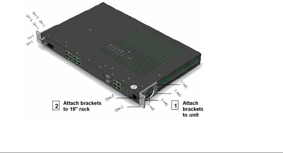
To rack-mount the IDU:
1. Set the unit on a flat surface and, using a screwdriver, remove the front screws on each side of the unit.
You must remove these screws to prepare the unit for bracket attachment.
2. Attach a mounting bracket to each side of the unit using the long mounting screws that are provided in
the IDU accessory kit.
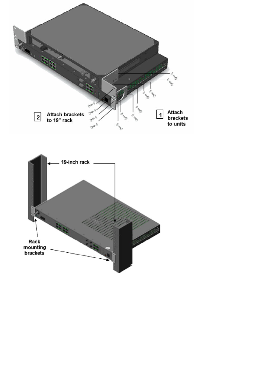
The following figures illustrate mounting bracket attachment for the IDU only (occupying one space in a
19-inch rack) and for the combined IDU and RFU (occupying two spaces in a 19-inch rack).
Chapter 3. Installing the Unit 2-26
CPN 62140 12/01/02
Lynx.GX and Tsunami Wireless Radio Installation and Maintenance
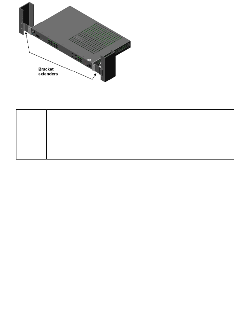
3. Position the radio in the rack and align the holes in the mounting bracket with the holes in the rack.
If you are installing the IDU in a 23-inch rack, you must attach extenders to the rack mounting brackets,
as shown in the following figure:
Chapter 3. Installing the Unit 2-27
CPN 62140 12/01/02
Lynx.GX and Tsunami Wireless Radio Installation and Maintenance
4. Insert two bolts and lock washers, appropriate for your 19-inch rack, into each of the mounting brackets
and tighten.
Important: When the RFU is rack mounted, it must be mounted directly above the IDU and facing
with the connectors forward in the same direction as the front panel of the IDU (as
shown).
The IDU fan exhaust is used to cool the RFU in a rack mount configuration. Also, if one
unit is projection mounted, both units should be projection mounted. In either
configuration, an empty rack mount space is required above and below the configuration.
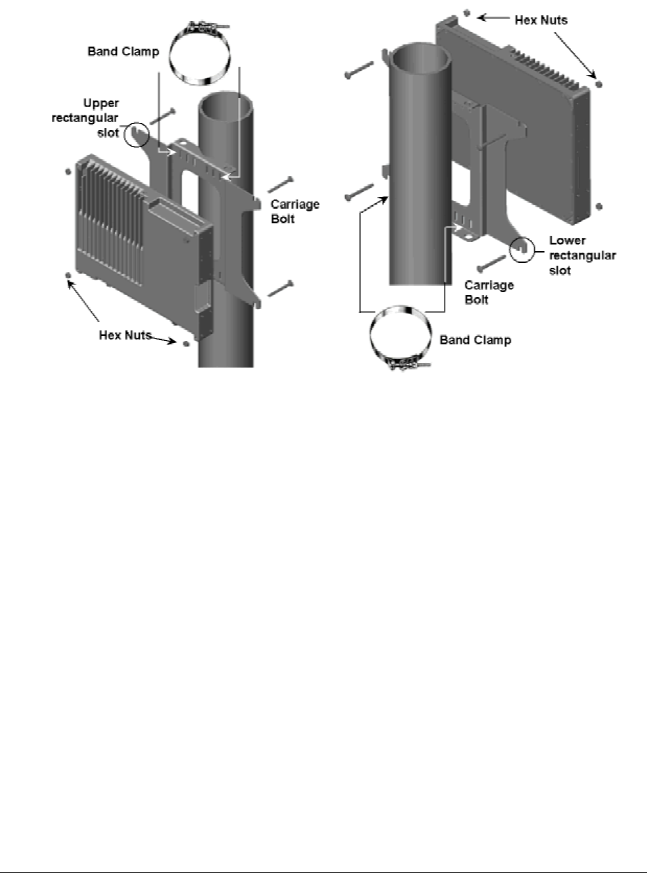
Installing the RF Unit in an Outdoor Configuration
The outdoor RFU installation is a two-step procedure:
■ Install the mounting bracket and plate onto the pole. Use two band clamps (not included).
■ Mount and secure the RFU on the mounting plate.
To install the RFU, follow these steps:
1. Hold the mounting plate with the upper and lower V-cut tabs in contact with the pole.
Chapter 3. Installing the Unit 2-28
CPN 62140 12/01/02
Lynx.GX and Tsunami Wireless Radio Installation and Maintenance
2. Wrap band clamp around pole/mast and through the vertical slots near the top of the mounting plate.
Repeat for lower slots.
3. Tighten both band clamps sufficiently to prevent the mounting plate from rotating on the pole/mast; you
are now ready to mount the RF unit onto the bracket assembly.
4. Orient the RFU for mounting onto the mounting plate so that the connectors are pointed down and the
heatsink fins are facing away from the bracket.
5. Insert carriage bolts into the upper holes. Place both thumbs over the hex nuts; place the RFU onto the
mounting plate by setting the square portion of the carriage bolts into the upper, rectangular slots on the
mounting plate. Loosely attach the self-locking hex nuts.
6. Insert carriage bolts into the lower holes. Loosely attach the self-locking hex nuts.
7. Tighten all hex nuts sufficiently to prevent the RF U from any movement. Ensure the heads of the
carriage bolts are firmly against the mounting plate prior to tightening the self-locking hex nuts.
8. Install the RF lightning arrestor that connects to the antenna cable to the RFU Type-N connector labeled
To Antenna and seal the connectors using weatherproofing material (butyl and electrical tape, butyl
tape or self-vulcanizing adhesive) listed in “Installation Requirements.”
9. Install the IF/DC-passing lightning arrestor that connects to the IDU cable to the RFU TNC connector
labeled To IDU and seal the connectors using weatherproofing material.
Chapter 3. Installing the Unit 2-29
CPN 62140 12/01/02

Lynx.GX and Tsunami Wireless Radio Installation and Maintenance
Installing and Adjusting the Antenna
The installation information discussed in this section is generic. For installation procedures specific to the
antenna you are installing, refer to the antenna manufacturer’s documentation.
Antenna Installation
WARNING (FCC requirement for implementation in the USA):
Antennas used for the transmitter must be fix-mounted on outdoor permanent structures with a
separation distance of at least 1.5 meters from all persons during normal operation. Antennas
must be professionally installed. Installers must be provided with antenna installation
instructions and transmitter operating conditions, including antenna co-location requirements of
CFR47 Part 1.1307(b)(3), for satisfying RF exposure compliance.
Antenna installation consists of permanently mounting the antenna to the mast, pole, or tower and then
attaching the RFU to it.
The antenna and RFU assembly must be mounted outdoors on a tower, building roof, or other location that
provides line-of-sight path clearance to the far-end location. In some cases, the antenna can be mounted
indoors, behind a window. However, RF attenuation through windows can vary greatly, depending upon the
glass and any coatings that might be present, plus the precise location and angle of the antenna relative to
the window. In cases of indoor installations, ensure that the antenna location is restricted and bear in mind
the RF exposure requirements of the warning statement above.
In general, antennas smaller than 2.0 feet diameter, or 1-foot panels, are not recommended for use with
these radios.
Antennas should be:
■ Ordered with the suitable mounting kit specific to the site requirements.
■ Very rigidly mounted, with adequate room for azimuth and elevation adjustment from the rear.
The antenna polarization must be the same at both ends of the link, either vertical or horizontal.
In general, antenna mountings require a support pipe to which upper and lower support brackets are
attached with U-bolts. The antenna and optional elevation and azimuth adjustment rods are then mounted
onto the support brackets. The entire structure must be adequately grounded for lightning protection. The
antenna system must always be installed according to the manufacturer's instructions.
Unless special test equipment is available, two operating Lynx radios are required to align the antennas.
Alternatively, you can use a CW generator to transmit a signal toward the end being aligned.
The antenna is coarse-aligned using visual sighting and then fine-aligned using the receive signal level (RSL)
voltage of the radio.
The RSL voltage reading still can be used to peak antennas even if the wireless units have not synchronized;
however, you cannot measure far-end RSL from the near-end terminal until the units are synchronized.
Chapter 3. Installing the Unit 2-30
CPN 62140 12/01/02

Lynx.GX and Tsunami Wireless Radio Installation and Maintenance
Alignment Guidelines
When aligning antennas, if the RFU is located indoors or distant from the antenna location, you may want to
run wires or a cable from the RSL test point to the antenna so that the voltmeter reading or audio device is
directly visible and audible to the technicians aligning the antenna. Alternatively, you can use coaxial
couplers to couple the RSL voltage from an IDU to bring the voltage to the antenna location. If this approach
is used, remove couplers after alignment is complete. You may also temporarily mount the RFU near the
antenna for the purposes of alignment (an additional short RF transmission line may be required).
A cellular telephone or two-way radio can be useful for coordinating alignment activities between both ends
of the link. Once you have coarse-aligned and synchronized the units, you also can use the built-in order
wire phone service to coordinate installation.
An order wire telephone can provide end-to-end voice communications once the units are synchronized.
Synchronization usually can be accomplished by coarse alignment alone. After synchronization, you can use
the orderwire phones to communicate between radio sites for antenna fine alignment activities. The phone
interconnect cable can be extended to the antenna when desired.
The larger the antenna size, the more critical alignment becomes. For example, with a 2-foot dish at 5.8 GHz,
the antenna can be moved ±3 degrees off the correct heading before the receive signal level drops by 3 dB.
This compares with a 6-foot dish, which may only be moved ±1 degree for the same degradation.
■ It is critical that antenna alignment be performed on one end of the link at a time, one plane at a time.
■ One antenna should remain stationary at all times.
■ Each end should be fine-aligned several times, until the planned RSL is reached.
In some cases, you may need to perform coarse alignment using a wide arc in both azimuth and elevation
while reading the RSL to find the main beam of the opposite end antenna.
Note: The RSL voltage is slightly delayed, so make small incremental adjustments during the fine
alignment phase and wait for the RSL voltage to settle at each adjustment. When aligned to
maximum RSL, ensure that all antenna mechanics are tightened without impacting the alignment.
Coarse Alignment
To coarse-align the antenna, set the antenna for flat elevation (no up-tilt or down-tilt) using a spirit level;
point the antenna at a heading marker obtained using a compass/GPS (magnetic corrected) back-bearing
from an adjacent location (ideally, 100 feet or more away from the antenna). If the path has substantial
change to elevation from one end to the other, this may not be an advisable method for starting the
alignment activities. In such cases, compare antenna elevations at each end of the link and set the initial
elevation of the antenna to roughly match the anticipated up-tilt or down-tilt.
If you cannot set a heading marker sufficiently far away (for example when on a city building roof or looking
through a window), obtain a rough azimuth setting by sighting along the antenna feed or based upon
compass measurements made during the path planning stage.
Chapter 3. Installing the Unit 2-31
CPN 62140 12/01/02
Lynx.GX and Tsunami Wireless Radio Installation and Maintenance
Note: Use the instructions provided by the antenna manufacturer to verify that both antennas are on
the same polarization; otherwise, the RSL will be approximately 25 to 30 dB below the calculated
level.
Because maximizing the receive RF signal level at each end of the radio link is critical, most antennas also
require fine alignment using an operating link.
Once the coarse alignment is completed at both ends, the link can be powered and some level of reliable
communication established. The voltage at the Lynx test point can be measured with a DVM to determine
the relative receive RF signal level.
Note: Make sure that you read Power Connections prior to powering up the Lynx radios.
Fine Alignment
When fine-aligning the antenna:
■ Adjust the azimuth and then the elevation of the local antenna to maximize the RSL voltage.
■ Align the far-end antenna in the same manner, using the RSL voltage of its local RFU.
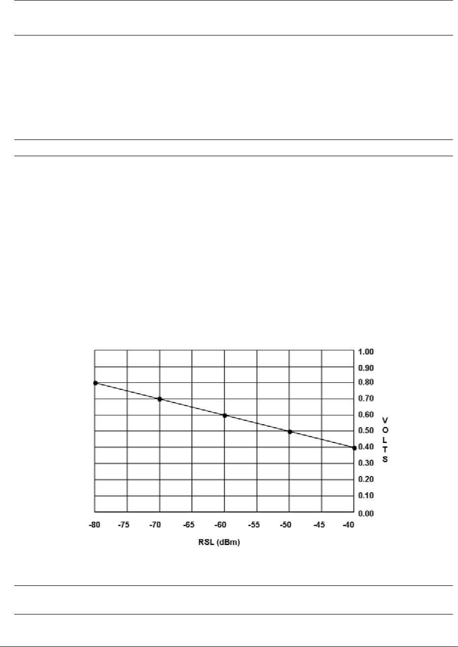
RSL Voltage Guidelines
The following example graph illustrates the typical variation of RSL voltage as the receive signal level is
increased from threshold to a higher level. There is some variation between receivers, but an approximate
estimate of the potential RSL value can be made using this figure.
12/
Figure 4 Typical RSL Voltage vs. Receive RSL
Note: Use the Factory Test Data Sheet shipped with your terminal to obtain the best estimate of your
RSL.
Chapter 3. Installing the Unit 2-32
CPN 62140 01/02

Lynx.GX and Tsunami Wireless Radio Installation and Maintenance
Above -30 dBm RSL, the receiver can produce errors; however this level is rarely exceeded. Refer to
Calculating Received Signal Level and Link Budget to calculate the anticipated RSL.
During anomalous propagation conditions, the RSL can fade up but does not typically increase by more than
10 dB (except in unusual, very long paths, which may increase by 15 dB).
Antenna alignment should enable the RSL to peak to the level calculated in the link budget. If the RSL is
peaked but is approximately 20 dB below the calculated level, it is likely the antennas are aligned on a
sidelobe of the antenna's radiated signal. In such case, you must adjust the antennas in a wide arc in both
azimuth and elevation (at both sides) until the main lobe is located.
Other typical causes of low RSL are:
■ Path obstructions
■ Excess loss in connectors/cables (poor terminations, improper bend radius, kinked, crushed, and so on)
■ Poor quality or unaccounted for adapters and pigtail jumper cables
■ Different antenna polarization at each end of the link
■ Misadjustment of the radio’s transmit power output adjustment
■ Insufficient RF output power (faulty radio transmitter)
■ Faulty antenna
Establishing Connections
Antenna Connection
The Lynx radio is equipped with an N-type female connector at the antenna port. You can use a short length
jumper cable (such as 1/4-inch to 1/2-inch coax or pigtail of approximately 6 feet in length) fitted with two
N-type male connectors to connect the antenna port to the antenna (if the RFU is located near the antenna)
or to the primary transmission line (if the RFU is mounted remotely from the antenna).
A low-loss 50-ohm cable is recommended for the antenna transmission line between the RFU and the
antenna (such as Andrew LDF4-50 or Times LMR-600 1/2-inch coaxial cable, an Andrew LDF4.5-50 or Times
LMR-900 5/8-inch coaxial cable, or an EW-52 waveguide).
The return loss presented by the transmission line at the RFU interface should be as high as possible (20 dB
minimum recommended). The length of the antenna transmission line should be kept as short as possible to
minimize losses.
To minimize feeder losses, use an elliptical wave guide (typical loss is 1.25 dB/100 ft. at 5.8 GHz) for
implementations with longer transmission line lengths (such as >200 feet) or long paths (such as >20 miles).
Depending upon path length and transmission line feeder length, ½-inch or 5/8-inch coaxial cables are often
sufficient.
Chapter 3. Installing the Unit 2-33
CPN 62140 12/01/02

Lynx.GX and Tsunami Wireless Radio Installation and Maintenance
Antenna Cabling Guidelines for 5.8 GHz Units
■ Coaxial cables of 7/8-inch or larger diameter can exhibit moding at 5.8 GHz and are never recommended.
Also, some small diameter cable types, such as RG-8, will have high loss or poor VSWR at these
frequencies. If small diameter cables are required, be certain to keep the lengths of these cables as short
as possible.
■ For wave guide transmission line at 5.8 GHz, EW-52 wave guide is recommended. EW-63 will also work,
but may exhibit more loss.
■ Do not use right angle N-type connectors with the Lynx radios operating at 5.8 GHz unless the connector
has been specifically rated and tested up to 5850 MHz. Unless specifically designed for these
frequencies, these connectors may present high loss at these frequencies.
■ Do not use a low quality jumper cables with the radios.
■ Always precisely follow manufacturer’s recommended procedures and tools for termination.
Transmission Line Connection
If the RFU is mounted near the antenna, the RF transmission line can be pre-terminated at both ends and
simply attached from the antenna feed to the RFU without any special consideration to securing the
transmission line to the antenna structure (as the length is likely to be very short).
In this configuration, Proxim recommends you place an RF lightning suppression device specified for use at
5.8 GHz (such as Polyphaser LSX) between the RF transmission line and the RFU’s RF port, as close as
possible to the RFU. Always properly ground any lightning suppression device.
When the RFU is mounted near the antenna, generally follow the following instructions for the cable that is
used to connect the RFU to the IDU. This cable is likely to be longer and will also egress the structure in
which the IDU is located. It may require more care for installation, including grounding and securing the
cable.
Lightning suppression is required at the interconnection cable junction as close as possible to the RFU, as well
as at the egress point. For this cable, the lightning suppressors must be designed to pass DC and support
the intermediate frequencies (approximately 800 MHz) and the digital signals carried by this cable.
Polyphaser carries an appropriate device for this application.
To prepare the transmission line feeder or the RFU-to-IDU cable:
1. Cut the cable to the approximate length (allowing some excess).
2. Install the appropriate connector on the antenna or RF Unit end:
Place tape or a covering over the connector end so that debris cannot harm the connector.
Pull the transmission line through the cable ducts, trays, or conduit (as required) to the antenna, while
being careful not to kink or damage the transmission line in any way.
Chapter 3. Installing the Unit 2-34
CPN 62140 12/01/02

Lynx.GX and Tsunami Wireless Radio Installation and Maintenance
RF transmission line must never be bent, twisted, or deformed in any way.
Pay close attention to the transmission line specifications for bend radius when installing.
3. Support the transmission line in a tray on horizontal runs and by hangers on vertical runs. Space
hangers according to the manufacturer instructions (typically every five feet under conditions of no ice
and not greater than 85 mph winds).
4. Ground the transmission line using the manufacturer grounding kit. Grounding kits attach to the outer
copper conductor. Install grounds at the antenna, at the bottom of the antenna structure (if applicable),
and where the transmission line enters the building. Be sure to ground long transmission line runs
every 100 feet.
5. Install lightning protection devices, including proper grounding and termination to cables. There should
always be a lightning protection device at the egress point for whatever cables egress the building or
enclosure.
For an all-indoor implementation, the in-line lightning protection device must be rated for the operating
frequency of the Lynx (5.8 GHz).
Lightning protection for the RFU-to-IDU connection portion of an outdoor implementation of the RFU
must be rated to 800 MHz and must be non-blocking to DC. Proxim recommends placing lightning
arrestors near the RFU and at the egress point for 2-piece systems. Lightning arrestors must be
properly grounded to operate.
6. After installation, terminate the transmission line with an N-type male connector or adapter attached at
the equipment end. For wave guide, this typically requires a CPR-to-N adapter.
Be sure to use manufacturer-specified connectors and termination tools, and follow termination
instructions precisely. Improper transmission line terminations can cause excess losses and reflections
that can lead to many problems with the system.
7. Prior to operation, check the electrical integrity of the transmission line, including all connectors, with a
simple DC check between the center conductor and outer conductor (this is neither possible, nor required
for wave guide).
The transmission line ideally should be connected directly to the antenna at one end and to the Lynx
antenna port at the other end (through the RF Lightning arrestor). However, short pigtail jumper cables
may be required to avoid sharp bends in the primary transmission line to limit stress on either
connection.
Chapter 3. Installing the Unit 2-35
CPN 62140 12/01/02
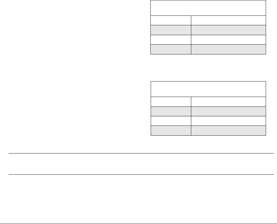
Lynx.GX and Tsunami Wireless Radio Installation and Maintenance
Power Connections
The following sections describe the wiring and power connections for the Lynx radios.
The Lynx radios do not have a power on/off switch. When you connect the DC power, the unit powers up
and is operational immediately. There can be up to 200mW of RF power present at the antenna port. The
antenna port should be terminated (either connected to an antenna or an appropriate 50-ohm load, such as
provided by a fixed RF attenuator) before power is applied. Connect the cable between the IDU and the RFU
prior to applying power. The IDU can be powered separately (with no cable or RFU present), but do not
connect the RFU without removing power first; then connect the cable and re-apply power.
Power is connected using the terminal block contained in the accessory kit. The terminal connector is a 3-pin
mating connector.
Use the pin information listed in following tables, along with the associated figures, to wire the terminal and
connect the DC power supply properly.
For DC power return connection, connect to the opposite voltage (either the -DC or the +DC Pin) and connect
the return to ground at the DC power plug on pin 2.
Necessary ONLY if power supply needs to be
referenced to chassis ground.
Negative DC Power Input Pin Assignment
(-20 to -63 VDC)
Pin Number Function
1 Power (–DC)
2 Power (–DC)
3 Ground
Figure 5 Negative Voltage DC Connection
Necessary ONLY if power supply needs to be
referenced to chassis ground.
Positive DC Power Input Pin Assignment
(+20 to +63 VDC)
Pin Number Function
1 Return (–DC)
2 Return (–DC)
3 Ground
Figure 6 Positive Voltage DC Connection
Note: Each Lynx terminal block must be fused externally with an 8 Amp maximum fuse. The DC power
cable must be shorter than 3 meters (9.75 feet).
Chapter 3. Installing the Unit 2-36
CPN 62140 12/01/02
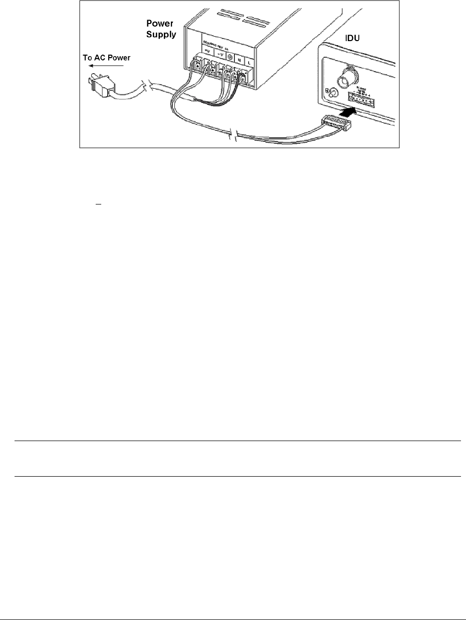
Lynx.GX and Tsunami Wireless Radio Installation and Maintenance
To wire the DC power, wire the power cable with an adequate current rating (minimum 18 AWG) into the
terminal block using the screw connections on the terminal block.
Figure 7 Power Connection for IDU
The recommended minimum current rating of external fuses and cables is 5 amps. The Lynx radios consume
less than 3.1 Amp + 48V.
■ If using negative power, connect the negative voltage to pin 1. Connect the ground return connection
to pin 3 and use an optional jumper to pin 2 for ground reference.
■ If using positive power, connect the positive voltage to pin 3. Connect the ground return connection to
pin 1 and use an optional jumper to pin 2 for ground reference.
The ground connection is available using pin 2. Do not ground both sides of the power supply.
Proxim recommends you leave the ground connection floating if the power supply also is floating. This
configuration can help avoid ground loops and provide the best lightning protection; however, if the power
source is referenced to ground, this configuration may not provide adequate grounding for lightning
protection. This configuration is more susceptible to lightning damage no matter what grounding scheme for
the radio power supply is chosen.
A grounding screw and nut is provided on the left front panel of the IDU. Be sure to use the local electrical
code to determine wire size and proper connection to the grounding screw.
Note: Proper grounding, either through the chassis or the power supply, is important for protecting the
unit against lightning. A grounding screw hole is provided on the front panel.
After wiring the terminal block for power connection, use a digital voltmeter (DVM) to verify voltage and
polarity of the plug.
Chapter 3. Installing the Unit 2-37
CPN 62140 12/01/02

Lynx.GX and Tsunami Wireless Radio Installation and Maintenance
CAUTION!
Do not connect the DC power plug to the terminal until the RFU is connected to the IDU and
the antenna, or appropriate termination.
Do not connect the RFU-to-IDU cable while power is applied to the IDU. The IDU can be
powered without the RFU connected; however, power should be removed before the RFU is
connected and reapplied after the cable is connected and the RFU is properly terminated at
the RF port.
Adjusting Output Power
In certain cases, you may need to adjust the output power lower from the factory setting; for example, to:
■ Meet EIRP (Effective Isotropic Radiated Power) limits
■ Avoid exceeding the maximum far-end RSL of -30 dBm
■ Coordinate a hub or repeater location
Note: In certain countries, Effective Isotropic Radiated Power (EIRP) limits dictate the maximum output
power the Lynx radio can transmit, given transmission line loss and antenna gain. Consult with
appropriate government agencies or Proxim Corporation if there is any question regarding
maximum output power allowed. Never adjust power above the factory default settings.
Using the NMS port, you can adjust the output power from factory settings.
Note: For precise measurement of transmitter power, a calibrated RF power meter (such as the HP 435B
with Power Sensor HP8481) is recommended. This power sensor can be connected directly to the
output of the radio without exceeding the power rating. With some power meters, it may be
necessary to place a calibrated in-line fixed attenuator between the radio antenna port and the
power meter so as to not exceed the power meter's maximum input level. Thruline power meters
do not operate at Lynx RF frequencies.
If adjusting the output power to meet an EIRP limit, you must calculate the overall system gains and losses,
including feeder losses for the type of transmission line installed and the antenna gain.
You can determine the radio transmit power for EIRP limited installations using the following equation:
Tx Power (dBm) = EIRP Limit (dBm) + Transmission System Losses (dB) - Antenna Gain (dB)
Establishing a Connection Between the Units
Follow these steps to establish connection between the radios:
1. Ensure that the antennas at both ends are aligned.
Perform a general alignment of the antennas on both ends of the path using binoculars, compass, or
other related tools. You must have the antennas aligned as accurately as possible before putting radio
Chapter 3. Installing the Unit 2-38
CPN 62140 12/01/02

Lynx.GX and Tsunami Wireless Radio Installation and Maintenance
traffic over the link. This helps in getting the system running more rapidly. Assure that both antennas
are set for the same polarization (vertical or horizontal at both ends).
2. Connect the transmission line to the antenna and feed it to the Lynx radio location.
Connect the opposite end of the transmission line to the N-type female connector located on the RFU
through a lightning arrestor. If the RFU is mounted indoors or in a shelter, the lightning protection
should be located at the cable egress point. If the RFU is mounted outdoors, it can be mounted at the
RF input port of the RFU. The transmission line connection must be terminated into an antenna or a load
before DC power is applied to the radio.
3. Connect RFU to IDU.
Connect the cable the runs from the RFU to the IDU. If the RFU is mounted outdoors, ensure that proper
lightning protection is used at the shelter or building egress point as well as at the RFU connector.
4. Confirm DC power connection.
With the DC power source active but not plugged into the Lynx radio, confirm with a voltmeter that the
DC mating connector has the proper power connections as discussed in Power Connections.
– Verify the polarity and the absolute voltage on all pins.
– Verify ground connection for power (if applicable).
– Ensure that the RF Antenna port connection is properly terminated before applying power.
5. Connect power to the Lynx radio.
When the unit is initially powered-on, some alarm conditions may be present. This is normal and alarms
can be ignored at this time.
6. Adjust RF power (if necessary).
Using the NMS port, verify the RF output power setting and, if necessary, adjust the output power of the
local transmitter in accordance with the path analysis calculations.
In cases of no EIRP limits, the radio transmitter output power should be left at the factory setting, except
for very short paths using very high gain antennas, where excessive power may not be advised (in which
case power should be reduced).
Terminate the RF output port at all times when power is applied to the Lynx radio. Therefore, disconnect
power to the unit before connecting a power meter; reapply power once connected.
Often, an RF power meter has a limit to the input power it can measure without damage. Proxim advises
you place a calibrated fixed value RF attenuator (typically 20 dB or more) between the Lynx radio and
the power meter to ensure proper operation and safety for the RF power meter. The value of this fixed
Chapter 3. Installing the Unit 2-39
CPN 62140 12/01/02

Lynx.GX and Tsunami Wireless Radio Installation and Maintenance
attenuation then can be added to the value of the RF power meter reading to obtain the actual
transmitter output power.
7. Confirm Received Signal Level (RSL).
Connect a voltmeter to the RSL measurement port on the RF Unit. This voltage reading corresponds to
the Received Signal Level (RSL) of the near-end radio. RSL is the amount of signal the near-end radio is
receiving from the far-end radio. Because the antennas have not been finely aligned, the RSL value at
this time will not be very high. However, you can verify that some communication is taking place
between the two units.
Use the RSL voltage reading to align the antennas. Align one antenna at a time as discussed in
“Alignment Guidelines” on page 31. Align both ends of the link before proceeding.
The RSL voltage output on the unit’s front panel puts out a voltage over the usable range of the unit.
The RSL of both sides of the link can also be measured using the NMS port.
Several factors can contribute to low RSL:
º Incorrect antenna alignment (aligned on a sidelobe and not on the main signal)
º Improper polarization orientation of antennas (horizontal versus vertical)
º Transmission line problems (loose connections, bent or damaged cables, “loss-y” adapters, improper
termination)
º Path obstructions (trees, buildings, hills, and so on)
º Path clearance (line-of-sight, earth curvature, Fresnel zone, diffraction, and partial obstruction)
º Weather (inversion layers, ducting, and multipath)
º Antenna feed (coaxial/connector) problem
º Highly reflective surfaces of the path terrain
If RSL is lower than anticipated, re-check the path clearance and transmission line, as these are the
typical causes of low RSL.
You can verify radio operations by connecting units back-to-back with attenuators (60-80 dB), as
described in “Back-to-Back Testing” on page 58. If the problem persists, see “Troubleshooting” on page
49.
The transmitter output power adjustment on the radio affects the RSL. Depending upon EIRP limits (if
any), path distance, and antenna gain, you may need to adjust the output transmit power to the proper
level before putting the units in service.
Chapter 3. Installing the Unit 2-40
CPN 62140 12/01/02
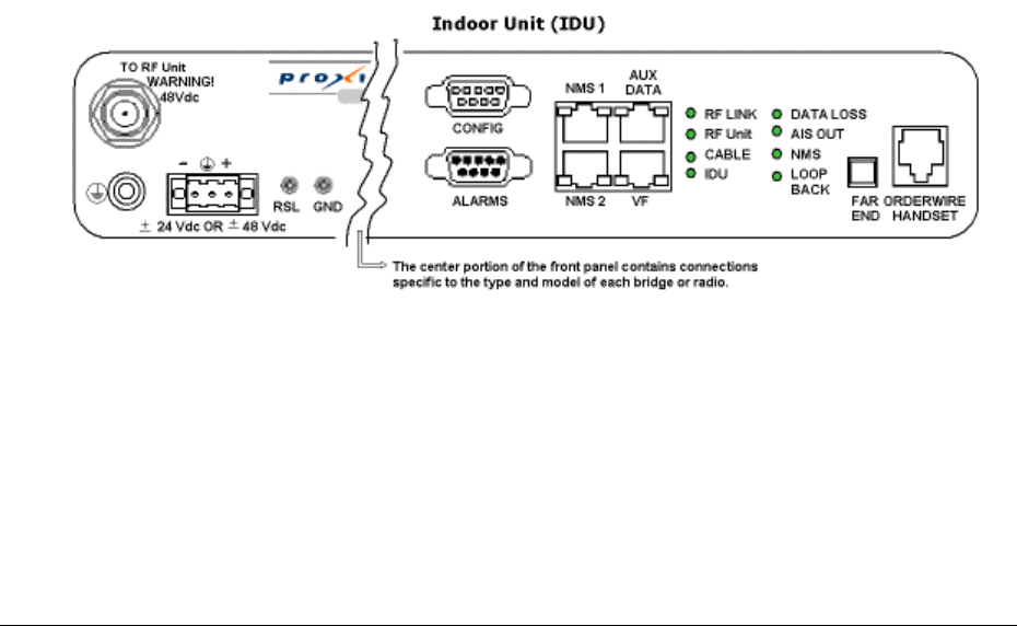
Lynx.GX and Tsunami Wireless Radio Installation and Maintenance
8. Verify the channel plans.
Verify that the units follow the same channel plan and that the opposite Tx and Rx frequencies complete
a matched pair of radios (for example, A1 and A2 make up a matched pair).
9. Connect the unit to the intended telecommunications equipment to pass the T1 traffic.
Connect to the T1 circuits using 8-pin modular (RJ-48C) connectors. All front panel LEDs should either
be off or green. If any LEDs are red, see “LED and Control Button Descriptions” on page 42 or
“Troubleshooting Alarms” on page 55.
Viewing the Radio Front Panel
This section describes the front panel components, LEDs, and control buttons for the Lynx.GX .
The IDU front panel can be thought of as having three distinct parts.
■ The left portion of the IDU contains the connection for the RF Unit, the DC power connection, and the
RSL and GND test points.
■ The middle portion of the IDU contains connectors specific to the Lynx 16T model.
■ The right portion contains LEDs, CONFIG, ALARMS, and ORDERWIRE connections, and a FAR END toggle
switch.
Figure 8 illustrates the left and right portions of the IDU, which are the same for all Lynx.GX models. The
front panel components shown in this figure are described following the figure.
Figure 8 IDU Front Panel
Chapter 3. Installing the Unit 2-41
CPN 62140 12/01/02

Lynx.GX and Tsunami Wireless Radio Installation and Maintenance
Control Button and LED Descriptions
Control Button Descriptions
To RFU
This is an RF TNC female connector that is an integral part of the system. The TNC connector is used to
connect the IDU to the RF Unit.
The voltage on this connector is 42 VDC.
± 24 VDC OR ±48 VDC
The power receptacle recommendation for positive or negative DC power is 24 or 48. However, it will
accept any voltage between 20 and 63 Volts. Optionally, you can use an AC power adapter. For
additional information, see “Power Connections” on page 36.
RSL / GND
There are two front panel test points. Connecting a voltmeter across the GND and RSL front panel test
points, the voltage reading corresponds to the Received Signal Level (RSL) of the near-end radio. For
example, a value of .65V corresponds to –65 dB. Pressing and holding the FAR END button while
measuring the voltage at these test points displays the RSL of the far-end radio.
CONFIG
This is a serial interface port (RS-232) to the radio using a Female DB-9 connector. This port provides
connection to a computer or terminal using a standard null-modem cable for retrieving diagnostic
information, and allows IP and SNMP Community String configuration for the radio. The settings for this
port are 9600 bps, 8 data bits, No Parity, 1 Stop Bit, and No Flow Control. The terminal emulation is
VT100. See “Appendix B. Connectors and Pin Assignments” on page 63 for ALARM port connector
information.
ALARMS
This connector provides alarms for external alarm collection systems using a Male DB-9 connector. There
are two Form C relays that can be connected to other transmission equipment for monitoring alarm status
locally or remotely. One alarm represents Major alarms (usually alarm conditions) and the other Minor
alarms (usually warning conditions). See “Appendix B. Connectors and Pin Assignments” on page 63 for
ALARM port connector information.
NMS1 and NMS2
There are two Ethernet 10/100 Base-TX connections for access to the Network Management System
(NMS) using SNMP, HTTP, or Telnet. Both of these connections auto-negotiate speed and duplex, and
auto-sense MDI or MDI-X connections.
AUX DATA
This is a serial interface port (RS-232) using an RJ-45 connector, which supports speeds from 2400 to
19200 baud (set through the NMS). This allows auxiliary serial data connection from one end of the
Chapter 3. Installing the Unit 2-42
CPN 62140 12/01/02

Lynx.GX and Tsunami Wireless Radio Installation and Maintenance
wireless link to the other. It can be used for separate data connections for serial devices. See “Appendix
B. Connectors and Pin Assignments” on page 63 for AUX DATA port connector information.
VF
This RJ-45 connector is used to link two Lynx radios at a repeater site for Orderwire operation. This allows
Orderwire calls to and from any point in the network. The circuit is a 4-wire audio (2xTX and 2xRX) that
also can be connected to other existing Orderwire networks. All phones off hook hear and participate in
the call. See “Appendix B. Connectors and Pin Assignments” on page 63 for VF port connector
information.
LED Descriptions
LED Descriptions
LED Color Description
RF Link Green
Yellow
Red
Flashing Red
Error-free operation
Bit errors occurring
Excessive bit errors or radio link failure
Link Security ID mismatch within the last minute
RF Unit Green
Yellow
Red
RF UNIT OK
RF UNIT warning
RF UNIT alarm
Cable Green
Red
Cable between system board and RF UNIT is OK
Cable short longer than 5 seconds detected in the last minute
IDU Green
Yellow
Red
IDU OK
IDU warning
IDU alarm
T1 INPUT
(listed by
priority)
Red
Yellow
Green
Off
T1 Input Alarm enabled; T1 data not present on at least one channel
T1 Input Alarm disabled; T1 data present on at least one channel
T1 Input Alarm enabled; T1 data present on at least one channel
T1 Input Alarm disabled; T1 data not present on all channels
AIS OUT Off
Yellow
Not injecting all 1s in data stream upon RF Link Red alarm
Injecting AIS in data stream upon RF Link Red alarm
NMS Green
Off
Tx or Rx NMS data present on the interface
No NMS interface connection detected or no data present
LOOPBACK Flashing Yellow
Solid Yellow
Off
At least one data channel in loopback
Internal loopback has detected at least one error
No loopbacks on any channels
FAR END
When the LED on this button is red, alarms exist on the far-end radio. Press and hold the button to view
those alarms on this radio’s front panel. If the far-end radio is not available, all LEDs flash red. Pressing
and holding this button while powering on the radio resets the IP address settings and passwords to
default values.
Chapter 3. Installing the Unit 2-43
CPN 62140 12/01/02

Lynx.GX and Tsunami Wireless Radio Installation and Maintenance
ORDERWIRE HANDSET
This connection is used to access the electronic orderwire function (a facility for telephone style service
from one radio to another). A standard analog telephone (with an electronic ringer) plugs into this
connector. You can dial the orderwire address of the far-end radio (or any radio in the network) to cause
that radio and any connected orderwire phone to ring; however, communications is automatically
established when both handsets are lifted off hook. This communication does not interrupt or interfere
with the other radio communications. The radio link must be operational to use this facility. The orderwire
feature can be very useful for installation, maintenance, and troubleshooting.
Note: All Lynx radios connected to the same orderwire network should have unique address settings
(telephone numbers).
Establishing Near-End to Far-End Communications using Orderwire
To establish near-end to far-end communications using orderwire:
1. Connect the telephone to the near-end and far-end radios.
Using a standard RJ-11 telephone cable, connect a standard electronic telephone (a touch tone phone,
complete with dialer) to the Orderwire connector on the radio front panel. This connector is wired
identically to a standard two-wire telephone jack. For connector pin assignment, see “Appendix B.
Connectors and Pin Assignments” on page 63.
2. Call the far-end radio.
With a telephone connected to each radio on opposite ends of the link, either telephone can be used to
dial-up the far-end location. The far-end radio internal ringer and the connected telephone ring, and if
answered, two-way full-duplex voice communication is established.
If the radios are connected in a repeater configuration, you can establish Orderwire services in the network
by connecting the radios (by cabling their front-panel VF connectors).
Orderwire operates on radios at each end of the repeater and at the repeater site. You can extend this
function through several repeater sites. For hub connections of three or more Lynx radios, an external 4-wire
radio is required to connect all devices for Orderwire operations.
Dialing an * [asterisk/star key] on the orderwire telephone implements an “all call” feature that rings all
connected radios. All telephones provide communication to all other telephones in the connected network.
Even if a particular telephone does not ring, it can still be used to talk and listen to any ongoing orderwire
activity if the orderwire is in use at other terminal locations.
Also, if a phone anywhere in the connected network has accidentally been left off-hook, the # [pound] key
can be used to mute all off-hook handsets until they are placed on and off hook again.
Chapter 3. Installing the Unit 2-44
CPN 62140 12/01/02
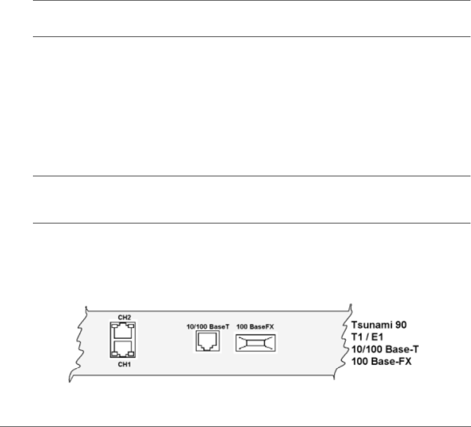
Lynx.GX and Tsunami Wireless Radio Installation and Maintenance
Port/Circuit Connections by Model
The following connection types are illustrated in the figures that follow.
10/100 BaseT / 100 BaseFX
The Tsunami Bridges use 100 Base-TX and 100 Base-FX RJ-48 modular port connectors and ST
connectors for the Fast Ethernet interface. They carry the signals in and out of the radio.
CHn
T1 or E1 data channels.
T1
A wayside data channel for T1 (DSX-1) interface voice connection. This channel does not affect the
Ethernet traffic.
E1
A balanced (120 ohm) wayside data channel for CEPT-1 interface connections.
Note: If an unbalanced 75 ohm connection (RJ-45 connector) is required, an optional 75ohm to 125
ohm balun will provide this interface. If you cannot locate these devices, contact Customer
Support.
DS-3
The connection for the DS-3 signal is BNC female (75 Ohm, unbalanced).
DS-3 input: 75 ohms unbalanced connection, shield floating with respect to chassis ground (user may
ground this shield if necessary).
DS-3 output: 75 ohms, configured by default as single-ended, with shield connected to chassis ground.
Note: DS-3 output can be changed to a 75 ohm output with shield floating with respect to chassis
ground by repositioning an internal jumper. This alternate configuration is recommended if the
shield is already grounded at the receiving end of the cable. Contact customer service for more
information.
10/100 Base-T and 100 Base-FX Ethernet Connections
The radios use 10/100 Base-T and 100 Base-FX RJ-48 modular port connectors and ST connectors for the
Fast Ethernet interface. They carry the signals in and out of the radio.
Figure 9 IDU Front Panel – Data Interface (Middle section)
Chapter 3. Installing the Unit 2-45
CPN 62140 12/01/02
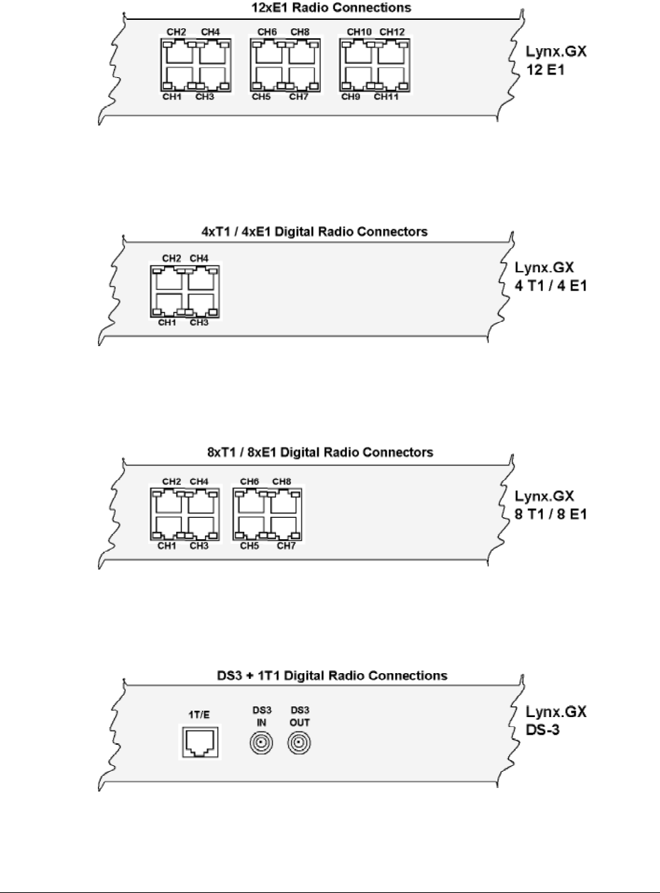
Lynx.GX and Tsunami Wireless Radio Installation and Maintenance
12xE1 Radio Connections
Figure 10 12xE1 Radio Connections
4xT1 and 4xE1 Connections
Figure 11 4xT1 and 4xE1 Connections
8xT1 and 8xE1 Connections
Figure 12 8xT1/8xE1 Digital Radio Connections
DS-3 Digital Connections
Figure 13 DS-3 Digital Radio Connections
Chapter 3. Installing the Unit 2-46
CPN 62140 12/01/02
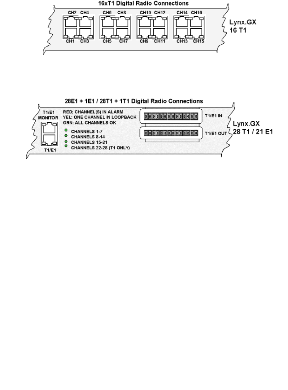
Lynx.GX and Tsunami Wireless Radio Installation and Maintenance
16xT1 Connections
Figure 14 16xT1 Digital Radio Connections
21xE1 and 28xT1 Connections
Figure 15 21xE1 and 28xT1 Connections
Chapter 3. Installing the Unit 2-47
CPN 62140 12/01/02

Lynx.GX and Tsunami Wireless Radio Installation and Maintenance
Chapter 3. Installing the Unit 2-48
CPN 62140 12/01/02

Lynx.GX and Tsunami Radio Installation and Configuration
Appendix A. Troubleshooting
This chapter provides information about:
■ Maintaining the radio
■ Troubleshooting data stream errors and interference
■ Troubleshooting alarms
■ Measuring radio function
■ Troubleshooting radio management tools
■ Repair policy
Maintaining the Radio
The radio does not require any regular maintenance. However, it is prudent to monitor the radio link at
regular intervals to ensure that the link conditions are not changing. When visiting a radio site for
maintenance, you should check the following items and record the results:
■ RSL voltage
■ Power voltage
■ Far-end RSL voltage
■ Alarm conditions
Also, be sure to verify that the unit has adequate ventilation and that the security ID is set similarly at each
unit through the network management system.
If any alarm conditions exist, you should record them. See “Troubleshooting Alarms” on page 55.
Data Stream Errors
When the radio is in service, errors in the data stream may occur. This is usually known to the operator
either by faulty data indications of downstream equipment or by external bit error rate testing.
It is possible that no alarms appear on the front panel during normal operations, even when there are errors
present in the data stream.
Some errors do not result in an alarm (such as bipolar violations, slow “dribbling” errors, improperly
terminated connections or incorrect settings), but are exhibited on downstream data processing equipment or
during a BER test.
In other cases, there may be data errors due to atmospheric conditions (fading), interference, or other
reasons, but not at a high enough error level to be indicated with the BER alarm LED. In the case of these
types of errors, the following information can be helpful to troubleshoot the radio link.
Appendix A Troubleshooting 3-49
CPN 62140 12/01/02

Lynx.GX and Tsunami Wireless Radio Installation and Maintenance
Indications
■ During external BER test, test equipment indicates errors
■ Downstream equipment (mux, channel bank, codec, router, and so on) indicates errors
Possible Causes
■ Path fading due to atmospheric conditions
■ Poor transmission line connections
■ Antenna problems, misalignment or path clearance
■ Received signal level (RSL) is too strong
■ Far-end radio transmitter circuitry is faulty
■ Near-end radio receiver circuitry is faulty
■ Interference
Recommended Actions
■ Verify 100 Base-T wiring
■ Follow the troubleshooting instructions described in “Radio Fail Alarms.”
Changing Frequency Plans
The information in this section can be used for indoor unit models only.
The Lynx.GX frequency selections are listed in “Frequency Plan Determination.” The near-end radio and the
far-end radio must be corresponding (for example, A1 / A2).
The frequency of a given Lynx terminal is set by:
■ The specific filter
■ The physical orientation of this assembly
■ A setting within the CONFIG port (see “CONFIG Port Command Line Interface”).
With respect to a given filter, the frequencies are fixed, because tuned RF filters are required for normal
operation. Changing of the (pre-tuned) radio frequencies may be required when installing spares or for
special situations (such as interference mitigation). This is accomplished by installing an alternate filter.
1. Remove any cables connected to the antenna connector on the diplexer (filter) and then remove the two
screws that mount the filter to the Lynx chassis.
2. Slowly remove the filter from the chassis being careful to not endanger the cables that are connected to
the rear side of the filter.
3. Disconnect the two SMA connectors that are attached to the rear of the filter with a 5/16-inch open end
wrench.
4. Select the new filter such that the frequency channel label on the filter corresponds to the desired
frequency channel (or rotate filter if applicable).
Appendix A Troubleshooting 2-50
CPN 62140 12/01/02

Lynx.GX and Tsunami Wireless Radio Installation and Maintenance
5. Connect the two SMA connectors to the new or reoriented filter with the 5/16-inch open end wrench.
6. Slowly place the wired filter assembly so that it is flush with the rear panel.
7. Install the two screws that mount the filter to the rear panel.
8. Modify the operating frequency as described in the CONFIG menus.
9. Single-band versions of this radio can be interchanged from A1 to A2 by changing (but not rotating) the
installed filter. After the filter is changed, you must change the frequency settings within the
configuration menu (NMS) to match the installed filter.
Dual-band versions of this radio can also change channels, but the orientation of low-side or high-side
transmit must be retained. That is, an A1 radio can only be changed into a B1 radio with a new filter, but
not into an A2 or a B2. Likewise, the A2 radio can only be changed into a B2 radio with a new filter, but not
into an A1 or B1. The diplexer filters can go on any radio and must be properly oriented. After the filter is
changed, you must change the frequency setting within the configuration menu (NMS) to match the installed
filter.
Servicing Channel Orientations
For dual-band units, a spare of each band may be required. For single-band units, one spare Lynx terminal
can service both channel orientations. See “Changing Frequency Plans” for how to change frequencies of a
spare radio.
Customers with several radios, or radios in critical operations, are encouraged to purchase one or more spare
radios of each model in their system. This allows for rapid restoration of radio service in the unlikely event of
a radio failure.
Counteracting and Evaluating Interference
The recommended interference countermeasures available are:
■ Short paths
■ Narrow beam antennas (high gain)
■ Frequency selection
■ Antenna Polarization
■ Transmit Power
■ Equipment/Antenna Location
■ Use of a Spectrum Analyzer to evaluate potential interference
Short Paths
The single most effective countermeasure against interference is to maintain “short path” length. This may be
achieved by dividing long paths into multiple small paths by cascading hops. Intermediate repeaters can be
formed using back-to-back Lynx terminals and transmit output power reduced, if required.
Appendix A Troubleshooting 2-51
CPN 62140 12/01/02

Lynx.GX and Tsunami Wireless Radio Installation and Maintenance
By definition, “short path” is defined as a path where fades are extremely rare and signal levels vary by no
more than ±3 dB during fades. This distance varies with the RF frequency. Typically a “short path” is defined
as any path length shorter than 5 miles at 5.3/5.8 GHz.
Narrow Beam Antennas (High Gain)
This is the next most effective countermeasure. Narrow-beam antennas ensure that the transmitted power is
sent in a single direction; this minimizes the possibility of causing interference inadvertently to other users.
Narrow beam antennas also reject off-azimuth signals being received from potential sources of interference
and have high gain, which boosts desired receive levels and improves the carrier-to-interference ratio.
When selecting narrow beam antennas, it is helpful to know that larger antennas generally out-perform
smaller antennas. Another important antenna specification is the front-to-back ratio, which ensures rejection
of unwanted signals from azimuth angles behind the antenna.
Frequency Selection
The Lynx radios offer several distinct non-overlapping frequency channel plans (see “Determining the
Frequency Plan” on page 16 and “Changing Frequency Plans” on page 50) and the unit’s RF filter can reject
interference more than 10 MHz away from the receive frequency.
Offset frequencies combined with other countermeasures may enable several receive channels to operate at
a single hub site. Because of the limited spreading ratio used, frequency selection is more efficient than code
selection for interference rejection when operating multiple Lynx terminals at a single site.
You often can overcome interference by exchanging frequencies of both ends of the radio link (for example,
change your A1 terminal to an A2 and change the other end from an A2 to an A1). Also, changing channel
plans (for example, from A to B) can be very effective.
Note: The information in this section can be used for indoor unit models only.
The Lynx frequency selections are listed in “Determining the Frequency Plan” on page 16. The near-end
radio and the far-end radio must be corresponding (such as A1 / A2).
The frequency of a given Lynx terminal is set by the specific filter, the physical orientation of this assembly,
and a setting within the CONFIG port.
With respect to a given filter, the frequencies are fixed, because tuned RF filters are required for normal
operation. Changing of the (pre-tuned) radio frequencies may be required when installing spares or for
special situations, such as interference mitigation. This is accomplished by installing an alternate filter.
1. Remove any cables connected to the antenna connector on the diplexer (filter) and then remove the two
screws that mount the filter to the Lynx chassis.
2. Slowly remove the filter from the chassis, being careful to not endanger the cables that are connected to
the rear side of the filter.
Appendix A Troubleshooting 2-52
CPN 62140 12/01/02

Lynx.GX and Tsunami Wireless Radio Installation and Maintenance
3. With a 5/16-inch open end wrench, disconnect the two SMA connectors that are attached to the rear of
the filter.
4. Select the new filter such that the frequency channel label on the filter corresponds to the desired
frequency channel (or rotate filter if applicable).
5. Connect the two SMA connectors to the new or reoriented filter with the 5/16-inch open end wrench.
6. Slowly place the wired filter assembly so that it is flush with the rear panel; install the two screws that
mount the filter to the rear panel.
7. Modify the operating frequency as described in the CONFIG menus (see “CONFIG Port Command Line
Interface” Error! Bookmark not defined.).
8. Single-band versions of this unit can be interchanged from A1 to A2 by changing (but not rotating) the
installed filter.
After the filter is changed, the frequency settings within the configuration menu (NMS) must be changed
to match the installed filter.
Dual-band versions of this unit also can change channels, but the orientation of low-side or high-side
transmit must be retained. That is, an A1 unit can only be changed into a B1 unit with a new filter, but
not into an A2 or a B2. Likewise, the A2 unit can only be changed into a B2 unit with a new filter, but
not into an A1 or B1. The diplexer filters can go on any radio and must be properly oriented. After filter
is changed, the frequency setting within the configuration menu (NMS) must be changed to match the
installed filter.
Servicing Channel Orientations
For dual-band units, a spare of each band may be required. For single-band units, one spare Lynx terminal
services both channel orientations.
Customers with several units, or units in critical operations, are encouraged to purchase one or more spare
radios of each model in their system. This allows for rapid restoration of radio service in the unlikely event of
a radio failure.
Antenna Polarization
Cross-polarized antennas can provide approximately 20 to 30 dB discrimination of unwanted signals. The
actual discrimination depends upon the antenna design and any rotation of polarization along the path (for
example, due to reflections). Discrimination only exists between two orthogonal polarizations:
■ Vertical versus horizontal
■ Left-hand circular versus right-hand circular
There is only 3 dB discrimination between circular and linear (vertical or horizontal) polarization.
Interference can sometimes be overcome by changing antenna polarization at both ends of the link.
Appendix A Troubleshooting 2-53
CPN 62140 12/01/02

Lynx.GX and Tsunami Wireless Radio Installation and Maintenance
Transmit Power
The maximum level into the receiver is -30 dBm. Errors can occur in the receive data stream above this
level. You should reduce transmit output power on very short paths to avoid overload.
Equipment/Antenna Location
Interference is occasionally caused by the unit or the antenna being too close to another similar transmitter.
Moving the unit, the antennas, or the interfering equipment can reduce or eliminate interference.
Interference countermeasures rely to some extent on the measurement of the received interference level and
frequency. Before turning up a new hop, use a spectrum analyzer to monitor the spectrum at each end to
check for possible interfering signals. For more details, see the section that follows.
Use of a Spectrum Analyzer to Evaluate Potential Interference
Connecting to the antenna and using “peak hold” on a spectrum analyzer, the spectrum across the receive
frequency range of the radio can be swept and any signals being received at levels above the radio's specified
threshold identified.
If potential interfering signals are found, you can change the Lynx frequency plan to avoid a receive channel
that may contain significant interference (see “Changing Frequency Plans” on page 50). For example,
interference can be reduced by moving from the A1/A2 plan to the B1/B2 plan, or by swapping terminals or
RF filters so that A1 becomes A2. Signals outside the receiver frequency range can be ignored: they do not
cause interference.
If a spectrum analyzer is not available, you can use the RSL voltage to indicate the background noise and
interference level within the receiver RF filter band when the far-end transmitter is turned off. With the far-
end radio turned off, if an RSL voltage level above the radio's threshold level is measured, there is potential
interference in this frequency channel.
When using a spectrum analyzer for determining the presence of interference, use very narrow resolution
bandwidth settings to detect signals down to the unit’s threshold (approximately -80 dBm, depending upon
the type of radio).
Appendix A Troubleshooting 2-54
CPN 62140 12/01/02

Lynx.GX and Tsunami Wireless Radio Installation and Maintenance
Troubleshooting Alarms
Use these troubleshooting guidelines when you receive:
■ RF Link Alarms
■ Radio Fail Alarms
■ Far End Alarms
RF Link Alarm
This LED indicates that the demodulator function is not synchronizing with the intended received signal.
Possible Causes
■ Severe path fading due to atmospheric conditions, usually accompanied by low RSL voltage reading
■ Poor transmission line connections, usually accompanied by low RSL voltage reading
■ Antenna problems, misalignment, or path clearance, usually accompanied by low RSL voltage reading
■ Improper radio settings (such as frequency channel)
■ Received signal level (RSL) is too strong
■ Interference
■ Far-end radio transmitter circuitry is faulty
■ Near-end radio receiver circuitry is faulty
■ Link security ID not the same for each radio
Recommended Actions
Check the following at each end of the link:
■ Verify that rear panel filters are opposite channel plans on each end (for example, one is A1 and other is
A2).
■ Verify that radio frequency settings match each installed filter using the NMS Config menu.
■ Verify that all connections between radios and antennas are secure and all devices between radios and
antennas are rated for the radio frequency band (5.3/5.8 GHz).
Measure RSL by placing a voltmeter across RSL and GND test points and:
1. Comparing this voltage to the Factory Test Data Sheet and estimating the RSL in dBm.
2. Comparing this to the RSL that was expected using path calculations (see “Calculating RSL and Link
Budget” on page 15).
3. Pressing and holding the DISPLAY FAR END button and measuring the far-end RSL (while continuing to
hold the button) or on those models without FAR-END RSL on the front panel, using the built-in browser
software to acquire the near-end and far-end RSLs.
Appendix A Troubleshooting 2-55
CPN 62140 12/01/02

Lynx.GX and Tsunami Wireless Radio Installation and Maintenance
4. Comparing these RSLs to the Factory Test Data Sheet for the far-end radio and estimating the RSL in
dBm.
5. Comparing this RSL to the expected RSL from the link budget calculations.
Excessive Loss
If RSL from both ends of the radio are approximately the same as each other, but lower than anticipated for
this installation, then the likely cause of the BER alarm is excessive losses between the radios. Excessive loss
problems could include the transmission line at either end, all adapters, connectors, the antennas, the
antenna alignment, as well as the path itself (any obstructions or clearance problems).
Verify antenna alignment, line-of-sight, and path clearance; if this does not improve RSL, check all devices
between the radios and their antennas at both ends. Make sure all transmission lines, connectors, and any
other devices are properly rated for operation at the radio's frequency (5.3/5.8 GHz).
Power Adjustment
If only one end has low RSL, this could be caused by low transmit output power from the opposite end radio.
Verify that the transmitter output power of the radio opposite to the low RSL receiver has been set in
accordance to path calculations or EIRP restrictions (where applicable).
Power adjustment must be performed by professional installation personnel only. The PWR test
point can be used and compared with the Factory Test Data Sheet; the front panel recessed potentiometer
can be turned clockwise to increase power. If an RF power meter is available, you can connect it to the RF
output of the radio for precision measurement. This test also verifies that the radio transmitter is working
properly.
If one terminal (or both) has high RSL, this could be caused by a very short path or interference.
Short Path or Interference
To verify the possible presence of interference, remove DC power to the unit opposite the one that is reading
high RSL. Once power is removed, measure RSL on the remaining radio. If RSL voltage is lower than that
listed for “Threshold” in the Factory Test Data Sheet, an interfering signal is present.
If interference is suspected, the easiest potential remedy is to swap frequency channels on both sides of the
link. (see “Changing Frequency Plans” on page 50). Swap terminals at both ends of the link so they are the
opposite of their original installation. After both ends are moved, reconnect the radios and determine
whether the BER alarm is still active. If so, you can install other frequency channels or try other interference
counter-measures, as discussed in “Counteracting and Evaluating Interference” on page 51.
Appendix A Troubleshooting 2-56
CPN 62140 12/01/02

Lynx.GX and Tsunami Wireless Radio Installation and Maintenance
Possible Radio Failure
If all path related and data input problems have been pursued and the BER alarm is still active, the problem
could be related to a radio failure. Although radio failure typically is indicated by more severe alarm
conditions, it is possible that one of the radios may be out of specification, and this could be the cause of the
BER alarm. A back-to-back test verifies proper radio operation. See “Back-to-Back Testing” on page 58 for
more information. A threshold test on both radios, along with a test to verify proper RF output power, would
be beneficial.
Perform a back-to-back test before returning any radio terminal to the factory for repair. A back-to-back test
verifies radio operation.
If the radios pass their back-to-back testing successfully, the problem is likely with the path, with the
connections between the radio and the antenna, or interference. Before you reinstall the radios, be sure to
set the output power to the appropriate level for the installation.
Radio Fail Alarms
This LED indicates a known problem with the radio hardware.
Possible Causes
■ Internal synthesizers are unlocked
■ Internal digital circuits have failed
Recommended Actions
1. Remove power from the unit.
2. Verify that the correct frequency is configured on the browser Configuration tab.
3. Check to make sure power supply voltages are within specification.
4. Reapply power to the unit, even if the voltages were within specification.
If the RADIO FAIL alarm clears, place the radio back into service.
If the RADIO FAIL alarm does not clear, perform a back-to-back test to verify radio operation.
If the RADIO FAIL alarm is still active in a back-to-back test, return the radio to the factory for repair.
Far End Alarms
This LED indicates that there is an alarm condition present on the far-end radio. When the DISPLAY FAR END
button is pressed (and held), the status LEDs indicate the alarm conditions of the far-end radio.
Possible Causes
One or more alarm condition(s) exist on the far-end radio.
Appendix A Troubleshooting 2-57
CPN 62140 12/01/02
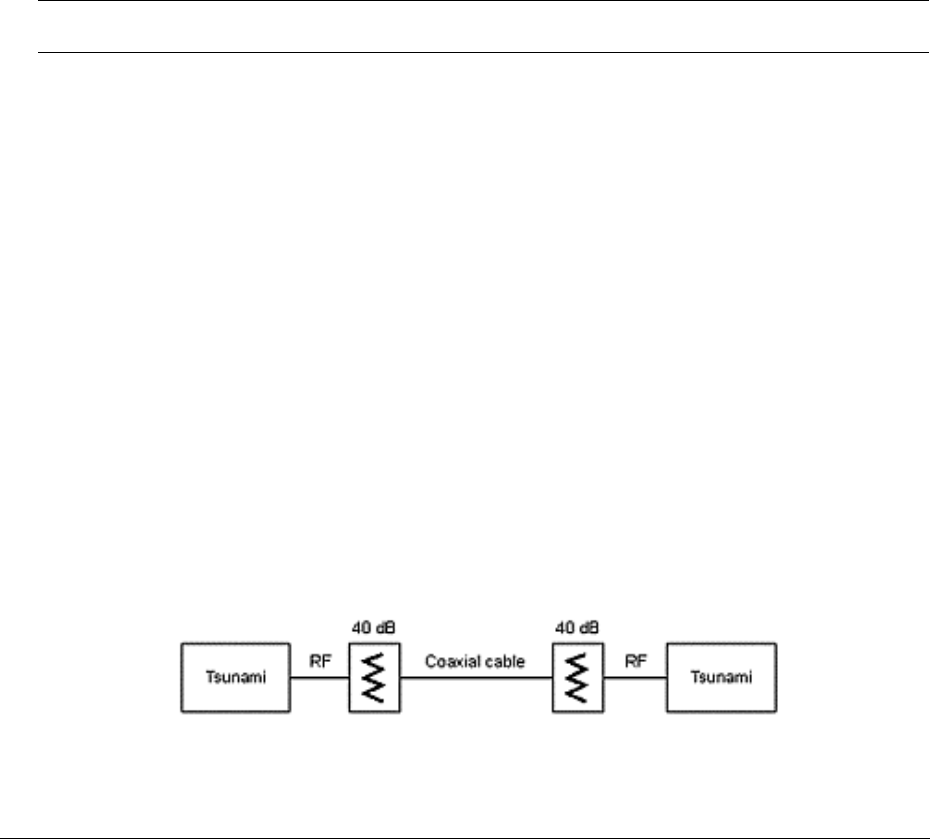
Lynx.GX and Tsunami Wireless Radio Installation and Maintenance
Recommended Actions
Press and hold the DISPLAY FAR END button and observe the LED status.
Follow the troubleshooting instructions provided in “RF Link Alarms” and “Radio Fail Alarms.”
Measuring Radio Function
You can measure radio function using Back-to-Back Testing and Link Testing, which are described in this
section.
Back-to-Back Testing
Back-to-back testing is an ideal method of testing the Lynx radio. This testing eliminates link problems
caused by auxiliary equipment, installation, or the radio path, and isolates potential radio hardware
problems.
Note: Back-to-back testing must be performed to verify a radio problem before returning any radio to
the factory for repair.
Required Equipment for Test
Back-to-back testing must be performed with both radios at the same location. The following test equipment
is required:
■ DC power source capable of supplying approximately 90 Watts (total) to the radios (or two AC adapters)
■ One low-loss coaxial cable, N-to-N male
■ One (or more) coaxial in-line calibrated fixed attenuators, 40 to 80 dB total attenuation
The following test equipment may also be useful for further testing of the radio:
■ BER tester
■ Variable (60 dB range or more) RF attenuator (rated for the proper frequency, 2.4 or 5.8 GHz)
■ RF power meter
When the equipment is connected as shown in the following figure, both radios should have no alarm
conditions. If these conditions have been met, it is likely that the radio is operating in accordance to
specifications. If errors or alarms occur during this test, verify alarm status. If alarms or errors are still
present, the radio is likely to be faulty.
Figure 16 Back-to-Back Test Configuration
Appendix A Troubleshooting 2-58
CPN 62140 12/01/02
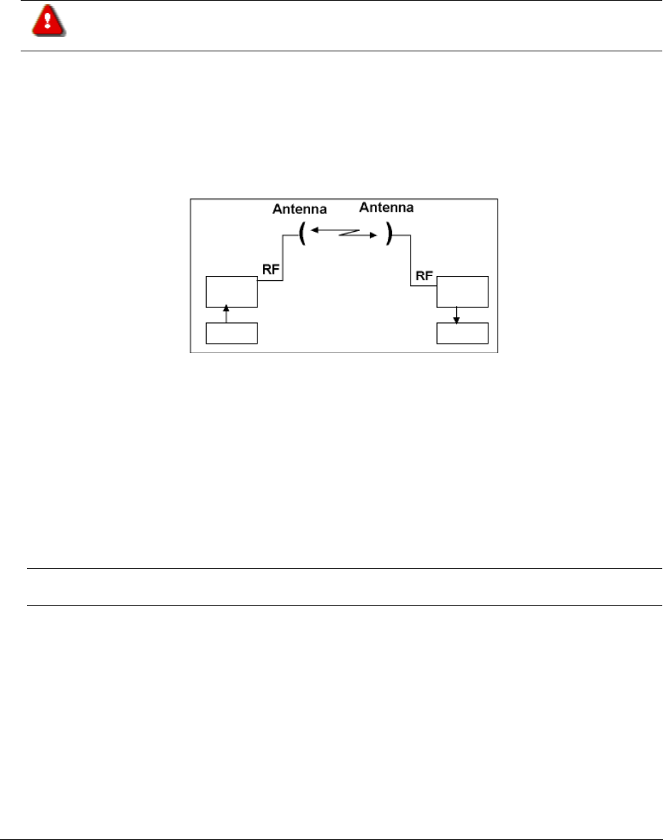
Lynx.GX and Tsunami Wireless Radio Installation and Maintenance
If further troubleshooting is required, you can insert a variable RF attenuator between the radios to fade
down the path to determine that the threshold specification is being met. You can run the threshold tests in
both directions to isolate the radio problem (if any). See “Link Testing” below for more information. You
can use an RF power meter to individually test each radio’s output power.
The Lynx radios will be damaged if appropriate attenuation is not supplied between
radios. You must provide a minimum of 40 dB and no more than 80 dB attenuation
between the two radios.
Link Testing
Link testing is the preferred way to evaluate a radio link's performance. It can be performed from end-to-
end or in link test mode (which tests both directions of the radio path). The following figure illustrates a
typical test configuration (which may include the radio’s path instead of in-line attenuators).
Figure 17 Link Testing Configuration
When performing testing, make sure of the following:
■ Disconnect all 100 Base-T inputs and outputs to both radios
■ Verify all configuration settings
You can perform link testing on the bench with two terminals back-to-back, or over the radio path. Also, it
can be performed from end-to-end (which requires two 100BaseT test sets over a link, the far-end unit
slaved to the near-end unit's clock) or in loopback mode.
Note: If link testing indicates an unacceptable level of errors, follow the instructions in “RF Link Alarms”
or perform a back-to-back test as described in “Back-to-Back Testing” on page 58.
Troubleshooting Management Tools
The following two scenarios may help you troubleshoot management functions.
Appendix A Troubleshooting 2-59
CPN 62140 12/01/02

Lynx.GX and Tsunami Wireless Radio Installation and Maintenance
Troubleshooting the Console Management Tool
Problem
■ Non-functioning CONFIG port
■ No access to the main menu
Solution
To verify your PC settings and RS-232 cable, bring up a HyperTerminal session with one end of the cable
plugged into the PC com port and the other end unplugged.
Using a piece of wire, short pins 2 and 3 together on the unplugged end of the cable. Make sure the
HyperTerminal window is active and enter some characters from the keyboard. You should see the
characters displayed in the HyperTerminal window. If you cannot see the characters, make sure the com
port settings are correct and try a different cable.
Double-check the HyperTerminal configuration settings and plug the cable back into the radio config port.
If the characters displayed as previously described, the HyperTerminal configurations are correct, and the
menu still is not displayed when you press the Enter key twice, the config port may already be “logged in.”
Once you are logged in to the Config menu, the config port stays logged in for the timeout period specified
under Main Menu item 4, User Configuration. The default is 7200 seconds or 2 hours.
If you unplug the cable or shut down HyperTerminal while you are still logged in and you restart the
HyperTerminal session, it appears as if you have a blank screen that is not responding.
To get started again, press the <Tab> key a few times. If you were in a screen with multiple entry fields
when you shut down, you will see the cursor move between those fields. Bring the cursor back to the
command field on the lower right part of the screen and press the <H> key followed by Enter to go back to
the Main Menu.
To log out of the config port, go to the command field and press the <H> key; then press Enter to go to
the Main Menu. Then press <O> and Enter to go to the Logon menu.
From the command field in the logon screen, press <D> and Enter to end the session. Pressing Enter twice
restarts the session and brings up the logon screen.
Appendix A Troubleshooting 2-60
CPN 62140 12/01/02

Lynx.GX and Tsunami Wireless Radio Installation and Maintenance
Troubleshooting the Web Interface Management Tool
Problem
■ Slow Web Interface
■ Unable to logon to the Web Interface
Solution
Check the Ethernet duplex settings of the NMS port and the PC or switch connected to it. If the NMS port is
set to full duplex and the device connected to it is set to half duplex, or vice versa, the web browser still
works but is slow.
Make sure the duplex settings all match. The duplex setting for the NMS port can be set in the Config Port
menu, under submenu 3, Network Configuration, item 9, Ethernet Duplex. Ignore item 5, Ethernet
auto select access as it is an artifact from the original application from which the code was ported and has
no function.
Repair Policy
The Lynx terminal includes comprehensive alarm indicators designed to diagnose potential faults. Should a
fault occur, it often can be resolved by operator adjustment.
Should a fault occur that cannot be resolved by operator adjustment and has been confirmed by back-to-
back testing, the equipment should be returned to the factory for repair.
The Lynx radios are complex systems not designed for user repair. Do not remove the cover or open any
part of the terminal. The complete terminal should be sent back in its original packing material for factory
repair.
Contact the factory in advance of returning the product. You will be assigned a Return Material Authorization
(RMA) number that authorizes your return. Units sent to the factory without an RMA number may delay the
repair process.
Be sure to include the following information:
■ RMA number
■ Description of the problem
■ Your name and telephone number
■ Return shipping address
■ Urgency of repair
See the published Warranty policy for repair policy details.
Appendix A Troubleshooting 2-61
CPN 62140 12/01/02

Lynx.GX and Tsunami Wireless Radio Installation and Maintenance
Lynx radios should be packaged in their original packing boxes for shipment. Whenever possible, Proxim
Corporation can provide an empty box shipment to facilitate proper packaging. Regardless, proper and
adequate packaging must be used for shipments to protect the units from damage. Proxim Corporation
cannot be held responsible for any repairs due to inadequately packed materials. Damage caused by
improper packing will likely result in higher repair costs and delays. See “Warranty” for explicit product
warranty information.
Proxim Corporation provides 24-hour telephone technical support with purchased service plans. We do,
however, encourage you to troubleshoot your Lynx radio and link according to the troubleshooting methods
provided in this document.
Appendix A Troubleshooting 2-62
CPN 62140 12/01/02
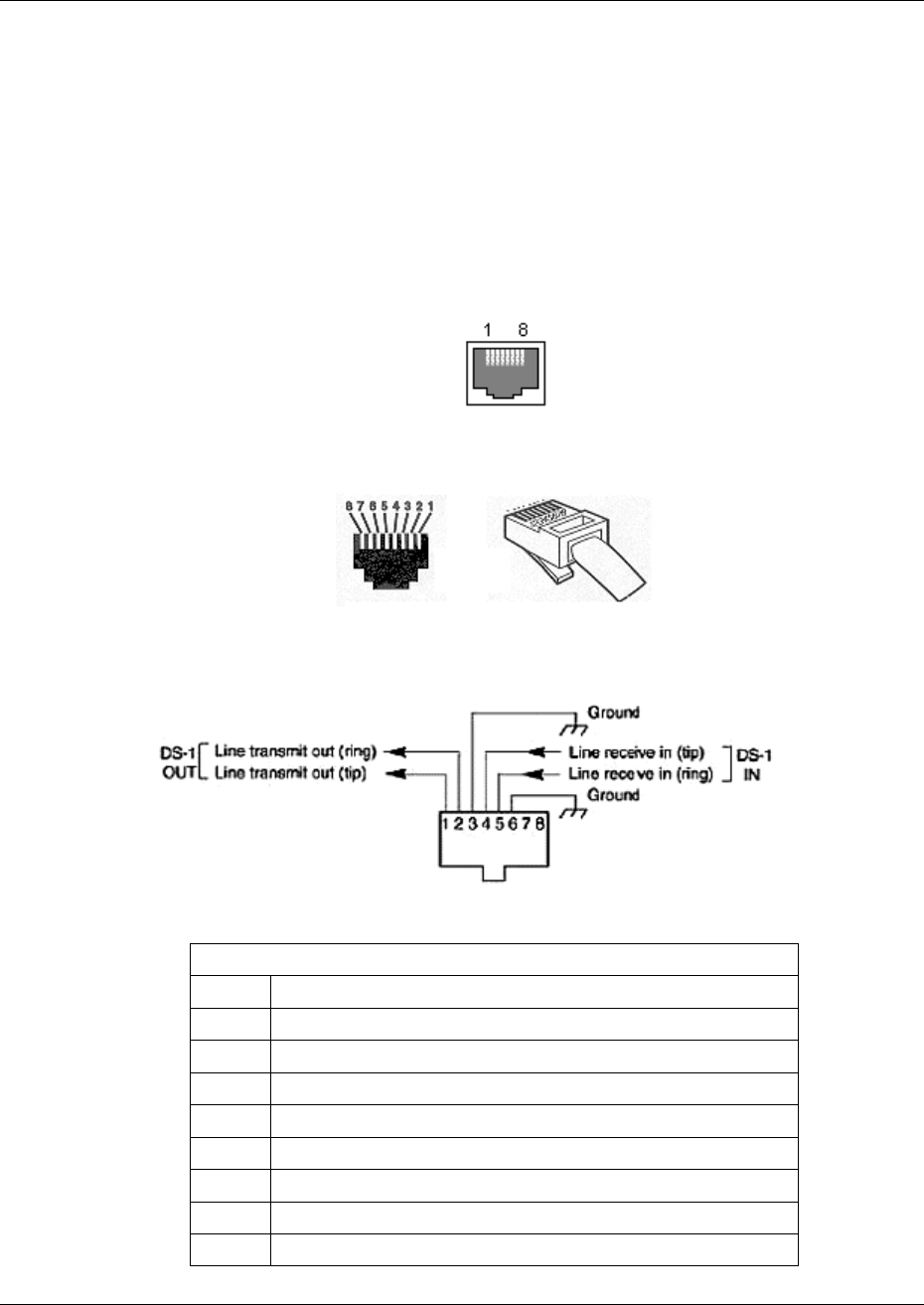
Lynx.GX and Tsunami Radio Installation and Configuration
Appendix B. Connectors and Pin Assignments
This appendix describes the Lynx.GX radio port connectors and pin assignments for the IDU (Indoor Unit) and
RF Unit.
IDU Main Traffic T1/E1 Connection
The main traffic ports for T1 or E1 formats appear on the front panel as multiple 8 pin modular jack
connectors wired per RJ48C. The following figures illustrates the traffic port pin assignment, followed by a
table listing the pin assignment descriptions.
8-Pin Modular Jack, Front View
8-Pin Modular Plug, Front and Top Views
T1/E1 Port Connector Pin Assignments
T1/E1 Traffic Port Connector Pin Assignment Description
Pin Description
1 DS-1 OUT-tip: Line transmit out (tip)
2 DS-1 OUT-ring: Line transmit out (ring)
3 GND: Chassis Ground
4 DS-1 IN-tip: Line receive in (tip)
5 DS-1 IN-ring: Line receive in (ring)
6 GND: Chassis Ground
7 NC: No Connection
8 NC: No Connection
Appendix B. Connectors and Pin Assignments B-63
CPN 62140 12/01/02
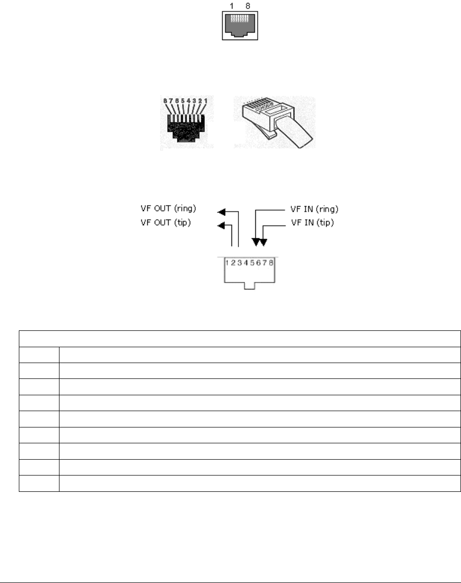
Lynx.GX and Tsunami Wireless Radio Installation and Maintenance
IDU VF Port
The front panel VF (Voice Frequency) Port supports standard audio interfaces (600 ohm balanced, 0 dBm
maximum level) on an 8 pin modular jack as shown below.
8-Pin Modular Jack
8-Pin Modular Plug
VF Port Connector Pin Assignments
VF Port Connector Pin Assignment Description
Pin Description
1 NC: No Connection
2 VF OUT-tip: Audio Output (tip)
3 VF OUT-ring: Audio Output (ring)
4 NC: No Connection
5 NC: No Connection
6 VF IN-ring: Audio Input (ring)
7 VF IN-tip: Audio Input (tip)
8 NC: No Connection
Appendix B. Connectors and Pin Assignments B-64
CPN 62140 12/01/02
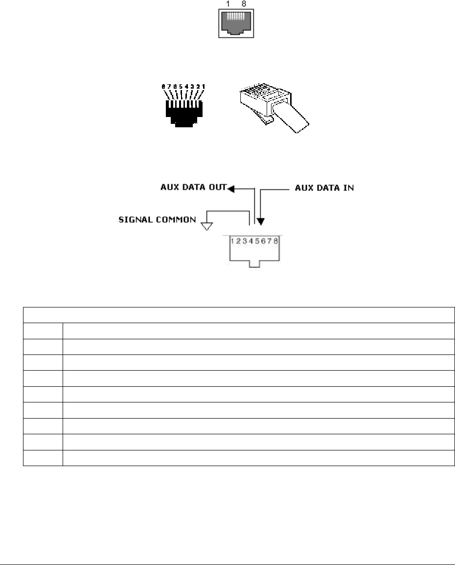
Lynx.GX and Tsunami Wireless Radio Installation and Maintenance
IDU Aux Data Port
The front panel Aux (Auxiliary) Data Port supports EIA-561 serial data on an 8 pin modular jack as shown
below. The data rate is user selectable to 2400, 4800, or 9600 bps. The asynchronous data is configured for
1 start bit, 8 data bits, and 1 stop bit.
8-Pin Modular Jack for Aux Port
8-Pin Modular Plug, Aux Port
Aux Port Pin Assignments
Aux Data Port Connector Pin Assignment Description
Pin Description
1 NC: No Connection
2 +3.3 V (Data Set Ready)
3 NC: No Connection
4 Common Signal/Chassis Ground
5 Aux Data Out
6 Aux Data In
7 +3.3 V (Clear To Send)
8 NC: No Connection
Appendix B. Connectors and Pin Assignments B-65
CPN 62140 12/01/02
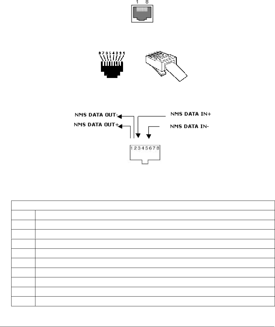
Lynx.GX and Tsunami Wireless Radio Installation and Maintenance
IDU NMS Port
The two front panel NMS (Network Management System) Port connectors (NMS1 and NMS2) support 10BaseT
and 100BaseT Ethernet serial data using two 8-pin modular jack connectors. Shown below is the wiring for
each connector per USOC 568B. Two jacks permit bridging to other Ethernet devices without the need for an
additional Ethernet hub or switch.
NMS Port Jack
NMS Port Plug
NMS Port Pin Assignments
NMS Port Connector Pin Assignment Description
Pin Description
1 NMS Data Out+
2 NMS Data Out-
3 NMS Data In+
4 *
5 *
6 NMS Data In-
7 *
8 *
* Connected to cross-talk suppression circuits.
Appendix B. Connectors and Pin Assignments B-66
CPN 62140 12/01/02
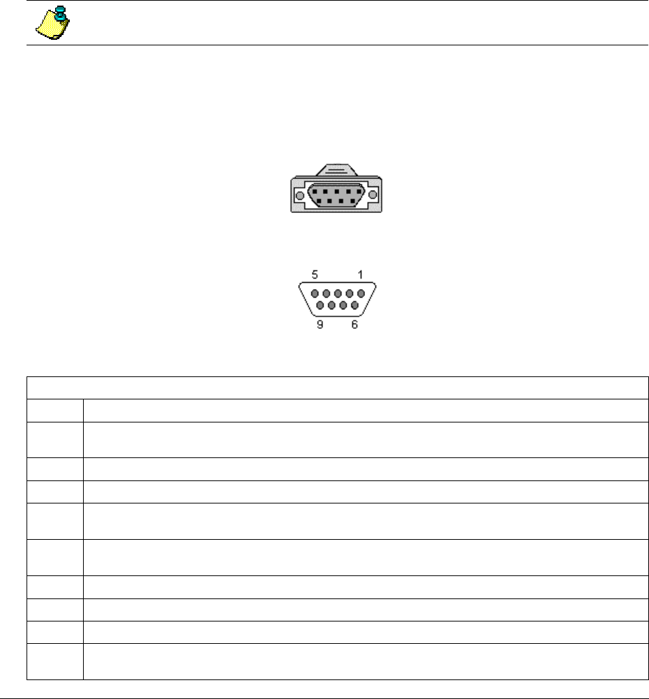
Lynx.GX and Tsunami Wireless Radio Installation and Maintenance
IDU Alarm Port Connector and Pin Assignment
External alarm outputs are provided using the 9-pin, D-type ALARM female connector. Two Form C summary
alarm relays capable of switching 30 VDC at 1A are provided. Both relays are energized in the normal state
and de-energized in the alarm state.
■ Summary alarm is activated by any near-end front panel LED alarm condition, including when the
internal test mode is enabled.
■ Out-of-service alarm is activated by any of the following alarm conditions: RF LINK, Radio Fail, Internal
Test
All alarms are active for a minimum of one second, or as long as the alarm condition persists,
which ever is longer duration.
Two alarm inputs are also available for monitoring dry switch contacts. Grounding an input causes the alarm
to go TRUE.
The following figure illustrates the Alarm port pin assignment followed by a table listing the assignment
descriptions.
DA9S Jack
DA9S Jack Pin-Out
Alarm Port Connector Pin Assignment Description
Pin Description
1 NO, Summary Alarm, Form C: normally open connection on summary alarm relay. Closed when
in alarm.
2 NC, Summary Alarm, Form C: normally closed connection on summary alarm relay.
3 COMMON CHASSIS/SIGNAL GROUND. Open when in alarm.
4 NO, Out-of-Service Summary Alarm, Form C: normally open connection on out-of-service
summary alarm relay. Closed when in alarm.
5 NC, Out-of-Service Summary Alarm, Form C: normally closed connection on out-of-service
summary alarm relay. Open when in alarm.
6 C, Summary Alarm, Form C: common connection on the summary alarm relay.
7 Contact Alarm 1 Input: 4.7K pull-up resistor to 3.3V, Alarm1 TRUE when grounded.
8 Contact Alarm 2 Input: 4.7K pull-up resistor to 3.3V, Alarm2 TRUE when grounded.
9 C, Out-of-Service Summary Alarm, Form C: common connection for the out-of-service summary
alarm relay.
Appendix B. Connectors and Pin Assignments B-67
CPN 62140 12/01/02
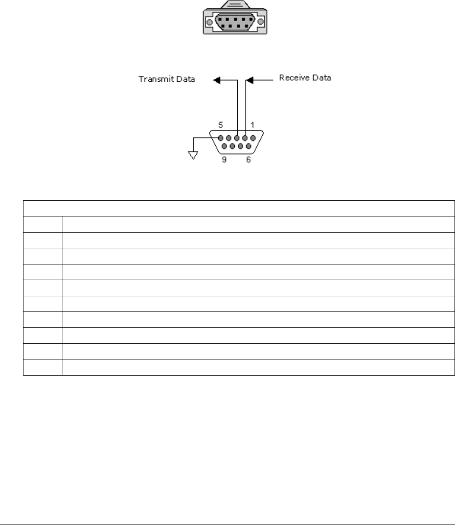
Lynx.GX and Tsunami Wireless Radio Installation and Maintenance
IDU Configuration Port Connector and Pin Assignment
Configuration (CONFIG) port connections to modems, computers, or terminals, as well as auxiliary data
connections, are made using a 9-pin, D-type, female connector. The CONFIG port is configured as a DTE
(Data Terminal Equipment) so a null modem cable is required when connecting to a DTE such as on a
standard PC Serial COM port.
The following figure illustrates the CONFIG port/AUX port connector.
IDU Config Port Connector (DA9S)
IDU Config Port Pin Assignments
Configuration Port Connector Pin Assignment Description
Pin Description
1 NC: No Connection (Data Carrier Detect)
2 Serial Data Input (Receive Data)
3 Serial Data Output (Transmit Data)
4 +3.3V (Data Terminal Ready)
5 Common Signal/Chassis Ground
6 NC: No Connection (Data Set Ready)
7 +3.3V (Request To Send)
8 NC: No Connection (Clear To Send)
9 NC: No Connection (Ring Indicator)
Appendix B. Connectors and Pin Assignments B-68
CPN 62140 12/01/02
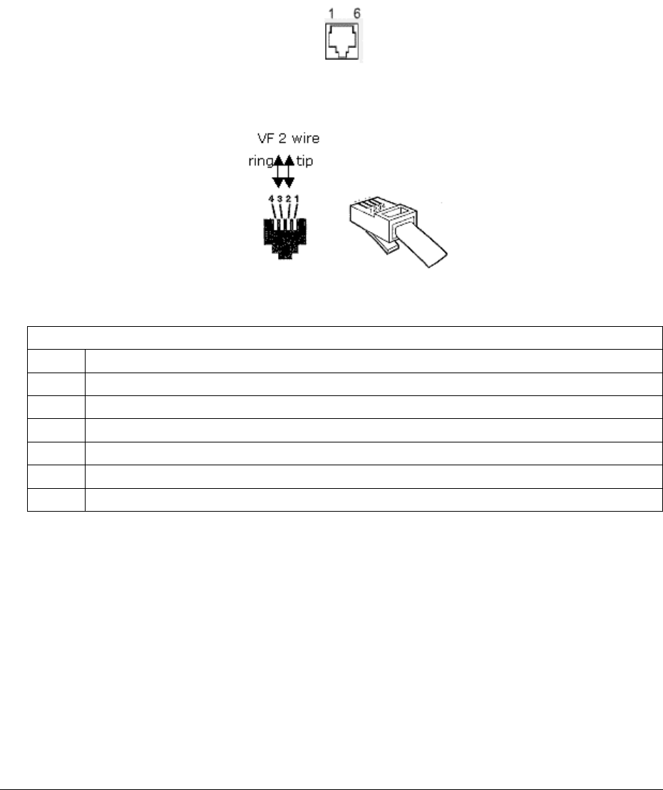
Lynx.GX and Tsunami Wireless Radio Installation and Maintenance
IDU Orderwire Handset Port
The IDU front panel Orderwire Handset Port supports connection to standard telephone handsets on a 6 pin
RJ12 modular jack as shown below. Note that 4 pin RJ11 modular plugs from standard handsets fit into 6 pin
modular jacks, automatically centering themselves. A two wire connection for VF interfaces can also be used
as shown.
RJ12 6-Pin Modular Jack, Front View
RJ11 4-Pin Modular Plug (typical handset termination)
Orderwire Handset Port Connector Pin Assignment Description
Pin Description
1 NC: No Connection
2 NC: No Connection
3 Orderwire Tip (pin 2 on RJ11)
4 Orderwire Ring (pin 3 on RJ11)
5 NC: No Connection
6 NC: No Connection
Appendix B. Connectors and Pin Assignments B-69
CPN 62140 12/01/02
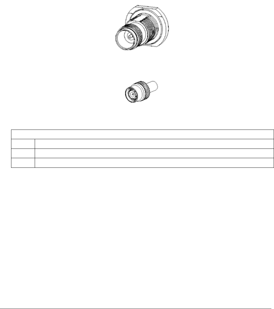
Lynx.GX and Tsunami Wireless Radio Installation and Maintenance
IDU/RFU Cable Connector and Pin Assignment
The IDU (Indoor Unit) is connected to the RFU (RF Unit) using a 50-ohm coaxial cable terminated with male
TNC (Threaded Neill Concelman) connectors on each end. The female TNC connector provides termination
for this coaxial cable on both the IDU front panel and RFU enclosures. The single coaxial cable carries power,
telemetry, receive IF signals, and transmit IF signals between the IDU and the RFU.
The following figure illustrates the IDU/RFU port TNC connector.
TNC Remale Front Panel Connector
TNC Male Connector, Coaxial Cable Termination
TNC Port Connector Pin Assignment Description
Pin Description
Center 42 VDC, 125 kHz Telemetry, 140 MHz Receiver IF, 748 MHz Transmitter IF
Outer Common Signal/Chassis Ground
Appendix B. Connectors and Pin Assignments B-70
CPN 62140 12/01/02
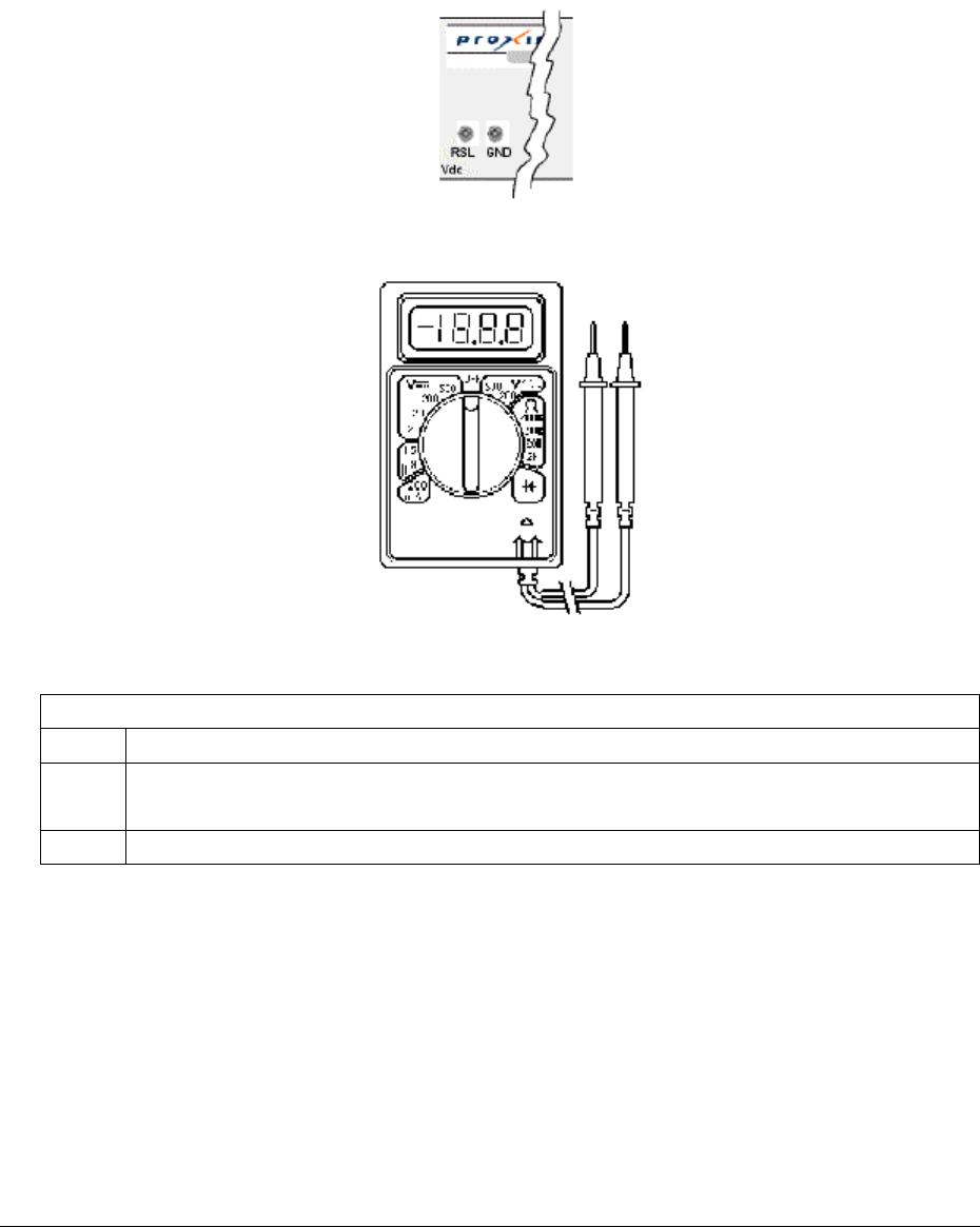
Lynx.GX and Tsunami Wireless Radio Installation and Maintenance
RSL and GND Connectors
The RSL (Received Signal Level) and GND (Ground) front panel connector are both single connection female
connectors that permit insertion of a 0.062” test probe pin from a VOM (Volt Ohm Meter).
Front Panel Test Points
Typical VOM Showing Test Probes
RSL and GND Connector Pin Assignment Description
Pin Description
RSL Received Signal Level: Voltage = -0.01 * RSL(dBm)
Example: +0.5 volts indicates a -50 dBm received signal level.
GND Common Signal/Chassis Ground
Appendix B. Connectors and Pin Assignments B-71
CPN 62140 12/01/02
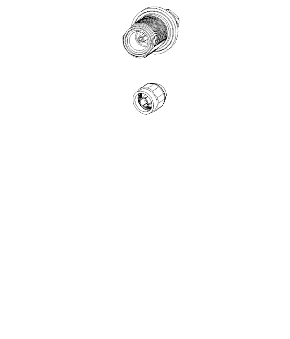
Lynx.GX and Tsunami Wireless Radio Installation and Maintenance
RFU/Antenna Connector and Pin Assignment
The RFU (RF Unit) is connected to the antenna using a 50 ohm coaxial cable terminated with male Type N
(Neill) connectors on each end. The female Type N connector provides termination for this coaxial cable on
the RFU enclosure and antenna assembly.
The following figure illustrates the RFU Antenna port Type N connector.
Antenna Type N Female Front Panel Connector
Antenna Type N Male Connector
TNC Port Connector Pin Assignment Description
Pin Description
Center Transmitter and Receiver RF
Outer Common Signal/Chassis Ground
Appendix B. Connectors and Pin Assignments B-72
CPN 62140 12/01/02
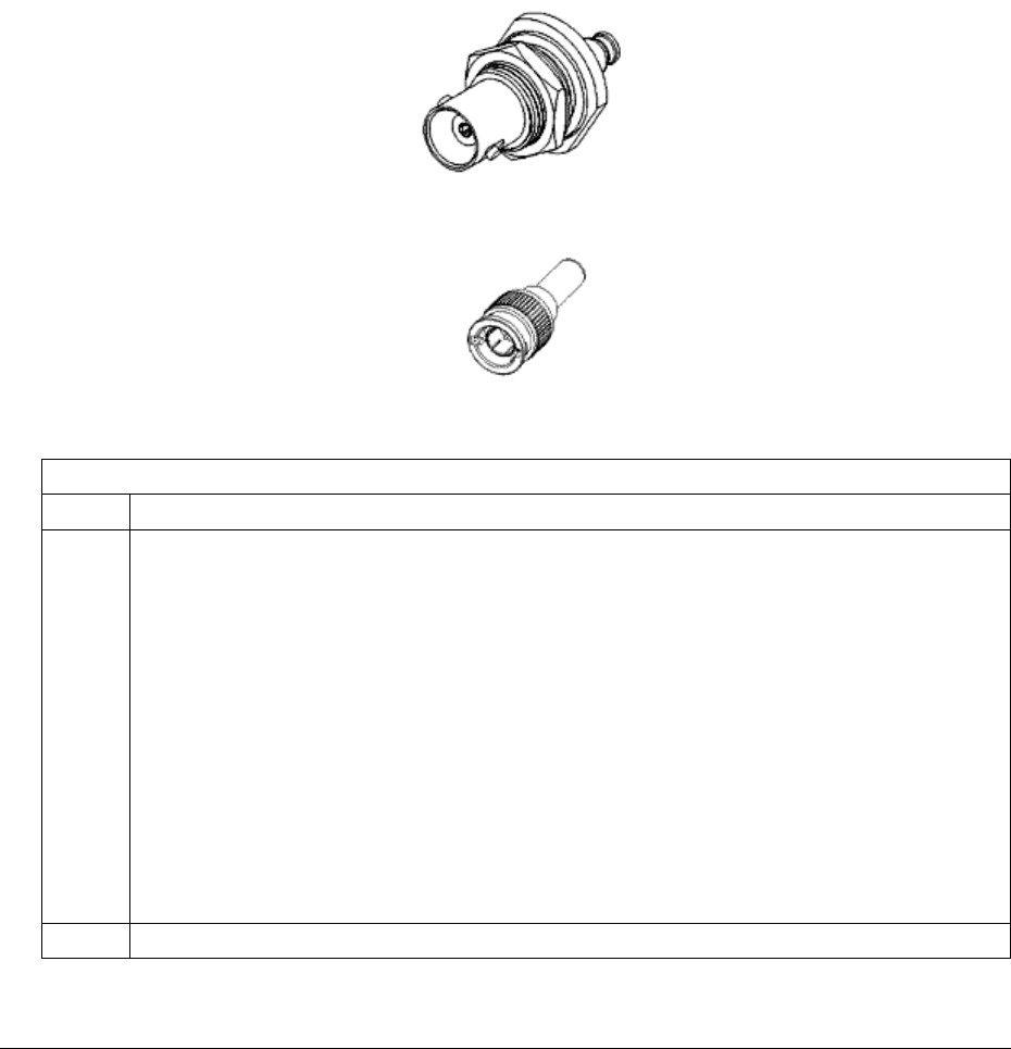
Lynx.GX and Tsunami Wireless Radio Installation and Maintenance
RFU RSL/Tone and Pin Assignment
The RFU (RF Unit) is provided with a BNC (Bayonet Neill Concelman) connector that provides a dual function
for assisting in antenna installation and steering:
• Provide a high impedance drive DC voltage level corresponding with the RSL (Received Signal
Strength). A standard DVM (Digital Volt Meter) is used for this purpose.
• Provide a low impedance drive AC voltage tone that indicates the RSL. This tone is monitored using a
40 ohm headset. A higher pitch tone indicates a stronger signal
The following figure illustrates the BNC connector.
RSL/Tone BNC Female Panel Connector
RSL/Tone BNC Male Connector to DVM or Headphone
BNC Port Connector Pin Assignment Description
Pin Description
Center DVM mode:
Lower voltages for higher strength signals:
Received Signal Level: RSL (dBm) = -100 * BNC (volts)
Examples: -70 dBm: 0.7 V
-50 dBm: 0.5 V
-30 dBm: 0.3 V
Earphone mode:
Higher pitch tones for higher strength signals:
BNC Audio: Tone Frequency (Hz) = 460800/(-2 * RSL (dBm) +76)
Examples: -70 dBm: 2133 Hz
-50 dBm: 2618 Hz
-30 dBm: 3388 Hz
Outer Common Signal/Chassis Ground
Appendix B. Connectors and Pin Assignments B-73
CPN 62140 12/01/02
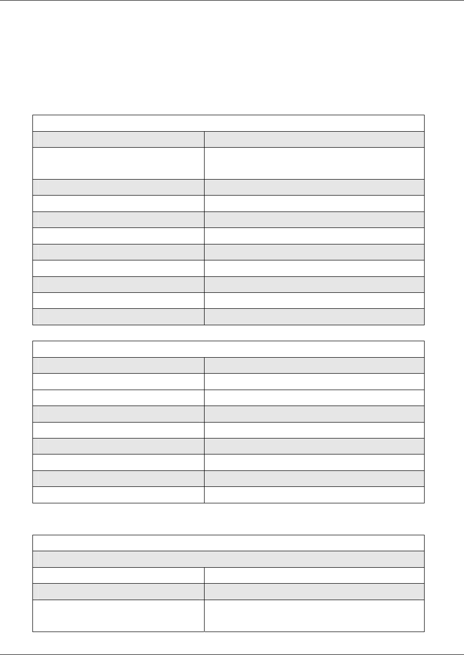
Lynx.GX and Tsunami Radio Installation and Configuration
Appendix C. Technical Specifications
Specifications that apply to all Lynx.GX models are presented in the next section, followed by the general
specifications for Tsunami models. Specifications that are specific to individual product types follow.
Lynx.GX General Specifications
General System Parameters
Operating Frequency 5.3 – 5.8 GHz
Product Configuration
1+0
IDU + RF Unit (RFU with outdoor option)
Digital Capacity 1.544 Mbps (T1) to 44.564 Mbps (DS-3)
Intermediate Frequency 749 MHz, 140 MHz (+/- 2 Mhz)
Digital Interface DSX-1, NxDSX-1, DSX-3; CEPT-1, NxCEPT-1
Error Floor 10-11
Latency (msec) <500 usec
Error Correction FEC, Reed-Solomon Decoding
Security 12 character Link ID code
Regulatory Compliance FCC Part 15.247 ISM; Part 15.407 U-NII
FCC ID HZB –US5358-GX1
Transceiver Specifications
Frequency Range 5.250 – 5.350 GHz, 5.725 – 5.850 GHz
Modulation type QPSK
System Gain See Unit specifications
Aggregate Data Rate See unit specifications
Transmit Output Power See Unit specifications
RF Transmit Power Range 20 dB
Transmit Frequency Stability ± 5 ppm
Receive Threshold at 10-6 BER See Unit specifications
Maximum Receive Level -20 dBm error free, 0 dBm without damage
Digital Interface (on IDU)
Main Line Interface
Interface DSX-1 (T1), DSX-3 (DS-3) or CEPT-1 (E1)
Line Rate 1.544 Mbps up to 44.564 Mbps
Connector(s) RJ-48C for 1 x T1 or E1, up to 16 T1 or 12 E1
64-pin DSX, 28T1 or 21 E1
Appendix C. Technical Specifications C-74
CPN 62140 12/01/02

Lynx.GX and Tsunami Wireless Radio Installation and Maintenance
Line Code T1: AMI or B8ZS, selectable; E1: HDB3
Line Buildout T1: 0 to 655 ft, selectable
Blue Code AIS (Alarm Indication Signal)
Regulatory Compliance DSX-1, DSX-3 (ANSI-T1-102-1987); CEPT-1 (ITU-T
G.703)
Wayside Channel
Interface DSX-1 (T1)
Connector RJ-48C, modular jack
Line Code AMI or B8ZS, selectable
Line Buildout 0 to 655 ft, selectable
Blue Code AIS (Alarm Indication Signal)
Regulatory Compliance ANSI-T1-102-1987
T1/E1 Monitor (Only on 28xT1 or 21xE1 models)
Interface DSX-1 (T1)
Connector RJ-48C
Signal Duplicate port for monitoring the transmit signal or
the receive signal of any of the 28 T1 or 21 E1
channels; independent control of line coding and
line buildout
Orderwire (for DTMF Handset)
Connector 2-wire, 4-pin mod jack RJ-11
REN 1.0 dB
DTMF Tones Within ± 1.5% of nominal frequency (+0 to 6 dB)
Ringing Voltage 48 Vdc, typical
Address 00 to 99
VF (Orderwire Bridge)
Connector RJ-45 jack (4-wire); bridged to Orderwire RJ-11
Input Level 0 dBm
Output Level 0 dBm
Impedance 600 ohm balanced
Configuration Port
Connector DB-9 DTE (female, 9 pin D sub)
Protocol RS-232 (8 bit data, No Parity, 1 Stop Bit)
Data Rate 9.6 kbps
Auxiliary Data Port
Connector RJ-45 DCE (modular jack, unkeyed)
Protocol RS-232 (8 bit Data, No Parity, 1 Stop Bit)
Data Rate 2.4 kHz, 4.8 kHz, 9.6kHz, 19.2 kHz
Alarms Port
Connector DB-9 (male, 9 pin D sub)
Appendix C. Technical Specifications C-75
CPN 62140 12/01/02
Lynx.GX and Tsunami Wireless Radio Installation and Maintenance
Form C Relay (NO, NC) Summary Alarm, Out-of-Service Alarm
Test Points RSL and Tx power output (DC voltage)
Network Management System
Connector RJ-45 (modular jack, unkeyed) 2 each
NMS 1 10/100 Base-Tx (out-of-band)
NMS 2 100Base-Tx (in-band)
Interface (RF Unit)
Antenna Port
Connector Type-N female
Impedance 50 ohms
Signal See Unit Specifications for frequency channels
IF Port
Connector TNC female
Impedance 50 ohms
Signal Uplink: 749 MHz; Downlink: 140 MHz; +48Vdc
Output RSL
Connector BNC female, cap and chain
Output Level 0.5 to 3.0 Vdc corresponds to -90 to –20 dBm
500 Hz to 3 kHz for earphone jack
Audio Tone RSL and RSL earphone connectors are combined
onto single connector
Fault and Configuration Management
Type Integral SNMP Agent
Integral Web Server
Serial Craft Terminal CLI
Telnet, via 10/100BT
100 Base-Fx Ethernet port In-band
RJ-45 modular jack
Auto-negotiate duplex
10/100 Base-Tx Ethernet port Out-of-Band
RJ-45 modular jack
Auto-negotiate speed and duplex
Configuration port VT-100 Craft Terminal; 9-pin D sub; 9600 baud
SNMP SNMP v2, MIB II, Proxim Enterprise MIB
Network Element Managers HPOpenView or equivalent
SNMP Reports Alarm traps sent to up to 5 Managers; via MIB
variables
Web Browser Compatibility Any IE version above 5.0 (5.0, 5.5, 6.0)
Netscape 6.1 in both Windows and Linux
Netscape 6.21 in Windows
Appendix C. Technical Specifications C-76
CPN 62140 12/01/02

Lynx.GX and Tsunami Wireless Radio Installation and Maintenance
Not compatible: Netscape 6.21 in Linux
User Access Security Two level password protection
Performance Management ES, SES, BER, LOS; near and far end
Alarm Log up to 1000 entries
Software Updates Download via TFTP over Ethernet
Configuration Management Local end only, via IP address
Advanced features Spectrum Analyzer – 10 channels
RSL Time charting
Temperature and Environment
Operating Temperature, RF Unit -30° to +55° C
Operating Temperature, IDU 0° to +50° C
Humidity, IDU 95% max, non-condensing
Humidity, ODU 100%, all weather
Altitude 10,000 ft., maximum
Wind (RF unit) Up to 115 miles per hour
Compliance N/A
Power Requirements
VDC nominal input voltage (IDU) -48 Vdc or +24 Vdc
IDU DC Input Voltage Range (IDU) -20 to –63 Vdc or +20 to +63 Vdc
Power Consumption Per Terminal < 100 watts
Power Consumption IDU: < 60 watts; ODU: <40 watts
AC Adapter (external) for IDU 130 watts; 50/60 Hz, 110/220 VAC; -48 Vdc, 2A
DC Power Connector (IDU) 3-pin barrier strip type, plug-in
Connector (RF Unit) Uses coax cable for delivery
ODU voltage level +48 volts DC
Power delivery to ODU DC voltage over coax cable
Mechanical
IDU Size (w x h x d)
Weight
17.2 x 1.75 x 11 inch (1RU)
< 11 lbs
RF Unit Size (w x h x d)
Weight
14 x 1.75 x 11 inch (1RU)
< 13 lbs
Mounting IDU: EIA rack mount 19-inch rack mount; 23-inch
extenders in kit
RF Unit: EIA rack mount 19-inch rack mount; Pole-
mounted, 1.5 to 3 inch diameter pole using
mounting plate
Cooling IDU: 3 each DC fans
RF Unit: Heatsink
Cable Specifications
RF Cable to antenna
Cable type LMR-400, equivalent or better
Appendix C. Technical Specifications C-77
CPN 62140 12/01/02
Lynx.GX and Tsunami Wireless Radio Installation and Maintenance
Cable connector Type-N male
Impedance 50 ohm
IDU-RF Unit interconnection
Cable Type LMR-240 or equivalent for <100 meters
LMR-400 or equivalent for <300 meters
Cable Connector TNC male
Impedance 50 ohm
Regulatory Information
FCC Rules Part 15.247 ISM; 15.407 U-NII
Industry Canada Requirements IC RSS210
UL and Safety N/A
IDU Controls
Far End Pushbutton Yes
Front Panel LEDs
IDU Green = Indoor Unit OK
Yellow = Warning condition in IDU (over-temp or both fans failed)
Red = All fans failed, over-temp (> 55°C), or NMU/IDU communication failure
Cable Green = ODU Cable OK
Red = ODU Cable shorted
ODU Green = Outdoor Unit OK
Red = Over-temp (>65°C), IDU to ODU communication failure, DC power loss,
or Outdoor Unit detected hardware failure
Yellow = Over temperature alarm, exdeeds 60°C
RF Link Green = Link established with BER <10E-6
Yellow = BER ≥ 10E-6; any bit errors due to FEC overload
Red = BER > 10E-3 or Loss of Sync
Blinking Red = Link ID does not match with far end ratio
Loopback Flashing Yellow = Loopback service is enabled
Solid Yellow = Internal signal generator turned on and errors detected online
NMS
(10/100
Base-T)
Green = Tx or Rx data present on the NMS interface (handshaking is occurring)
Off = No NMS data, interface connection detected
NMS Connector LEDs
10/100 Base-Tx NMS Link: Green = Link On; Off = Link Off
Duplex: Green = Full/Auto; Off = Half Duplex
100 Base-Tx Link: Green = Link On; Off = Link Off
Duplex: Green = Full/Auto; Off = Half Duplex
Appendix C. Technical Specifications C-78
CPN 62140 12/01/02

Lynx.GX and Tsunami Wireless Radio Installation and Maintenance
Lynx.GX 28T1 and Lynx.GX DS-3 (U-NII 5.8 GHz) Specifications
Product Information
Product Name Lynx.GX 28T1 Lynx.GX DS-3
Product Part Number 57710-81L0, -81H0 57710-91L0, -91H0
Frequency Band of Operation 5.725 to 5.825 MHz
Digital Capacity 28 x T1 (28 x 1.544
Mbps)
44.736 Mbps
Frequency Channels A1: 5749 MHz A2: 5801 MHz
T/R Spacing 52 MHz
Regulatory Compliance Part 15.407 (U-NII)
FCC ID HZB-US5358-GX1
System and Transceiver Specifications
Frequency Range 5.725 – 5.825 GHz
Modulation type QPSK
System Gain 100 dB
Aggregate Data Rate 54 Mb/sec
Transmit Output Power +17 dBm minimum, +20 dBm typical
RF Transmit Power Range 20 dB
Transmit Frequency Stability ± 5 ppm
Receive Threshold at 10-6 BER -80 dBm
Maximum Receive Level -20 dBm error free, 0 dBm without damage
FEC T=8, Reed Solomon decoding
Digital Interface
Main Line Interface
Interface DSX-1 (T1) DS-3 (T3)
Line Rate 16 x 1.544 Mbps 44.736 Mbps
Connector(s) 16 x RJ-48C BNC (2 each)
Line Code AMI or B8ZS, selectable B3ZS
Line Buildout 0 to 655 ft, selectable N/A
Blue Code AIS (Alarm Indication
Signal)
AIS (Alarm Indication
Signal)
Regulatory Compliance ANSI-T1-102-1987 ITU-T G.703
Wayside Line Interface
Interface DSX-1 (T1)
Line Rate 1.544 Mbps
Connector(s) 1 x RJ-48C
Line Code AMI or B8ZS, selectable
Appendix C. Technical Specifications C-79
CPN 62140 12/01/02

Lynx.GX and Tsunami Wireless Radio Installation and Maintenance
Line Buildout 0 to 655 ft, selectable
Blue Code AIS (Alarm Indication Signal)
Regulatory Compliance ANSI-T1-102-1987
Front Panel LEDs
Data Loss Red = Any of the 28 T1 or DS-3 data ports has experienced a data signal
loss
Off = None of the 28 T1 or DS-3 ports has experienced a data signal loss
AIS Out Green = AIS output enabled, when data loss has been detected
Yellow = AIS output enabled, loss of RF link detected
Off = AIS output not enabled (no data loss has been detected)
Appendix C. Technical Specifications C-80
CPN 62140 12/01/02

Lynx.GX and Tsunami Wireless Radio Installation and Maintenance
Lynx.GX 21E1 (U-NII 5.8 GHz) Specifications
Product Information
Product Name Lynx.GX 21E1
Product Part Number 57710-71L0, -71H0
Frequency Band of Operation 5.725 to 5.825 MHz
Digital Capacity 21 x E1 (21 x 2.048 Mbps)
Frequency Channels A1: 5749 MHz A2: 5801 MHz
T/R Spacing 52 MHz
Regulatory Compliance Part 15.407 (U-NII)
FCC ID HZB-US5358-GX1
System and Transceiver Specifications
Frequency Range 5.725 – 5.825 GHz
Modulation type QPSK
System Gain 100 dB
Aggregate Data Rate 54 Mb/sec
Transmit Output Power +17 dBm minimum, +20 dBm typical
RF Transmit Power Range 20 dB
Transmit Frequency Stability ± 5 ppm
Receive Threshold at 10-6 BER -80 dBm
Maximum Receive Level -20 dBm error free, 0 dBm without damage
FEC T=8, Reed Solomon decoding
Digital Interface
Main Line Interface
Interface CEPT-1 (E1)
Line Rate 1 x 2.048 Mbps
Connector(s) 1 x RJ-48C
Line Code HDB3
Line Buildout N/A
Blue Code AIS (Alarm Indication Signal)
Regulatory Compliance CEPT-1 (ITU-T G.703)
Wayside Line Interface
Interface CEPT-1 (E1)
Line Rate 1 x 2.048 Mbps
Connector(s) 1 x RJ-48C
Line Code HDB3
Line Buildout N/A
Appendix C. Technical Specifications C-81
CPN 62140 12/01/02

Lynx.GX and Tsunami Wireless Radio Installation and Maintenance
Blue Code AIS (Alarm Indication Signal)
Regulatory Compliance ITU-T G.703
Front Panel LEDs
Data Loss Red = Any of the 21 E1 data ports has experienced a data signal loss
Off = None of the 21 E1 ports has experienced a data signal loss
AIS Out Green = AIS output enabled, when data loss has been detected
Yellow = AIS output enabled, loss of RF link detected
Off = AIS output not enabled (no data loss has been detected)
Appendix C. Technical Specifications C-82
CPN 62140 12/01/02

Lynx.GX and Tsunami Wireless Radio Installation and Maintenance
Lynx.GX 16T1 and Lynx.GX 12E1 (ISM) Specifications
Product Information
Product Name Lynx.GX 16T1 Lynx.GX 12E1
Product Part Number 52290-10L0, -10H0 52250-20L0, -20H0
Frequency Band of Operation 5.725 to 5.850 MHz
Digital Capacity 16 x T1 (16 x 1.544
Mbps)
12 x E1 ( 12 x 2.048
Mbps)
Frequency Channels A1: 5745 MHz A2: 5830 MHz
T/R Spacing 85 MHz
Regulatory Compliance Part 15.247 (ISM)
FCC ID HZB-US5358-GX1
System and Transceiver Specifications
Frequency Range 5.250 – 5.350 GHz, 5.725 – 5.850 GHz
Modulation type QPSK
System Gain 106 dB
Aggregate Data Rate 27.5 Mb/sec
Transmit Output Power +20 dBm minimum, +23 dBm typical
RF Transmit Power Range 20 dB
Transmit Frequency Stability ± 5 ppm
Receive Threshold at 10-6 BER -83 dBm
Maximum Receive Level -20 dBm error free, 0 dBm without damage
FEC T=4, Reed Solomon decoding
Digital Interface
Main Line Interface
Interface DSX-1 (T1) CEPT-1 (E1)
Line Rate 16 x 1.544 Mbps 12 x 2.048 Mbps
Connector(s) 16 x RJ-48C 12 x RJ-48C
Line Code AMI or B8ZS, selectable HDB3
Line Buildout 0 to 655 ft, selectable N/A
Blue Code AIS (Alarm Indication
Signal)
AIS (Alarm Indication
Signal)
Regulatory Compliance ANSI-T1-102-1987 ITU-T G.703
Front Panel LEDs
Data Loss Red = Any of the 16 T1 or 12 E1 data ports has experienced a data signal
loss
Off = None of the 16 T1 or 12 E1 ports has experienced a data signal loss
AIS Out Green = AIS output enabled, when data loss has been detected
Yll
AIS t t bl d l f RF li k d t t d
Appendix C. Technical Specifications C-83
CPN 62140 12/01/02

Lynx.GX and Tsunami Wireless Radio Installation and Maintenance
Yellow = AIS output enabled, loss of RF link detected
Off = AIS output not enabled (no data loss has been detected)
Appendix C. Technical Specifications C-84
CPN 62140 12/01/02
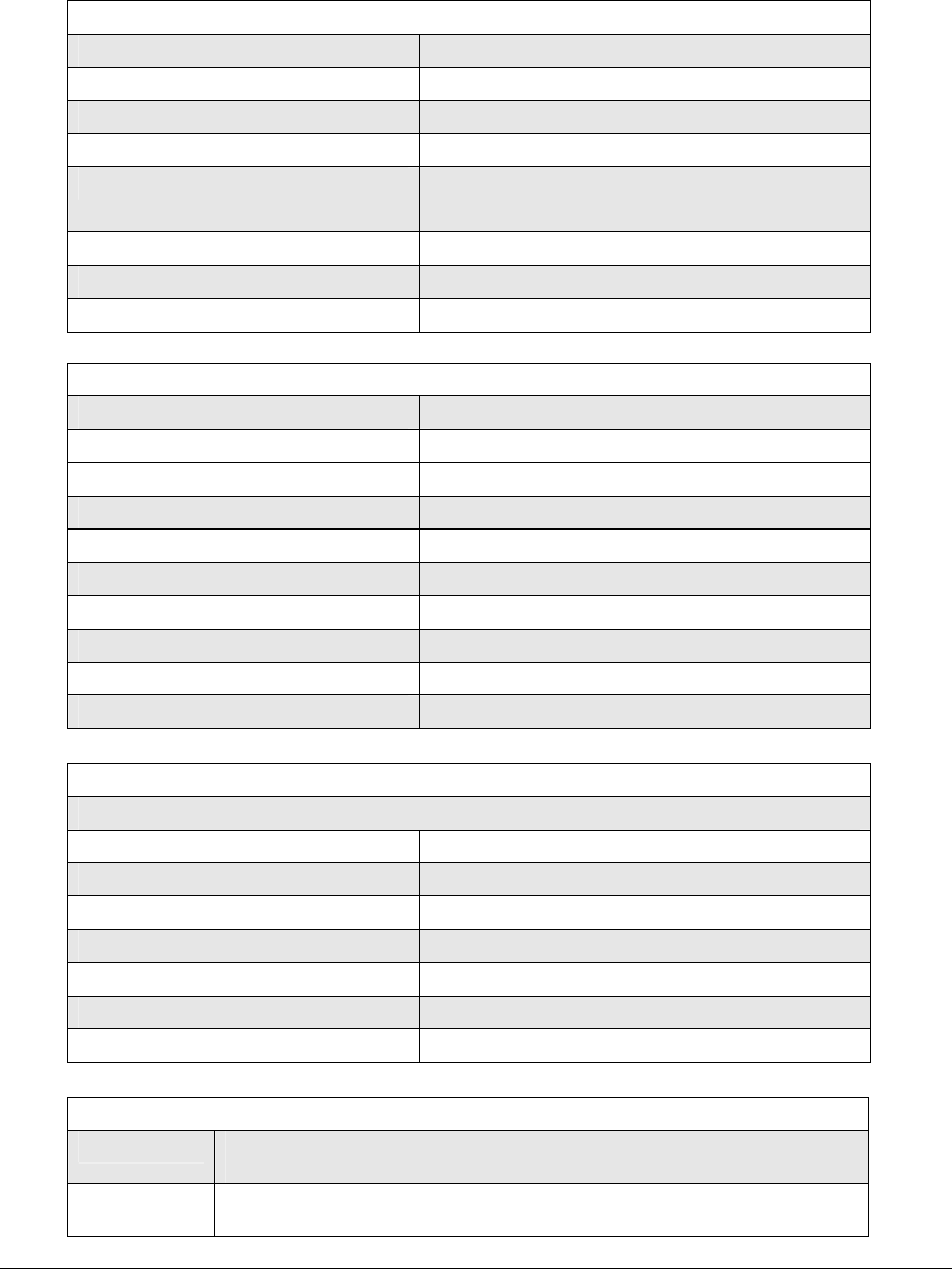
Lynx.GX and Tsunami Wireless Radio Installation and Maintenance
Lynx.GX 8T (ISM) Specifications
Product Information
Product Name Lynx.GX 8T1
Product Part Number 51145-10L0, -10H0
Frequency Band of Operation 5.725 to 5.850 MHz
Digital Capacity 8 x T1 (8 x 1.544 Mbps)
Frequency Channels A1: 5734 MHz A2: 5819 MHz
B1: 5756 MHz B2: 5841 MHz
T/R Spacing 85 MHz
Regulatory Compliance Part 15.247 (ISM)
FCC ID HZB-US5358-GX1
System and Transceiver Specifications
Frequency Range 5.725 – 5.850 GHz
Modulation type QPSK
System Gain 109 dB
Aggregate Data Rate 13.5 Mb/sec
Transmit Output Power +20 dBm minimum, +23 dBm typical
RF Transmit Power Range 20 dB
Transmit Frequency Stability ± 5 ppm
Receive Threshold at 10-6 BER -86 dBm
Maximum Receive Level -20 dBm error free, 0 dBm without damage
FEC T=4, Reed Solomon decoding
Digital Interface
Main Line Interface
Interface DSX-1 (T1)
Line Rate 8 x 1.544 Mbps
Connector(s) 8 x RJ-48C
Line Code AMI or B8ZS, selectable
Line Buildout 0 to 655 ft, selectable
Blue Code AIS (Alarm Indication Signal)
Regulatory Compliance ANSI-T1-102-1987
Front Panel LEDs
Data Loss Red = Any of the 8 T1 data ports has experienced a data signal loss
Off = None of the 8 T1 ports has experienced a data signal loss
AIS Out Green = AIS output enabled, when data loss has been detected
Yellow = AIS output enabled, loss of RF link detected
Appendix C. Technical Specifications C-85
CPN 62140 12/01/02

Lynx.GX and Tsunami Wireless Radio Installation and Maintenance
Off = AIS output not enabled (no data loss has been detected)
Appendix C. Technical Specifications C-86
CPN 62140 12/01/02

Lynx.GX and Tsunami Wireless Radio Installation and Maintenance
Lynx.GX 8E ISM Specifications
Product Information
Product Name Lynx.GX 8E1
Product Part Number 51145-20H0, -20L0
Frequency Band of Operation 5.725 to 5.850 MHz
Digital Capacity 16.384 Mbps (8 x E1)
Frequency Channels A1: 5745 MHz A2: 5831 MHz
T/R Spacing 85 MHz
Regulatory Compliance Part 15.247 (ISM)
FCC ID HZB-US5358-GX1
System and Transceiver Specifications
Frequency Range 5.750 – 5.850 GHz
Modulation type QPSK
System Gain 106 dB
Aggregate Data Rate 27.5 Mb/sec
Transmit Output Power +20 dBm minimum, +23 dBm typical
RF Transmit Power Range 20 dB
Transmit Frequency Stability ± 5 ppm
Receive Threshold at 10-6 BER -83 dBm
Maximum Receive Level -20 dBm error free, 0 dBm without damage
FEC T=4, Reed Solomon decoding
Digital Interface
Main Line Interface
Interface CEPT-1 (E1)
Line Rate 8 x 2.044 Mbps
Connector(s) 8 x RJ-48C
Line Code HDB3
Blue Code AIS (Alarm Indication Signal)
Regulatory Compliance ITU-T G.703
Front Panel LEDs
Data Loss Red = Any of the 8 E1 data ports has experienced a data signal loss
Off = None of the 8 E1 ports has experienced a data signal loss
AIS Out Green = AIS output enabled, when data loss has been detected
Yellow = AIS output enabled, loss of RF link detected
Off = AIS output not enabled (no data loss has been detected)
Appendix C. Technical Specifications C-87
CPN 62140 12/01/02
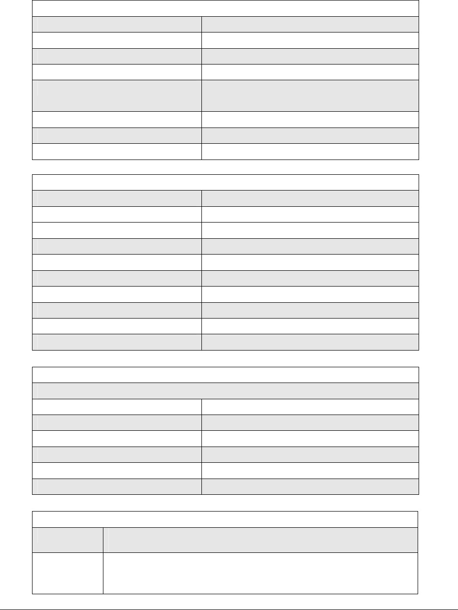
Lynx.GX and Tsunami Wireless Radio Installation and Maintenance
Lynx.GX 8E (U-NII) Specifications
Product Information
Product Name Lynx.GX 8E1
Product Part Number 51155-20H0, -20L0
Frequency Band of Operation 5.725 to 5.850 MHz
Digital Capacity 16.384 Mbps (8 x E1)
Frequency Channels A1: 5741.5 MHz A2: 5793.5 MHz
B1: 5756.5 MHz B2: 5808.5 MHz
T/R Spacing 52 MHz
Regulatory Compliance Part 15.407 (UNII)
FCC ID HZB-US5358-GX1
System and Transceiver Specifications
Frequency Range 5.725 – 5.825 GHz
Modulation type QPSK
System Gain 103 dB
Aggregate Data Rate 18 Mb/sec
Transmit Output Power +20 dBm minimum, +23 dBm typical
RF Transmit Power Range 20 dB
Transmit Frequency Stability ± 5 ppm
Receive Threshold at 10-6 BER -83 dBm
Maximum Receive Level -20 dBm error free, 0 dBm without damage
FEC T=8, Reed Solomon decoding
Digital Interface
Main Line Interface
Interface CEPT-1 (E1)
Line Rate 8 x 2.044 Mbps
Connector(s) 8 x RJ-48C
Line Code HDB3
Blue Code AIS (Alarm Indication Signal)
Regulatory Compliance ITU-T G.703
Front Panel LEDs
Data Loss Red = Any of the 8 E1 data ports has experienced a data signal loss
Off = None of the 8 E1 ports has experienced a data signal loss
AIS Out Green = AIS output enabled, when data loss has been detected
Yellow = AIS output enabled, loss of RF link detected
Off = AIS output not enabled (no data loss has been detected)
Appendix C. Technical Specifications C-88
CPN 62140 12/01/02
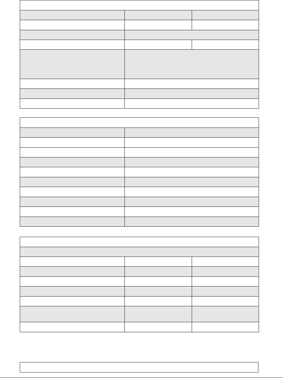
Lynx.GX and Tsunami Wireless Radio Installation and Maintenance
Lynx.GX 4T1 and Lynx.GX 4E1 (ISM) Specifications
Product Information
Product Name Lynx.GX 4T1 Lynx.GX 4E1
Product Part Number 51850-10L0, -10H0 51850-20L0, -20H0
Frequency Band of Operation 5.725 to 5.850 MHz
Digital Capacity 4 x T1 (4 x 1.544 Mbps) 4 x E1 (4 x 2.048 Mbps)
Frequency Channels A1: 5731.5 MHz A2: 5816.5 MHz
B1: 5745 MHz B2: 5830 MHz
C1: 5758.5 MHz C2: 5843.5 MHz
T/R Spacing 85 MHz
Regulatory Compliance Part 15.247 (ISM)
FCC ID HZB-US5358-GX1
System and Transceiver Specifications
Frequency Range 5.250 – 5.350 GHz, 5.725 – 5.850 GHz
Modulation type QPSK
System Gain 112 dB
Aggregate Data Rate 9 Mb/sec
Transmit Output Power +20 dBm minimum, +24 dBm typical
RF Transmit Power Range 20 dB
Transmit Frequency Stability ± 5 ppm
Receive Threshold at 10-6 BER -88 dBm
Maximum Receive Level -20 dBm error free, 0 dBm without damage
FEC T=4, Reed Solomon decoding
Digital Interface
Main Line Interface
Interface DSX-1 (T1) CEPT-1 (E1)
Line Rate 4 x 1.544 Mbps 4 x 2.048 Mbps
Connector(s) 4 x RJ-48C 4 x RJ-48C
Line Code AMI or B8ZS, selectable HDB3
Line Buildout 0 to 655 ft, selectable N/A
Blue Code AIS (Alarm Indication
Signal)
AIS (Alarm Indication
Signal)
Regulatory Compliance ANSI-T1-102-1987 ITU-T G.703
Front Panel LEDs
Appendix C. Technical Specifications C-89
CPN 62140 12/01/02

Lynx.GX and Tsunami Wireless Radio Installation and Maintenance
Data Loss Red = Any of the 4 T1 or 4 E1 data ports has experienced a data signal loss
Off = None of the 4 T1 or 4 E1 ports has experienced a data signal loss
AIS Out Green = AIS output enabled, when data loss has been detected
Yellow = AIS output enabled, loss of RF link detected
Off = AIS output not enabled (no data loss has been detected)
Appendix C. Technical Specifications C-90
CPN 62140 12/01/02
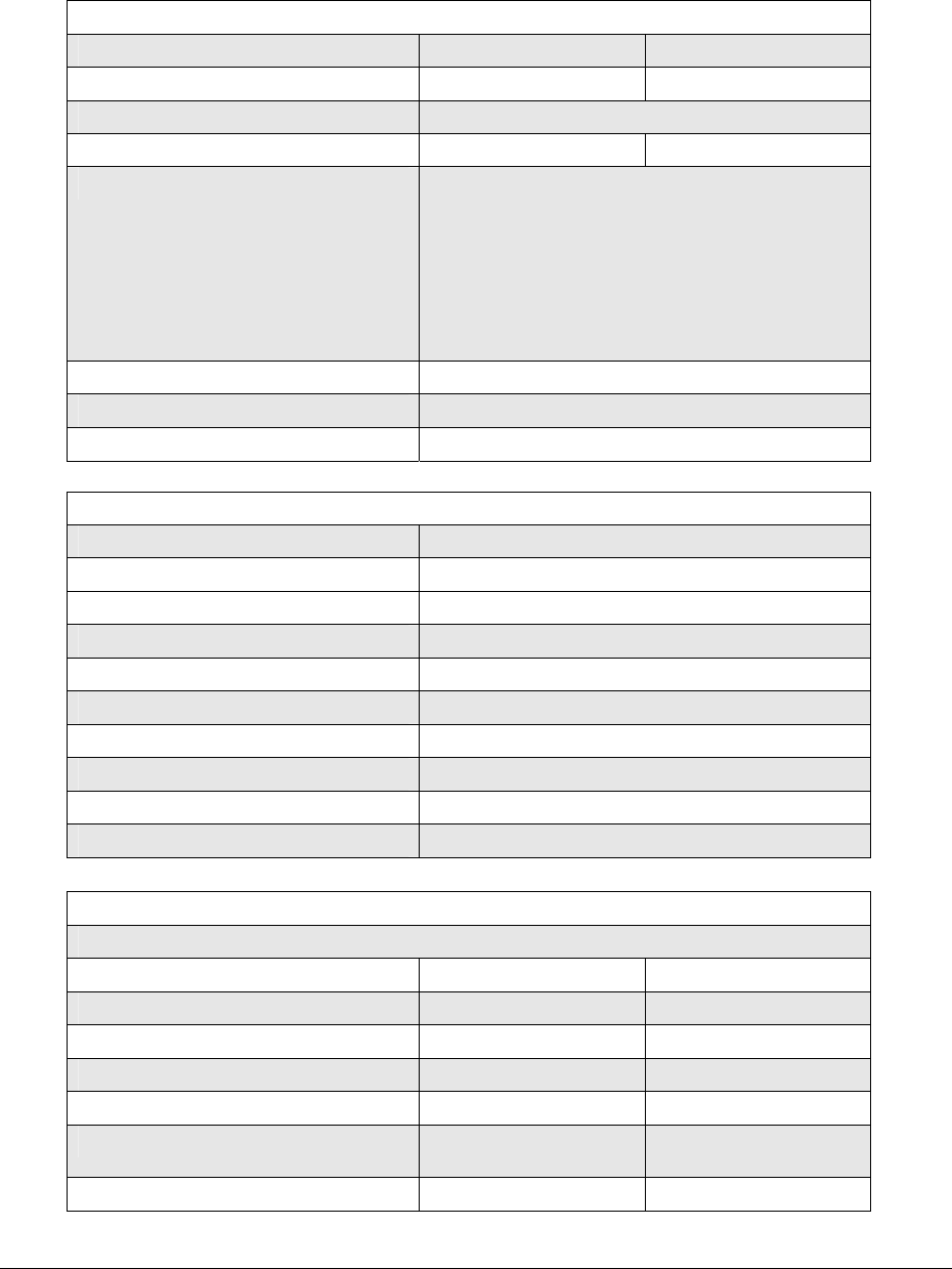
Lynx.GX and Tsunami Wireless Radio Installation and Maintenance
Lynx.GX 2T1 and Lynx.GX 2E1 (ISM) Specifications
Product Information
Product Name Lynx.GX 2T1 Lynx.GX 2E1
Product Part Number 51600-10L0, -10H0 51700--20L0, -20H0
Frequency Band of Operation 5.725 to 5.850 MHz
Digital Capacity 2 x T1 (2 x 1.544 Mbps) 2 x E1 (2 x 2.048 Mbps)
Frequency Channels A1: 5728.5 MHz A2: 5813.5 MHz
B1: 5735 MHz B2: 5820 MHz
C1: 5741.5 MHz C2: 5826.5 MHz
D1: 5748 MHz D2: 5833 MHz
E1: 5754.5 MHz E2: 5839.5 MHz
F1: 5761.0 MHz F2: 5846 MHz
T/R Spacing 85 MHz
Regulatory Compliance Part 15.247 (ISM)
FCC ID HZB-US5358-GX1
System and Transceiver Specifications
Frequency Range 5.250 – 5.350 GHz, 5.725 – 5.850 GHz
Modulation type QPSK
System Gain 115 dB
Aggregate Data Rate 4.5 Mb/sec
Transmit Output Power +20 dBm minimum, +24 dBm typical
RF Transmit Power Range 20 dB
Transmit Frequency Stability ± 5 ppm
Receive Threshold at 10-6 BER -91 dBm
Maximum Receive Level -20 dBm error free, 0 dBm without damage
FEC T=4, Reed Solomon decoding
Digital Interface
Main Line Interface
Interface DSX-1 (T1) CEPT-1 (E1)
Line Rate 2 x 1.544 Mbps 2 x 2.048 Mbps
Connector(s) 2 x RJ-48C 2 x RJ-48C
Line Code AMI or B8ZS, selectable HDB3
Line Buildout 0 to 655 ft, selectable N/A
Blue Code AIS (Alarm Indication
Signal)
AIS (Alarm Indication
Signal)
Regulatory Compliance ANSI-T1-102-1987 ITU-T G.703
Appendix C. Technical Specifications C-91
CPN 62140 12/01/02

Lynx.GX and Tsunami Wireless Radio Installation and Maintenance
Front Panel LEDs
Data Loss Red = Any of the 2 T1 or 2 E1 data ports has experienced a data signal loss
Off = None of the 2T1 or 2 E1 ports has experienced a data signal loss
AIS Out Green = AIS output enabled, when data loss has been detected
Yellow = AIS output enabled, loss of RF link detected
Off = AIS output not enabled (no data loss has been detected)
Appendix C. Technical Specifications C-92
CPN 62140 12/01/02
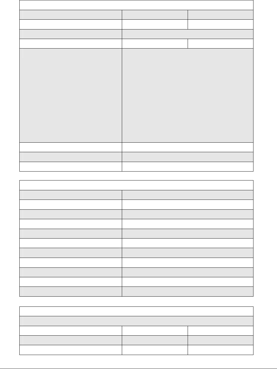
Lynx.GX and Tsunami Wireless Radio Installation and Maintenance
Lynx.GX T1 and Lynx.GX E1 (ISM) Specifications
Product Information
Product Name Lynx.GX T1 Lynx.GX E1
Product Part Number 51000-L0, -H0 51400-L0, -H0
Frequency Band of Operation 5.725 to 5.850 MHz
Digital Capacity 1 x T1 (1 x 1.544 Mbps) 1 x E1 (1 x 2.048 Mbps)
Frequency Channels A1: 5727 MHz A2: 5812 MHz
B1: 5731 MHz B2: 5816 MHz
C1: 5735 MHz C2: 5820 MHz
D1: 5739 MHz D2: 5824 MHz
E1: 5743 MHz E2: 5828 MHz
F1: 5747MHz F2: 5832 MHz
G1: 5751 MHz G2: 5836 MHz
H1: 5755 MHz H2: 5840 MHz
J1: 5759 MHz J2: 5844 MHz
K1: 5763 MHz K2: 5848 MHz
T/R Spacing 85 MHz
Regulatory Compliance Part 15.247 (ISM)
FCC ID HZB-US5358-GX1
System and Transceiver Specifications
Frequency Range 5.250 – 5.350 GHz, 5.725 – 5.850 GHz
Modulation type QPSK
Emission Bandwidth 2.7 MHz per channel (-6 dB)
System Gain 116 dB
Aggregate Data Rate 2.7 Mb/sec
Transmit Output Power +20 dBm minimum, +24 dBm typical
RF Transmit Power Range 20 dB
Transmit Frequency Stability ± 5 ppm
Receive Threshold at 10-6 BER -93 dBm
Maximum Receive Level -20 dBm error free, 0 dBm without damage
FEC T=4, Reed Solomon decoding
Digital Interface
Main Line Interface
Interface DSX-1 (T1) CEPT-1 (E1)
Line Rate 1 x 1.544 Mbps 1 x 2.048 Mbps
Connector 1 x RJ-48C 1 x RJ-48C
Appendix C. Technical Specifications C-93
CPN 62140 12/01/02

Lynx.GX and Tsunami Wireless Radio Installation and Maintenance
Line Code AMI or B8ZS, selectable HDB3
Line Buildout 0 to 655 ft, selectable N/A
Blue Code AIS (Alarm Indication
Signal)
AIS (Alarm Indication
Signal)
Regulatory Compliance ANSI-T1-102-1987 ITU-T G.703
Front Panel LEDs
Data Loss Red = Any T1 or E1 data ports has experienced a data signal loss
Off = No T1 or E1 ports has experienced a data signal loss
AIS Out Green = AIS output enabled, when data loss has been detected
Yellow = AIS output enabled, loss of RF link detected
Off = AIS output not enabled (no data loss has been detected)
Appendix C. Technical Specifications C-94
CPN 62140 12/01/02

Lynx.GX and Tsunami Wireless Radio Installation and Maintenance
Lynx.GX DS-3 (U-NII 5.3 GHz) Specifications
Product Information
Product Name Lynx.GX DS-3
Product Part Number 57750-91L0, -91H0
Frequency Band of Operation 5.250 to 5.350 MHz
Digital Capacity 44.736 Mbps
Frequency Channels A1: 5274 MHz A2: 5326 MHz
T/R Spacing 52 MHz
Regulatory Compliance Part 15.407 (U-NII)
FCC ID HZB-US5358-GX1
System and Transceiver Specifications
Frequency Range 5.250 – 5.350 GHz
Modulation type QPSK
System Gain 96 dB
Aggregate Data Rate 54 Mb/sec
Transmit Output Power +17 dBm minimum, +20 dBm typical
RF Transmit Power Range 20 dB
Transmit Frequency Stability ± 5 ppm
Receive Threshold at 10-6 BER -80 dBm
Maximum Receive Level -20 dBm error free, 0 dBm without damage
FEC T=4, Reed Solomon decoding
Digital Interface
Main Line Interface
Interface CEPT-1 (E1)
Line Rate 1 x 2.048 Mbps
Connector(s) 1 x RJ-48C
Line Code HDB3
Line Buildout N/A
Blue Code AIS (Alarm Indication Signal)
Regulatory Compliance ITU-T G.703
Wayside Line Interface
Interface CEPT-1 (E1)
Line Rate 1 x 2.048 Mbps
Connector(s) 1 x RJ-48C
Line Code HDB3
Line Buildout N/A
Appendix C. Technical Specifications C-95
CPN 62140 12/01/02

Lynx.GX and Tsunami Wireless Radio Installation and Maintenance
Blue Code AIS (Alarm Indication Signal)
Regulatory Compliance ITU-T G.703
Front Panel LEDs
Data Loss Red = Any of the 21 E1 data ports has experienced a data signal loss
Off = None of the 21 E1 ports has experienced a data signal loss
AIS Out Green = AIS output enabled, when data loss has been detected
Yellow = AIS output enabled, loss of RF link detected
Off = AIS output not enabled (no data loss has been detected)
Appendix C. Technical Specifications C-96
CPN 62140 12/01/02
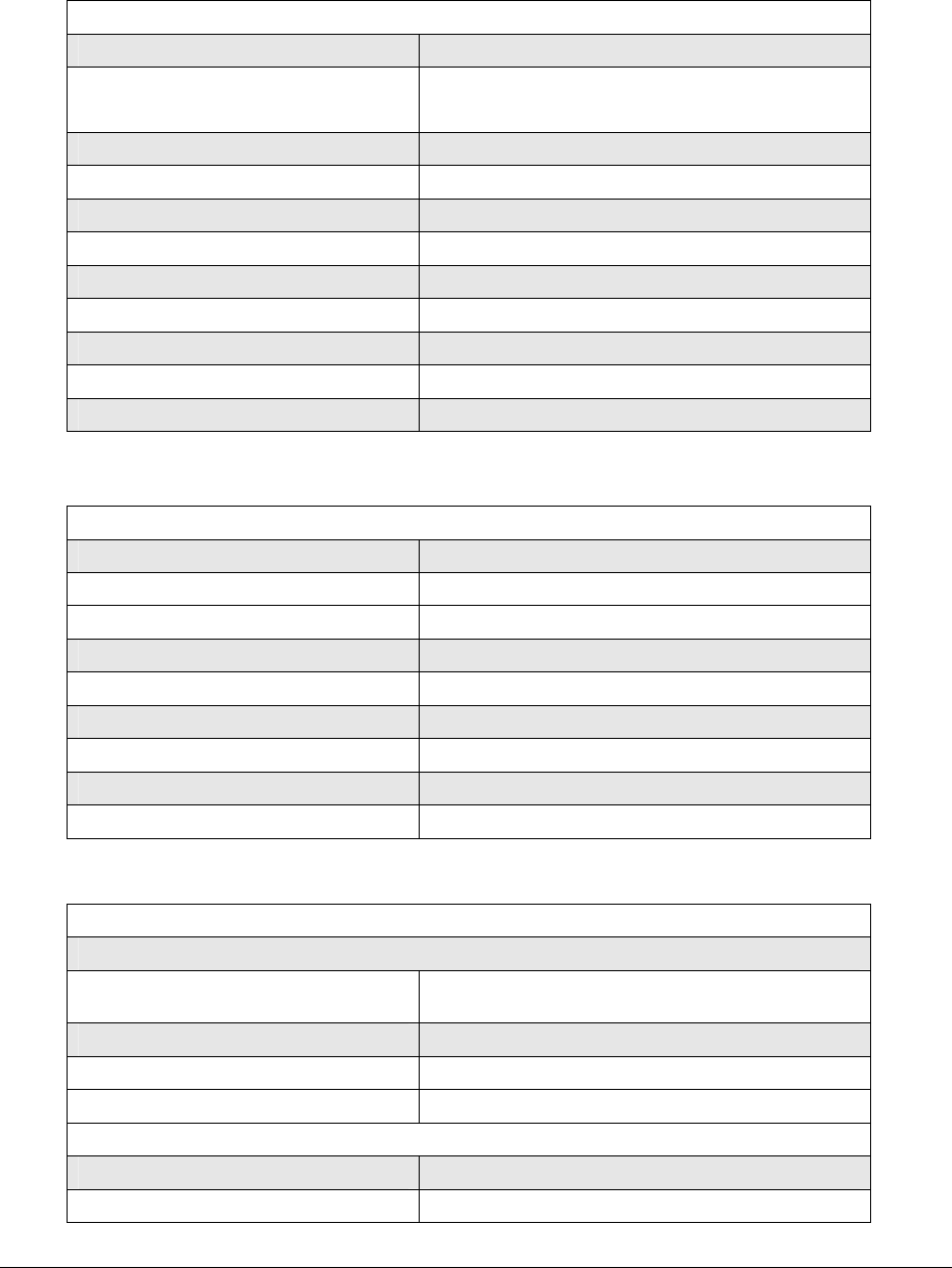
Lynx.GX and Tsunami Wireless Radio Installation and Maintenance
Tsunami General Specifications
General System Parameters
Operating Frequency 5.3 – 5.8 GHz
Product Configuration
1+0
IDU + RF Unit (RFU with outdoor option)
Digital Capacity 1.544 Mbps (T1) to 44.564 Mbps (DS-3)
Intermediate Frequency 749 MHz, 140 MHz (+/- 2 Mhz)
Digital Interface 10/100BaseTx
Error Floor 10-11
Latency (msec) <500 usec
Error Correction FEC, Reed-Solomon Decoding
Security 12 character Link ID code
Regulatory Compliance Part 15.407 U-NII
FCC ID HZB –US5358-GX1
Transceiver Specifications
Frequency Range 5.250 – 5.350 GHz, 5.725 – 5.850 GHz
Modulation type QPSK
System Gain See Unit specifications
Aggregate Data Rate See unit specifications
Transmit Output Power See Unit specifications
RF Transmit Power Range 20 dB
Transmit Frequency Stability ± 5 ppm
Receive Threshold at 10-6 BER See Unit specifications
Maximum Receive Level -20 dBm error free, 0 dBm without damage
Digital Interface (on IDU)
Main Line Interface
Interface 10/100BaseTx for RJ-45; 100BaseFx for ST fiber
connector
Line Rate 20 Mbps up to 90 Mbps, full duplex
Connector(s) 1 x RJ-48C; 1 x ST fiber
Regulatory Compliance IEEE 802.3d
Wayside Channel
Interface DSX-1 (T1)
Connector RJ-48C, modular jack
Appendix C. Technical Specifications C-97
CPN 62140 12/01/02

Lynx.GX and Tsunami Wireless Radio Installation and Maintenance
Line Code AMI or B8ZS, selectable
Line Buildout 0 to 655 ft, selectable
Blue Code AIS (Alarm Indication Signal)
Regulatory Compliance ANSI-T1-102-1987
Orderwire (for DTMF Handset)
Connector 2-wire, 4-pin mod jack RJ-11
REN 1.0 dB
DTMF Tones Within ± 1.5% of nominal frequency (+0 to 6 dB)
Ringing Voltage 48 Vdc, typical
Address 00 to 99
VF (Orderwire Bridge)
Connector RJ-45 jack (4-wire); bridged to Orderwire RJ-11
Input Level 0 dBm
Output Level 0 dBm
Impedance 600 ohm balanced
Configuration Port
Connector DB-9 DTE (female, 9 pin D sub)
Protocol RS-232 (8 bit data, No Parity, 1 Stop Bit)
Data Rate 9.6 kbps
Auxiliary Data Port
Connector RJ-45 DCE (modular jack, unkeyed)
Protocol RS-232 (8 bit Data, No Parity, 1 Stop Bit)
Data Rate 2.4 kHz, 4.8 kHz, 9.6kHz, 19.2 kHz
Alarms Port
Connector DB-9 (male, 9 pin D sub)
Form C Relay (NO, NC) Summary Alarm, Out-of-Service Alarm
Test Points RSL and Tx power output (DC voltage)
Network Management System
Connector RJ-45 (modular jack, unkeyed) 2 each
NMS 1 10/100 Base-Tx (out-of-band)
NMS 2 100Base-Tx (in-band)
Interface (RF Unit)
Antenna Port
Connector Type-N female
Impedance 50 ohms
Signal See Unit Specifications for frequency channels
Appendix C. Technical Specifications C-98
CPN 62140 12/01/02

Lynx.GX and Tsunami Wireless Radio Installation and Maintenance
IF Port
Connector TNC female
Impedance 50 ohms
Signal Uplink: 749 MHz; Downlink: 140 MHz; +48Vdc
Output RSL
Connector BNC female, cap and chain
Output Level 0.5 to 3.0 Vdc corresponds to -90 to –20 dBm
500 Hz to 3 kHz for earphone jack
Audio Tone RSL and RSL earphone connectors are combined
onto single connector
Fault and Configuration Management
Type Integral SNMP Agent
Integral Web Server
Serial Craft Terminal CLI
Telnet, via 10/100BT
100 Base-Fx Ethernet port In-band
RJ-45 modular jack
Auto-negotiate duplex
10/100 Base-Tx Ethernet port Out-of-Band
RJ-45 modular jack
Auto-negotiate speed and duplex
Configuration port VT-100 Craft Terminal; 9-pin D sub; 9600 baud
SNMP SNMP v2, MIB II, Proxim Enterprise MIB
Network Element Managers HPOpenView or equivalent
SNMP Reports Alarm traps sent to up to 5 Managers; via MIB
variables
Web Browser Compatibility Any IE version above 5.0 (5.0, 5.5, 6.0)
Netscape 6.1 in both Windows and Linux
Netscape 6.21 in Windows
Not compatible: Netscape 6.21 in Linux
User Access Security Two level password protection
Performance Management ES, SES, BER, LOS; near and far end
Alarm Log up to 1000 entries
Software Updates Download via TFTP over Ethernet
Configuration Management Local end only, via IP address
Advanced features Spectrum Analyzer – 10 channels
RSL Time charting
Temperature and Environment
Operating Temperature, RF Unit -30° to +55° C
Operating Temperature, IDU 0° to +50° C
Humidity, IDU 95% max, non-condensing
Appendix C. Technical Specifications C-99
CPN 62140 12/01/02

Lynx.GX and Tsunami Wireless Radio Installation and Maintenance
Humidity, ODU 100%, all weather
Altitude 10,000 ft., maximum
Wind (RF unit) Up to 115 miles per hour
Compliance N/A
Power Requirements
VDC nominal input voltage (IDU) -48 Vdc or +24 Vdc
IDU DC Input Voltage Range (IDU) -20 to –63 Vdc or +20 to +63 Vdc
Power Consumption Per Terminal < 100 watts
Power Consumption IDU: < 60 watts; ODU: <40 watts
AC Adapter (external) for IDU 130 watts; 50/60 Hz, 110/220 VAC; -48 Vdc, 2A
DC Power Connector (IDU) 3-pin barrier strip type, plug-in
Connector (RF Unit) Uses coax cable for delivery
ODU voltage level +48 volts DC
Power delivery to ODU DC voltage over coax cable
Mechanical
IDU Size (w x h x d)
Weight
17.2 x 1.75 x 11 inch (1RU)
< 11 lbs
RF Unit Size (w x h x d)
Weight
14 x 1.75 x 11 inch (1RU)
< 13 lbs
Mounting IDU: EIA rack mount 19-inch rack mount; 23-inch
extenders in kit
RF Unit: EIA rack mount 19-inch rack mount; Pole-
mounted, 1.5 to 3 inch diameter pole using
mounting plate
Cooling IDU: 3 each DC fans
RF Unit: Heatsink
Cable Specifications
RF Cable to antenna
Cable type LMR-400, equivalent or better
Cable connector Type-N male
Impedance 50 ohm
IDU-RF Unit interconnection
Cable Type LMR-240 or equivalent for <100 meters
LMR-400 or equivalent for <300 meters
Cable Connector TNC male
Impedance 50 ohm
Regulatory Information
FCC Rules Part 15.247 ISM; 15.407 U-NII
Industry Canada Requirements IC RSS210
UL and Safety N/A
Appendix C. Technical Specifications C-100
CPN 62140 12/01/02
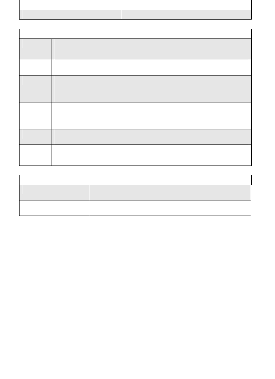
Lynx.GX and Tsunami Wireless Radio Installation and Maintenance
IDU Controls
Far End Pushbutton Yes
Front Panel LEDs
IDU Green = Indoor Unit OK
Yellow = Warning condition in IDU (over-temp or both fans failed)
Red = All fans failed, over-temp (> 55°C), or NMU/IDU communication failure
Cable Green = ODU Cable OK
Red = ODU Cable shorted
ODU Green = Outdoor Unit OK
Red = Over-temp (>65°C), IDU to ODU communication failure, DC power loss,
or Outdoor Unit detected hardware failure
Yellow = Over temperature alarm, exceeds 60°C
RF Link Green = Link established with BER <10E-6
Yellow = BER ≥ 10E-6; any bit errors due to FEC overload
Red = BER > 10E-3 or Loss of Sync
Blinking Red = Link ID does not match with far end ratio
Loopback Flashing Yellow = Loopback service is enabled
Solid Yellow = Internal signal generator turned on and errors detected online
NMS
(10/100
Base-T)
Green = Tx or Rx data present on the NMS interface (handshaking is occurring)
Off = No NMS data, interface connection detected
NMS Connector LEDs
10/100 Base-Tx NMS Link: Green = Link On; Off = Link Off
Duplex: Green = Full/Auto; Off = Half Duplex
100 Base-Tx Link: Green = Link On; Off = Link Off
Duplex: Green = Full/Auto; Off = Half Duplex
Appendix C. Technical Specifications C-101
CPN 62140 12/01/02
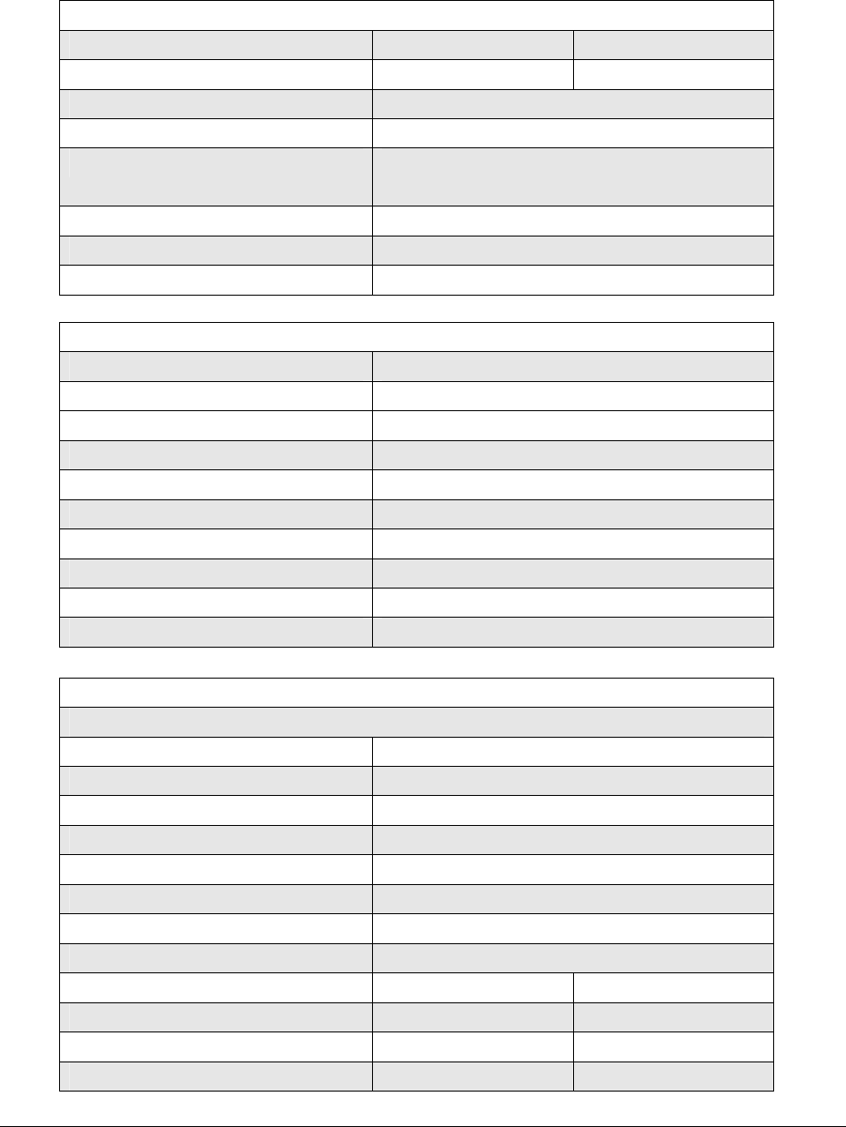
Lynx.GX and Tsunami Wireless Radio Installation and Maintenance
Tsunami 20 + 2T1 and Tsunami 20 + 2E1 Specifications
Product Information
Product Name Tsunami 20 +2 T1 Tsunami 20 +2E1
Product Part Number 51145-41H0, -41L0 51145-42H0, -42L0
Frequency Band of Operation 5.725 to 5.850 MHz
Digital Capacity 10 Mbps
Frequency Channels A1: 5734 MHz A2: 5819 MHz
B1: 5756 MHz B2: 5841 MHz
T/R Spacing 85 MHz
Regulatory Compliance Part 15.247 (ISM)
FCC ID HZB-US5358-GX1
System and Transceiver Specifications
Frequency Range 5.725 – 5.850 GHz
Modulation type QPSK
System Gain 109 dB
Aggregate Data Rate 13.5 Mb/sec
Transmit Output Power +20 dBm minimum, +23 dBm typical
RF Transmit Power Range 20 dB
Transmit Frequency Stability ± 5 ppm
Receive Threshold at 10-6 BER -86 dBm
Maximum Receive Level -20 dBm error free, 0 dBm without damage
FEC T=4, Reed Solomon decoding
Digital Interface
Main Line Interface
Interface 10/100BaseTx
Line Rate 20 Mbps (10 Mbps full duplex)
Connector(s) 1 x RJ-48C, 1 x ST (fiber)
Line Code N/A
Line Buildout N/A
Blue Code N/A
Regulatory Compliance IEEE 802.3d
Wayside Line Interface
Interface DSX-1 (T1) CEPT-1 (E1)
Line Rate 2x 1.544 Mbps 2 x 2.048 Mbps
Connector(s) 2 x RJ-48C 2 x RJ-48C
Line Code AMI or B8ZS, selectable HDB3
Appendix C. Technical Specifications C-102
CPN 62140 12/01/02

Lynx.GX and Tsunami Wireless Radio Installation and Maintenance
Line Buildout 0 to 655 ft, selectable N/A
Blue Code AIS (Alarm Indication
Signal)
AIS (Alarm Indication
Signal)
Regulatory Compliance ANSI-T1-102-1987 ITU-T G.703
Front Panel LEDs
Data Loss Red = 10/100BT port has experienced a data signal loss
Off = 10/100BT port has not experienced a data signal loss
AIS Out Green = AIS output enabled, when data loss has been detected
Yellow = AIS output enabled, loss of RF link detected
Off = AIS output not enabled (no data loss has been detected)
Appendix C. Technical Specifications C-103
CPN 62140 12/01/02

Lynx.GX and Tsunami Wireless Radio Installation and Maintenance
Tsunami 90 +2T1 and Tsunami 90 +2E1 (U-NII 5.8 GHz) Specifications
Product Information
Product Name Tsunami 90 +2T1 Tsunami 90 +2E1
Product Part Number 57710-51L0, -51H0 57710-52L0, -52H0
Frequency Band of Operation 5.725 to 5.825 MHz
Digital Capacity 44.736 Mbps 44.736 Mbps
Frequency Channels A1: 5749 MHz A2: 5801 MHz
T/R Spacing 52 MHz
Regulatory Compliance Part 15.407 (U-NII)
FCC ID HZB-US5358-GX1
System and Transceiver Specifications
Frequency Range 5.725 – 5.825 GHz
Modulation type QPSK
System Gain 100 dB
Aggregate Data Rate 54 Mb/sec
Transmit Output Power +17 dBm minimum, +20 dBm typical
RF Transmit Power Range 20 dB
Transmit Frequency Stability ± 5 ppm
Receive Threshold at 10-6 BER -80 dBm
Maximum Receive Level -20 dBm error free, 0 dBm without damage
FEC T=4, Reed Solomon decoding
Digital Interface
Main Line Interface
Interface 100BaseTx 100BaseTx
Line Rate 90 Mbps (45 Mbps full
duplex)
90 Mbps (45 Mbps full
duplex)
Connector(s) 1 x RJ-48C, 1 x ST
(fiber)
1 x RJ-48C, 1 x ST
(fiber)
Line Code N/A N/A
Line Buildout N/A N/A
Blue Code N/A N/A
Regulatory Compliance IEEE 802.3d IEEE 802.3d
Wayside Line Interface
Interface DSX-1 (T1) CEPT-1 (E1)
Line Rate 2 x 1.544 Mbps 2 x 2.048 Mbps
Connector(s) 2 x RJ-48C 2 x RJ-48C
Line Code AMI or B8ZS, selectable HDB3
Appendix C. Technical Specifications C-104
CPN 62140 12/01/02

Lynx.GX and Tsunami Wireless Radio Installation and Maintenance
Line Buildout 0 to 655 ft, selectable N/A
Blue Code AIS (Alarm Indication
Signal)
AIS (Alarm Indication
Signal)
Regulatory Compliance ANSI-T1-102-1987 ITU-T G.703
Front Panel LEDs
Data Loss Red = 100BaseTx port has experienced a data signal loss
Off = 100BaseTx port has not experienced a data signal loss
AIS Out Green = AIS output enabled, when data loss has been detected
Yellow = AIS output enabled, loss of RF link detected
Off = AIS output not enabled (no data loss has been detected)
Appendix C. Technical Specifications C-105
CPN 62140 12/01/02

Lynx.GX and Tsunami Wireless Radio Installation and Maintenance
Tsunami 90 +2T1 and Tsunami 90 +2E1 (U-NII 5.3 GHz) Specifications
Product Information
Product Name Tsunami 90 +2T1 Tsunami 90 +2E1
Product Part Number 57750-51L0, -51H0 57750-52L0, -52H0
Frequency Band of Operation 5.250 to 5.350 MHz
Digital Capacity 44.736 Mbps 44.736 Mbps
Frequency Channels A1: 5274 MHz A2: 5326 MHz
T/R Spacing 52 MHz
Regulatory Compliance Part 15.407 (U-NII)
FCC Emission Designator HZB-US5358-GX1
System and Transceiver Specifications
Frequency Range 5.250 – 5.350 GHz
Modulation type QPSK
System Gain 96 dB
Aggregate Data Rate 54 Mb/sec
Transmit Output Power +17 dBm minimum, +20 dBm typical
RF Transmit Power Range 20 dB
Transmit Frequency Stability ± 5 ppm
Receive Threshold at 10-6 BER -78 dBm
Maximum Receive Level -20 dBm error free, 0 dBm without damage
FEC T=4, Reed Solomon decoding
Digital Interface
Main Line Interface
Interface 100BaseTx 100BaseTx
Line Rate 90 Mbps (45 Mbps full
duplex)
90 Mbps (45 Mbps full
duplex)
Connector(s) 1 x RJ-48C, 1 x ST
(fiber)
1 x RJ-48C, 1 x ST
(fiber)
Line Code N/A N/A
Line Buildout N/A N/A
Blue Code N/A N/A
Regulatory Compliance IEEE 802.3d IEEE 802.3d
Wayside Line Interface
Interface DSX-1 (T1) CEPT-1 (E1)
Line Rate 2 x 1.544 Mbps 2 x 2.048 Mbps
Connector(s) 1 x RJ-48C 1 x RJ-48C
Line Code AMI or B8ZS, selectable HDB3
Appendix C. Technical Specifications C-106
CPN 62140 12/01/02

Lynx.GX and Tsunami Wireless Radio Installation and Maintenance
Line Buildout 0 to 655 ft, selectable N/A
Blue Code AIS (Alarm Indication
Signal)
AIS (Alarm Indication
Signal)
Regulatory Compliance ANSI-T1-102-1987 ITU-T G.703
Front Panel LEDs
Data Loss Red = 100BaseTx port has experienced a data signal loss
Off = 100BaseTx port has not experienced a data signal loss
AIS Out Green = AIS output enabled, when data loss has been detected
Yellow = AIS output enabled, loss of RF link detected
Off = AIS output not enabled (no data loss has been detected)
Appendix C. Technical Specifications C-107
CPN 62140 12/01/02

Lynx.GX and Tsunami Radio Installation and Configuration
Warranty
GENERAL TERMS #) and the address of the location to which the
Customer may ship the defective item;
1.1 All Definitions contained in Proxim's Conditions of Sale
(Proxim document number CS96-8), apply to the (c) if the problem is not resolved over the telephone, the
Warranty. Customer shall attach a label to each Returned item
describing the fault and the Customer's Return
1.2 Subject to the provisions of the Warranty, Proxim address. The Customer shall, at its cost, properly pack
warrants that the equipment described in Paragraph 1.3 the item to be Returned, prepay the insurance and
shall conform to their specifications described in shipping charges, and ship the item to the specified
Paragraph 1.4 in all material respects and that the location;
equipment shall be free from material defects in materials
and workmanship. (d) if the Proxim product shall prove to be defective in
material or workmanship upon examination by
1.3 This Warranty applies to all original purchases of Proxim, Proxim shall either repair or replace the
Proxim manufactured equipment and accessories Returned item at its sole option. The replacement item
(collectively the "Equipment"). may be new or refurbished; if refurbished, it shall be
equivalent in operation to new Equipment. If a
1.4 This Warranty applies to the specifications contained in Returned item is replaced by Proxim, the Customer
the most recent version of the manual for the model of agrees that the Returned item shall become the
the Equipment purchased (the "Specifications"). property of Proxim.
1.5 This Warranty does not apply to the following items of (e) Proxim shall at its cost, ship the repaired item or
Equipment which are covered by the Original Equipment replacement to any destination within the United
Manufacturer's warranty: States of America by carrier and method of delivery
chosen by Proxim. If the Customer has requested
(a) antenna systems, including coax cable, waveguide, some other form of conveyance, such as express
connectors flex-sections, mounts, other parts of the shipping, or is located beyond the USA borders, then
antenna system and installation materials; the Customer shall pay to the cost of return shipment.
(b) non-Proxim manufactured rack mounted equipment 2.2 Equipment which is repaired or replaced by Proxim
that is assembled wired and tested at Proxim's under this Warranty shall be covered under all of the
factory or supplied as part of a system, including provisions of this Warranty for the remainder of the
orderwire items, channel banks, multiplexers, applicable Warranty Period or ninety (90) days from the
fuse/alarm panels, remote alarm items; and date of shipment of the repaired item or replacement,
whichever period is longer.
(c) equipment which is not listed in Proxim's price book.
DEFAULT AND TERMINATION
1.6 The effective period of this Warranty shall start on the
date of shipment of the Equipment and shall end:
3.1 Proxim may immediately terminate this Warranty and all
of its performance under this Warranty, upon notification
(a) for all spread spectrum unlicensed radio products and
for all licensed digital microwave radio products, two to the Customer, if the Customer:
(2) years later;
(a) makes any unauthorized modifications to the
(b) for all analog microwave radio products, three (3) Equipment;
years later; or
(b) assigns or transfers the Customer's rights or
(c) for all baseband products, five (5) years later (in each obligations under this Warranty without the written
case the "Warranty Period"). consent of Proxim;
1.7 The Customer acknowledges that Proxim does not (c) becomes bankrupt or insolvent, or is put into
represent or warrant that the services provided by receivership; or
Proxim under this Warranty will ensure uninterrupted or
error-free operation of the Equipment. (d) has not paid Proxim all amounts for the Equipment,
services, or other additional charges within thirty (30)
RETURN OF EQUIPMENT UNDER WARRANTY days of receipt of written notice from Proxim.
2.1 If an item of Equipment malfunctions or fails in normal 3.2 If this Warranty is terminated by Proxim, the Customer
intended usage and maintenance within the applicable shall remain liable for all amounts due to Proxim.
Warranty Period:
FORCE MAJEURE
(a) the Customer shall promptly notify Proxim of the
problem and the serial number of the defective item; 4.1 "Force Majeure" has the same meaning as defined in
Proxim's Conditions of Sale (Proxim document
(b) Proxim shall, at its sole option, either resolve the number CS96-8).
problem over the telephone or provide the Customer
with a Returned Materials Authorization number (RMA 4.2 Proxim shall not be responsible for failure to discharge
Warranty Warranty-108
CPN 62140 12/01/02

Lynx.GX and Tsunami Wireless Radio Installation and Maintenance
its obligations under this Warranty due to Force Majeure. CLAIM AGAINST A CUSTOMER BY A THIRD PARTY;
OR ANY OTHER COMMERCIAL OR ECONOMIC
LIMITATIONS AND QUALIFICATIONS OF WARRANTY LOSSES OF ANY KIND.
5.1 This Warranty does not apply to any damage, defect or 6.4 THESE LIMITATIONS AND DISCLAIMERS ARE NOT
failure caused by: MADE BY PROXIM WHERE PROHIBITED BY LAW.
LIMITATIONS ON DAMAGES (International)
(a) any part of the Equipment having been modified,
adapted, repaired, or improperly installed, operated,
maintained, transported or relocated by any person other 6.1 THE WARRANTY STATED IN THIS DOCUMENT IS
than Proxim personnel or a Proxim authorized service THE CUSTOMER'S EXCLUSIVE WARRANTY FOR THE
agent, without Proxim's prior written consent; EQUIPMENT; ALL OTHER WARRANTIES OF ANY
KIND, EXPRESS OR IMPLIED, INCLUDING ANY
(b) storage or environmental conditions which do not WARRANTIES OF FITNESS FOR A PARTICULAR
conform to the applicable sections of the appropriate PURPOSE AND OF MERCHANTABILITY ARE
Proxim Equipment Manual; EXCLUDED TO THE FULLEST EXTENT PERMITTED
BY LAW.
(c) failure to conform with the Equipment Installation,
Operating and Maintenance Instructions of the 6.2 PROXIM'S LIABILITY FOR FAILURE TO FULFIL ITS
appropriate Proxim Equipment Manual; OBLIGATIONS UNDER THIS WARRANTY OR IN TORT
OR AS A RESULT OF STRICT LIABILITY OR ANY
(d) external causes, including external electrical stress or OTHER LIABILITY UNDER OR IN CONNECTION WITH
lightning, or use in conjunction with incompatible THE EQUIPMENT OR ITS SUPPLY SHALL BE
equipment, unless such use was with Proxim's prior LIMITED, EXCEPT IN RESPECT OF DEATH AND
written consent; PERSONAL INJURY CAUSED BY PROXIM'S
NEGLIGENCE, TO THE AMOUNT OF THE PURCHASE
(e) cosmetic damage; PRICE OF THE EQUIPMENT. THE REMEDIES
STATED IN THIS WARRANTY ARE THE CUSTOMER'S
(f) accidental damage, negligence, neglect, mishandling, EXCLUSIVE REMEDIES AGAINST PROXIM
abuse or misuse, other than by Proxim personnel or a REGARDING THE EQUIPMENT.
Proxim authorized service agent; or
6.3 EVEN IF PROXIM HAS BEEN ADVISED OF THE
(g) Force Majeure. POSSIBILITY OF THEM, PROXIM SHALL NOT BE
LIABLE FOR ANY INDIRECT, INCIDENTAL, SPECIAL
Please see reverse side for additional limitations on OR CONSEQUENTIAL DAMAGES, INCLUDING THE
damages. COST OF LABOR BY THE CUSTOMER'S OWN
EMPLOYEES, AGENTS OR CONTRACTORS IN
LIMITATIONS ON DAMAGES (North America) IDENTIFYING, REMOVING OR REPLACING THE
DEFECTIVE ITEM; LOST PROFITS, AND REVENUES;
6.1 THE WARRANTY STATED IN THIS DOCUMENT IS FAILURE TO REALIZE EXPECTED SAVINGS; ANY
THE CUSTOMER'S EXCLUSIVE WARRANTY FOR THE CLAIM AGAINST A CUSTOMER BY A THIRD PARTY;
EQUIPMENT; PROXIM SPECIFICALLY DISCLAIMS OR ANY OTHER COMMERCIAL OR ECONOMIC
ALL OTHER WARRANTIES OF ANY KIND, EXPRESS LOSSES OF ANY KIND.
OR IMPLIED, INCLUDING ANY WARRANTIES OF
DEFINITIONS
FITNESS FOR A PARTICULAR PURPOSE AND OF
MERCHANTABILITY. 1.1 In these Conditions, unless there is something in the
subject
6.2 PROXIM SHALL NOT BE LIABLE IN TORT, matter or context necessarily inconsistent:
INCLUDING LIABILITY IN NEGLIGENCE OR STRICT
LIABILITY, AND SHALL HAVE NO LIABILITY AT ALL (a) "Proxim" means Proxim Multiplex Corporation (d.b.a.
FOR INJURY TO PERSONS OR PROPERTY. Proxim Multiplex), Sunnyvale, CA;
PROXIM'S LIABILITY FOR FAILURE TO FULFIL ITS
OBLIGATIONS UNDER THIS WARRANTY OR ANY (b) "Equipment" means the equipment itemized on the
OTHER LIABILITY UNDER OR IN CONNECTION WITH Quotation/Order Acknowledgment;
THE EQUIPMENT SHALL BE LIMITED TO THE
AMOUNT OF THE PURCHASE PRICE OF THE (c) "International" means any location other than United
States
EQUIPMENT. THE REMEDIES STATED IN THIS
WARRANTY ARE THE CUSTOMER'S EXCLUSIVE of America and Canada, including their territories and
REMEDIES AGAINST PROXIM REGARDING THE possessions;
EQUIPMENT.
(d) "North America" means any location in the United States
of
6.3 EVEN IF PROXIM HAS BEEN ADVISED OF THE
POSSIBILITY OF THEM, PROXIM SHALL NOT BE America and Canada, including their territories and
LIABLE FOR ANY INDIRECT, INCIDENTAL, SPECIAL possessions;
OR CONSEQUENTIAL DAMAGES, INCLUDING THE
COST OF LABOR BY THE CUSTOMER'S OWN (e) "Order Acknowledgment" means the sales order
EMPLOYEES, AGENTS OR CONTRACTORS IN acknowledgment provided by Proxim to the Customer;
IDENTIFYING, REMOVING OR REPLACING THE
DEFECTIVE ITEM; LOST PROFITS, AND REVENUES; (f) "Payment Instructions" means Proxim's payment
FAILURE TO REALIZE EXPECTED SAVINGS; ANY instructions, (Proxim document P197-1);
Warranty Warranty-109
CPN 62140 12/01/02

Lynx.GX and Tsunami Wireless Radio Installation and Maintenance
(g) "Quotation" means the quotation signed by an
authorized representative of Proxim and provided to
the Customer;
(h) "Shipping Date" means the actual date on which the
Equipment left Proxim's factory at Sunnyvale, CA, U.S.A.;
(i) "Warranty" means Proxim's warranty, document W97-1;
(j) "Invoice" means the bill of goods prepared by Proxim for
the equipment with the shipping and any insurance costs.
1.2 Headings have been inserted in these Conditions for
convenience of reference only and will not effect their
construction.
ENTIRE AGREEMENT
2.1 The Quotation, these Conditions of Sale, the Order
Acknowledgment, the Payment Instructions and the
Warranty shall apply to all sales made by Proxim and shall
constitute the entire agreement by Proxim and the
Customer (the "Agreement ").
2.2 Any terms and/or conditions of sale, which may be
included on the Customer's purchase order form or any
communication from the Customer, that are not identical
with the terms and conditions steed in this document shall
NOT become a part of the agreement of sale unless
expressly agreed to in writing in the Quotation.
2.3 Proxim's failure to object to any terms and/or conditions
of sale contained in any communication from the Customer
shall not be considered as acceptance of such terms and/or
conditions or as a waiver of the terms and conditions of sale
contained herein.
2.4 Proxim shall sell to the Customer, and the Customer
shall purchase from Proxim, the Equipment in accordance
with the Agreement. Proxim accepts the Customer's
purchase orders for Equipment and agrees to deliver the
Equipment to the Customer only on the terms of the
Agreement.
2.5 No variation of the Agreement shall be binding unless
agreed to in writing by authorized representatives of Proxim
and the Customer.
PRICING
3.1 All prices in the Quotation are exclusive of all shipping
charges and all applicable taxes including but not limited to,
federal, state, local, excise, sales and use taxes.
3.2 All prices in the Quotation unless otherwise stated:
(a) for North American customers are FOB Sunnyvale, CA,
USA. (New York Uniform Commercial Code); or
(b) for international customers are Ex-Works, Sunnyvale,
CA, U.S.A. (Incoterms 1990).
3.3 All prices in the Quotation include standard domestic
packing, unless a separate line item is provided detailing
export or special packing charges.
SHIPPING AND INSURANCE
4.1 Proxim shall arrange shipping and insurance when
requested by the Customer, and shall bill the Customer for
the Equipment with the shipping and any insurance costs as
separate items, on an invoice (the "Invoice").
4.2 Delivery dates quoted by Proxim are to be considered
estimates only. In no event will Proxim be liable for any loss
or damage resulting from its failure to deliver products
within a specified time.
TERMS OF PAYMENT
5.1 The Customer shall pay for all Equipment, including
shipping and insurance in accordance with the terms of the
Invoice.
5.2 All Invoices for North American Customers are due and
payable in thirty (30) days from the date of the Invoice.
5.3 International Customers shall make payments in
accordance with Proxim's Payment Instructions by either:
(a) providing a wire transfer (telegraphic transfer) for the full
amount of the Equipment, shipping and insurance charges
contained in the Quotation or the pro-forma Invoice sent to
the Customer, prior to the Shipping Date; or
(b) establishing an acceptable Letter of Credit (LC) for the
full amount of the Equipment, shipping and insurance
charges contained in the Quotation prior to the order being
booked and accepted by Proxim.
5.4 If a Customer fails to pay an Invoice when due, Proxim
may, without prejudice to am other remedy, postpone
shipments, alter payment terms, terminate the Agreement
and charge interest on all overdue amounts the rate of 1.5%
per month compounded monthly (or if less, the maximum
allowed by law). Upon demand, the Customer shall pay all
such interest charges and all reasonable collection fees,
including reasonable legal expenses.
SECURITY FOR PAYMENT
6.1 If the Customer is located in North America, the
Customer grants to Proxim a purchase money security
interest in the Equipment to secure the payment of the
purchase price of the Equipment and all other amounts due
from the Customer.
6.2 If the Customer is not located in North America:
(a) despite delivery and passing of risk in the Equipment
and any other provision of these Conditions, the title in the
Equipment shall not pass to the Customer until Proxim has
received payment in full of the purchase price of the
Equipment and all other amounts then due from the
Customer, and (b) until the title in the Equipment passes to
the Customer:
(i) the Customer shall hold the equipment as Proxim 's
fiduciary agent and bailee, and shall properly store,
protect and insure the Equipment and shall identify the
Equipment as Proxim property;
(ii) if the Customer fails to pay Proxim in accordance with
the agreed payment terms, Proxim may require the
Customer to deliver up the Equipment to Proxim,
and, if the Customer does not, Proxim may enter on
the premises where the Equipment is stored and
repossess the Equipment; and
(iii) the Customer shall not pledge the Equipment by way
Warranty Warranty-110
CPN 62140 12/01/02

Lynx.GX and Tsunami Wireless Radio Installation and Maintenance
of security for any, indebtedness of the Customer, but if
the Customer does so all moneys owed by the
Customer to Proxim shall, without prejudice to any
other remedy of Proxim, immediately become due.
CHANGES TO PRODUCT SPECIFICATIONS
7.1 Proxim may, without notice to the Customer, make
changes to the specifications of Equipment which do not
materially affect the quality or performance of the
Equipment.
EQUIPMENT CONFIGURATION AND EXPEDITING
CHARGES
8.1 At the Customer's request, Proxim may, for a fee
agreed in advance:
(a) reconfigure the Equipment; or
(b) expedite the Customer's order.
CONDITIONS OF SALE
SHORTAGES
9.1 The customer shall not make any claim for shortages
(which are items that the Invoice does not show are on
back-order) after twenty-one (21) days after the date of the
Invoice.
RETURNS AND EXCHANGES
10.1 The return of defective Equipment is covered by the
Warranty .
10.2 The Customer may only return Equipment that is not
defective if:
(a) the Equipment does not correspond with the Customer's
purchase order; or
(b) the Equipment has been ordered in error by the
Customer and Proxim has permitted the Customer to
remedy the mistake by ordering the correct equipment and
resuming the Equipment and the Customer obtains a
Returned Materials Authorization number ("RMA #") from
Proxim prior to returning any Equipment.
10.3 Proxim reserves the right to charge a fee for returned
equipment under Subparagraph 10.2(b) with the amount of
the fee being determined prior to an RMA # being given by
Proxim.
10.4 Authorized returns of equipment under Paragraph 10.2
must be in an undamaged condition, in the original
configuration, in the original packing materials and within a
time period agreed to when the RMA # was issued.
10.5 If the Customer does not comply with the provisions of
Paragraphs 10.2, 10.3, and 10.4, the Customer shall pay
the full amount of the Invoice.
10.6 The party liable for all shipping, insurance and any
other expenses incurred by the Customer in returning the
Equipment under Paragraph 10.2 and for all loss or damage
to the Equipment until received by Proxim, shall be: (a) for
all items returned under Subparagraph 10.2(a), Proxim and
(b) for all items resumed under Subparagraph 10.2(b), the
Customer.
CANCELLATION
11.1 If the Customer cancels an order before the Shipping
Date, Proxim reserves the right to charge the Customer a
cancellation charge up to 100% of the amount of the order.
11.2 The Customer shall pay all cancellation charges within
thirty (30) days from date of the Invoice.
FORCE MAJEURE
12.1 Proxim shall not be liable if its performance of the
Agreement becomes commercially impractical due to any
contingency beyond Proxim's reasonable control, including
acts of God, fires, floods, wars, sabotage, civil unrest,
accidents, labor disputes or shortages, government laws,
rules and regulations, whether valid or invalid, inability to
obtain material, equipment or transportation, incorrect,
delayed or incomplete specifications, drawings or data
supplied by the Customer or others (collectively "Force
Majeure"). In no event of Force Majeure shall Proxim be
required to purchase goods from others to enable it to
deliver the Equipment under the Agreement.
ENGINEERING AND SYSTEM DESIGN
13.1 The Customer is solely responsible for the
engineering, design, integration and normal preventative
and remedial maintenance of the Customer's system for
which Proxim supplies Equipment.
13.2 Proxim is not responsible for the satisfactory operation
of the Equipment in conjunction with other manufacturer's
equipment, nor for any losses which may occur as a result
of a failure of the Equipment to operate in conjunction with
other manufacturer's equipment.
WARRANTY
14.1 All Equipment is covered by the Warranty.
14.2 THE WARRANTY CONTAINS LlMITATIONS ON THE
CUSTOMER'S RIGHTS AND REMEDIES AGAINST
PROXIM UNDER THE AGREEMENT. THE CUSTOMER
ACKNOWLEDGES HAVING READ, UNDERSTOOD AND
AGREED TO THOSE LIMITATIONS.
DAMAGES FOR BREACH OF AGREEMENT
15.1 If either party is successful in any litigation between the
parties based on the Agreement, the successful party shall
recover from the other, in addition to direct damages, the
successful party's reasonable attorney's fees and other
costs of litigation.
INSOLVENCY OF CUSTOMER, ETC.
16.1 Proxim may cancel the Agreement and
suspend any further deliveries under the Agreement
without any liability to the Customer, and, if
Equipment has been delivered but not paid for, the
price shall become immediately due and payable
despite any other agreement to the contrary if:
(a) any proceedings in bankruptcy, insolvency, receivership
or liquidation are taken against the Customer;
Warranty Warranty-111
CPN 62140 12/01/02

Lynx.GX and Tsunami Wireless Radio Installation and Maintenance
MISCELLANEOUS
(b) the Customer makes an assignment for the benefit of
creditors or commits an act of bankruptcy or insolvency;
19.1 No waiver by Proxim of any breach of this Agreement
shall be considered as a waiver of any subsequent breach
of the same or any other provision.
(c) the Customer ceases, or threatens to cease, to carry on
the ordinary course of its business, or transfers all or
substantially all of its property;
19.2 Any provision of the Agreement which is, or is deemed
to be, unenforceable in any jurisdiction shall be severable
from the Agreement in that jurisdiction without in any way
invalidating the remaining portions of the Agreement, and
that unenforceability shall not make that provision
unenforceable in any other jurisdiction.
(d) the Equipment is seized under any legal process or
confiscated; or
(e) Proxim in good faith believes that the ability of the
Customer to pay or perform any provision of the Agreement
is impaired, or that any of the events mentioned above is
about to occur. 19.3 The rights which accrue to Proxim by virtue of the
Agreement shall inure for the benefit of and be binding upon
the successors and assigns of Proxim.
NOTICE
17.1 All requests, instructions and notices from one party to
the other must be in writing and may be given via registered
post or facsimile transmission to the address of the parties
shown on the Quotation or Order Acknowledgment.
19.4 The agreement shall be governed by the laws of the
State of California including the California Uniform
Commercial Code. However Proxim may enforce the
provisions of the Agreement in accordance with the laws of
the jurisdiction in which the Equipment is situated. The
United Nations Convention on the Sale of Goods (The
Vienna Convention) shall not apply to the Agreement.
EXPORT PROVISIONS
18.1 The Customer shall not, whether directly or indirectly
(including facilitating a third party) export or re-export the
Equipment outside the country in which the Customer has
stated these items are to be used without obtaining the
licenses required under ail applicable rules. The Customer
shall indemnify Proxim against any liability incurred by
Proxim due to any violation by the Customer of any of
19.5 Les parties ont exigés que cette entente soit rédigée
en anglais.
the provisions of this Section, but this indemnity shall not
apply if the Customer reasonably relies on information
supplied to it by Proxim with respect to export licenses.
Upon receipt of a governmental consent to export the
receiving party shall immediately notify the other in writing.
Warranty Warranty-112
CPN 62140 12/01/02

Lynx.GX and Tsunami Radio Installation and Configuration
Acronyms / Glossary
10 Base-T/F
This designation is an Institute of Electrical and
Electronics Engineers (IEEE) shorthand
identifier. The "10" in the media type
designation refers to the transmission speed of
10 Mbps. The "Base" refers to baseband
signaling, which means that only Ethernet
signals are carried on the medium. The "T"
represents twisted-pair; the "F" represents fiber
optic cable.
100 Base-TX/FX
The "100" in the media type designation refers
to the transmission speed of 100 Mbps. The
"Base" refers to baseband signaling, which
means that only Ethernet signals are carried on
the medium. The "TX" represents two pairs of
data grade twisted-pair wire; the “FX”
represents a two-strand optical fiber cable.
AC
Alternating Current
Alternating current
In electricity, alternating current (AC) occurs
when charge carriers in a conductor or
semiconductor periodically reverse their
direction of movement.
amp
Ampere. An ampere is a unit of measure of the
rate of electron flow or current in an electrical
conductor. One ampere of current represents
one coulomb of electrical charge (6.24 x 10¹⁸
charge carriers) moving past a specific point in
one second.
amplifier
An electronic device that increases the voltage,
current, or power of a signal.
analog
An analog signal is one in which a base carrier’s
alternating current frequency is modified in
some way, such as by amplifying the strength
of the signal or varying the frequency, in order
to add information to the signal.
antenna
A device used for radiating or receiving
electromagnetic energy.
attenuate
To lessen the strength of.
AUX
Auxiliary
azimuth
Azimuth and elevation are angles used to define
the apparent position of an object in the sky,
relative to a specific observation point. The
observer is usually (but not necessarily) located
on the earth's surface. The azimuth (az) angle
is the compass bearing, relative to true
(geographic) north, of a point on the horizon
directly beneath an observed object. As seen
from above the observer, compass bearings are
measured clockwise in degrees from north.
Azimuth angles can thus range from 0 degrees
(north) through 90 (east), 180 (south), 270
(west), and up to 360 (north again).
The elevation (el) angle, also called the
altitude, of an observed object is determined by
first finding the compass bearing on the horizon
relative to true north, and then measuring the
angle between that point and the object, from
the reference frame of the observer. Elevation
angles for objects above the horizon range from
0 (on the horizon) up to 90 degrees (at the
zenith).
back-to-back testing
A simple way to verify that the radios are fully
operational before they are installed.
bandwidth
The width of a band of electromagnetic
frequencies. Used to mean (1) how fast data
flows on a given transmission path, and (2),
somewhat more technically, the width of the
range of frequencies that an electronic signal
occupies on a given transmission medium. Any
digital or analog signal has a bandwidth.
baseband
Any frequency band on which information is
superimposed, whether or not the band is
multiplexed and information is sent on sub-
bands. The frequency band is not shifted to
some other frequency band but remains at its
original place in the electromagnetic spectrum.
baud
Baud was the prevalent measure for data
transmission speed until replaced by a more
accurate term, bps (bits per second).
beamwidth, half power
In a plane containing the direction of the
maximum lobe of the antenna pattern, the
angle between the two directions in which the
radiated power is one-half the maximum value
of the lobe.
BER
Bit Error Rate. The bit error rate (BER) is the
percentage of bits that have errors relative to
the total number of bits received in a
transmission, usually expressed as ten to a
negative power.
BNC connector
Developed in the late 1940’s as a miniature
version of the Type C connector, BNC stands for
Bayonet Neill Concelman and is named after
Amphenol engineer Carl Concelman. The BNC
product line is a miniature quick
connect/disconnect RF connector.
Index Index-113
P/N 62140-001 12/01/02

Lynx.GX and Tsunami Wireless Radio Installation and Maintenance
diplexer
Combines signals so only one coaxial wire
needs to be run.
broadband
In general, broadband refers to
telecommunication in which a wide band of
frequencies is available to transmit information.
Because a wide band of frequencies is available,
information can be multiplexed and sent on
many different frequencies or channels within
the band concurrently, allowing more
information to be transmitted in a given amount
of time (much as more lanes on a highway
allow more cars to travel on it at the same
time).
dipole antenna
A straight electrical conductor measuring ½
wavelength from end to end and connected at
the center to a radio-frequency feed line.
direct current
DC (Direct current) is the unidirectional flow or
movement of electric charge carriers, usually
electron.
CLI
Command Line Interface. DTE
Data Terminal Equipment. In computer data
transmission, the RS-232C interface that a
computer uses to exchange data with a modem
or other serial device.
coax
Coaxial cable. A cable comprised of a center
conductor, surrounded by an insulating core,
with a braided or solid shield. Conductive shield
surrounds the core with outside insulation. duplex
Duplex communication means that both ends of
the communication can send and receive
signals at the same time. Full duplex
communication is the same thing. Half duplex
is also bidirectional communication, but signals
can only flow in one direction at a time.
codec
The term codec is also an acronym that stands
for "compression/decompression." A codec is
an algorithm or specialized computer program
that reduces the number of bytes consumed by
large files and programs. DVM
Digital Volt Meter.
dB
Decibel. In electronics and communications,
the decibel (abbreviated as dB, and also as db
and DB) is a logarithmic expression of the ratio
between two signal power, voltage, or current
levels.
E1
E1 (or E-1) is a European digital transmission
format devised by the ITU-TS and given the
name by the Conference of European Postal and
Telecommunication Administration (CEPT). It is
the equivalent of the North American T-carrier
system format. The E1 signal format carries
data at a rate of 2.048 million bits per second
and can carry 32 channels of 64 Kbps each. E1
carries at a somewhat higher data rate than T-1
(which carries 1.544 million bits per second)
because, unlike T-1, it does not do bit-robbing
and all eight bits per channel are used to code
the signal. E1 and T-1 can be interconnected for
international use.
dBi
Used to define the gain of an antenna system
relative to an isotropic radiator at radio
frequencies. The symbol is an abbreviation for
"decibels relative to isotropic."
dBm
Used to define signal strength in wires and
cables at radio and audio frequencies. The
symbol is an abbreviation for "decibels relative
to one milliwatt," where one milliwatt (1 mW)
equals 1/1000 of a watt (0.001 W or 10-3 W). EIA
Electronic Industries Association. Comprises
individual organizations that together have
agreed on certain data transmission standards
such as EIA/TIA-232 (formerly known as RS-
232).
DC
Direct Current
DCE
Distributed Computing Environment. An
industry-standard software technology for
setting up and managing computing and data
exchange in a system of distributed computers.
EIRP
Effective Isotropic Radiated Power. The product
of the power supplied to the antenna and the
antenna gain in a given direction relative to an
isotropic antenna.
demux
De-multiplexer
elevation
See azimuth.
diffraction
The apparent bending of light waves around
obstacles in its path. ERP
Effective Radiated Power. The product of the
power supplied to the antenna and its gain
relative to a half-wave dipole in a given
direction.
digital
Electronic technology that generates, stores,
and processes data in terms of two states:
positive and non-positive.
Warranty Warranty-114
CPN 62140 12/01/02

Lynx.GX and Tsunami Wireless Radio Installation and Maintenance
ISM
Industrial, Scientific, Medical.
fade margin
Difference between the actual received signal
level and the radio’s threshold. isotropic antenna
An antenna capable of radiating or receiving
equally well in all directions, and equally
responsive to all polarization of electric and/or
magnetic fields.
FCC
Federal Communications Commission.
FEC Forward Equivalence Classes.
A Forward Equivalence Class is a description of
the criteria used to determine whether a set of
packets is to be forwarded in an equivalent
fashion along the same label switch path.
isotropic radiator
An electronic device that converts energy from
one form to another, producing useful
electromagnetic field output in all directions
with equal intensity and at 100% efficiency, in
three-dimensional space.
Fresnel Zone
The area around the visual line-of-sight that
radio waves spread out into after they leave the
antenna. This area must be clear or else signal
strength will weaken.
ITE
Information Technology Equipment.
kbit
Kilobit. A transmission rate of 1 kbit/s
corresponds to 1,000 bits per second.
FTP
File Transfer Protocol. A standard Internet
protocol; the simplest way to exchange files
between computers on the Internet. kHz
The kilohertz, abbreviated kHz or KHz*, is a
unit of alternating current (AC) or
electromagnetic (EM) wave frequency equal to
one thousand hertz (1,000 Hz).
gain
A ratio, expressed in decibels, of the action of
an antenna increasing the strength of a signal.
GPS
Global Positioning System. Lets you ascertain
your location anywhere on earth.
LED
Light-emitting diode. A device that emits
visible light when an electric current passes
through it.
HD
High Density.
link testing
The preferred way to evaluate a radio link's
performance. It can be performed from end-to-
end or in link test mode (which tests both
directions of the radio path).
heatsink
A device that is attached to a microprocessor
chip to keep it from overheating by absorbing
its heat and dissipating it into the air. Most
heatsinks are aluminum and have "fins" that
extend from the base. LNA
Low Noise Amplifier
hertz
The unit for expressing frequency, ( f ). One
hertz equals one cycle per second.
lobe, antenna
A part of the antenna radiation pattern between
adjacent minima.
HTTP
Hypertext Transfer Protocol. The set of rules
for exchanging files (text, graphic images,
sound, video, and other multimedia files) on the
World Wide Web.
loopback
A test signal sent to a network destination that
is returned as received to the originator. The
returned signal may help diagnose a problem.
Mbps
Megabits per second
HyperTerminal
A program that you can use to connect to other
computers, Internet telnet sites, bulletin board
systems (BBSs), online services, and host
computers, using either your modem or your
network card.
MHz
Megahertz.
A unit of alternating current (AC) or
electromagnetic (EM) wave frequency equal to
one million hertz (1,000,000 Hz).
IDU
Indoor Unit. MIB
Management Information Block. A formal
description of a set of network objects that can
be managed using the Simple Network
Management Protocol (SNMP) Management
Information Block
IF
Intermediate Frequency.
IP
Internet Protocol. The method or protocol by
which data is sent from one computer to
another on the Internet. Each computer (known
as a host) on the Internet has at least one IP
address that uniquely identifies it from all other
computers on the Internet.
modem
MOdulator DEModulator. A device that
translates a stream of digital data created by
computer into the curious squeaking and
Warranty Warranty-115
CPN 62140 12/01/02

Lynx.GX and Tsunami Wireless Radio Installation and Maintenance
hissing sounds that can be transmitted across
phone lines.
multiplexing
The combining of several signals in the same
communications channel, usually with the aim
of increasing the amount of data that can be
transmitted.
mux
Multiplexer.
mW
Milliwatt
narrowband
Generally, narrowband describes
telecommunication that carries voice
information in a narrow band of frequencies.
More specifically, a specific frequency range set
aside by the U.S. FCC for mobile or radio
services, including paging systems, from 50 cps
to 64 Kbps.
NMS
Network Management System
ohm
The standard unit of electrical resistance in the
International System of Units (SI). Ohms are
also used, when multiplied by imaginary
numbers, to denote reactance in alternating-
current (AC) and radio-frequency (RF)
applications.
Ohm’s Law
Ohm's Law is the mathematical relationship
among electric current, resistance, and voltage.
oscillator
An electronic device used for the purpose of
generating a signal. Oscillators are found in
computers, wireless receivers and transmitters,
and audio-frequency equipment.
parabolic antenna
An antenna consisting of a parabolic reflector
and a source at or near the focus. A microwave
dish antenna is an example of a parabolic
antenna.
parallel
More than one event happening at a time.
parallel processing
In computers, parallel processing is the
processing of program instructions by dividing
them among multiple processorss with the
objective of running a program in less time.
parity
A technique of checking whether data has been
lost or written over when it has moved from
one place in storage to another or when
transmitted between computers.
polarization
An expression of the orientation of the lines of
electric flux in an electromagnetic field.
Polarization is important in wireless
communications systems. The physical
orientation of a wireless antenna corresponds to
the polarization of the radio waves received or
transmitted by that antenna.
PPP
Point-to-Point Protocol. A protocol for
communication between two computers using a
serial interface.
protocol
In information technology, the special set of
rules that end points in a telecommunication
connection use when they communicate.
QAM
Quadrature amplitude modulation. QAM is a
method of combining two amplitude-modulated
(AM) signals into a single channel, thereby
doubling the effective bandwidth. QAM is used
with pulse amplitude modulation (PAM) in
digital systems, especially in wireless
applications.
QPSK
Quadrature Phase Shift Keying. A digital
frequency modulation technique used for
sending data over coaxial cable networks. Since
it's both easy to implement and fairly resistant
to noise, QPSK is used primarily for sending
data from the cable subscriber upstream to the
Internet.
resistance
The opposition that a substance offers to the
flow of electric current.
RIP
Routing Information Protocol. A widely-used
protocol for managing router information within
a self-contained network such as a corporate
local area network or an interconnected group
of such LANs.
RMA
Return Material Authorization
RS-232C
A long-established standard ("C" is the current
version) that describes the physical interface
and protocol for relatively low-speed serial data
communication between computers and related
devices.
RU
Rack Unit
SELV
Safety Extra Low Voltage.
serial
One event at a time.
RF
Radio Frequency
RSL
Received Signal Level
SMA connector
SMA is an acronym for SubMiniature version A
and was developed in the 1960's. It uses a
Warranty Warranty-116
CPN 62140 12/01/02

Lynx.GX and Tsunami Wireless Radio Installation and Maintenance
Warranty Warranty-117
CPN 62140 12/01/02
waveform
A representation of how alternating current
(AC) varies with time.
threaded interface. 50 Ω SMA connectors are
semi-precision, subminiature units that provide
excellent electrical performance from DC to 18
GHz.
SMTP
A TCP/IP protocol used in sending and
receiving e-mail.
SNMP
Simple Network Management Protocol. The
protocol governing network management and
the monitoring of network devices and their
functions.
Spectrum Analyzer
An RF Spectrum Analyzer is a very special kind
of superhetrodyne receiver which receives a
chosen range of signals and displays the
relative signal strength on a logarithmic display,
usually a cathode ray oscilloscope.
T1
The T-carrier system, introduced by the Bell
System in the U.S. in the 1960s, was the first
successful system that supported digitized voice
transmission. The original transmission rate
(1.544 Mbps) in the T-1 line is in common use
today in Internet service provider (ISP)
connections to the Internet. The T-carrier
system is entirely digital, using pulse code
modulation and time division multiplexing. The
system uses four wires and provides duplex
capability (two wires for receiving and two for
sending at the same time).
Telnet
A user command and an underlying TCP/IP
protocol for accessing remote computers.
Tmra
Temperature, Maximum Room Ambient.
TNC connector
TNC stands for Threaded Neill Concelman and is
named after Amphenol engineer Carl
Concelman. Designed as a threaded version of
the BNC, the TNC series features screw threads
for mating. TNC are miniature, threaded
weatherproof units with a constant 75 Ω
impedance and they operate from 0 - 11 GHz.
UL-listed
Listed by Underwriter’s Laboratories, an
independent, not-for-profit product safety
testing and certification organization.
U-NII
Unlicensed National Information Infrastructure.
The U-NII spectrum is located at 5.15-5.35 GHz
and 5.725-5.825 GHz. U-NII devices do not
require licensing.
VDC
Volts of direct current.
VF
Voice Frequency.
voltage
Voltage, also called electromotive force, is a
quantitative expression of the potential
difference in charge between two points in an
electrical field.
VOM
Volt Ohm Meter.
VSWR
Return loss measurement
WAN
Wide Area Network.
wave guide
A hollow, tube shaped device constructed of
metal with a vinyl or polypropylene coating,
used for conducting RF energy from an
emission source, such as a microwave
transmitter, to an antenna.