Proxim Wireless XB92WLE 802.11 a/n PCIe Module User Manual Tsunami800 8000 SW Guide v5 2 SW2 6 2
Proxim Wireless Corporation 802.11 a/n PCIe Module Tsunami800 8000 SW Guide v5 2 SW2 6 2
UserManual.wiki
>
Proxim Wireless
>
XB92WLE User Manual
>
Software guide1
Contents
1.
User Manual
2.
Software guide1
3.
software guide2
4.
Antenna installation guide
5.
EIRP compliance declaration revised
6.
HW_guide_revised
Software guide1
Navigation menu
Upload a User Manual
Namespaces
Wiki Guide
HTML
PDF
Info
Views
User Manual
Discussion / Help
Navigation


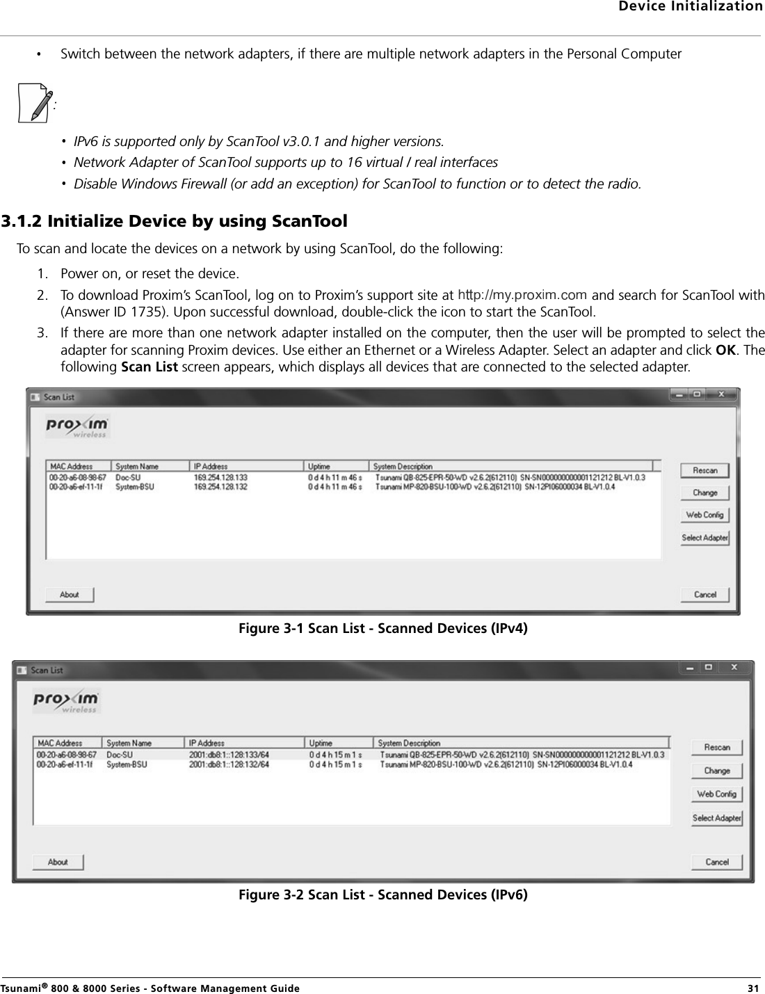
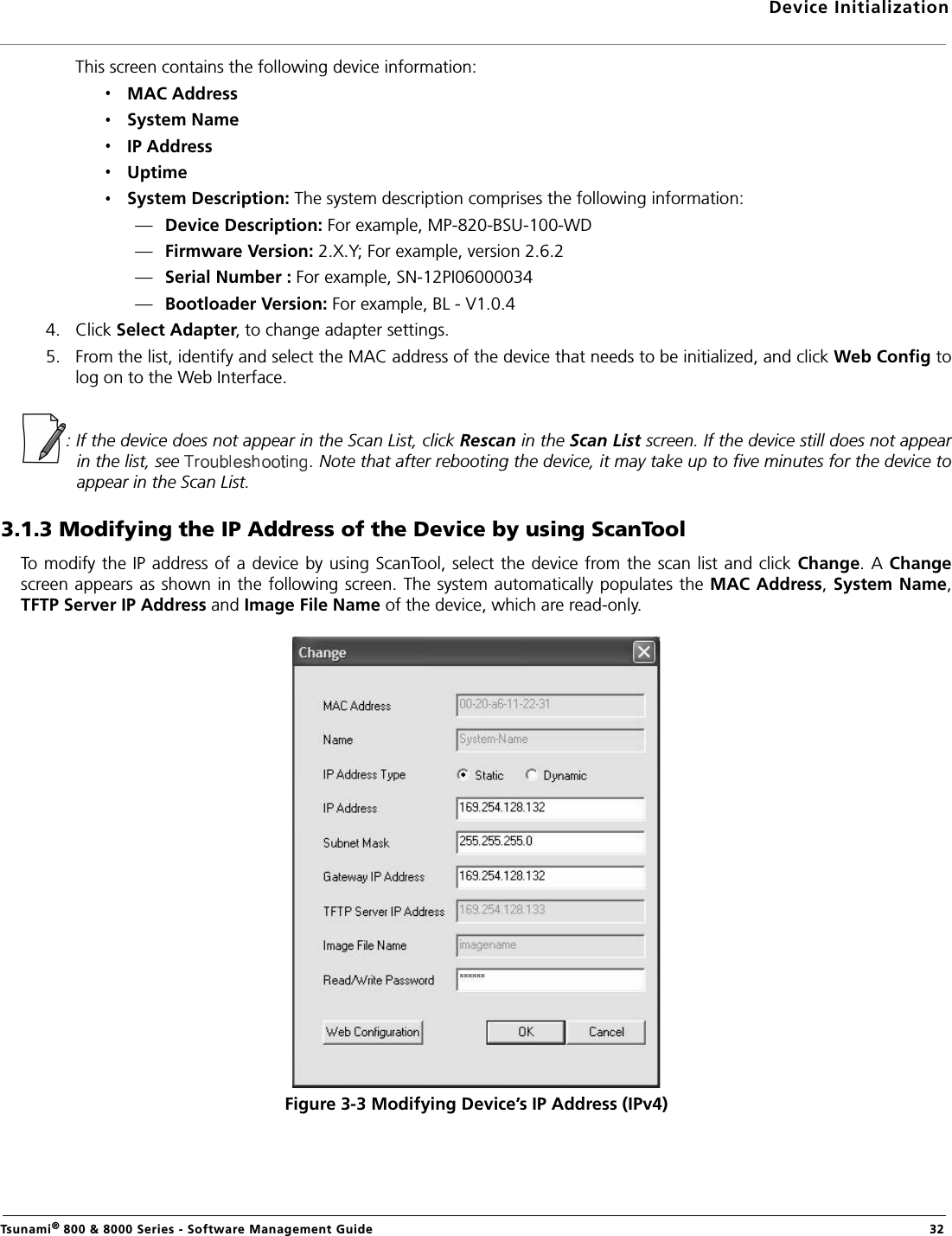
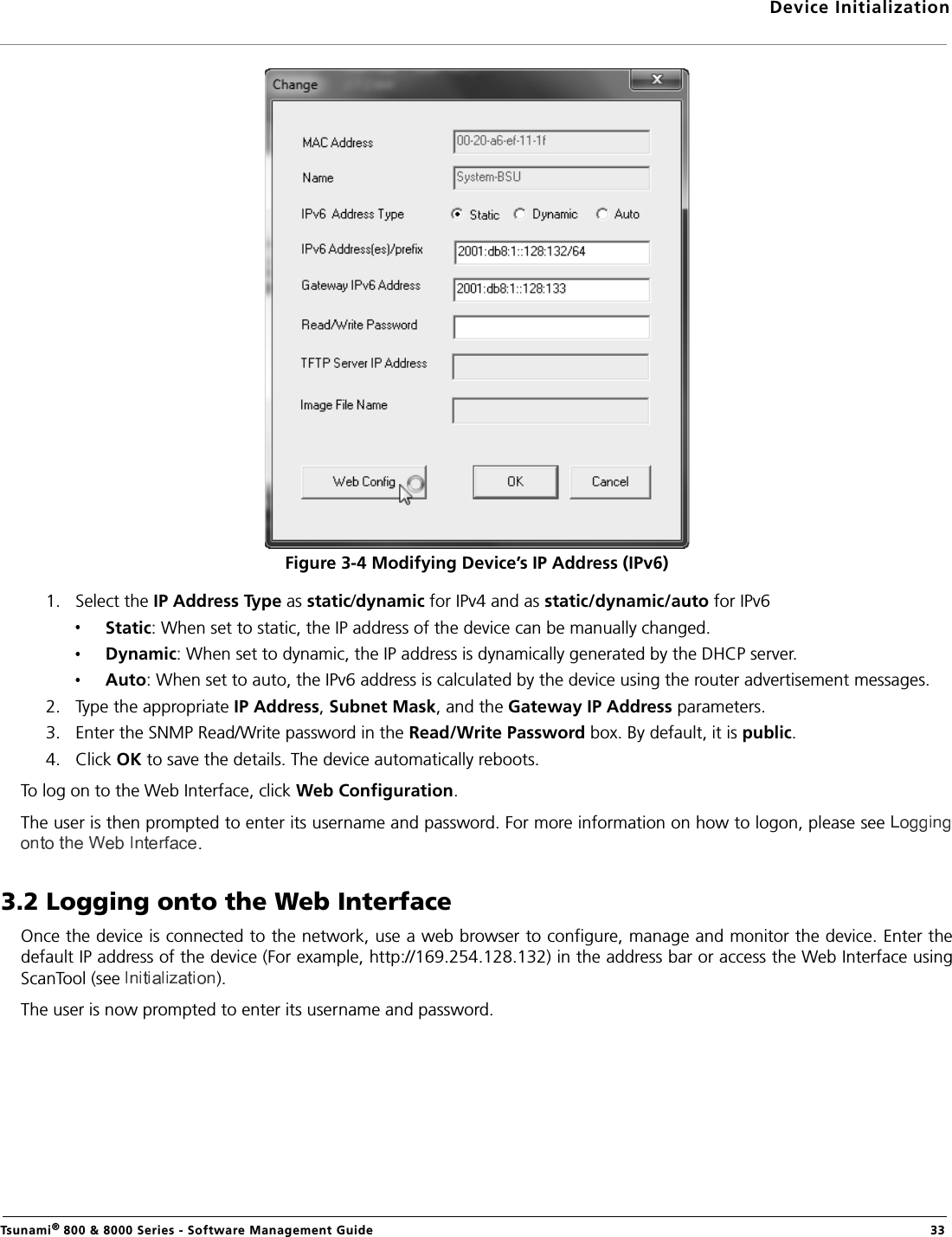
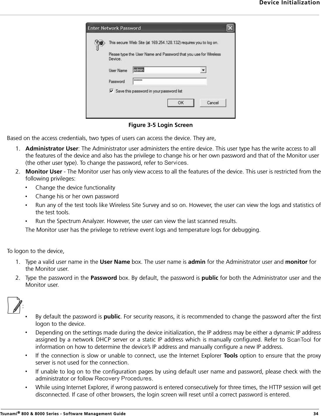
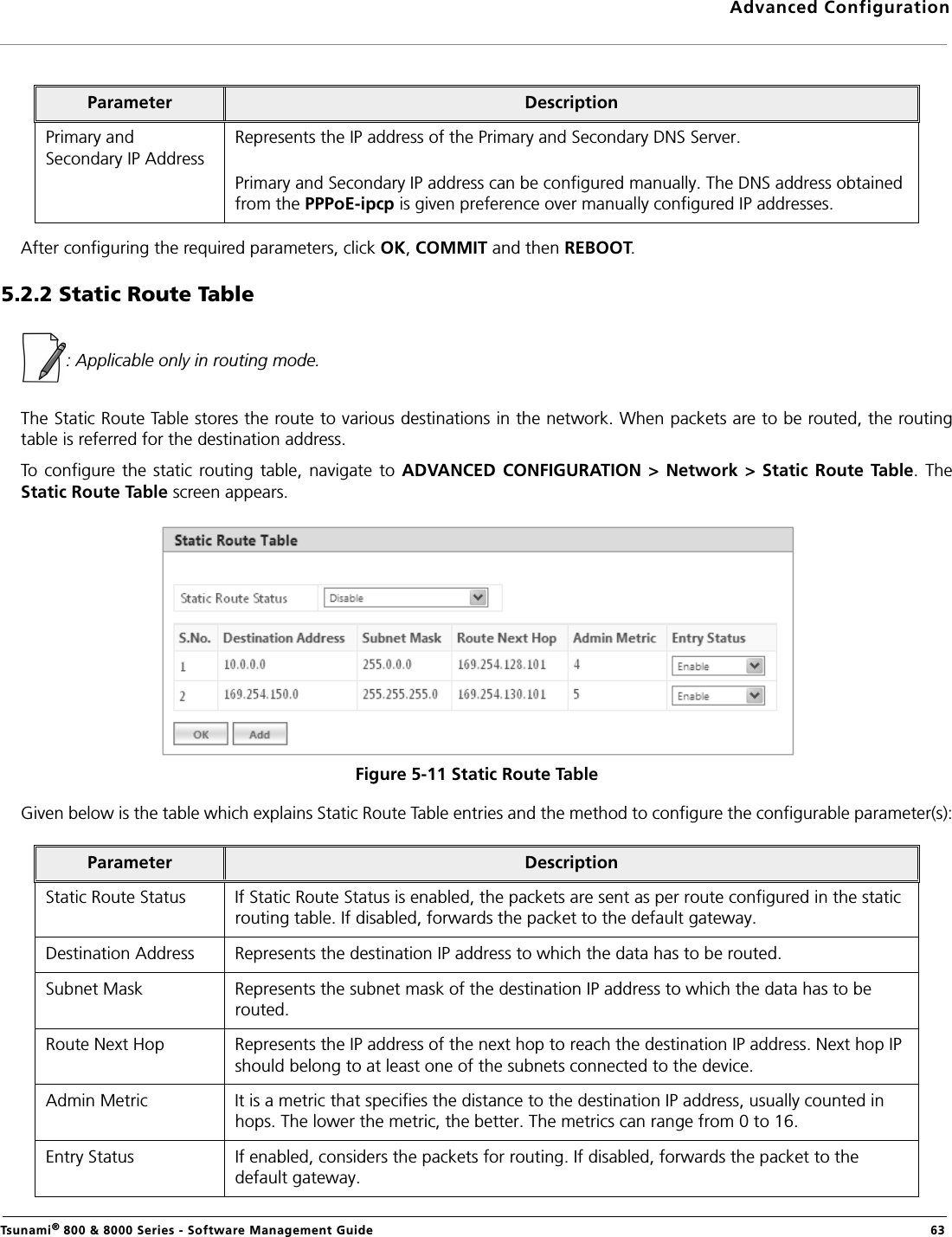
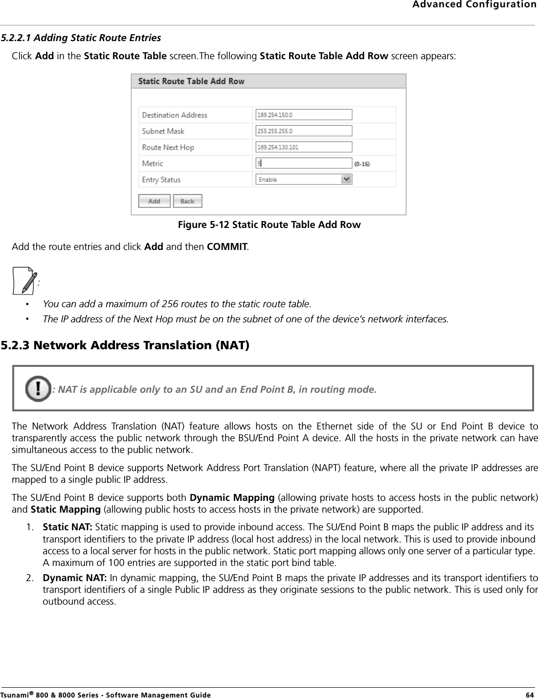

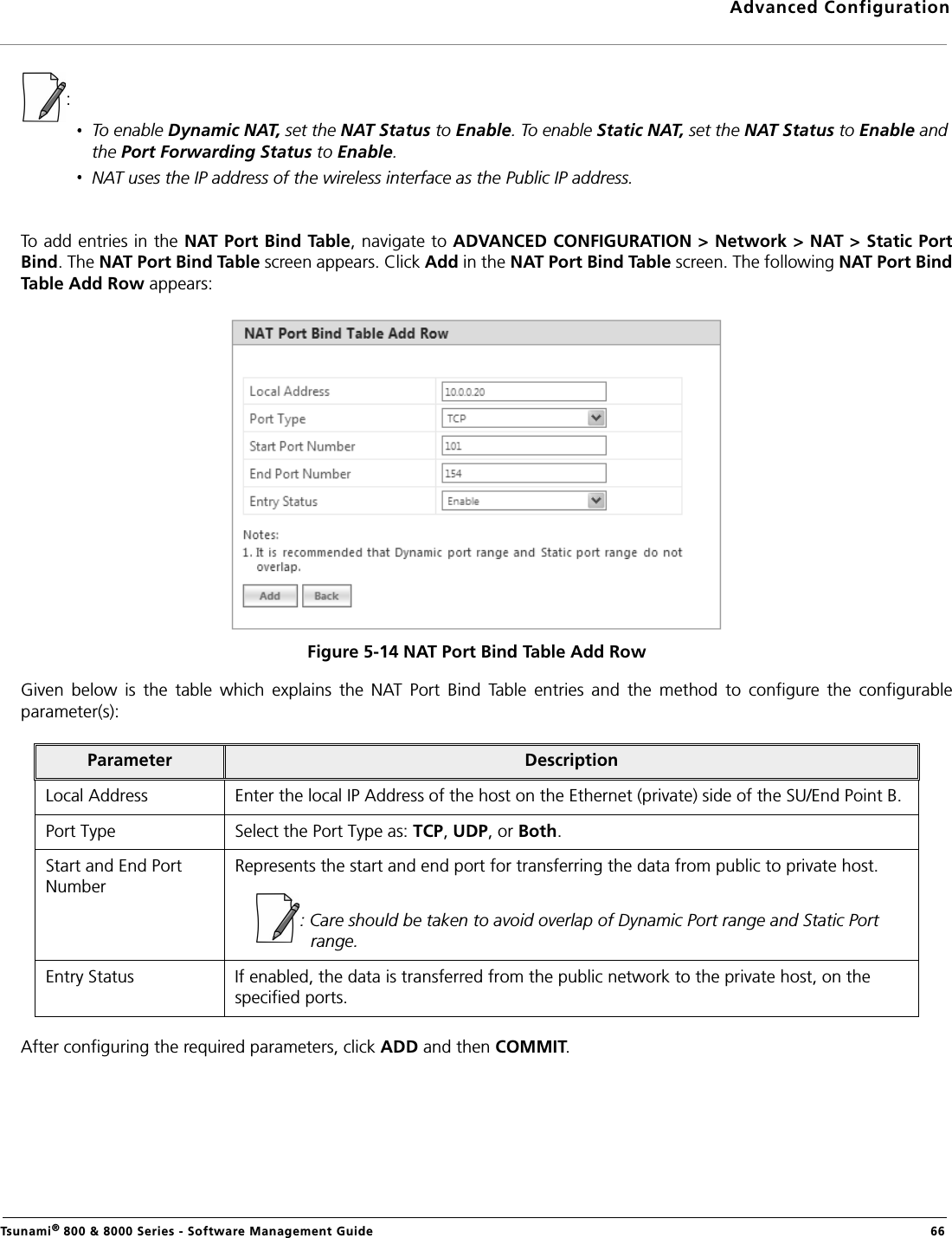
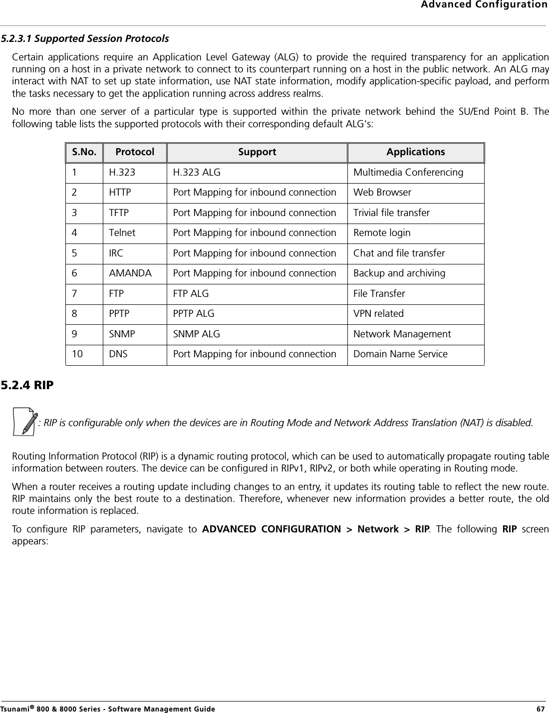
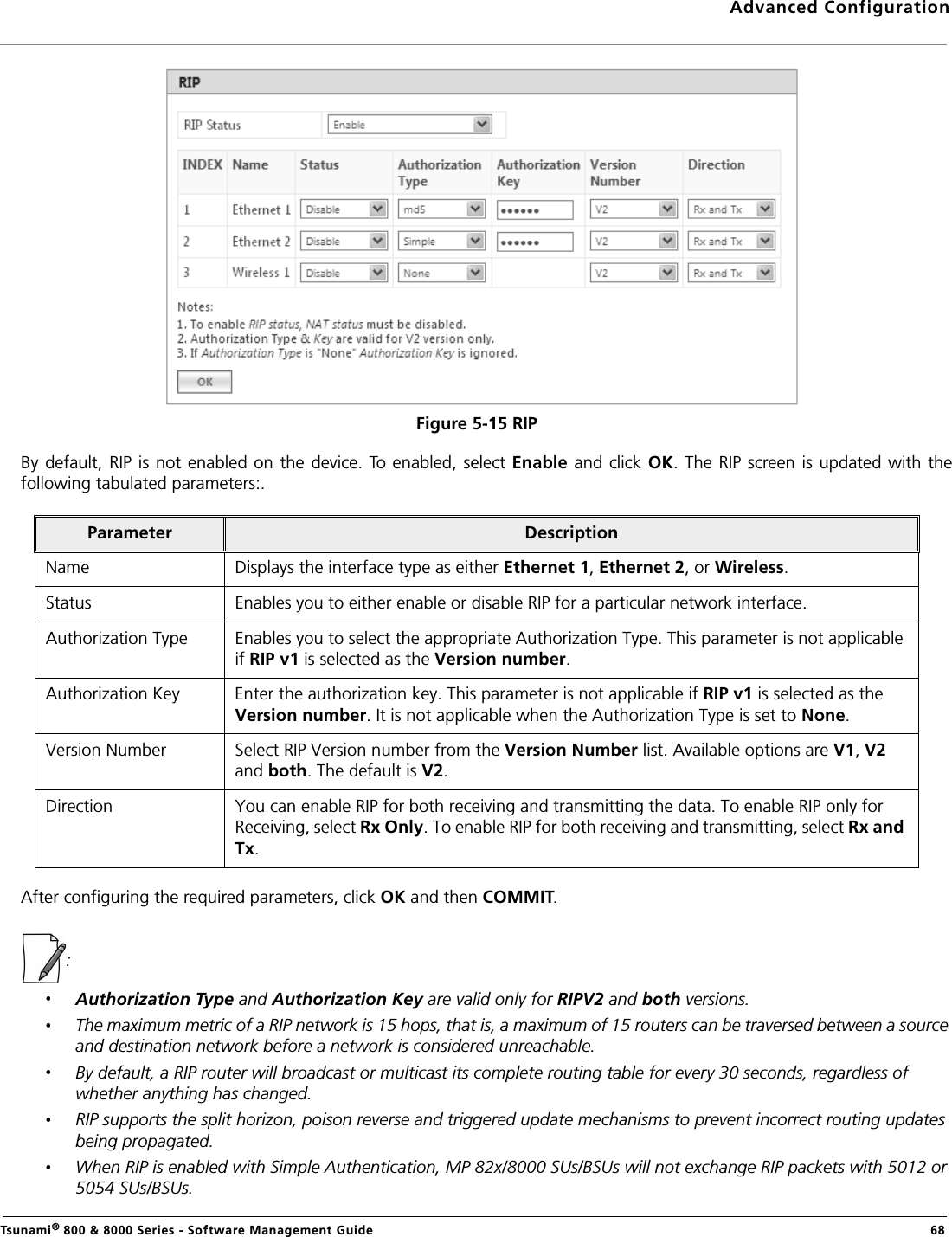
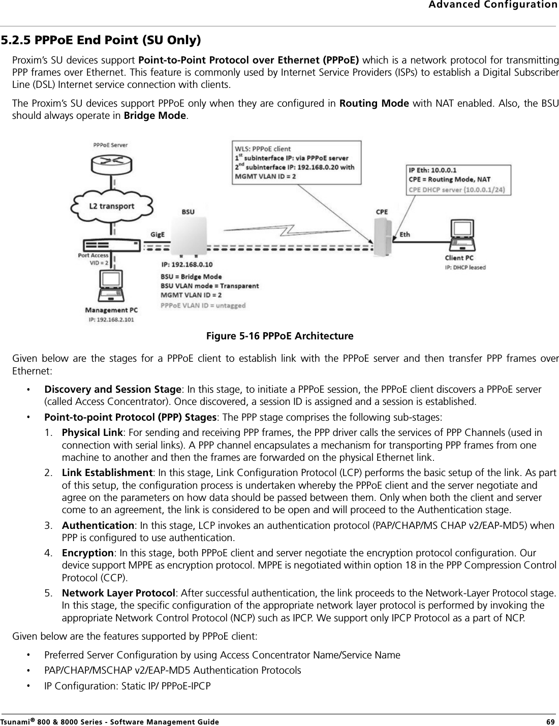
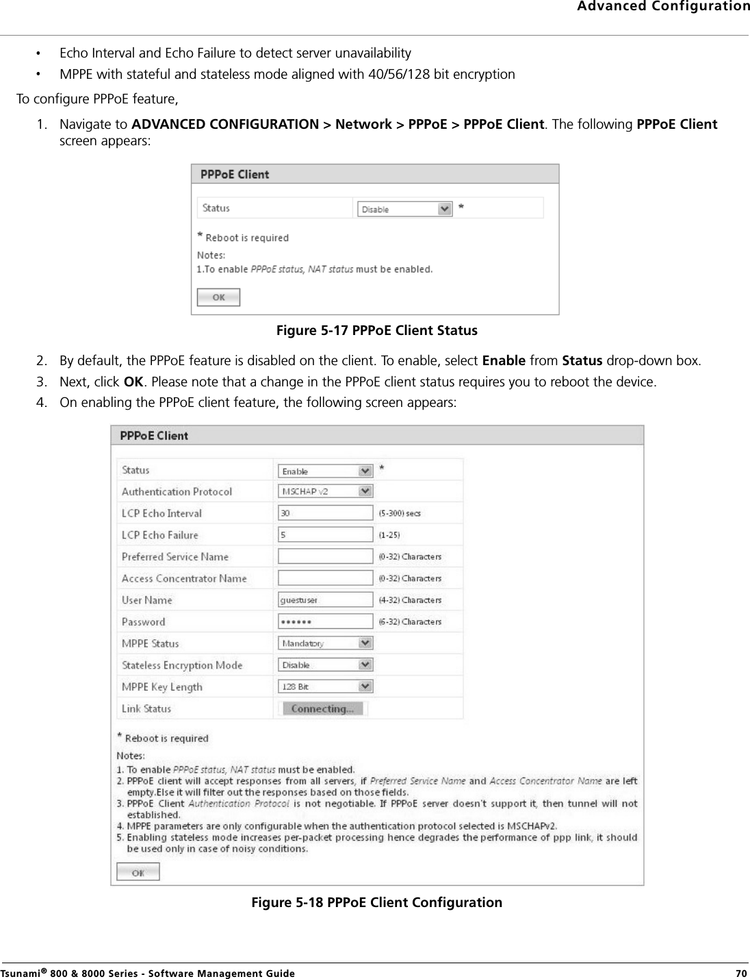
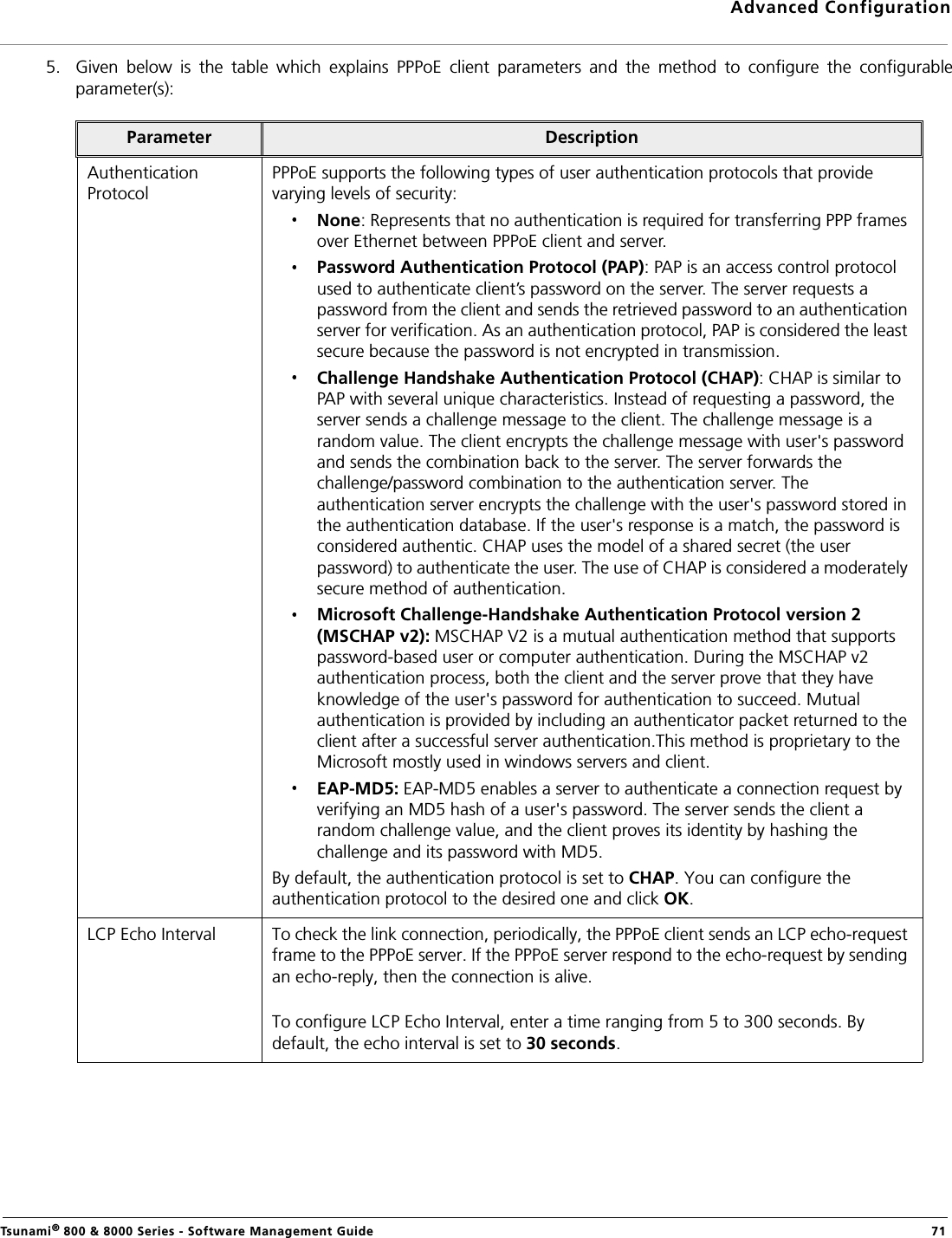
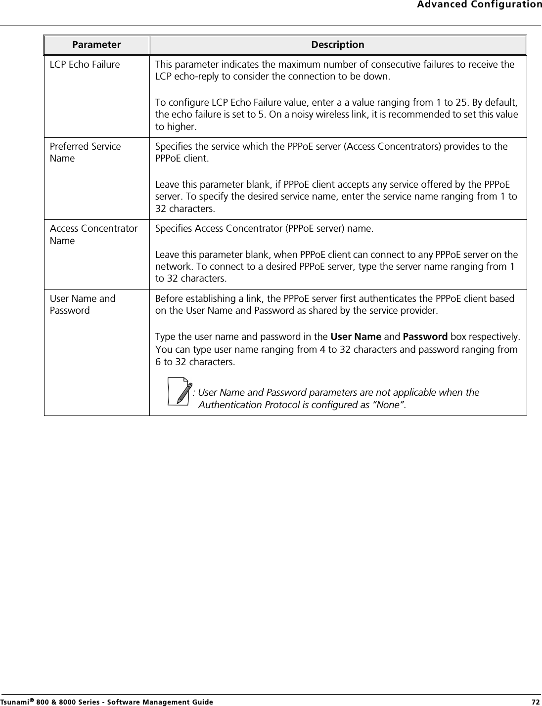
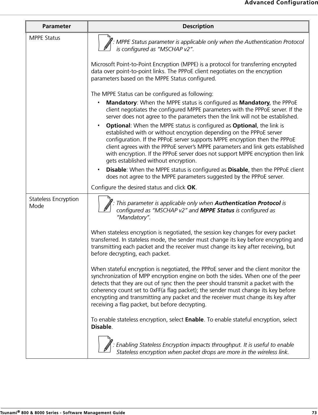
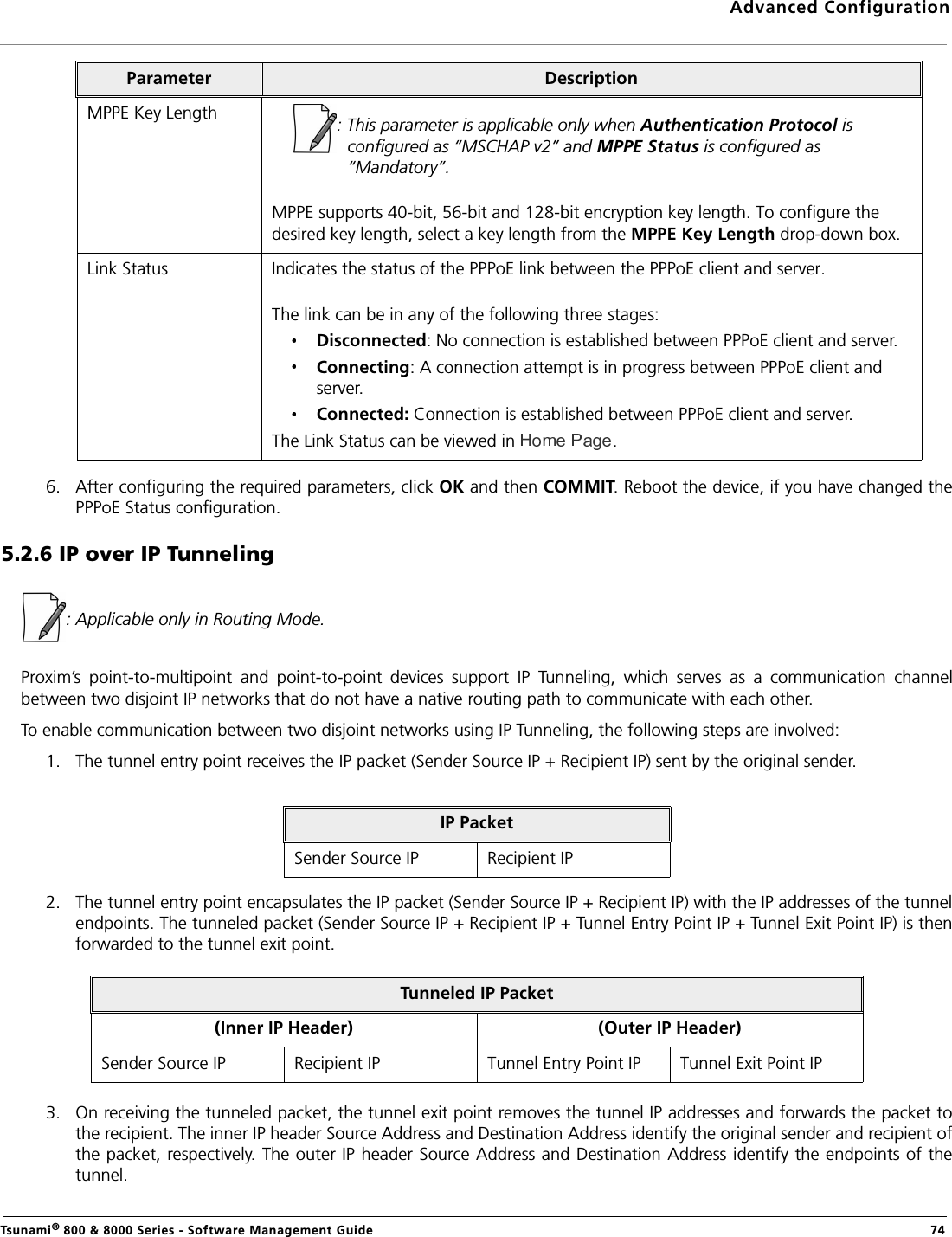
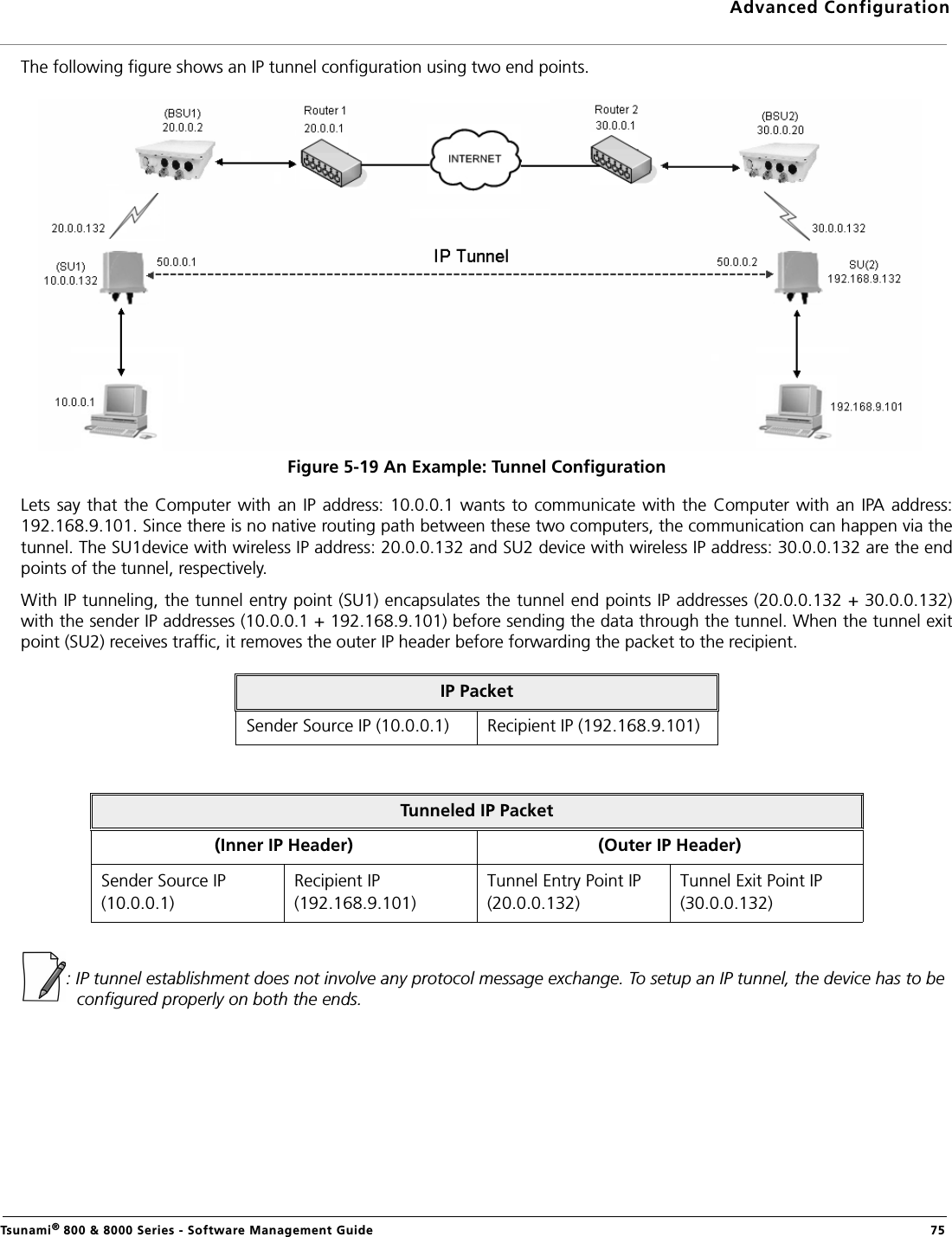
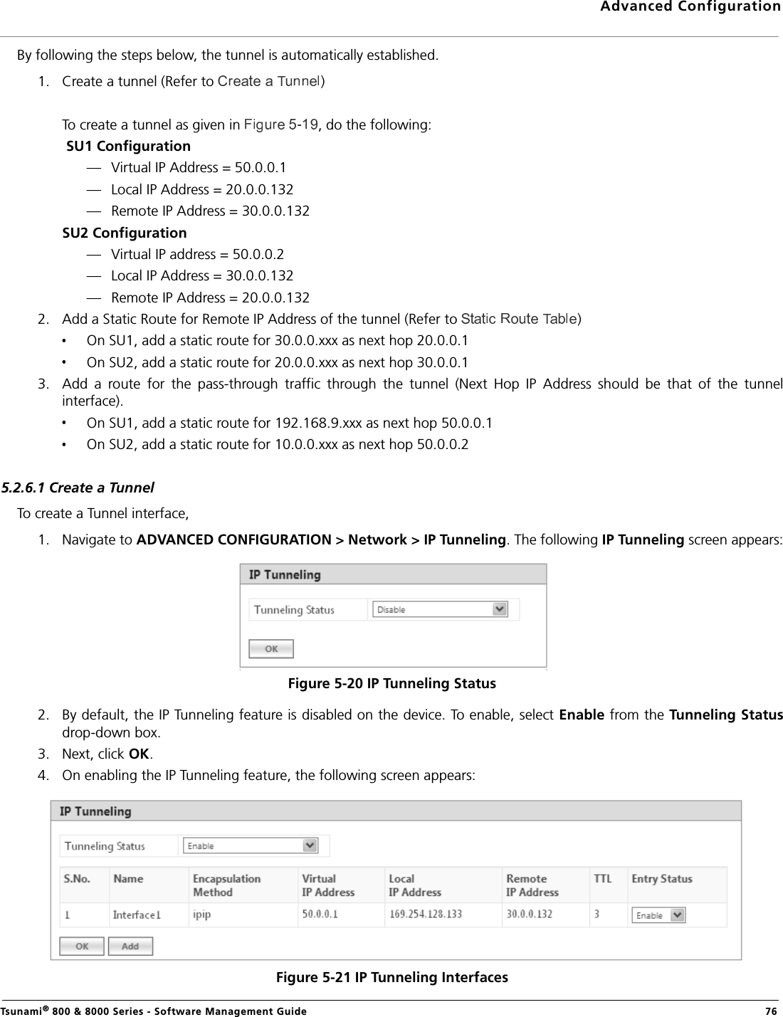
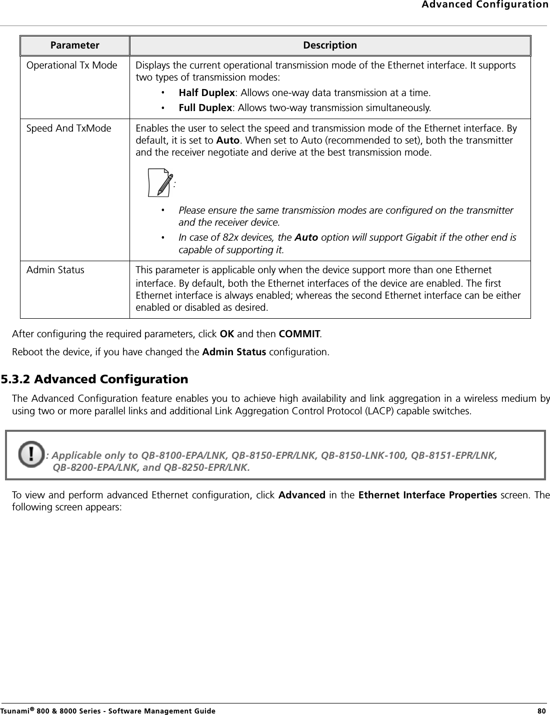

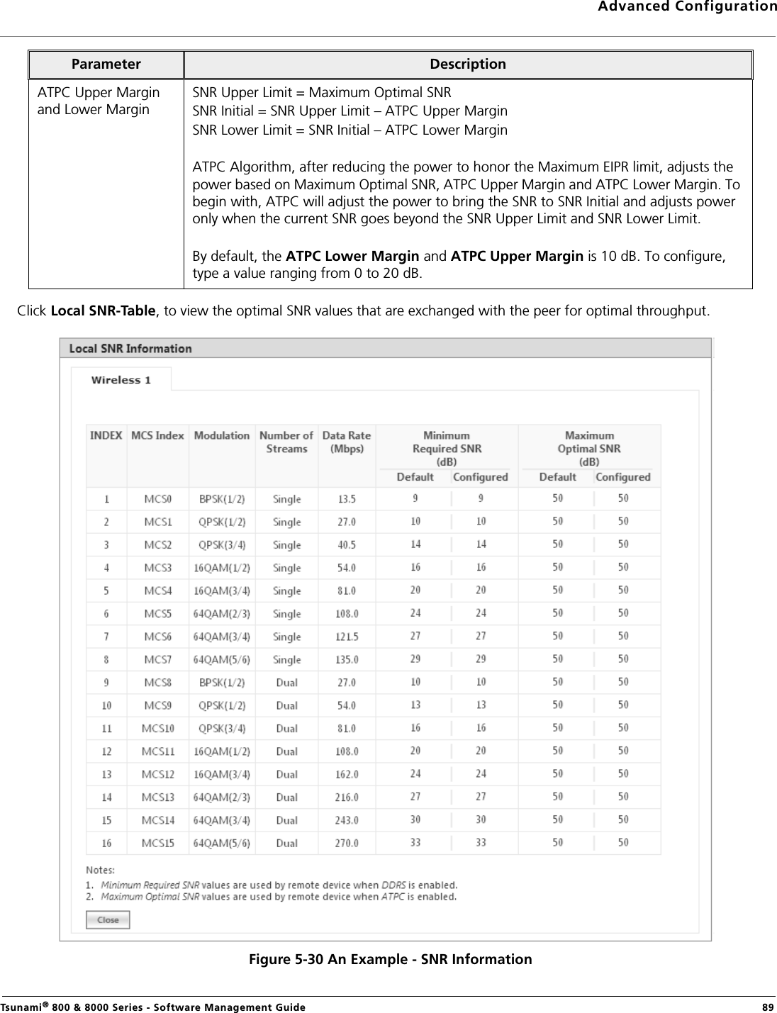
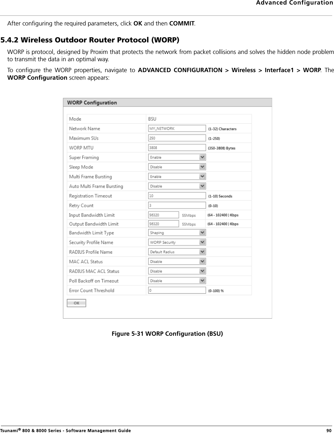
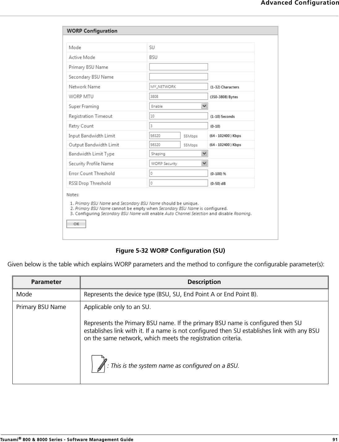
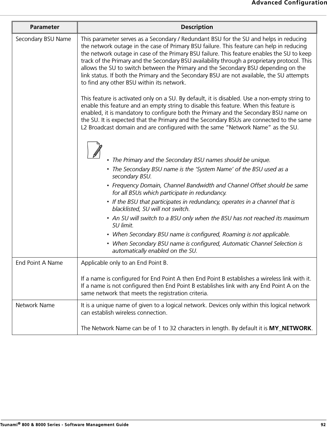
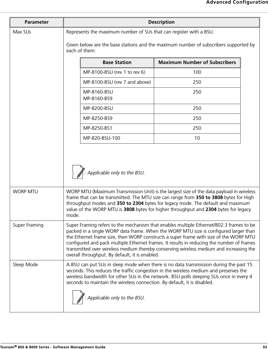
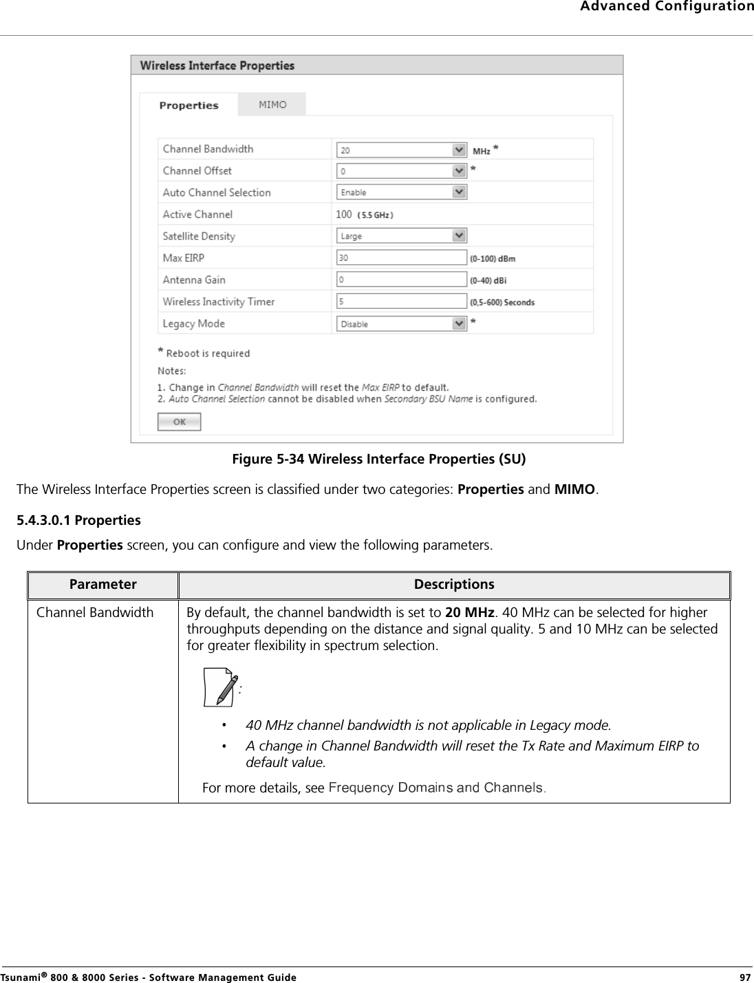
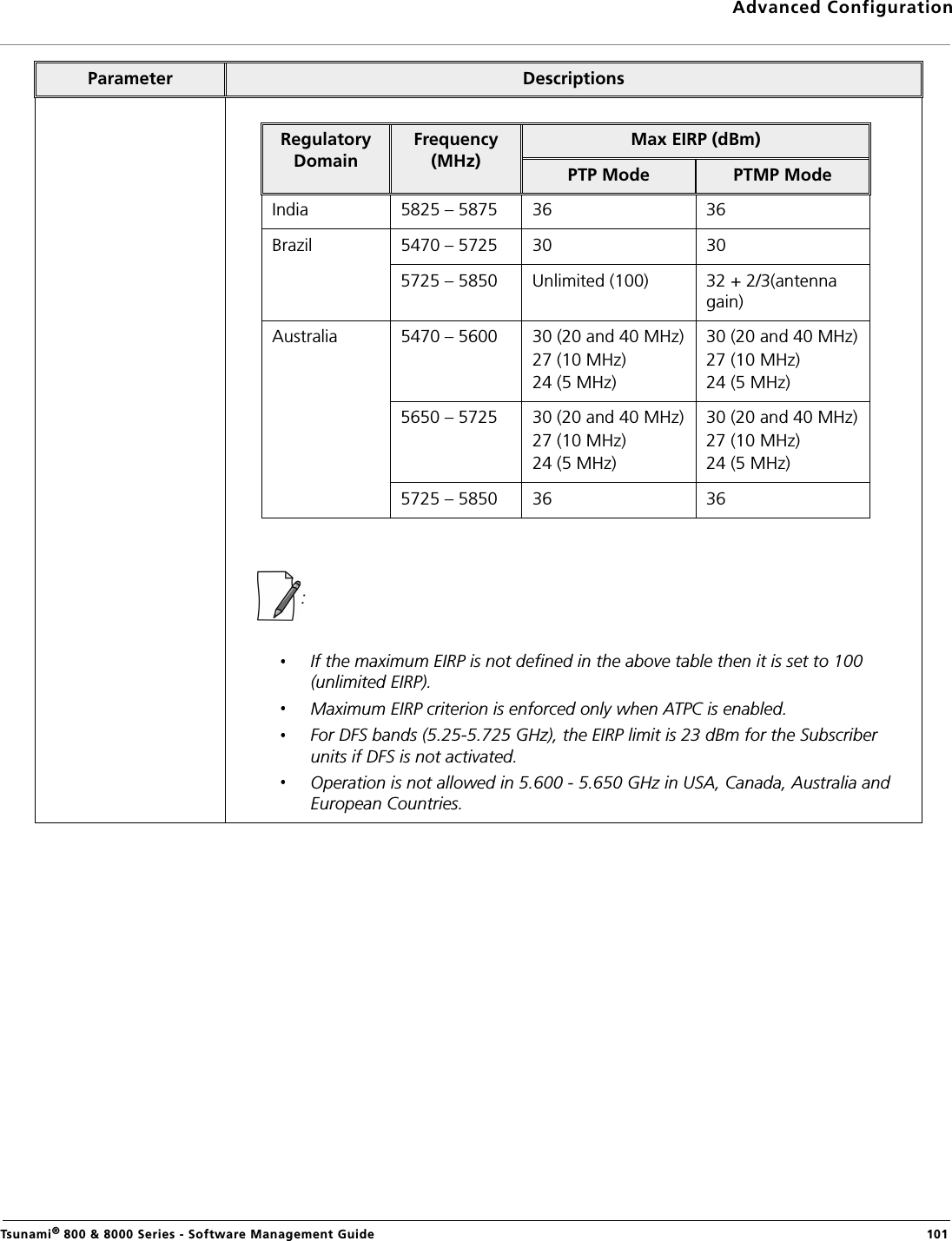
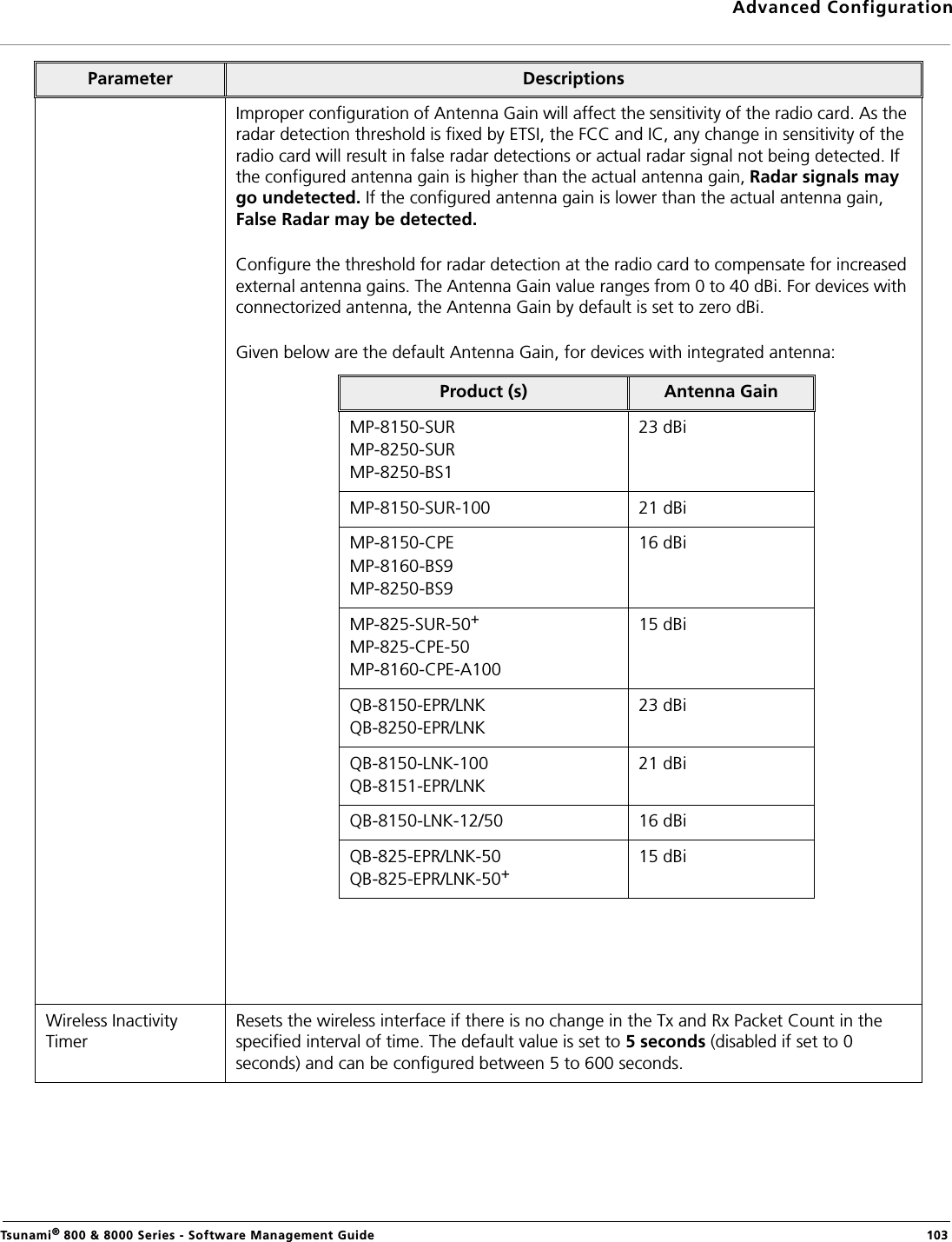
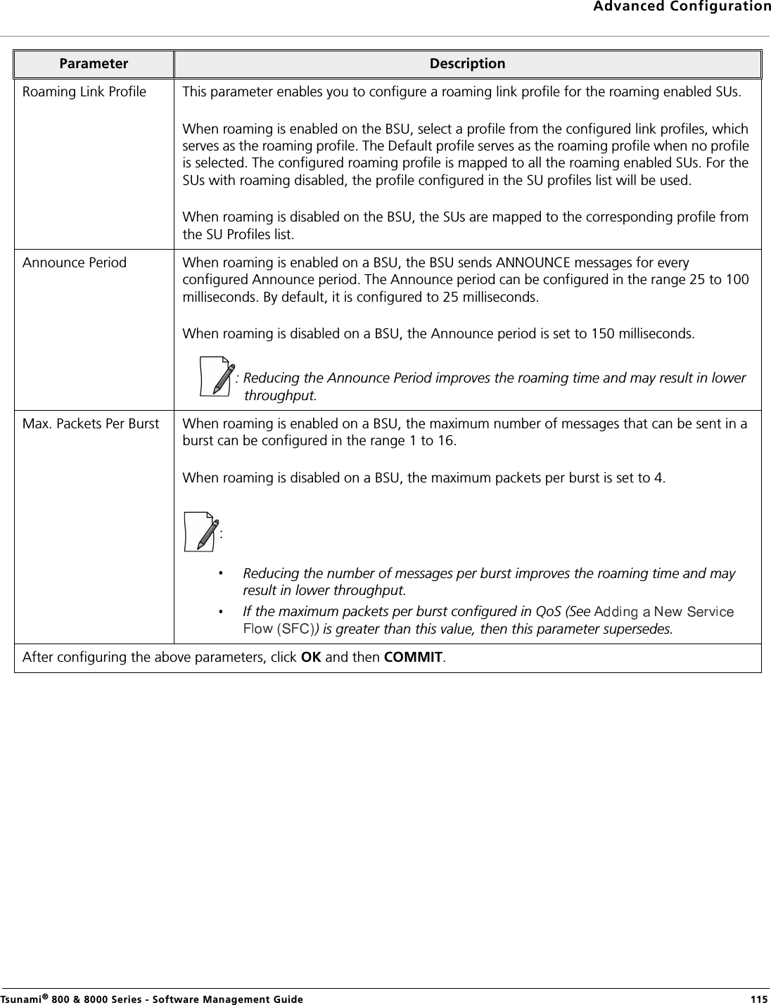
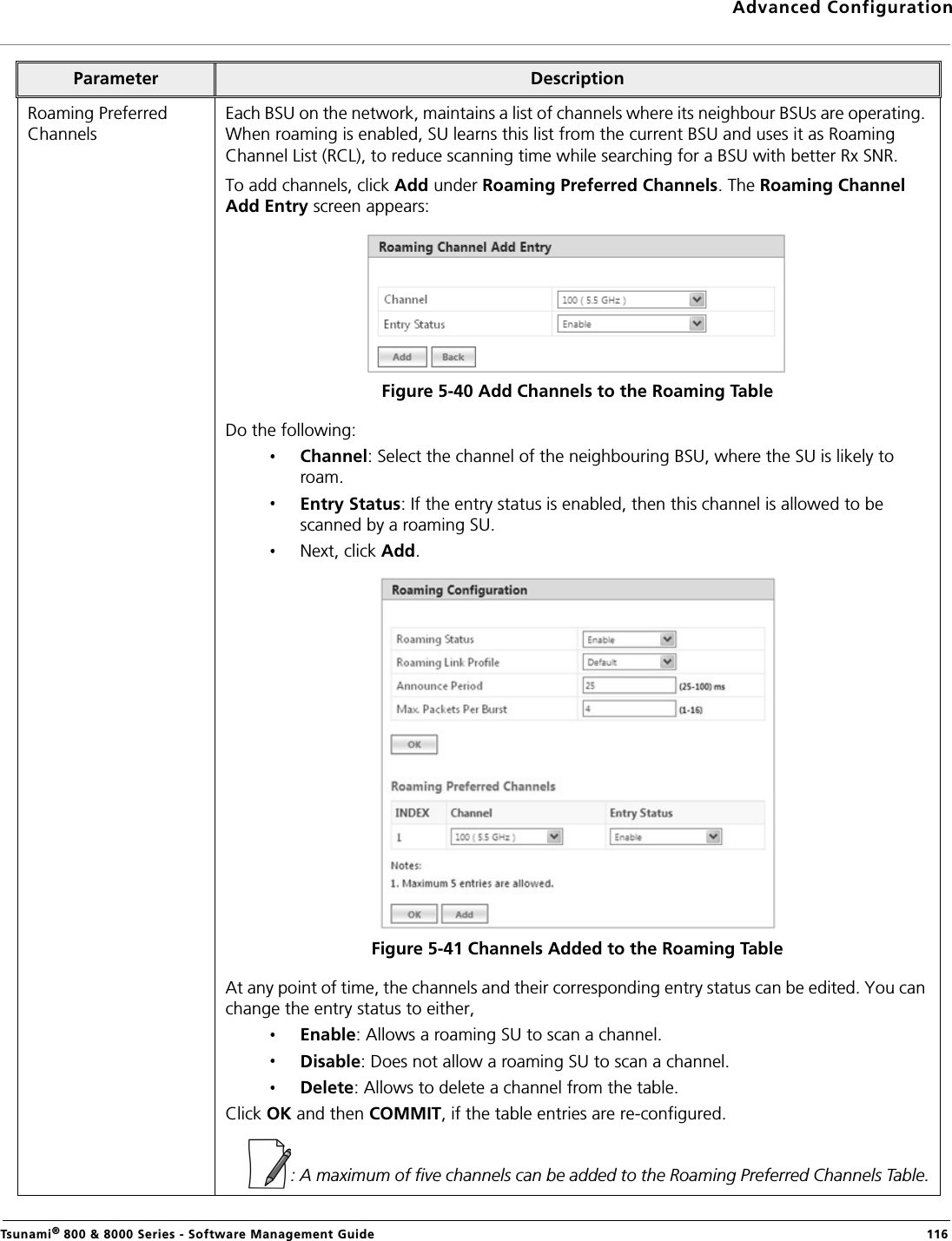
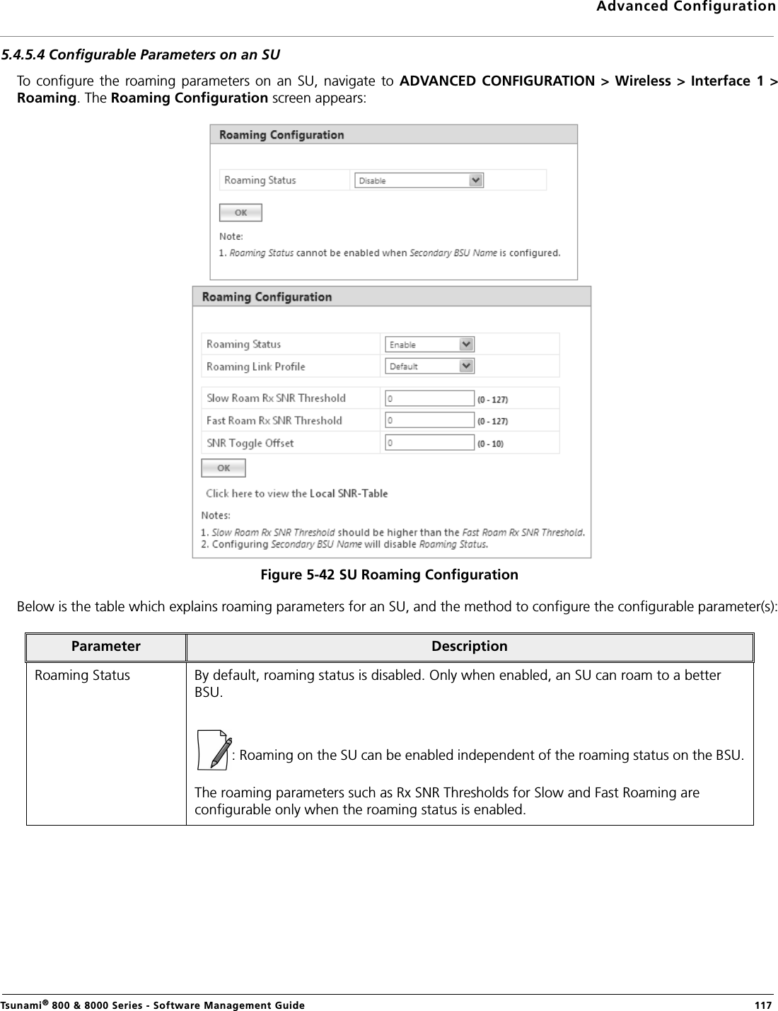
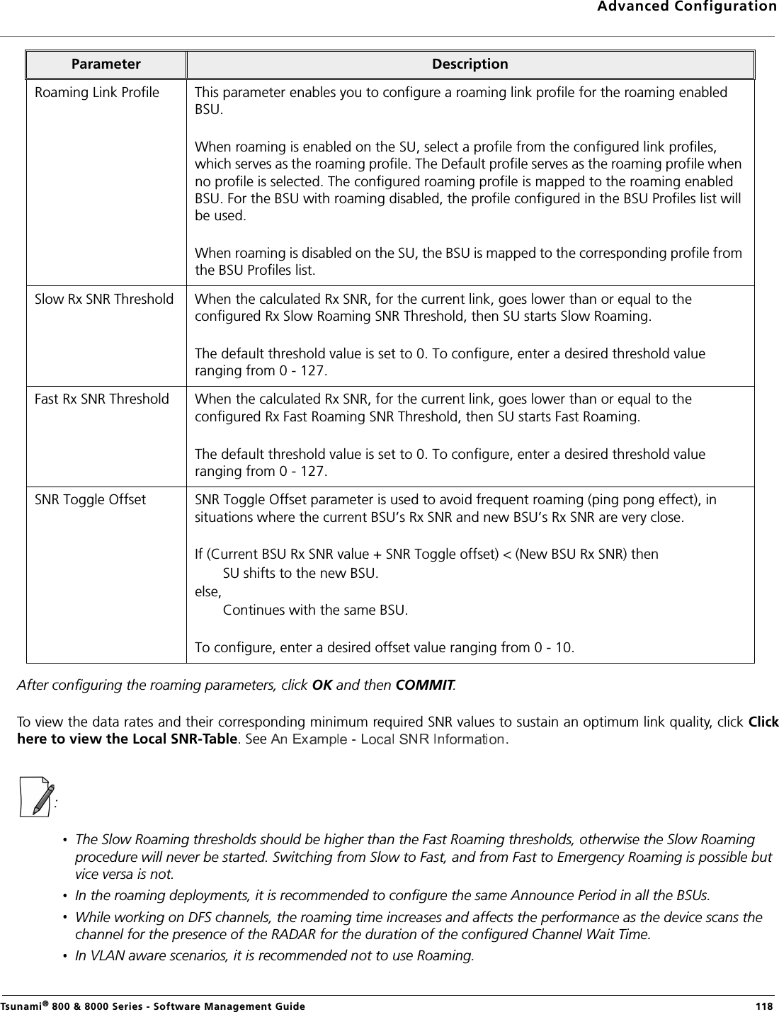
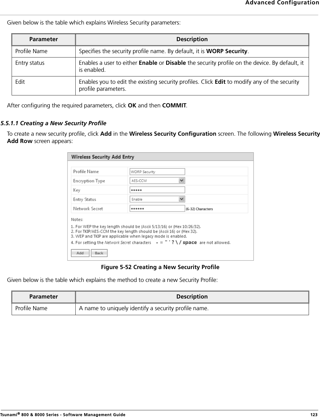
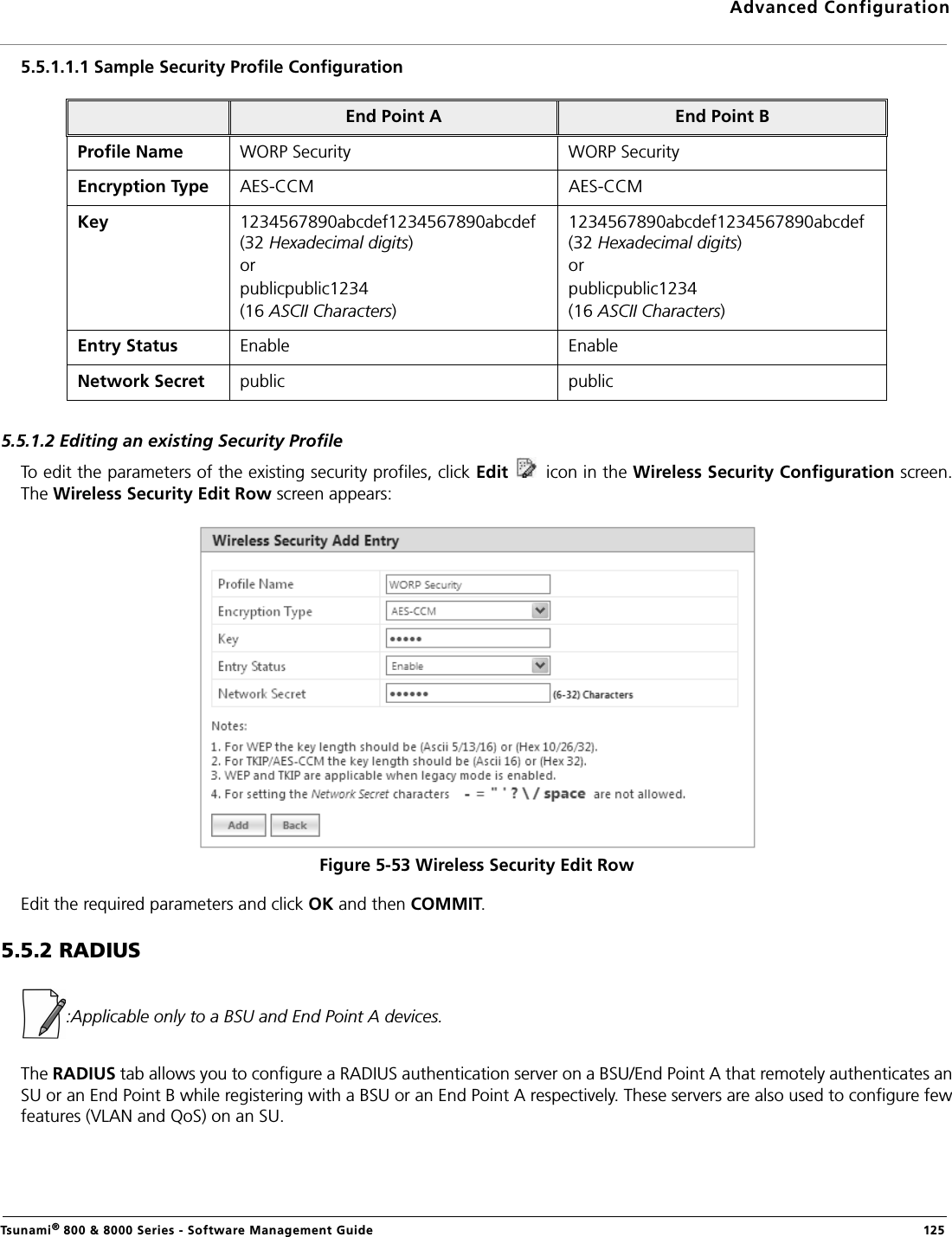
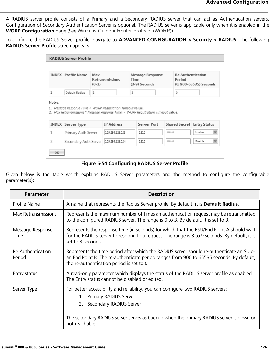
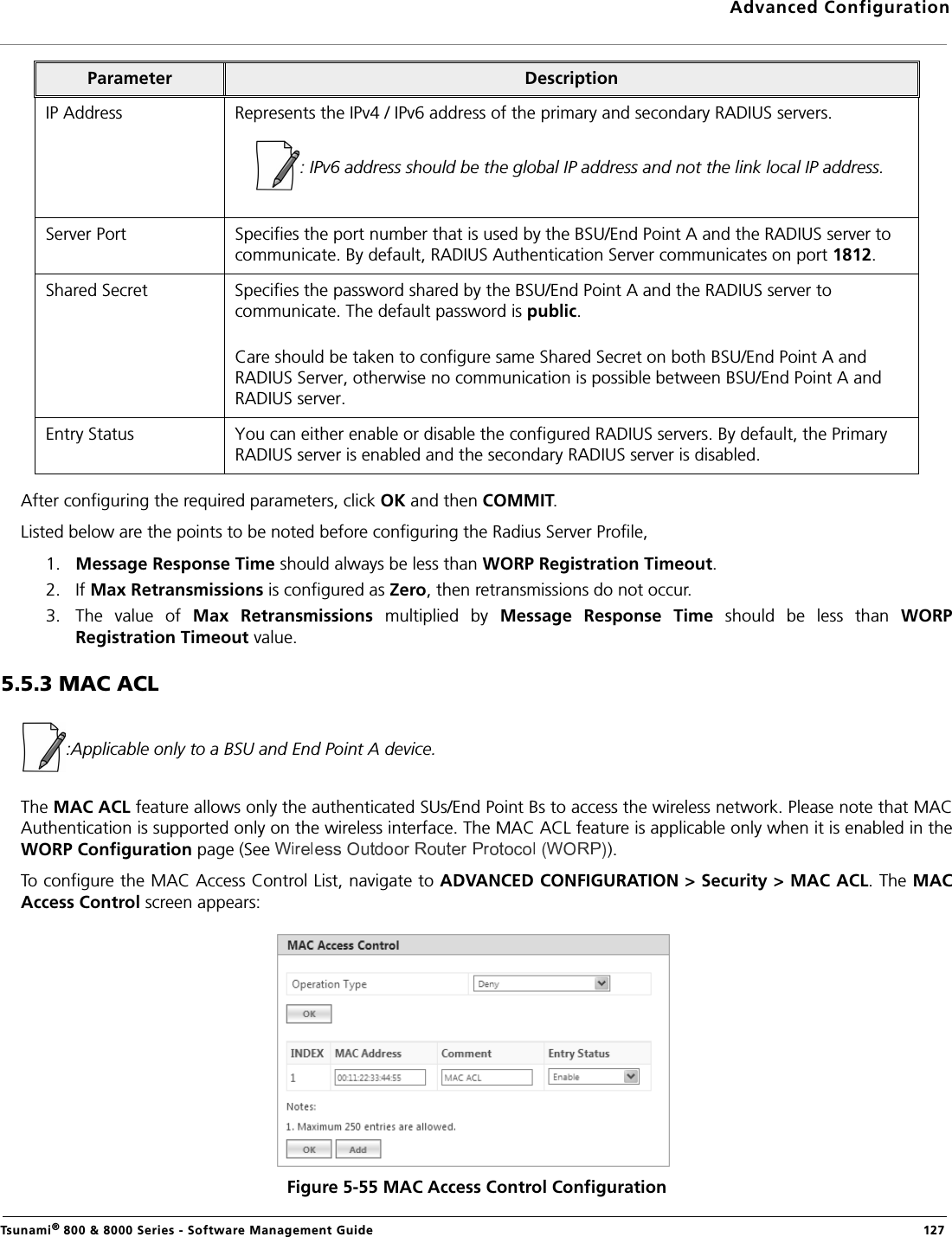
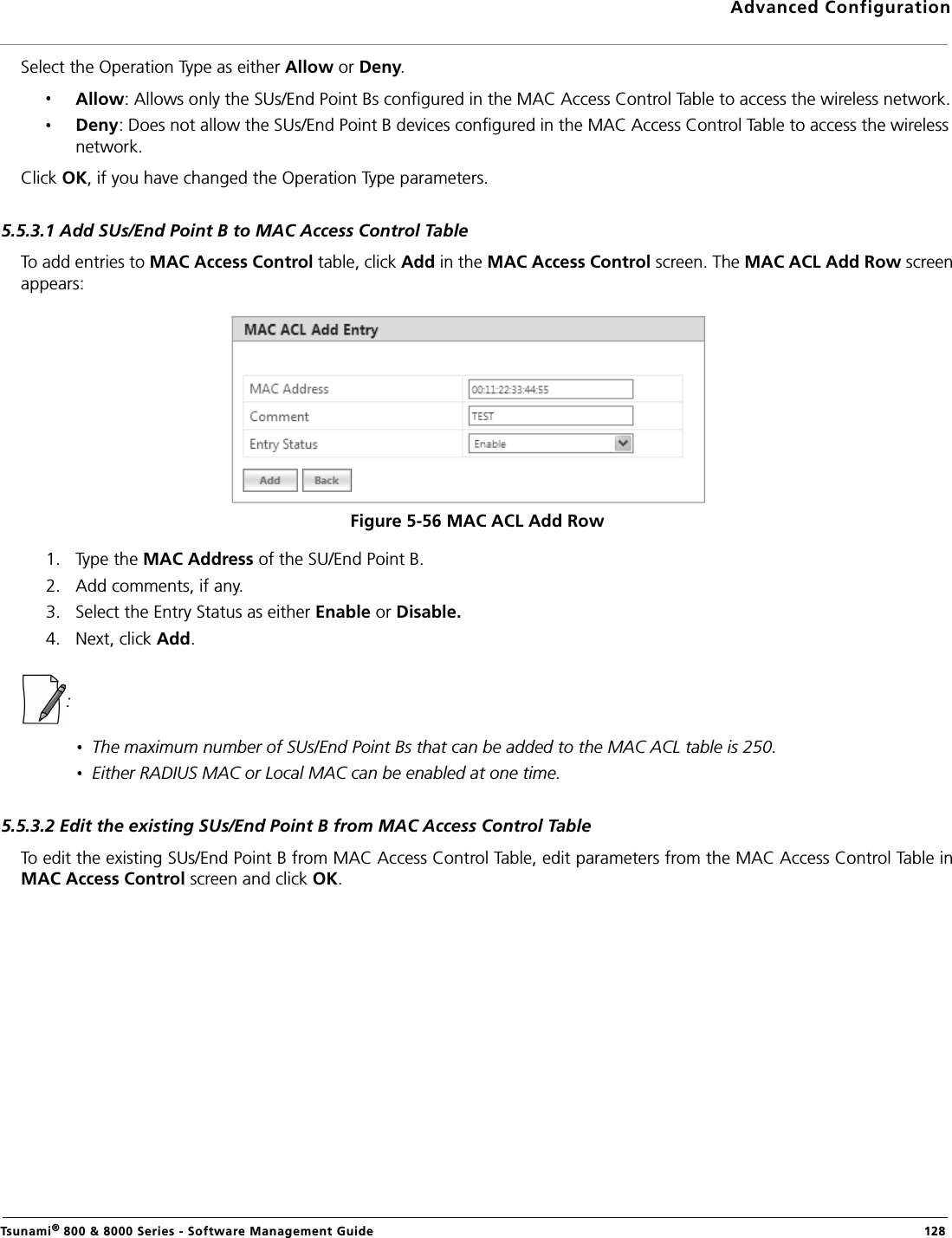
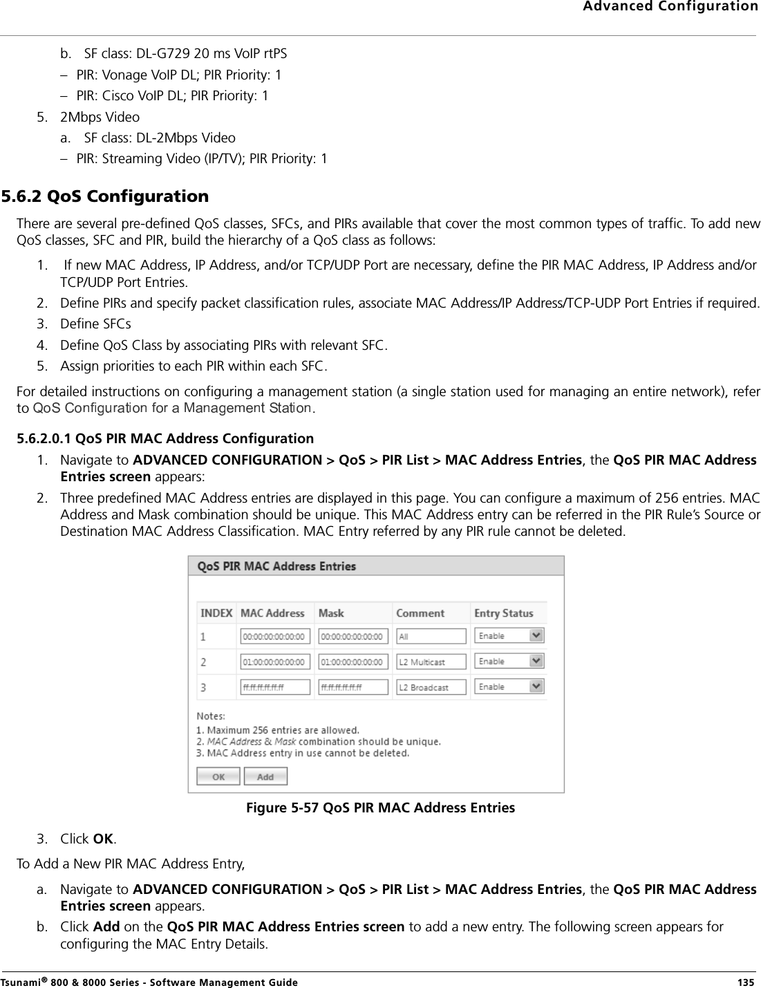
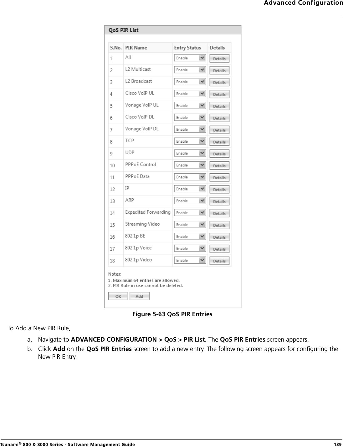
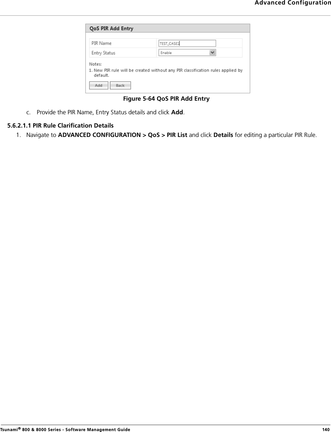
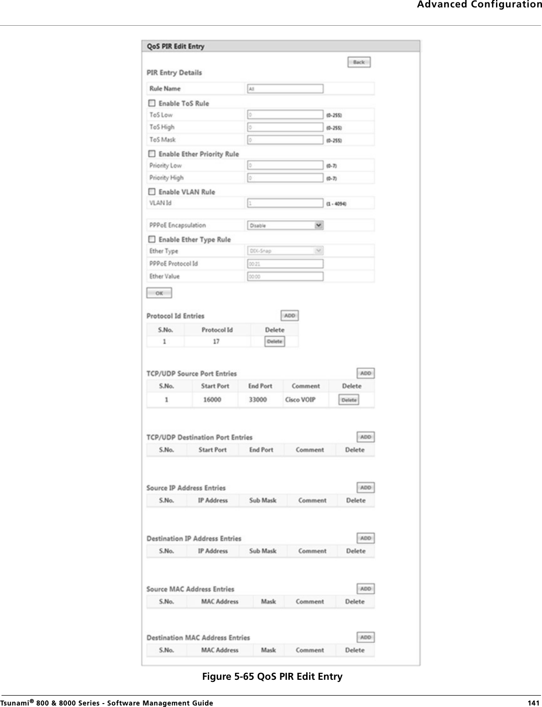
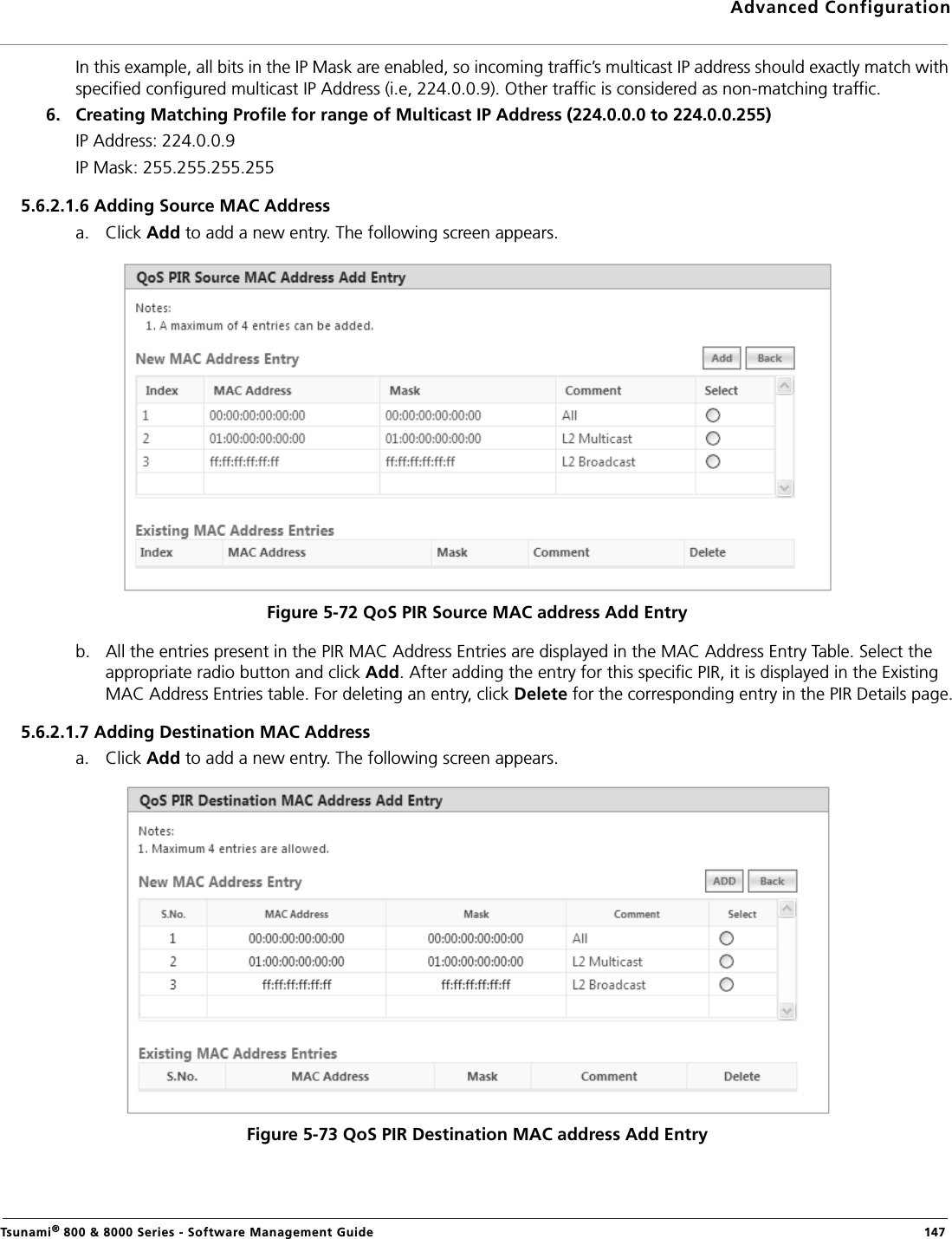
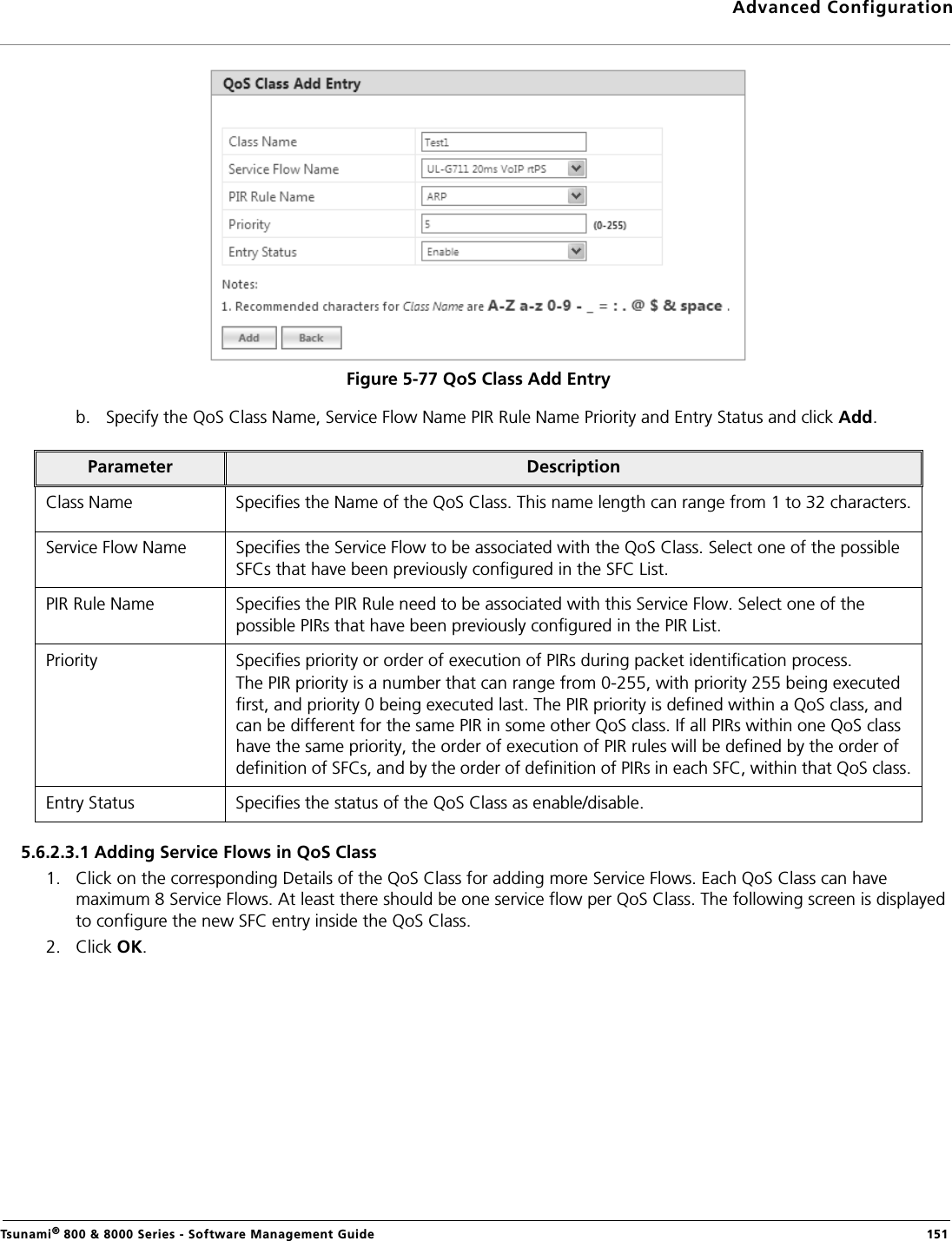
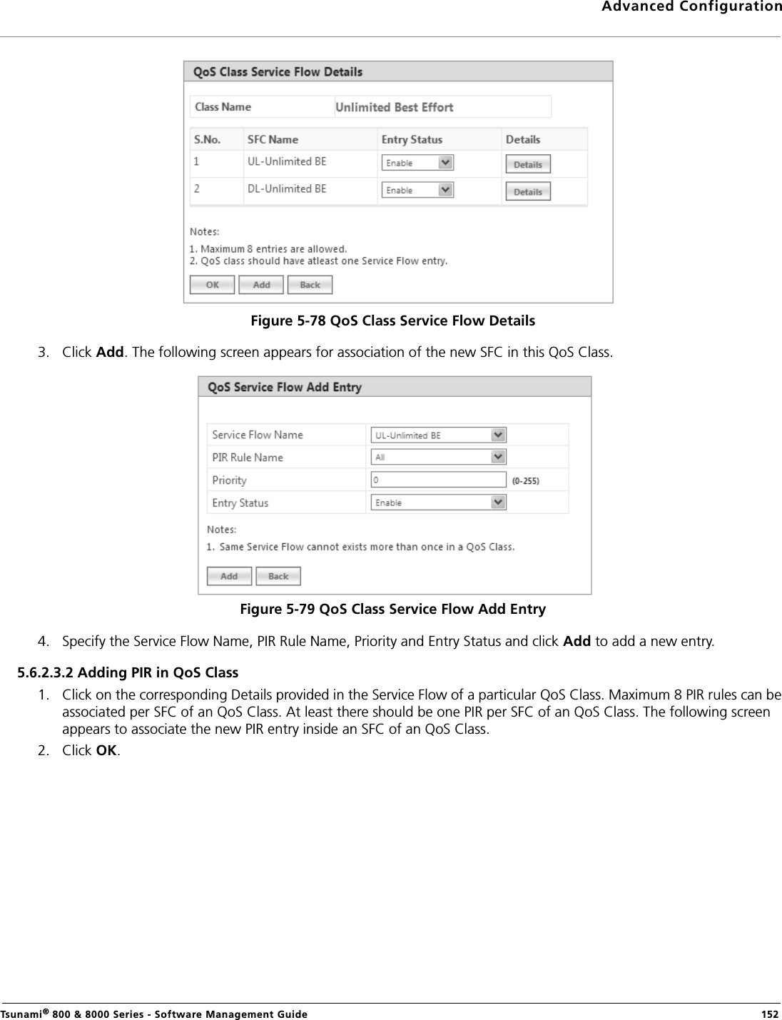
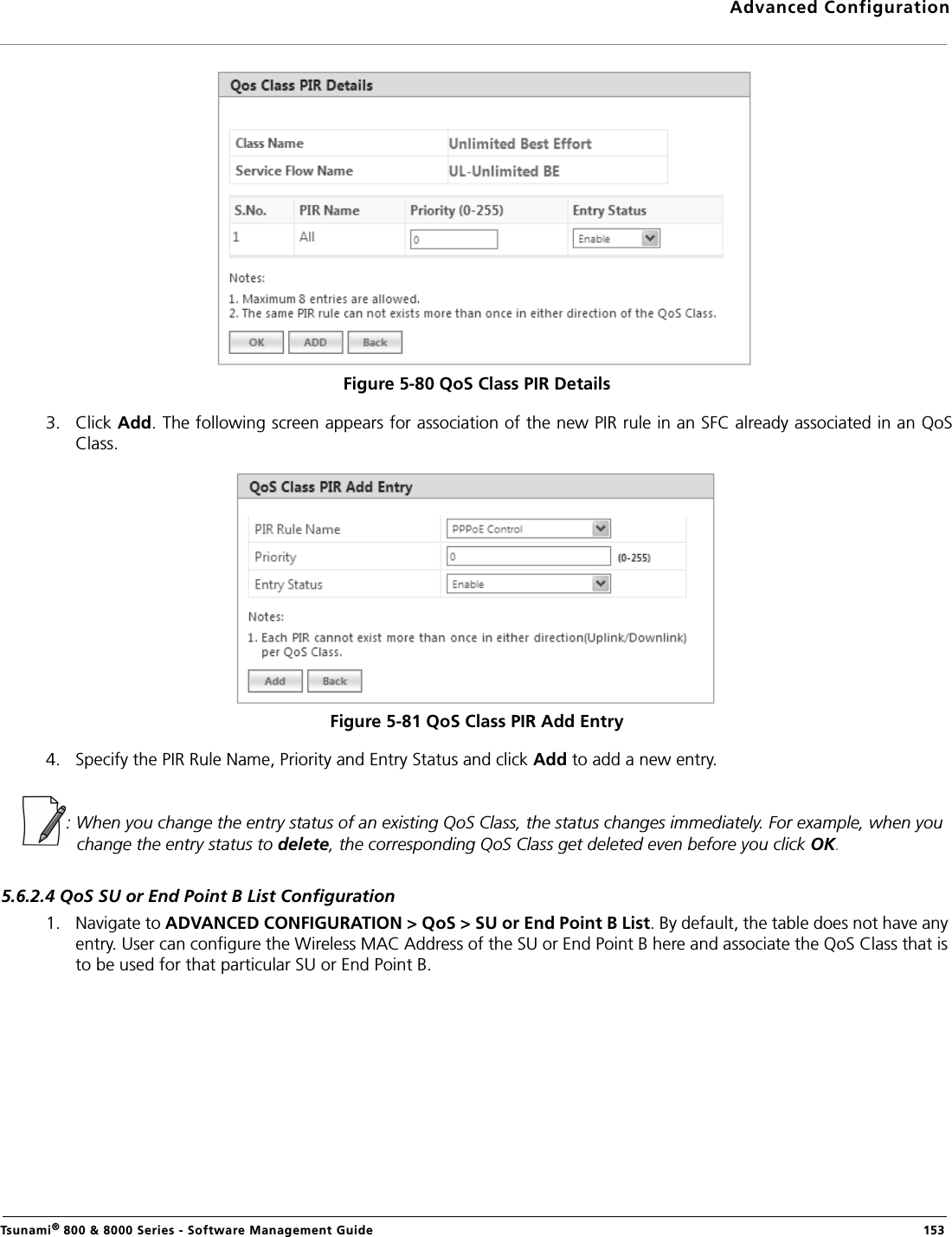
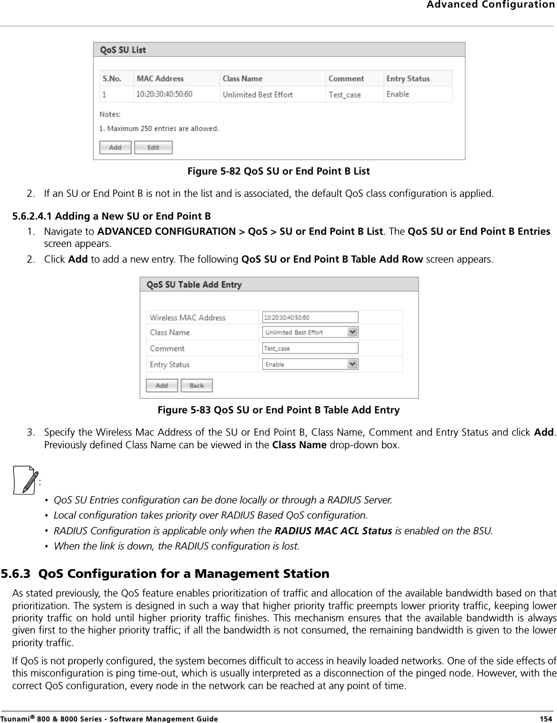
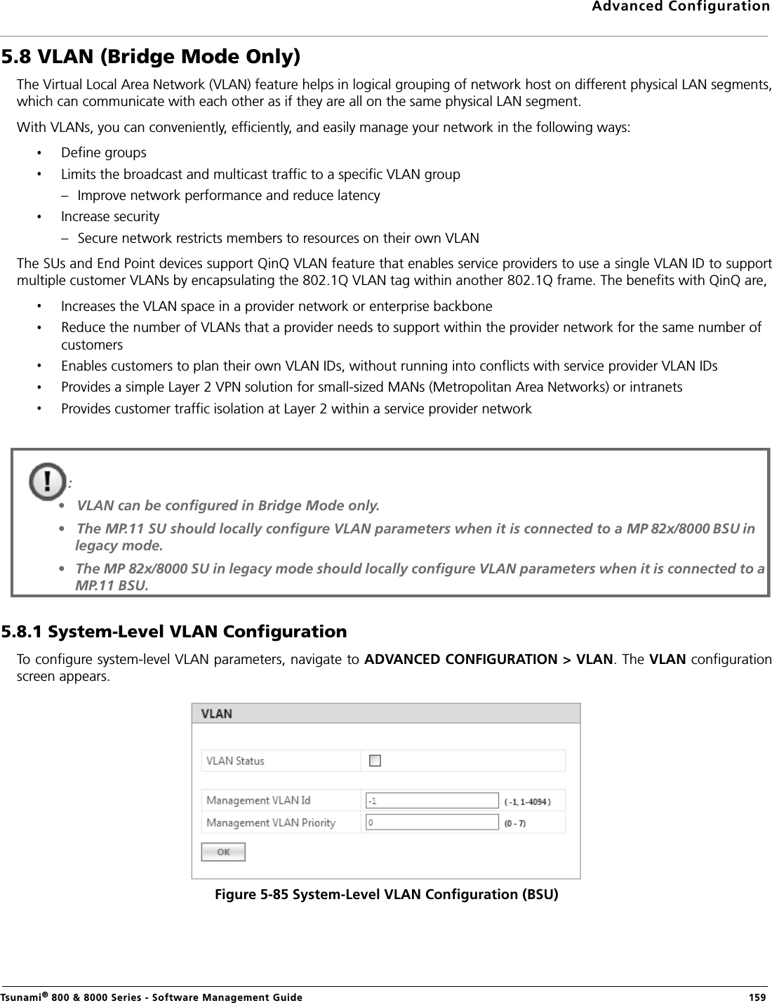
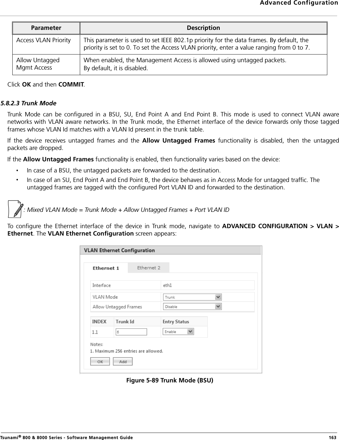
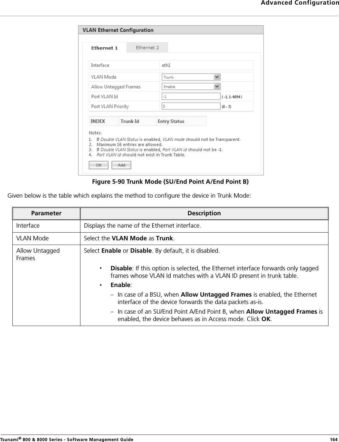
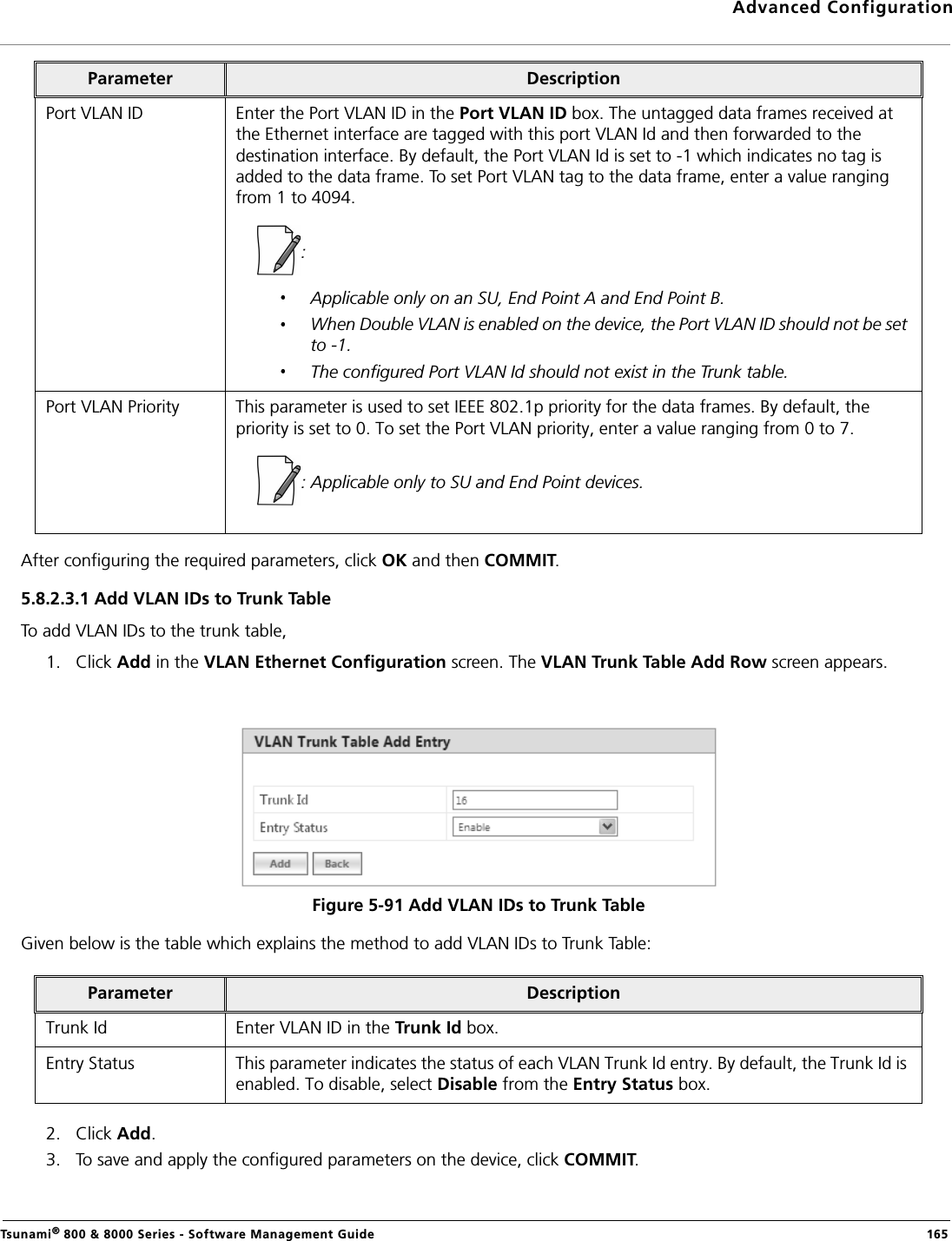
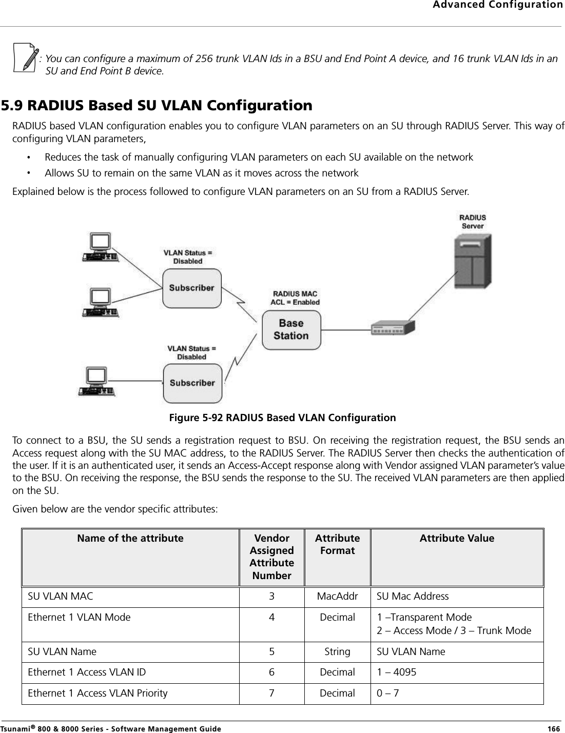
![Advanced ConfigurationTsunami® 800 & 8000 Series - Software Management Guide 102Antenna Gain When using external antenna, the professional installer should ensure to configure proper antenna gain so that the radio does not exceed the EIRP allowed per regulatory domain.Calculate the antenna gain as follows: Antenna Gain to be configured = Antenna Gain of the antenna used - Cable LossExample: Consider an example where the device is operating in United States 5.3 GHz with the EIRP 30 dBm. The antenna gain of the antenna used is 23 dBi and the cable loss is 1dB. Given this case, Configurable Antenna Gain = [23 dBi – 1 dB] = 22 dBiMaximum Radio Power = EIRP – Configured Antenna Gain = 30 dBm – 22 dBi = 8 dBmWith this configuration, the ATPC feature will limit the radio power to a maximum of 8 dBm to avoid exceeding EIRP limit of 30 dBm.Parameter Descriptions](https://usermanual.wiki/Proxim-Wireless/XB92WLE.Software-guide1/User-Guide-2355965-Page-102.png)