Proxim Wireless XB92WLE 802.11 a/n PCIe Module User Manual Tsunami800 8000 SW Guide v5 2 SW2 6 2
Proxim Wireless Corporation 802.11 a/n PCIe Module Tsunami800 8000 SW Guide v5 2 SW2 6 2
UserManual.wiki
>
Proxim Wireless
>
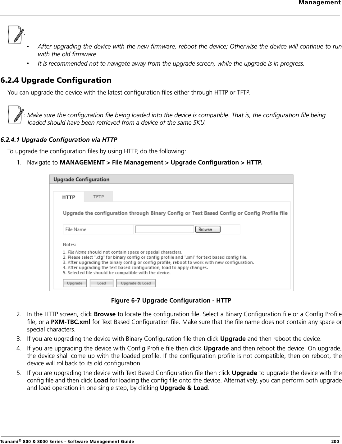
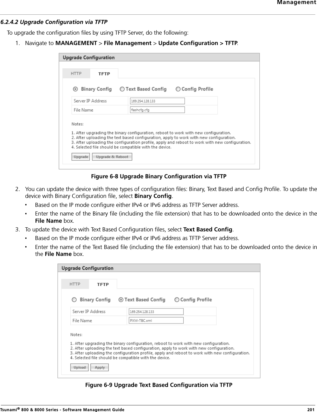
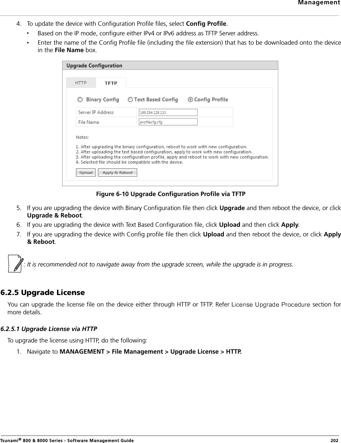
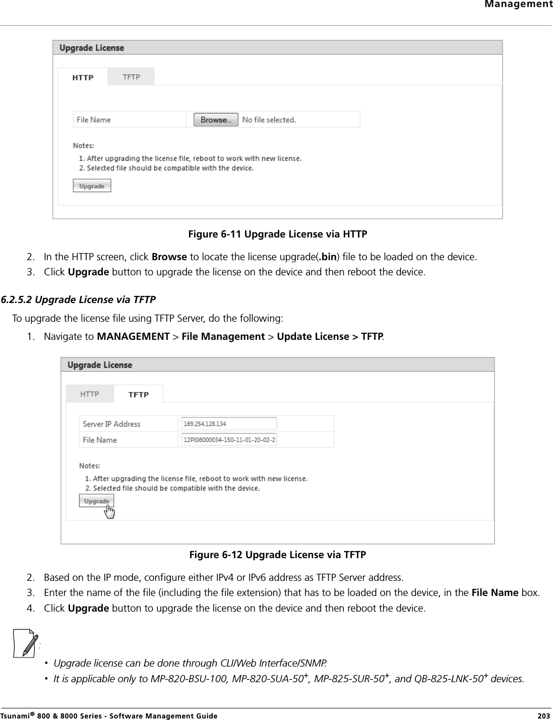
XB92WLE User Manual
>
software guide2
Contents
1.
User Manual
2.
Software guide1
3.
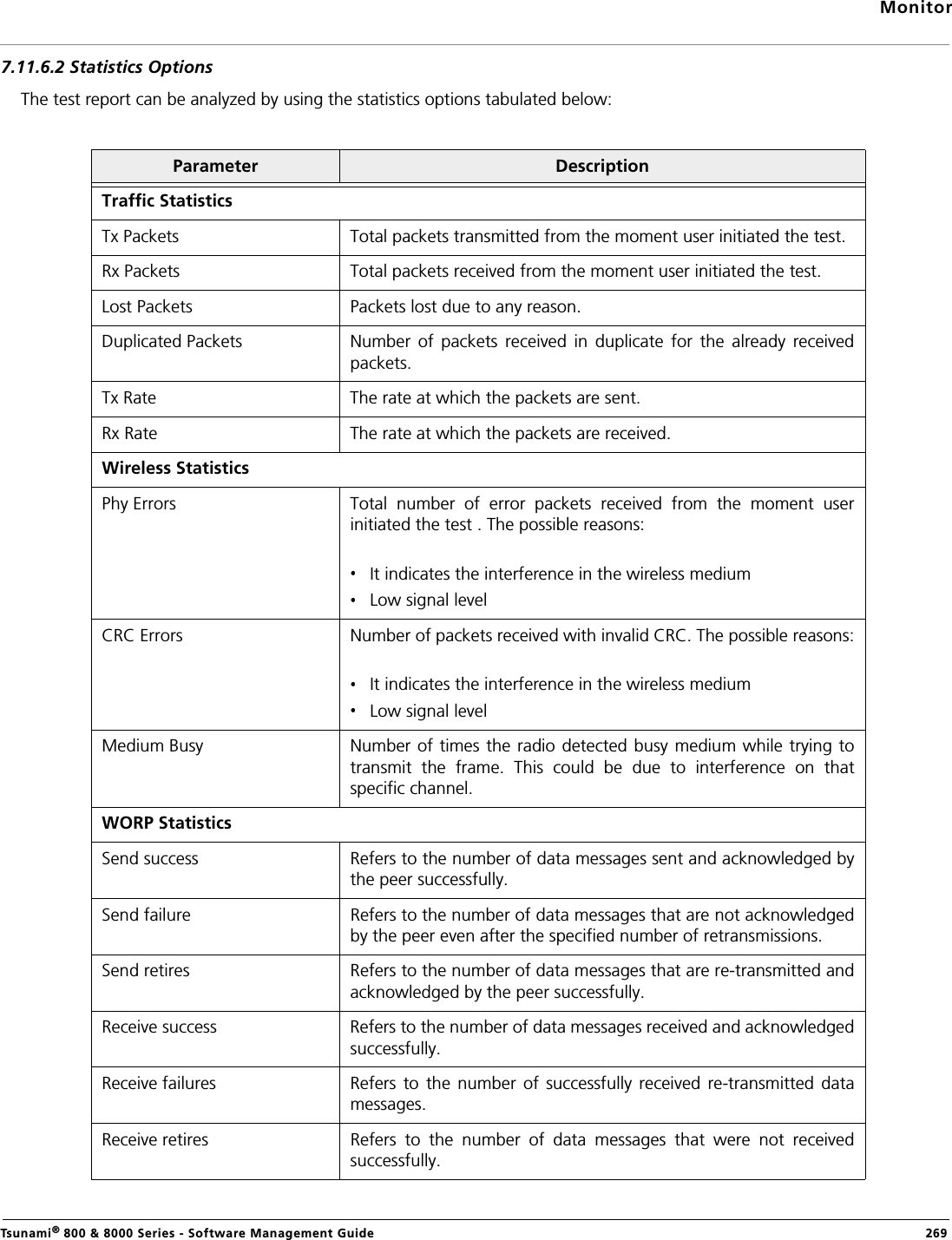
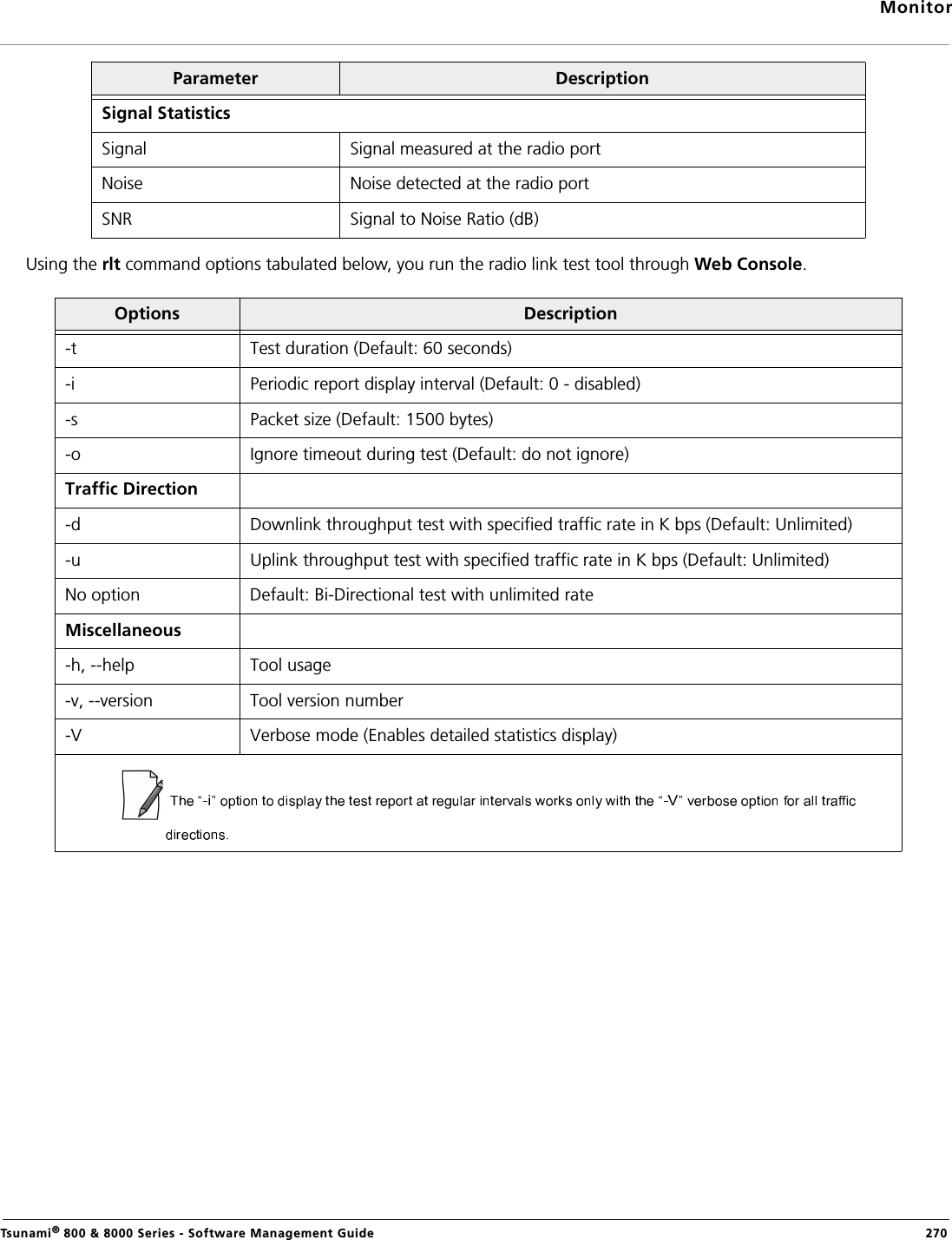
software guide2
4.
Antenna installation guide
5.
EIRP compliance declaration revised
6.
HW_guide_revised
software guide2
Navigation menu
Upload a User Manual
Namespaces
Wiki Guide
HTML
PDF
Info
Views
User Manual
Discussion / Help
Navigation
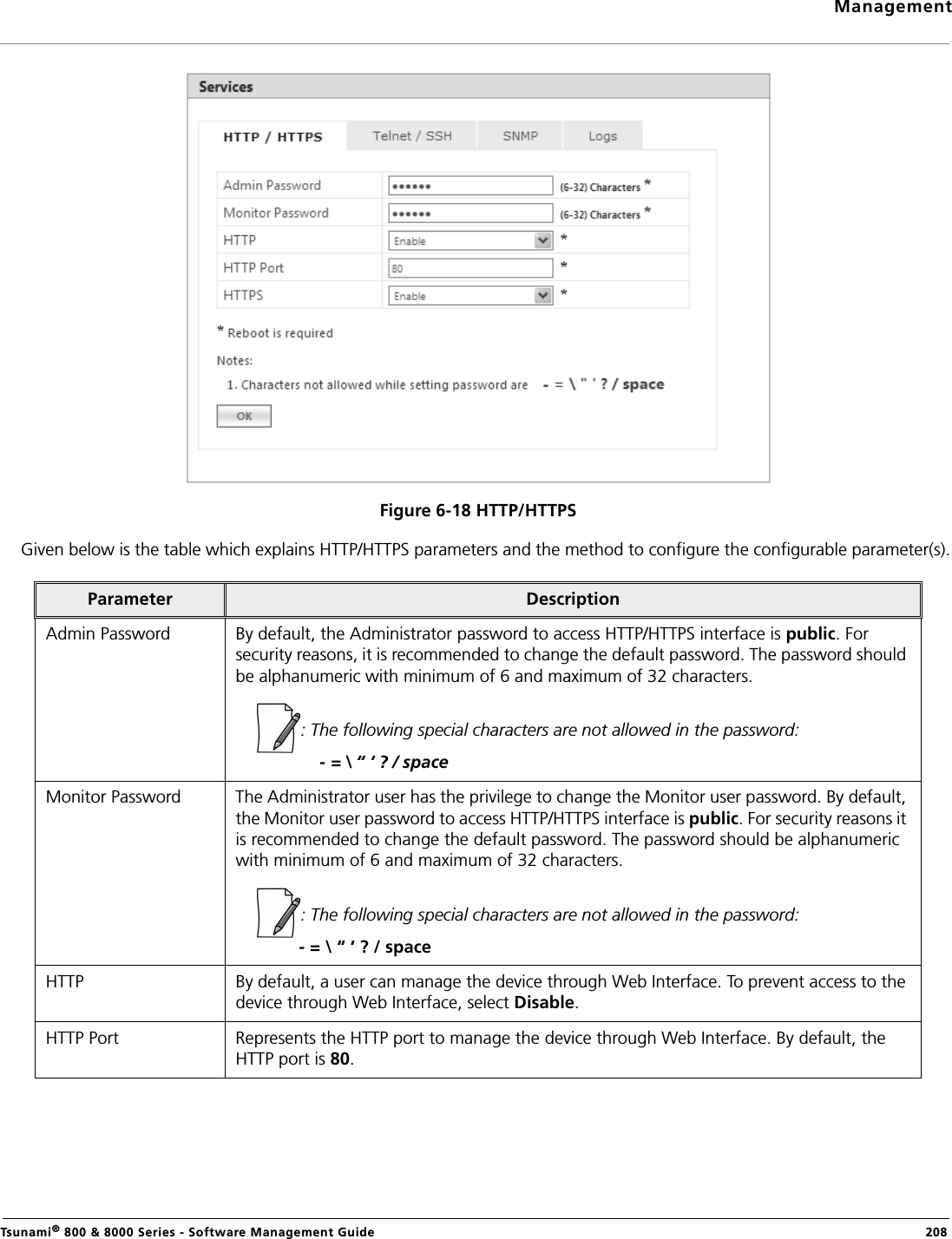
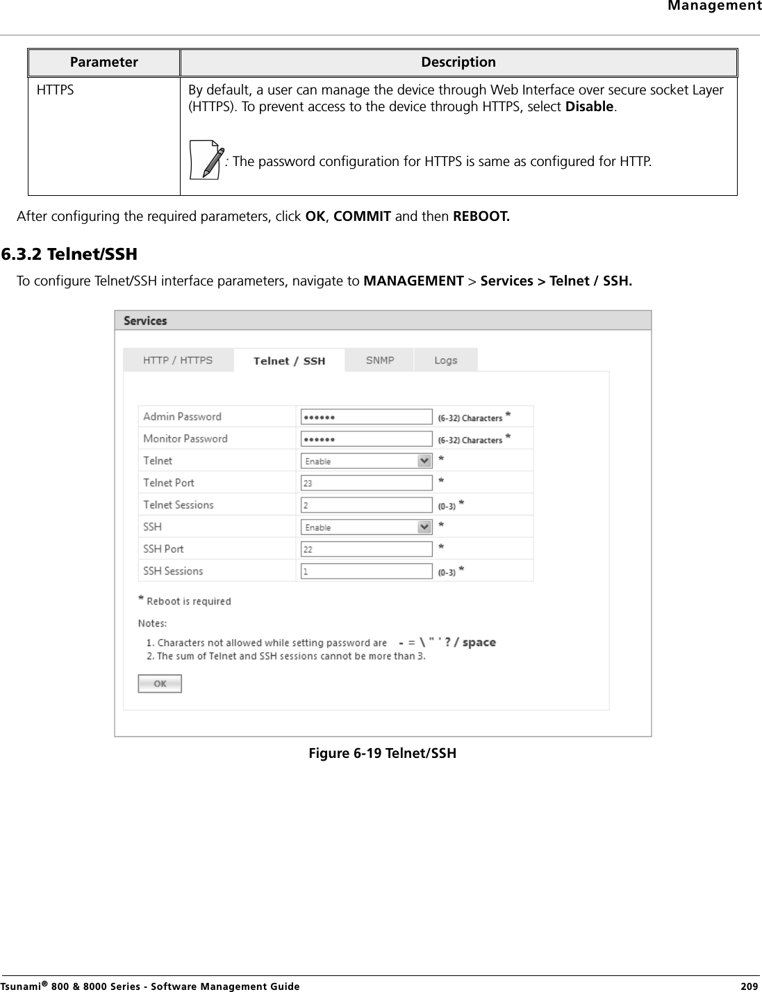
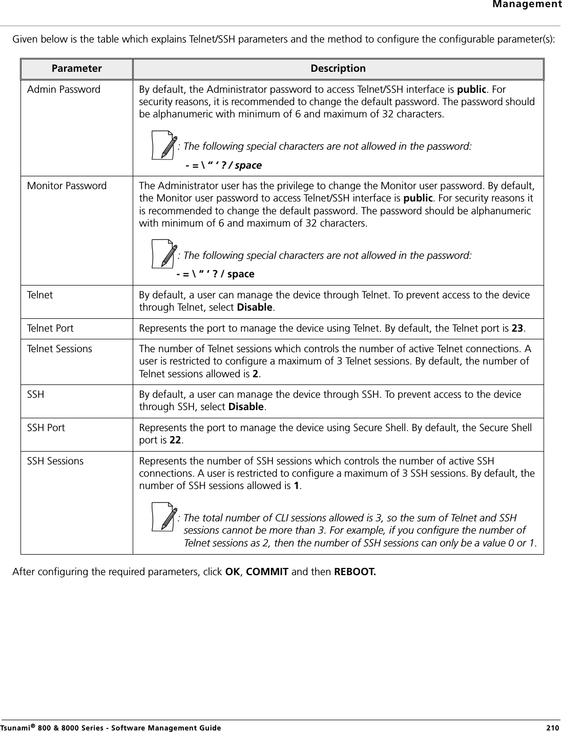
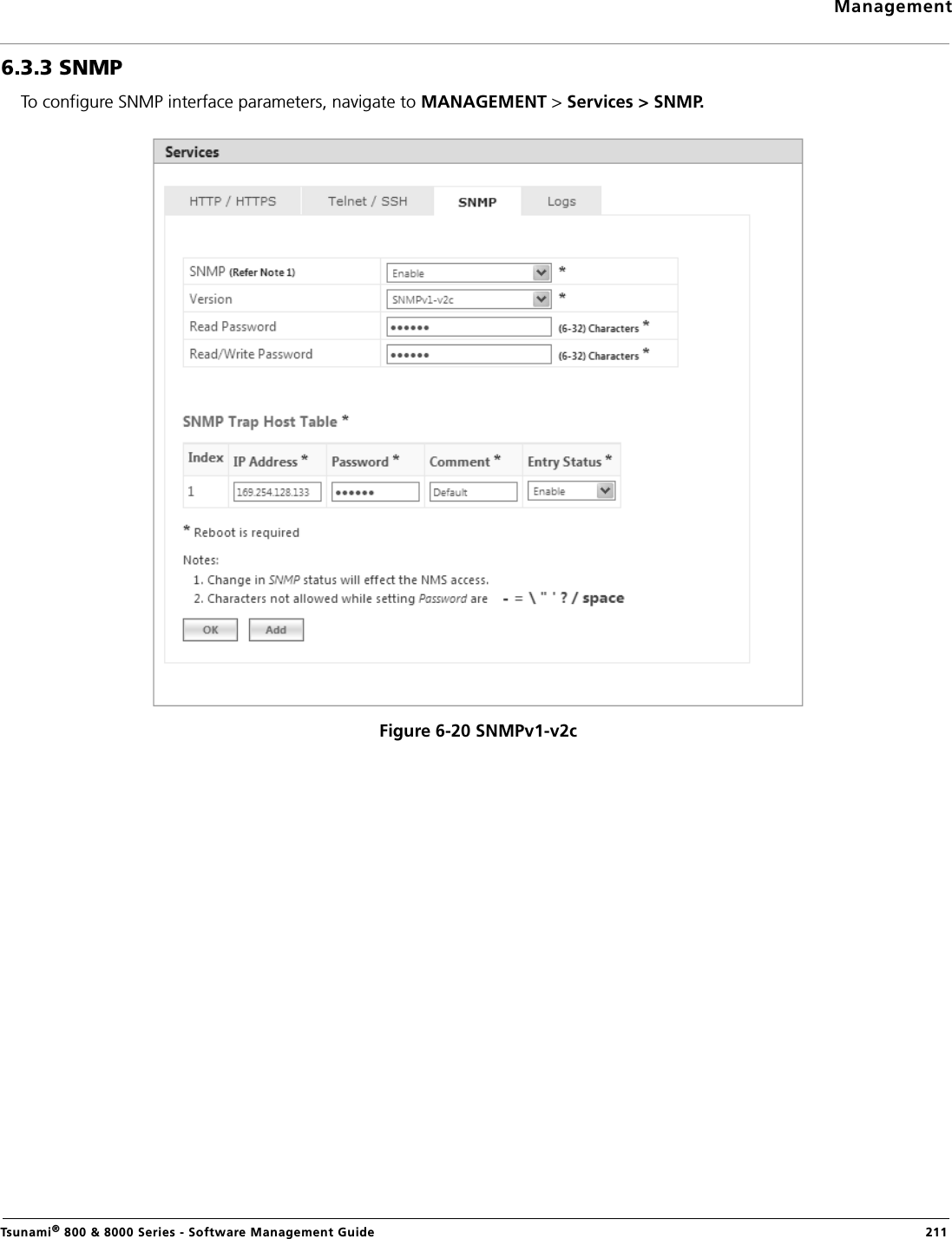
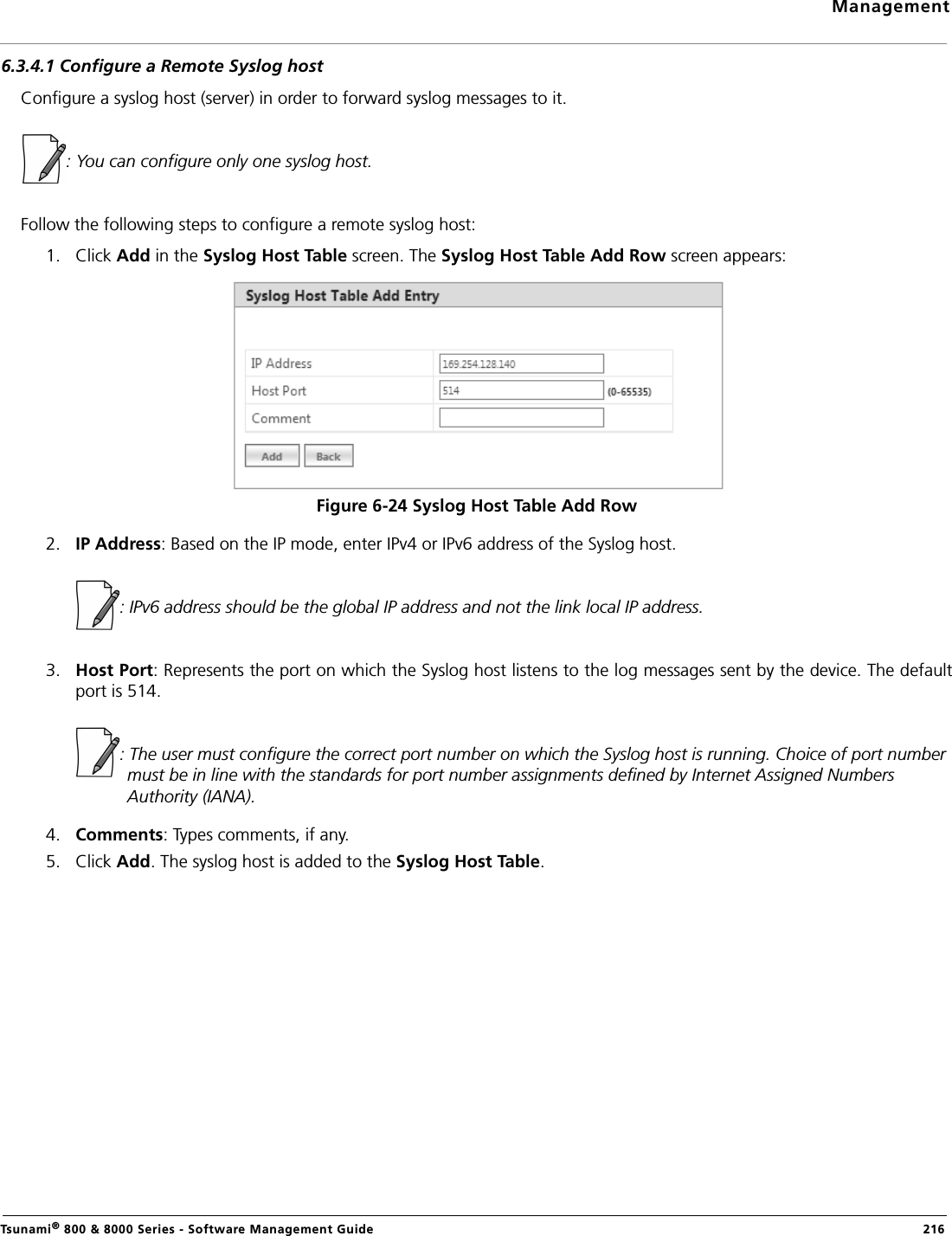
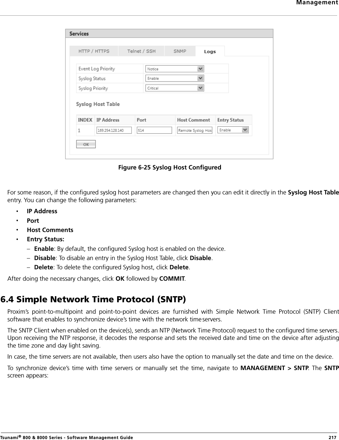
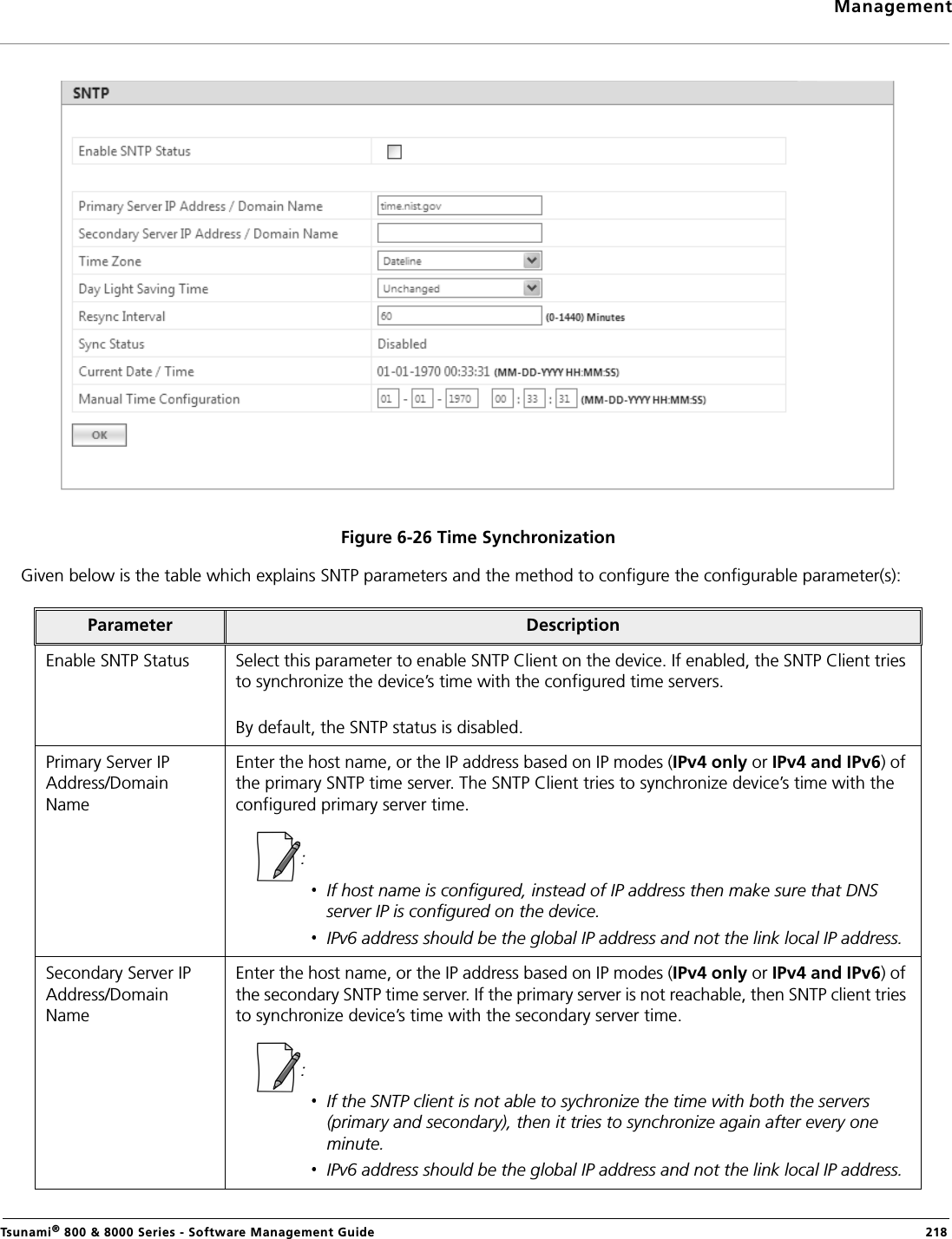
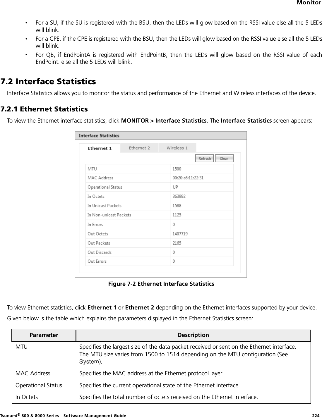
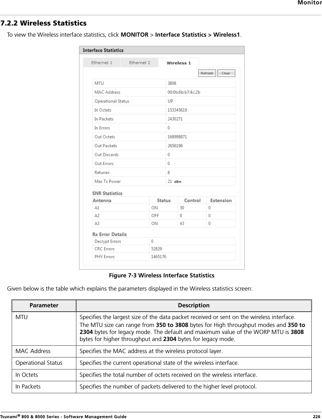

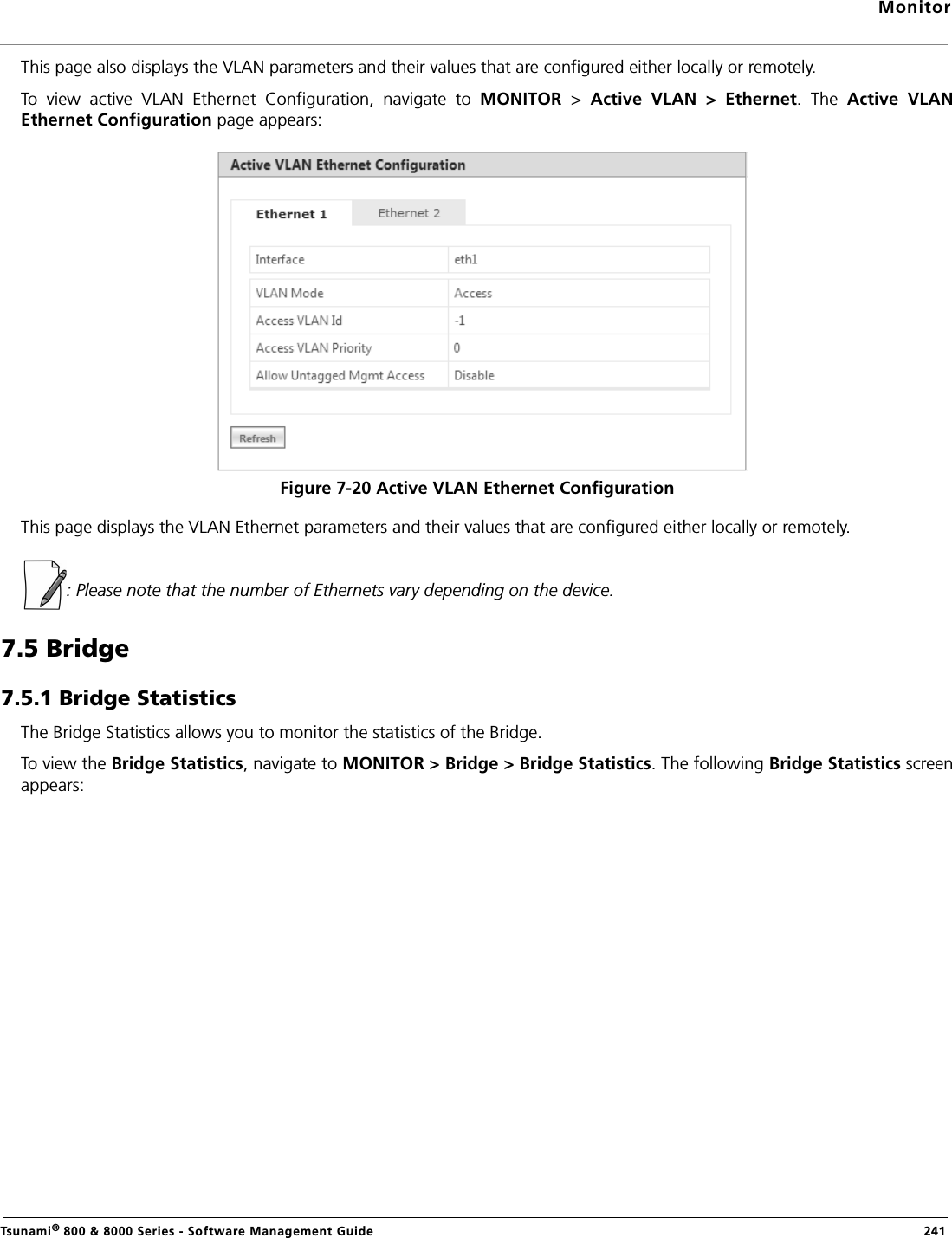
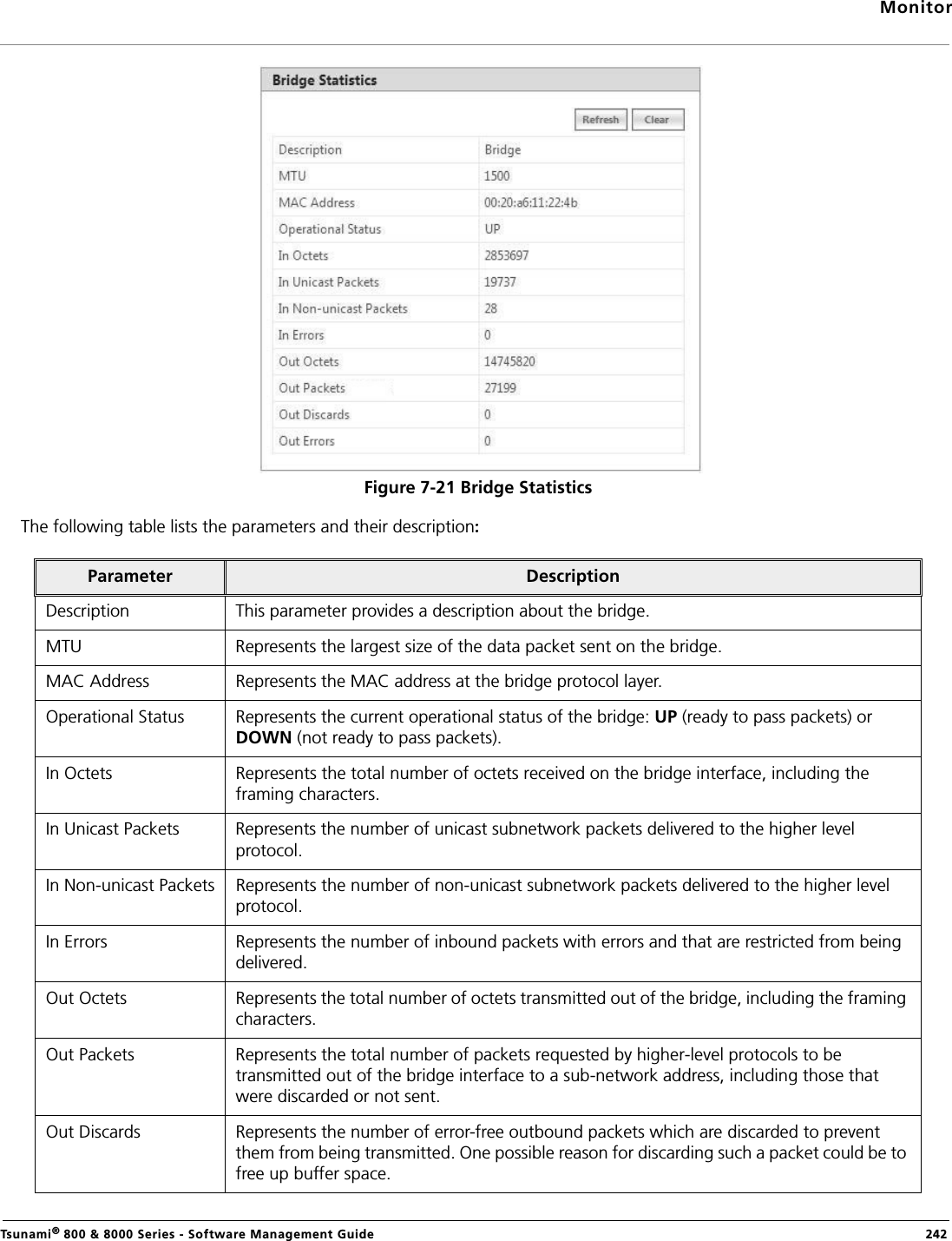
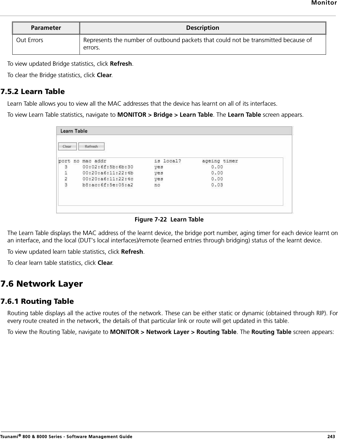
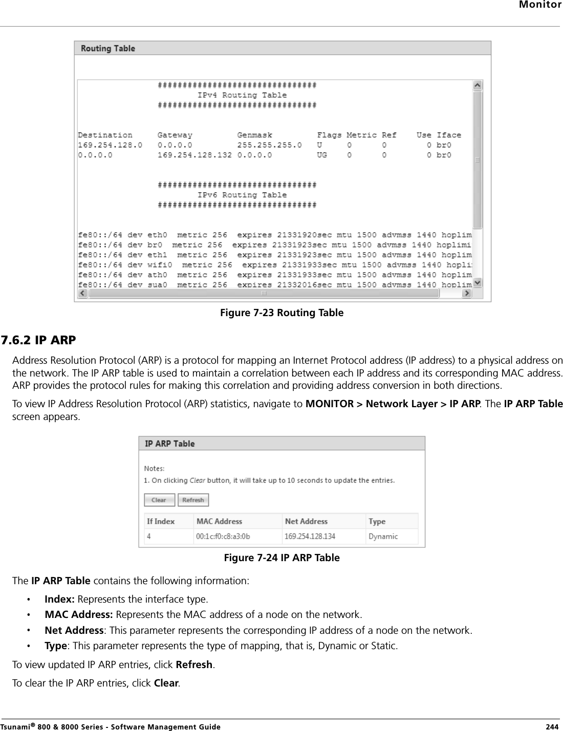
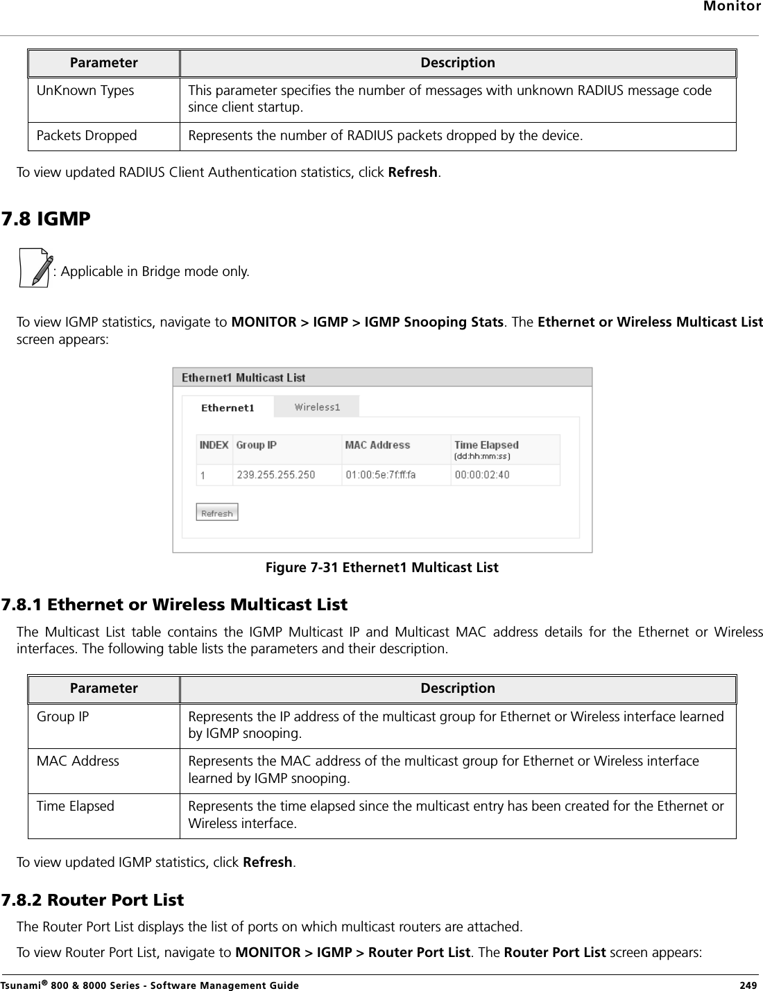
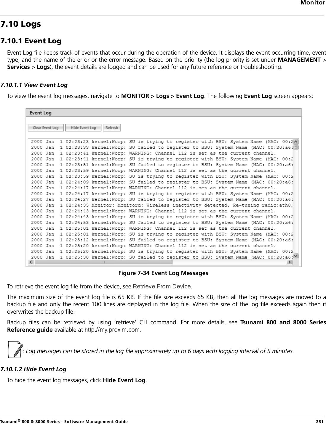
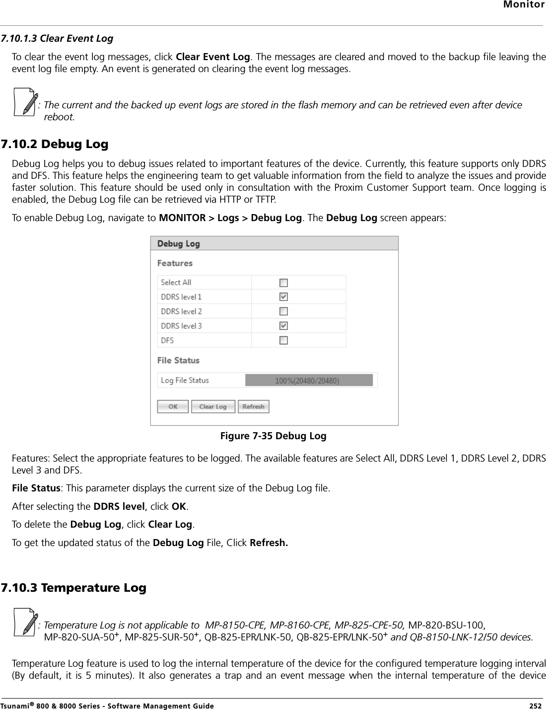
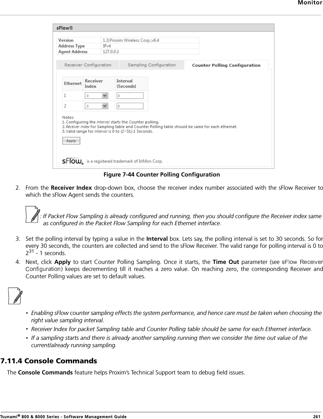
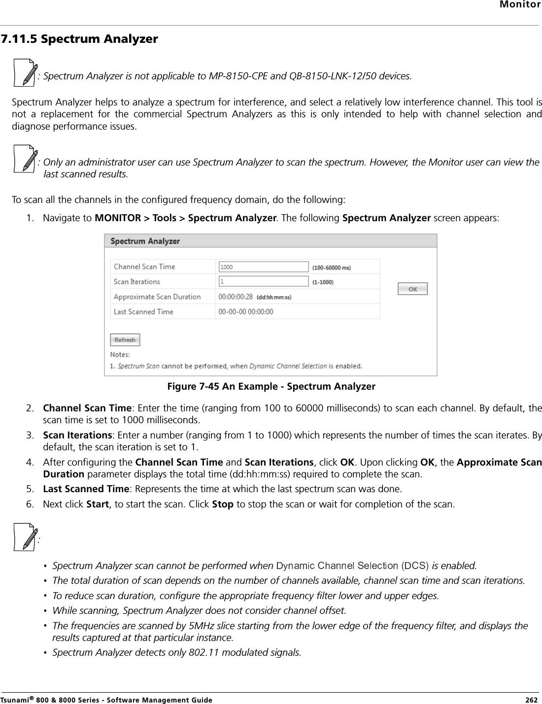
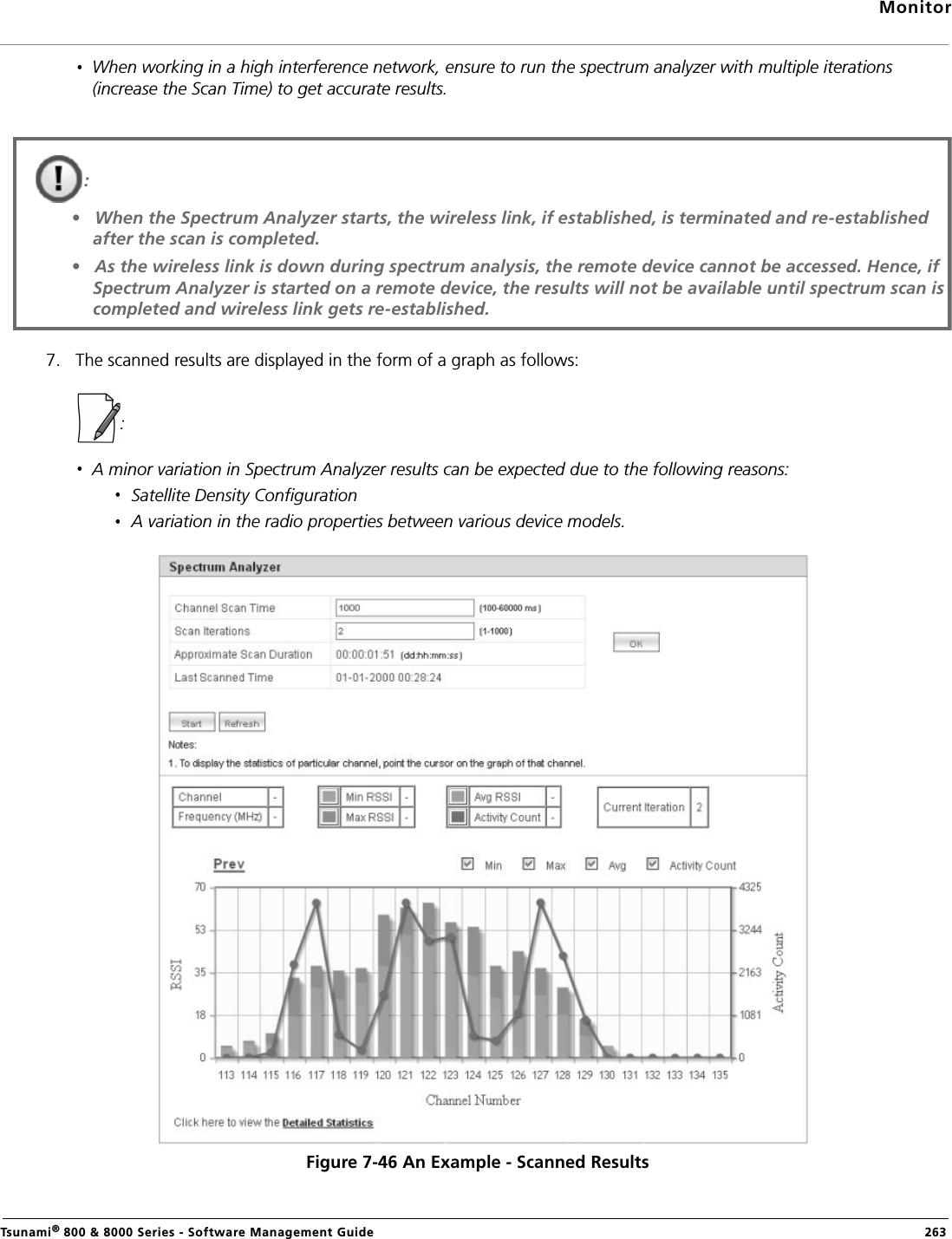
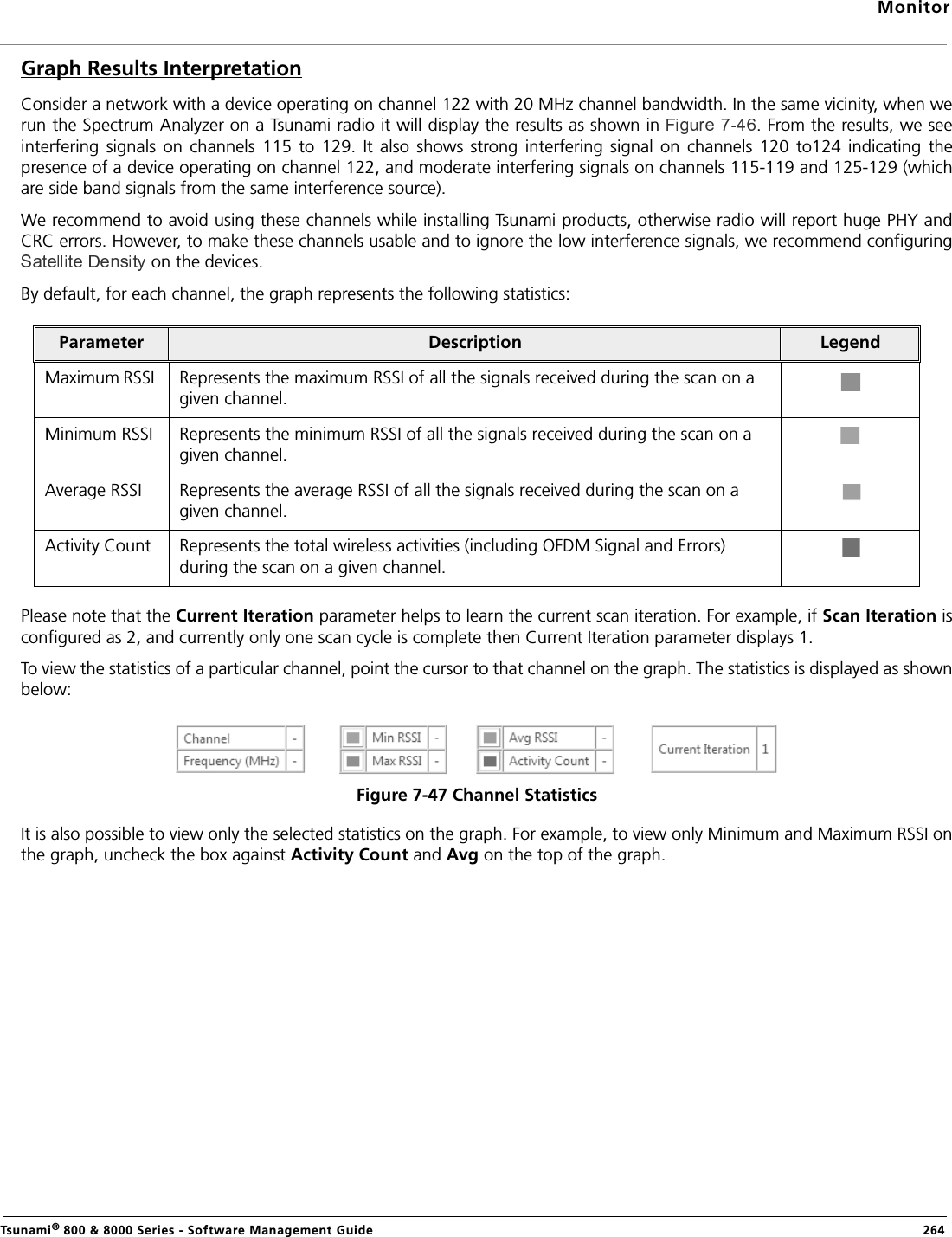
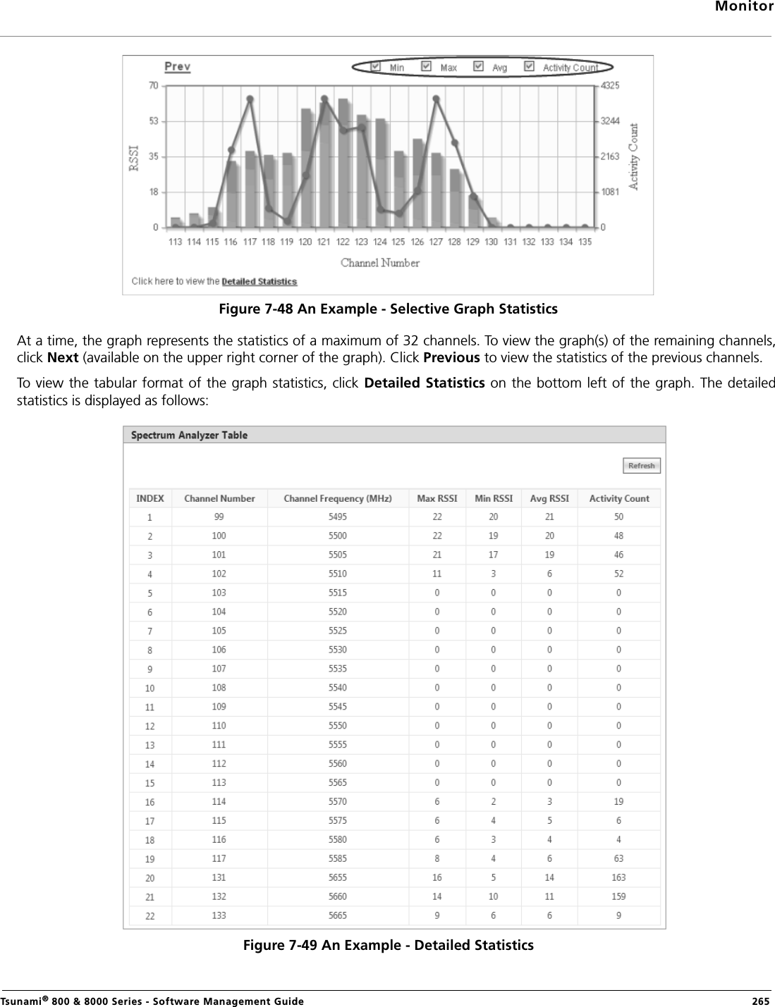
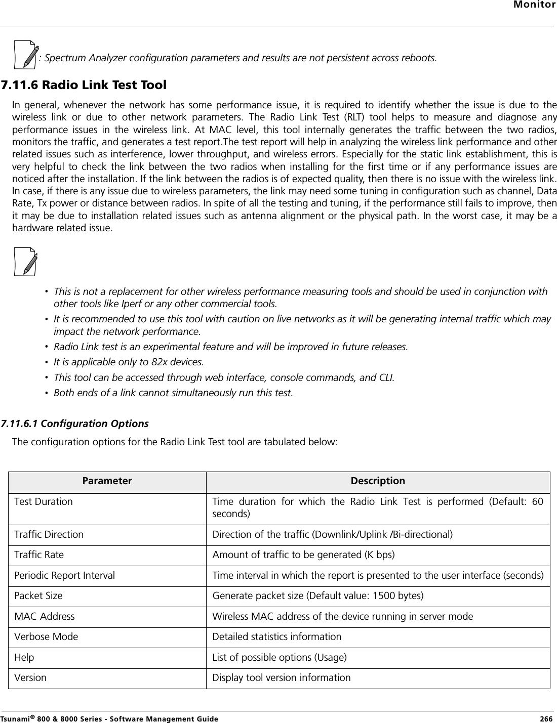
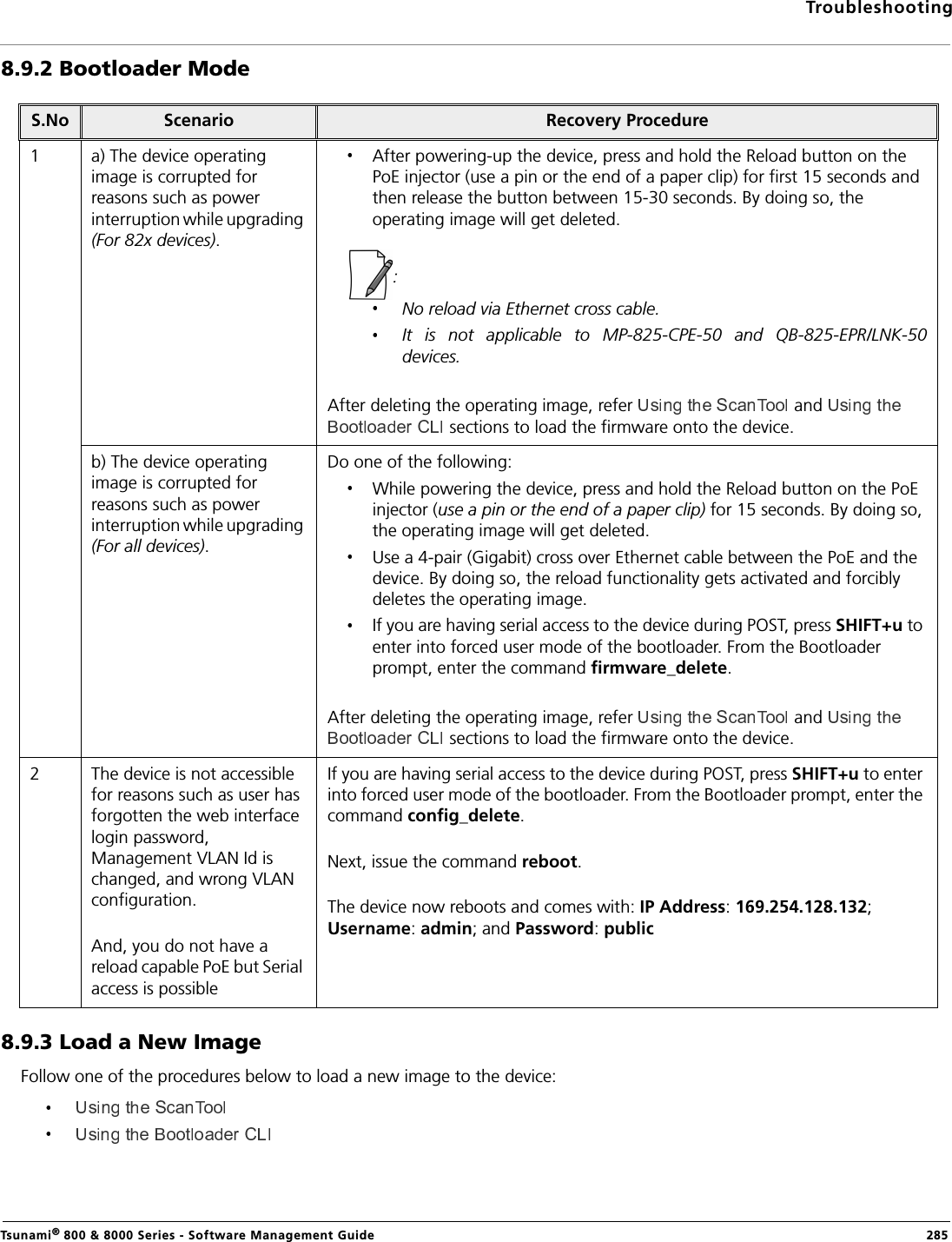
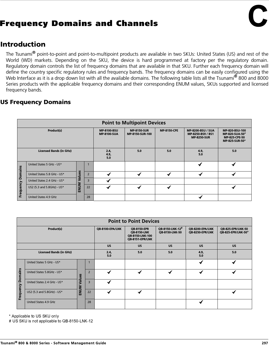
![BSU RedundancyTsunami® 800 & 8000 Series - Software Management Guide 316Log Samples for BSU Redundancy SU - During Boot UpChannel 160 is set as the current channel.SU is trying to register with BSU: BSU1 (MAC: 00:0b:6b:b7:4c:26).SU received QoS Class: Unlimited Best Effort (indx: 1).SU registered with BSU: BSU1 (MAC: 00:0b:6b:b7:4c:26) on channel 160(0x14004A0) (SNR: A1:46 A2:0 A3:40[dB]) at WORP port[ 0 ].Link Profile Index: 1.Wireless: WORP Link Established with Primary BSU: BSU1Wireless: SU discovered Secondary BSU:BSU2 on channel:60After getting connected to the Primary BSU, the SU should discover the secondary BSU.Primary BSU Down - Connected to Secondary BSUSU unregistered from BSU: BSU1 (MAC: 00:0b:6b:b7:4c:26).Channel 60 is set as the current channel.SU is trying to register with BSU: BSU2 (MAC: 00:0b:6b:b7:4b:ff).SU received QoS Class: Unlimited Best Effort (indx: 1).SU registered with BSU: BSU2 (MAC: 00:0b:6b:b7:4b:ff) on channel 60(0x78043C) (SNR: A1:51 A2:0 A3:49[dB]) at WORP port[ 0 ].kernel:Worp: Link Profile Index: 1.Wireless: WORP Link Established with Secondary BSU: BSU2Connected to Other BSU01:52:25 kernel:Worp: WARNING: Channel 100 is set as the current channel.01:52:25 kernel:Worp: SU is trying to register with BSU: BSU3 (MAC: 00:20:a6:d3:ed:e5).01:52:25 kernel:Worp: SU received QoS Class: Unlimited Best Effort (index: 1).01:52:25 kernel:Worp: SU registered with BSU: BSU3 (MAC: 00:20:a6:d3:ed:e5) on channel 100(0xC80464) (SNR: A1:58 A2:0 A3:54[dB]) at WORP port[ 0 ].01:52:25 kernel:Worp: Link Profile Index: 1.01:52:25: Wireless: WORP Link Established with Other BSU: BSU301:54:35: Wireless: SU discovered Secondary BSU:BSU2 on channel:6001:54:35: Wireless: SU discovered Primary BSU:BSU1 on channel:160SU should discover both the Primary and the Secondary BSU, and connect to the Primary BSU after the switch time interval. BSU Switch Time Interval - 15 Minutes1Wireless: WORP Link Established with Secondary BSU: BSU200:08:34: Wireless: SU discovered Primary BSU:BSU1 on channel:16000:23:34 kernel:Worp: SU unregistered from BSU: BSU2 (MAC: 00:0b:6b:b7:4b:ff).00:23:34 kernel:Worp: WARNING: Channel 0 is set as the current channel.00:23:35 kernel:Worp: SU is trying to register with BSU: BSU1 (MAC: 00:0b:6b:b7:4c:26).00:23:35 kernel:Worp: SU received QoS Class: Unlimited Best Effort (indx: 1).](https://usermanual.wiki/Proxim-Wireless/XB92WLE.software-guide2/User-Guide-2355966-Page-146.png)
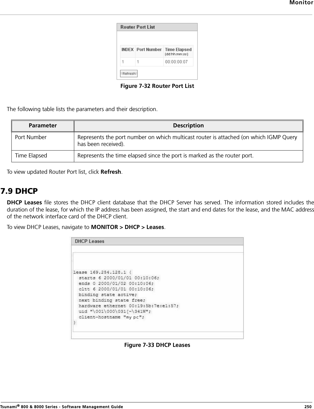
![BSU RedundancyTsunami® 800 & 8000 Series - Software Management Guide 31700:23:35 kernel:Worp: SU registered with BSU: BSU1 (MAC: 00:0b:6b:b7:4c:26) on channel 160(0x14004A0) (SNR: A1:43 A2:0 A3:36[dB]) at WORP port[ 0 ].00:23:35 kernel:Worp: Link Profile Index: 1.00:23:35: Wireless: WORP Link Established with Primary BSU: BSU100:24:34: Wireless: SU discovered Secondary BSU:BSU2 on channel:60Connect to Primary BSU01:59:25: Wireless: WORP Link Established with Other BSU: BSU302:02:25 kernel:Worp: SU unregistered from BSU: BSU3 (MAC: 00:20:a6:d3:ed:e5)..02:02:25: Wireless: SU discovered Secondary BSU:BSU2 on channel:6002:02:25: Wireless: SU discovered Primary BSU:BSU1 on channel:16002:02:25 kernel:Worp: SU is trying to register with BSU: BSU2 (MAC: 00:0b:6b:b7:4b:ff).02:02:25 kernel:Worp: SU received QoS Class: Unlimited Best Effort (indx: 1).02:02:25 kernel:Worp: SU registered with BSU: BSU2 (MAC: 00:0b:6b:b7:4b:ff) on channel 60(0x78043C) (SNR: A1:37 A2:0 A3:35[dB]) at WORP port[ 0 ].02:02:25: Wireless: WORP Link Established with Secondary BSU: BSU202:04:25 kernel:Worp: SU unregistered from BSU: BSU2 (MAC: 00:0b:6b:b7:4b:ff).02:04:25 kernel:Worp: SU is trying to register with BSU: BSU1 (MAC: 00:0b:6b:b7:4c:26).02:04:25 kernel:Worp: SU registered with BSU: BSU1 (MAC: 00:0b:6b:b7:4c:26) on channel 160(0x14004A0) (SNR: A1:46 A2:0 A3:42[dB]) at WORP port[ 0 ].02:05:25: Wireless: SU discovered Secondary BSU:BSU2 on channel:60 02:04:25: Wireless: WORP Link Established with Primary BSU: BSU1No Response Message03:32:25 kernel:Worp: WARNING: Channel 0 is set as the current channel.03:32:25 kernel:Worp: SU is trying to register with BSU: BSU1 (MAC: 00:0b:6b:b7:4c:26).03:32:25 kernel:Worp: SU received QoS Class: Unlimited Best Effort (indx: 1).03:32:25 kernel:Worp: SU registered with BSU: BSU1 (MAC: 00:0b:6b:b7:4c:26) on channel 160(0x14004A0) (SNR: A1:45 A2:0 A3:42[dB]) at WORP port[ 0 ].03:32:25 kernel:Worp: Link Profile Index: 1.03:32:25: Wireless: WORP Link Established with Primary BSU: BSU103:33:25: Wireless: SU discovered Secondary BSU:BSU2 on channel:6003:40:43: Wireless: Secondary BSU: BSU2 not Available](https://usermanual.wiki/Proxim-Wireless/XB92WLE.software-guide2/User-Guide-2355966-Page-147.png)