Proxim Wireless XB92WLE 802.11 a/n PCIe Module User Manual Tsunami800 8000 SW Guide v5 2 SW2 6 2
Proxim Wireless Corporation 802.11 a/n PCIe Module Tsunami800 8000 SW Guide v5 2 SW2 6 2
Contents
software guide2
Advanced Configuration
Tsunami® 800 & 8000 Series - Software Management Guide 171
Given below is the table which explains Protocol Filter parameters and the method to configure the configurable
parameter(s):
After configuring the required parameters, click OK and then COMMIT.
5.10.1.1 Protocol Filter Table
The Protocol Filter table displays a list of default protocols supported by the device and the protocols created by the user. By
default, the system generates 19 protocols entries. Each of the Protocol contains the following information:
Parameter Description
Filtering Control This parameter is used to apply filters on the device’s interface. The filtering can be applied
on any of the following interfaces:
Ethernet: Packets are examined at the Ethernet interface.
Wireless: Packets are examined at the Wireless interface.
All Interfaces: Packets are examined at both Ethernet and Wireless interface.
By default, the Filtering Control is set to Disable, meaning which Protocol Filters are
disabled on all the interfaces.
: In addition to enabling Filtering Control, the Global Filter Flag should also be
enabled to apply filters.
Filtering Type This parameter specifies the action to be performed on the data packets whose protocol
type is not defined in the protocol filter table (this table contains a list of default protocols
supported by the device and the protocols defined by the user), or whose Entry Status is in
Disable state. The available filtering types are:
Block: The protocols with entry status Disable or the protocols which do not exist in
the protocol filtering table are blocked.
Passthru: The protocols with entry status Disable or the protocols which do not exist
in the protocol filtering table are allowed through the configured interface.
Parameter Description
Protocol Name Represents the Protocol name. The system throws an error when you try to edit the name
of a default protocol.
Protocol Number Represents the Protocol number. The value is of 4 digit hexadecimal format. The system
throws an error when you try to edit the Protocol number of a default protocol.
Filter Status The supported filter status are,
Passthru: When the filter status is set to Passthru and entry status is Enable, all
packets whose protocol matches with the given protocol number are forwarded on
the configured interface.
Block: When the filter status is set to Block and entry status is Enable, all packets
whose protocol matches with the given protocol number are dropped on the
configured interface.
By default, the status is set to Block.
Advanced Configuration
Tsunami® 800 & 8000 Series - Software Management Guide 172
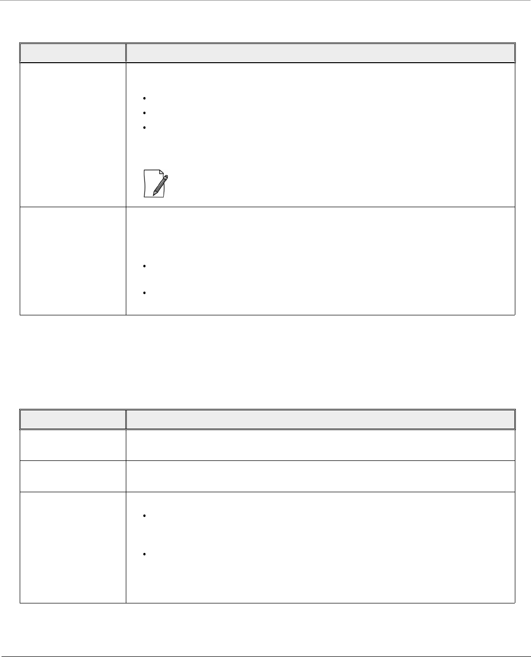
5.10.1.2 Add User-defined Protocols to the Filter Table
To add user-defined protocols to the Protocol Filter Table, click Add in the Protocol Filter screen. The Protocol Filter Add
Row screen appears.
Figure 5-95 Add User-defined Protocols
Enter details for all the required parameters and click Add.
: The maximum number of Protocol Filters that can be added to the table are 64, out of which 19 are default entries.
5.10.2 Static MAC Address Filter
The Static MAC Address filter optimizes the performance of a wireless (and wired) network. With this feature configured, the
device can block traffic between wired devices and wireless devices based on the MAC address.
Each MAC Address or Mask is comprised of 12 hexadecimal digits (0-9, A-F) that correspond to a 48-bit identifier. (Each
hexadecimal digit represents 4 bits (0 or 1)).
Taken together, a MAC Address/Mask pair specifies an address or a range of MAC addresses that the device will look for
when examining packets. The device uses Boolean logic to perform an “AND” operation between the MAC Address and the
Mask at the bit level. A Mask of 00:00:00:00:00:00 corresponds to all MAC addresses, and a Mask of FF:FF:FF:FF:FF:FF applies
only to the specified MAC Address.
For example, if the MAC Address is 00:20:A6:12:54:C3 and the Mask is FF:FF:FF:00:00:00, the device will examine the source
and destination addresses of each packet looking for any MAC address starting with 00:20:A6. If the Mask is FF:FF:FF:FF:FF:FF,
the device will only look for the specific MAC address (in this case, 00:20:A6:12:54:C3).
You can configure the Static MAC Address Filter parameters depending on the following scenarios:
To prevent all traffic from a specific wired MAC address from being forwarded to the wireless network, configure only
the Wired MAC Address and Wired Mask (leave the Wireless MAC Address and Wireless Mask set to all zeros).
Entry Status Set the entry status as either Enable, Disable or Delete.
Enable: Enables filter status on a protocol.
Disable: Disables filter status on a protocol.
Delete: Deletes a protocol entry from the Protocol Filter Table.
: System-defined default protocols cannot be deleted.

Advanced Configuration
Tsunami® 800 & 8000 Series - Software Management Guide 173
To prevent all traffic from a specific wireless MAC address from being forwarded to the wired network, configure only
the Wireless MAC address and Wireless Mask (leave the Wired MAC Address and Wired Mask set to all zeros).
To prevent traffic between a specific wired MAC address and a specific wireless MAC address, configure all four
parameters. Configure the wired and wireless MAC address and set the wired and wireless mask to all Fs.
To prevent all traffic from a specific wired Group MAC address from being forwarded to the wireless network,
configure only the Wired MAC Address and Wired Mask (leave the Wireless MAC Address and Wireless Mask set to all
zeros).
To prevent all traffic from a specific wireless Group MAC address from being forwarded to the wired network,
configure only the Wireless MAC address and Wireless Mask (leave the Wired MAC Address and Wired Mask set to all
zeros).
To prevent traffic between a specific wired Group MAC address and a specific wireless Group MAC address, configure
all four parameters. Configure the wired and wireless MAC address and set the wired and wireless mask to all Fs.
Static MAC Filter Examples
Consider a network that contains a wired PC and three wireless PCs. The MAC addresses for each PCs are as follows:
MAC Address of the wired PC: 00:40:F4:1C:DB:6A
MAC Address of the wireless PC1: 00:02:2D:51:94:E4
MAC Address of the wireless PC2: 00:02:2D:51:32:12
MAC Address of the wireless PC3: 00:20:A6:12:4E:38
5.10.2.0.1 Prevent two specific PCs from communicating
Configure the following settings to prevent the wired PC and wireless PC1 from communicating:
Wired MAC Address: 00:40:F4:1C:DB:6A
Wired Mask: FF:FF:FF:FF:FF:FF
Wireless MAC Address: 00:02:2D:51:94:E4
Wireless Mask: FF:FF:FF:FF:FF:FF
Result: Traffic between the wired PC and wireless PC1 is blocked. wireless PC2 and PC3 can still communicate with the wired
PC.
5.10.2.0.2 Prevent multiple Wireless PCs from communicating with a single wired PC
Configure the following settings to prevent wireless PC1 and PC2 from communicating with the wired PC:
Wired MAC Address: 00:40:F4:1C:DB:6A
Wired Mask: FF:FF:FF:FF:FF:FF
Wireless MAC Address: 00:02:2D:51:94:E4
Wireless Mask: FF:FF:FF:00:00:00
Result: When a logical “AND” is performed on the Wireless MAC Address and Wireless Mask, the result corresponds to any
MAC address beginning with the 00:20:2D prefix. Since wireless PC1 and wireless PC2 share the same prefix (00:02:2D),
traffic between the wired Server and wireless PC1 and PC2 is blocked. Wireless PC3 can still communicate with the wired PC
since it has a different prefix (00:20:A6).
5.10.2.0.3 Prevent all wireless PCs from communicating with a single wired PC
Configure the following settings to prevent wired PC from communicating with all three wireless PCs:
Wired MAC Address: 00:40:F4:1C:DB:6A
Wired Mask: FF:FF:FF:FF:FF:FF
Wireless MAC Address: 00:00:00:00:00:00
Wireless Mask: 00:00:00:00:00:00
Advanced Configuration
Tsunami® 800 & 8000 Series - Software Management Guide 174
Result: The device blocks all traffic between the wired PC and all wireless PCs.
5.10.2.0.4 Prevent a wireless PC from communicating with the wired network
Configure the following settings to prevent wireless PC3 from communicating with any device on the Ethernet:
Wired MAC Address: 00:00:00:00:00:00
Wired Mask: 00:00:00:00:00:00
Wireless MAC Address: 00:20:A6:12:4E:38
Wireless Mask: FF:FF:FF:FF:FF:FF
Result: The device blocks all traffic between wireless PC3 and the Ethernet network.
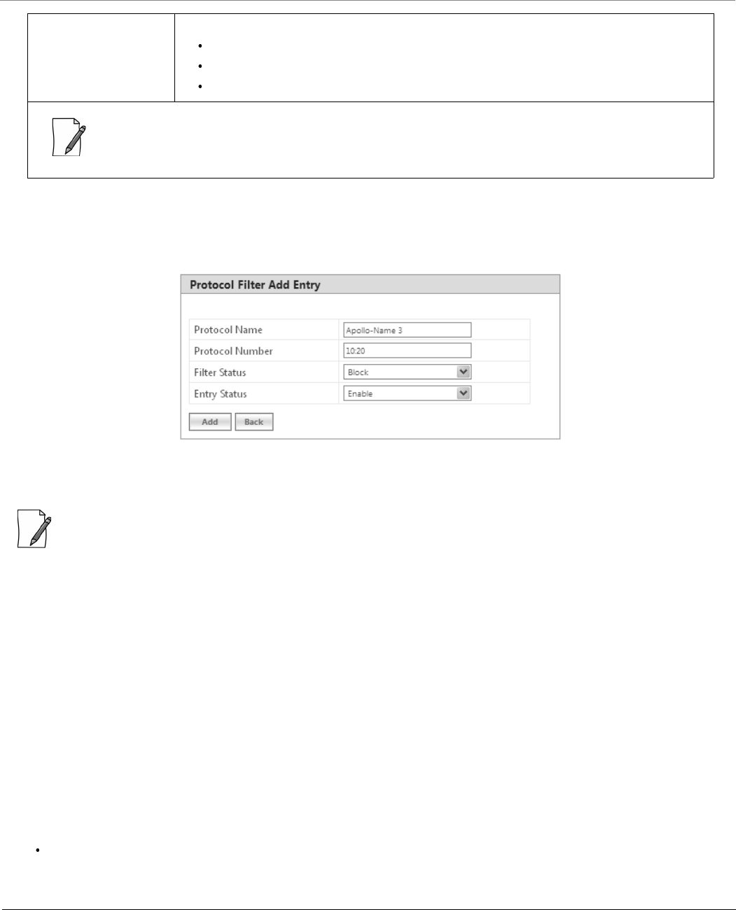
5.10.2.1 Static MAC Address Filter Configuration
To configure Static MAC Filter parameters, navigate to ADVANCED CONFIGURATION > Filtering > Static MAC Address
Filter. The Static MAC Address Filter screen appears:
Figure 5-96 Static MAC Address Filter
Click Add in the Static MAC Address Filter screen. The Static MAC Address Filter Add Row screen appears.
Figure 5-97 Static MAC Address Filter Add Entry
Advanced Configuration
Tsunami® 800 & 8000 Series - Software Management Guide 175
Given below is the table which explains Static MAC Address Filter parameters and the method to configure the configurable
parameter(s):
Click Add and then COMMIT.
:
You can configure a maximum of 200 MAC address filters.
The Wired MAC address and the Wireless MAC address should be a unicast MAC address.
The MAC Address or Mask includes 12 hexadecimal digits (each hexadecimal equals to 4 bits containing 0 or 1)
which is equivalent to 48 bit identifier.
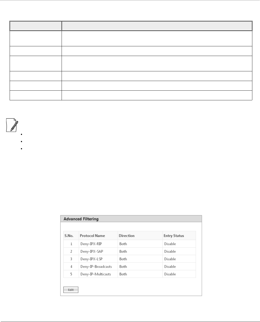
5.10.3 Advanced Filtering
With Advanced Filtering, you can filter pre-defined IP Protocol traffic on the network.
By default, 5 IP protocols are pre-defined and based on the configuration they can be blocked or allowed to enter the
network.
To apply filters on the IP protocols, navigate to ADVANCED CONFIGURATION > Filtering > Advanced Filtering. The
Advanced Filtering screen appears:
Figure 5-98 Advanced Filtering
Parameter Description
Wired MAC Address Specifies the MAC address of the device on the wired network that is restricted from
communicating with a device on the wireless network.
Wired MAC Mask Specifies the range of MAC address to which this filter is to be applied.
Wireless MAC address Specifies the MAC address of the device on the wireless network that is restricted from
communicating with a device on the wired network.
Wireless MAC Mask Specifies the range of MAC address to which this filter is to be applied.
Comment Specifies the comment associated with Static MAC Filter table entry.
Status Specifies the status of the newly created filter.
Advanced Configuration
Tsunami® 800 & 8000 Series - Software Management Guide 176
The Advanced Filtering table contains a list of 5 pre-defined protocols on which Advanced Filtering is applied. The following
table explains the Filtering table parameters:
:
The Advanced Filtering table contains a maximum of 5 pre-defined IP protocols.
User-defined IP protocols cannot be added to the Advanced Filtering table.
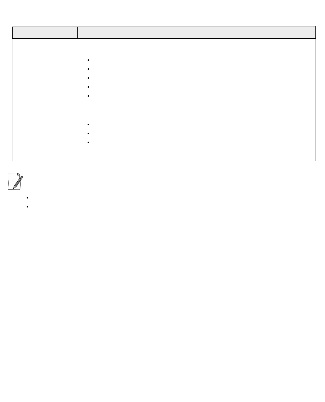
5.10.3.1 Edit Advanced Filtering Table Entries
To edit Advanced Filtering table protocols, click Edit in the Advanced Filtering screen. The Advanced Filtering - Edit
Entries screen appears.
Parameter Description
Protocol Name Represents the protocol name. By default, Advanced Filtering is supported on the
following 5 default protocols:
Deny IPX RIP
Deny IPX SAP
Deny IPX LSP
Deny IP Broadcasts
Deny IP Multicasts
Direction Represents the direction of an IP Protocol traffic that needs to be filtered. The directions
that can be filtered are,
Ethernet to wireless
Wireless to ethernet
Both
Entry Status The filters are applied on the IP protocol only when Entry Status is enabled.
Advanced Configuration
Tsunami® 800 & 8000 Series - Software Management Guide 177
Figure 5-99 Advance Filtering- Edit Entries
Modify the IP protocol traffic direction that needs to be filtered, and the filtering status for the desired IP Protocol.
Next click OK and then COMMIT.
5.10.4 TCP/UDP Port Filter
TCP/UDP Port Filtering allows you to enable or disable Transmission Control Protocol (TCP) ports and User Datagram Port
(UDP) ports on network devices. A user specifies a Protocol Name, Port Number, Port Type (TCP, UDP, or TCP/UDP), and
filtering interfaces (Only Wireless, Only Ethernet or Both) in order to block access to services such as Telnet and FTP, and traffic
such as NETBIOS and HTTP.
To apply filters on TCP/UDP Port, navigate to ADVANCED CONFIGURATION > Filtering > TCP/UDP Port Filter. The
TCP/UDP Port Filter screen appears.
Advanced Configuration
Tsunami® 800 & 8000 Series - Software Management Guide 178
Figure 5-100 TCP/UDP Port Filter
The Filter Control parameters determines if filter has to be applied or not on a TCP/UDP Port. By default, it is disabled. To
apply filters, select Enable and click OK.
5.10.4.1 TCP/UDP Port Filter Table
The TCP/UDP Port Filter table displays a list of default TCP/UDP ports and user-defined ports which can be enabled or disabled
as desired. By default, the device support 7 default TCP/UDP port filter entries.
Parameter Description
Protocol Name Represents the name of the service/protocol. Please note that the system throws an error
when an attempt is made to edit the default service/protocol name.
Port Number Represents the destination port number. Please note that the system throws an error when
an attempt is made to edit the port number.
Port Type Represents the port type (TCP, UDP, Both).
Filter Interface Represents the interface on which the filter is applied. The supported interfaces are,
Only Ethernet
Only Wireless
All Interfaces
Advanced Configuration
Tsunami® 800 & 8000 Series - Software Management Guide 179
If you have configured any user-defined protocols then click OK and then COMMIT.
For example, a device with the following configuration would discard frames received on its Ethernet interface with a UDP
destination port number of 137, effectively blocking NETBIOS Name Service packets. Please note that even the Filtering
Control should be enabled to apply the filter.
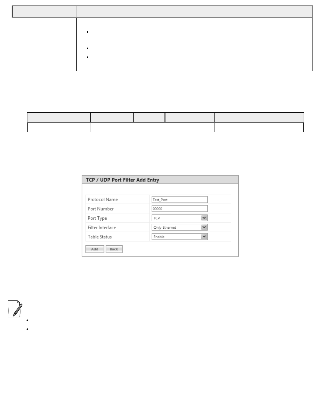
5.10.4.2 Adding User-defined TCP/UDP Port Filter Entries
To add user-defined TCP/UDP port filter entries to the table, click Add in the TCP / UDP Port Filter screen. The TCP/UDP
Port Filter Add Row screen appears:
Figure 5-101 Add User-defined TCP/UDP Protocols
Provide details for all the parameters and click Add.
To apply the configured parameters, click COMMIT.
:
The TCP/UDP filtering operation is allowed only when the Global Flag and Filter Control options are enabled.
You can add a maximum of 64 TCP/UDP Port Filter entries to the table, out of which 7 are default entries.
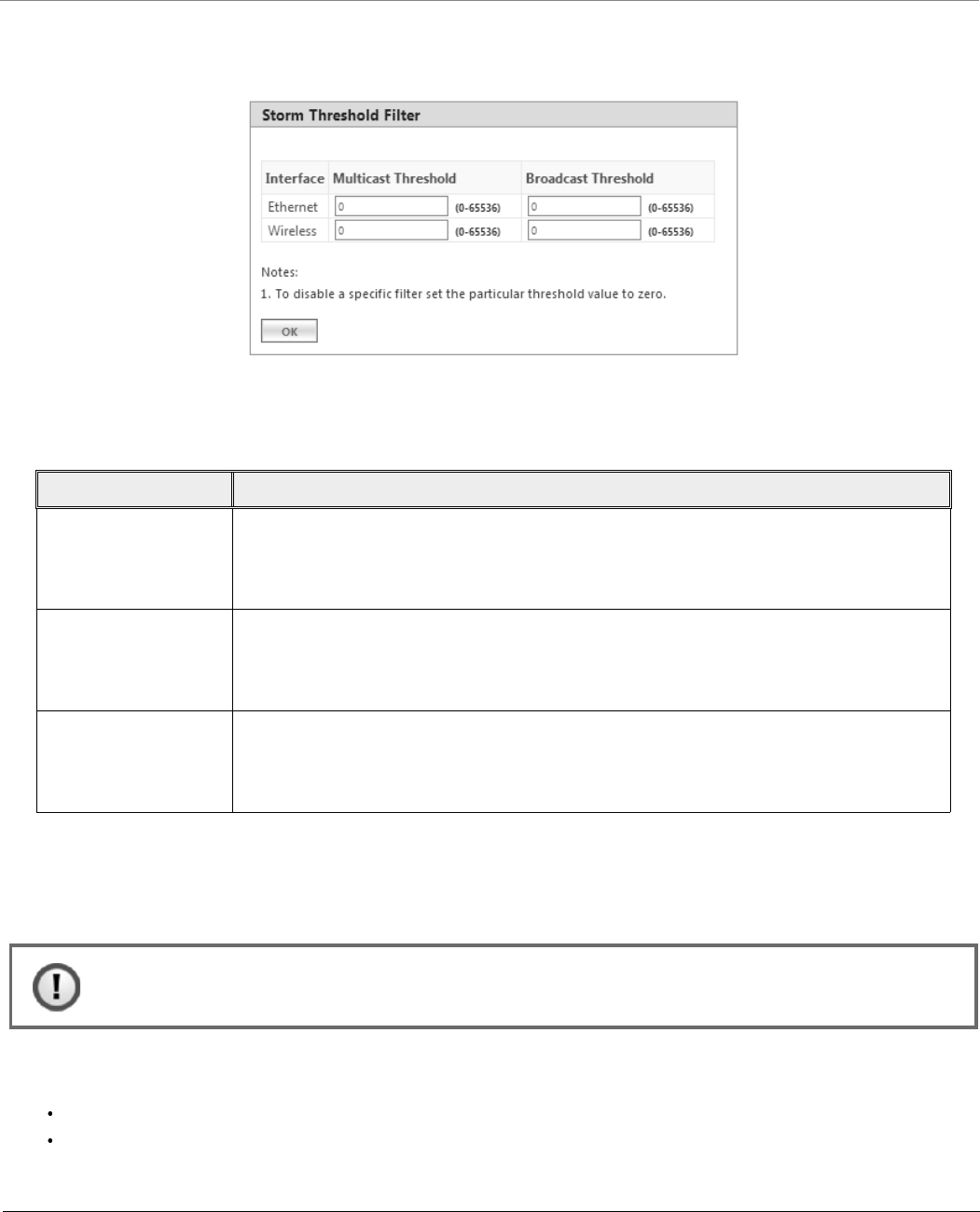
5.10.5 Storm Threshold Filter
The Storm Threshold Filter restricts the excessive inbound multicast or broadcast traffic on layer two interfaces. This protects
against broadcast storms resulting from spanning tree misconfiguration. A broadcast or multicast filtering mechanism needs
to be enabled so that a large percentage of the wireless link remains available to the connected mobile terminals.
Entry Status Set the entry status as either Enable, Disable or Delete.
Enable: Filter is applied and filters the packet based on the Port number and port
type.
Disable: No filter is applied.
Delete: Allows to delete only user-defined TCP/UDP port filter entry. When you
attempt to delete default entries, the device throws an error.
Protocol Name Port Number Port Type Filter Interface Entry Status (Enable/Disable)
NETBIOS Name Service 137 UDP Ethernet Enable
Parameter Description
Advanced Configuration
Tsunami® 800 & 8000 Series - Software Management Guide 180
To configure Storm Threshold Filter, navigate to ADVANCED CONFIGURATION > Filtering > Storm Threshold Filter. The
Storm Threshold Filter screen appears. This screen contains information about the threshold values per second of the
multicast and broadcast packets that can be processed for the interface(s) present in the device.
Figure 5-102 Storm Threshold Filter
Given below is the table which explains Storm Threshold Filter parameters and the method to configure the configurable
parameter(s):
After configuring the required parameters, click OK and then COMMIT.
5.10.6 WORP Intra Cell Blocking
The WORP Intra Cell Blocking feature restricts traffic between SUs which are registered to the same BSU. The two potential
reasons to isolate traffic among the SUs are:
To provide better security by isolating the traffic from one SU to another in a public space.
To block unwanted traffic between SUs to prevent this traffic from using bandwidth.
Parameter Description
Interface Allows to configure the type of interface on which filtering has to be applied. The Storm
Threshold filter can be used to filter the traffic on two types of interfaces: Ethernet or
Wireless. By default, Storm Threshold filtering is disabled on both Ethernet and Wireless
interfaces.
Multicast Threshold Allows to configure the threshold value of the multicast packets to be processed for the
Ethernet or Wireless interface. Packets more than threshold value are dropped. If threshold
value for multicast packets is set to '0', filtering is disabled. The default Multicast
Threshold value is 0 per second.
Broadcast Threshold Allows to configure the threshold value of the broadcast packets to be processed for the
Ethernet or Wireless interface. Packets more than threshold value are dropped. If threshold
value for broadcast packets is set to '0', filtering is disabled. The default Broadcast
Threshold value is 0 per second.
: Intra Cell Blocking is applicable only to a BSU in Bridge Mode only.
Advanced Configuration
Tsunami® 800 & 8000 Series - Software Management Guide 181
The user can form groups of SUs at the BSU which define the filtering criteria. All data to/from SUs belonging to the same
group are bridged. If an SU does not belong to any group, the BSU discards the data.
The user can also configure a Security Gateway to block traffic between SUs connected to different BSUs. All packets destined
for SUs not connected to the same BSU are forwarded to the Security Gateway MAC address (configured under Security
Gateway).
The following rules apply to Intra Cell Blocking Groups:
an SU can be assigned to more than one group.
an SU that has not been assigned to any group cannot communicate to any other SU connected to the same or
different BSU.
5.10.6.0.1 Example of Intra-Cell Blocking Groups
Assume that four Intra Cell Blocking Groups have been configured on a BSU. SUs 1 through 10 are registered to the BSU.
In this example, SU1 belongs to two groups, Group 1 and Group 3. Therefore, packets from SU1 destined to SU4, SU5, SU6
and SU7 are not blocked. However, SU9 belongs to group 4 only and packets from SU9 are blocked unless sent to SU8 or SU
10.
To configuring Intra-Cell Blocking parameters, navigate to ADVANCED CONFIGURATION > Filtering> WORP Intra Cell
Blocking. The following screen appears:
Figure 5-103 Intra Cell Blocking
Group1 Group2 Group3 Group4
SU1 SU2 SU6 SU8
SU4 SU3 SU1 SU9
SU5 SU8 SU7 SU10
Advanced Configuration
Tsunami® 800 & 8000 Series - Software Management Guide 182
This screen is classified into two categories: Intra Cell Blocking and Security Gateway. Given below are the configuration
details.
: Intra Cell Blocking is configurable only in Bridge mode. When you change the device from Bridge to Routing mode
or vice-versa, Intra-Cell Blocking stops or starts working only after device reboot.
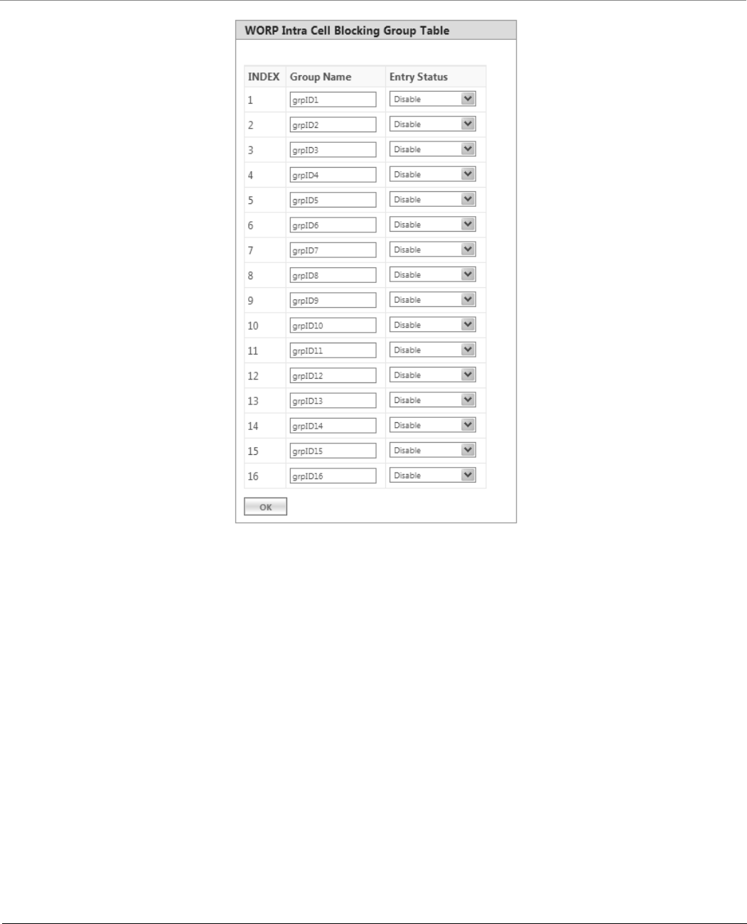
5.10.6.1 WORP Intra Cell Blocking Group Table
The user can form groups of SUs at the BSU which define the filtering criteria. All data to/from SUs belonging to the same
group are bridged. If an SU does not belong to any group, the BSU discards the data.
By default, a BSU supports 16 groups and each group can contain a maximum of 240 SUs. Please note that a single SU can be
a member of all the existing groups.
To view and configure the Intra Cell Blocking Group table, navigate to ADVANCED CONFIGURATION > Filtering> WORP
Intra Cell Blocking > Group Table. The WORP Intra Cell Blocking Group Table screen appears:
Parameter Description
Intra Cell Blocking
Status By default, Intra Cell Blocking is disabled on a BSU. Select Enable to enable the feature
and then Click OK and then COMMIT.
Security Gateway
Status By default, Security Gateway is disabled on a BSU. Select Enable to enable the feature.
MAC Address Represents the MAC address of the security gateway. This gateway routes the packets
transmitted by the SU to the different BSUs to which it belongs.
After configuring the required parameters, click OK and then COMMIT.
Advanced Configuration
Tsunami® 800 & 8000 Series - Software Management Guide 183
Figure 5-104 WORP Intra Cell Blocking Group Table
This table displays the list of groups. If the Entry Status for a group is set to Enable then BSU discards all the packets coming
from SUs which are not members of that group. If set to Disable, then allows all the packets coming from SUs which are not
the members of that group. If you have changed the Entry Status of a group, then click OK and then COMMIT.
5.10.6.2 WORP Intra Cell Blocking MAC Table
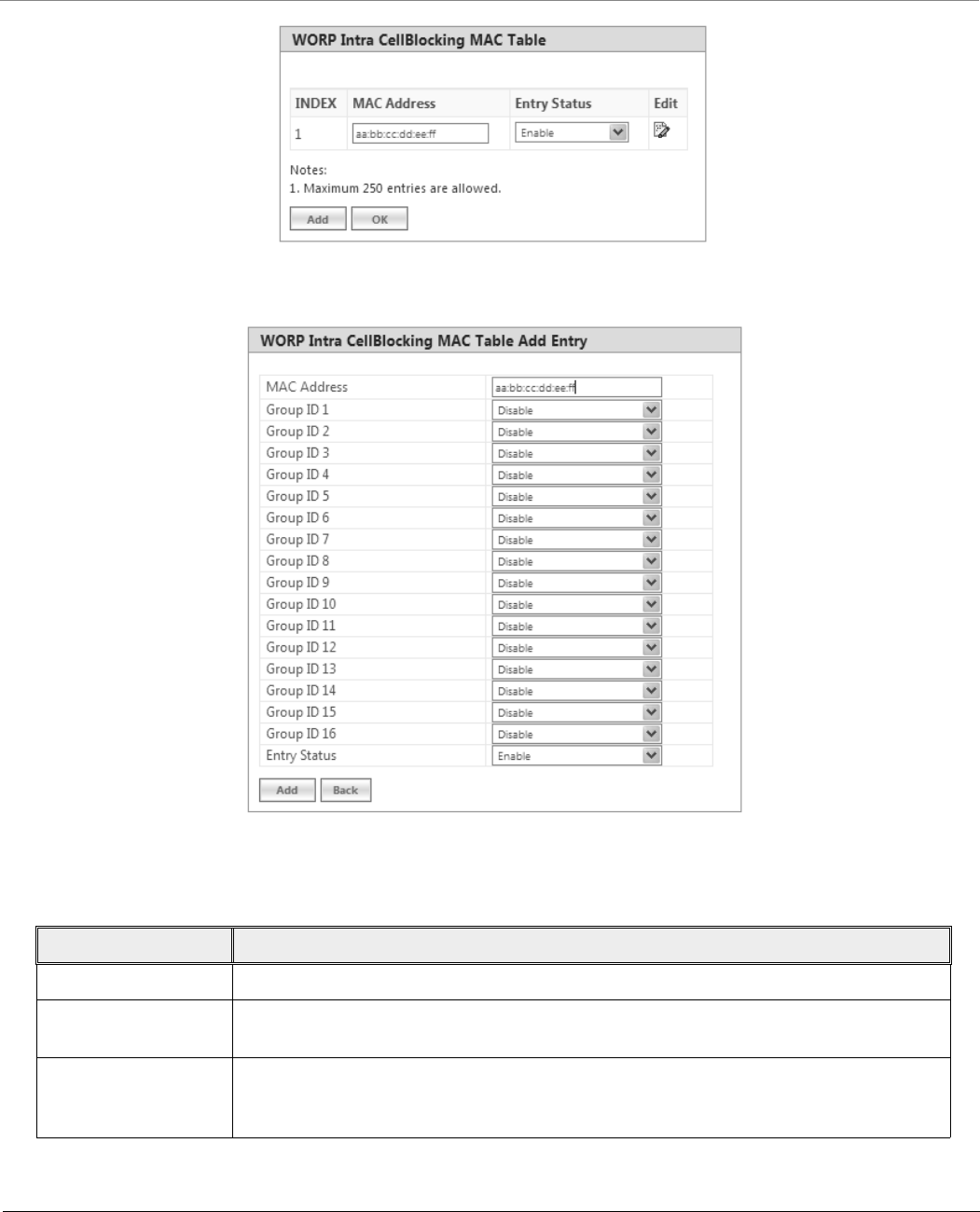
The WORP Intra Cell Blocking MAC table allows to add SU’s MAC address and assign them to the groups. You can add a
maximum of 250 SUs to the table.
To add SU to the table, navigate to ADVANCED CONFIGURATION > Filtering > WORP Intra Cell Blocking > MAC Table.
The WORP Intra Cell Blocking MAC Table screen appears:
Advanced Configuration
Tsunami® 800 & 8000 Series - Software Management Guide 184
Figure 5-105 WORP Intra Cell Blocking MAC Table
5.10.6.2.1 To add MAC addresses, click Add. The following screen appears.
Figure 5-106 WORP Intra Cell Blocking MAC Table Add Entry
Given below is the table which explains the WORP Intra Cell Blocking MAC Table entries and the method to configure the
configurable parameter(s):
After adding the MAC address, click Add.
Parameter Description
MAC Address Represents the MAC address of the SU.
Group ID’s 1 to 16 By default, a Group ID is disabled meaning which the SU is not a part of that group. To
make it a part of that group, select Enable.
Entry Status If SU is part of a group and its Entry Status is enabled then it can communicate with all the
SUs belonging to that group. If Entry Status is disabled, then the communication is
blocked.
Advanced Configuration
Tsunami® 800 & 8000 Series - Software Management Guide 185
To edit the existing MAC addresses, click Edit icon in the WORP Intra Cell Blocking MAC Table screen. Modify the
parameters as desired in the WORP Intra Cell Blocking MAC Table Add Row screen and click OK and then COMMIT.
In the WORP Intra Cell Blocking MAC Table, you can change the Entry Status as either Enable/Disable/Delete. Once the
status is changed, click OK and then COMMIT.
5.11 DHCP
Dynamic Host Configuration Protocol (DHCP) is a network protocol that enables a server to assign an IP address to the DHCP
client from a defined range of IP addresses configured for a given network. Allocating IP addresses from a central location
simplifies the process of configuring IP addresses to individual DHCP clients, and also avoids IP conflicts.
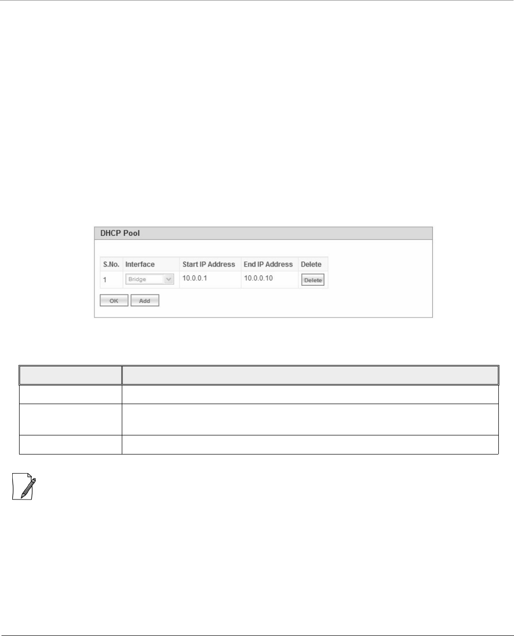
5.11.1 DHCP Pool
DHCP Pool is a pool of defined IP addresses which enables a DHCP Server to dynamically pick IP address from the pool and
assign it to the DHCP client.
To configure a range of IP addresses in the DHCP Pool, navigate to ADVANCED CONFIGURATION > DHCP > DHCP Server
> Pool. The DHCP Pool screen appears:
Figure 5-107 DHCP Pool
Each pool entry comprises the following tabulated information:
: You can add a maximum of five pool entries to the table. A pool entry can be deleted but cannot be edited.
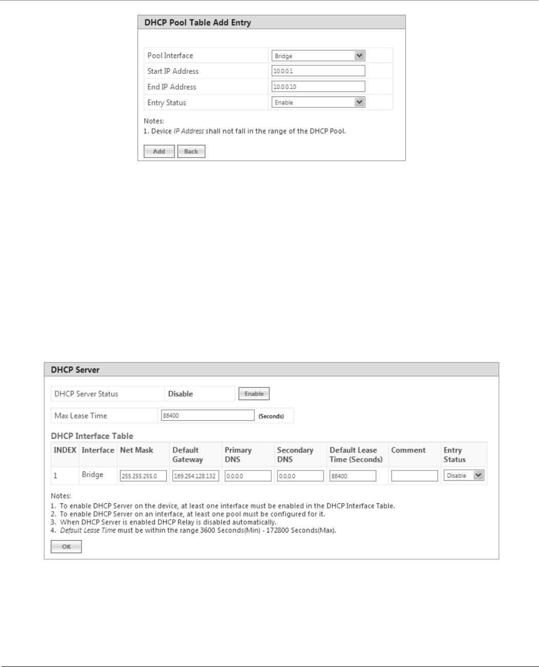
5.11.1.1 Adding a New Pool Entry
To add a new entry to the DHCP Pool, click Add on the DHCP Pool screen. The following DHCP Pool Table Add Row screen
appears:
Parameter Description
Interface Specifies the interface type, that is, Bridge or Routing (Ethernet and Wireless).
Start IP Address and
End IP Address
Specifies the start and end IP address of the addresses to be added to the pool.
Delete Allows you to delete a pool entry.
Advanced Configuration
Tsunami® 800 & 8000 Series - Software Management Guide 186
Figure 5-108 DHCP Pool Table Add Entry
Enter the pool details and click Add. The entry will be updated in the DHCP pool table.
To apply the configured changes, click COMMIT.
5.11.2 DHCP Server
If DHCP Server is enabled, it picks automatically the IP addresses from the specific interface address pool and assigns them to
the respective DHCP clients.
DHCP Server feature is applicable to both Bridge and Routing Mode. In Routing mode, DHCP Server can be configured for
each interface (Ethernet and Wireless) separately. Unless the DHCP Server functionality is enabled for an interface, the DHCP
Server does not respond to the DHCP requests received on that interface.
To configure the DHCP server parameters, navigate to ADVANCED CONFIGURATION > DHCP > DHCP Server > Interface.
The DHCP Server screen appears:
Figure 5-109 DHCP Server (Bridge Mode)
Advanced Configuration
Tsunami® 800 & 8000 Series - Software Management Guide 187
Figure 5-110 DHCP Server (Routing Mode)
Given below is the table which explains DHCP Server parameters and the method to configure the configurable parameter(s):
Parameter Description
DHCP Server Status By default, DHCP Server is disabled on a device. To enable DHCP Server, select Enable.
A DHCP Server can be enabled only when the following two conditions are satisfied:
1. Before enabling, atleast one interface should be enabled on which the DHCP Server
has to run.
2. The DHCP pool table should have atleast one pool configured for that interface.
Max Lease Time Specifies the maximum lease time for which the DHCP client can use the IP address
provided by the DHCP Server. The value ranges from 3600 - 172800 seconds.
DHCP Interface Table
Interface Type Specifies the interface for which the DHCP Server functionality shall be configured.
That is Bridge or Ethernet/Wireless in case of Routing mode.
Net Mask Specifies the subnet mask to be sent to the DHCP client along with the assigned IP
address. The netmask configured here should be greater than or equal to the netmask
configured on the interface.
Default Gateway Specifies the default gateway to be sent to the DHCP client along with the assigned IP
Address. Default Gateway is a node that serves as an accessing point to another network.
Primary DNS Specifies the primary DNS (Domain Name Server) IP address to be sent to the DHCP client.
Secondary DNS Specifies the secondary DNS IP address to be sent to the DHCP client.
Advanced Configuration
Tsunami® 800 & 8000 Series - Software Management Guide 188
After configuring the required parameters, click OK and then COMMIT.
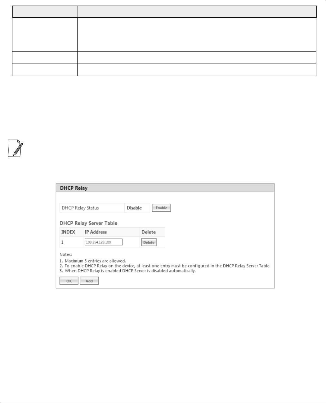
5.11.3 DHCP Relay (Routing Mode only)
The DHCP relay agent relays DHCP messages between the DHCP Clients and the configured DHCP Servers on different IP
networks. You can configure a maximum of five DHCP Servers. There must be at least one DHCP Server configured in order to
relay DHCP request.
: DHCP Relay Agent is configurable only in Routing mode. It cannot be enabled when NAT or DHCP Server is enabled.
To view and configure DHCP Relay Server parameters, navigate to ADVANCED CONFIGURATION > DHCP > DHCP Relay >
Relay Server. The DHCP Relay screen appears:
Figure 5-111 DHCP Relay
By default, DHCP Relay is disabled on the device. To enable it, atleast one DHCP Server IP address should be configured.
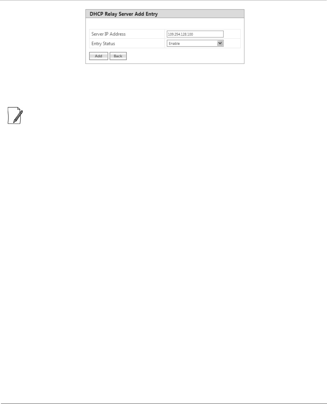
To add a DHCP Server to the Relay Server Table, click Add in the DHCP Relay screen. The DHCP Relay Server Add Row
screen appears:
Default Lease Time DHCP Server uses this option to specify the lease time it is willing to offer to the DHCP
client over that interface. Once the lease time expires, the DHCP Server allocates a new IP
address to the device. The Default Lease Time should be less than or equal to the
configured Max Lease Time.
Comment Specifies a note for the device administrator.
Entry Status Used to Enable or Disable the DHCP Server functionality over the interface.
Parameter Description
Advanced Configuration
Tsunami® 800 & 8000 Series - Software Management Guide 189
Figure 5-112 DHCP Relay Server Add Entry
Enter the DHCP Server IP Address and then click Add.
After configuring the required parameters, click OK and then COMMIT.
: DHCP server is disabled automatically if DHCP Relay agent is enabled and vice-verse.
Advanced Configuration
Tsunami® 800 & 8000 Series - Software Management Guide 190
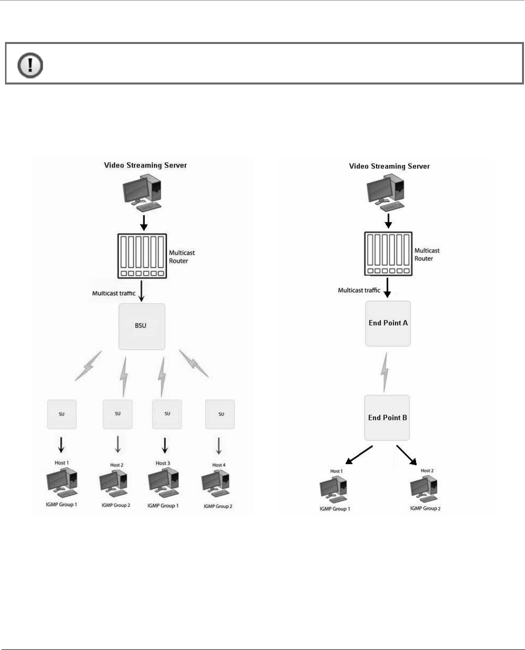
5.12 IGMP Snooping
Proxim’s Tsunami® devices support Internet Group Management Protocol (IGMP) Snooping feature. With IGMP Snooping
enabled on the device, multicast traffic is only forwarded to ports that are members of the specific multicast group. By
forwarding the traffic only to the destined ports, reduces unnecessary load on devices to process packets.
Explained below is the IGMP Snooping process with the help of a diagram:
Figure 5-113 IGMP Snooping Process
The router forwards the IP multicast data to the BSU/End Point A.
Lets say, with IGMP Snooping not enabled on the BSU/End Point A, the multicast data is transmitted over the wireless medium
irrespective of whether the multicast group address is a member of the multicast group table maintained in each BSU/End
Point A. With IGMP Snooping enabled, the BSU/End Point A transmits the data only when the multicast group address is a
member of the multicast group table, else drops the packet. The SU/End Point B will receive the multicast data.
: IGMP Snooping is applicable only in Bridge Mode.
Advanced Configuration
Tsunami® 800 & 8000 Series - Software Management Guide 191
Similarly, with IGMP Snooping not enabled on the SU/End Point B, the multicast data is transmitted irrespective of whether
the multicast group address is a member of the multicast group table maintained in each SU/End Point B. With IGMP
Snooping enabled, the SU/End Point B transmits the data to the host only when the multicast group address is a member of
the multicast group table, else drops the packet.
IGMP Snooping is of 2 kinds:
Active: Active IGMP Snooping listens to IGMP traffic and filters IGMP packets to reduce load on the multicast router.
Passive: Passive IGMP Snooping simply listens to IGMP traffic and does not filter or interfere with IGMP.
:
Tsunami® devices supports only passive IGMP Snooping.
IGMP versions v1,v2 and v3 are supported.
The device can add a maximum of 64 Multicast groups in the Snooping table.
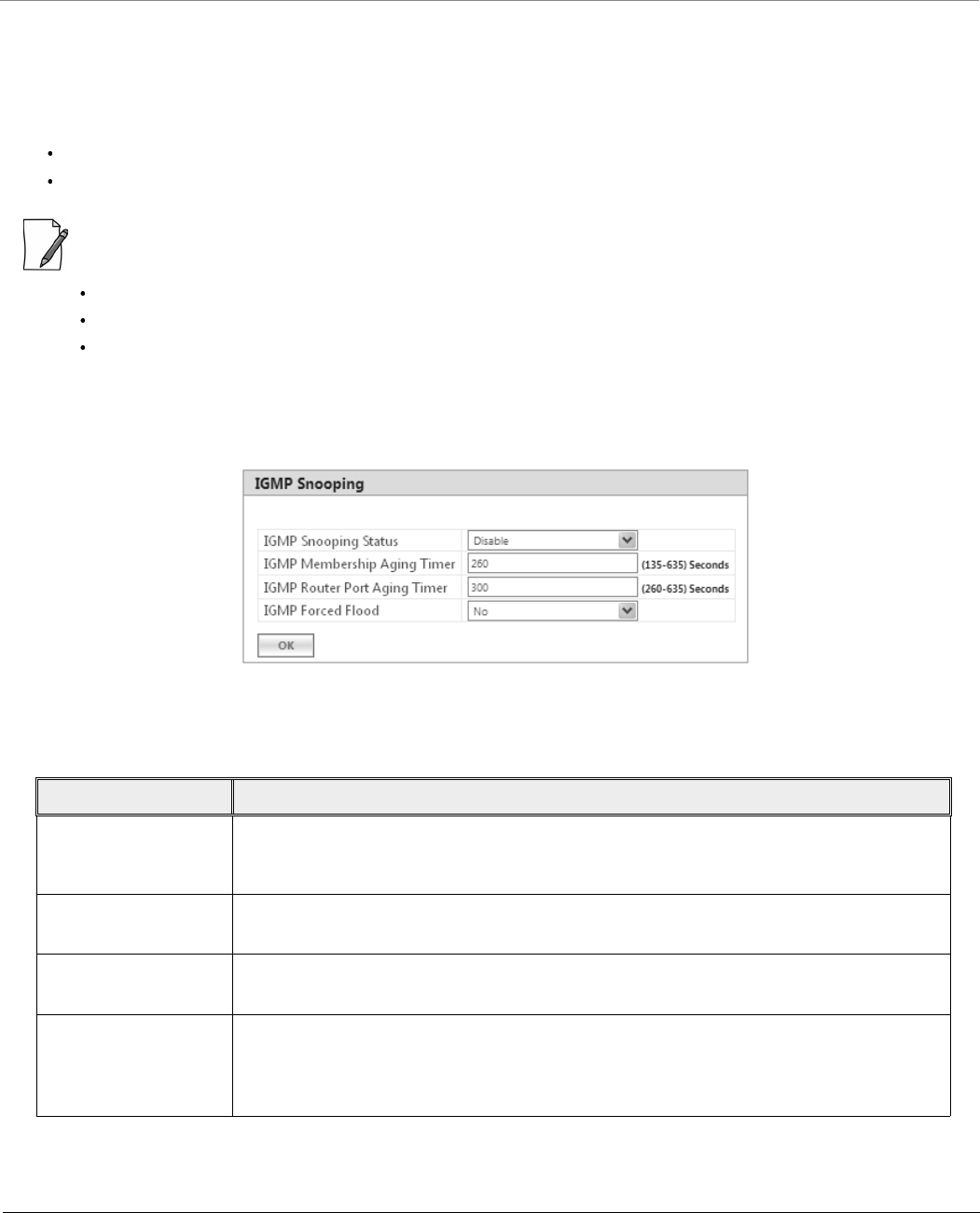
To configure IGMP Snooping parameters, navigate to ADVANCED CONFIGURATION > IGMP Snooping. The following
IGMP Snooping screen appears:
Figure 5-114 IGMP Snooping
Given below is the table which explains IGMP Snooping parameters and the method to configure the configurable
parameter(s):
After configuring the required parameters, click OK and then COMMIT.
Parameter Description
IGMP Snooping Status By default, IGMP Snooping Status is disabled on the device, meaning which, the device
transmits IP multicast traffic to all the ports. To forward the traffic only to the members of
the specific multicast group, enable IGMP Snooping Status.
IGMP Membership
Aging Timer
Represents the time after which the IGMP multicast group age-outs or elapses. It ranges
from 135 to 635 seconds. The default Aging Timer is 260 seconds.
IGMP Router Port
Aging Timer
Represents the time after which the IGMP Router port age-outs or elapses. It ranges from
260 to 635 seconds. The default Aging Timer is 300 seconds.
IGMP Forced Flood If you select Yes, all the unregistered IPv4 multicast traffic (with destination address which
does not match any of the groups announced in earlier IGMP Membership reports) and
IGMP Membership Reports will be flooded to all the ports. By default, IGMP Forced Flood
is set to No.
Tsunami® 800 & 8000 Series - Software Management Guide 192
Management
This chapter provides information on how to manage the device by using Web interface. It contains information on the
following:
6.1 System
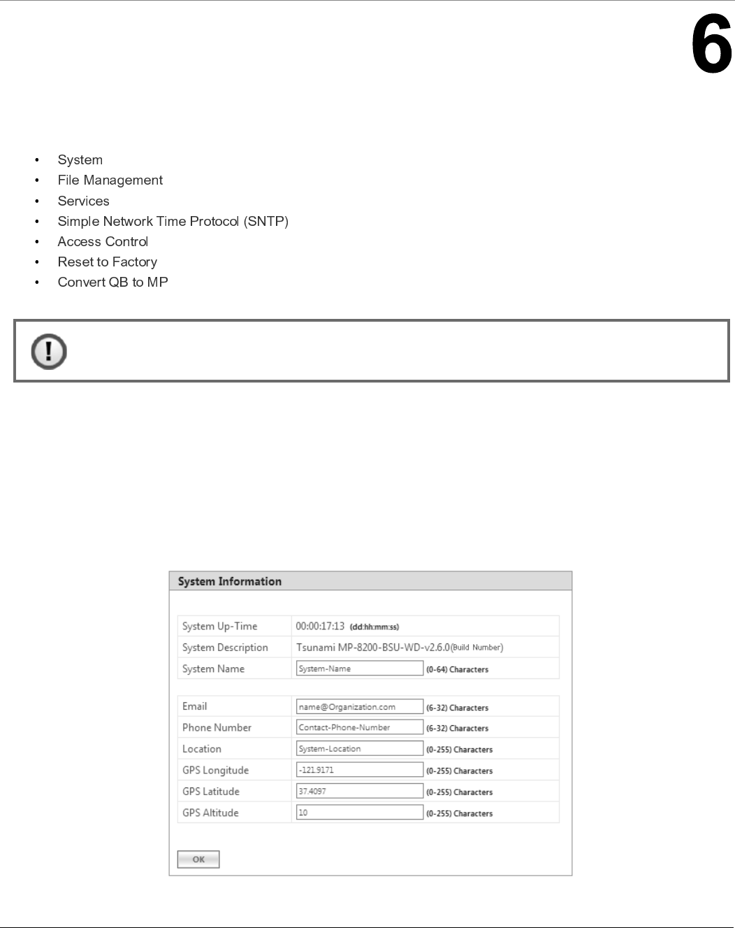
6.1.1 System Information
The System Information tab enables you to view and configure system specific information such as System Name, System
Description, Contact Details of the person managing the device, and so on.
To view and configure system specific Information, navigate to MANAGEMENT > System > Information. The System
Information screen appears:
Figure 6-1 System Information
: Recommended characters for the name field are A-Z a-z 0-9 - _ = : . @ $ & and space.

Management
Tsunami® 800 & 8000 Series - Software Management Guide 193
Given below is the table which explains System parameters and the method to configure the configurable parameter(s):
After configuring the required parameters, click OK and then COMMIT.
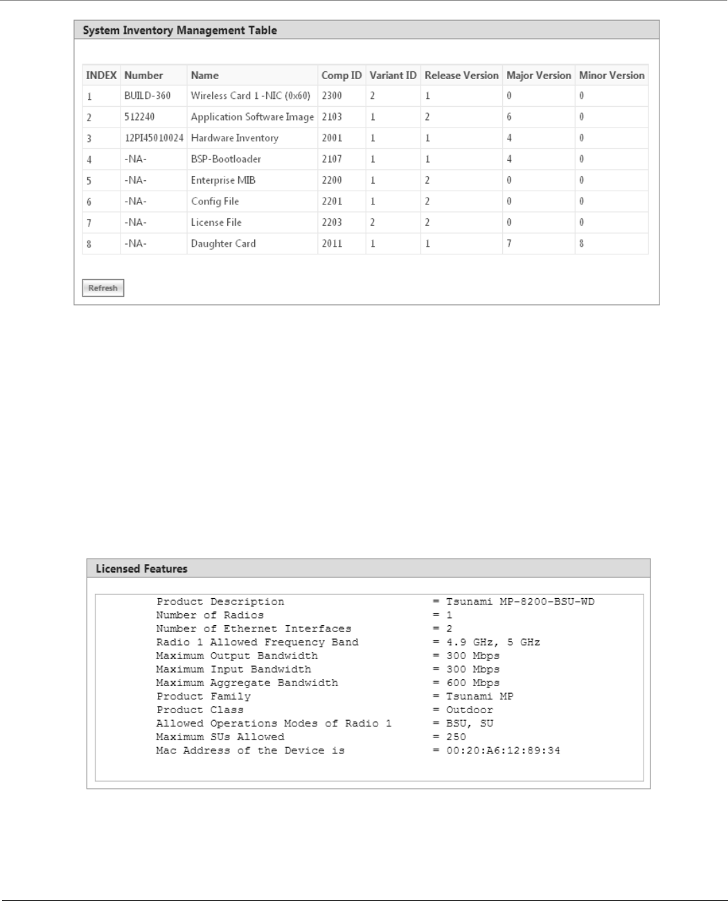
6.1.2 Inventory Management
The Inventory Management tab provides inventory information about the device.
To view inventory information, navigate to MANAGEMENT > System > Inventory Management. The System Inventory
Management Table appears.
Parameter Description
System Up-Time This is a read-only parameter. It represents the operational time of the device since its last
reboot.
System Description This is a read-only parameter. It provides system description such as system name,
firmware version and the latest firmware build supported.
For example: MP-8100-BSU-WD-v2.X.Y(Build No.)
System Name Represents the name assigned to the device. You can enter a system name of maximum 64
characters and should be unique across all devices in WORP network.
Email Represents the email address of the person administering the device. You can enter an
email address of minimum 6 and maximum 32 characters.
Phone Number Represents the phone number of the person administering the device. You can enter a
phone number of minimum 6 and maximum 32 characters.
Location Represents the location where the device is installed. You can enter the location name of
minimum 0 and maximum 255 characters.
GPS Longitude Represents the longitude at which the device is installed. You can enter a longitude value
of minimum 0 and maximum 255 characters.
GPS Latitude Represents the latitude at which the device is installed. You can enter a latitude value of
minimum 0 and maximum 255 characters.
GPS Altitude Represents the altitude at which the device is installed. You can enter a altitude value of
minimum 0 and maximum 255 characters.
Management
Tsunami® 800 & 8000 Series - Software Management Guide 194
Figure 6-2 An Example - Inventory Management
By default, the components information is auto-generated by the device and is used only for reference purpose.
Click Refresh, to view the updated system inventory management information.
6.1.3 Licensed Features
Licensing is considered to be the most important component of an enterprise-class device which typically has a feature-based
pricing model. It is also required to prevent the misuse and tampering of the device by a wide-variety of audience whose
motives may be intentional or accidental.
Licensed Features are, by default, set by the company.
To view the licensed features set on the device, click MANAGEMENT > System > Licensed Features. The Licensed
Features screen appears.
Figure 6-3 Licensed Features

Management
Tsunami® 800 & 8000 Series - Software Management Guide 195
Given below is the table which explains each of the parameters:
6.1.3.1 License Upgrade Procedure
In order to get additional bandwidth, Upgrade the License by following the procedure given below:
Retrieve the license information (License Info file with .lic extension) from the device. For more details, refer
section.
To purchase a license upgrade, please contact your Proxim Sales Representative; to generate a unique license file for
your device, please refer to the Technical Note available on Proxim support site:
Upgrade the bandwidth using the license file(.bin extension) generated in the above step. For more details, refer
section.
6.2 File Management
The File Management tab enables you to upgrade the firmware and configuration files onto the device, and retrieve
configuration and log files from the device through Hypertext Transfer Protocol (HTTP) and Trivial File Transfer Protocol (TFTP).
Parameter Description
Product Description Description about the device.
Number of Radios The number of radios the device supports.
Number of Ethernet
Interfaces
The number of Ethernet interfaces supported by the device.
Radio 1 Allowed
Frequency Band
The operational frequency band supported by the device radio.
Maximum Output
Bandwidth
The maximum output bandwidth limit of the device. It is represented in mbps.
Maximum Input
Bandwidth
The maximum input bandwidth limit of the device. It is represented in mbps.
: The Input and Output Bandwidth features are referred with respect to the
wireless interface. Input bandwidth refers to the data received on the wireless
interface and output bandwidth refers to the data sent out of the wireless
interface.
Maximum Aggregate
Bandwidth
The maximum cumulative bandwidth of the device, which is the sum of configured output
and input bandwidths.
Product Family Represents the product family of the device.
Product Class Represents the product class of the device, which is either indoor or outdoor.
Allowed Operational
Modes of Radio1
Represents the operational mode of the device, that is, BSU/SU/End Point A/End Point B.
Maximum SUs
Allowed
The maximum number of SUs that a BSU supports.
MAC address of the
Device is
The MAC address of the device.
Management
Tsunami® 800 & 8000 Series - Software Management Guide 196
6.2.1 TFTP Server
A Trivial File Transfer Protocol (TFTP) server lets you transfer files across a network. By using TFTP, you can retrieve files from
the device for backup or copying, and you can upgrade the firmware or the configuration files onto the device. You can
download the SolarWinds TFTP server application from . You can also download the latest TFTP
software from SolarWinds Web site at .
While using TFTP server, ensure the following:
The upload or download directory is correctly set (the default directory is C:\TFTP-Root).
The required firmware file is present in the directory.
The TFTP server is running during file upload and download. You can check the connectivity between the device and
the TFTP server by pinging the device from the Personal Computer that hosts the TFTP server. The ping program
should show replies from the device.
The TFTP server should be configured to transmit and receive files (on the Security tab under File > Configure), with
no automatic shutdown or time-out (on the Auto-Close tab).
: The instructions listed above are based on the assumption that you are using the SolarWinds TFTP server; otherwise
the configuration may vary.
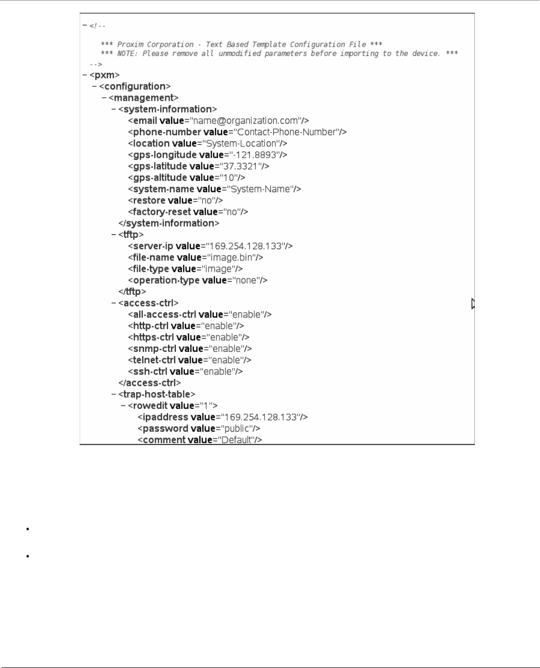
6.2.2 Text Based Configuration (TBC) File Management
Text Based Configuration (TBC) file is a simple text file that holds device template configurations. The device supports the TBC
file in XML format which can be edited in any XML or text editors.
You can generate the TBC file from the CLI Session and manually edit the configurations and then load the edited TBC file to
the device so that the edited configurations are applied onto the device. It differs mainly from the binary configuration file in
terms of manual edition of configurations. The generated TBC file is a template which has only the default and modified
configurations on the live CLI session.
6.2.2.1 Generating TBC File
The TBC file is generated through CLI by executing generate command.
While generating the TBC file from CLI, there is an option to generate it with or without all Management and Security
Passwords. The management passwords include CLI/WEB/SNMP passwords. The security passwords include
Network-Secret/Encryption-Key(s)/RADIUS-Shared-Secret. If included, these passwords become a part of the generated TBC
file and are in a readable form. If excluded, all these passwords are not part of the generated TBC file.
The commands used for the generation of TBC file are:
The generated TBC file contains,
Default configurations
Any user-added or edited configurations on current live CLI session
The generated Text Based Template Configuration file appears as shown below:
Management
Tsunami® 800 & 8000 Series - Software Management Guide 197
Figure 6-4 TBC File in xml Format
6.2.2.2 Editing the TBC File
The TBC file can easily be opened and edited in any standard Text-Editors like Wordpad, MS-Word, Notepad++, Standard
XML Editors. Proxim recommends XML Notepad 7 editor for editing the TBC file.
You can modify any value between the double quotes(““) in the TBC file. It is recommended not to change the text
outside the double quotes (“”) or XML tags in the TBC file.
Remove unchanged configurations from the TBC file before loading onto the device.
Management
Tsunami® 800 & 8000 Series - Software Management Guide 198
6.2.2.3 Loading the TBC file
The TBC file can be loaded onto the device by using either SNMP, Web Interface or CLI. You can either use TFTP or HTTP to
load the TBC file.
By using Web Interface, you can load the TBC file by navigating to MANAGEMENT > File Management > Upgrade
Configuration. To load the TBC file, it should be generated or downloaded onto the device. While loading the TBC file onto
the device, any file name is accepted. Once loaded, the TBC file name is renamed to PXM-TBC.xml.
If the TBC file does not contain correct XML syntax, the file will be discarded with DOM error and no configurations will be
loaded. All duplicate values entered are considered as errors while loading and syslogs will be generated accordingly.
Therefore, it is recommended to delete all unchanged parameters from the TBC file during its edition. Commit is required to
retain the configurations across reboots after loading the TBC file.
: Both Commit and Reboot are required to accept the modifications done in the TBC File. Only reboot is required to
reject the modifications.
Loading the TBC file is allowed only once in an active device session (that is, if TBC file is loaded, reboot is required to apply all
configurations or to load another TBC file). All configurations in the TBC file are loaded to the device irrespective of their
default or modified or added configurations. Loading the TBC file takes approximately 10-20 seconds depending on the
number of configurations added.
:
Remove any unmodified parameters from the TBC file, before loading it.
If you get any timeout errors while loading TBC file from SNMP interface, increase the time-out value to more than
30 seconds in the MIB Browser.
6.2.3 Upgrade Firmware
You can update the device with the latest firmware either through HTTP or TFTP.
:
Make sure the firmware being loaded is compatible to the device being upgraded.
In a point-to-multipoint network, it is recommended to upgrade the base station first and then the subscriber(s).
In a point-to-point network, it is recommended to upgrade the End Point A first and then the End Point B.
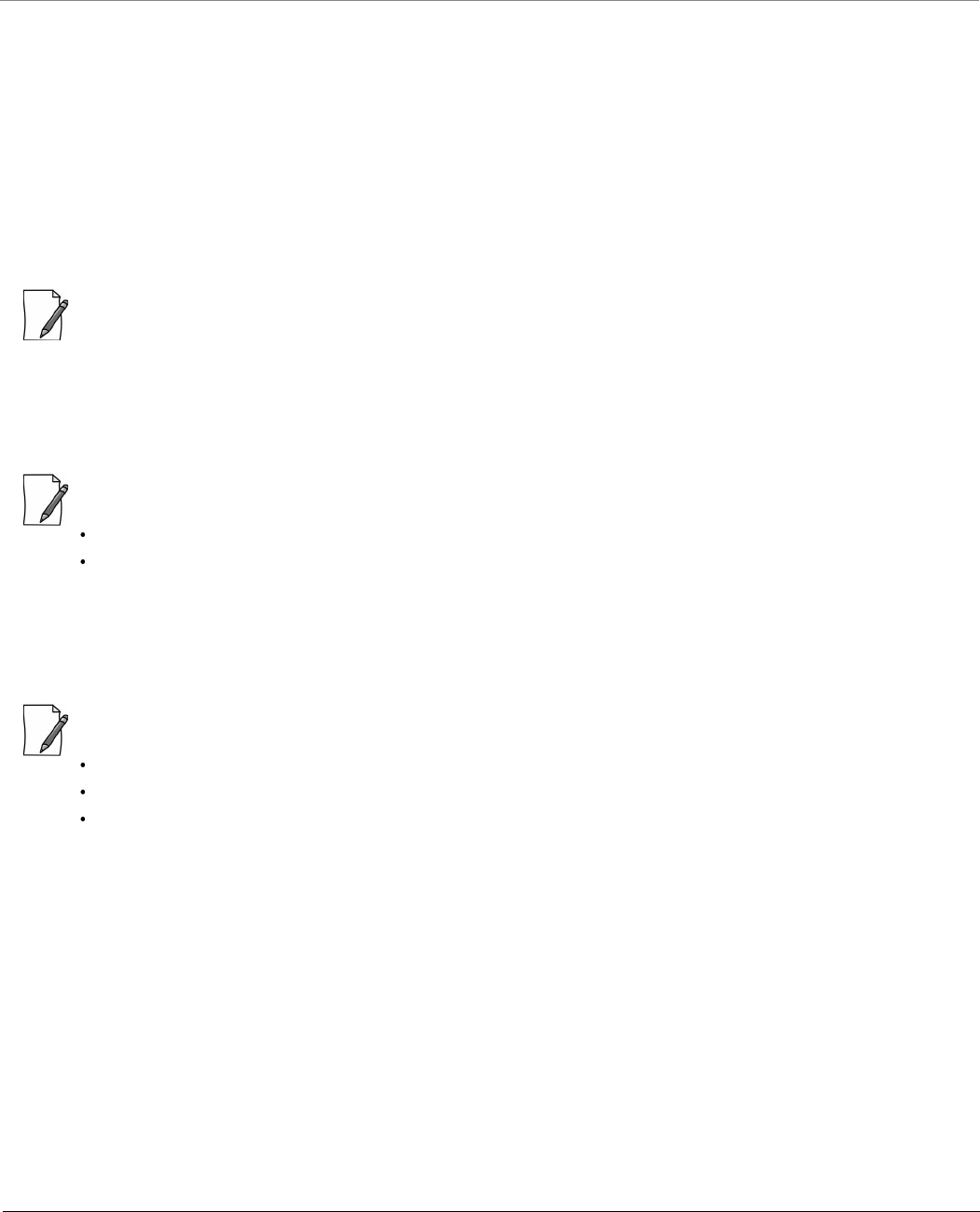
6.2.3.1 Upgrade Firmware via HTTP
To upgrade the firmware via HTTP, do the following:
1. Navigate to MANAGEMENT > File Management > Upgrade Firmware > HTTP.
Management
Tsunami® 800 & 8000 Series - Software Management Guide 199
Figure 6-5 Upgrade Firmware - HTTP
2. In the HTTP screen, click Browse to select the latest firmware file from the desired location. Ensure that the file name
does not contain any space or special characters.
3. Click Upgrade.
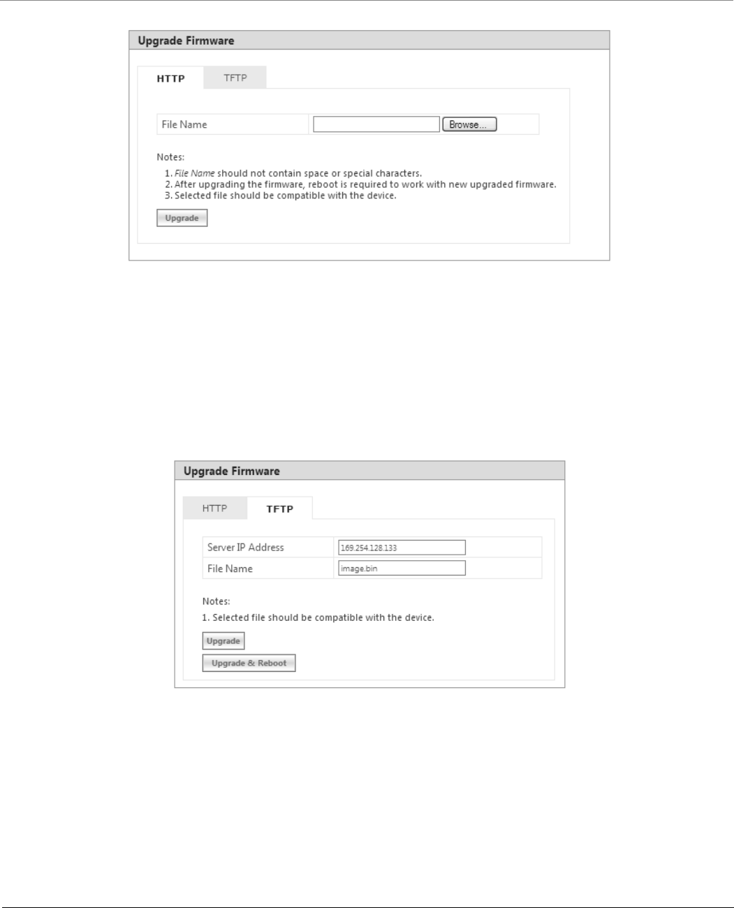
6.2.3.2 Upgrade Firmware via TFTP
To upgrade the firmware via TFTP Server, do the following:
1. Navigate to MANAGEMENT > File Management > Upgrade Firmware > TFTP.
Figure 6-6 Upgrade Firmware - TFTP
2. Based on the IP mode configure either IPv4 or IPv6 address as TFTP Server address.
3. Enter the name of the latest firmware file (including the file extension) that has to be loaded onto the device in the
File Name box.
4. To upgrade the device with new firmware click Upgrade and then reboot the device, or click Upgrade & Reboot.
Management
Tsunami® 800 & 8000 Series - Software Management Guide 200
:
After upgrading the device with the new firmware, reboot the device; Otherwise the device will continue to run
with the old firmware.
It is recommended not to navigate away from the upgrade screen, while the upgrade is in progress.
6.2.4 Upgrade Configuration
You can upgrade the device with the latest configuration files either through HTTP or TFTP.
: Make sure the configuration file being loaded into the device is compatible. That is, the configuration file being
loaded should have been retrieved from a device of the same SKU.
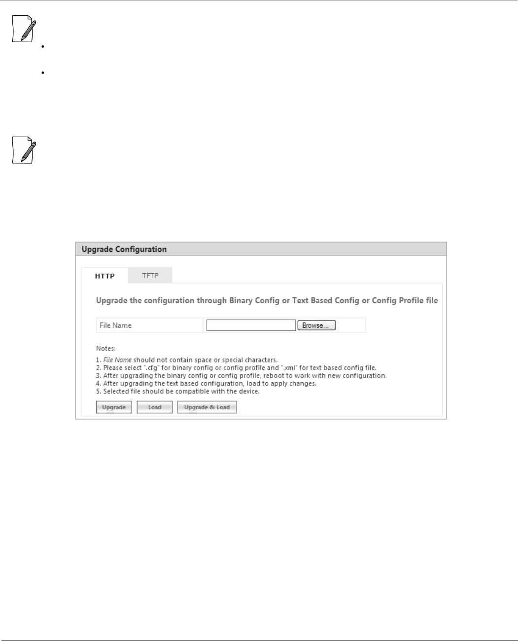
6.2.4.1 Upgrade Configuration via HTTP
To upgrade the configuration files by using HTTP, do the following:
1. Navigate to MANAGEMENT > File Management > Upgrade Configuration > HTTP.
Figure 6-7 Upgrade Configuration - HTTP
2. In the HTTP screen, click Browse to locate the configuration file. Select a Binary Configuration file or a Config Profile
file, or a PXM-TBC.xml for Text Based Configuration file. Make sure that the file name does not contain any space or
special characters.
3. If you are upgrading the device with Binary Configuration file then click Upgrade and then reboot the device.
4. If you are upgrading the device with Config Profile file then click Upgrade and then reboot the device. On upgrade,
the device shall come up with the loaded profile. If the configuration profile is not compatible, then on reboot, the
device will rollback to its old configuration.
5. If you are upgrading the device with Text Based Configuration file then click Upgrade to upgrade the device with the
config file and then click Load for loading the config file onto the device. Alternatively, you can perform both upgrade
and load operation in one single step, by clicking Upgrade & Load.
Management
Tsunami® 800 & 8000 Series - Software Management Guide 201
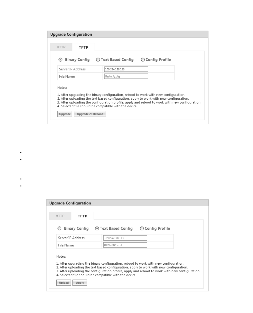
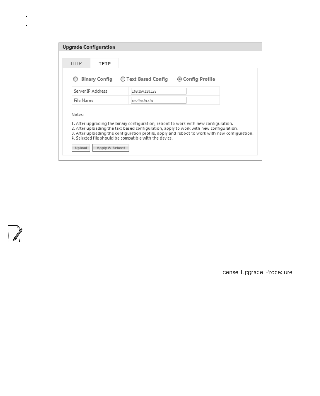
6.2.4.2 Upgrade Configuration via TFTP
To upgrade the configuration files by using TFTP Server, do the following:
1. Navigate to MANAGEMENT > File Management > Update Configuration > TFTP.
Figure 6-8 Upgrade Binary Configuration via TFTP
2. You can update the device with three types of configuration files: Binary, Text Based and Config Profile. To update the
device with Binary Configuration file, select Binary Config.
Based on the IP mode configure either IPv4 or IPv6 address as TFTP Server address.
Enter the name of the Binary file (including the file extension) that has to be downloaded onto the device in the
File Name box.
3. To update the device with Text Based Configuration files, select Text Based Config.
Based on the IP mode configure either IPv4 or IPv6 address as TFTP Server address.
Enter the name of the Text Based file (including the file extension) that has to be downloaded onto the device in
the File Name box.
Figure 6-9 Upgrade Text Based Configuration via TFTP
Management
Tsunami® 800 & 8000 Series - Software Management Guide 202
4. To update the device with Configuration Profile files, select Config Profile.
Based on the IP mode, configure either IPv4 or IPv6 address as TFTP Server address.
Enter the name of the Config Profile file (including the file extension) that has to be downloaded onto the device
in the File Name box.
Figure 6-10 Upgrade Configuration Profile via TFTP
5. If you are upgrading the device with Binary Configuration file then click Upgrade and then reboot the device, or click
Upgrade & Reboot.
6. If you are upgrading the device with Text Based Configuration file, click Upload and then click Apply.
7. If you are upgrading the device with Config profile file then click Upload and then reboot the device, or click Apply
& Reboot.
: It is recommended not to navigate away from the upgrade screen, while the upgrade is in progress.
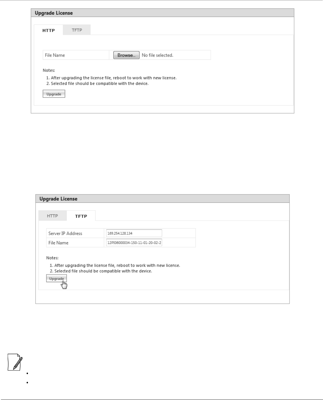
6.2.5 Upgrade License
You can upgrade the license file on the device either through HTTP or TFTP. Refer section for
more details.
6.2.5.1 Upgrade License via HTTP
To upgrade the license using HTTP, do the following:
1. Navigate to MANAGEMENT > File Management > Upgrade License > HTTP.
Management
Tsunami® 800 & 8000 Series - Software Management Guide 203
Figure 6-11 Upgrade License via HTTP
2. In the HTTP screen, click Browse to locate the license upgrade(.bin) file to be loaded on the device.
3. Click Upgrade button to upgrade the license on the device and then reboot the device.
6.2.5.2 Upgrade License via TFTP
To upgrade the license file using TFTP Server, do the following:
1. Navigate to MANAGEMENT > File Management > Update License > TFTP.
Figure 6-12 Upgrade License via TFTP
2. Based on the IP mode, configure either IPv4 or IPv6 address as TFTP Server address.
3. Enter the name of the file (including the file extension) that has to be loaded on the device, in the File Name box.
4. Click Upgrade button to upgrade the license on the device and then reboot the device.
:
Upgrade license can be done through CLI/Web Interface/SNMP.
It is applicable only to MP-820-BSU-100, MP-820-SUA-50+, MP-825-SUR-50+, and QB-825-LNK-50+ devices.
Management
Tsunami® 800 & 8000 Series - Software Management Guide 204
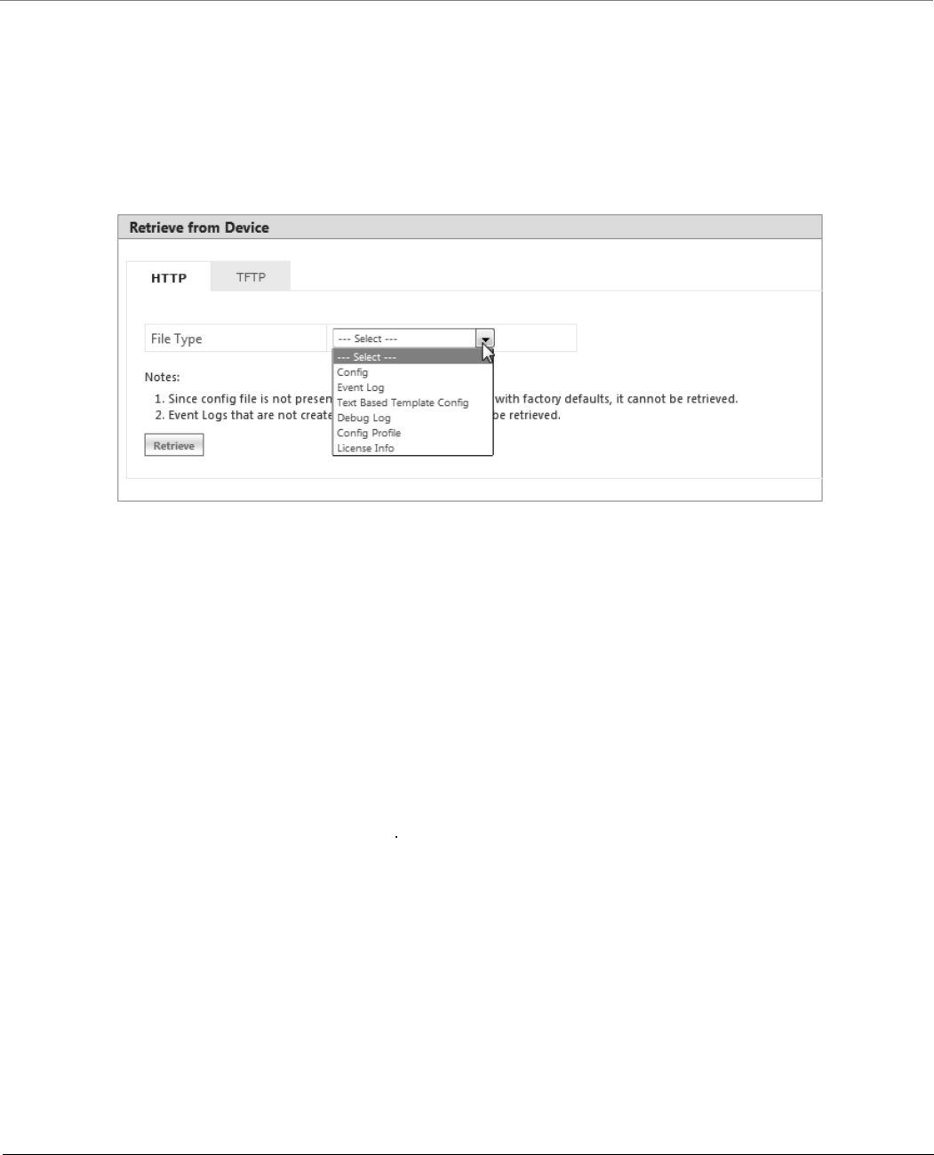
6.2.6 Retrieve From Device
The Retrieve From Device tab allows you to retrieve logs, config files, and license info from the device either through HTTP
or TFTP.
6.2.6.1 Retrieve from Device via HTTP
To retrieve files from the device by using HTTP, do the following:
1. Navigate to MANAGEMENT > File Management > Retrieve from Device > HTTP.
Figure 6-13 Retrieve Files via HTTP
2. Select the type of file that you want to retrieve from the device from the File Type drop down box. The files may vary
depending on your device. The File Types are:
a. Config
b. Event Log
c. Temperature Log
d. Text Based Template Config
e. Debug Log
f. Config Profile
g. License Info
The Config Profile is used for replicating the configuration of a master device on to other similar devices by
excluding the unique parameters like System information, IP configuration, Ethernet configuration, Wireless
configuration based on the selection By default, System Information and IP Configuration parameters are
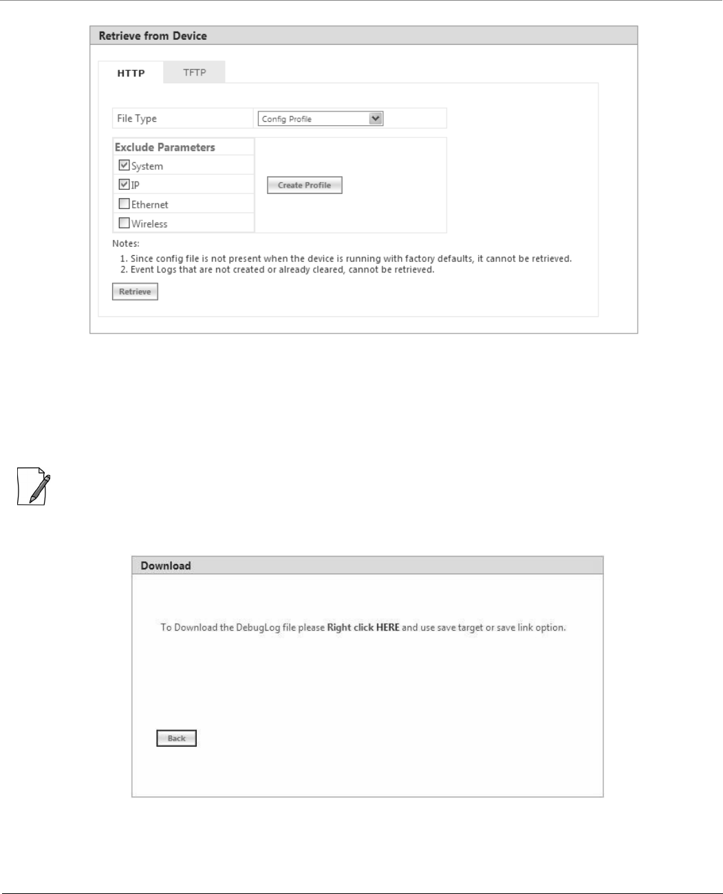
excluded. On selecting config profile type the following screen appears:
Management
Tsunami® 800 & 8000 Series - Software Management Guide 205
Figure 6-14 Retrieve Config Profile File via HTTP
After excluding the unique parameters, click Create Profile for creating the profile and then click Retrieve.
When the retrieved configuration profile file is loaded on target devices, the target devices will come up with
configuration of the master device except the excluded parameters. The excluded parameters are retained as
configured on the target device.
: Config Profile is applicable only to the compatible devices.
3. Click Retrieve. Based on the selected file, the following Download screen appears.
Figure 6-15 Download Screen
4. Right-click the Download link and select Save Target As or Save Link As to save the file to the desired location.
Management
Tsunami® 800 & 8000 Series - Software Management Guide 206
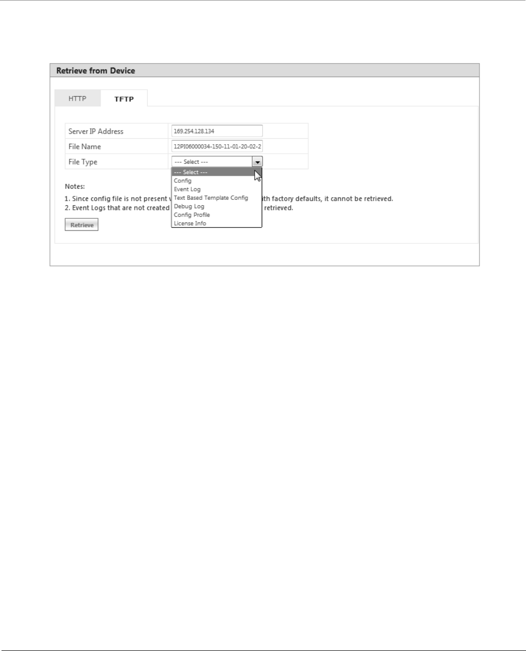
6.2.6.2 TFTP Retrieve
To retrieve files from the device by using TFTP, do the following:
1. Navigate to MANAGEMENT > File Management > Retrieve from Device > TFTP.
Figure 6-16 Retrieve Files via TFTP
2. Based on the IP mode, configure either IPv4 or IPv6 address as TFTP Server address.
3. Enter the name of the file (including the file extension) that has to be retrieved from the device, in the File Name box.
4. Select the file type that you want to retrieve from the device, from the File Type drop down box. The file types are:
a. Config
b. Event Log
c. Temperature Log
d. Text Based Template Config
e. Debug Log
f. Config Profile
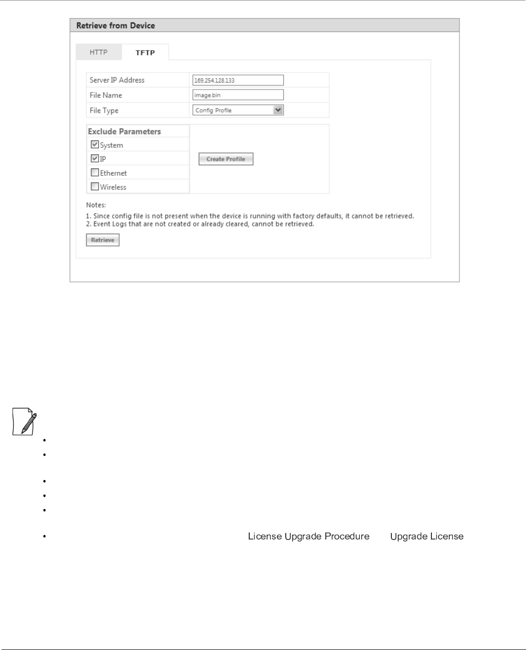
g. License Info
The Config Profile is used for replicating the configuration of a master device on to other similar devices by
excluding the unique parameters like System information, IP configuration, Ethernet configuration, Wireless
configuration based on the selection. By default, System Information and IP Configuration parameters are
excluded. On selecting config profile type the following screen appears:
Management
Tsunami® 800 & 8000 Series - Software Management Guide 207
Figure 6-17 Retrieve Config Profile File via TFTP
After excluding the unique parameters, click Create Profile for creating the profile and then click Retrieve.
When the retrieved configuration profile file is loaded on the target devices, the target devices will come up with
configuration of the master device except the excluded parameters. The excluded parameters are retained as
configured on the target device.
5. Click Retrieve. The retrieved file can be found in the TFTP Server folder.
Config Profile is applicable only to the compatible devices.
When the device is running with default factory settings, there is no Binary Configuration file present and hence it
cannot be retrieved.
Similarly, the Text Based Template Configuration file does not exist if it is not generated from the CLI.
You can retrieve Event Logs only when they are generated by the device.
Retrieval of license info file (CLI/Web Interface/SNMP) is supported only by MP-820-BSU-100, MP-820-SUA-50+,
MP-825-SUR-50+, and QB-825-LNK-50+ devices.
For more information on license upgrade, refer and sections.
6.3 Services
The Services tab lets you configure the HTTP/HTTPS, Telnet/SSH and SNMP interface parameters.
6.3.1 HTTP/HTTPS
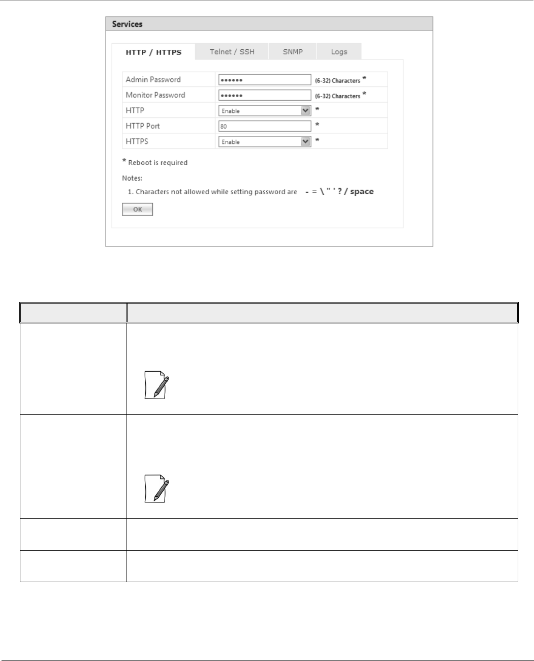
To configure HTTP/HTTPS interface parameters, navigate to MANAGEMENT > Services > HTTP / HTTPS.
Management
Tsunami® 800 & 8000 Series - Software Management Guide 208
Figure 6-18 HTTP/HTTPS
Given below is the table which explains HTTP/HTTPS parameters and the method to configure the configurable parameter(s).
Parameter Description
Admin Password By default, the Administrator password to access HTTP/HTTPS interface is public. For
security reasons, it is recommended to change the default password. The password should
be alphanumeric with minimum of 6 and maximum of 32 characters.
: The following special characters are not allowed in the password:
- = \ “ ‘ ? / space
Monitor Password The Administrator user has the privilege to change the Monitor user password. By default,
the Monitor user password to access HTTP/HTTPS interface is public. For security reasons it
is recommended to change the default password. The password should be alphanumeric
with minimum of 6 and maximum of 32 characters.
: The following special characters are not allowed in the password:
- = \ “ ‘ ? / space
HTTP By default, a user can manage the device through Web Interface. To prevent access to the
device through Web Interface, select Disable.
HTTP Port Represents the HTTP port to manage the device through Web Interface. By default, the
HTTP port is 80.
Management
Tsunami® 800 & 8000 Series - Software Management Guide 209
After configuring the required parameters, click OK, COMMIT and then REBOOT.
6.3.2 Telnet/SSH
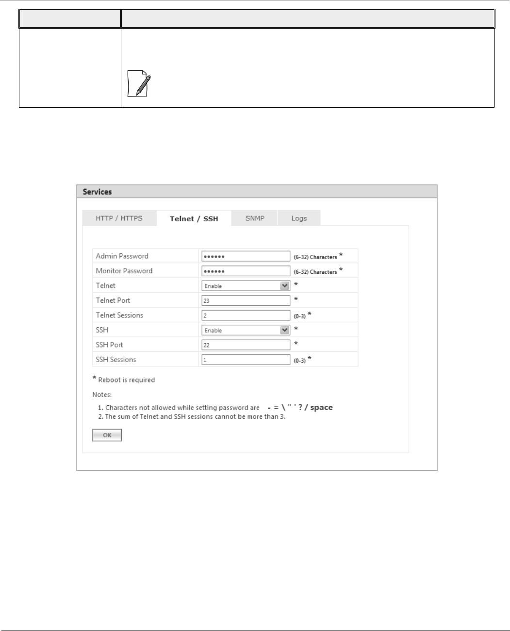
To configure Telnet/SSH interface parameters, navigate to MANAGEMENT > Services > Telnet / SSH.
Figure 6-19 Telnet/SSH
HTTPS By default, a user can manage the device through Web Interface over secure socket Layer
(HTTPS). To prevent access to the device through HTTPS, select Disable.
: The password configuration for HTTPS is same as configured for HTTP.
Parameter Description

Management
Tsunami® 800 & 8000 Series - Software Management Guide 210
Given below is the table which explains Telnet/SSH parameters and the method to configure the configurable parameter(s):
After configuring the required parameters, click OK, COMMIT and then REBOOT.
Parameter Description
Admin Password By default, the Administrator password to access Telnet/SSH interface is public. For
security reasons, it is recommended to change the default password. The password should
be alphanumeric with minimum of 6 and maximum of 32 characters.
: The following special characters are not allowed in the password:
- = \ “ ‘ ? / space
Monitor Password The Administrator user has the privilege to change the Monitor user password. By default,
the Monitor user password to access Telnet/SSH interface is public. For security reasons it
is recommended to change the default password. The password should be alphanumeric
with minimum of 6 and maximum of 32 characters.
: The following special characters are not allowed in the password:
- = \ “ ‘ ? / space
Telnet By default, a user can manage the device through Telnet. To prevent access to the device
through Telnet, select Disable.
Telnet Port Represents the port to manage the device using Telnet. By default, the Telnet port is 23.
Telnet Sessions The number of Telnet sessions which controls the number of active Telnet connections. A
user is restricted to configure a maximum of 3 Telnet sessions. By default, the number of
Telnet sessions allowed is 2.
SSH By default, a user can manage the device through SSH. To prevent access to the device
through SSH, select Disable.
SSH Port Represents the port to manage the device using Secure Shell. By default, the Secure Shell
port is 22.
SSH Sessions Represents the number of SSH sessions which controls the number of active SSH
connections. A user is restricted to configure a maximum of 3 SSH sessions. By default, the
number of SSH sessions allowed is 1.
: The total number of CLI sessions allowed is 3, so the sum of Telnet and SSH
sessions cannot be more than 3. For example, if you configure the number of
Telnet sessions as 2, then the number of SSH sessions can only be a value 0 or 1.
Management
Tsunami® 800 & 8000 Series - Software Management Guide 211
6.3.3 SNMP
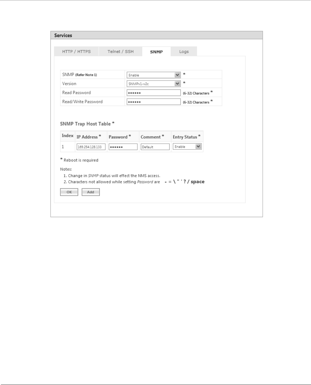
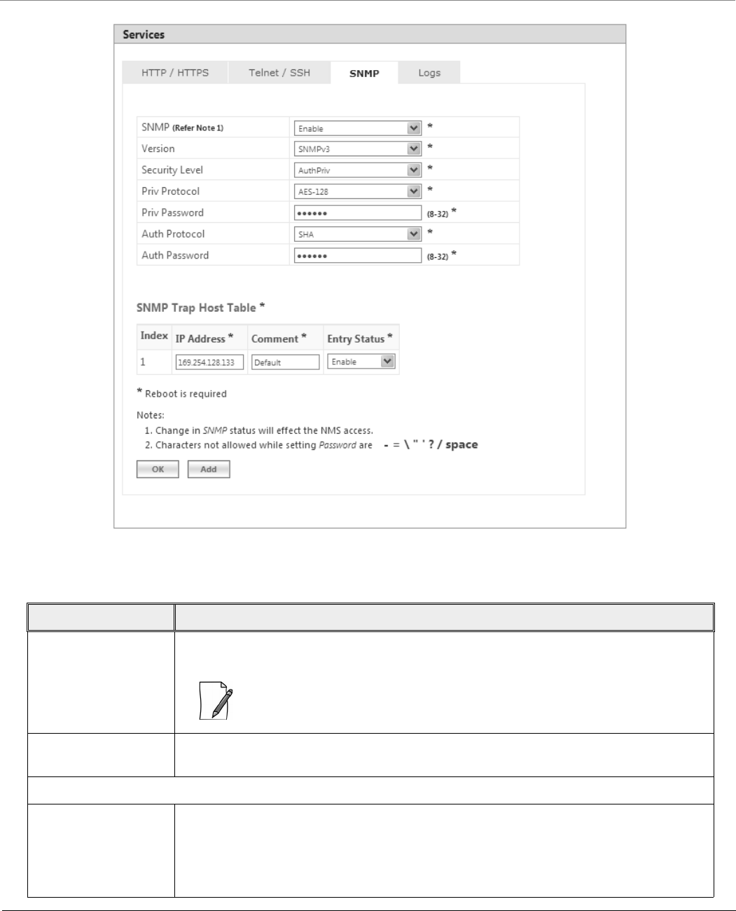
To configure SNMP interface parameters, navigate to MANAGEMENT > Services > SNMP.
Figure 6-20 SNMPv1-v2c
Management
Tsunami® 800 & 8000 Series - Software Management Guide 212
Figure 6-21 SNMPv3
Given below is the table which explains SNMP parameters and the method to configure the configurable parameter(s):
Parameter Description
SNMP By default, the user has the access to manage the device through SNMP Interface. To
prevent access to the device through SNMP, select Disable.
: Any change in the SNMP status will affect the Network Management System
access.
Version Allows you to configure the SNMP version. The supported SNMP versions are v1-v2c and
v3. By default, the SNMP version is v1-v2c.
SNMP v1-v2c Specific Parameters
Read Password Represents the read only community string used in SNMP Protocol. It is sent along with
each SNMP GET / WALK / GETNEXT / GETBULK request to allow or deny access to the
device. This password should be same as read password set in the NMS or MIB browser.
The default password is “public”. The password should be of minimum 6 and maximum
32 characters.
Management
Tsunami® 800 & 8000 Series - Software Management Guide 213
After configuring the required parameters, click OK, COMMIT and then REBOOT.
: The following special characters are not allowed in the password:
- = \ “ ‘ ? / space
Read/Write Password Represents the read-write community string used in SNMP Protocol. It is sent along with
each SNMP GET / WALK / GETNEXT / SET request to allow or deny access to the device.
This password should be same as read-write password set in the NMS or MIB browser. The
default password is “public”. The password should be of minimum 6 and maximum 32
characters.
: The following special characters are not allowed in the password:
- = \ “ ‘ ? / space
SNMP v3 Specific Parameters
Security level The supported security levels for the device are AuthNoPriv and AuthPriv. Select
AuthNoPriv for Extensible Authentication or AuthPriv for both Authentication and
Privacy (Encryption).
Priv Protocol Applicable only when the Security Level is set to AuthPriv.
Represents the type of privacy (or encryption) protocol. Select the encryption standard as
either AES-128 (Advanced Encryption Standard) or DES (Data Encryption Standard). The
default Priv Protocol is AES-128.
: The following special characters are not allowed in the password:
- = \ “ ‘ ? / space
Priv Password Applicable only when the Security Level is set to AuthPriv.
Represents the pass key for the selected Privacy protocol. The default password is
public123. The password should be of minimum 8 and maximum 32 characters.
: The following special characters are not allowed in the password:
- = \ “ ‘ ? / space
Auth Protocol Represents the type of Authentication protocol. Select the encryption standard as either
SHA (Secure Hash Algorithm) or MD5 (Message-Digest algorithm). The default Auth
Protocol is SHA.
Auth Password Represents the pass key for the selected Authentication protocol. The default password is
public123. The password should be of minimum 8 and maximum 32 characters.
Parameter Description
Management
Tsunami® 800 & 8000 Series - Software Management Guide 214
6.3.3.1 SNMP Trap Host Table
The SNMP Trap Host table allows you to add a maximum of 5 Trap server’s IP address to which the SNMP traps will be
delivered. By default, the SNMP traps are delivered to 169.254.128.133.
: The default SNMP Trap Host Table entry cannot be deleted.
To add entries to the Trap Host Table, click Add in the Services screen. The SNMP Trap Host Table Add Row screen
appears:
Figure 6-22 Add Entries to SNMP Host Table
Configure the following parameters:
IP Address: Based on the IP mode, enter the IPv4 or IPv6 address of the Trap server to which SNMP traps will be
delivered.
: IPv6 address should be the global IP address and not the link local IP address.
Password: Type the password to authenticate the Trap Server. The following special characters are not allowed in the
password: - = \ “ ‘ ? / space
: Applicable only to SNMP v1-v2c.
Comment: Type comments, if any.
Entry Status: Select the entry status as either Enable or Disable. If enabled, the device will send SNMP traps to the
authenticated Trap Server.
After configuring the required parameters, click Add and then COMMIT.
6.3.3.2 Edit SNMP Trap Host Table
Edit the desired SNMP Trap Host Table entries and click OK, COMMIT and then REBOOT.
Management
Tsunami® 800 & 8000 Series - Software Management Guide 215
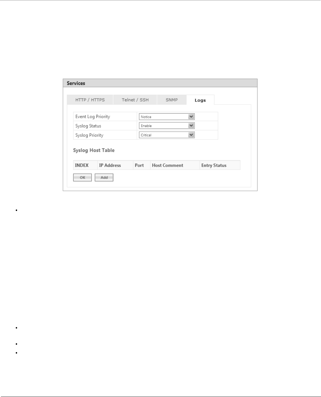
6.3.4 Logs
The device supports two types of log mechanisms:
1. Event Log: Based on the configured event log priority, all the log messages are logged and used for any analysis. This
log messages remain until they are cleared by the user.
2. Syslog: They are similar to Event logs except that they are cleared on device reboot.
To configure Event log and Syslog priority, navigate to MANAGEMENT > Services > Logs. The following screen appears:
Figure 6-23 Logs
Event Log Priority: By default, the priority is set to Notice. You can configure the event log priority as one of the
following:
– Emergency
– Alert
– Critical
– Error
– Warning
– Notice
– Info
– Debug
Please note that the priorities are listed in the order of their severity, where Emergency takes the highest severity and
Debug the lowest. When the log priority is configured as high, all the logs with low priority are also logged. For
example, if Event Log Priority is set to Notice, then the device will log all logs with priorities Notice, Warning, Error,
Critical, Alert and Emergency.
Syslog Status: By default, Syslog Status is enabled and default priority is Critical. If desired, you can choose to
disable.
Syslog Priority: Configuration is same as Event Log Priority.
After configuring the required parameters, click OK and then COMMIT.
Management
Tsunami® 800 & 8000 Series - Software Management Guide 216
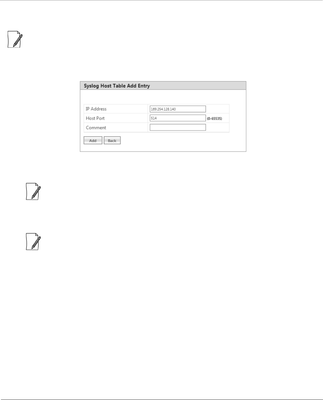
6.3.4.1 Configure a Remote Syslog host
Configure a syslog host (server) in order to forward syslog messages to it.
: You can configure only one syslog host.
Follow the following steps to configure a remote syslog host:
1. Click Add in the Syslog Host Table screen. The Syslog Host Table Add Row screen appears:
Figure 6-24 Syslog Host Table Add Row
2. IP Address: Based on the IP mode, enter IPv4 or IPv6 address of the Syslog host.
: IPv6 address should be the global IP address and not the link local IP address.
3. Host Port: Represents the port on which the Syslog host listens to the log messages sent by the device. The default
port is 514.
: The user must configure the correct port number on which the Syslog host is running. Choice of port number
must be in line with the standards for port number assignments defined by Internet Assigned Numbers
Authority (IANA).
4. Comments: Types comments, if any.
5. Click Add. The syslog host is added to the Syslog Host Table.
Management
Tsunami® 800 & 8000 Series - Software Management Guide 217
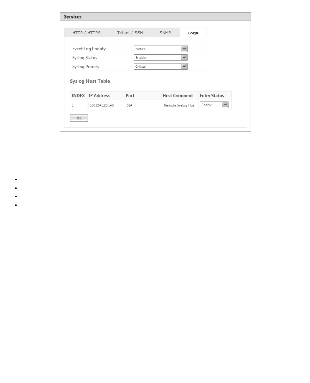
Figure 6-25 Syslog Host Configured
For some reason, if the configured syslog host parameters are changed then you can edit it directly in the Syslog Host Table
entry. You can change the following parameters:
IP Address
Port
Host Comments
Entry Status:
–Enable: By default, the configured Syslog host is enabled on the device.
–Disable: To disable an entry in the Syslog Host Table, click Disable.
–Delete: To delete the configured Syslog host, click Delete.
After doing the necessary changes, click OK followed by COMMIT.
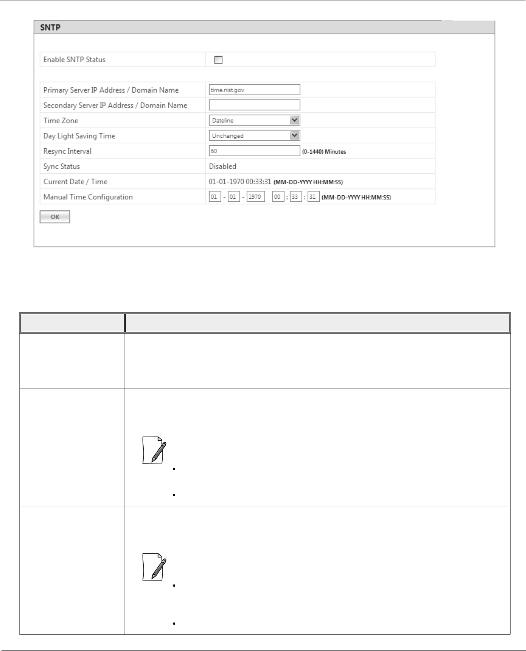
6.4 Simple Network Time Protocol (SNTP)
Proxim’s point-to-multipoint and point-to-point devices are furnished with Simple Network Time Protocol (SNTP) Client
software that enables to synchronize device’s time with the network time servers.
The SNTP Client when enabled on the device(s), sends an NTP (Network Time Protocol) request to the configured time servers.
Upon receiving the NTP response, it decodes the response and sets the received date and time on the device after adjusting
the time zone and day light saving.
In case, the time servers are not available, then users also have the option to manually set the date and time on the device.
To synchronize device’s time with time servers or manually set the time, navigate to MANAGEMENT > SNTP. The SNTP
screen appears:
Management
Tsunami® 800 & 8000 Series - Software Management Guide 218
Figure 6-26 Time Synchronization
Given below is the table which explains SNTP parameters and the method to configure the configurable parameter(s):
Parameter Description
Enable SNTP Status Select this parameter to enable SNTP Client on the device. If enabled, the SNTP Client tries
to synchronize the device’s time with the configured time servers.
By default, the SNTP status is disabled.
Primary Server IP
Address/Domain
Name
Enter the host name, or the IP address based on IP modes (IPv4 only or IPv4 and IPv6) of
the primary SNTP time server. The SNTP Client tries to synchronize device’s time with the
configured primary server time.
:
If host name is configured, instead of IP address then make sure that DNS
server IP is configured on the device.
IPv6 address should be the global IP address and not the link local IP address.
Secondary Server IP
Address/Domain
Name
Enter the host name, or the IP address based on IP modes (IPv4 only or IPv4 and IPv6) of
the secondary SNTP time server. If the primary server is not reachable, then SNTP client tries
to synchronize device’s time with the secondary server time.
:
If the SNTP client is not able to sychronize the time with both the servers
(primary and secondary), then it tries to synchronize again after every one
minute.
IPv6 address should be the global IP address and not the link local IP address.

Management
Tsunami® 800 & 8000 Series - Software Management Guide 219
To save the configured parameters, click OK and then COMMIT.
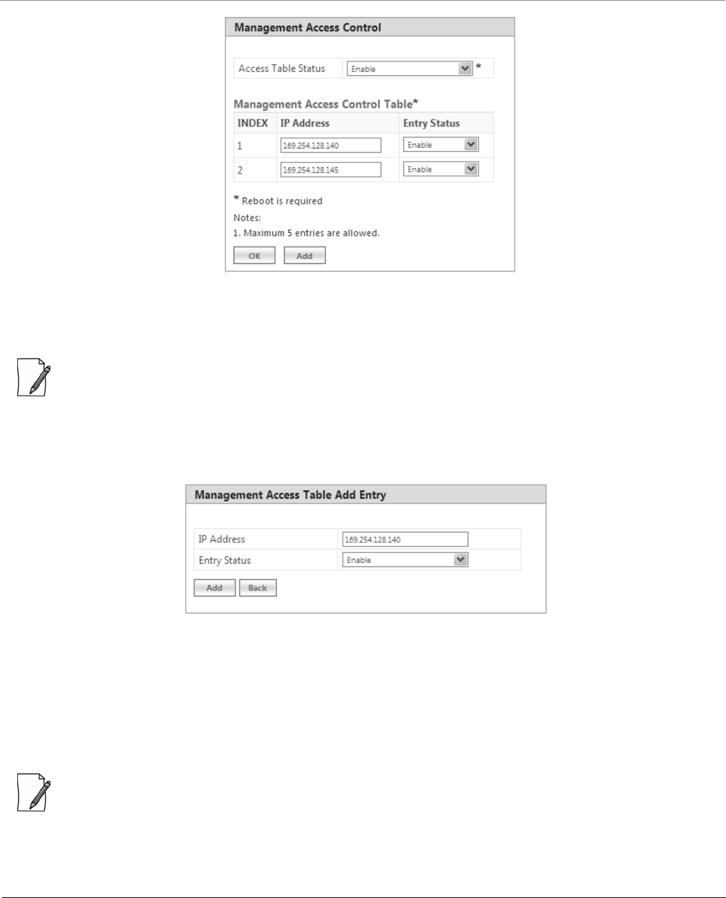
6.5 Access Control
The Access Control tab enables you to control the device management access through specified host(s). You can specify a
maximum of five hosts to control device management access.
To configure management access control parameters, navigate to MANAGEMENT > Access Control. The Management
Access Control screen appears:
Time Zone Configure the time zone from the available list. This configured time zone is considered
before setting the time, received from the time servers, on the device.
Day Light Saving Time Configure the Day Light Saving time from the available list. This configured Day Light
Saving time is considered before setting the time, received from the time servers, on the
device.
ReSync Interval Set ReSync time interval ranging from 0 to 1440 minutes. Once the time is synchronized,
the SNTP Client tries to resynchronize with the time servers after every set time interval.
By default, the ReSync interval is set to 60 minutes.
Sync Status Specifies the SNTP Client sync status when it tries to ReSync again with the time servers.
The status is as follows:
Disabled: The SNTP client will not synchronize the time with the time servers and
displays the status as Disabled.
Synchronizing: The SNTP client is in the process of synchronzing time with the time
servers.
Synchronized: The SNTP client has synchronized time with the time servers.
Current Date/Time Displays the current date and time.
If SNTP is enabled, it displays the time the device received from the SNTP server. If SNTP is
not enabled, then it displays the time manually set by the user.
Manual Time
Configuration
If SNTP Client is disabled on the device or the time servers are not available on the
network, then the user can manually set the time. Enter the time manually in the format:
MM-DD-YYYY HH:MM:SS.
:
Manual time configuration is not retained across reboots. After every reboot
the user has to set the time again.
Over a period of time, with manual time configuration, the device may lag
behind the actual time. So, it is recommended to periodically check and adjust
the time.
Parameter Description
Management
Tsunami® 800 & 8000 Series - Software Management Guide 220
Figure 6-27 Management Access Control
By default, the Management Access Control feature is disabled on the device. To enable, select Enable from the Access
Table Status box and click OK. Reboot the device, for the changes to take effect.
: Only when the Access Table Status is enabled, you can add host(s) to the Management Access Control Table.
6.5.0.1 Add Host(s) to Management Access Control Table
To add a host to the Management Access Control Table, do the following:
1. Click Add in the Management Access Control screen. The Management Access Table Add Row screen appears:
Figure 6-28 Management Access Table Add Row
2. IP Address: Based on the IP mode, configure either IPv4 or IPv6 address of the host that controls the device
management access.
3. Entry Status: By default, the entry status is enabled meaning which the specified host can control the device
management access. Edit the status to Disable, if you do not want the host to control the device management
access.
4. Click Add.
: If MAC ACL is enabled, configure at least one entry in the Management Access Table with the IP address (of the PC or
the management station), in order to manage the device.
6.5.0.2 Edit Management Access Control Table Entries
Edit the desired host entries and click OK, COMMIT and then REBOOT.
Management
Tsunami® 800 & 8000 Series - Software Management Guide 221
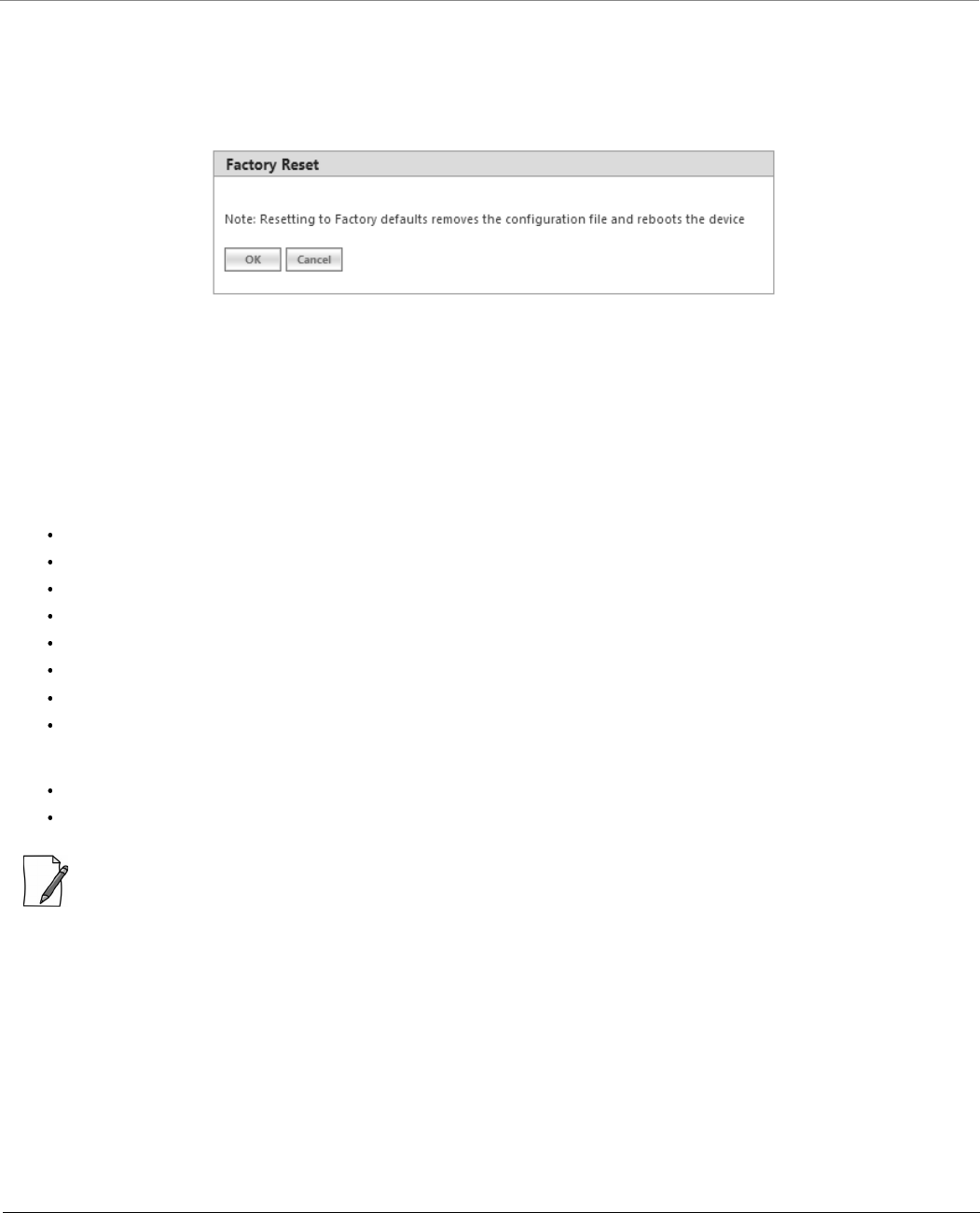
6.6 Reset to Factory
The Reset to Factory tab allows you to reset the device to its factory default state. When this operation is performed, the
device will reboot automatically and comes up with default configurations.
To reset the device to its factory defaults, navigate to MANAGEMENT > Reset To Factory. The Factory Reset screen appears:
Figure 6-29 Reset to Factory Defaults
Click OK, if you wish to proceed with factory reset, else click Cancel.
6.7 Convert QB to MP
The Convert QB to MP tab lets you convert a QB to SU so that the converted device can connect to a BSU and operate as a
SU.
This feature is applicable only to,
QB-8100-EPA which converts to a MP-8100-SUA
QB-8150-EPR which converts to a MP-8150-SUR
QB-8150-EPR-100 which converts to a MP-8150-SUR-100
QB-8200-EPA which converts to a MP-8200-SUA
QB-8250-EPR which converts to a MP-8250-SUR
QB-8151-EPR which converts to a SU
QB-825-EPR-50 which converts to a MP-825-CPE-50
QB-825-EPR-50+ which converts to a MP-825-SUR-50+
You can convert a QB to SU mode by using two methods:
Method 1: Web Interface
Method 2: Load an SU config file (retrieved from another SU) onto the QB device and then reboot.
: Even after conversion from QB to MP, the device description still shows as QB.
Management
Tsunami® 800 & 8000 Series - Software Management Guide 222
To convert a QB to SU using Web Interface, do the following:
1. Navigate to MANAGEMENT > Convert QB to MP. The Convert QB to MP screen appears:
Figure 6-30 Convert QB to MP
2. Click OK.
3. Reboot the device for the changes to take effect.
:
A QB after converting to SU will function in SU mode only. It will accept only MP firmware for upgrade.
The version of the firmware being upgraded to should be 2.4.0 or later. If earlier version of the firmware is loaded,
the device will reset to factory default upon initialization and operate in QB mode.
When upgrading a converted device from Bootloader, it must be done using a QB image, as the device is licensed as
QB.
The conversion of the device from QB to SU requires a reboot.
In case of Method 1 (Web Interface) conversion, QB mode configuration will be deleted.
Reset to factory defaults, always results in the device initializing in QB mode.
Tsunami® 800 & 8000 Series - Software Management Guide 223
Monitor
This chapter contains information on how to monitor the device by using Web interface. It contains information on the
following:
7.1 System
The System tab enables to view system specific information such as LED/RSSI Display.
: 'RSSI LED' feature is applicable only to 82x devices.
To view LED/RSSI Display, navigate to MONITOR > System. The LED/RSSI Display screen appears:
Figure 7-1 LED/RSSI Display
When the link is established, Received Signal Strength Indicator (RSSI) LEDs on the scaling mask glow. Scaling mask LEDs
indicate the received signal strength of the link. The more LEDs on the scaling mask glow, better is the signal.
To select the LED Display Status, navigate to Advanced Configuration > System. By default, RSSI Display mode is
enabled, if required the user can select the Disable (LEDs Off) mode. In Disable (LEDs Off) mode, all the 5 LEDs will be off.
– The LED behavior in RSSI Display mode is given below:
By default all the 5 LEDs will blink for an interval of 1 second to indicate the device is UP.
For a BSU, in order to monitor the SU link statistics, the user should first configure the wireless MAC address of
the SU. If the configured SU is registered with the BSU, then the LEDs will glow based on the RSSI value else all
the 5 LEDs will blink.
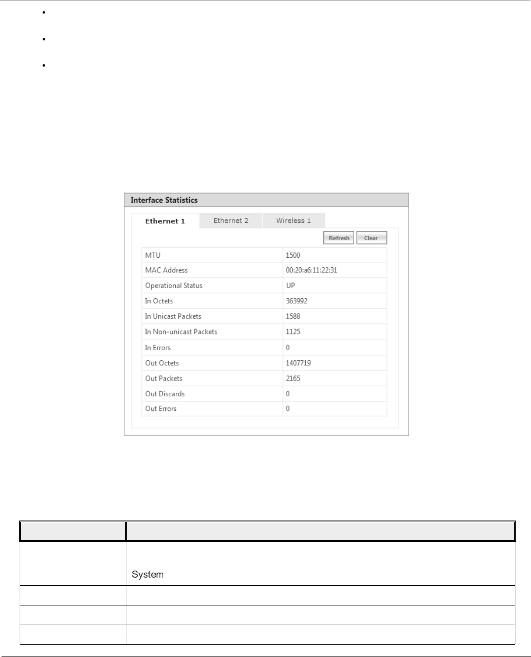
Monitor
Tsunami® 800 & 8000 Series - Software Management Guide 224
For a SU, if the SU is registered with the BSU, then the LEDs will glow based on the RSSI value else all the 5 LEDs
will blink.
For a CPE, if the CPE is registered with the BSU, then the LEDs will glow based on the RSSI value else all the 5 LEDs
will blink.
For QB, if EndPointA is registered with EndPointB, then the LEDs will glow based on the RSSI value of each
EndPoint. else all the 5 LEDs will blink.
7.2 Interface Statistics
Interface Statistics allows you to monitor the status and performance of the Ethernet and Wireless interfaces of the device.
7.2.1 Ethernet Statistics
To view the Ethernet interface statistics, click MONITOR > Interface Statistics. The Interface Statistics screen appears:
Figure 7-2 Ethernet Interface Statistics
To view Ethernet statistics, click Ethernet 1 or Ethernet 2 depending on the Ethernet interfaces supported by your device.
Given below is the table which explains the parameters displayed in the Ethernet Statistics screen:
Parameter Description
MTU Specifies the largest size of the data packet received or sent on the Ethernet interface.
The MTU size varies from 1500 to 1514 depending on the MTU configuration (See
).
MAC Address Specifies the MAC address at the Ethernet protocol layer.
Operational Status Specifies the current operational state of the Ethernet interface.
In Octets Specifies the total number of octets received on the Ethernet interface.

Monitor
Tsunami® 800 & 8000 Series - Software Management Guide 225
To view the updated Ethernet statistics, click Refresh.
To delete the Ethernet statistics, click Clear.
In Unicast Packets Specifies the number of subnetwork- unicast packets delivered to the higher level
protocol.
In Non-unicast Packets Specifies the number of non-unicast subnetwork packets delivered to the higher level
protocol.
In Errors Specifies the number of inbound packets that contained errors and are restricted from
being delivered.
Out Octets Specifies the total number of octets transmitted out from the Ethernet interface.
Out Packets Specifies the total number of packets requested by the higher level protocol and then,
transmitted.
Out Discards Specifies the number of error-free outbound packets chosen to be discarded to prevent
them from being transmitted. One possible reason for discarding such a packet could be
to free up buffer space.
Out Errors Specifies the number of outbound packets that are not transmitted because of errors.
Parameter Description
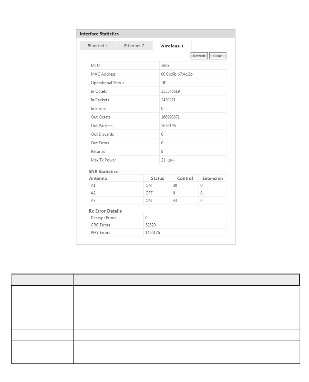
Monitor
Tsunami® 800 & 8000 Series - Software Management Guide 226
7.2.2 Wireless Statistics
To view the Wireless interface statistics, click MONITOR > Interface Statistics > Wireless1.
Figure 7-3 Wireless Interface Statistics
Given below is the table which explains the parameters displayed in the Wireless statistics screen:
Parameter Description
MTU Specifies the largest size of the data packet received or sent on the wireless interface.
The MTU size can range from 350 to 3808 bytes for High throughput modes and 350 to
2304 bytes for legacy mode. The default and maximum value of the WORP MTU is 3808
bytes for higher throughput and 2304 bytes for legacy mode.
MAC Address Specifies the MAC address at the wireless protocol layer.
Operational Status Specifies the current operational state of the wireless interface.
In Octets Specifies the total number of octets received on the wireless interface.
In Packets Specifies the number of packets delivered to the higher level protocol.

Monitor
Tsunami® 800 & 8000 Series - Software Management Guide 227
To view the updated Wireless statistics, click Refresh.
To delete the Wireless statistics, click Clear.
7.2.3 PPPoE Statistics
: Applicable only to an SU in Routing mode.
To view PPPoE interface statistics, navigate to MONITOR > Interface Statistics > PPPoE > PPP Interface Stats.
In Errors Specifies the number of inbound packets that contained errors and are restricted from
being delivered.
Out Octets Specifies the total number of octets transmitted out from the wireless interface.
Out Packets Specifies the total number of packets requested by the higher level protocol and then,
transmitted.
Out Discards Specifies the number of error-free outbound packets chosen to be discarded to prevent
them from being transmitted. One possible reason for discarding such a packet could be
to free up buffer space.
Out Errors Specifies the number of outbound packets that are not transmitted because of errors.
Retunes Specifies the number of times the radio is re-tuned for better performance of the device.
Max Tx Power Indicates the maximum power that the radio can radiate.
SNR Statistics
SNR Statistics represents the signal strength with regard to the noise at the antenna ports.
Antenna Specifies the antenna ports available for the product. Please note that the antenna ports
vary depending on the product.
Status Specifies the configuration status of the antenna ports. ON indicates that antenna port is
enabled and OFF indicates that antenna port is disabled.
Control Specifies the SNR value of the packet received at the selected channel frequency.
Extension This parameter is applicable only to the 40 MHz modes, that is, 40 PLUS and 40 Minus.
It specifies the SNR value of the packet received on the extension channel (20MHz).
Rx Error Details
Decrypt Errors This parameter is applicable only if security is enabled. It indicates the number of received
packets that failed to decrypt.
CRC Errors Specifies the number of received packets with invalid CRC.
PHY Errors Specifies the total Rx PHY Errors. It generally indicates the interference in the wireless
medium.
Parameter Description
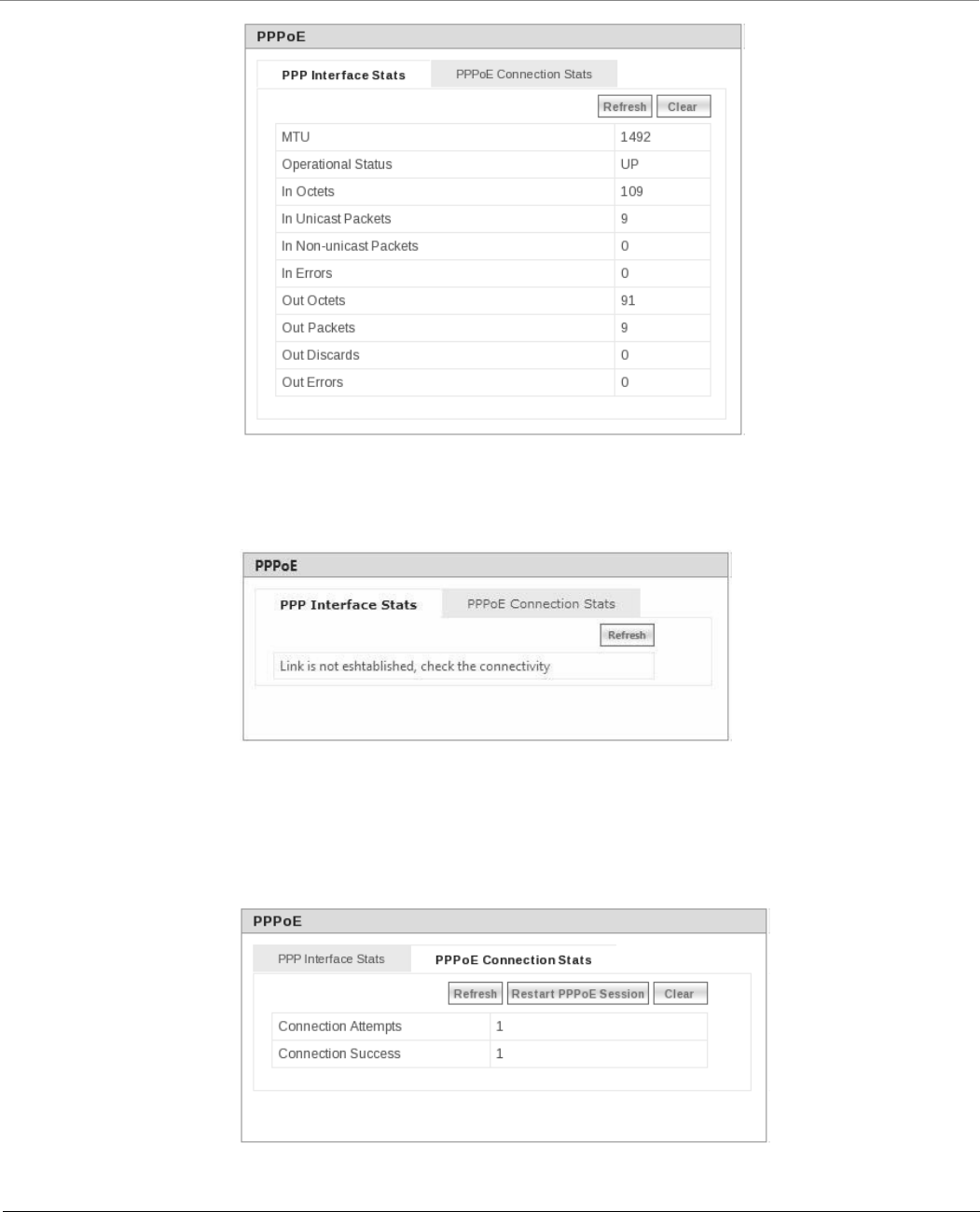
Monitor
Tsunami® 800 & 8000 Series - Software Management Guide 228
Figure 7-4 PPPoE Interface Statistics
The PPPoE interface parameters are same as the Ethernet interface parameters. Please note that if a link is not established
between a PPPoE client and server, then the device displays the following message.
Figure 7-5 PPPoE Server - No Link Established
To view the updated PPPoE interface statistics, click Refresh. Please note that for every 4 seconds, the interface statistics gets
refreshed.
To view the PPPoE connection status such as the number of attempts made to start a session between PPPoE client and server,
and the number of attempts failed to establish a connection, click PPPoE Connection Stats.
Figure 7-6 PPPoE Connection Statistics
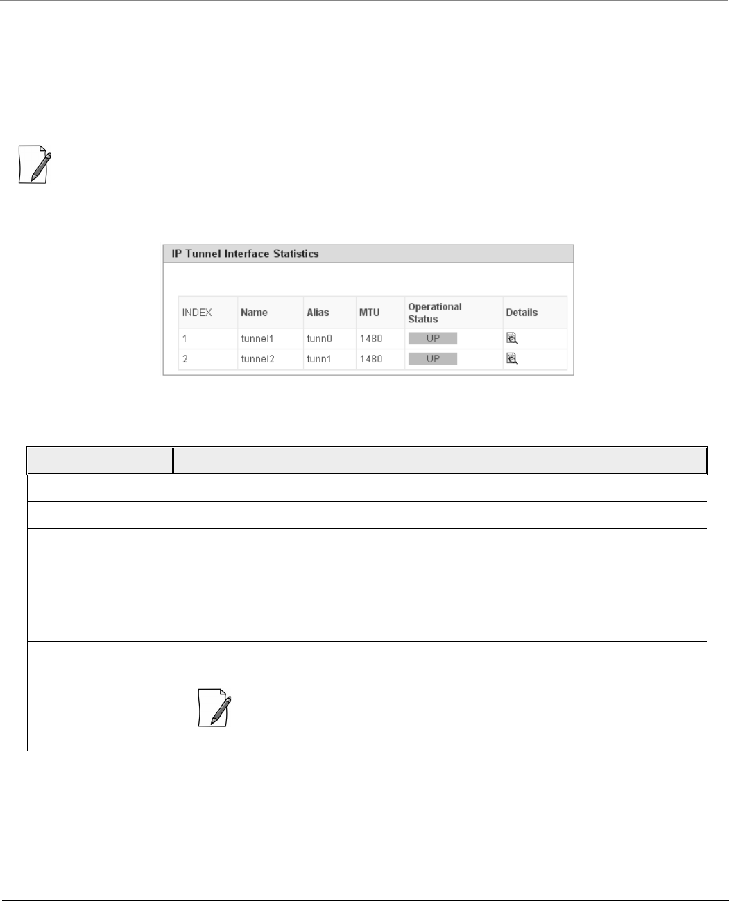
Monitor
Tsunami® 800 & 8000 Series - Software Management Guide 229
To view updated connection statistics, click Refresh.
To restart the session between the PPPoE client and server, click Restart PPPoE Session. On successfully re-establishing a
session, the IP address of the wireless interface will be assigned again by the PPPoE server, if Address Type is set to PPPoE-ipcp.
To clear the existing connection statistics, click Clear.
7.2.4 IP Tunnels
: Applicable only in Routing Mode.
To view IP Tunnels interface statistics, click MONITOR > Interface Statistics > IP Tunnels. The following IP Tunnel
Interface Statistics screen appears:
Figure 7-7 IP Tunnels Interface Statistics
Given below is an explanation to each of these parameters:
Parameter Description
Name Specifies the tunnel interface name.
Alias Specifies the supplementary tunnel interface name.
Maximum
Transmission Unit
(MTU)
Specifies the largest size packet or frame that can be sent over the tunnel interface.
The MTU of the tunnel interface is derived from the underlying interface:
For IP-IP tunnel interface: MTU = Underlying interface MTU – 20 bytes (IP header)
For IP-GRE interface: MTU = Underlying interface MTU – 24 bytes (IP header + gre
protocol)
Operational Status The Operational Status indicates only the tunnel interface status. The status can be either
UP or DOWN.
: For the tunnel to function correctly both ends should be configured correctly.
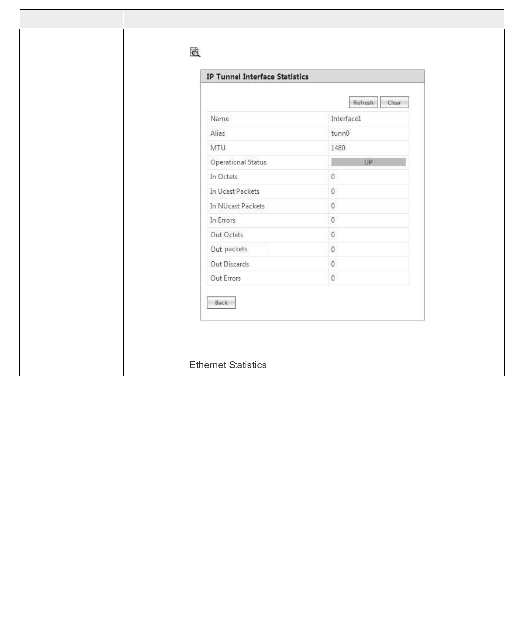
Monitor
Tsunami® 800 & 8000 Series - Software Management Guide 230
7.3 WORP Statistics
7.3.1 General Statistics
WORP General Statistics provides general statistics about the WORP.
To view General Statistics, navigate to MONITOR > WORP Statistics > Interface 1 > General Statistics. The following
WORP General Statistics screen appears.
Details Provides a more detailed statistics about the tunnel interface. To view the detailed
statistics, click .
Figure 7-8 Detailed IP Tunnels Interface Statistics
The detailed tunnel interface parameters are similar to the Ethernet Interface Statistics.
Please refer to .
Parameter Description
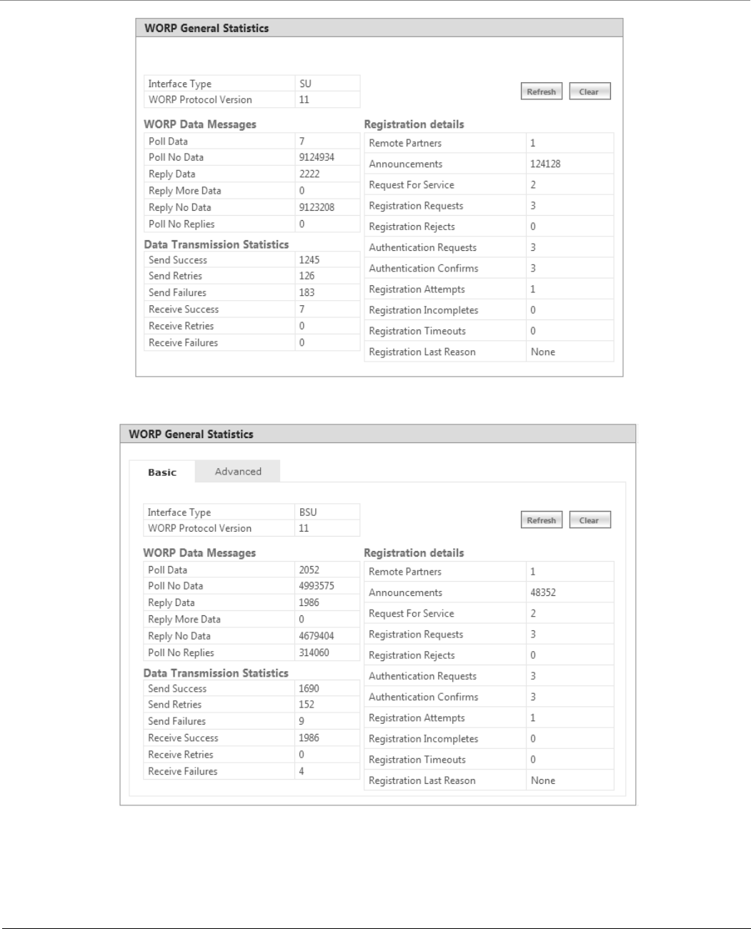
Monitor
Tsunami® 800 & 8000 Series - Software Management Guide 231
Figure 7-9 WORP General Statistics (SU/End Point A/End Point B)
Figure 7-10 WORP General Statistics (BSU)

Monitor
Tsunami® 800 & 8000 Series - Software Management Guide 232
7.3.1.1 Basic Statistics
Given below is an explanation to the basic parameters:
Parameter Description
Interface Type Specifies the type of radio interface.
WORP Protocol
Version
Specifies the version of the WORP Protocol used. This information is useful to the customer
support team for debugging purpose only.
WORP Data Messages
Specifies the sent or received data frames through wireless interface.
Poll Data Refers to the number of polls with data messages sent or received.
Poll No Data Refers to the number of polls with no data messages sent or received.
Reply Data Refers to the number of poll replies with data messages sent or received.
Reply More Data Refers to the number of poll replies with more data messages sent or received.
Reply No Data Refers to the number of poll replies with no data messages sent or received.
Poll No Replies Refers to the number of times the poll messages are sent by a BSU/End Point A and
received no reply from SU/End Point B. This parameter is applicable only to a BSU.
Data Transmission Statistics
Specifies the number of transmissions occurred through the interface.
Send Success Refers to the number of data messages sent and acknowledged by the peer successfully.
Send Retries Refers to the number of data messages that are re-transmitted and acknowledged by the
peer successfully.
Send Failures Refers to the number of data messages that are not acknowledged by the peer even after
the specified number of retransmissions.
Receive Success Refers to the number of data messages received and acknowledged successfully.
Receive Retries Refers to the number of successfully received re-transmitted data messages.
Receive Failures Refers to the number of data messages that were not received successfully.
Registration Details
Specifies the status of the entire registration process.
Remote Partners Refers to the number of remote partners. For an SU/End Point A/End Point B, the number
of remote partners is always zero or one.
Announcements Refers to the number of Announcement messages sent or received on WORP interface.
Request For Service Refers to the number of requests for service messages sent or received.
Registration Requests Refers to the number of registration request messages sent or received on WORP interface.
Registration Rejects Refers to the number of registration reject messages sent or received on WORP interface.
Authentication
Requests
Refers to the number of authentication request messages sent or received on WORP
interface.
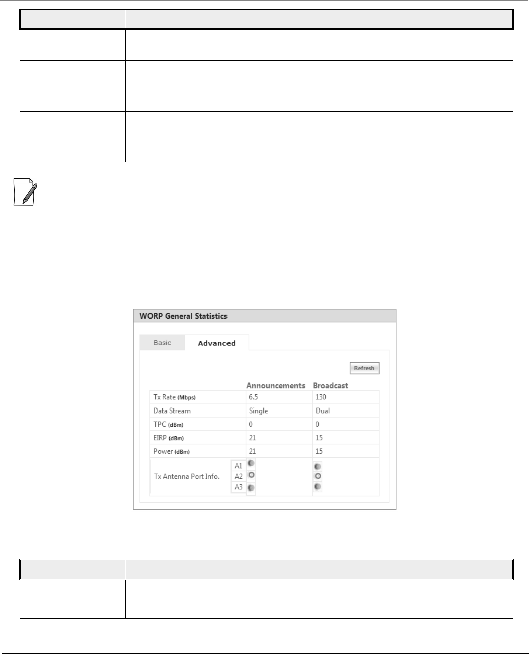
Monitor
Tsunami® 800 & 8000 Series - Software Management Guide 233
: For better results, the Send Failure or Send Retrieve must be low in comparison to Send Success. The same applies for
Receive Retries or Receive Failure.
Click Clear to delete existing general statistics. Click Refresh to view updated WORP general statistics.
7.3.1.2 Advanced Statistics
Advanced statistics is applicable only to the BSU. The Advanced Statistics screen displays the wireless transmission values
used by the BSU to send announcement and broadcast messages.
Figure 7-11 WORP Advanced Statistics
Given below is an explanation to the advanced parameters:
Authentication
Confirms
Refers to the number of authentication confirm messages sent or received on WORP
interface.
Registration Attempts Refers to the number of times a registration attempt has been initiated.
Registration
Incompletes
Refers to the number of registration attempts that are not yet completed.
Registration Timeouts Refers to the number of times the registration procedure timed out.
Registration Last
Reason
Refers to the reason for the last registration getting aborted or failed.
Parameter Description
Tx Rate Displays the Data Transmission Rate used by the BSU.
Data Stream Displays the Data Streams used by the BSU.
Parameter Description
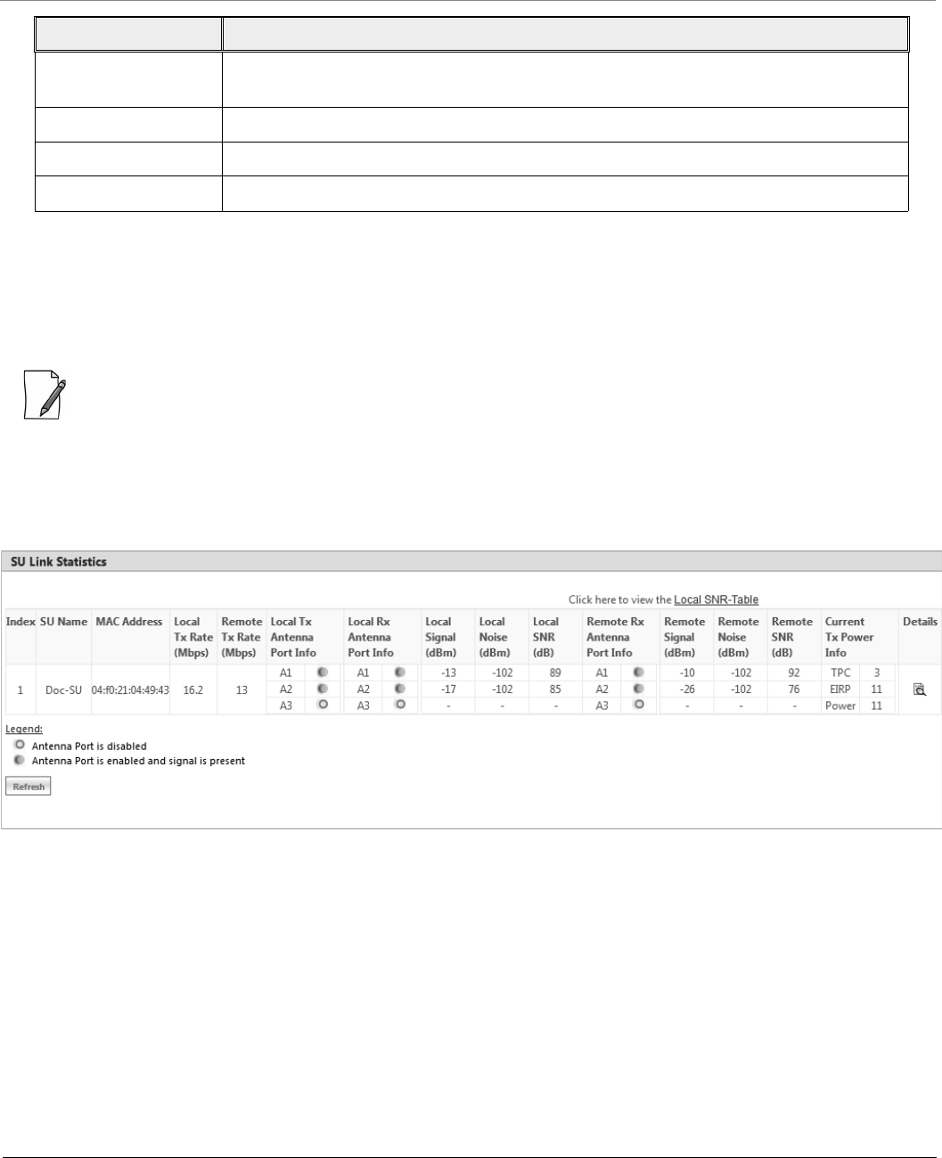
Monitor
Tsunami® 800 & 8000 Series - Software Management Guide 234
Click Refresh to view updated WORP advanced statistics.
7.3.2 Link Statistics
7.3.2.1 SU / End Point B Link Statistics
: SU Link Statistics is applicable only to a BSU, and End Point B Link Statistics is applicable only to a End Point A device.
SU Link statistics provides information about the SUs connected to a BSU. Similarly, End Point B Link Statistics provides
information about an End Point B currently connected to an End Point A device.
To view link statistics, navigate to MONITOR > WORP Statistics > Interface 1 > SU Link Statistics.
Figure 7-12 An Example - SU Link Statistics (For 82x Devices)
TPC Displays the TPC value currently applied by the device to adjust the transmit power
radiated by the radio.
EIRP Displays the current EIRP that a radio antenna radiates (after applying the TPC).
Power Displays the current transmit power radiated by the radio (after applying the TPC).
Tx Antenna Ports Indicates the status of the antenna ports at the BSU end.
Parameter Description
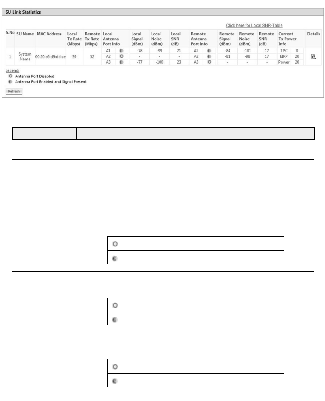
Monitor
Tsunami® 800 & 8000 Series - Software Management Guide 235
Figure 7-13 An Example - SU Link Statistics (For All Devices)
Given below is an explanation to each of these parameters:
Parameter Description
SU Name/
End Point B Name
Represents the name of the SU/End Point B connected to a BSU/End Point A respectively.
MAC Address Represents the MAC address of the SU/End Point B connected to a BSU/End Point A
respectively.
Local Tx Rate (Mbps) Represents the data transmission rate at the local (current device) end.
Remote Tx Rate
(Mbps)
Represents the data transmission rate at the remote (peer) end.
Local Antenna Port
Info
Indicates the status of the antenna ports at the local end. The following symbols indicate
the status of the antenna ports.
Local Tx Antenna Port
Info
Indicates the status of the antenna ports at the transmitting end. The following symbols
indicate the status of the antenna ports.
Local Rx Antenna Port
Info
Indicates the status of the antenna ports at the receiving end. The following symbols
indicate the status of the antenna ports.
Indicates the antenna port is disabled.
Indicates the antenna port is enabled and signal is present.
Indicates the antenna port is disabled.
Indicates the antenna port is enabled and signal is present.
Indicates the antenna port is disabled.
Indicates the antenna port is enabled and signal is present.

Monitor
Tsunami® 800 & 8000 Series - Software Management Guide 236
Click Refresh to view updated link statistics.
To view detailed SU/End Point B Link statistics, click Details icon in the SU/End Point B Link Statistics screen. The
following screen appears depending on your device:
Local Signal (dBm) Represents the signal level with which the device at the local end receives frames from the
device at the remote end, through wireless medium.
Local Noise (dBm) Represents the noise measured at the local end antenna ports.
Local SNR (dB) Represents the SNR measured by the receiver at the local end and is based on the Local
Signal and Local Noise.
Remote Rx Antenna
Port Info
Indicates the status of the remote end antenna ports. The antenna ports status is same as
explained in Local Antenna Port Info.
Remote Signal (dBm) Represents the signal level with which the device at the remote end receives frames,
through wireless medium.
Remote Noise (dBm) Represents the noise measured at the remote end antenna ports.
Remote SNR (dB) Represents the SNR measured by the receiver at the remote end and is based on the
Remote Signal and Remote Noise.
Current Tx Power
(dBm)
TPC: Displays the TPC value currently applied by the device to adjust the transmit
power radiated by the radio antenna.
: For a given data rate, if the configured TPC value is greater than the maximum
transmit power supported by the radio then maximum transmit power
supported by radio value is applied.
EIRP: Displays the current EIRP that a radio antenna radiates (after applying the TPC).
Power: Displays the current transmit power radiated by the radio (after applying the
TPC).
Parameter Description
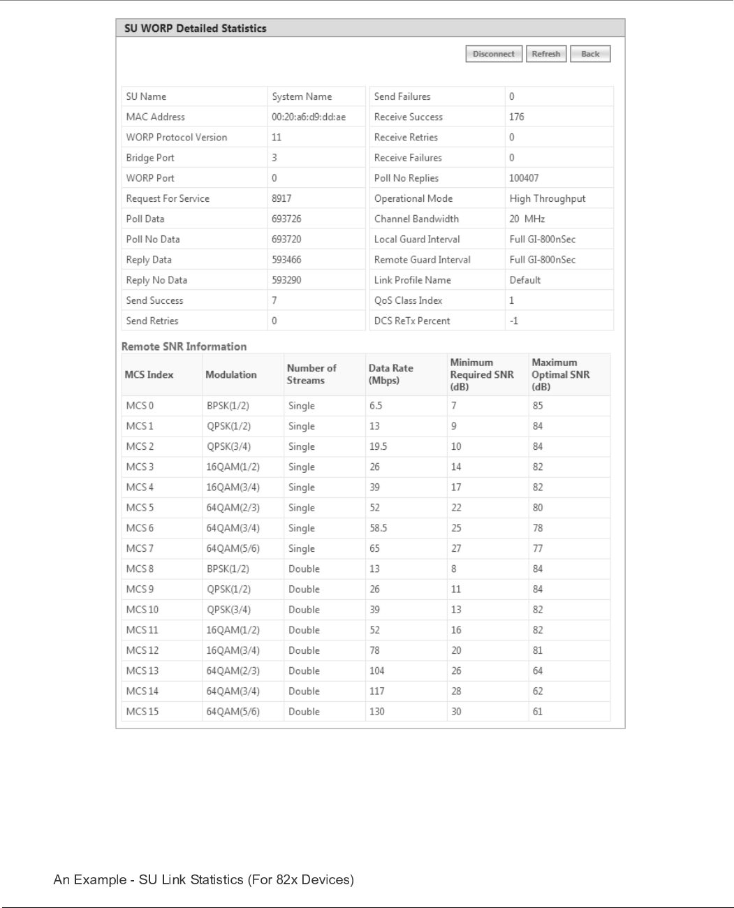
Monitor
Tsunami® 800 & 8000 Series - Software Management Guide 237
Figure 7-14 An Example - SU Detailed Statistics
The detailed page displays Remote SNR information, that is, the Minimum Required SNR and the Maximum Optimal SNR
value for a given data rate or modulation, to achieve optimal throughput.
To disconnect an SU/End Point B from BSU/End Point A respectively, click Disconnect.
To view updated detailed statistics, click Refresh.
To view local SNR table, click Click here for Local SNR-Table on the upper-right of SU/End Point B Link Statistics screen
(Refer ). The following screen appears depending on your device:
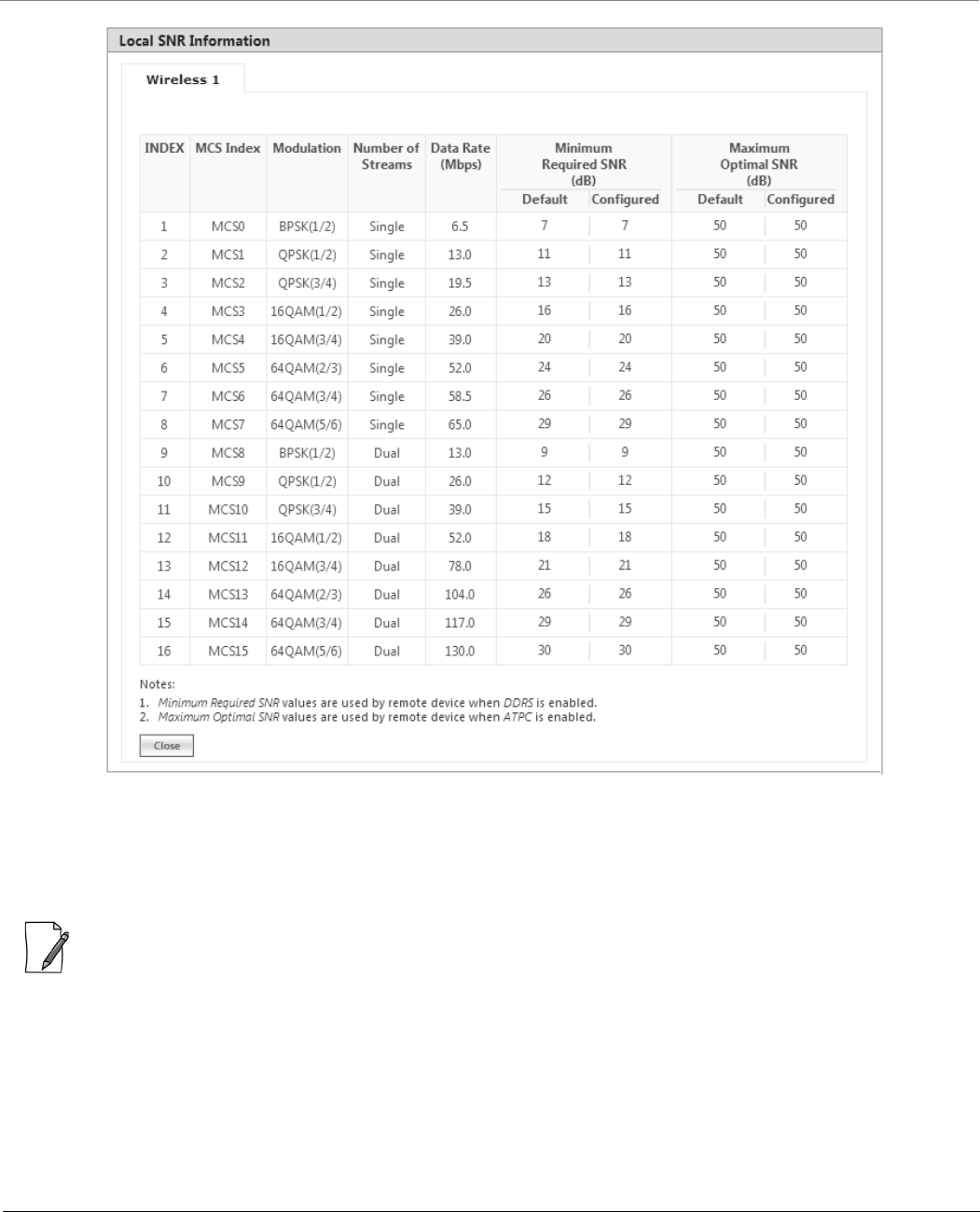
Monitor
Tsunami® 800 & 8000 Series - Software Management Guide 238
Figure 7-15 An Example - Local SNR Information
These configured values are used by ATPC and DDRS to derive TPC and data rate for optimal throughput.
7.3.2.2 BSU/End Point A Link Statistics
: BSU Link Statistics is applicable only to an SU, and End Point A Link Statistics is applicable only to an End Point B
device.
BSU Link statistics provides information about the BSU to which SUs are connected. Similarly, End Point A Link Statistics
provides information about an End Point A currently linked to an End Point B device.
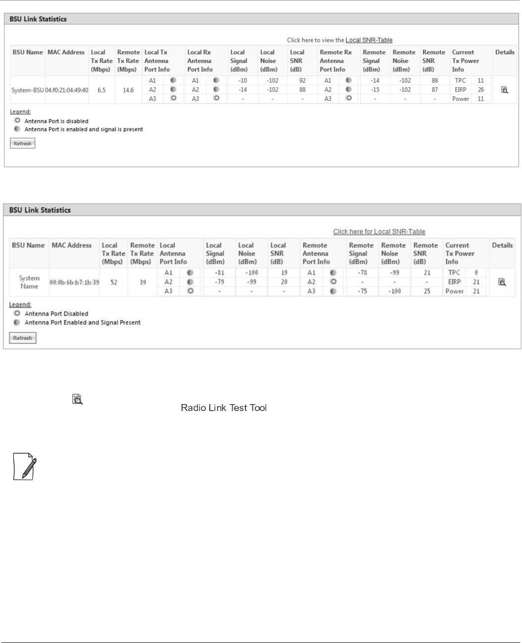
Monitor
Tsunami® 800 & 8000 Series - Software Management Guide 239
Figure 7-16 An Example - BSU Link Statistics (For 82x Devices)
Figure 7-17 An Example - BSU Link Statistics (For All Devices)
To access the Radio Link Test Tool, navigate to MONITOR > WORP Statistics > Interface 1 > SU/BSU Link Statistics >
Details. Click . The SU/BSU WORP Detailed Statistics screen appears. In this screen, click the Radio Link Test button.
For detailed description of this tool, refer .
7.3.3 QoS Statistics (BSU or End Point A Only)
: This parameter is applicable only to BSU or End Point A radio modes.
To view QoS Statistics, navigate to MONITOR > WORP Statistics > Interface 1 > QoS Statistics. The following QoS
Summary screen appears.
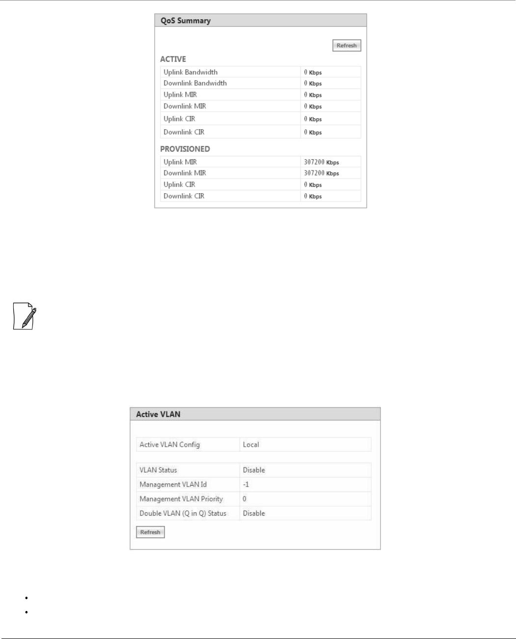
Monitor
Tsunami® 800 & 8000 Series - Software Management Guide 240
Figure 7-18 QoS Summary
This screen shows the total, minimum and maximum bandwidth allocated per BSU/End Point A, and the minimum and
maximum bandwidth allocated for each SU/End Point B registered with the BSU/End Point A respectively.
7.4 Active VLAN
: Active VLAN is applicable only to a device in SU (Bridge) mode.
The Active VLAN page enables you to identify the VLAN Configuration mode applied on a device in SU mode.
To view active VLAN applied on the device in SU mode, navigate to MONITOR > Active VLAN. The Active VLAN page
appears:
Figure 7-19 Active VLAN
The Active VLAN Config parameter helps you to identify the current VLAN configuration applied on the device in SU mode.
Local: VLAN configuration is done locally from the device.
Remote: VLAN configuration is done through RADIUS Server.
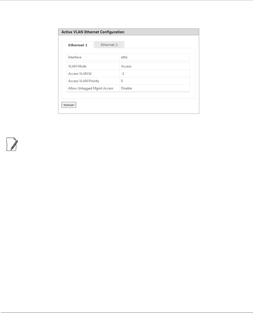
Monitor
Tsunami® 800 & 8000 Series - Software Management Guide 241
This page also displays the VLAN parameters and their values that are configured either locally or remotely.
To view active VLAN Ethernet Configuration, navigate to MONITOR > Active VLAN > Ethernet. The Active VLAN
Ethernet Configuration page appears:
Figure 7-20 Active VLAN Ethernet Configuration
This page displays the VLAN Ethernet parameters and their values that are configured either locally or remotely.
: Please note that the number of Ethernets vary depending on the device.
7.5 Bridge
7.5.1 Bridge Statistics
The Bridge Statistics allows you to monitor the statistics of the Bridge.
To view the Bridge Statistics, navigate to MONITOR > Bridge > Bridge Statistics. The following Bridge Statistics screen
appears:
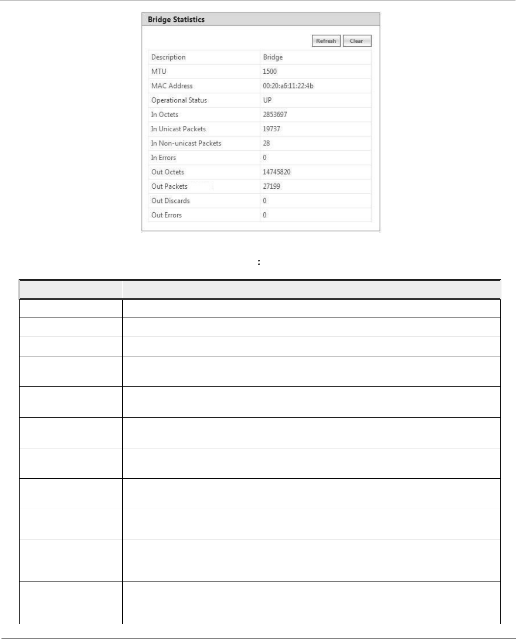
Monitor
Tsunami® 800 & 8000 Series - Software Management Guide 242
Figure 7-21 Bridge Statistics
The following table lists the parameters and their description
Parameter Description
Description This parameter provides a description about the bridge.
MTU Represents the largest size of the data packet sent on the bridge.
MAC Address Represents the MAC address at the bridge protocol layer.
Operational Status Represents the current operational status of the bridge: UP (ready to pass packets) or
DOWN (not ready to pass packets).
In Octets Represents the total number of octets received on the bridge interface, including the
framing characters.
In Unicast Packets Represents the number of unicast subnetwork packets delivered to the higher level
protocol.
In Non-unicast Packets Represents the number of non-unicast subnetwork packets delivered to the higher level
protocol.
In Errors Represents the number of inbound packets with errors and that are restricted from being
delivered.
Out Octets Represents the total number of octets transmitted out of the bridge, including the framing
characters.
Out Packets Represents the total number of packets requested by higher-level protocols to be
transmitted out of the bridge interface to a sub-network address, including those that
were discarded or not sent.
Out Discards Represents the number of error-free outbound packets which are discarded to prevent
them from being transmitted. One possible reason for discarding such a packet could be to
free up buffer space.
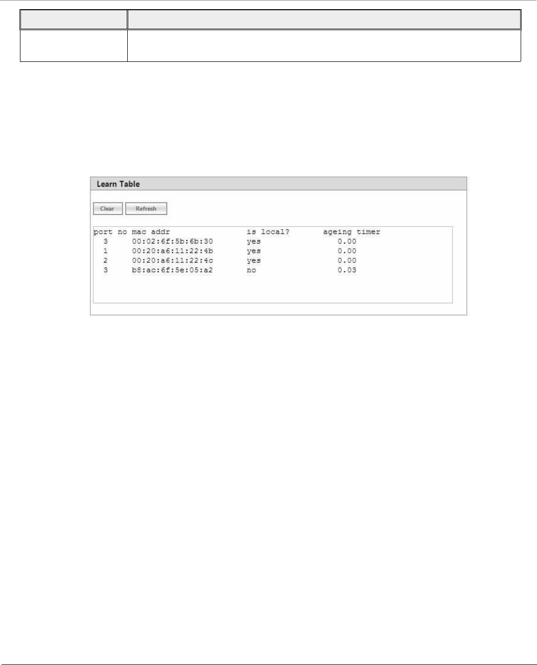
Monitor
Tsunami® 800 & 8000 Series - Software Management Guide 243
To view updated Bridge statistics, click Refresh.
To clear the Bridge statistics, click Clear.
7.5.2 Learn Table
Learn Table allows you to view all the MAC addresses that the device has learnt on all of its interfaces.
To view Learn Table statistics, navigate to MONITOR > Bridge > Learn Table. The Learn Table screen appears.
Figure 7-22 Learn Table
The Learn Table displays the MAC address of the learnt device, the bridge port number, aging timer for each device learnt on
an interface, and the local (DUT's local interfaces)/remote (learned entries through bridging) status of the learnt device.
To view updated learn table statistics, click Refresh.
To clear learn table statistics, click Clear.
7.6 Network Layer
7.6.1 Routing Table
Routing table displays all the active routes of the network. These can be either static or dynamic (obtained through RIP). For
every route created in the network, the details of that particular link or route will get updated in this table.
To view the Routing Table, navigate to MONITOR > Network Layer > Routing Table. The Routing Table screen appears:
Out Errors Represents the number of outbound packets that could not be transmitted because of
errors.
Parameter Description

Monitor
Tsunami® 800 & 8000 Series - Software Management Guide 244
Figure 7-23 Routing Table
7.6.2 IP ARP
Address Resolution Protocol (ARP) is a protocol for mapping an Internet Protocol address (IP address) to a physical address on
the network. The IP ARP table is used to maintain a correlation between each IP address and its corresponding MAC address.
ARP provides the protocol rules for making this correlation and providing address conversion in both directions.
To view IP Address Resolution Protocol (ARP) statistics, navigate to MONITOR > Network Layer > IP ARP. The IP ARP Table
screen appears.
Figure 7-24 IP ARP Table
The IP ARP Table contains the following information:
Index: Represents the interface type.
MAC Address: Represents the MAC address of a node on the network.
Net Address: This parameter represents the corresponding IP address of a node on the network.
Type: This parameter represents the type of mapping, that is, Dynamic or Static.
To view updated IP ARP entries, click Refresh.
To clear the IP ARP entries, click Clear.
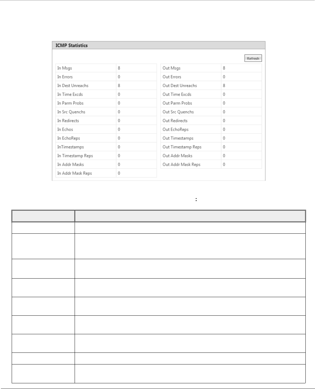
Monitor
Tsunami® 800 & 8000 Series - Software Management Guide 245
7.6.3 ICMP Statistics
The ICMP Statistics attributes enable you to monitor the message traffic that is received and transmitted by the device.
To view ICMP statistics, navigate to MONITOR > Network Layer > ICMP Statistics. The ICMP Statistics screen appears.
Figure 7-25 ICMP Statistics
The following table lists the ICMP Statistics parameters and their description
Parameter Description
In Msgs or Out Msgs Represents the number of ICMP messages that are received/transmitted by the device.
In Errors or Out Errors Represents the number of ICMP messages that are received/transmitted by the device but
determined as having ICMP-specific errors such as Bad ICMP checksums, bad length and
so on.
In Dest Unreachs or
Out Dest Unreachs
Represents the number of ICMP destination unreachable messages that are
received/transmitted by the device.
In Time Excds or Out
Time Excds
Represents the number of ICMP time exceeded messages that are received/transmitted by
the device.
In Parm Probs or Out
Parm Probs
Represents the number of ICMP parameter problem messages that are
received/transmitted by the device.
In Srec Quenchs or
Out Srec Quenchs
Represents the number of ICMP source quench messages that are received/transmitted by
the device.
In Redirects or Out
Redirects
Represents the rate at which the ICMP redirect messages are received/transmitted by the
device.
In Echos Represents the rate at which the ICMP echo messages are received.
In EchoReps or Out
EchoReps
Represents the rate at which the ICMP echo reply messages are received/transmitted by
the device.
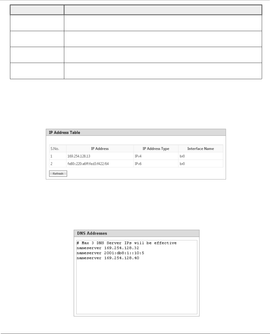
Monitor
Tsunami® 800 & 8000 Series - Software Management Guide 246
To view updated ICMP Statistics, click Refresh.
7.6.4 IP Address Table
The IP Address Table shows all IP addresses of the device. The IP Address Table screen contains IP addresses of the interface.
To view table, navigate to MONITOR > Network Layer > IP Address Table. The IP Address Table screen appears.
Figure 7-26 IP Address Table
7.6.5 DNS Addresses
It shows DNS Addresses currently active on the device. To view DNS addresses, navigate to MONITOR > Network Layer >
DNS Addresses. The DNS Addresses screen appears.
Figure 7-27 DNS Addresses
In Timestamps or Out
Timestamps
Represents the rate at which the ICMP timestamp (request) messages are
received/transmitted by the device.
In Timestamps Reps or
Out Timestamps Reps
Represents the rate at which the ICMP timestamp reply messages are received/transmitted
by the device.
In Addr Masks or Out
Addr Masks
Represents the number of ICMP address mask request messages that are
received/transmitted by the device.
In Addr Mask Reps or
Out Addr Mask Reps
Represents the number of ICMP address mask reply messages that are
received/transmitted by the device.
Parameter Description
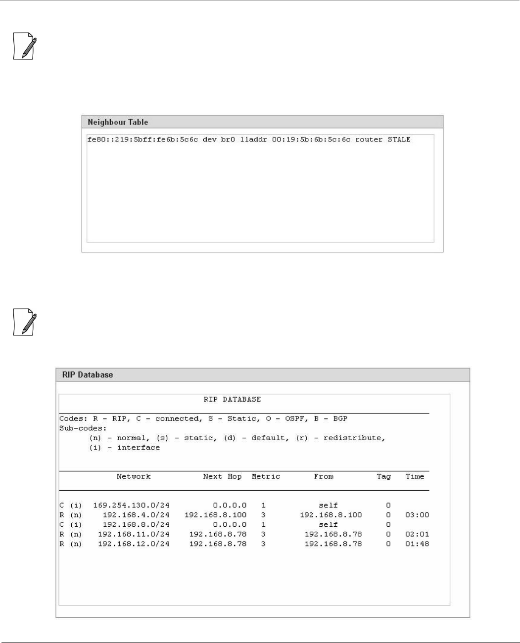
Monitor
Tsunami® 800 & 8000 Series - Software Management Guide 247
7.6.6 Neighbour Table
: This parameter is applicable only in IPv4 and IPv6 mode, not in IPv4 only mode.
The Neighbour Table contains a list of neighbouring routers and information about them. To view Neighbour Table, navigate
to MONITOR > Network Layer > Neighbour Table. The Neighbour table screen appears.
Figure 7-28 Neighbour Table
7.6.7 RIP Database
: Applicable only in routing mode.
The RIP Database screen contains routes (Routing Information Protocol updates) learnt from other routers.
Figure 7-29 RIP Database
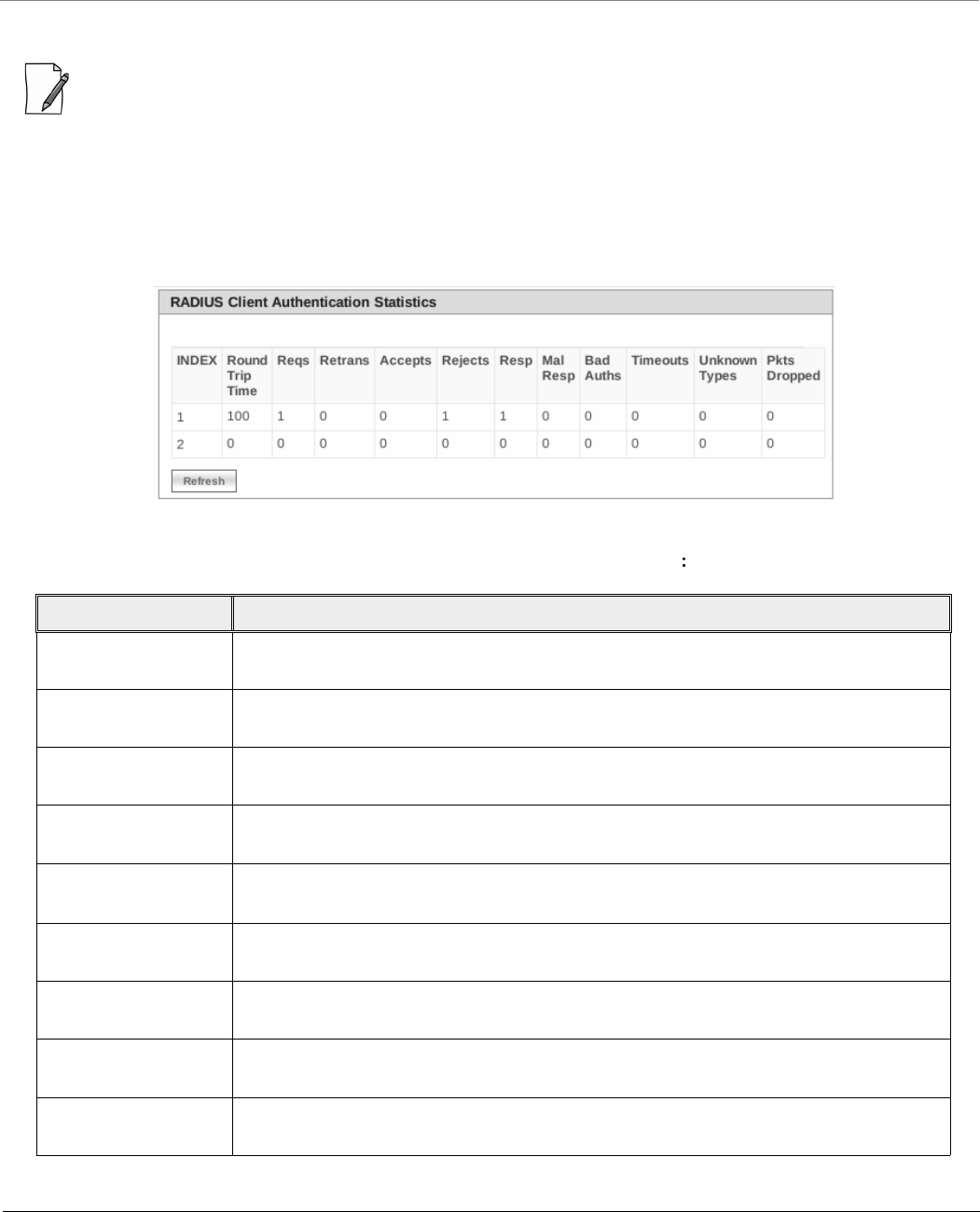
Monitor
Tsunami® 800 & 8000 Series - Software Management Guide 248
7.7 RADIUS (BSU or End Point A only)
: RADIUS is applicable only to a BSU or an End Point A device.
7.7.1 Authentication Statistics
Authentication Statistics provides information on RADIUS Authentication for both the primary and backup servers for each
RADIUS server profile.
To view Authentication statistics, navigate to MONITOR > RADIUS > Authentication Statistics. The RADIUS Client
Authentication Statistics screen appears:
Figure 7-30 Radius Client Authentication Statistics
The following table lists the Authentication Statistics parameters and their description
Parameter Description
Round Trip Time Represents the round trip time for messages exchanged between RADIUS client and
authentication server since the client startup.
Reqs Represents the number of RADIUS access request messages transmitted from the RADIUS
client to the authentication server since client startup.
RTMS This parameter represents the number of times the RADIUS access requests are being
transmitted to the server from the device since the client startup.
Accepts Represents the number of RADIUS access accept messages received by the device since
client startup.
Rejects Represents the number of RADIUS access reject messages received by the device since
client startup.
Resp Represents the number of RADIUS response packets received by the device since client
startup.
Mal Resp Represents the number of malformed RADIUS access response messages received by the
device since client startup.
Bad Auths Represents the number of malformed RADIUS access response messages containing invalid
authenticators received by the device since client startup.
Time Outs Represents the total number of timeouts for RADIUS access request messages since client
startup.
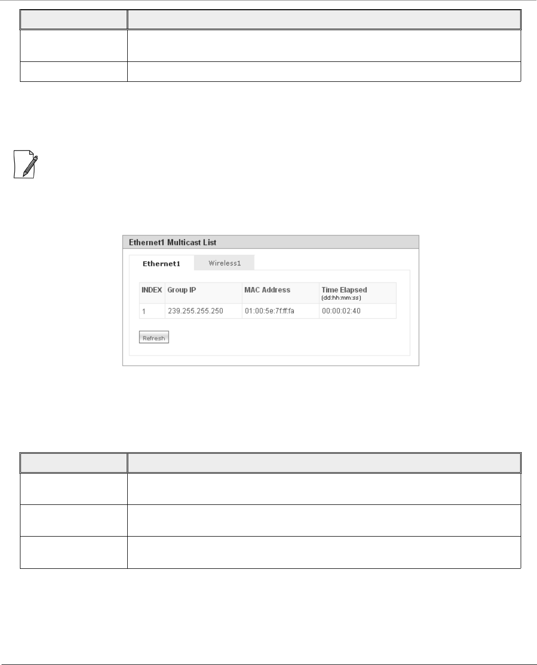
Monitor
Tsunami® 800 & 8000 Series - Software Management Guide 249
To view updated RADIUS Client Authentication statistics, click Refresh.
7.8 IGMP
: Applicable in Bridge mode only.
To view IGMP statistics, navigate to MONITOR > IGMP > IGMP Snooping Stats. The Ethernet or Wireless Multicast List
screen appears:
Figure 7-31 Ethernet1 Multicast List
7.8.1 Ethernet or Wireless Multicast List
The Multicast List table contains the IGMP Multicast IP and Multicast MAC address details for the Ethernet or Wireless
interfaces. The following table lists the parameters and their description.
To view updated IGMP statistics, click Refresh.
7.8.2 Router Port List
The Router Port List displays the list of ports on which multicast routers are attached.
To view Router Port List, navigate to MONITOR > IGMP > Router Port List. The Router Port List screen appears:
UnKnown Types This parameter specifies the number of messages with unknown RADIUS message code
since client startup.
Packets Dropped Represents the number of RADIUS packets dropped by the device.
Parameter Description
Group IP Represents the IP address of the multicast group for Ethernet or Wireless interface learned
by IGMP snooping.
MAC Address Represents the MAC address of the multicast group for Ethernet or Wireless interface
learned by IGMP snooping.
Time Elapsed Represents the time elapsed since the multicast entry has been created for the Ethernet or
Wireless interface.
Parameter Description
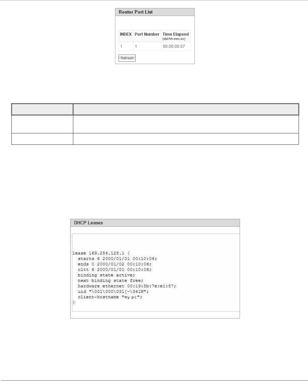
Monitor
Tsunami® 800 & 8000 Series - Software Management Guide 250
Figure 7-32 Router Port List
The following table lists the parameters and their description.
To view updated Router Port list, click Refresh.
7.9 DHCP
DHCP Leases file stores the DHCP client database that the DHCP Server has served. The information stored includes the
duration of the lease, for which the IP address has been assigned, the start and end dates for the lease, and the MAC address
of the network interface card of the DHCP client.
To view DHCP Leases, navigate to MONITOR > DHCP > Leases.
Figure 7-33 DHCP Leases
Parameter Description
Port Number Represents the port number on which multicast router is attached (on which IGMP Query
has been received).
Time Elapsed Represents the time elapsed since the port is marked as the router port.
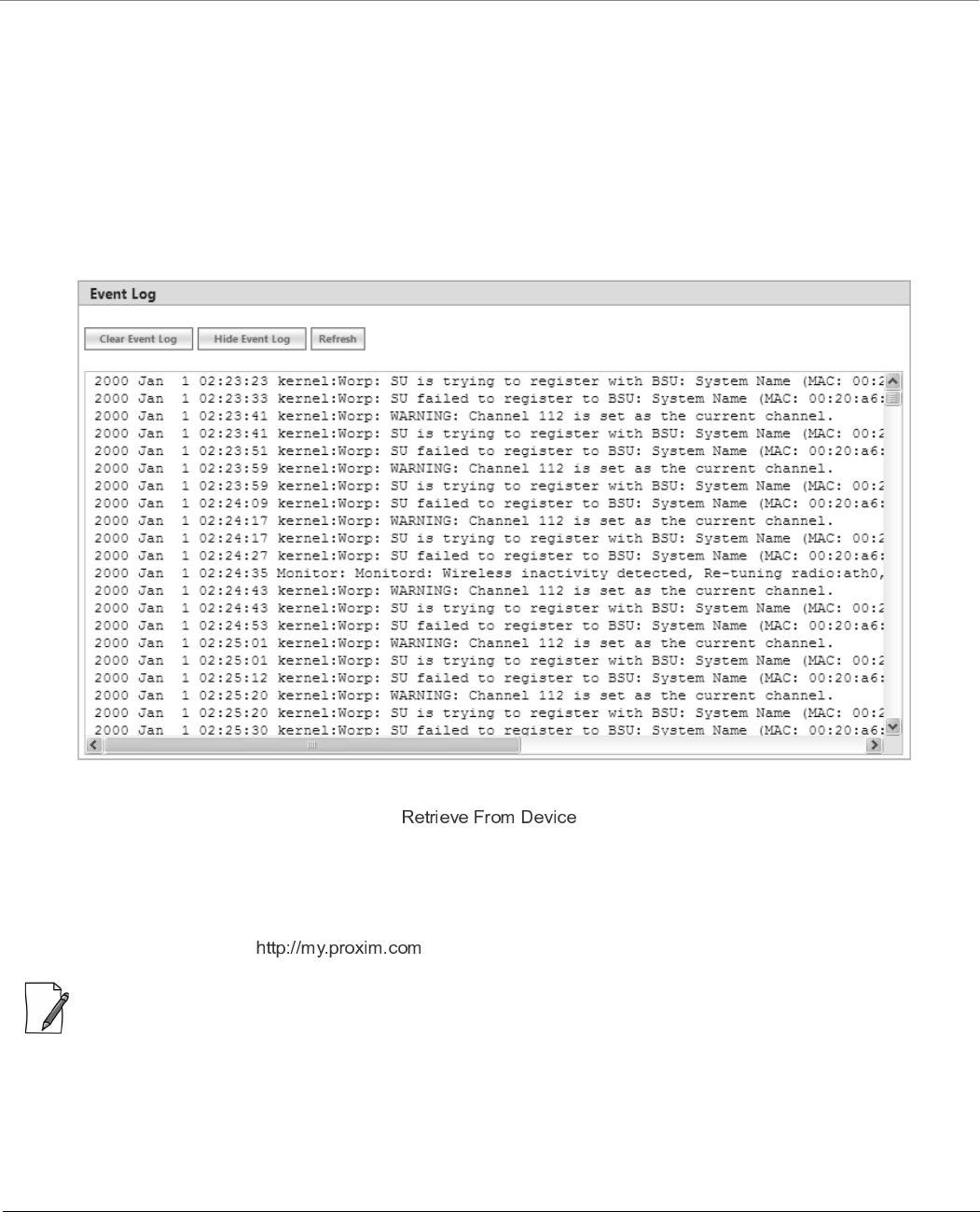
Monitor
Tsunami® 800 & 8000 Series - Software Management Guide 251
7.10 Logs
7.10.1 Event Log
Event Log file keeps track of events that occur during the operation of the device. It displays the event occurring time, event
type, and the name of the error or the error message. Based on the priority (the log priority is set under MANAGEMENT >
Services > Logs), the event details are logged and can be used for any future reference or troubleshooting.
7.10.1.1 View Event Log
To view the event log messages, navigate to MONITOR > Logs > Event Log. The following Event Log screen appears:
Figure 7-34 Event Log Messages
To retrieve the event log file from the device, see .
The maximum size of the event log file is 65 KB. If the file size exceeds 65 KB, then all the log messages are moved to a
backup file and only the recent 100 lines are displayed in the log file. When the size of the log file exceeds again then it
overwrites the backup file.
Backup files can be retrieved by using ‘retrieve’ CLI command. For more details, see Tsunami 800 and 8000 Series
Reference guide available at .
: Log messages can be stored in the log file approximately up to 6 days with logging interval of 5 minutes.
7.10.1.2 Hide Event Log
To hide the event log messages, click Hide Event Log.
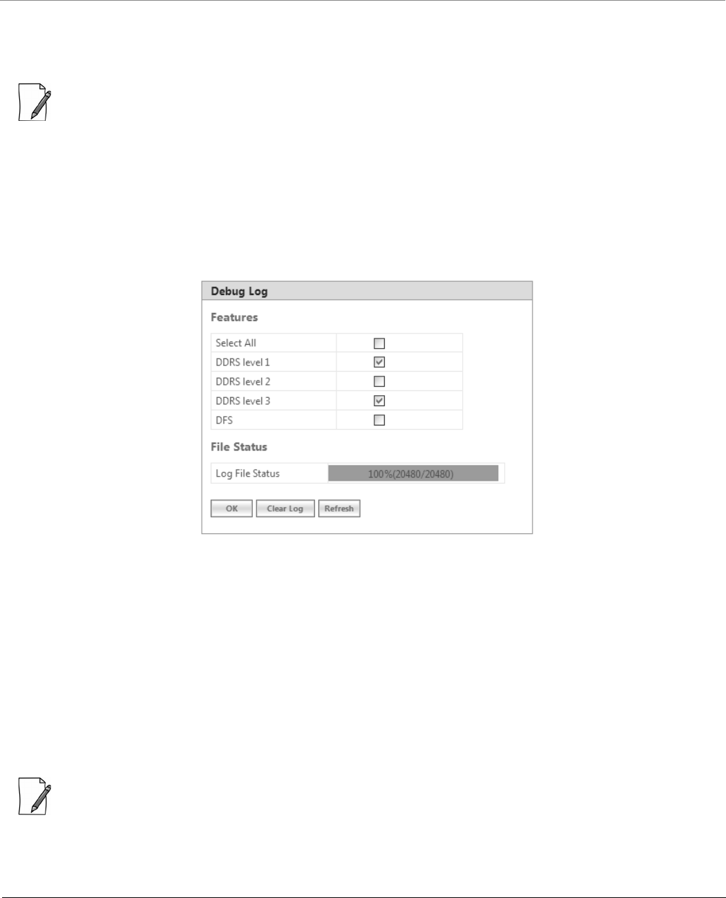
Monitor
Tsunami® 800 & 8000 Series - Software Management Guide 252
7.10.1.3 Clear Event Log
To clear the event log messages, click Clear Event Log. The messages are cleared and moved to the backup file leaving the
event log file empty. An event is generated on clearing the event log messages.
: The current and the backed up event logs are stored in the flash memory and can be retrieved even after device
reboot.
7.10.2 Debug Log
Debug Log helps you to debug issues related to important features of the device. Currently, this feature supports only DDRS
and DFS. This feature helps the engineering team to get valuable information from the field to analyze the issues and provide
faster solution. This feature should be used only in consultation with the Proxim Customer Support team. Once logging is
enabled, the Debug Log file can be retrieved via HTTP or TFTP.
To enable Debug Log, navigate to MONITOR > Logs > Debug Log. The Debug Log screen appears:
Figure 7-35 Debug Log
Features: Select the appropriate features to be logged. The available features are Select All, DDRS Level 1, DDRS Level 2, DDRS
Level 3 and DFS.
File Status: This parameter displays the current size of the Debug Log file.
After selecting the DDRS level, click OK.
To delete the Debug Log, click Clear Log.
To get the updated status of the Debug Log File, Click Refresh.
7.10.3 Temperature Log
: Temperature Log is not applicable to MP-8150-CPE, MP-8160-CPE, MP-825-CPE-50, MP-820-BSU-100,
MP-820-SUA-50+, MP-825-SUR-50+, QB-825-EPR/LNK-50, QB-825-EPR/LNK-50+ and QB-8150-LNK-12/50 devices.
Temperature Log feature is used to log the internal temperature of the device for the configured temperature logging interval
(By default, it is 5 minutes). It also generates a trap and an event message when the internal temperature of the device
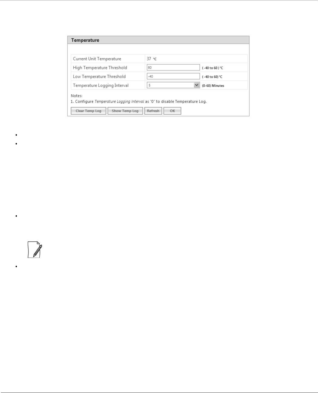
Monitor
Tsunami® 800 & 8000 Series - Software Management Guide 253
reaches or exceeds the configured threshold range. The device issues a warning trap when the temperature is 5º Celsius less
than the configured threshold range.
To access this feature, navigate to MONITOR > Logs > Temperature Log. The following Temperature screen appears:
Figure 7-36 Temperature Log
Current Unit Temperature: Displays the current internal temperature of the device in Celsius.
High and Low Temperature Threshold:
– Configure the high temperature threshold ranging from -40ºC to 60ºC. By default, it is set to 60ºC.
– Configure the low temperature threshold ranging from -40ºC to 60ºC. By default, it is set to -40ºC.
– When the current internal temperature of the device reaches or exceeds this threshold range, then a trap and event
message is generated for every one hour (as long as it stays in the same state). If the temperature of the device
further changes, then the device will immediately generates another trap and an event message.
– For example, lets say the configured threshold range is -30(low) to 40 (high). If the device temperature reaches 50
then a trap and event message is generated for every one hour till it remains at 50. So, when the temperature
increases to 51 then it will immediately generate another trap and an event message.
Temperature Logging Interval: A logging interval from 1 to 60 minutes with 5 minute increment can be selected.
For example, if you configure logging interval as 10 minutes then the device temperature is logged for every 10
minutes.
: If the logging interval is configured ‘0’, then the temperature log feature will be disabled.
After configuring the parameters, click OK followed by COMMIT.
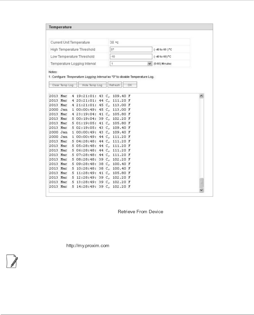
Monitor
Tsunami® 800 & 8000 Series - Software Management Guide 254
7.10.3.1 View Temperature Log
To view the temperature Log, click Show Temp Log.
Figure 7-37 View Temperature Log
To retrieve the temperature log file from the device, see .
The maximum size of the temperature log file is 65 KB. If the file size exceeds 65 KB, then all the log messages are moved to
a backup file and only the recent 100 lines are displayed in the log file. When the size of the log file exceeds again then it
overwrites the backup file.
Backup files can be retrieved by using ‘retrieve’ CLI command. For more details, see Tsunami 800 and 8000 Series
Reference guide available at .
: Log messages can be stored in the log file approximately up to 6 days with logging interval of 5 minutes.
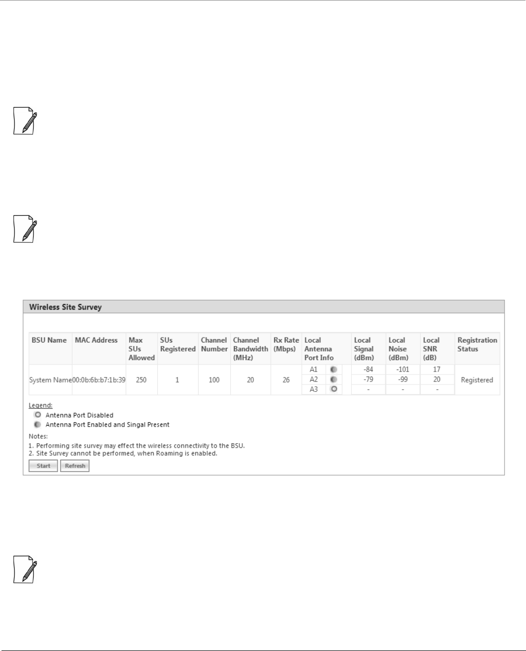
Monitor
Tsunami® 800 & 8000 Series - Software Management Guide 255
7.10.3.2 Hide Temperature Log
To hide the temperature log messages, click Hide Temp Log.
7.10.3.3 Clear Temperature Log
To clear the temperature log messages, click Clear Temp Log. The messages are cleared and moved to the backup file leaving
the temperature log file empty. An event is generated on clearing the temperature log messages.
: The current and the backed up temperature logs are stored in the flash memory and can be retrieved even after device
reboot.
7.11 Tools
7.11.1 Wireless Site Survey
: Applicable only to a device in SU or End Point B mode.
Wireless Site Survey is done by the SU or End Point B only. This feature scans all the available channels according to the
current Channel Bandwidth, and collects information about all BSUs or Endpoint A configured with the same network name
as SUs or End Point B.
Figure 7-38 Wireless Site Survey - SU Mode
To initialize the survey process, click Start. This process list the details of all the available BSUs or End Point A. To stop the site
survey process, click Stop.
During the scan process, click Refresh to view the latest discovered BSU/End Point A.
: Site Survey cannot be performed, when Roaming is enabled.
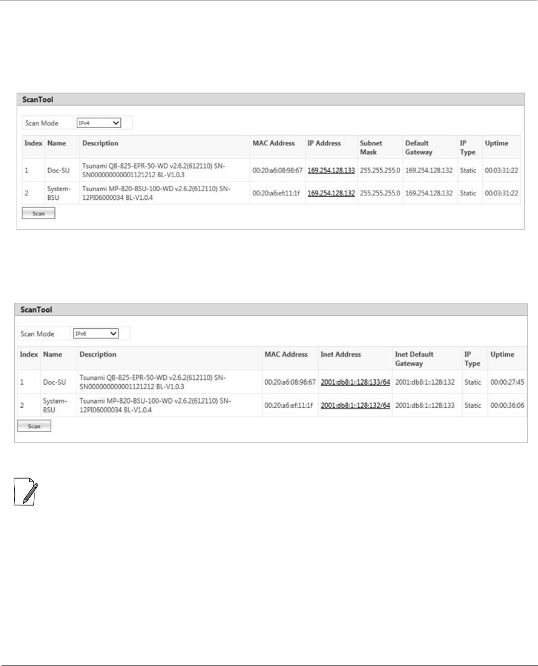
Monitor
Tsunami® 800 & 8000 Series - Software Management Guide 256
7.11.2 Scan Tool
With Scan Tool, you can scan all the Proxim devices available on the network.
To scan the devices, navigate to MONITOR > Tools > Scan Tool. The Scan Tool screen appears. In the Scan Tool screen,
select Scan Mode as IPv4. Click Scan to scan and refresh the devices on the network. The scanned devices are displayed as
shown below:
Figure 7-39 An Example - Scanned Devices (IPv4)
In the Scan Tool screen, select Scan Mode as IPv6 to scan the 82x devices with IPv6 mode. Click Scan to scan and refresh
the devices on the network. The scanned 82x devices are displayed as shown below:
Figure 7-40 An Example - Scanned Devices (IPv6)
: ScanTool IPv6 support is applicable only for the 82x devices with IPv6 mode.
7.11.3 sFlow®
Proxim’s point-to-multipoint and point-to-point devices support sFlow® technology, developed by InMon Corporation. The
sFlow® technology provides the ability to measure network traffic on all interfaces simultaneously by collecting, storing, and
analyzing traffic data.
Depicted below is the sFlow architecture that consists of a sFlow Agent and a sFlow Receiver.
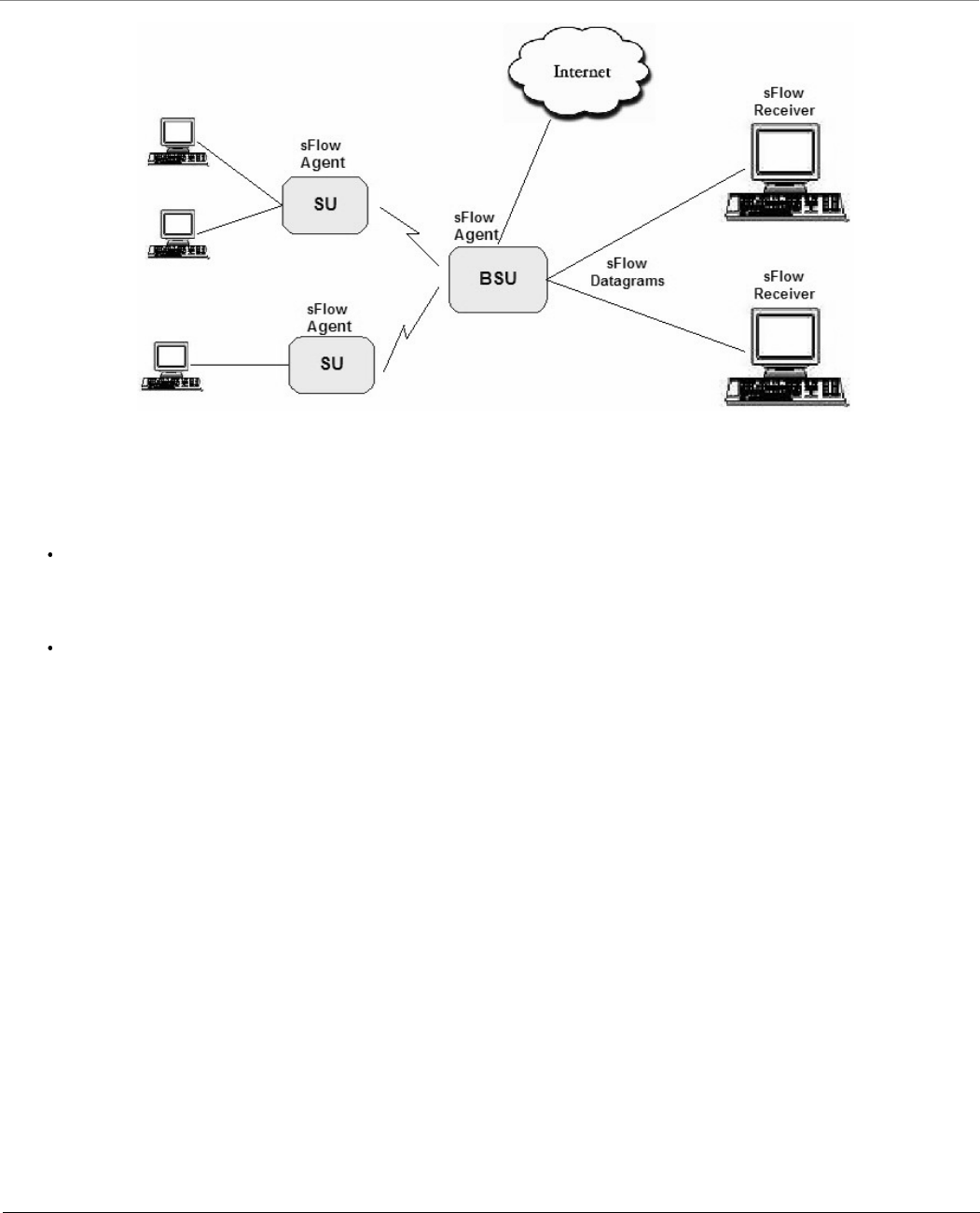
Monitor
Tsunami® 800 & 8000 Series - Software Management Guide 257
Figure 7-41 sFlow Architecture - An Example with a BSU and SUs
The sFlow Agent, which is running on devices, captures traffic information received on all the Ethernet interfaces, and sends
sampled packets to the sFlow Receiver for analysis.
The sampling mechanism used to sample data are as follows:
Packet Flow Sampling: In this sampling, the data packets received on the Ethernet interface of the device are
sampled based on a counter. With each packet received, the counter is decremented. When the counter reaches zero,
the packet is packaged and sent to the sFlow Receiver for analysis. These packets are referred to as Packet Flow
Samples.
Counter Polling Sampling: In this sampling, the sFlow Agent sends counters periodically to the sFlow Receiver based
on the set polling interval. If polling interval is set to 5 seconds then the sFlow Agent sends counters to sFlow Receiver
every 5 seconds. These packets are referred to as Counter Polling Samples.
The Packet Flow Samples and Counter Polling Samples are collectively sent to the sFlow Receiver as sFlow Datagrams. It is
possible to enable either or both types of sampling.
sFlow Sampling effects the system performance and hence care must be taken in configuring the sFlow parameters.
To configure sFlow, navigate to MONITOR > Tools > sFlow. The following sFlow® screen appears:
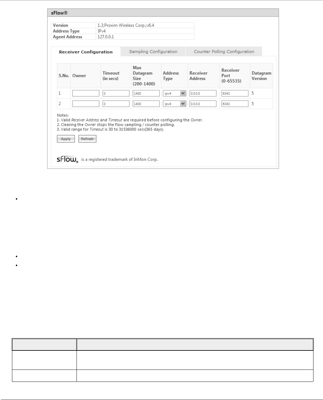
Monitor
Tsunami® 800 & 8000 Series - Software Management Guide 258
Figure 7-42 sFLOW
This screen displays the following information about the sFlow Agent:
Version: The version displayed is 1.3;Proxim Wireless Corp.; v6.4. The version comprises the following information:
1. sFlow MIB Version: Indicates the agent’s MIB version. The MIB specifies how the agent extracts and bundles
sampled data, and the sFlow receiver must support the agent’s MIB. The sFlow MIB version is 1.3. so the sFlow
Receiver’s version must also be at least 1.3.
2. Organization: Specifies the organization implementing sFlow Agent functionality on the device, that is, Proxim
Wireless Corp.
3. Revision: Specifies the sFlow Agent version, that is, v6.4.
Address Type: Specifies the protocol version for IP addresses.
Agent Address: Specifies the sFlow Agent’s IP address.
7.11.3.1 sFlow Receiver Configuration
The Receiver Configuration page allows you to configure sFlow Receiver(s), which receives samples from all agents on the
network, combines and analyzes the samples to produce a report of network activity.
To configure sFlow Receiver, navigate to MONITOR > Tools > sFlow and select Receiver Configuration tab.
Given below is the table which explains sFlow parameters and the method to configure the configurable parameter(s):
Parameter Description
S.No. Represents the Receiver index number. Please note that the number of indexes depends
on the Ethernet interfaces your device supports.
Owner Enter a string, which uniquely identifies the sFlow Receiver.

Monitor
Tsunami® 800 & 8000 Series - Software Management Guide 259
Click Apply, to save the sFlow Receiver configuration parameters.
Once the Receiver configurations are done, either Packet Flow sampling or Counter Polling Sampling or both can be started.
:
Enabling sampling effects the system performance and hence care should be taken in setting the right values for
Timeout and Max Datagram Size.
When the Owner string is cleared, the Flow Sampling and Counter Polling stops.
7.11.3.2 Sampling Configuration
To configure and start packet flow sampling, do the following:
1. Navigate to MONITOR > Tools > sFlow and select Sampling Configuration tab.
Time Out Enter a value ranging from 30 to 31536000 seconds (365 days) in the Time Out box.
The sFlow Agent sends sampled packets to the specified sFlow Receiver till it reaches zero.
At zero, all the Receiver parameters are set to default values.
Max Datagram Size Enter the maximum size of a sFlow datagram (in bytes), which the Receiver can receive, in
the Max Datagram Size box. By default, the maximum datagram size is set to 1400
bytes. It can range from 200 to 1400 bytes.
Address Type The address type supported by sFlow Receiver is ipv4, which is by default selected.
: Only IPv4 is currently supported.
Receiver Address Enter the sFlow Receiver’s IP address in the Receiver Address box.
Receiver Port By default, the sFlow Receiver listens to the sFlow datagrams on 6343 port. To change the
port, enter a valid port ranging from 0 to 65535 in the Receiver Port box.
Datagram Version The sFlow datagram version used is 5.
Parameter Description
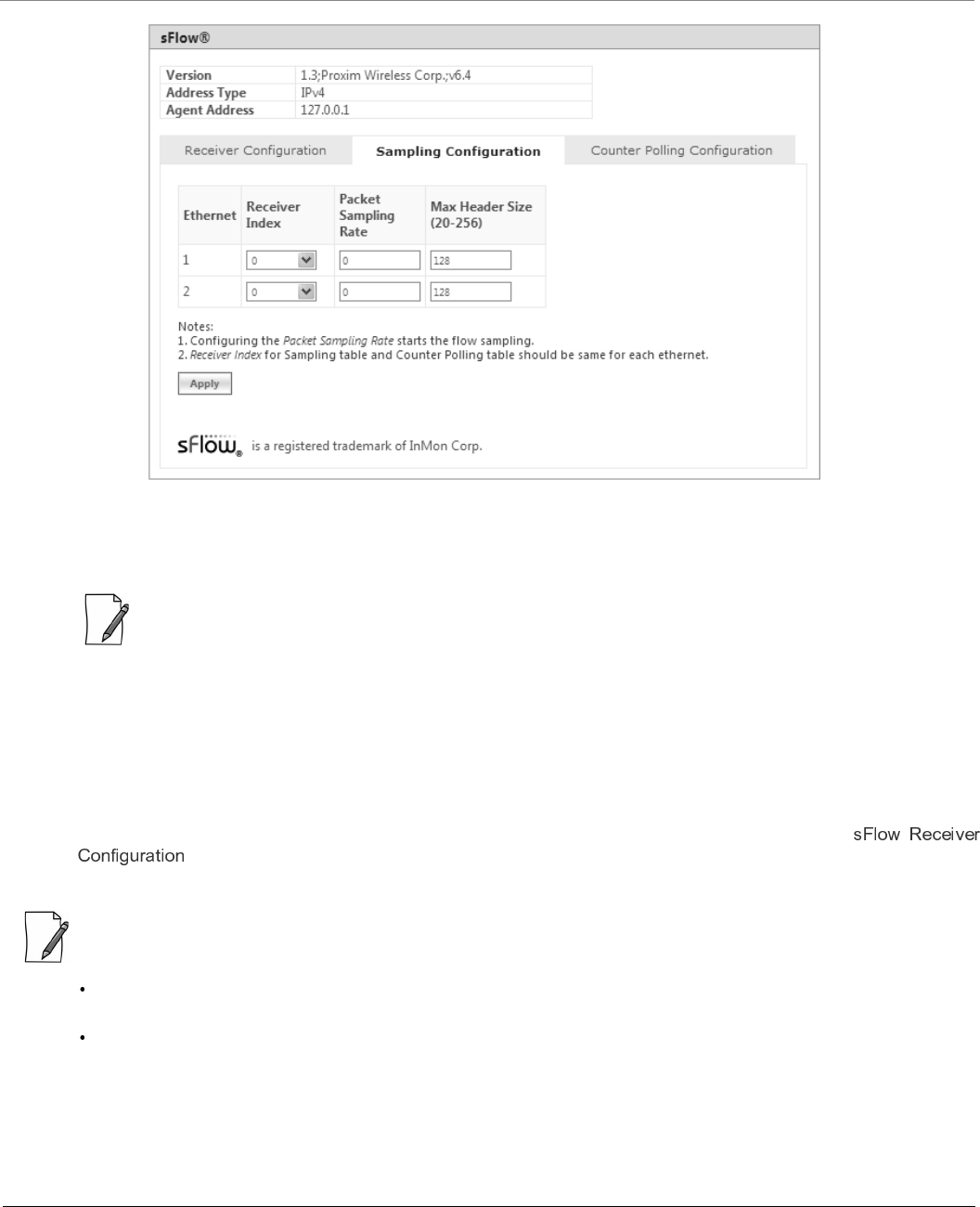
Monitor
Tsunami® 800 & 8000 Series - Software Management Guide 260
Figure 7-43 sFlow Sampling Configuration
2. From the Receiver Index drop-down box, select the receiver index number associated with the sFlow Receiver to
which the sFlow Agent should send the sFlow Datagrams.
: If device has two Ethernet interfaces, then configure different Receiver indexes for each of the interface.
3. Type a value in the Packet Sampling Rate box. This value determines the number of packets the sFlow Agent
samples from the total number of packets passing through the Ethernet interface of the device.
4. Type a value in the Maximum Header Size box, to set the amount of data (in bytes) to be included in the sFlow
datagram. The sFlow Agent samples the specified number of bytes. For example, if you set the Maximum Header Size
to 100, the sFlow Agent places the first 100 bytes of every sampled frame in the datagram. The value should match
the size of the frame and packet header so that the entire header is forwarded. The default size is 128 bytes. The
header size can range from 20 to 256 bytes.
5. Next, click Apply to start packet flow sampling. Once it starts, the Time Out parameter (see
) keeps decrementing till it reaches a zero value. On reaching zero, the corresponding Receiver and
Sampling values are set to default values.
:
Enabling sFlow packet sampling effects the system performance, and hence care must be taken when choosing the
right value for Packet Sampling Rate and Maximum Header Size.
Receiver Index for packet Sampling table and Counter Polling table should be same for each Ethernet interface.
7.11.3.3 Counter Polling Configuration
To configure and start Counter Polling sampling, do the following:
1. Navigate to MONITOR > Tools > sFlow and select Counter Polling Configuration tab.
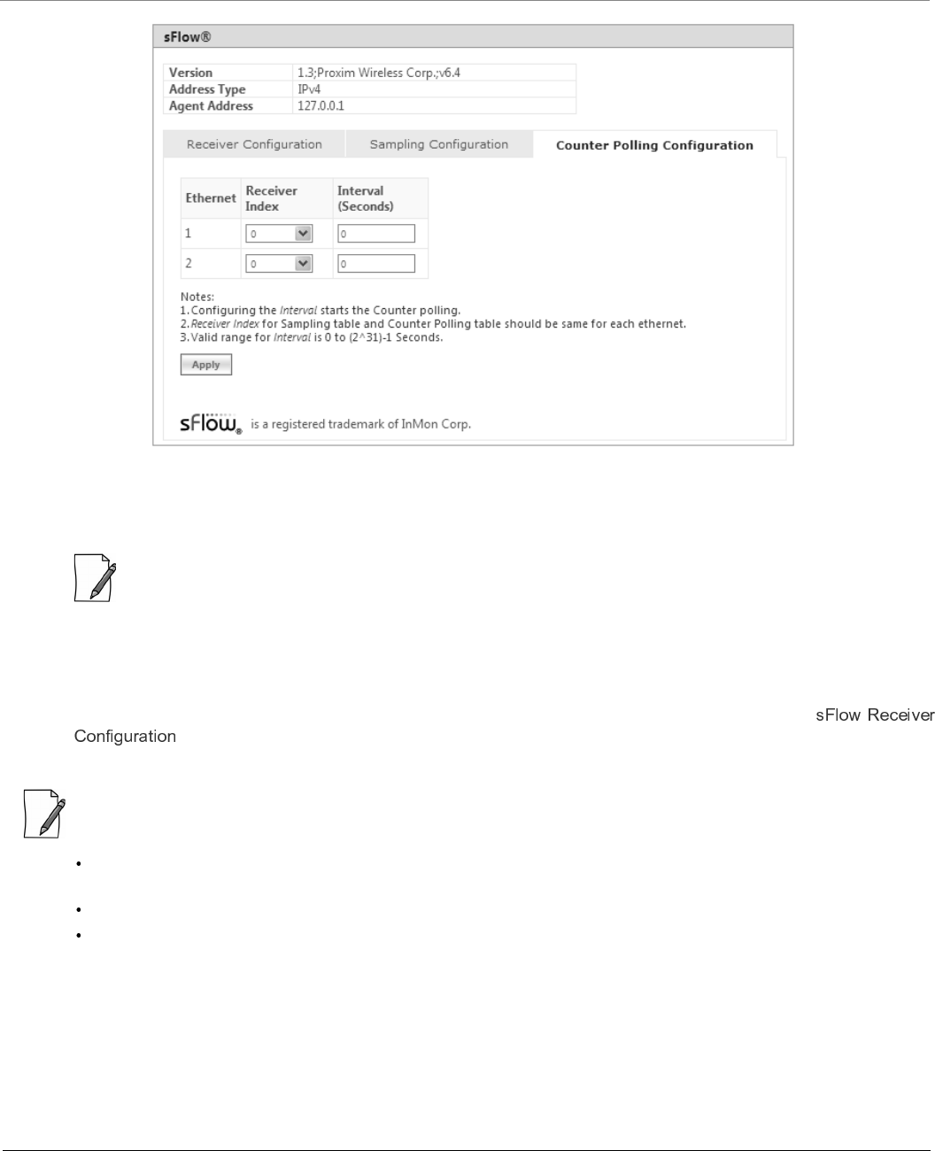
Monitor
Tsunami® 800 & 8000 Series - Software Management Guide 261
Figure 7-44 Counter Polling Configuration
2. From the Receiver Index drop-down box, choose the receiver index number associated with the sFlow Receiver to
which the sFlow Agent sends the counters.
: If Packet Flow Sampling is already configured and running, then you should configure the Receiver index same
as configured in the Packet Flow Sampling for each Ethernet interface.
3. Set the polling interval by typing a value in the Interval box. Lets say, the polling interval is set to 30 seconds. So for
every 30 seconds, the counters are collected and send to the sFlow Receiver. The valid range for polling interval is 0 to
231 - 1 seconds.
4. Next, click Apply to start Counter Polling Sampling. Once it starts, the Time Out parameter (see
) keeps decrementing till it reaches a zero value. On reaching zero, the corresponding Receiver and
Counter Polling values are set to default values.
Enabling sFlow counter sampling effects the system performance, and hence care must be taken when choosing the
right value sampling interval.
Receiver Index for packet Sampling table and Counter Polling table should be same for each Ethernet interface.
If a sampling starts and there is already another sampling running then we consider the time out value of the
current/already running sampling.
7.11.4 Console Commands
The Console Commands feature helps Proxim’s Technical Support team to debug field issues.
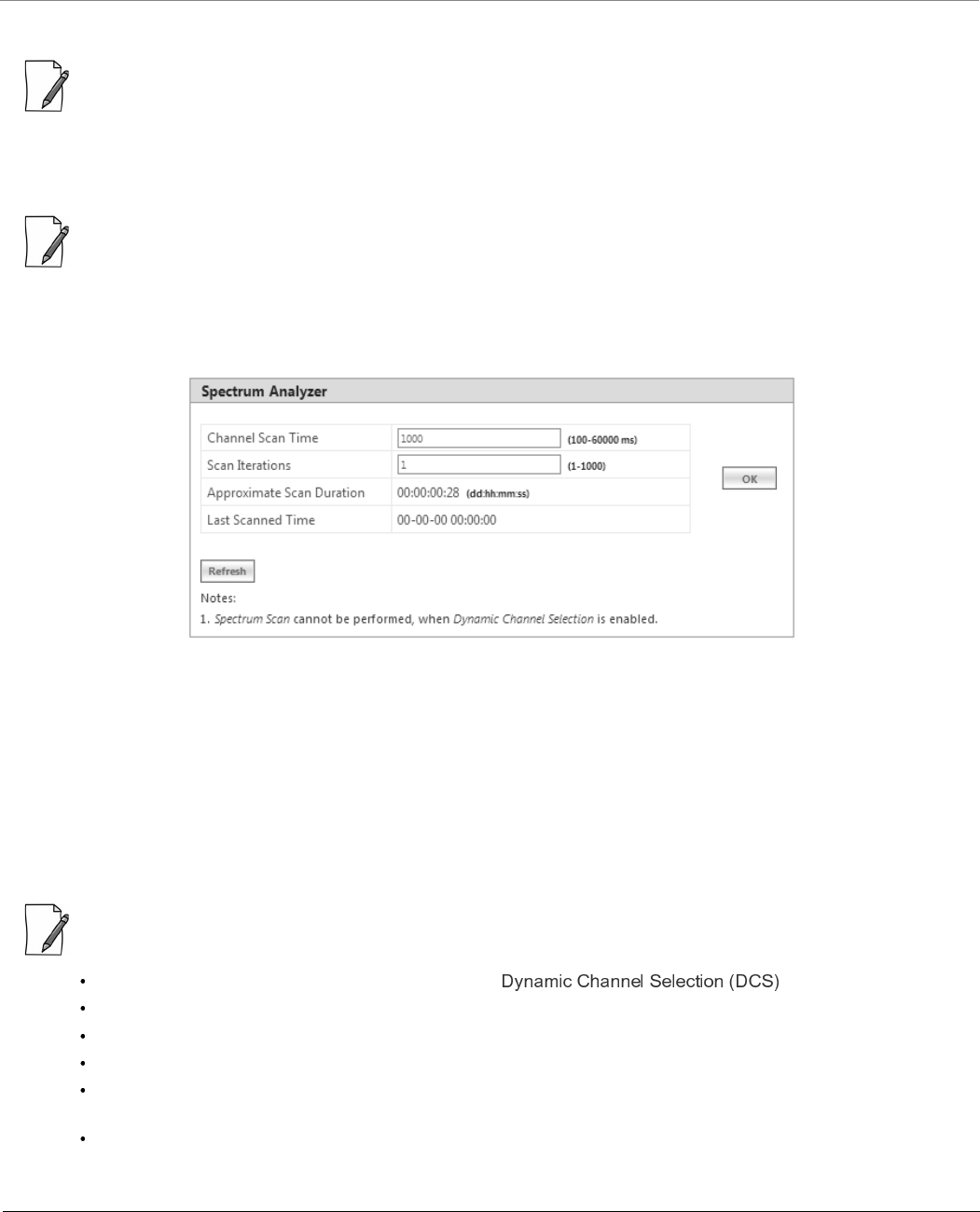
Monitor
Tsunami® 800 & 8000 Series - Software Management Guide 262
7.11.5 Spectrum Analyzer
: Spectrum Analyzer is not applicable to MP-8150-CPE and QB-8150-LNK-12/50 devices.
Spectrum Analyzer helps to analyze a spectrum for interference, and select a relatively low interference channel. This tool is
not a replacement for the commercial Spectrum Analyzers as this is only intended to help with channel selection and
diagnose performance issues.
: Only an administrator user can use Spectrum Analyzer to scan the spectrum. However, the Monitor user can view the
last scanned results.
To scan all the channels in the configured frequency domain, do the following:
1. Navigate to MONITOR > Tools > Spectrum Analyzer. The following Spectrum Analyzer screen appears:
Figure 7-45 An Example - Spectrum Analyzer
2. Channel Scan Time: Enter the time (ranging from 100 to 60000 milliseconds) to scan each channel. By default, the
scan time is set to 1000 milliseconds.
3. Scan Iterations: Enter a number (ranging from 1 to 1000) which represents the number of times the scan iterates. By
default, the scan iteration is set to 1.
4. After configuring the Channel Scan Time and Scan Iterations, click OK. Upon clicking OK, the Approximate Scan
Duration parameter displays the total time (dd:hh:mm:ss) required to complete the scan.
5. Last Scanned Time: Represents the time at which the last spectrum scan was done.
6. Next click Start, to start the scan. Click Stop to stop the scan or wait for completion of the scan.
:
Spectrum Analyzer scan cannot be performed when is enabled.
The total duration of scan depends on the number of channels available, channel scan time and scan iterations.
To reduce scan duration, configure the appropriate frequency filter lower and upper edges.
While scanning, Spectrum Analyzer does not consider channel offset.
The frequencies are scanned by 5MHz slice starting from the lower edge of the frequency filter, and displays the
results captured at that particular instance.
Spectrum Analyzer detects only 802.11 modulated signals.
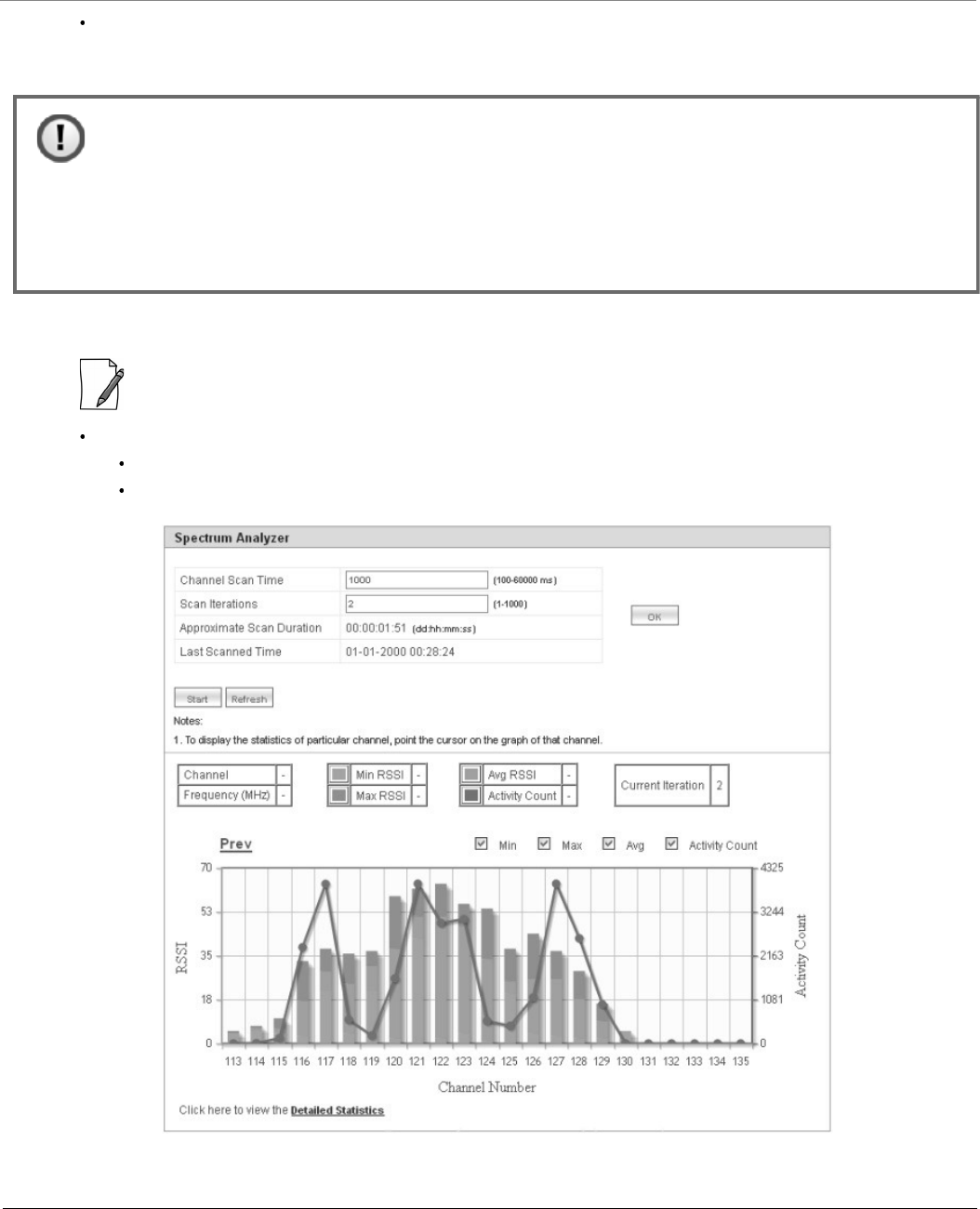
Monitor
Tsunami® 800 & 8000 Series - Software Management Guide 263
When working in a high interference network, ensure to run the spectrum analyzer with multiple iterations
(increase the Scan Time) to get accurate results.
7. The scanned results are displayed in the form of a graph as follows:
:
A minor variation in Spectrum Analyzer results can be expected due to the following reasons:
Satellite Density Configuration
A variation in the radio properties between various device models.
Figure 7-46 An Example - Scanned Results
:
• When the Spectrum Analyzer starts, the wireless link, if established, is terminated and re-established
after the scan is completed.
• As the wireless link is down during spectrum analysis, the remote device cannot be accessed. Hence, if
Spectrum Analyzer is started on a remote device, the results will not be available until spectrum scan is
completed and wireless link gets re-established.
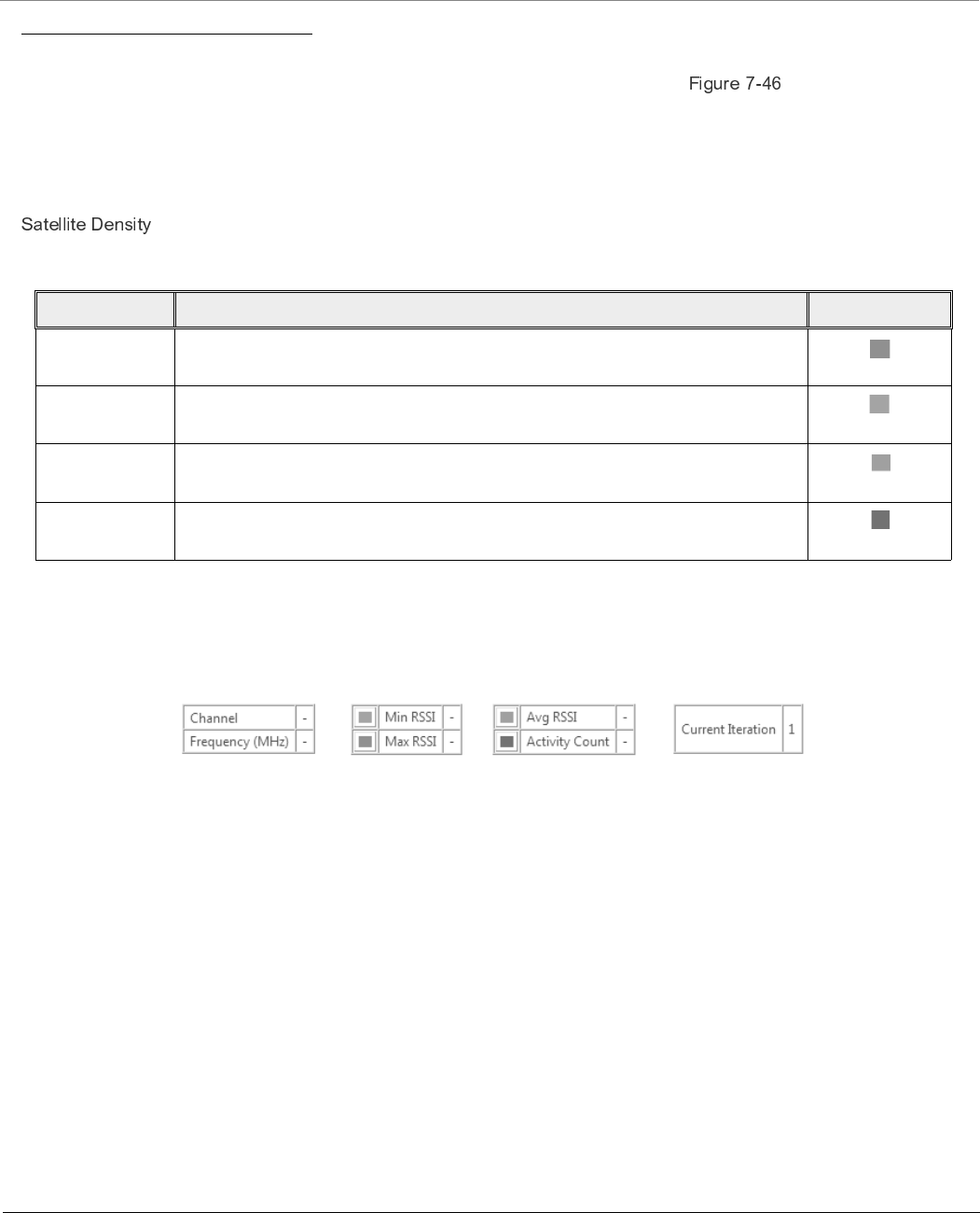
Monitor
Tsunami® 800 & 8000 Series - Software Management Guide 264
Graph Results Interpretation
Consider a network with a device operating on channel 122 with 20 MHz channel bandwidth. In the same vicinity, when we
run the Spectrum Analyzer on a Tsunami radio it will display the results as shown in . From the results, we see
interfering signals on channels 115 to 129. It also shows strong interfering signal on channels 120 to124 indicating the
presence of a device operating on channel 122, and moderate interfering signals on channels 115-119 and 125-129 (which
are side band signals from the same interference source).
We recommend to avoid using these channels while installing Tsunami products, otherwise radio will report huge PHY and
CRC errors. However, to make these channels usable and to ignore the low interference signals, we recommend configuring
on the devices.
By default, for each channel, the graph represents the following statistics:
Please note that the Current Iteration parameter helps to learn the current scan iteration. For example, if Scan Iteration is
configured as 2, and currently only one scan cycle is complete then Current Iteration parameter displays 1.
To view the statistics of a particular channel, point the cursor to that channel on the graph. The statistics is displayed as shown
below:
Figure 7-47 Channel Statistics
It is also possible to view only the selected statistics on the graph. For example, to view only Minimum and Maximum RSSI on
the graph, uncheck the box against Activity Count and Avg on the top of the graph.
Parameter Description Legend
Maximum RSSI Represents the maximum RSSI of all the signals received during the scan on a
given channel.
Minimum RSSI Represents the minimum RSSI of all the signals received during the scan on a
given channel.
Average RSSI Represents the average RSSI of all the signals received during the scan on a
given channel.
Activity Count Represents the total wireless activities (including OFDM Signal and Errors)
during the scan on a given channel.
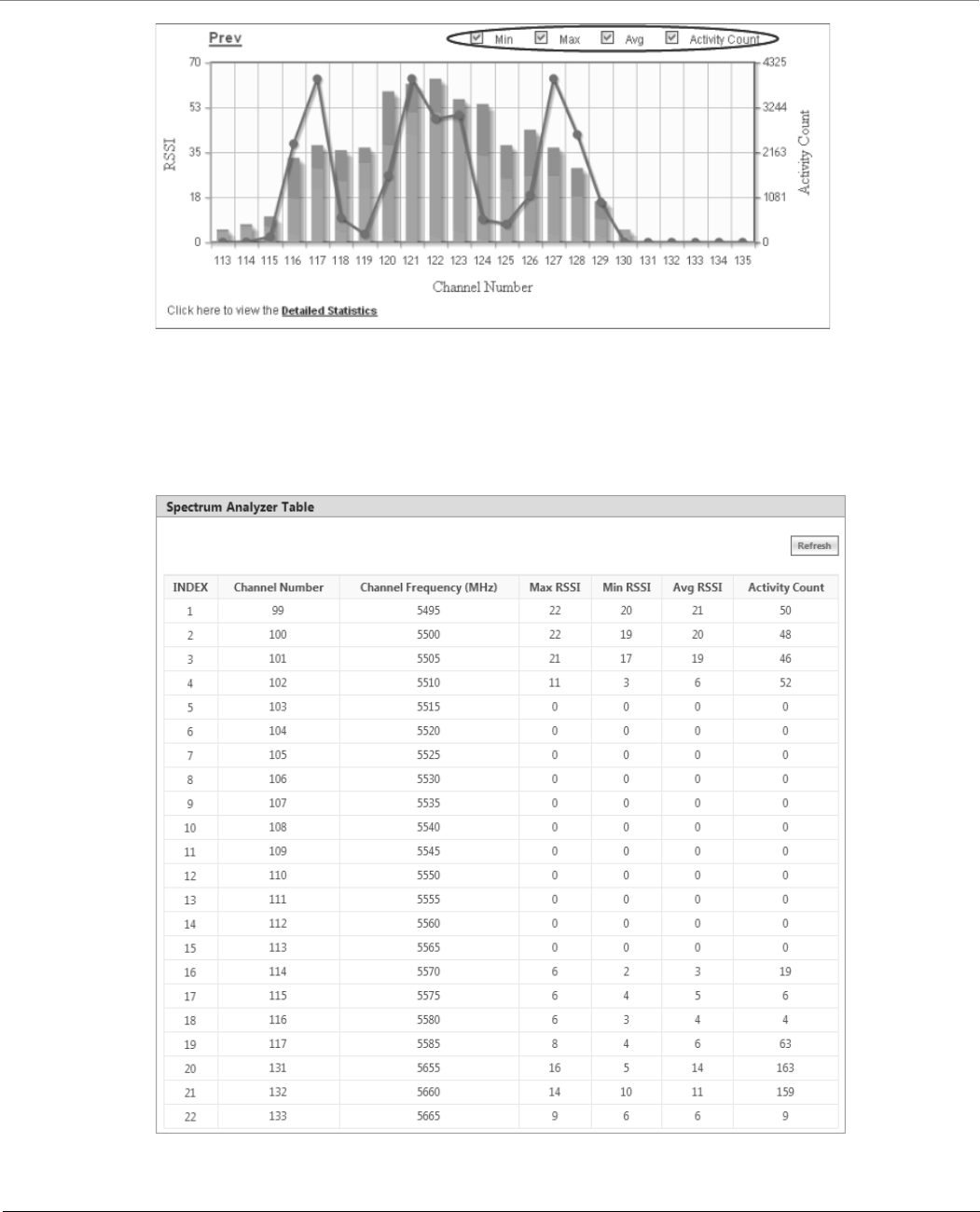
Monitor
Tsunami® 800 & 8000 Series - Software Management Guide 265
Figure 7-48 An Example - Selective Graph Statistics
At a time, the graph represents the statistics of a maximum of 32 channels. To view the graph(s) of the remaining channels,
click Next (available on the upper right corner of the graph). Click Previous to view the statistics of the previous channels.
To view the tabular format of the graph statistics, click Detailed Statistics on the bottom left of the graph. The detailed
statistics is displayed as follows:
Figure 7-49 An Example - Detailed Statistics
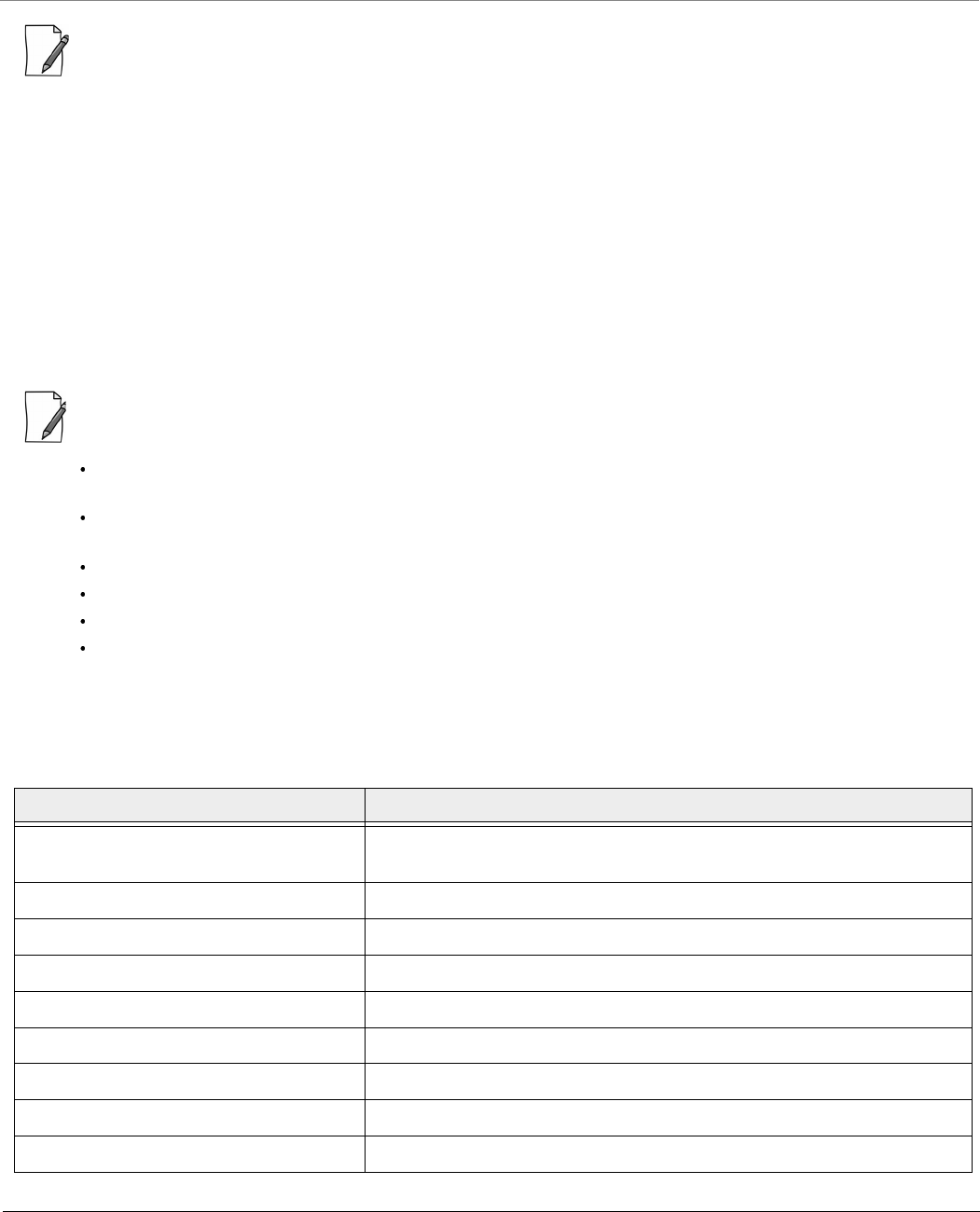
Monitor
Tsunami® 800 & 8000 Series - Software Management Guide 266
: Spectrum Analyzer configuration parameters and results are not persistent across reboots.
7.11.6 Radio Link Test Tool
In general, whenever the network has some performance issue, it is required to identify whether the issue is due to the
wireless link or due to other network parameters. The Radio Link Test (RLT) tool helps to measure and diagnose any
performance issues in the wireless link. At MAC level, this tool internally generates the traffic between the two radios,
monitors the traffic, and generates a test report.The test report will help in analyzing the wireless link performance and other
related issues such as interference, lower throughput, and wireless errors. Especially for the static link establishment, this is
very helpful to check the link between the two radios when installing for the first time or if any performance issues are
noticed after the installation. If the link between the radios is of expected quality, then there is no issue with the wireless link.
In case, if there is any issue due to wireless parameters, the link may need some tuning in configuration such as channel, Data
Rate, Tx power or distance between radios. In spite of all the testing and tuning, if the performance still fails to improve, then
it may be due to installation related issues such as antenna alignment or the physical path. In the worst case, it may be a
hardware related issue.
This is not a replacement for other wireless performance measuring tools and should be used in conjunction with
other tools like Iperf or any other commercial tools.
It is recommended to use this tool with caution on live networks as it will be generating internal traffic which may
impact the network performance.
Radio Link test is an experimental feature and will be improved in future releases.
It is applicable only to 82x devices.
This tool can be accessed through web interface, console commands, and CLI.
Both ends of a link cannot simultaneously run this test.
7.11.6.1 Configuration Options
The configuration options for the Radio Link Test tool are tabulated below:
Parameter Description
Test Duration Time duration for which the Radio Link Test is performed (Default: 60
seconds)
Traffic Direction Direction of the traffic (Downlink/Uplink /Bi-directional)
Traffic Rate Amount of traffic to be generated (K bps)
Periodic Report Interval Time interval in which the report is presented to the user interface (seconds)
Packet Size Generate packet size (Default value: 1500 bytes)
MAC Address Wireless MAC address of the device running in server mode
Verbose Mode Detailed statistics information
Help List of possible options (Usage)
Version Display tool version information
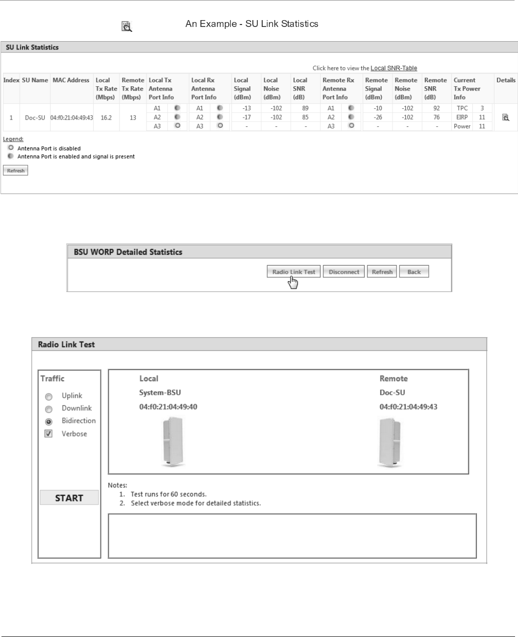
Monitor
Tsunami® 800 & 8000 Series - Software Management Guide 267
To access this tool through web interface, navigate to MONITOR > WORP Statistics > Interface 1 > BSU/SU Link
Statistics > Details. Click as shown in .
Figure 7-50 An Example - SU Link Statistics
The following BSU/SU WORP Detailed Statistics screen appears.
Click the Radio Link Test Button. The following Radio Link Test screen appears.
Figure 7-51 Radio Link Test Tool
In the Radio Link Test screen, you can select the required type of traffic from the given options namely Uplink, Downlink,
and Bidirection. By selecting Verbose along with any one of the traffic options, you can get a detailed test report for the
traffic selected. In the above screen, for example, select Bidirection and Verbose. Next, click the START button.
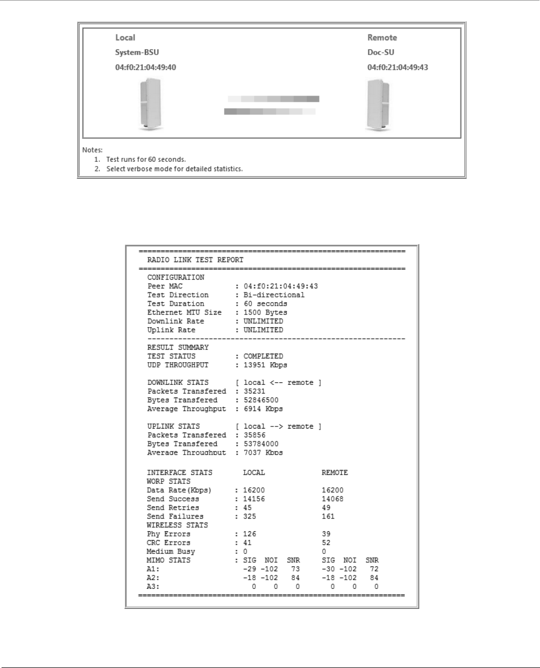
Monitor
Tsunami® 800 & 8000 Series - Software Management Guide 268
Figure 7-52 An Example - Radio Link Test (Bidirectional Traffic with Verbose mode)
The test runs for 60 seconds and displays the Radio Link Test Report as shown below.
Figure 7-53 An Example - Test Report (Bidirectional Traffic with Verbose mode)

Monitor
Tsunami® 800 & 8000 Series - Software Management Guide 269
7.11.6.2 Statistics Options
The test report can be analyzed by using the statistics options tabulated below:
Parameter Description
Traffic Statistics
Tx Packets Total packets transmitted from the moment user initiated the test.
Rx Packets Total packets received from the moment user initiated the test.
Lost Packets Packets lost due to any reason.
Duplicated Packets Number of packets received in duplicate for the already received
packets.
Tx Rate The rate at which the packets are sent.
Rx Rate The rate at which the packets are received.
Wireless Statistics
Phy Errors Total number of error packets received from the moment user
initiated the test . The possible reasons:
It indicates the interference in the wireless medium
Low signal level
CRC Errors Number of packets received with invalid CRC. The possible reasons:
It indicates the interference in the wireless medium
Low signal level
Medium Busy Number of times the radio detected busy medium while trying to
transmit the frame. This could be due to interference on that
specific channel.
WORP Statistics
Send success Refers to the number of data messages sent and acknowledged by
the peer successfully.
Send failure Refers to the number of data messages that are not acknowledged
by the peer even after the specified number of retransmissions.
Send retires Refers to the number of data messages that are re-transmitted and
acknowledged by the peer successfully.
Receive success Refers to the number of data messages received and acknowledged
successfully.
Receive failures Refers to the number of successfully received re-transmitted data
messages.
Receive retires Refers to the number of data messages that were not received
successfully.

Monitor
Tsunami® 800 & 8000 Series - Software Management Guide 270
Using the rlt command options tabulated below, you run the radio link test tool through Web Console.
Signal Statistics
Signal Signal measured at the radio port
Noise Noise detected at the radio port
SNR Signal to Noise Ratio (dB)
Options Description
-t Test duration (Default: 60 seconds)
-i Periodic report display interval (Default: 0 - disabled)
-s Packet size (Default: 1500 bytes)
-o Ignore timeout during test (Default: do not ignore)
Traffic Direction
-d Downlink throughput test with specified traffic rate in K bps (Default: Unlimited)
-u Uplink throughput test with specified traffic rate in K bps (Default: Unlimited)
No option Default: Bi-Directional test with unlimited rate
Miscellaneous
-h, --help Tool usage
-v, --version Tool version number
-V Verbose mode (Enables detailed statistics display)
Parameter Description
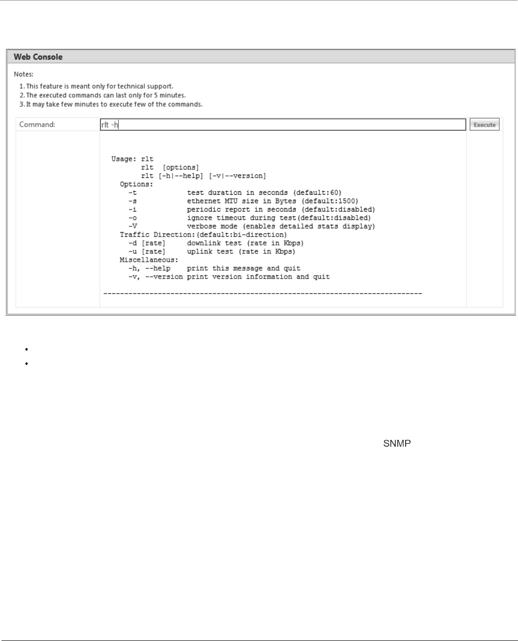
Monitor
Tsunami® 800 & 8000 Series - Software Management Guide 271
To access this tool through Web Console, navigate to MONITOR > Tools > Console Commands. In the Web Console
screen do the following:
Figure 7-54 An Example - Radio Link Test Through Web Console
Command: Type the required rlt command. Click the Execute button.
The command execution is displayed in the Web Console screen.
To run the Radio Link Test tool through Command Line Interface (CLI), refer the Tsunami® 800 and 8000 Series Reference
Guide.
7.12 SNMP v3 Statistics
SNMP v3 statistics can be viewed only when SNMPv3 feature is enabled on the device. See .
To view the SNMPv3 Statistics, navigate to MONITOR > SNMPV3 Statistics. The following SNMP v3 Statistics screen
appears:
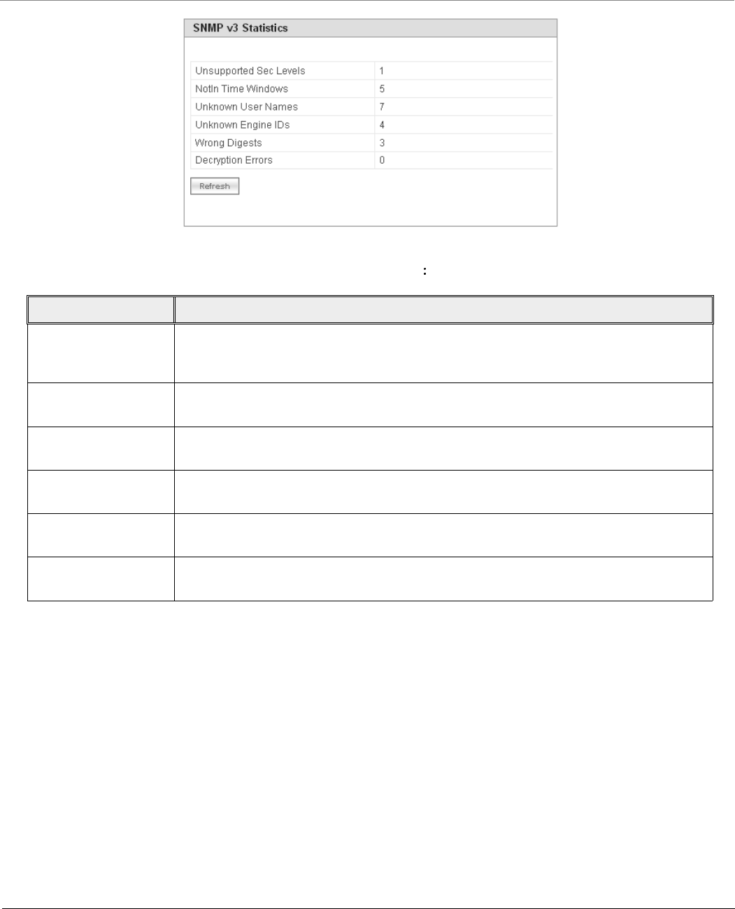
Monitor
Tsunami® 800 & 8000 Series - Software Management Guide 272
Figure 7-55 SNMP v3 Statistics
The following table lists the SNMP v3 parameters and their description
Parameter Description
Unsupported Sec
Levels
This parameter specifies the total number of packets dropped by the SNMP engine
because they requested a security level that was unknown to the SNMP engine or
otherwise unavailable.
Not In Time Windows This parameter specifies the total number of packets dropped by the SNMP engine
because they appeared outside the authoritative SNMP engine's window.
Unknown User Names This parameter specifies the total number of packets dropped by the SNMP engine
because they correspond to a user that is unknown to an SNMP engine.
Unknown Engine IDs This parameter specifies the total number of packets dropped by the SNMP engine
because they correspond to an SNMP Engine ID that is unknown to an SNMP engine.
Wrong Digests This parameter specifies the total number of packets dropped by the SNMP engine
because they do not contain the expected digest value.
Decryption Errors This parameter specifies the total number of packets dropped by the SNMP engine
because they could not be decrypted.
Tsunami® 800 & 8000 Series - Software Management Guide 273
8
Troubleshooting
This chapter helps you to address the problems that might arise while using our device. If the procedures discussed in this
chapter does not provide a solution, or the solution does not solve your problem, check our support site at
which stores all resolved problems in its solution database. Alternatively, you can post a question on
the support site, to a technical person who will reply to your email.
Before you start troubleshooting, check the details in the product documentation available on the support site. For details
about RADIUS, TFTP, Terminal and Telnet programs, and Web Browsers, refer to their appropriate documentation.
In some cases, rebooting the device solves the problem. If nothing else helps, refer to .
This chapter provides information on the following:

Troubleshooting
Tsunami® 800 & 8000 Series - Software Management Guide 274
8.1 PoE Injector
Problem Solution
The Device Does Not
Work
Make sure that you are using a standard UTP
– Category 5e/6 cable in case of MP-8100-BSU, MP-8100-SUA, MP-8150-SUR,
MP-8150-SUR-100, MP-8160-BSU, MP-8160-BS9, MP-8160-SUA,
QB-8100-EPA/LNK, QB-8150-EPR/LNK, QB-8150-LNK-100, QB-8151-EPR/LNK,
MP-8200-BSU, MP-8250-BS9, MP-8250-BS1, MP-8200-SUA,
MP-820-BSU-100, MP-820-SUA-50+, MP-825-SUR-50+,
QB-825-EPR/LNK-50+, and QB-8200-LNK devices
– Category 5/5e cable in case of MP-8150-CPE, MP-8160-CPE-A100,
MP-825-CPE-50, QB-825-EPR/LNK-50, and QB-8150-LNK-12/50
Try a different port on the same PoE Injector hub (remember to move the input port
accordingly) – if it works then there is a problem in the previous RJ45 port or a bad
RJ45 port connection.
Try to connect the device to a different PoE Injector hub.
Try using a different Ethernet cable – if it works, there is probably a fault in the cable
or its connection.
Check the power plug and hub.
If the Ethernet link goes down, check the cable, cable type, switch and hub.
There is No Data Link Verify that the indicator on the device port is “ON.”
Verify that the Ethernet cable from PoE Injector hub to the Ethernet port of the
device is properly connected.
Make sure that you are using a standard UTP
– Category 5e/6 cable in case of MP-8100-BSU, MP-8100-SUA, MP-8150-SUR,
MP-8150-SUR-100, MP-8160-BSU, MP-8160-BS9, MP-8160-SUA,
QB-8100-EPA/LNK, QB-8150-EPR/LNK, QB-8150-LNK-100, QB-8151-EPR/LNK,
MP-8200-BSU, MP-8250-BS9, MP-8250-BS1, MP-8200-SUA,
MP-820-BSU-100, MP-820-SUA-50+, MP-825-SUR-50+,
QB-825-EPR/LNK-50+, and QB-8200-LNK devices
– Category 5/5e cable in case of MP-8150-CPE, MP-8160-CPE-A100,
MP-825-CPE-50, QB-825-EPR/LNK-50, and QB-8150-LNK-12/50
The length of the cable from the Ethernet port of the device to the PoE should be
less than 100 meters (approximately 325 feet).
Try to connect a different device to the same port on the PoE Injector hub – if it
works and a link is established then there is probably a fault in the data link of the
device.
Try to re-connect the cable to a different output port (remember to move the input
port accordingly) – if it works then there is a fault probably in the output or input
port of the PoE Injector hub or a bad RJ45 connection.
Overload Indications Connect the device to a PoE Injector.
Ensure that there is no short over on any of the connected cables.
Move the device into a different output port (remember to move the input port
accordingly) - if it works then there is a fault probably in the previous RJ45 port or
bad RJ45 port connection.
Troubleshooting
Tsunami® 800 & 8000 Series - Software Management Guide 275
8.2 Connectivity Issues
Connectivity issues include any problem that prevents from powering or connecting to the device.
Problem Solution
Does Not Boot - No
LED Activity
Make sure the power source is ON.
Make sure all the cables to the device are connected properly.
Ethernet Link Does
Not Work
Check the Ethernet LED
Solid Green: The Ethernet link is up.
Blinking Green: The Ethernet link is down.
Serial Link Does Not
Work
Double-check the physical network connections.
Make sure your PC terminal program (such as HyperTerminal) is active and
configured to the following values:
– Com Port: (COM1, COM2 and so on depending on your computer);
– Baud rate: 115200; Data bits: 8; Stop bits: 1; Flow Control: None; Parity:
None;
– Line Feeds with Carriage Returns
(In HyperTerminal select: File > Properties > Settings > ASCII Setup > Send Line
Ends with Line Feeds)
: Not applicable to MP-825-CPE-50, and MP-8160-CPE-A100 as it does not
support serial interface.
Cannot Access the
Web Interface
Open a command prompt window and type the Ping command along with the IP
address of the device. For example, ping 10.0.0.1. If the device does not respond,
check if you have the correct IP address. If the device responds then it means the
Ethernet connection is working properly.
Ensure that you are using Microsoft Internet Explorer 7.0 (or later) or Mozilla Firefox
3.0 (or later).
Ensure that you are not using a proxy server for the network connection with your
Web browser.
Ensure that you have not exceeded the maximum number of Web Interfaces or CLI
sessions.
Double-check the physical network connections. Use a well-known device to ensure
the network connection is functioning properly.
Troubleshoot the network infrastructure (check switches, routers, and so on).
: At any point of time, if the device is unable to connect to your network, reset
the device by unplugging and plugging the cables from the PoE.
Troubleshooting
Tsunami® 800 & 8000 Series - Software Management Guide 276
8.3 Surge or Lightning Issues (For Connectorized devices)
8.4 Setup and Configuration Issues
Problem Solution
Surge or Lighting
Problem
In case of any lightning or surge occurrence, check for the conditions specified below:
Check the RF signals by referring to RSSI statistics and if the signal strength has been
lowered considerably, replace the Surge Arrestor.
Unscrew the N-Type connector at the top and visually inspect the Surge Arrestor for
electrical burns. If any, replace it.
Problem Solution
Device Reboots
Continuously
One of the reason for the device to reboot continuously is that the radio card is not
properly placed in the mini-PCI slot. When you power on the device and you do not see
the “WIRELESS NETWORK1 PASSED” in the POST message in the Serial Console,
please contact Proxim’s support site at .
Lost Telnet or SNMP
Password
Perform procedure. This procedure resets system and network
parameters, but does not affect the image of the device. The default HTTP, Telnet, and
SNMP username is admin and password is public.
Device Responds
Slowly
If the device takes a long time to respond, it could mean that:
No DHCP server is available.
The IP address of the device is already in use. Verify that the IP address is assigned
only to the device you are using. Do this by switching off the device and then
pinging the IP address. If there is a response to the ping, another device in the
network is using the same IP address. If the device uses a static IP address, switching
to DHCP mode could solve this problem.
The network traffic is more.
Incorrect Device IP
Address
The default IP address assignment mode is Static and the default IP address of the
device is 169.254.128.132.
If the IP address assignment mode is set to Dynamic, then the DHCP Server will
assign an IP address automatically to the device. If the DHCP server is not available
on your network, then the fall back IP address (169.254.128.132) of the device is
used.
Use ScanTool, to find the current IP address of the device. Once you have the current
IP address, use Web Interface or CLI Interface to change the device IP settings, if
necessary.
If you are using static IP address assignment, and cannot access the device over
Ethernet, refer to .
Perform procedure. This will reset the device to static mode.

Troubleshooting
Tsunami® 800 & 8000 Series - Software Management Guide 277
HTTP Interface or
Telnet Does Not Work
Make sure you are using a compatible browser:
– Microsoft Internet Explorer 7.0 or later
– Mozilla Firefox 3.0 or later
:
When working with Internet Explorer 9 in Windows 2008 Server, navigate to
Internet Options -> Security -> Internet -> Custom Level -> Scripting ->
Active Scripting to enable active scripting.
When working with Internet Explorer 10 and facing web page issues, click the
Broken Page icon available on the right side of address bar.
Make sure you have the correct IP address of the device. Enter the device IP address
in the address bar of the browser, for example http://169.254.128.132.
When the Enter Network Password window appears, enter the User Name and
and Password. The default HTTP username is admin and password is public.
Use CLI, to check the IP Access Table which can restrict access to Telnet and HTTP.
Telnet CLI Does Not
Work
Make sure you have the correct IP address. Enter the device IP address in the Telnet
connection dialog, from a DOS prompt: C:\> telnet <Device IP Address>
Use HTTP, to check the IP Access Table which can restrict access to Telnet and HTTP.
Enable Telnet in Vista or Windows 7 as it is by default disabled.
TFTP Server Does Not
Work
The TFTP server is not properly configured and running
The IP address of the TFTP server is invalid
The upload or download directory is not correctly set
The file name is not correct
Changes in Web
Interface Do Not Take
Effect
1. Restart your Web browser.
2. Log on to the device again and make changes.
3. Reboot the device.
4. Click COMMIT for the changes to take effect.
5. Wait until the device reboots before accessing the device again.
Problem Solution

Troubleshooting
Tsunami® 800 & 8000 Series - Software Management Guide 278
8.5 Application Specific Troubleshooting
Problem Solution
RADIUS
Authentication Server
Services unavailable
If RADIUS Authentication is enabled on the device, then make sure that your network’s
RADIUS servers are operational. Otherwise, clients will not be able to log on to the device.
There are several reasons for the authentication server‘s services to be unavailable. To
make it available,
Make sure you have the proper RADIUS authentication server information setup
configured on the device. Check the RADIUS Authentication Server’s Shared Secret
and Destination Port number (default is 1812; for RADIUS Accounting, the default is
1813).
Make sure the RADIUS authentication server RAS setup matches the device.
TFTP Server If a TFTP server is not configured and running, you will not be able to download and
upload images and configuration files to or from the device. Remember that the TFTP
server need not be local, as long as you have a valid TFTP IP address. Note that you do not
need a TFTP server running unless you want to transfer files to or from the device.
After the TFTP server is installed:
Check to see that TFTP is configured to point to the directory containing the
device Image.
Make sure you have the proper TFTP server IP Address, the proper device image
file name, and that the TFTP server is connected.
Make sure the TFTP server is configured to both Transmit and Receive files (on
the TFTP server’s Security tab), with no automatic shutdown or time-out (on
the Auto Close tab).
Troubleshooting
Tsunami® 800 & 8000 Series - Software Management Guide 279
8.6 Wireless Link Issues
Given below are the possible reasons for a wireless link not getting established and the relevant observations.
Reason(s) Observation
Mismatch in network
name
The Wireless Interface Statistics (In Octets, In Non-Unicast Packets) are incremented
in BSU/End Point A and SU/End Point B.
The WORP counters are not affected.
The remote device is not listed in the Site Survey.
Incorrect or invalid
configured BSU/End
Point A name
The Wireless Interface Statistics (In Octets, In Non-Unicast Packets) are incremented
in SU/End Point B.
The WORP counters are not affected.
The remote device is not listed in the Site Survey.
Mismatch in network
secret
The Wireless Interface Statistics (In Octets, In Non-Unicast Packets) are incremented
in BSU/End Point A and SU/End Point B.
The WORP counters are incremented (Req for Serv, Reg Req, Auth Req, Reg
Attempts, Reg LastReason: Incorrect Parameter) on both ends.
Encryption set to No
Encryption in
BSU/End Point A and
AES Encryption in
SU/End Point B
The Wireless Interface Statistics (In Octets, In Non-Unicast Packets) are incremented
in BSU/End Point A; No decrypt errors are observed in SU/End Point B.
In SU/End Point B, the WORP counters (Announcements, Req for Serv, Reg Attempts,
Reg incomplete, Reg timeout, Reg Last Reason: Timeout) are incremented. In
BSU/End Point A, no WORP counters are incremented except announcements.
The remote device is not listed in the Site Survey.
Encryption set to AES
Encryption in
BSU/End Point A and
No Encryption in
SU/End Point B
The Wireless Statistics counters and WORP counters are not incremented in SU/End
Point B.
The remote device is not listed in the Site Survey.
Encryption set to AES
Encryption in both
BSU/End Point A and
SU/End Point B. A
mismatch in
Encryption key
The Wireless Interface Statistics (In Octets, In Non-Unicast Packets) are incremented
only in SU/End Point B.
The remote device is not listed in the Site Survey.
BSU exceeds the
maximum SU limit
The Wireless Interface Statistics (In Octets, In Non-Unicast Packets) are incremented
in SU/End Point B but fails to authenticate.
The WORP counters (Announcements, Req for Serv, Reg Attempts, Reg Incompletes,
Reg Timeouts, Reg Last Reason: Timeout) are incremented in SU/End Point B.
The remote device is listed in the Site Survey.
Troubleshooting
Tsunami® 800 & 8000 Series - Software Management Guide 280
With multiple link
profiles, the wireless
network performance
is getting affected.
The overall performance of the wireless network gets affected when using multiple link
profiles and atleast one of the subscriber is operating with a lower data rate.
For example, consider a wireless network with a BSU and 5 SU profiles. Each SU is
transmitting data at a data rate as tabulated below. As SU1 is operating at a lower data
rate (6.5 Mbps), the entire performance of the network gets affected.
In order to optimize the network performance, apply QoS.
Given below is an example on how the network performance can be improved by applying
QoS. QoS is applied for SU1 with the following configuration:
PIR based on the ToS value 96
SFC with MIR/CIR= 1Mbps; Priority = 3; Latency/Jitter=10ms
Subscribers SU2...SU5 use the default QoS configuration.
: Given above is just an example and values might vary from case-to-case.
Reason(s) Observation
SU Profile(s) Data Rate Throughput
SU1 6.5 Mbps
Aggregated
throughput can be a
maximum of 13 Mbps
SU2 39 Mbps
SU3 78 Mbps
SU4 130 Mbps
SU5 78 Mbps
Profiles Data Rate Throughput
SU1 6.5 Mbps
With QoS applied for
SU1, expected
throughput is 26 Mbps
SU2 39 Mbps
SU3 78 Mbps
SU4 130 Mbps
SU5 78 Mbps

Troubleshooting
Tsunami® 800 & 8000 Series - Software Management Guide 281
8.7 Wired (Ethernet) Interface Validation
Interference issues
due to wider beam
width of the antenna
MP-825-CPE-50, MP-825-SUR-50+, QB-825-EPR/LNK-50, and
QB-825-EPR/LNK-50+ uses a wider beam width antenna (up to 38 o) with a
gain of 15dBi. Due to its wider beam width, it may pick up more interfering
signals and may report large number of errors compared to other Tsunami
products. Wireless interference may also lead to:
– SNR value fluctuations between the Antenna (A1/A2) ports
– DDRS operation at lower data rates
– Higher number of PHY errors which may result in false RADAR detection in
DFS bands
To overcome these issues, use a spectrum analyzer and switch to a noise-free
channel.
Problem Solution
Wired (Ethernet)
Interface Validation
Run iperf commands
Use iperf commands with –w option as 202k. The throughput is expected to be
equal in both directions and should be comparable from laptop to laptop or desktop
to desktop performance
If the above throughput value is not in the expected range,
Check speed and duplex settings between the device and Personal Computer or
switch or router connected
Make sure the connection established is of same speed and full duplex is as expected
(10 or 100 or 1000)
With auto negotiation, if you notice this issue, then try manually setting the speed
and duplex
Update the Ethernet driver in the Personal Computer to the latest one
Reason(s) Observation

Troubleshooting
Tsunami® 800 & 8000 Series - Software Management Guide 282
8.8 Wireless Interface Validation
Problem Solution
Wireless Interface
Validation
Run iperf commands (You can run Embedded iperf commands only through Telnet.)
iperf –s –w 202k (command for iperf server)
Iperf –c ipaddress –w 202k –t time Period –I <intermediateResultInterval> –P <4 or
6> (command to run iperf client)
– Ipaddress -> of the SU/End Point B or BSU/End Point A device where the iperf
server is running
– P -> No of pairs (Streams)
Use –d option to run bidirectional throughput
Use –r option to run unidirectional throughput one after another without changing
the server and SU ends
If the expected throughput is not achieved, then check the following:
Antenna Alignment
– Note whether the antenna ports are balanced – SNR/RSSI provided for Local
and Remote in the BSU/SU Link Statistics page or by using “aad” command
– Signal difference of <=5 dBm is considered as balanced and recommended
– If the chains are not balanced, then look at the alignment and connectors of
RF cables, used between antenna and device
– If in RMA (Returned from Customer), check the RF cable to radio port
connectivity
– Avoid nearby metal surfaces, if you are using Omni antenna
Data Streams
– Select “Single” stream instead of “Dual” stream mode
– DDRS - with single stream data rate or with Auto mode
Dual stream data rates can be used only when the signal in both antenna ports is
balanced.
Antenna Port Selection
– For devices with 3x3 MIMO radio, make sure you are either enabling all
antenna ports for 3x3 MIMO or using A1 and A3 antenna ports for 2x2
MIMO mode
– For devices with 2x2 MIMO radio, use A1 and A2 antenna ports
– For using single stream, it is mandatory to select antenna port A1
– Enabling all antenna port will not cause any issue even if it is not in use.
Bad Channel
– Check for CRC errors, PHY errors, WORP Retries and WORP Failures in
Monitor Interface Statistics page. If this count increments steadily (Refreshing
the web page is required) then
Either change the channel and check for a better channel
Use Wi-Spy or similar tool and check the environment for better channel
Troubleshooting
Tsunami® 800 & 8000 Series - Software Management Guide 283
8.9 Recovery Procedures
Recovery Procedure is used to restore the device to its factory default operating state. Depending on the device state, the
recovery procedures can be classified under two modes:
1. Operational Mode: Device is up and in running state.
2. Bootloader Mode: Device operating image is deleted.
Problem Solution
Wireless Interface
Validation
Data Rate Issues
– Ensure same data rates are selected if you are using fixed data rate between
BSU/SU and End Point A/End Point B to have predictable throughput and link
– Alternatively, use DDRS with Auto mode enabled
Performance and Stability Issues
– Check the distance between two co-locating devices. The distance between
two co-locating devices should be minimum 3 meters, in order to achieve
good throughput and maintain link stability. The operating adjacent channel
should maintain 5MHz spacing if managed by a single administrator.
– When DDRS is disabled, check the Minimum Required SNR for the current
data rate by navigating to MONITOR --> WORP Statistics --> Interface 1
--> Link Statistics Page --> Click here for Local SNR-Table. If the current
SNR is not meeting the minimum required SNR criteria for the current data
rate, then accordingly reduce the data rate.
– If SNR is more than the maximum optimal SNR limit (MONITOR --> WORP
Statistics --> Interface 1 --> Link Statistics Page --> Click here for Local
SNR-Table) then it causes radio receiver saturation thus impacting the
performance of the link. To overcome this situation, set the TPC appropriately
or enable ATPC to adjust the signal level automatically. Also, enabling DDRS
can help in choosing right data rate automatically.
– To measure and diagnose any performance issues in the wireless link, use the
Radio Link Test Tool. To use this tool, navigate to MONITOR --> WORP
Statistics --> Interface 1 --> Link Statistics Page --> Details -->Click
icon. For detailed description of this tool, refer
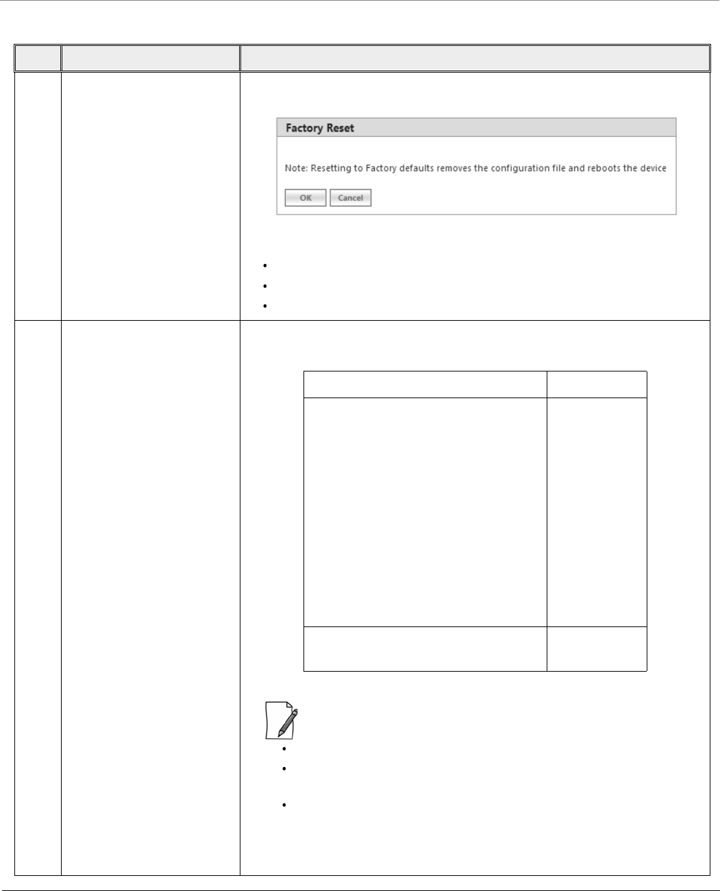
Troubleshooting
Tsunami® 800 & 8000 Series - Software Management Guide 284
8.9.1 Operational Mode
S.No Scenario Recovery Procedure
1 Restore the device to its
factory default configuration
while accessing it through
web interface
In the web interface, navigate to MANAGEMENT > Reset to Factory. The
Factory Reset screen appears:
In the screen, click OK. The device now reboots and comes with:
IP Address: 169.254.128.132
Username: admin
Password: public
2 The device is not accessible
for reasons such as user has
forgotten the web interface
login password,
Management VLAN Id is
changed, wrong VLAN
configuration.
Press and hold the Reload button (use a pin or the end of a paper clip) on the
POE injector for a time frame as mentioned in the following table:
:
To use this procedure, use a PoE injector with Reload functionality.
The device operating image will get deleted, if you press the button
for more than the above mentioned time.
The timings mentioned above are valid from the time the device is
powered UP (that is during POST).
The device now reboots and comes with: IP Address: 169.254.128.132;
Username: admin; and Password: public
Device Timings
MP-8100-BSU; MP-8100-SUA
MP-8150-SUR; MP-8150-SUR-100
MP-8160-BSU; MP-8160-BS9
MP-8160-SUA; MP-8200-BSU
MP-8250-BS9; MP-8250-BS1
MP-8200-SUA; MP-8250-SUR
MP-825-CPE-50; MP-825-SUR-50+;
MP-820-BSU-100; MP-820-SUA-50+
QB-825-EPR/LNK-50+;
QB-825-EPR/LNK-50;
QB-8100-EPA/LNK; QB-8150-EPR/LNK
QB-8150-LNK-100; QB-8151-EPR/LNK
QB-8200-EPA / LNK; QB-8250-EPR / LNK
5 to 6 seconds
MP-8150-CPE; MP-8160-CPE-A100;
QB-8150-LNK-12; QB-8150-LNK-50
15 seconds
Troubleshooting
Tsunami® 800 & 8000 Series - Software Management Guide 285
8.9.2 Bootloader Mode
8.9.3 Load a New Image
Follow one of the procedures below to load a new image to the device:
S.No Scenario Recovery Procedure
1 a) The device operating
image is corrupted for
reasons such as power
interruption while upgrading
(For 82x devices).
After powering-up the device, press and hold the Reload button on the
PoE injector (use a pin or the end of a paper clip) for first 15 seconds and
then release the button between 15-30 seconds. By doing so, the
operating image will get deleted.
:
No reload via Ethernet cross cable.
It is not applicable to MP-825-CPE-50 and QB-825-EPR/LNK-50
devices.
After deleting the operating image, refer and
sections to load the firmware onto the device.
b) The device operating
image is corrupted for
reasons such as power
interruption while upgrading
(For all devices).
Do one of the following:
While powering the device, press and hold the Reload button on the PoE
injector (use a pin or the end of a paper clip) for 15 seconds. By doing so,
the operating image will get deleted.
Use a 4-pair (Gigabit) cross over Ethernet cable between the PoE and the
device. By doing so, the reload functionality gets activated and forcibly
deletes the operating image.
If you are having serial access to the device during POST, press SHIFT+u to
enter into forced user mode of the bootloader. From the Bootloader
prompt, enter the command firmware_delete.
After deleting the operating image, refer and
sections to load the firmware onto the device.
2 The device is not accessible
for reasons such as user has
forgotten the web interface
login password,
Management VLAN Id is
changed, and wrong VLAN
configuration.
And, you do not have a
reload capable PoE but Serial
access is possible
If you are having serial access to the device during POST, press SHIFT+u to enter
into forced user mode of the bootloader. From the Bootloader prompt, enter the
command config_delete.
Next, issue the command reboot.
The device now reboots and comes with: IP Address: 169.254.128.132;
Username: admin; and Password: public

Troubleshooting
Tsunami® 800 & 8000 Series - Software Management Guide 286
: A new image cannot be downloaded using Bootloader CLI onto MP-825-CPE-50, MP-8160-CPE-A100 and
QB-825-EPR-50 as it does not provide a serial interface.
8.9.3.1 Using the ScanTool
To download the firmware image to the device, you will need an Ethernet connection to the computer on which the TFTP
server resides and to a computer that is running ScanTool (this is either two separate computers connected to the same
network or a single computer running both programs).
ScanTool automatically detects the device that does not have a valid software image. The TFTP Server and Image File Name
parameters are enabled in the ScanTool’s screen so that you can download a new image to the device. (These fields
are disabled, if ScanTool detects a software image on the device). See .
Preparing to Download the Device Image
Before starting the download process, you need to know the device IP Address, Subnet Mask, the TFTP Server IP Address, and
the Image file name. Make sure the TFTP server is running and properly configured to point to the folder containing the
image to be downloaded.
Download Procedure
Follow these steps to download a software image to the device by using ScanTool:
1. Download the latest software from , and copy it to the default directory of the TFTP server.
2. Launch Proxim’s ScanTool.
3. Highlight the entry for the device that you want to update and click Change.
4. Set IP Address Type to Static.
: You need to assign static IP information temporarily to the device since its DHCP client functionality is not
available when no image is installed on the device.
5. Now enter the IP address, Subnet mask, Default-gateway, Server - IP address and the image filename.
6. Click OK. The device will reboot and the download starts automatically.
7. Click OK when prompted to return to the Scan List screen after the device has been updated successfully.
8. Click Cancel to close the ScanTool.
After the download process is completed, the device will reboot and initialize. After successful initialization, the device is
ready to be configured.
8.9.3.2 Using the Bootloader CLI
To download the new device image, you will need an Ethernet connection to the computer on which the TFTP server resides.
This can be any computer on the LAN or connected to the device with an Ethernet cable.
You must also connect the device to a computer with a standard serial cable and use a terminal client. From the terminal,
enter the CLI commands to set the IP address of the device and to download the device image.
Preparing to Download the device image
Before starting, you need to know the device IP Address, Subnet Mask, the TFTP Server IP Address, and the device image file
name. Make sure the TFTP server is running and configured to point to the default directory containing the image to be
downloaded.
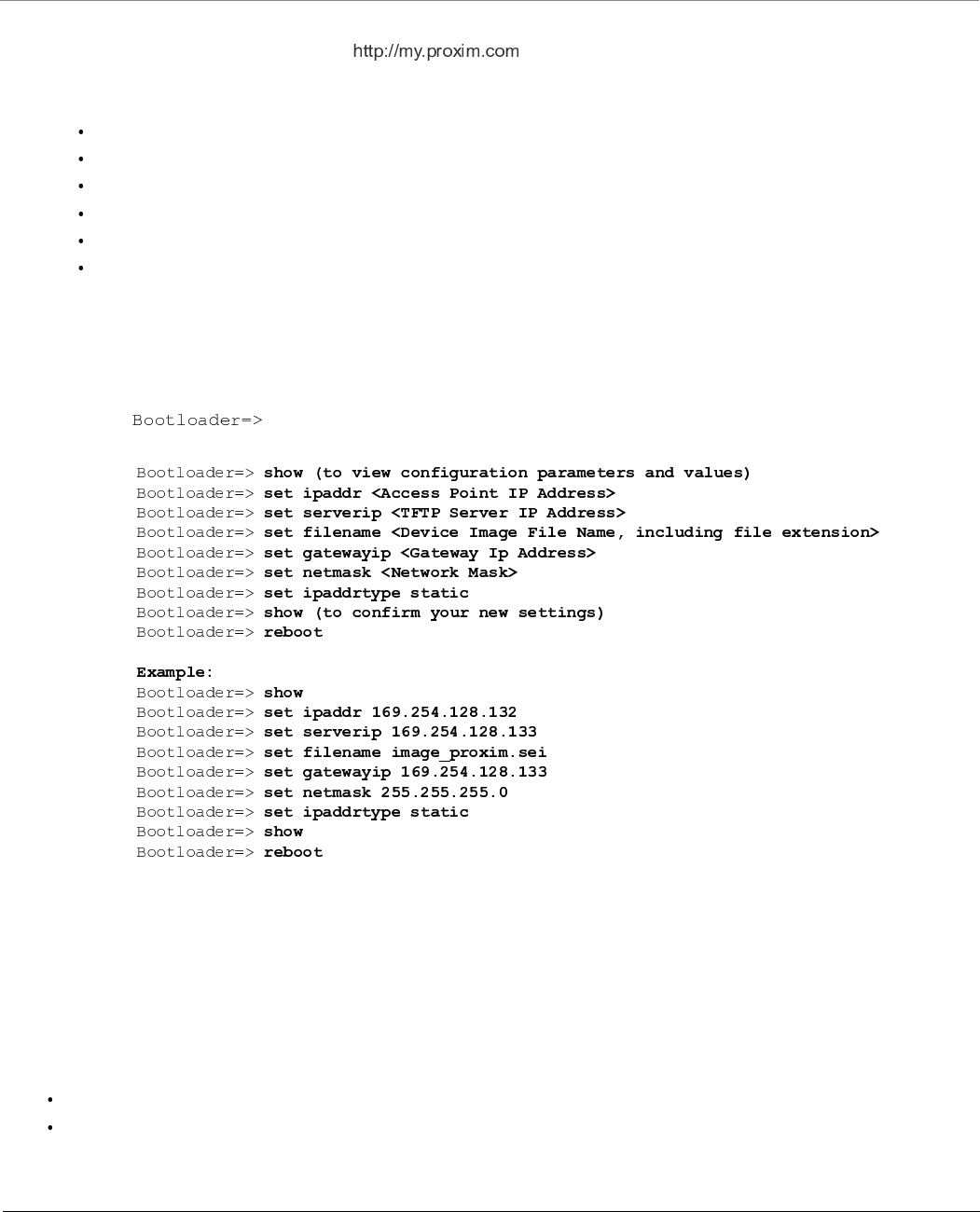
Troubleshooting
Tsunami® 800 & 8000 Series - Software Management Guide 287
Download Procedure
1. Download the latest software from , and copy it to the default directory of the TFTP server.
2. Connect the device serial port to your computer’s serial port.
3. Open your terminal emulator program and set the following connection properties:
Com Port: COM1, COM2 and so on, depending on your computer
Baud Rate: 115200
Data Bits: 8
Stop Bits: 1
Flow Control: None
Parity: None
4. Under File > Properties > Settings > ASCII Setup, enable the Send line ends with line feeds option.
Terminal Emulator program sends a line return at the end of each line of code.
The terminal display shows Power On Self Tests (POST) activity. After approximately 30 seconds, a message indicates:
Starting ScanTool interface, press any key to enter CLI 5”. After this message appears, press any key. Now the
bootloader prompt appears as below:
5. Enter the following commands:
The device will reboot and then download the image file. When the download process is complete, configure the
device.
8.9.4 Setting IP Address using Serial Port
If the ScanTool fails to scan the device and users knows the login credentials then you can set the IP address for the device
using serial port.
8.9.4.1 Hardware and Software Requirements
Standard serial (RS-232) cable
ASCII Terminal software
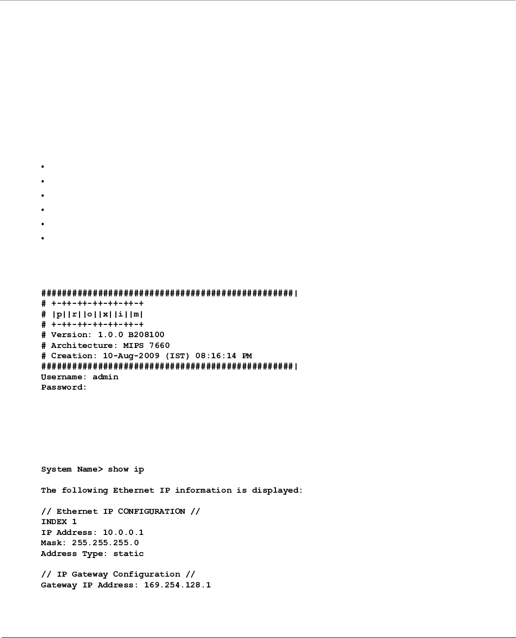
Troubleshooting
Tsunami® 800 & 8000 Series - Software Management Guide 288
8.9.4.2 Attach the Serial Port Cable
1. Connect one end of the serial cable to the device and the other end to a serial port on your computer.
2. Power on the computer and the device.
8.9.4.3 Initializing the IP Address using CLI
After connecting the cable to the serial port, you can use the CLI to communicate with the device. CLI supports the
most-generic terminal emulation programs. In addition, many web sites offer shareware or commercial terminal programs
that you can download. Once the IP address has been assigned, you can use the HTTP interface or the Telnet to complete the
configuration.
Follow these steps to assign an IP address to the device:
1. Open your terminal emulation program and set the following connection properties:
Com Port: COM1, COM2, and so on depending on your computer
Baud Rate: 115200
Data Bits: 8
Stop Bits: 1
Flow Control: None
Parity: None
The terminal display shows Power On Self Tests (POST) activity, and then displays the software version. It prompts you
to enter the CLI username and password. The commands to enter the username and password are as follows:
This process may take up to 90 seconds.
2. Enter the CLI Username and password. By default username is admin and password is public. The terminal displays a
welcome message and then the CLI Prompt. Enter ‘show ip’ as shown below:
3. Change the IP address and other network values using the following CLI commands (use your own IP address and
Subnet mask).
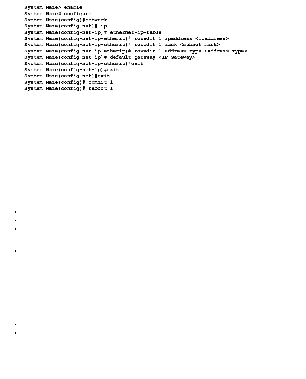
Troubleshooting
Tsunami® 800 & 8000 Series - Software Management Guide 289
4. After the device reboots, verify the new IP address by reconnecting to the CLI. Alternatively, you can ping the device
from a network computer to confirm that the new IP address has taken effect.
When a proper IP address is set, use HTTP interface or Telnet to configure the rest of the operating parameters of the
device.
8.10 Spectrum Analyzer
The ultimate way to discover whether there is a source of interference is to use a Spectrum Analyzer. Usually, the antenna is
connected to the analyzer when measuring. By turning the antenna 360°, one can check the direction of the interference.
The analyzer will also display the frequencies and the level of signal is detected. Proxim recommends performing the test at
various locations to find the most ideal location for the equipment.
8.10.1 Avoiding Interference
When a source of interference is identified and when the level and frequencies are known, the next step is to avoid the
interference. Some of the following actions can be tried:
Change the channel to a frequency that has no or least interference.
Try changing the antenna polarization.
A small beam antenna looks only in one particular direction. Because of the higher gain of such an antenna, lowering
the output power or adding extra attenuation might be required to stay legal. This solution cannot help when the
source of interference is right behind the remote site.
Adjusting the antenna angle/height can help to reduce the interference.
Move the antennas to a different location on the premises. This causes the devices to look from a different angle, causing a
different pattern in the reception of the signals. Use obstructions such as buildings, when possible, to shield from the
interference.
8.10.2 Conclusion
A spectrum analyzer can be a great help to identify whether interference might be causing link problems on the device.
Before checking for interference, the link should be verified by testing in an isolated environment, to make sure that the
hardware works and your configurations are correct. The path analysis, cabling and antennas should be checked as well.
Base Announces should increase continuously.
Registration Requests and Authentication Requests should be divisible by 3. WORP is designed in a way that each
registration sequence starts with 3 identical requests. It is not a problem if, once in a while, one of those requests is
missing. Missing requests frequently is to be avoided.

Troubleshooting
Tsunami® 800 & 8000 Series - Software Management Guide 290
Monitor / Per Station (Information per connected remote partner): Check that the received signal level (RSL) is the
same on both sides. This should be the case if output power is the same. Two different RSLs indicate a broken
transmitter or receiver. A significant difference between Local Noise and Remote Noise could indicate a source of
interference near the site with the highest noise. Normally, noise is about –80 dBm at 36 Mbps. This number can vary
from situation to situation, of course, also in a healthy environment.
8.11 Miscellaneous
8.11.1 Unable to Retrieve Event Logs through HTTPS
If using Internet Explorer 7 and are not able to retrieve event logs through HTTPS, do the following:
1. Open Internet Explorer
2. Navigate to Tool > Internet Options > Advanced
3. Go to Security and uncheck/unselect Do not save encrypted pages to disk
Alternatively, use Mozilla Firefox 3.5 or later.
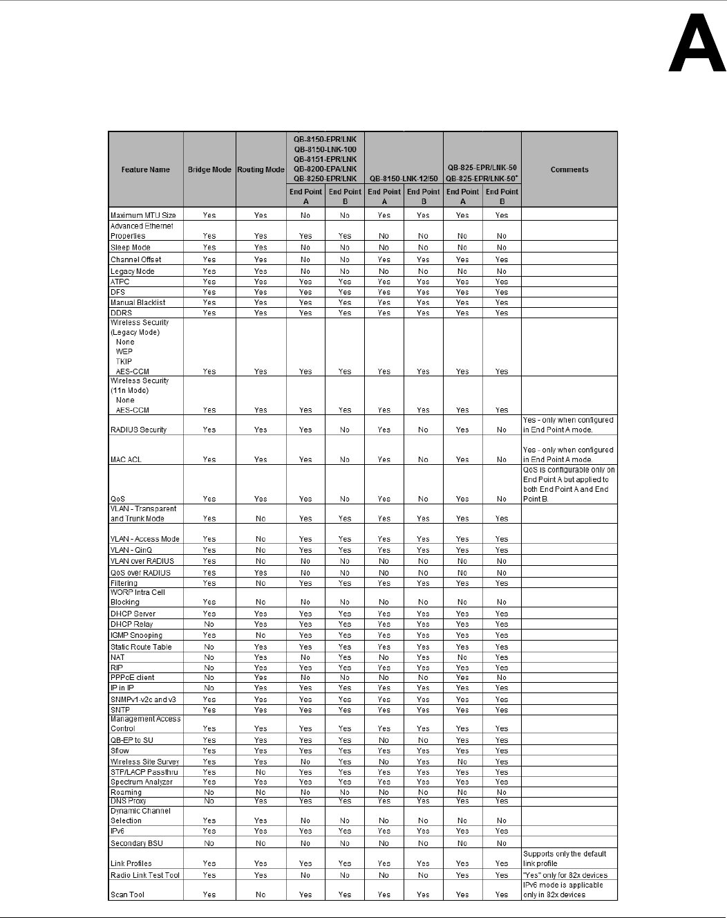
Tsunami® 800 & 8000 Series - Software Management Guide 291
Feature Applicability
Given below are the feature(s) applicable to the respective point-to-point devices:
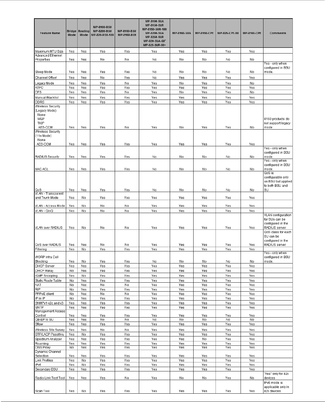
Feature Applicability
Tsunami® 800 & 8000 Series - Software Management Guide 292
Given below are the feature(s) applicable to the respective point-to-multipoint devices:

Tsunami® 800 & 8000 Series - Software Management Guide 293
Parameters Requiring Reboot
Given below are the parameters that require the device to reboot.
Parameter(s) Web Page(s) Applicable Device Mode*
System Configuration
Radio Mode BASIC CONFIGURATION
ADVANCED CONFIGURATION -> System
All
Frequency Domain BASIC CONFIGURATION
ADVANCED CONFIGURATION -> System
All
Network Mode ADVANCED CONFIGURATION -> System All
Maximum MTU ADVANCED CONFIGURATION -> System All
Frequency Filter
Lower Edge
ADVANCED CONFIGURATION -> System All
Frequency Filter
Upper Edge
ADVANCED CONFIGURATION -> System All
IP Configuration (Bridge Mode)
Ethernet
BASIC CONFIGURATION
ADVANCED CONFIGURATION -> Network -> IP Configuration
All
Default Gateway IP
Address
All
DNS All
IP Configuration (Routing Mode)
Ethernet
BASIC CONFIGURATION
ADVANCED CONFIGURATION -> Network -> IP Configuration
All
Wireless All
Wireless (With
PPPoE)
SU Mode
Default Gateway IP
Address
All
DNS (Primary and
Secondary Address)
All
NAT
Status ADVANCED CONFIGURATION -> Network -> NAT SU Mode / End Mode B mode
Dynamic Start Port ADVANCED CONFIGURATION -> Network -> NAT SU Mode / End Mode B mode
Dynamic End Port ADVANCED CONFIGURATION -> Network -> NAT SU Mode / End Mode B mode
PPPoE
Status ADVANCED CONFIGURATION -> Network -> PPPoE Client SU Mode
Ethernet Interface Properties
Admin Status ADVANCED CONFIGURATION -> Network -> Ethernet All

Parameters Requiring Reboot
Tsunami® 800 & 8000 Series - Software Management Guide 294
Wireless Properties
Channel Bandwidth BASIC CONFIGURATION
ADVANCED CONFIGURATION -> Wireless -> Interface1 ->
Properties
All
Channel Offset ADVANCED CONFIGURATION -> Wireless -> Properties Applicable only to,
MP-820-BSU-100
MP-820-SUA-50+
MP-825-SUR-50+
MP-825-CPE-50
MP-8150-CPE
MP-8160-BSU
MP-8160-BS9
MP-8160-SUA
MP-8160-CPE-A100
QB-825-EPR/LNK-50
QB-825-EPR/LNK-50+
QB-8150-LNK-12/50
Auto Channel
Selection
BASIC CONFIGURATION
ADVANCED CONFIGURATION -> Wireless -> Interface1 ->
Properties
Applicable only to BSU.
Legacy Mode BASIC CONFIGURATION
ADVANCED CONFIGURATION -> Wireless -> Interface1 ->
Properties
Applicable only to,
MP-820-BSU-100
MP-820-SUA-50+
MP-825-SUR-50+
MP-825-CPE-50
MP-8100-BSU
MP-8100-SUA
MP-8150-SUR
MP-8150-CPE
MP-8150-SUR-100
MP-8200-BSU
MP-8200-SUA
MP-8250-BS9
MP-8250-BS1
MP-8250-SUR
Frequency Extension ADVANCED CONFIGURATION -> Wireless -> Interface1 ->
Properties -> MIMO Properties -> MIMO
All
Upgrade Firmware and Configuration
Upgrade Firmware MANAGEMENT -> File Management -> Upgrade Firmware All
Parameter(s) Web Page(s) Applicable Device Mode*

Parameters Requiring Reboot
Tsunami® 800 & 8000 Series - Software Management Guide 295
Upgrade
Configuration
MANAGEMENT -> File Management -> Upgrade Configuration All
HTTP / HTTPS
Admin Password
MANAGEMENT -> Services -> HTTP / HTTPS
All
Monitor Password All
HTTP All
HTTP Port All
HTTPS All
Parameter(s) Web Page(s) Applicable Device Mode*
SNMP (If SNMP v1-v2c is enabled)
SNMP
MANAGEMENT -> Services -> SNMP
All
Version All
Read Password All
Read / Write
Password
All
SNMP Trap Host
Table
All
SNMP (If SNMP v3 is enabled)
SNMP
MANAGEMENT -> Services -> SNMP
All
Version All
Security Level All
Priv Protocol All
Priv Password All
Auth Protocol All
Auth Password All
SNMP Trap Host
Table
All
Telnet / SSH
Parameter(s) Web Page(s) Applicable Device Mode*

Parameters Requiring Reboot
Tsunami® 800 & 8000 Series - Software Management Guide 296
* BSU: Refers to a Base Station
SU Mode: Refers to both SU and CPE
End Point A Mode: Refers to a device in End Point A mode
End Point B Mode: Refers to a device in End Point B mode
Admin Password
MANAGEMENT -> Services -> Telnet / SSH
All
Monitor Password All
Telnet All
Telnet Port All
Telnet Sessions All
SSH All
SSH Port All
SSH Sessions All
Management Access Control
Access Table Status
MANAGEMENT -> Access Control
All
Management
Access Control
Table
All
Reset to Factory MANAGEMENT -> Reset to Factory All
Convert QB to MP MANAGEMENT -> Convert QB to MP Applicable only to
QB-825-EPR/LNK-50
QB-825-EPR/LNK-50+
QB-8100-EPA/LNK
QB-8150-EPR/LNK
QB-8150-LNK-100
QB-8151-EPR/LNK
QB-8200-LNK
Parameter(s) Web Page(s) Applicable Device Mode*
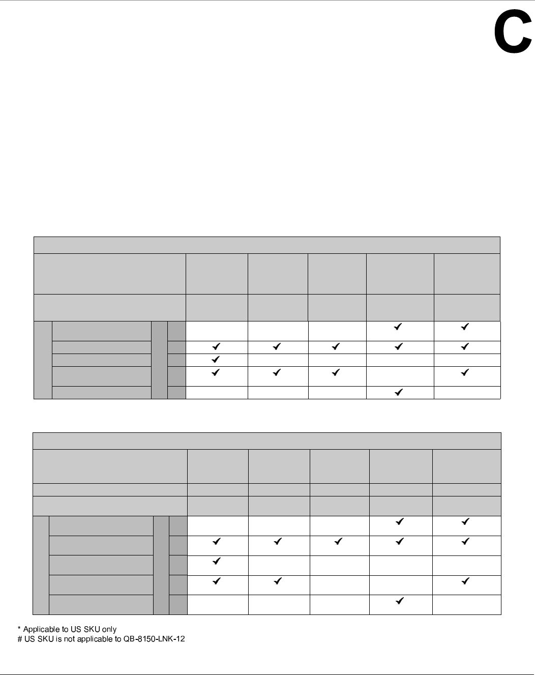
Tsunami® 800 & 8000 Series - Software Management Guide 297
Frequency Domains and Channels
Introduction
The Tsunami® point-to-point and point-to-multipoint products are available in two SKUs: United States (US) and rest of the
World (WD) markets. Depending on the SKU, the device is hard programmed at factory per the regulatory domain.
Regulatory domain controls the list of frequency domains that are available in that SKU. Further each frequency domain will
define the country specific regulatory rules and frequency bands. The frequency domains can be easily configured using the
Web Interface as it is a drop down list with all the available domains. The following table lists all the Tsunami® 800 and 8000
Series products with the applicable frequency domains and their corresponding ENUM values, SKUs supported and licensed
frequency bands.
US Frequency Domains
Point to Multipoint Devices
Product(s) MP-8100-BSU
MP-8100-SUA
MP-8150-SUR
MP-8150-SUR-100
MP-8150-CPE MP-8200-BSU / SUA
MP-8250-BS9 / BS1
MP-8250-SUR
MP-820-BSU-100
MP-820-SUA-50+
MP-825-CPE-50
MP-825-SUR-50+
Licensed Bands (in GHz) 2.4,
4.9,
5.0
5.0 5.0 4.9,
5.0
5.0
Frequency Domains
United States 5 GHz - US*
ENUM Values
1
United States 5.8 GHz - US* 2
United States 2.4 GHz - US* 3
US2 (5.3 and 5.8GHz) - US* 22
United States 4.9 GHz 28
Point to Point Devices
Product(s) QB-8100-EPA/LNK QB-8150-EPR
QB-8150-LNK
QB-8150-LNK-100
QB-8151-EPR/LNK
QB-8150-LNK-12#
QB-8150-LNK-50
QB-8200-EPA/LNK
QB-8250-EPR/LNK
QB-825-EPR/LNK-50
QB-825-EPR/LNK-50+
US US US US US
Licensed Bands (in GHz) 2.4,
5.0
5.0 5.0 4.9,
5.0
5.0
Frequency Domains
United States 5 GHz - US*
ENUM Values
1
United States 5.8GHz - US* 2
United States 2.4 GHz - US* 3
US2 (5.3 and 5.8GHz) - US* 22
United States 4.9 GHz 28
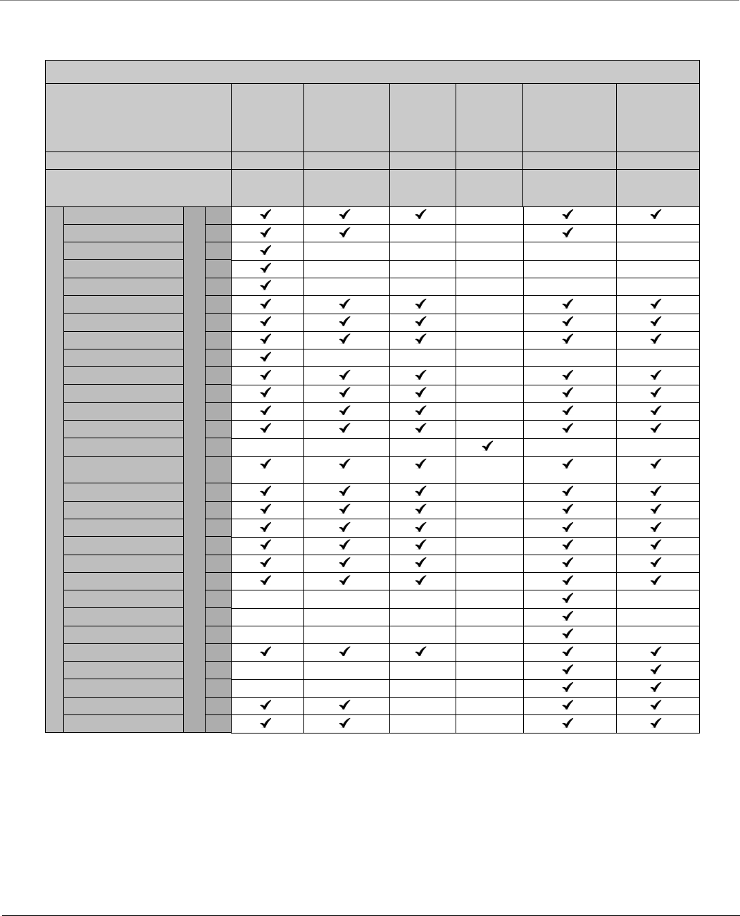
Frequency Domains and Channels
Tsunami® 800 & 8000 Series - Software Management Guide 298
World Frequency Domains
Point to Multipoint Devices
Product(s) MP-8100-BSU
MP-8100-SUA
MP-8150-SUR
MP-8150-SUR-100
MP-8150-CPE MP-8160-BSU
MP-8160-BS9
MP-8160-SUA
MP-8160-CPE
MP-8200-BSU / SUA
MP-8250-BS9 / BS1
MP-8250-SUR
MP-820-BSU-100
MP-820-SUA-50+
MP-825-SUR-50+
MP-825-CPE-50
WD WD WD WD WD WD
Licensed Bands (in GHz) 2.4,
4.9,
5.0
4.9,
5.0
5.0 6.4 4.9,
5.0
5.0
Frequency Domains
World 5 GHz
ENUM Values
4
World 4.9 GHz 5
World 2.4 GHz 6
World 2.3 GHz 7
World 2.5 GHz 8
Canada 5 GHz 9
WD Europe 5.8 GHz 10
WD Europe 5.4 GHz 11
WD-Europe 2.4 GHz 12
Russia 5 GHz 13
Taiwan 5 GHz 14
WD United States 5 GHz 15
Canada 5.8 GHz 16
World 6.4 GHz 17
WD UK 5.8 GHz 20
World 5.9 GHz 21
India 5.8 GHz 23
Brazil 5.4 GHz 24
Brazil 5.8 GHz 25
Australia 5.4 GHz 26
Australia 5.8 GHz 27
WD United States 4.9 GHz 29
Canada 4.9 GHz 30
WD Japan 4.9 GHz 31
Legacy 5GHz 32
WD Japan 5.6 GHz 33
WD United States 5.8 34
World 5.8 GHz 40
Indonesia 5.7 GHz 41
Frequency Domains and Channels
Tsunami® 800 & 8000 Series - Software Management Guide 299
Point to Point Devices
Product(s) QB-8100-EPA/LNK QB-8150-EPR
QB-8150-LNK
QB-8150-LNK-100
QB-8151-EPR/LNK
QB-8150-LNK-12#
QB-8150-LNK-50
QB-8200-EPA/LNK
QB-8250-EPR/LNK
QB-825-EPR/LNK-50
QB-825-EPR/LNK-50+
WD WD WD WD WD
Licensed Bands (in GHz) 2.4,
4.9,
5.0
4.9,
5.0
5.0 4.9,
5.0
5.0
Frequency Domains
World 5 GHz
ENUM Values
4
World 4.9 GHz 5
World 2.4 GHz 6
World 2.3 GHz 7
World 2.5 GHz 8
Canada 5 GHz 9
WD-Europe 5.8 GHz 10
WD-Europe 5.4 GHz 11
WD-Europe 2.4 GHz 12
Russia 5 GHz 13
Taiwan 5 GHz 14
WD United States 5 GHz 15
Canada 5.8 GHz 16
World 6.4 GHz 17
World UK 5.8 GHz 20
World 5.9 GHz 21
India 5.8 GHz 23
Brazil 5.4 GHz 24
Brazil 5.8 GHz 25
Australia 5.4 GHz 26
Australia 5.8 GHz 27
WD United States 4.9 GHz 29
Canada 4.9 GHz 30
WD Japan 4.9 GHz 31
Legacy 5 GHz 32
WD Japan 5.6 GHz 33
WD United States 5.8 GHz 34
World 5.8 GHz 40
Indonesia 5.7 GHz 41
Frequency Domains and Channels
Tsunami® 800 & 8000 Series - Software Management Guide 300
Europe and Japan Frequency Domains
When the device is configured by using CLI or SNMP, care has to be taken to set the domains by using a predefined ENUM
value.
Example: The CLI commands to set WORLD 5 GHz as frequency domain are as follows:
Point to Multipoint Devices
Product(s) MP-8100-BSU
MP-8100-SUA
MP-8150-SUR
MP-8150-SUR-100
MP-8200-BSU / SUA
MP-8250-BS9 / BS1
MP-8250-SUR
MP-820-BSU-100
MP-820-SUA-50+MP-825-SUR-50+
MP-825-CPE-50
EU EU EU JP EU EU
Licensed Bands (in GHz) 2.4,
4.9,
5.0
4.9,
5.0
4.9,
5.0
4.9,
5.0
4.9,
5.0
5.0
Frequency Domains
Japan 2.4 GHz
ENUM Values
18
Japan 4.9 GHz 19
UK 5.8 GHz 35
Europe 5.8 GHz 36
Europe 5.4 GHz 37
Europe 2.4 GHz 38
Japan 5.6 GHz 39
Point to Point Devices
Product(s) QB-8100-EPA/LNK QB-8150-EPR
QB-8150-LNK
QB-8150-LNK-100
QB-8151-EPR/LNK
QB-8200-EPA/LNK
QB-8250-EPR/LNK
QB-825-EPR/LNK-50
QB-825-EPR/LNK-50+
EU EU JP EU EU
Licensed Bands (in GHz) 2.4,
4.9,
5.0
4.9,
5.0
4.9,
5.0
4.9,
5.0
5.0
Frequency Domains
Japan 2.4 GHz
ENUM Values
18
Japan 4.9 GHz 19
UK 5.8 GHz 35
Europe 5.8 GHz 36
Europe 5.4 GHz 37
Europe 2.4 GHz 38
Japan 5.6 GHz 39

Frequency Domains and Channels
Tsunami® 800 & 8000 Series - Software Management Guide 301
2.4 GHz Channels
Frequency
Domain
Frequency
Band
(Start
Frequency ~
End
Frequency in
MHz)
Allowed Channels (Center Frequency in GHz)
5 MHz 10 MHz 20 MHz 40 PLUS
MHz
40 MINUS
MHz
US SKU
United States
2.4 GHz
2412 ~ 2462 1 (2412),
2 (2417)...
10 (2457),
11 (2462).
1 (2412),
2 (2417)...
10 (2457),
11 (2462).
1 (2412),
2 (2417)...
10 (2457),
11 (2462).
1 (2412),
2 (2417)...
6 (2437),
7 (2442).
5 (2432),
6 (2437)...
10 (2457),
11 (2462).
World SKU
World 2.3 GHz 2277 ~ 2397 100 (2277),
101 (2282)...
123 (2392),
124 (2397).
100 (2277),
101 (2282)...
122 (2387),
123 (2392).
101 (2282),
102 (2287)...
121(2382),
122 (2387).
101 (2282),
102 (2287)...
117 (2362),
118 (2367).
105 (2302),
106(2307)...
121(2382),
122 (2387).
World 2.4 GHz 2412 ~ 2472 1 (2412),
2 (2417)...
12 (2467),
13 (2472).
1 (2412),
2 (2417)...
12 (2467),
13 (2472).
1 (2412),
2 (2417)...
12 (2467),
13 (2472).
1 (2412),
2 (2417)...
8 (2447),
9 (2452).
5 (2432),
6 (2437)...
12 (2467),
13 (2472).
World 2.5 GHz 2477 ~ 2507 200(2477),
201(2482)...
205 (2502),
206(2507).
200(2477),
201(2482)...
205 (2502),
206(2507).
201(2482),
202 (2487)...
204(2497),
205 (2502).
- -
WD-Europe 2.4
GHz
2412 ~ 2472 1 (2412),
2 (2417)...
12 (2467),
13 (2472).
1 (2412),
2 (2417)...
12 (2467),
13 (2472).
1 (2412),
2 (2417)...
12 (2467),
13 (2472).
1 (2412),
2 (2417)...
8 (2447),
9 (2452).
5 (2432),
6 (2437)...
12 (2467),
13 (2472).
EU SKU
Europe 2.4 GHz 2412 ~ 2472 1 (2412),
2 (2417)...
12 (2467),
13 (2472).
1 (2412),
2 (2417)...
12 (2467),
13 (2472).
1 (2412),
2 (2417)...
12 (2467),
13 (2472).
1 (2412),
2 (2417)...
8 (2447),
9 (2452).
5 (2432),
6 (2437)...
12 (2467),
13 (2472).
: All DFS countries support only 20 and 40 MHz channel bandwidths.

Frequency Domains and Channels
Tsunami® 800 & 8000 Series - Software Management Guide 302
4.9 and 5 GHz Channels
Frequency
Domain
Frequency Band
(Start Frequency ~
End Frequency in
MHz)
Allowed Channels (Center Frequency in GHz)
5 MHz
10 MHz 20 MHz 40 PLUS
MHz
40 MINUS
MHz
US SKU
United
States 5 GHz
5260 ~ 5320 (DFS)
5500 ~ 5580 (DFS)
5660 ~ 5700 (DFS)
5745 ~ 5825 (non-DFS)
- - 52(5260),
53(5265)...
63(5315),
64(5320).
100(5500),
101(5505)...
115(5575),
116(5580).
132(5660),
133(5665)...
139(5695),
140(5700).
149(5745),
150(5750)...
164(5820),
165(5825).
52(5260),
53(5265)...
59(5295),
60(5300).
100(5500),
101(5505)...
111(5555),
112(5560).
133(5665),
134(5670)...
135(5675),
136(5680).
149(5745),
150(5750)...
160(5800),
161(5805).
56(5280),
57(5285)...
63(5315),
64(5320).
104(5520),
105(5525)...
115(5575),
116(5580).
136(5680),
137(5685)...
139(5695),
140(5700).
153(5765),
154(5770)...
164(5820),
165(5825).
United
States 5.8
GHz
5740 ~ 5830 (Non-DFS) 148(5740),
149(5745)...
165(5825),
166(5830).
149(5745),
150(5750)...
164(5820),
165(5825).
149(5745),
150(5750)...
164(5820),
165(5825).
149(5745),
150(5750)...
160(5800),
161(5805).
153(5765),
154(5770)...
164(5820),
165(5825).
United
States2 (5.3,
5.8 GHz)
5260 ~ 5320 (DFS)
5745 ~ 5825 (Non-DFS)
- - 52(5260),
53(5265)...
63(5315),
64(5320).
149(5745),
150(5750)...
164(5820),
165(5825).
52(5260),
53(5265)...
59(5295),
60(5300).
149(5745),
150(5750)...
160(5800),
161(5805).
56(5280),
57(5285)...
63(5315),
64(5320).
153(5765),
154(5770)...
164(5820),
165(5825).
United
States 4.9
GHz
4942 ~ 4987 (Non-DFS) 5(4942.5),
15(4947.5)...
85(4982.5),
95(4987.5).
10(4945),
20(4950)...
80(4980),
90(4985).
20(4950),
30(4955)...
70(4975),
80(4980).
- -
Japan SKU
Japan 4.9 4912 ~ 4980 (Non-DFS) 182(4912.5),
183(4917.5)...
188(4942.5),
189(4947.5).
183(4915),
184(4920)...
188(4940),
189(4945).
184(4920),
188(4940)...
192(4960),
196(4980).
184(4920),
185(4925),
191(4955)...
192(4960).
188(4940),
189(4945),
195(4975)...
196(4980).

Frequency Domains and Channels
Tsunami® 800 & 8000 Series - Software Management Guide 303
Japan 5.6 5500 ~ 5700 (DFS) - - 100(5500)
104(5520)
108(5540)
112(5560)
116(5580)
120(5600)
124(5620)
128(5640)
132(5660)
136(5680)
140(5700)
100(5500)
108(5540)
116(5580)
124(5620)
136(5680)
104(5520)
112(5560)
120(5600)
128(5640)
140(5700)
World SKU
WD United
States 5 GHz
5255 ~ 5325 (DFS)
5495 ~ 5585 (DFS)
5655 ~ 5705 (DFS)
5740 ~ 5830 (non-DFS)
- - 52(5260),
53(5265)...
63(5315),
64(5320).
100(5500),
101(5505)...
115(5575),
116(5580).
132(5660),
133(5665)...
139(5695),
140(5700).
149(5745),
150(5750)...
164(5820),
165(5825)
52(5260),
53(5265)...
59(5295),
60(5300).
100(5500),
101(5505)...
111(5555),
112(5560).
133(5665),
134(5670),
135(5675),
136(5680).
149(5745),
150(5750)...
160(5800),
161(5805).
56(5280),
57(5285)...
63(5315),
64(5320).
104(5520),
105(5525)...
115(5575),
116(5580).
136(5680),
137(5685)...
139(5695),
140(5700).
153(5765),
154(5770)...
164(5820),
165(5825).
World 5 GHz 5155 ~ 6075 (Non-DFS)
Please note that 8200 &
82x SKUs support upto
5920 MHz frequency.
31(5155),
32(5160)...
214(6070),
215(6075).
31(5155),
32(5160)...
214(6070),
215(6075).
32(5160),
33(5165)...
213(6065),
214(6070).
32(5160),
33(5165)...
209(6045),
210(6050).
36(5180),
37(5185)...
213(6065),
214(6070).
World 4.9
GHz
4905 ~ 4995 (Non-DFS) 181(4905),
182(4910)…
187(4935),
188(4940).
10(4945),
20(4950)…
100(4990),
110(4995).
181(4905),
182(4910)…
187(4935),
188(4940).
10(4945),
20(4950)…
100(4990),
110(4995).
182(4910),
183(4915)…
187(4935),
188(4940).
10(4945),
20(4950)…
90(4985),
100(4990).
182(4910),
183(4915)…
187(4935),
188(4940).
10(4945),
20(4950)…
50(4965),
60(4970).
186(4930),
187(4935),
188(4940),
10(4945),
20(4950)…
90(4985),
100(4990).
Frequency
Domain
Frequency Band
(Start Frequency ~
End Frequency in
MHz)
Allowed Channels (Center Frequency in GHz)
5 MHz
10 MHz 20 MHz 40 PLUS
MHz
40 MINUS
MHz

Frequency Domains and Channels
Tsunami® 800 & 8000 Series - Software Management Guide 304
World 5.9
GHz
5880 ~ 5920 (Non-DFS) 176(5880),
177(5885)...
183(5915),
184(5920).
176(5880),
177(5885)...
183(5915),
184(5920).
177(5885),
178(5890)...
182(5910),
183(5915).
177(5885)
178(5890)
179(5895)
181(5905)
182(5910)
183(5915)
Canada 5
GHz
5255 ~ 5325 (DFS)
5495 ~ 5585 (DFS)
5655 ~ 5705 (DFS)
- - 52(5260),
53(5265)...
63(5315),
64(5320).
100(5500),
101(5505)...
115(5575),
116(5580).
132(5660),
133(5665)...
139(5695),
140(5700).
52(5260),
53(5265)...
59(5295),
60(5300).
100(5500),
101(5505)...
111(5555),
112(5560).
132(5660),
133(5665)...
135(5675),
136(5680).
56(5280),
57(5285)...
63(5315),
64(5320).
104(5520),
105(5525)...
115(5575),
116(5580).
136(5680),
137(5685)...
139(5695),
140(5700).
WD-Europe
5.4 GHz
5495 ~ 5585 (DFS)
5655 ~ 5705 (DFS)
- - 100(5500),
101(5505)...
115(5575),
116(5580).
132(5660),
133(5665)...
139(5695),
140(5700).
100(5500),
101(5505)...
111(5555),
112(5560).
132(5660),
133(5665)...
135(5675),
136(5680).
104(5520),
105(5525)...
115(5575),
116(5580).
136(5680),
137(5685)...
139(5695),
140(5700).
WD-Europe
5.8 GHz
5735 ~ 5870 (DFS) - - 149(5745),
150(5750)...
172(5860),
173(5865).
149(5745),
150(5750)…
168(5840),
169(5845).
153(5765),
154(5770)...
172(5860),
173(5865).
Russia
5 GHz
5155 ~ 6075 (Non-DFS)
Please note that 8200 &
82x SKUs support upto
5920 MHz frequency.
31(5155),
32(5160)...
214(6070),
215(6075).
31(5155),
32(5160)...
214(6070),
215(6075).
32(5160),
33(5165)...
213(6065),
214(6070).
32(5160),
33(5165)...
209(6045),
210(6050).
36(5180),
37(5185)...
213(6065),
214(6070).
Taiwan 5
GHz
5495 ~ 5705 (DFS)
5740 ~ 5810 (Non-DFS)
- - 100(5500),
101(5505)...
139(5695),
140(5700).
149(5745),
150(5750)...
160(5800),
161(5805).
100(5500),
101(5505)...
135(5675),
136(5680).
149(5745),
150(5750)...
156(5780),
157(5785).
104(5520),
105(5525)...
139(5695),
140(5700).
153(5765),
154(5770)...
160(5800),
161(5805).
Frequency
Domain
Frequency Band
(Start Frequency ~
End Frequency in
MHz)
Allowed Channels (Center Frequency in GHz)
5 MHz
10 MHz 20 MHz 40 PLUS
MHz
40 MINUS
MHz

Frequency Domains and Channels
Tsunami® 800 & 8000 Series - Software Management Guide 305
India 5.8
GHz
5830 ~ 5870 (Non-DFS) 166(5830),
167(5835)...
173(5865),
174(5870).
166(5830),
167(5835)...
173(5865),
174(5870).
167(5835),
168(5840)...
172(5860),
173(5865).
167(5835)
168(5840)
169(5845)
171(5855)
172(5860)
173(5865)
Canada
5.8 GHz
5735 ~ 5855 (Non-DFS) 147(5735),
148(5740)...
170(5850),
171(5855).
147(5735),
148(5740)...
170(5850),
171(5855).
148(5740),
149(5745)...
169(5845),
170(5850).
148(5740),
149(5745)...
165(5825),
166(5830).
152(5760),
153(5765)...
169(5845),
170(5850).
WD U.K
5.8 GHz
5730 ~ 5790 (DFS)
5820 ~ 5845 (DFS)
- - 147(5735),
148(5740)...
156(5780),
157(5785).
167(5835).
147(5735),
148(5740)...
152(5760),
153(5765).
151(5755),
152(5760)...
156(5780),
157(5785).
Australia
5.4 GHz
5475 ~ 5595 (DFS)
5655 ~ 5720 (DFS)
- - 96(5480),
97(5485)…
117(5585),
118(5590).
132(5660),
133(5665)…
142(5710),
143(5715).
96(5480),
97(5485)…
113(5565),
114(5570).
132(5660),
133(5665)…
138(5690),
139(5695).
100(5500),
101(5505)…
117(5585),
118(5590).
136(5680),
137(5685)…
142(5710),
143(5715).
Australia
5.8 GHz
5730 ~ 5845 (Non-DFS) 146(5730),
147(5735)…
168(5840),
169(5845).
146(5730),
147(5735)...
148(5740),
169(5845).
147(5735),
148(5740)…
167(5835),
168(5840).
147(5735),
148(5740)...
163(5815),
164(5820).
151(5755),
152(5760)…
167(5835),
168(5840).
Brazil
5.4 GHz
5475 ~ 5720 (DFS) - - 96(5480),
97(5485)…
142(5710),
143(5715).
96(5480),
97(5485)…
138(5690),
139(5695).
100(5500),
101(5505)…
142(5710),
143(5715).
Brazil
5.8 GHz
5730 ~ 5845 (Non-DFS) 146(5730),
147(5735)...
168(5840),
169(5845).
146(5730),
147(5735)...
168(5840),
169(5845).
147(5735),
148(5740)...
167(5835),
168(5840).
147(5735),
148(5740)...
163(5815),
164(5820).
151(5755),
152(5760)...
167(5835),
168(5840).
Canada 4.9
GHz
4945 ~ 4985 (Non-DFS) 10(4945),
20(4950)...
80(4980),
90(4985).
10(4945),
20(4950)...
80(4980),
90(4985).
20(4950),
30(4955)...
70(4975),
80(4980).
20(4950),
30(4955),
40(4960).
60(4970),
70(4975),
80(4980).
Frequency
Domain
Frequency Band
(Start Frequency ~
End Frequency in
MHz)
Allowed Channels (Center Frequency in GHz)
5 MHz
10 MHz 20 MHz 40 PLUS
MHz
40 MINUS
MHz

Frequency Domains and Channels
Tsunami® 800 & 8000 Series - Software Management Guide 306
Legacy 5GHz 5150 ~ 6080 (Non-DFS)
Please note that 8200 &
82x SKUs support upto
5920 MHz frequency.
30(5150),
31(5155)...
215(6075),
216(6080).
30(5150),
32(5160)...
214(6070),
216(6080).
30(5150),
34(5170)...
210(6050),
216(6070).
- -
WD Japan
4.9
4912 ~ 4980 (Non-DFS)
Please note that 8100
SKUs does not support
this frequency.
182(4912.5),
183(4917.5)...
188(4942.5),
189(4947.5).
183(4915),
184(4920)...
188(4940),
189(4945).
184(4920),
188(4940),
192(4960),
196(4980).
184(4920)
192(4960)
188(4940)
196(4980)
WD-Japan
5.6
5500 ~ 5700 (DFS) - - 100(5500)
104(5520)
108(5540)
112(5560)
116(5580)
120(5600)
124(5620)
128(5640)
132(5660)
136(5680)
140(5700)
100(5500)
108(5540)
116(5580)
124(5620)
136(5680)
104(5520)
112(5560)
120(5600)
128(5640)
140(5700)
WD United
States 4.9
GHz
4942 ~ 4987 (Non-DFS) 5(4942.5),
15(4947.5)...
85(4982.5),
95(4987.5),
10(4945),
20(4950)...
80(4980),
90(4985).
20(4950),
30(4955)...
70(4975),
80(4980).
- -
WD United
States 5.8
GHz
5740 ~ 5830 (Non-DFS) 148(5740),
149(5745)...
165(5825),
166(5830).
149(5745),
150(5750)...
164(5820),
165(5825).
149(5745),
150(5750)...
164(5820),
165(5825).
149(5745),
150(5750)...
160(5800),
161(5805).
153(5765),
154(5770)...
164(5820),
165(5825).
World 5.8
GHz
5720 ~ 5855 (Non-DFS) 144(5720),
145(5725)...
170(5850),
171(5855).
144(5720),
145(5725)...
170(5850),
171(5855).
145(5725),
146(5730)...
169(5845),
170(5850).
145(5725),
146(5730)...
165(5825),
166(5830).
149(5745),
150(5750)...
169(5845),
170(5850).
Indonesia
5.7 GHz
5730 ~ 5820 (Non-DFS) 146(5730),
147(5735)...
163(5815),
164(5820).
146(5730),
147(5735)...
163(5815),
164(5820).
147(5735),
148(5740)...
162(5810),
163(5815).
147(5735),
148(5740)...
158(5790),
159(5795).
151(5755),
152(5760)...
162(5810),
163(5815).
Frequency
Domain
Frequency Band
(Start Frequency ~
End Frequency in
MHz)
Allowed Channels (Center Frequency in GHz)
5 MHz
10 MHz 20 MHz 40 PLUS
MHz
40 MINUS
MHz

Frequency Domains and Channels
Tsunami® 800 & 8000 Series - Software Management Guide 307
EU SKU
U.K
5.8 GHz
5730 ~ 5790 (DFS)
5820 ~ 5845 (DFS)
- - 147(5735),
148(5740)...
156(5780),
157(5785).
167(5835)
147(5735),
148(5740)...
152(5760),
153(5765).
151(5755),
152(5760)...
156(5780),
157(5785).
Europe
5.8 GHz
5735 ~ 5870 (DFS) - - 149(5745),
150(5750)...
172(5860),
173(5865).
149(5745),
150(5750)…
168(5840),
169(5845).
153(5765),
154(5770)...
172(5860),
173(5865).
Europe
5.4 GHz
5495 ~ 5585 (DFS)
5655 ~ 5705 (DFS)
- - 100(5500),
101(5505)...
115(5575),
116(5580).
132(5660),
133(5665)...
139(5695),
140(5700).
100(5500),
101(5505)...
111(5555),
112(5560).
132(5660),
133(5665)...
135(5675),
136(5680).
104(5520),
105(5525)...
115(5575),
116(5580).
136(5680),
137(5685)...
139(5695),
140(5700).
Frequency
Domain
Frequency Band
(Start Frequency ~
End Frequency in
MHz)
Allowed Channels (Center Frequency in GHz)
5 MHz
10 MHz 20 MHz 40 PLUS
MHz
40 MINUS
MHz
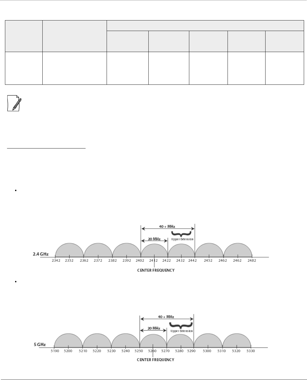
Frequency Domains and Channels
Tsunami® 800 & 8000 Series - Software Management Guide 308
6.4 GHz Channels
: The center frequency listed in the above tables are based on channel offset set to ‘0’. If channel offset is set to any
value other than ‘0’ then the center frequency will be shifted accordingly. You can set the channel offset ranging from
-2 to +2 MHz in MP-8150-CPE, MP-8160-BSU, MP-8160-SUA, MP-8160-CPE-A100, MP-825-CPE-50,
MP-820-BSU-100, MP-820-SUA-50+, MP-825-SUR-50+, QB-8150-EPR/LNK-12/50, QB-825-EPR/LNK-50, and
QB-825-EPR/LNK-50+.
Details for 40MHz Bandwidth
While choosing 40MHz bandwidth, you can select 40 PLUS (Upper Extension) or 40 MINUS (Lower Extension). 40 PLUS means
the center frequency calculation is done for 20MHz and add another 20MHz to the top edge of 20MHz. 40 MINUS means
the center frequency calculation is done for 20MHz and add another 20MHz to the bottom edge of 20MHz.
For 40 PLUS
2.4GHz ->
– Channel 1 = 2412 MHz
– Bandwidth starts from 2403 MHz and ends at 2442 MHz
5GHz ->
– Channel 52 = 5260 MHz
– Bandwidth starts from 5251 MHz and ends at 5290 MHz
Frequency
Domain
Frequency Band
(Start Frequency ~
End Frequency in
MHz)
Allowed Channels (Center Frequency)
5 MHz 10 MHz 20 MHz 40 PLUS
MHz
40 MINUS
MHz
World 6.4
GHz
5905 ~ 6420 181 (5905),
182 (5910)...
283 (6415),
284 (6420).
181 (5905),
182 (5910)...
283 (6415),
284 (6420).
182 (5910),
183 (5915)...
282 (6410),
283 (6415).
182 (5910),
183 (5915)...
278 (6390),
279 (6395).
186 (5930)
187 (5935)...
282 (6410),
283 (6415).
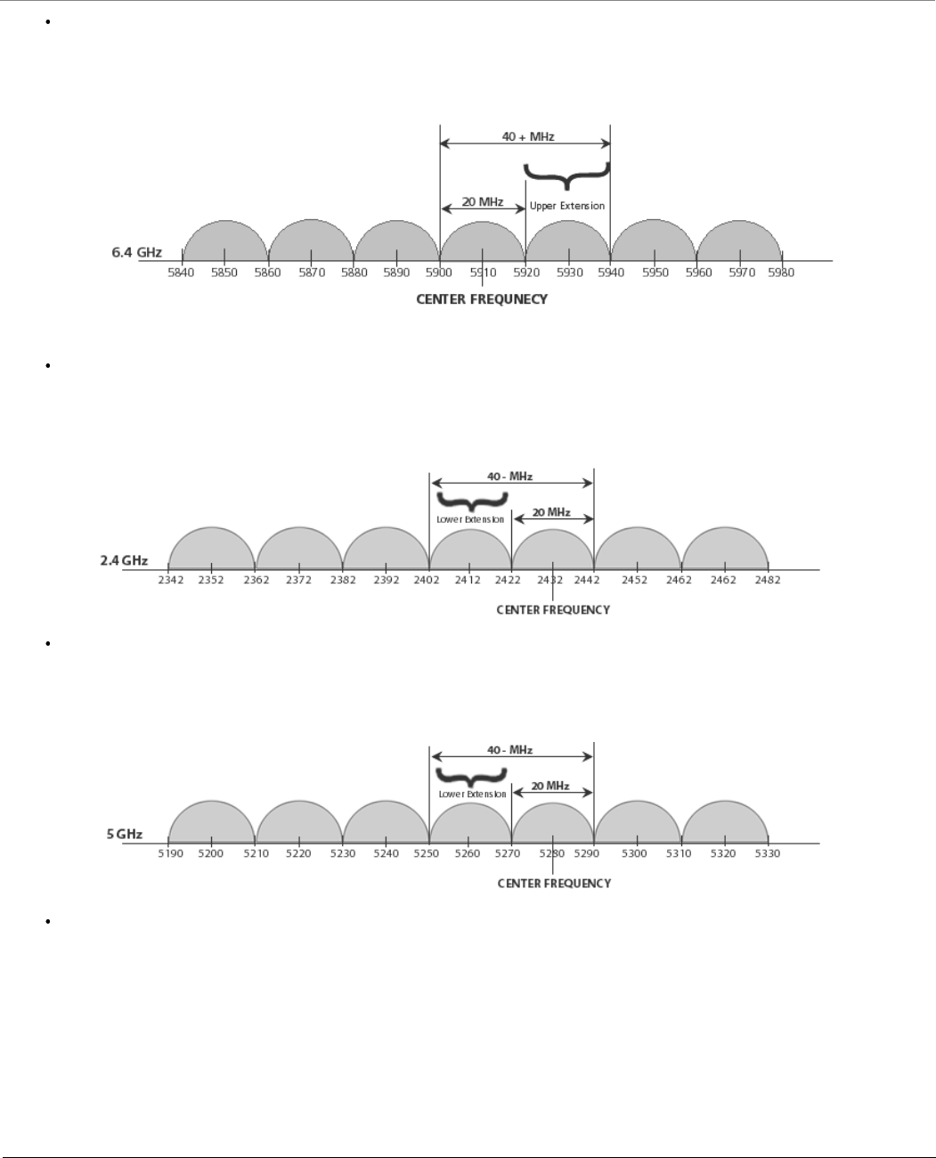
Frequency Domains and Channels
Tsunami® 800 & 8000 Series - Software Management Guide 309
6.4GHz ->
– Channel 181 = 5910 MHz
– Bandwidth starts from 5901 MHz and ends at 5940 MHz
For 40 MINUS
2.4GHz ->
– Channel 5 = 2432 MHz
– Bandwidth starts from 2403 MHz and ends at 2442 MHz
5GHz ->
– Channel 56 = 5280 MHz
– Bandwidth starts from 5251 MHz and ends at 5290 MHz
6.4GHz ->
– Channel 186 = 5930 MHz
– Bandwidth starts from 5901 MHz and ends at 5940 MHz
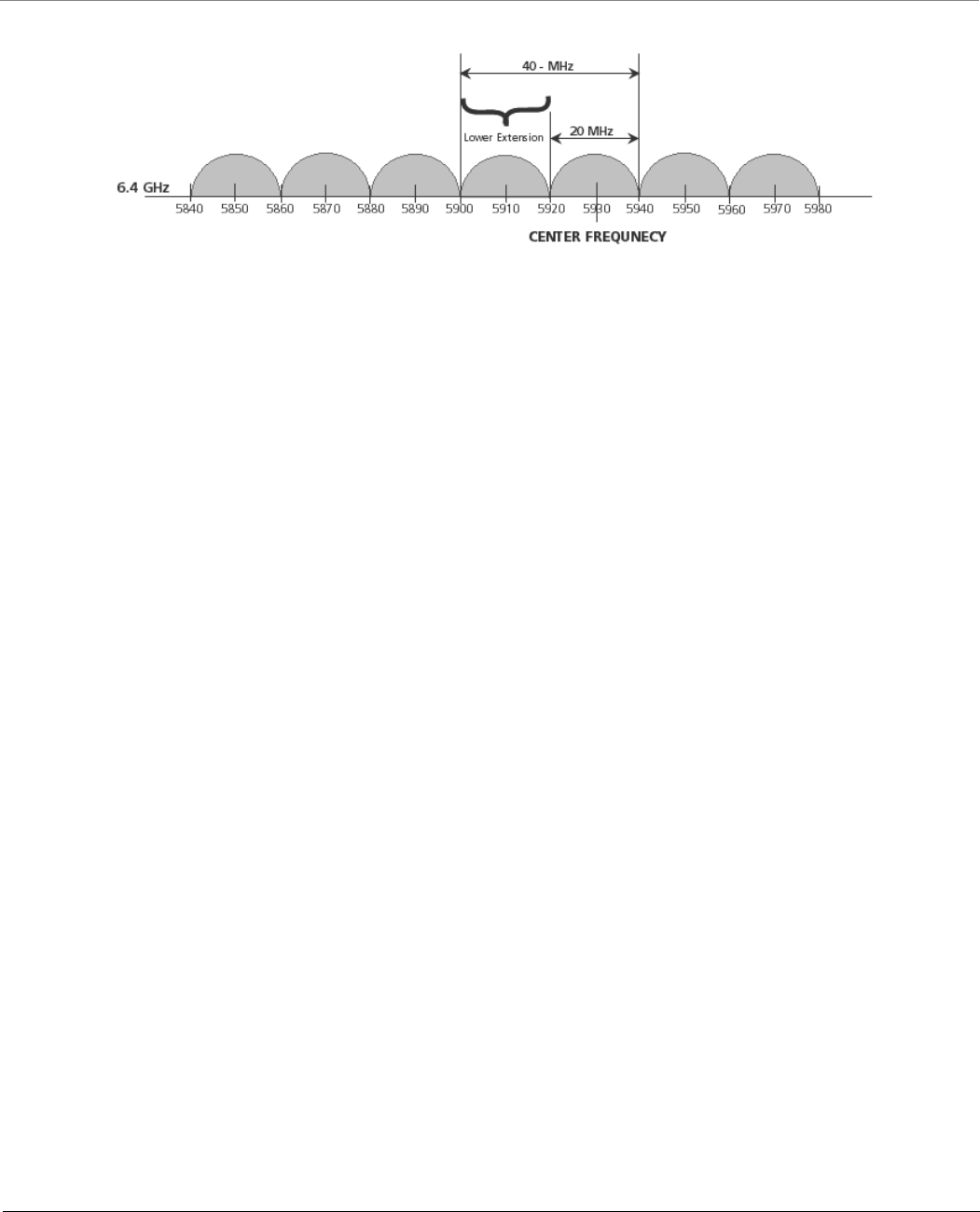
Frequency Domains and Channels
Tsunami® 800 & 8000 Series - Software Management Guide 310
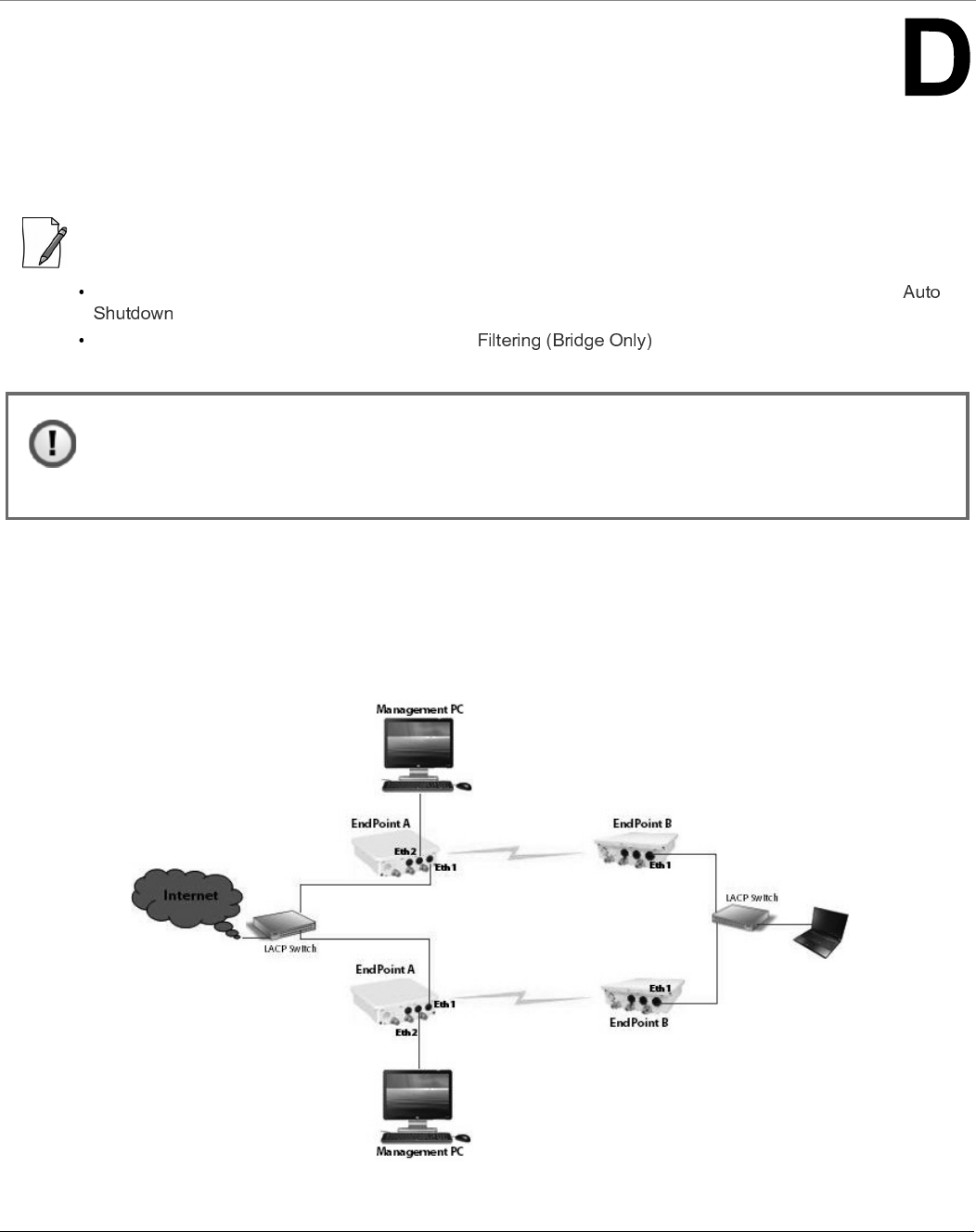
Tsunami® 800 & 8000 Series - Software Management Guide 311
LACP - Device Management
Tsunami Quickbridge® devices that are part of the LACP link cannot be managed through the switches, so it is
recommended to use the second Ethernet port for management.
:
When using second Ethernet port for management, ensure to disable Auto Shutdown for Ethernet2. See
).
STP/LACP Frames should be set to passthru. See
In this chapter, we have chosen the following two examples to explain the device management in the LACP link, by using the
second Ethernet port.
Example1
Figure D-1 Device Management with No VLAN
: The second Ethernet port is POE out; it should be connected via a passive POE (Without the AC power
plugged-in) or Gigabit 48 VDC Injector (GIG-POE-INJ-48VDC-T) (without 48 VDC power plugged-in).
Directly connecting the Ethernet port2 of the device to the PC Ethernet NIC may damage the PC NIC port
or Ethernet port on the switch.
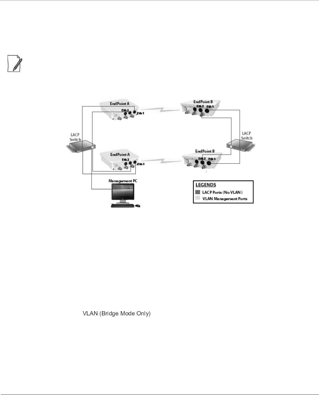
LACP - Device Management
Tsunami® 800 & 8000 Series - Software Management Guide 312
In this example, we have considered a network with two QuickBridge links each supporting LACP mode. In this setup, VLAN
is not configured on both LACP switches and devices.
The Ethernet1 of all the devices is connected to the LACP port and is used for data transfer.
To manage the devices, use a dedicated management Personal Computer per QuickBridge link. Use Ethernet2 port of the
device to connect the Personal Computer.
: In Fail Over Mode (if one of the link goes down), the remote device of a particular link cannot be managed.
Example2
Figure D-2 Device Management with VLAN
In this example, we have considered a network with two QuickBridge links each supporting LACP mode. In this setup,
Ethernet 1 of all the devices is connected to the LACP port, with no VLAN. The Ethernet 2 of all the devices is connected to
the tagged VLAN management port with Spanning Tree enabled.
To manage all the devices in the QuickBridge network, use one dedicated management Personal Computer connected to the
untagged VLAN port of the switch.
To manage the devices, configure same management VLAN Id on all the devices. The Ethernet 1 should be configured in
transparent VLAN mode to allow data transfer. The Ethernet2 can be configured either in transparent mode or trunk mode to
allow management traffic to the devices.
With Spanning Tree enabled on the LACP Switches, you will be able to manage all the QuickBridge devices, even if one of the
wireless link goes down.
For VLAN configuration, refer .

Tsunami® 800 & 8000 Series - Software Management Guide 313
QinQ
The Subscribers and End Point devices support QinQ VLAN feature that enables service providers to use a single VLAN ID to
support multiple customer VLANs by encapsulating the 802.1Q VLAN tag within another 802.1Q frame. The benefits with
QinQ are as follows:
Increases the VLAN space in a provider network or enterprise backbone
Reduce the number of VLANs that a provider needs to support within the provider network for the same number of
customers
Enables customers to plan their own VLAN IDs, without running into conflicts with service provider VLAN IDs
Provides a simple Layer 2 VPN solution for small-sized MAN (Metropolitan Area Networks) or Intranet
Provides customer traffic isolation at Layer 2 within a service provider network
Consider a BSU and SU network, with QinQ (Double VLAN (Q in Q) Status) enabled on the SU.
Subscriber:
– Based on the Ethernet VLAN configuration on the Subscriber, the data packets are tagged as follows:
Access Mode: SU double tags the packet with Access VLAN ID as inner tag and Service VLAN ID as outer tag.
: When Double VLAN is enabled on the device, the Access VLAN ID should not be set to -1.
Trunk Mode: SU expects a tagged packet (inner tag) and tags the packet with Service VLAN ID as outer tag.
: When Double VLAN is enabled on the device, the Port VLAN ID should not be set to -1.
Transparent Mode: When QinQ is enabled, SU cannot be configured in the Transparent mode.
– In case of downlink traffic, SU always expects double tagged packet from the wireless side. If the outer VLAN tag
matches with Service VLAN ID then SU will untag the packet and forward to Ethernet. Based on Ethernet VLAN
configuration, the data packets are handled accordingly. When the outer VLAN tag does not match the Service
VLAN ID, the packet is dropped.
– Different outer VLAN IDs can be configured for different SUs, but those VLAN IDs should also be configured on the
BSU Ethernet.
Base Station:
– BSU always considers the first VLAN tag available in the packet; in case of double tagged packet it is the outer
VLAN ID.
Trunk Mode: The outer tag of the packet arriving at the Ethernet side should match with the VLAN ID
configured in the trunk table.
Transparent Mode: When configured in transparent mode, ensure the data packet is double tagged.
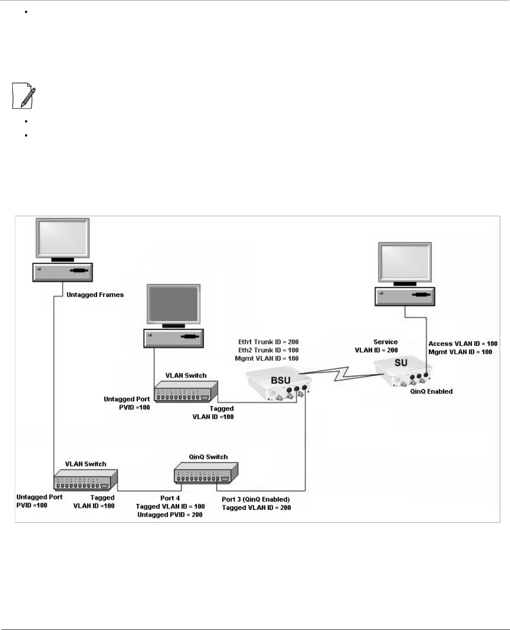
QinQ
Tsunami® 800 & 8000 Series - Software Management Guide 314
Device Management
– From the BSU Ethernet side, the BSU/SU can be managed with a single VLAN tagged packet that matches the
Management VLAN ID.
– From the SU Ethernet side, only SU can be managed with a single VLAN tagged packet that matches the
Management VLAN ID; BSU cannot be managed from the SU Ethernet side.
:
In a QuickBridge link, Q-in-Q should be enabled either on an End Point A or an End Point B.
The user configurable TPID is only used in the Service Provider VLAN tag. The Inner or customer VLAN tag should
always have TPID as 0x8100.
An Example:
The following diagram is the pictorial representation of how traffic flows in a QinQ enabled network.
The Computer behind SU can be used to manage the SU.
To manage BSU, connect another Computer to BSU Ethernet port through a VLAN switch with PVID as 100.
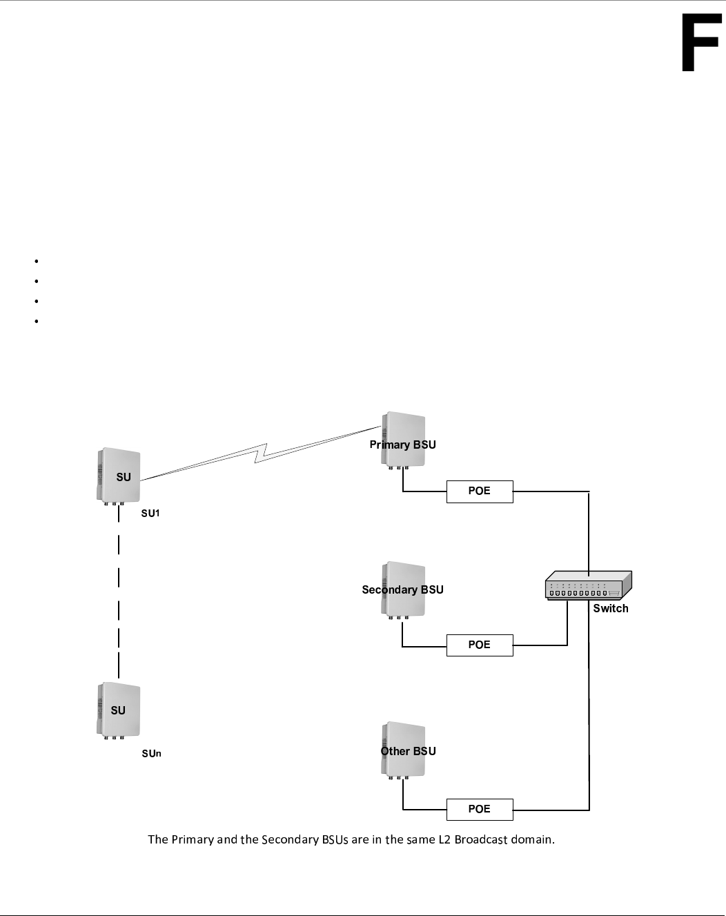
Tsunami® 800 & 8000 Series - Software Management Guide 315
BSU Redundancy
The BSU Redundancy feature can help in reducing the network outage in case of the Primary BSU failure. This feature
enables the SU to keep track of the Primary and the Secondary BSU availability through a proprietary protocol. This allows
the SU to switch between the Primary and the Secondary BSU depending on the link status. If both the Primary and the
Secondary BSU are not available, the SU attempts to find any other BSU within its network.
Configuration Guidelines
This feature is activated only on a SU. By default, it is disabled.
Use a non-empty string to enable this feature and an empty string to disable this feature.
When this feature is enabled, it is mandatory to configure both the Primary and the Secondary BSU name on the SU.
The Primary and the Secondary BSU names should be unique.
It is expected that the Primary and the Secondary BSUs are connected to the same L2 Broadcast domain and are
configured with the same “Network Name” as the SU.
Example
Figure F-1 An Example - BSU Redundancy Feature

BSU Redundancy
Tsunami® 800 & 8000 Series - Software Management Guide 316
Log Samples for BSU Redundancy
SU - During Boot Up
Channel 160 is set as the current channel.
SU is trying to register with BSU: BSU1 (MAC: 00:0b:6b:b7:4c:26).
SU received QoS Class: Unlimited Best Effort (indx: 1).
SU registered with BSU: BSU1 (MAC: 00:0b:6b:b7:4c:26) on channel 160(0x14004A0) (SNR: A1:46 A2:0 A3:40[dB]) at
WORP port[ 0 ].
Link Profile Index: 1.
Wireless: WORP Link Established with Primary BSU: BSU1
Wireless: SU discovered Secondary BSU:BSU2 on channel:60
After getting connected to the Primary BSU, the SU should discover the secondary BSU.
Primary BSU Down - Connected to Secondary BSU
SU unregistered from BSU: BSU1 (MAC: 00:0b:6b:b7:4c:26).
Channel 60 is set as the current channel.
SU is trying to register with BSU: BSU2 (MAC: 00:0b:6b:b7:4b:ff).
SU received QoS Class: Unlimited Best Effort (indx: 1).
SU registered with BSU: BSU2 (MAC: 00:0b:6b:b7:4b:ff) on channel 60(0x78043C) (SNR: A1:51 A2:0 A3:49[dB]) at
WORP port[ 0 ].
kernel:Worp: Link Profile Index: 1.
Wireless: WORP Link Established with Secondary BSU: BSU2
Connected to Other BSU
01:52:25 kernel:Worp: WARNING: Channel 100 is set as the current channel.
01:52:25 kernel:Worp: SU is trying to register with BSU: BSU3 (MAC: 00:20:a6:d3:ed:e5).
01:52:25 kernel:Worp: SU received QoS Class: Unlimited Best Effort (index: 1).
01:52:25 kernel:Worp: SU registered with BSU: BSU3 (MAC: 00:20:a6:d3:ed:e5) on channel 100(0xC80464) (SNR:
A1:58 A2:0 A3:54[dB]) at WORP port[ 0 ].
01:52:25 kernel:Worp: Link Profile Index: 1.
01:52:25: Wireless: WORP Link Established with Other BSU: BSU3
01:54:35: Wireless: SU discovered Secondary BSU:BSU2 on channel:60
01:54:35: Wireless: SU discovered Primary BSU:BSU1 on channel:160
SU should discover both the Primary and the Secondary BSU, and connect to the Primary BSU after the switch time
interval.
BSU Switch Time Interval - 15 Minutes
1Wireless: WORP Link Established with Secondary BSU: BSU2
00:08:34: Wireless: SU discovered Primary BSU:BSU1 on channel:160
00:23:34 kernel:Worp: SU unregistered from BSU: BSU2 (MAC: 00:0b:6b:b7:4b:ff).
00:23:34 kernel:Worp: WARNING: Channel 0 is set as the current channel.
00:23:35 kernel:Worp: SU is trying to register with BSU: BSU1 (MAC: 00:0b:6b:b7:4c:26).
00:23:35 kernel:Worp: SU received QoS Class: Unlimited Best Effort (indx: 1).

BSU Redundancy
Tsunami® 800 & 8000 Series - Software Management Guide 317
00:23:35 kernel:Worp: SU registered with BSU: BSU1 (MAC: 00:0b:6b:b7:4c:26) on channel 160(0x14004A0) (SNR:
A1:43 A2:0 A3:36[dB]) at WORP port[ 0 ].
00:23:35 kernel:Worp: Link Profile Index: 1.
00:23:35: Wireless: WORP Link Established with Primary BSU: BSU1
00:24:34: Wireless: SU discovered Secondary BSU:BSU2 on channel:60
Connect to Primary BSU
01:59:25: Wireless: WORP Link Established with Other BSU: BSU3
02:02:25 kernel:Worp: SU unregistered from BSU: BSU3 (MAC: 00:20:a6:d3:ed:e5)..
02:02:25: Wireless: SU discovered Secondary BSU:BSU2 on channel:60
02:02:25: Wireless: SU discovered Primary BSU:BSU1 on channel:160
02:02:25 kernel:Worp: SU is trying to register with BSU: BSU2 (MAC: 00:0b:6b:b7:4b:ff).
02:02:25 kernel:Worp: SU received QoS Class: Unlimited Best Effort (indx: 1).
02:02:25 kernel:Worp: SU registered with BSU: BSU2 (MAC: 00:0b:6b:b7:4b:ff) on channel 60(0x78043C) (SNR:
A1:37 A2:0 A3:35[dB]) at WORP port[ 0 ].
02:02:25: Wireless: WORP Link Established with Secondary BSU: BSU2
02:04:25 kernel:Worp: SU unregistered from BSU: BSU2 (MAC: 00:0b:6b:b7:4b:ff).
02:04:25 kernel:Worp: SU is trying to register with BSU: BSU1 (MAC: 00:0b:6b:b7:4c:26).
02:04:25 kernel:Worp: SU registered with BSU: BSU1 (MAC: 00:0b:6b:b7:4c:26) on channel 160(0x14004A0)
(SNR: A1:46 A2:0 A3:42[dB]) at WORP port[ 0 ].
02:05:25: Wireless: SU discovered Secondary BSU:BSU2 on channel:60
02:04:25: Wireless: WORP Link Established with Primary BSU: BSU1
No Response Message
03:32:25 kernel:Worp: WARNING: Channel 0 is set as the current channel.
03:32:25 kernel:Worp: SU is trying to register with BSU: BSU1 (MAC: 00:0b:6b:b7:4c:26).
03:32:25 kernel:Worp: SU received QoS Class: Unlimited Best Effort (indx: 1).
03:32:25 kernel:Worp: SU registered with BSU: BSU1 (MAC: 00:0b:6b:b7:4c:26) on channel 160(0x14004A0) (SNR:
A1:45 A2:0 A3:42[dB]) at WORP port[ 0 ].
03:32:25 kernel:Worp: Link Profile Index: 1.
03:32:25: Wireless: WORP Link Established with Primary BSU: BSU1
03:33:25: Wireless: SU discovered Secondary BSU:BSU2 on channel:60
03:40:43: Wireless: Secondary BSU: BSU2 not Available

Tsunami® 800 & 8000 Series - Software Management Guide 318
Bootloader CLI and ScanTool
Bootloader CLI
The Bootloader CLI is a minimal subset of the normal CLI that is used to perform initial configuration of the device. The
Bootloader CLI is available when the device embedded software is not running.
This interface is only accessible through the serial interface, if:
The device does not contain a software image
An existing image is corrupted
An automatic (default) download of image over TFTP has failed
The Bootloader CLI provides the ability to configure the initial setup parameters; and depending on this configuration, a
software file is downloaded to the device during startup.
The Bootloader CLI supports the following commands:
: Restore the factory settings
: Print Online Help
: Reboot the device
: Set the parameters
: Show the parameters
The Bootloader CLI supports the following parameters (for viewing and modifying):
: IP Address
: System Name
: Gateway IP Address
: Server IP Address
: IP Address Type
: Net Mask
: Image file name (including the file extension)
If the Bootloader fails to load the firmware from flash, it tries to get the firmware from the network. While trying to get
firmware from the network, the device should be powered on using Ethernet 1 interface of the device. The default
configuration of the Bootloader parameters are as follows:
Parameter Value
ipaddr 169.254.128.132
netmask 255.255.255.0
gatewayip 169.254.128.132
systemname systemname
serverip 169.254.128.133
filename imagename
ipaddrtype dynamic
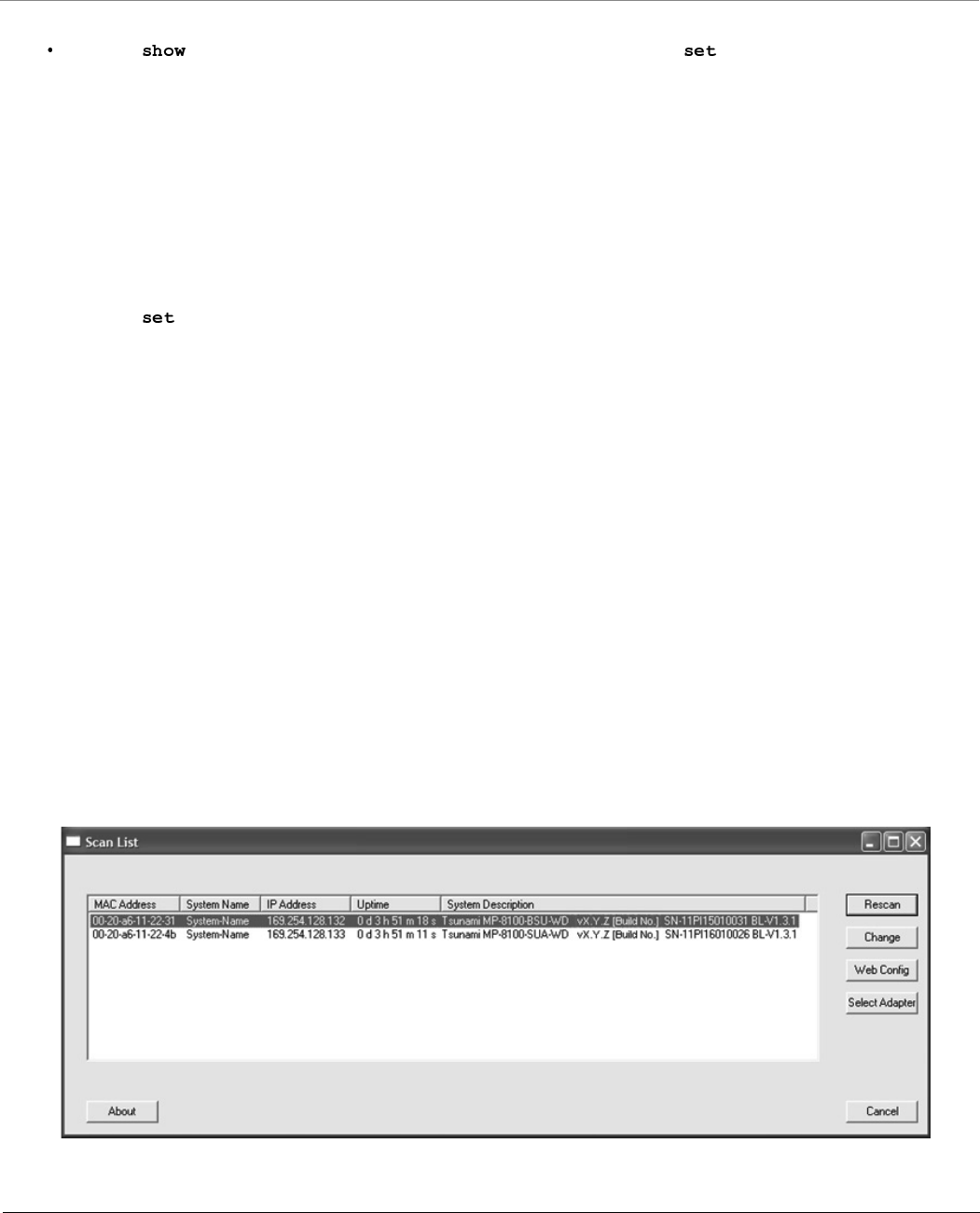
Bootloader CLI and ScanTool
Tsunami® 800 & 8000 Series - Software Management Guide 319
To Load the Firmware from the Network
Use the command to view the parameters and their values, and use the command to set the parameter
value.
To Load the Firmware by using Dynamic IP Parameters
1. Set the ipaddrtype to dynamic
2. Run the BOOTP and TFTP Servers followed by device reboot
When the device reboots, the device gets the IP Address and Boot filename from the BOOTP server. You need not change any
of the default Bootloader parameters. After BOOTP succeeds, the device initiates a TFTP request with the filename it gets
from BOOTP.
To Load the Firmware by using Static IP Parameters
1. Use the command to set the IP parameters like ‘ipaddr’, ‘serverip’, ‘filename’ and also set the parameter
‘ipaddrtype’ to static.
2. Run the TFTP Server followed by device reboot.
When the device reboots, the TFTP request is initiated with the value taken from the parameter “filename”. This request is
sent to the IP address set as “serverip”. In this case, the TFTP Server should be reachable to the device.
ScanTool
If you want to access the device with ScanTool, then the host running the ScanTool should also be in the same network as the
device. The ScanTool broadcast requests are discarded by the routers if the device and the host running the ScanTool are in
different network. This means that the ScanTool cannot discover the device.
A device in Bootloader can be recognized by looking at the system description. If the system description does not contain any
build number in braces, conclude that the device is in Bootloader mode.
For example:
MP-8100-BSU-WD - Description of the device
vX.Y.Z - Firmware Version
SN-11Pl15010031 - Serial Number
BL-v1.3.1 - Bootloader version
Figure G-1 Scan Tool View of a Device in Bootloader Mode (An Example)

Tsunami® 800 & 8000 Series - Software Management Guide 320
SNR Information
Given below are the SNR values for the following devices:
MP-8100-BSU
MP-8100-SUA
MP-8150-SUR
MP-8150-SUR-100
QB-8100-EPA/LNK
QB-8150-EPR/LNK
QB-8150-LNK-100
QB-8151-EPR/LNK
MCS
Index Modulation
No
of
Streams
2.4 GHz
5 MHz 10 MHz 20 MHz 40 MHz
Data
Rate
Min
SNR
Max
SNR
Data
Rate
Min
SNR
Max
SNR
Data
Rate
Min
SNR
Max
SNR
Data Rate Min
SNR
Max
SNR
Full Short
MCS0 BPSK 1/2 Single 1.6 10 86 3.3 10 86 6.5 12 86 13.5 15 26 80
MCS1 QPSK 1/2 Single 3.3 15 86 6.5 16 86 13 21 86 27 30 26 80
MCS2 QPSK 3/4 Single 4.9 21 84 9.7 21 84 19.5 21 84 40.5 45 26 79
MCS3 16 QAM 1/2 Single 6.5 23 82 13 23 82 26 23 82 54 60 30 77
MCS4 16 QAM 3/4 Single 9.7 26 80 19.5 26 80 39 25 80 81 90 33 77
MCS5 64 QAM 2/3 Single 13 29 79 26 29 79 52 27 78 108 120 37 76
MCS6 64 QAM 3/4 Single 14.6 30 79 29.3 31 78 58.5 30 77 121.5 135 40 75
MCS7 64 QAM 5/6 Single 16.2 32 78 32.5 32 78 65 32 77 135 150 42 75
MCS8 BPSK 1/2 Dual 3.3 12 86 6.5 14 86 13 14 86 27 30 16 80
MCS9 QPSK 1/2 Dual 6.5 20 84 13 21 84 26 21 84 54 60 26 80
MCS10 QPSK 3/4 Dual 9.7 22 82 19.5 23 82 39 22 82 81 90 28 79
MCS11 16 QAM 1/2 Dual 13 23 80 26 23 80 52 24 80 108 120 32 77
MCS12 16 QAM 3/4 Dual 19.5 27 80 39 27 80 78 30 78 162 180 35 77
MCS13 64 QAM 2/3 Dual 26 30 79 52 30 79 104 34 78 216 240 37 76
MCS14 64 QAM 3/4 Dual 29.3 36 78 58.5 35 77 117 37 77 243 270 43 75
MCS15 64 QAM 5/6 Dual 32.5 39 78 65 38 77 130 39 76 270 300 45 75

SNR Information
Tsunami® 800 & 8000 Series - Software Management Guide 321
Given below are the SNR values for the following device(s) in legacy mode:
MP-8100-BSU
MP-8100-SUA
MP-8150-SUR
MP-8150-SUR-100
MCS
Index Modulation
No
of
Streams
5 GHz
5 MHz 10 MHz 20 MHz 40 MHz
Data
Rate
Min
SNR
Max
SNR
Data
Rate
Min
SNR
Max
SNR
Data
Rate
Min
SNR
Max
SNR
Data Rate Min
SNR
Max
SNR
Full Short
MCS0 BPSK 1/2 Single 1.6 6 86 3.3 7 86 6.5 6 86 13.5 15 9 80
MCS1 QPSK 1/2 Single 3.3 8 86 6.5 8 86 13 9 86 27 30 11 80
MCS2 QPSK 3/4 Single 4.9 10 84 9.7 13 84 19.5 11 84 40.5 45 15 79
MCS3 16 QAM 1/2 Single 6.5 14 82 13 16 82 26 14 82 54 60 16 77
MCS4 16 QAM 3/4 Single 9.7 17 80 19.5 20 80 39 18 80 81 90 20 77
MCS5 64 QAM 2/3 Single 13 22 79 26 24 79 52 22 78 108 120 24 76
MCS6 64 QAM 3/4 Single 14.6 25 79 29.3 26 78 58.5 25 77 121.5 135 27 75
MCS7 64 QAM 5/6 Single 16.2 28 78 32.5 29 78 65 28 77 135 150 30 75
MCS8 BPSK 1/2 Dual 3.3 8 86 6.5 9 86 13 9 86 27 30 9 80
MCS9 QPSK 1/2 Dual 6.5 12 84 13 12 84 26 12 84 54 60 13 80
MCS10 QPSK 3/4 Dual 9.7 14 82 19.5 15 82 39 14 82 81 90 17 79
MCS11 16 QAM 1/2 Dual 13 16 80 26 16 80 52 16 80 108 120 22 77
MCS12 16 QAM 3/4 Dual 19.5 20 80 39 21 80 78 20 78 162 180 25 77
MCS13 64 QAM 2/3 Dual 26 25 79 52 26 79 104 26 78 216 240 27 76
MCS14 64 QAM 3/4 Dual 29.3 29 78 58.5 29 77 117 29 77 243 270 30 75
MCS15 64 QAM 5/6 Dual 32.5 30 78 65 30 77 130 30 76 270 300 33 75
Modulation
2.4 GHz 5 GHz
5 MHz 10 MHz 20 MHz 5 MHz 10 MHz 20 MHz
Data
Rate
Min
SNR
Max
SNR
Data
Rate
Min
SNR
Max
SNR
Data
Rate
Min
SNR
Max
SNR
Min
SNR
Max
SNR
Min
SNR
Max
SNR
Min
SNR
Max
SNR
BPSK 1/2 1.5 10 84 3 10 84 6 13 84 8 84 8 84 7 81
BPSK 3/4 2.25 10 84 4.5 11 84 9 13 84 9 84 9 84 8 81
QPSK 1/2 3 12 84 6 11 84 12 15 84 10 82 10 82 9 81
QPSK 3/4 4.5 14 84 9 13 84 18 15 84 12 82 11 82 12 81
16QAM 1/2 6 17 82 12 17 80 24 22 80 16 82 16 82 15 80
16QAM 3/4 9 20 82 18 23 78 36 25 73 18 82 18 80 18 80

SNR Information
Tsunami® 800 & 8000 Series - Software Management Guide 322
Given below are the SNR values for the following devices:
MP-8150-CPE
QB-8150-LNK-12/50
64QAM 2/3 12 27 81 24 29 76 48 28 73 24 80 24 80 24 78
64QAM 3/4 13.5 29 80 27 30 74 54 29 72 27 80 27 80 27 76
MCS
Index Modulation
No
of
Streams
5 GHz
5 MHz 10 MHz 20 MHz 40 MHz
Data
Rate
Min
SNR
Max
SNR
Data
Rate
Min
SNR
Max
SNR
Data
Rate
Min
SNR
Max
SNR
Data Rate Min
SNR
Max
SNR
Full Short
MCS0 BPSK 1/2 Single 1.6 8 82 3.3 8 82 6.5 8 82 13.5 15 8 82
MCS1 QPSK 1/2 Single 3.3 8 82 6.5 9 82 13 9 82 27 30 9 82
MCS2 QPSK 3/4 Single 4.9 10 82 9.7 11 82 19.5 11 82 40.5 45 11 80
MCS3 16 QAM 1/2 Single 6.5 13 82 13 15 82 26 17 82 54 60 16 80
MCS4 16 QAM 3/4 Single 9.7 16 82 19.5 19 82 39 19 82 81 90 18 80
MCS5 64 QAM 2/3 Single 13 20 81 26 22 81 52 23 81 108 120 23 79
MCS6 64 QAM 3/4 Single 14.6 22 80 29.3 24 80 58.5 25 80 121.5 135 24 79
MCS7 64 QAM 5/6 Single 16.2 24 80 32.5 26 80 65 26 80 135 150 26 79
MCS8 BPSK 1/2 Dual 3.3 9 82 6.5 8 82 13 9 82 27 30 9 82
MCS9 QPSK 1/2 Dual 6.5 10 82 13 10 82 26 12 82 54 60 11 80
MCS10 QPSK 3/4 Dual 9.7 12 82 19.5 12 82 39 13 82 81 90 13 80
MCS11 16 QAM 1/2 Dual 13 16 82 26 16 82 52 18 82 108 120 15 78
MCS12 16 QAM 3/4 Dual 19.5 19 80 39 20 82 78 19 82 162 180 20 68
MCS13 64 QAM 2/3 Dual 26 24 80 52 24 80 104 24 80 216 240 24 60
MCS14 64 QAM 3/4 Dual 29.3 29 80 58.5 30 78 117 27 78 243 270 29 58
MCS15 64 QAM 5/6 Dual 32.5 33 80 65 33 78 130 32 78 270 300 32 56
Modulation
2.4 GHz 5 GHz
5 MHz 10 MHz 20 MHz 5 MHz 10 MHz 20 MHz
Data
Rate
Min
SNR
Max
SNR
Data
Rate
Min
SNR
Max
SNR
Data
Rate
Min
SNR
Max
SNR
Min
SNR
Max
SNR
Min
SNR
Max
SNR
Min
SNR
Max
SNR

SNR Information
Tsunami® 800 & 8000 Series - Software Management Guide 323
Given below are the SNR values for the following device(s) in legacy mode:
MP-8150-CPE
QB-8150-LNK-12/50
Given below are the SNR values for the following devices:
MP-8160-BSU
MP-8160-BS9
MP-8160-SUA
MP-8160-CPE
Modulation
5 GHz
5 MHz 10 MHz 20 MHz
Data
Rate
Min
SNR
Max
SNR
Data
Rate
Min
SNR
Max
SNR
Data
Rate
Min
SNR
Max
SNR
BPSK 1/2 1.5 7 81 3 7 81 6 7 81
BPSK 3/4 2.25 8 81 4.5 8 81 9 8 81
QPSK 1/2 3 9 80 6 9 80 12 9 79
QPSK 3/4 4.5 12 78 9 12 78 18 12 78
16QAM 1/2 6 16 76 12 16 76 24 16 73
16QAM 3/4 9 20 72 18 20 71 36 20 71
64QAM 2/3 12 24 69 24 24 69 48 24 69
64QAM 3/4 13.5 27 68 27 27 68 54 27 66
MCS
Index Modulation
No
of
Streams
6.4 GHz
5 MHz 10 MHz 20 MHz 40 MHz
Data
Rate
Min
SNR
Max
SNR
Data
Rate
Min
SNR
Max
SNR
Data
Rate
Min
SNR
Max
SNR
Data Rate Min
SNR
Max
SNR
Full Short
MCS0 BPSK 1/2 Single 1.6 6 87 3.3 6 87 6.5 6 87 13.5 15 7 87
MCS1 QPSK 1/2 Single 3.3 8 87 6.5 8 87 13 7 87 27 30 8 86
MCS2 QPSK 3/4 Single 4.9 10 86 9.7 10 84 19.5 10 86 40.5 45 12 82
MCS3 16 QAM 1/2 Single 6.5 13 84 13 14 84 26 13 82 54 60 13 74
MCS4 16 QAM 3/4 Single 9.7 16 80 19.5 16 78 39 16 76 81 90 19 70
MCS5 64 QAM 2/3 Single 13 21 74 26 21 70 52 20 70 108 120 21 62
MCS6 64 QAM 3/4 Single 14.6 22 70 29.3 23 67 58.5 22 67 121.5 135 24 56
MCS7 64 QAM 5/6 Single 16.2 24 67 32.5 24 65 65 24 65 135 150 27 55
MCS8 BPSK 1/2 Dual 3.3 8 87 6.5 8 87 13 7 86 27 30 10 86
MCS9 QPSK 1/2 Dual 6.5 10 87 13 10 87 26 11 84 54 60 12 82
SNR Information
Tsunami® 800 & 8000 Series - Software Management Guide 324
Given below are the SNR values for the following devices:
MP-8200-BSU / SUA
MP-8250-BS9 / BS1
MP-8250-SUR
QB-8200-EPA/LNK
QB-8250-EPR/LNK
MCS10 QPSK 3/4 Dual 9.7 15 84 19.5 13 84 39 13 82 81 90 15 75
MCS11 16 QAM 1/2 Dual 13 16 80 26 17 80 52 17 78 108 120 18 74
MCS12 16 QAM 3/4 Dual 19.5 20 74 39 23 74 78 20 71 162 180 22 56
MCS13 64 QAM 2/3 Dual 26 25 70 52 24 66 104 24 65 216 240 25 55
MCS14 64 QAM 3/4 Dual 29.3 27 66 58.5 27 62 117 27 62 243 270 27 53
MCS15 64 QAM 5/6 Dual 32.5 28 64 65 29 62 130 29 62 270 300 30 52
MCS
Index Modulation
No
of
Streams
4.900 - 5.925 GHz
5 MHz 10 MHz 20 MHz 40 MHz
Data
Rate
Min
SNR
Max
SNR
Data
Rate
Min
SNR
Max
SNR
Data
Rate
Min
SNR
Max
SNR
Data Rate Min
SNR
Max
SNR
Full Short
MCS0 BPSK 1/2 Single 1.6 7 50 3.3 7 50 6.5 7 50 13.5 15 9 50
MCS1 QPSK 1/2 Single 3.3 9 50 6.5 10 50 13 11 50 27 30 10 50
MCS2 QPSK 3/4 Single 4.9 11 50 9.7 13 50 19.5 13 50 40.5 45 14 50
MCS3 16 QAM 1/2 Single 6.5 15 50 13 16 50 26 16 50 54 60 16 50
MCS4 16 QAM 3/4 Single 9.7 19 50 19.5 20 50 39 20 50 81 90 20 50
MCS5 64 QAM 2/3 Single 13 23 50 26 24 50 52 24 50 108 120 24 50
MCS6 64 QAM 3/4 Single 14.6 25 50 29.3 26 50 58.5 26 50 121.5 135 27 50
MCS7 64 QAM 5/6 Single 16.2 28 50 32.5 29 50 65 29 50 135 150 29 50
MCS8 BPSK 1/2 Dual 3.3 8 50 6.5 9 50 13 9 50 27 30 10 50
MCS9 QPSK 1/2 Dual 6.5 12 50 13 12 50 26 12 50 54 60 13 50
MCS10 QPSK 3/4 Dual 9.7 15 50 19.5 15 50 39 15 50 81 90 16 50
MCS11 16 QAM 1/2 Dual 13 18 50 26 18 50 52 18 50 108 120 20 50
MCS12 16 QAM 3/4 Dual 19.5 20 50 39 21 50 78 21 50 162 180 24 50
MCS13 64 QAM 2/3 Dual 26 25 50 52 26 50 104 26 50 216 240 27 50
MCS14 64 QAM 3/4 Dual 29.3 29 50 58.5 29 50 117 29 50 243 270 30 50
MCS
Index Modulation
No
of
Streams
6.4 GHz
5 MHz 10 MHz 20 MHz 40 MHz
Data
Rate
Min
SNR
Max
SNR
Data
Rate
Min
SNR
Max
SNR
Data
Rate
Min
SNR
Max
SNR
Data Rate Min
SNR
Max
SNR
Full Short

SNR Information
Tsunami® 800 & 8000 Series - Software Management Guide 325
Given below are the SNR values for the following device(s) in legacy mode:
MP-8200-BSU / SUA
MP-8250-BS9 / BS1
MP-8250-SUR
MCS15 64 QAM 5/6 Dual 32.5 30 50 65 30 50 130 30 50 270 300 33 50
Modulation
4.900 - 5.925 GHz
5 MHz 10 MHz 20 MHz
Data
Rate
Min
SNR
Max
SNR
Data
Rate
Min
SNR
Max
SNR
Data
Rate
Min
SNR
Max
SNR
BPSK 1/2 1.5 7 80 3 7 80 6 8 79
BPSK 3/4 2.25 8 80 4.5 9 79 9 9 77
QPSK 1/2 3 10 79 6 10 77 12 10 76
QPSK 3/4 4.5 12 78 9 12 76 18 12 74
16QAM 1/2 6 16 77 12 16 74 24 16 73
16QAM 3/4 9 20 76 18 20 72 36 21 72
64QAM 2/3 12 25 74 24 24 70 48 25 69
64QAM 3/4 13.5 27 73 27 27 68 54 27 68
MCS
Index Modulation
No
of
Streams
4.900 - 5.925 GHz
5 MHz 10 MHz 20 MHz 40 MHz
Data
Rate
Min
SNR
Max
SNR
Data
Rate
Min
SNR
Max
SNR
Data
Rate
Min
SNR
Max
SNR
Data Rate Min
SNR
Max
SNR
Full Short

SNR Information
Tsunami® 800 & 8000 Series - Software Management Guide 326
Given below are the SNR values for the following device:
MP-820-BSU-100
MP-820-SUA-50+
MP-825-SUR-50+
MP-825-CPE-50
QB-825-EPR/LNK-50
QB-825-EPR/LNK-50
MCS
Index Modulation
No
of
Streams
5 GHz
5 MHz 10 MHz 20 MHz 40 MHz
Data
Rate
Min
SNR
Max
SNR
Data
Rate
Min
SNR
Max
SNR
Data
Rate
Min
SNR
Max
SNR
Data Rate Min
SNR
Max
SNR
Full Short
MCS0 BPSK 1/2 Single 1.6 9 50 3.3 9 50 6.5 9 50 13.5 -9 50
MCS1 QPSK 1/2 Single 3.3 10 50 6.5 10 50 13 12 50 27 -11 50
MCS2 QPSK 3/4 Single 4.9 13 50 9.7 13 50 19.5 13 50 40.5 -15 50
MCS3 16 QAM 1/2 Single 6.5 17 50 13 17 50 26 16 50 54 -16 50
MCS4 16 QAM 3/4 Single 9.7 20 50 19.5 21 50 39 22 50 81 -24 50
MCS5 64 QAM 2/3 Single 13.0 24 50 26 25 50 52 25 50 108 -28 50
MCS6 64 QAM 3/4 Single 14.6 26 50 29.3 27 50 58.5 27 50 121.5 -29 50
MCS7 64 QAM 5/6 Single 16.2 30 50 32.5 29 50 65 30 50 135 -30 50
MCS8 BPSK 1/2 Dual 3.3 10 50 6.5 10 50 13 10 50 27 -10 50
MCS9 QPSK 1/2 Dual 6.5 13 50 13 12 50 26 12 50 54 -13 50
MCS10 QPSK 3/4 Dual 9.7 15 50 19.5 16 50 39 15 50 81 -17 50
MCS11 16 QAM 1/2 Dual 13.0 18 50 26 19 50 52 17 50 108 -22 50
MCS12 16 QAM 3/4 Dual 19.5 23 50 39 23 50 78 23 50 162 -25 50
MCS13 64 QAM 2/3 Dual 26.0 27 50 52 26 50 104 27 50 216 -27 50
MCS14 64 QAM 3/4 Dual 29.3 29 50 58.5 29 50 117 30 50 243 -30 50
MCS15 64 QAM 5/6 Dual 32.5 31 50 65 30 50 130 31 50 270 -33 50

SNR Information
Tsunami® 800 & 8000 Series - Software Management Guide 327
Given below are the SNR values for the following device in legacy mode:
MP-820-BSU-100
MP-820-SUA-50+
MP-825-CPE-50
MP-825-SUR-50+
Modulation
5 GHz
10 MHz 20 MHz
Data
Rate
Min
SNR
Max
SNR
Data
Rate
Min
SNR
Max
SNR
BPSK 1/2 3 8 50 6 8 50
BPSK 3/4 4.5 9 50 9 9 50
QPSK 1/2 6 11 50 12 12 50
QPSK 3/4 9 12 50 18 13 50
16QAM 1/2 12 16 50 24 16 50
16QAM 3/4 18 21 50 36 21 50
64QAM 2/3 24 24 50 48 25 50
64QAM 3/4 27 28 50 54 28 50

Tsunami® 800 & 8000 Series - Software Management Guide 328
Configuration File Cross-loading across the
Products
Proxim portfolio comprises different product lines and SKUs which differ in features and capabilities depending on the
hardware platform and the country setting or licensing used in them. This document describes the process to successfully
apply the configuration file on a device(s) and the software checks run while applying the configuration file on a device(s).
The user can apply a configuration file retrieved from a (Source) device to another compatible (Target) device. In order to
successfully apply the configuration file, the following criteria should be met.
1. The Hardware Inventory Component ID should be same for both the source device and the target device.
The configuration file can be applied only to the devices of the same family.
The configuration file retrieved from an 8xx series device cannot be applied to a device from 81xx series.
The configuration file of a MP-8160-BSU/MP-8160-SUA device cannot be applied to an 8100/8200 series device
and vice versa even though they share the same component ID.
The configuration file of a MP-8150-CPE device cannot be applied to a MP-8160-CPE device and vice versa even
though they share the same component ID.
2. The Regulatory Domain should be same in both the source device and the target device.The available Regulatory
Domains are listed below:
WD SKU is compatible only with the EU SKU. For example, if the configuration file retrieved from a WD SKU
device is loaded on a US or JP SKU target device then the upgrade fails.
If the above criteria are met, the configuration file can be successfully applied on the target device else an error message is
thrown. Once the configuration file is loaded and the device is rebooted, the software tries to apply the new configuration
file during the system boot-up process.
Hardware Inventory Component ID Products
2000 AP-800; AP-8000
2001 MP-8100-BSU; MP-8100-SUA; MP-8150-SUR
MP-8150-SUR-100
MP-8160-BSU; MP-8160-SUA; MP-8160-BS9
MP-8200-BSU; MP-8200-SUA; MP-8250-BS9/SUR
QB-8xxx-EPA; QB-8xxx-EPR;
2003 MP-8150-CPE
2005 Tsunami 82x Series
2006 AP-8100

Configuration File Cross-loading across the Products
Tsunami® 800 & 8000 Series - Software Management Guide 329
Sometimes, a device from a particular product series may have different a license information compared to other devices of
the same series. Therefore, the start-up process validates the configuration file against the license file of the device before
applying the configuration file. The configuration file is valid, if the following conditions are met:
1. The input bandwidth limit in the configuration file should be less than or equal to the input bandwidth limit in the
license file.
2. The output bandwidth limit in the configuration file should be less than or equal to the output bandwidth limit in the
license file.
3. The sum of the input and output bandwidth limit in the configuration file should be less than or equal to the
cumulative bandwidth limit in the license file.
4. The frequency band (2.4, 4.9, and 5 G Hz) in the configuration file should match with any one of the supported
frequency bands in the license file.
5. The radio operation mode (BSU/SU/AP) in the configuration file should match with any one of supported radio
operating modes in the license file.
6. The number of satellites in the configuration file should be less than or equal to the number of satellites in the license
file.
7. The product family (TMP/TQB/AP) value in the configuration file should match the product family value in the license
file.
8. Tx/Rx antenna chain mask in the configuration file should match the Tx/Rx antenna chain mask in the license file.
If any one of the above conditions is not met, the configuration file will be removed by the flash control module
during initialization and the device will boot-up with the last known good configuration. Before deleting the
configuration file, an eventlog is generated about the violation of the license parameters. In some cases, if the
last known good configuration does not exist internally, the device can reset the configuration to factory
defaults and boot up.

Tsunami® 800 & 8000 Series - Software Management Guide 330
Abbreviations
A
ACL Access Control List
ACS Automatic Channel Selection
AES Advanced Encryption Standard
ALG Application Level Gateway
ARP Address Resolution Protocol
ATPC Adaptive Transmit Power Control
B
BSU Base Station Unit
C
CCP Compression Control Protocol
CHAP Challenge Handshake Authentication Protocol
CLI Command Line Interface
CIR Committed Information Rate
CPE Customer Premises Equipment
CRC Cyclic Redundancy Check
D
DDRS Dynamic Data Rate Selection
DES Data Encryption Standard
DFS Dynamic Frequency Selection
DHCP Dynamic Host Configuration Protocol
DNS Domain Name System
DSL Digital Subscriber Line
E
EIRP Equivalent Isotropically Radiated Power
EOL End of Life
ETSI European Telecommunications Standards Institute
F
FCC Federal Communications Commission

Abbreviations
Tsunami® 800 & 8000 Series - Software Management Guide 331
FCS Frame Check Sequence
G
Gbps Gigabit Per Second
GPL General Public License
GRE Generic Routing Encapsulation
H
HTTP HyperText Transfer Protocol
HTTPS HyperText Transfer Protocol Secure
I
IANA Internet Assigned Numbers Authority (IANA)
IC Industry Canada
ICMP Internet Control Message Protocol
IGMP Internet Group Management Protocol
ISP Internet Service Provider
ITS Intelligent Transportation System
L
LACP Link Aggregation Control Protocol
LAN Local Area Network
LCP Link Configuration Protocol
LED Light Emitting Diode
LGPL Lesser General Public License
M
MAN Metropolitan Area Networks
Mbps Megabits Per Second
MD5 Message-Digest algorithm
MIB Management Information Base
MIMO Multiple-input and multiple-output
MIR Maximum Information Rate
MP Multipoint
MPPE Microsoft Point-to-Point Encryption
MSCHAP v2 Microsoft Challenge-Handshake Authentication Protocol
MTU Maximum Transmission Unit

Abbreviations
Tsunami® 800 & 8000 Series - Software Management Guide 332
N
NAPT Network Address Port Translation
NAT Network Address Translation
NCP Network Control Protocol
NBD Next Business Day
NMS Network Management System
NOP Non Occupancy Period
P
PAP Password Authentication Protocol
PC Personal Computer
PoE Power Over Ethernet
PPPoE Point-to-point Protocol over Ethernet
PTMP Point-to-multipoint
PTP Point-to-point
PVES ProximVision ES
Q
QB QuickBridge
QoS Quality of Service
R
RADIUS Remote Authentication Dial In User Service
RAS Remote Access Services
RF Radio Frequency
RIP Routing Information Protocol
RMA Return Material Authorization
RLT Radio Link Test
RSSI Received Signal Strength Indicator
S
SHA Secure Hash Algorithm
SKU Stock Keeping Unit
SNMP Simple Network Management Protocol
SNR Signal-to-noise Ratio
SNTP Simple Network Time Protocol
SSH Secure Shell

Abbreviations
Tsunami® 800 & 8000 Series - Software Management Guide 333
SSL Secure Socket Layer
STP Spanning Tree Protocol
SU Subscriber Unit
T
TBC Text Based Configuration
TCP Transmission Control Protocol
TFTP Trivial File Transfer Protocol
TKIP Temporal Key Integrity Protocol
TPC Transmit Power Control
TPID Tag Protocol Identifier
TTL Time to Live
U
UDP User Datagram Protocol
UTP Unshielded Twisted Pair
V
VLAN Virtual Local Area Network
W
WEP Wired Equivalent Privacy
WORP Wireless Outdoor Router Protocol

Tsunami® 800 & 8000 Series - Software Management Guide 334
Lightning Protection
Lightning protection is used to maximize the reliability of the communications equipment by safely re-directing current from
a lightning strike or a power surge traveling along the Cat 5/Cat5e/Cat 6 Ethernet cabling to the ground using the shortest
path possible. Designing a proper grounding system prior to installing any communications equipment is critical to minimize
the possibility of equipment damage, void warranties, and cause serious injury.
The surge arrestor (sometimes referred to as a lightning protector) can protect your sensitive electronic equipment from
high-voltage surges caused by discharges and transients at the PoE.
Proxim Wireless offers superior lightning and surge protection for Tsunami® series products. Contact your reseller or
distributor for more information.

Tsunami® 800 and 8000 Series - Software Management Guide 335
Statement of Warranty
Warranty Coverage
Proxim Wireless Corporation warrants that its products are manufactured solely from new parts, conform substantially to
specifications, and will be free of defects in material and workmanship for a Warranty Period of 1 year from the date of
purchase.
Repair or Replacement
When Proxim determines that a returned product does not meet the warranted criteria during the warranty period, Proxim at
its option, will either: (a) repair the defective product; (b) replace the defective product with a new or refurbished product
that is at least equivalent to the original; or (c) refund the price paid for the defective product. Generally, products are
repaired or replaced within thirty (30) business days of receipt of the product at a Proxim Logistical/Repair Center. The
warranty period for repaired or replacement products is ninety (90) days or the remainder of the original warranty period,
whichever is longer. These three alternatives constitute the customer’s sole and exclusive remedy and Proxim’s sole and
exclusive liability under warranty provisions.
Limitations of Warranty
Proxim’s warranties do not apply to any product (hardware or software) which has (a) been subjected to abuse, misuse,
neglect, accident, or mishandling, (b) been opened, repaired, modified, or altered by anyone other than Proxim, (c) been
used for or subjected to applications, environments, or physical or electrical stress or conditions other than as intended and
recommended by Proxim, (d) been improperly stored, transported, installed, or used, or (e) had its serial number or other
identification markings altered or removed.
Buyers can contact Proxim Wireless Customer Service Center either by telephone or via web. Support and repair of products
that are out of warranty will be subject to a fee. Contact information is shown below. Additional support information can be
found at Proxim Wireless’s web site at .
Contact technical support via telephone as follows:
USA and Canada Customers
Phone: +1-408-383-7700; +1-866-674-6626
Business Hours: 24x7 live response. Tier 3 support: 8 a.m. to 5 p.m. M-F PDT (UTC/GMT -7 hrs)
International Customers
Phone: +1-408-383-7700; 0800-916475 (France); 8-800-100-9485 (Russia)
Business Hours: 24x7 live response. Tier 3 support: 8 a.m. to 5 p.m. M-F PDT (UTC/GMT -7 hrs)
General Procedures
When contacting the Customer Service for support, Buyer should be prepared to provide the product description and serial
number and a description of the problem. The serial number should be on the product.
In the event the Customer Service Center determines that the problem can be corrected with a software update, Buyer might
be instructed to download the update from Proxim Wireless’s web site or, if that’s not possible, the update will be sent to
Buyer. In the event the Customer Service Center instructs Buyer to return the product to Proxim Wireless for repair or
replacement, the Customer Service Center will provide Buyer a Return Material Authorization (“RMA”) number and shipping
instructions. Buyer must return the defective product to Proxim Wireless, properly packaged to prevent damage, shipping
prepaid, with the RMA number prominently displayed on the outside of the container.

Statement of Warranty
Tsunami® 800 and 8000 Series - Software Management Guide 336
Calls to the Customer Service Center for reasons other than product failure will not be accepted unless Buyer has purchased a
Proxim Wireless Service Contract or the call is made within the warranty period. After the warranty period, Technical Support
is fee based (detailed in ).
If Proxim Wireless reasonably determines that a returned product is not defective or is not covered by the terms of this
Warranty, Buyer shall be charged a service charge and return shipping charges.
Other Information
Search Knowledgebase
Proxim Wireless stores all resolved problems in a solution database at the following URL: .
Create a Support Request
Submit a question or open an issue to Proxim Wireless technical support staff at the following URL:
.

Tsunami® 800 and 8000 Series - Software Management Guide 337
Technical Services and Support
Obtaining Technical Service and Support
If you are having trouble using the Proxim product, please read this guide and the additional documentation provided with
your product. If you require additional support to resolve your issue, please be ready to provide the following information
before you contact Proxim’s Technical Services team:
Product information
– Part number and serial number of the suspected faulty device
Trouble/error information
– Trouble/symptom being experienced
– Activities completed to confirm fault
– Network information (What kind of network are you using?)
– Circumstances that preceded or led up to the error
– Message or alarms viewed
– Steps taken to reproduce the problem
ServPak information (if a Servpak customer):
– ServPak account number
Registration information
– If the product is not registered, date and location where you purchased the product
: Technical Support is free for the warranty period from the date of purchase.
Support Options
Proxim eService Web Site Support
The Proxim eService Web site is available 7x24x365 at .
On the Proxim eService Web Site, you can access the following services:
Product Download Page: Provides quick links to product firmware, software, and documentation downloads.
Proxim TV Links: A link to helpful video tutorials.
Knowledgebase: A solution database of all the resolved problems. You can search by product, category, keywords,
or phrases.
Live Chat: Chat with a support technician on-line or request to call back at a later time.
Create a Support Request: Create a support request with our technical support staff who will reply to you by email.
Case Management: Login to check the status of your support cases, update your personal profile, or access
restricted information and features.
Provide Feedback: Submit a suggestion, complaint, or other feedback about the support site and our products.
Technical Services and Support
Tsunami® 800 and 8000 Series - Software Management Guide 338
Telephone Support
Contact technical support via telephone as follows:
USA and Canada Customers
—Phone: +1-408-383-7700; +1-866-674-6626
—Business Hours: 24x7 live response. Tier 3 support: 8 a.m. to 5 p.m. M-F PDT (UTC/GMT -7 hrs)
International Customers
—Phone: +1-408-383-7700; 0800-916475 (France); 8-800-100-9485 (Russia)
—Business Hours: 24x7 live response. Tier 3 support: 8 a.m. to 5 p.m. M-F PDT (UTC/GMT -7 hrs)
ServPak Support
To provide even greater investment protection, Proxim Wireless offers a cost-effective support program called ServPak.
ServPak is a program of enhanced service support options that can be purchased as a bundle or individually, tailored to meet
your specific needs. Whether your requirement is round the clock technical support or advance replacement service, we are
confident that the level of support provided in every service in our portfolio will exceed your expectations.
All ServPak service bundles are sold as service contracts that provide coverage for specific products from 1 to 3 years. Servpak
bundles are considered an upgrade to the standard product warranty and not an extension.
24x7 Basic Technical
Support
Basic Advanced
Replacement
(Two business days/
International economy
shipment service)
Priority Advanced
Replacement
(Next business day/
International priority
shipment service)
Priority Comprehensive
Advance Replacement
(Next business day/
International priority
shipment service)
8x7 Advanced Technical
Support
24x7 Advanced Technical
Support
24x7 Advanced Technical
Support
Software Maintenance PVES & PV NMS
Support
PVES & PV NMS
Support
Access to Knowledge
Base
Post-Installation
Optimization
50% discount on Onsite
Technical Support and
Services

Technical Services and Support
Tsunami® 800 and 8000 Series - Software Management Guide 339
Additional Information on ServPak Options
Advanced Replacement of Hardware
In the event of a hardware failure, our guaranteed turnaround time for return to factory repair is 30 days or less. Customers
who purchase this service are guaranteed replacement of refurbished or new hardware to be shipped out within one or two
business days, as applicable. Options are available for shipment services depending on the customer’s support needs.
Hardware is shipped on business days, Monday – Friday excluding Holidays, 8:00 AM – 3:30 PM Eastern Time.
Comprehensive Advanced Replacement of Hardware
In addition to ServPak Prime options, in the event of a hardware failure, Proxim will repair or replace the failed product for any
reason, other than vandalism.
7x24x365 Availability
Unlimited, direct access to technical support engineers 24 hours a day, 7 days a week, 365 days a year including Holidays.
8x5 Availability
Unlimited, direct access to world-class technical support engineers 8 hours a day, 5 days a week, Monday through Friday from
8:00AM - 5:00PM Pacific Standard Time.
Basic Technical Support
Customers who purchase this service can be rest assured that their call will be answered by Proxim’s Tier 1 technical support
and a case opened immediately to document the problem and provide initial troubleshooting to identify the solution and
resolve the incident in a timely manner.
Advanced Technical Support
In addition to Proxim’s world-class Tier 1 technical support, customers will be able to have their more complex issues escalated
to our world-class Tier 3 technical support engineers. Our Tier 3 engineers will review specific configurations to troubleshoot
intricate issues and will also provide helpful insights regarding Proxim’s products and various tips from decades of collective
experience in the wireless industry.
Software Maintenance
It's important to maintain and enhance security and performance of wireless equipment and Proxim makes this easy by
providing a Software Maintenance program that enables customers to access new feature and functionality rich software
upgrades and updates. Customers will also have full access to Proxim's vast Knowledgebase of technical bulletins, white
papers and troubleshooting documents.
Post-Installation Optimization
You can consult with our technical support engineers to enhance performance and efficiency of your network.
Post-installation optimization services include:
Review frequencies to select best possible channel
Review Modulation, Channel Bandwidth, MIMO, and WORP settings to optimize throughput and link quality
Review Satellite Density & TPC/ATPC settings
Assistance with Bandwidth controls

Technical Services and Support
Tsunami® 800 and 8000 Series - Software Management Guide 340
Assistance with QoS, RADIUS, and VLAN settings on Proxim equipment
To purchase ServPak support services, please contact your authorized Proxim distributor. To receive more information or for
questions on any of the available ServPak support options, please visit our website at
, call Proxim Support (For telephone numbers, see ) or send an
email to .
Technical Support Policy
Technical Support for Current Products during Warranty Period
All Customers are entitled to free technical support for the Proxim products they purchase from Proxim’s authorized resellers
or distributors. Technical Support is defined as communication via the Proxim Support website ( ) and/or
via telephone. This technical support will be provided for free for the entire time the product is covered by a Proxim warranty.
The term of Proxim’s warranty is determined according to the agreement under which the product was sold and generally
varies from 3 months to 2 years depending on the product. If a Customer disagrees with Proxim’s determination of warranty
duration, a request for review supported by a copy of all product purchase documentation may be submitted.
Technical Support for Current Products after Warranty Period
After the warranty period, technical support on products then being sold by Proxim will be based upon one of the following
three options Customers can choose:
Customers can choose to purchase one of Proxim’s ServPak extended warranty and enhanced support packages for
the product
Customers can choose to purchase one-time per-incident technical support for the product for a fee
Customers can choose to call the reseller or distributor who sold them the product for technical support
Tech Support on Discontinued Products
Technical Support on some products that Proxim has declared as EOL (End of Life) or otherwise is no longer selling is available
based upon one of the following three options Customers can choose:
For some discontinued products, Customers can choose to purchase one of Proxim’s EOL ServPak support packages
for the product
– No EOL ServPak support package will be available for any product discontinued more than 5 years ago
– No EOL ServPak support package is available for certain discontinued products
Customers can choose to purchase one-time per-incident technical support for the product on a per hour basis at a
rate of $125 an hour (4 hours minimum payable in advance by major credit card). This fee is payable in addition to any
RMA fee that may be charged to subsequently repair the product.
Customers can choose to call the reseller or distributor who sold them the product for technical support
All Proxim technical support for discontinued products, whether through an EOL ServPak package or otherwise, is provided
on a “best effort” basis and is subject to the continued availability of necessary components, equipment, and other technical
resources.
Note that Proxim is unable to support or warrant any equipment that has been modified, whether this modification is
physical, or if third-party software codes have been loaded onto the product.