Proxim Wireless XB92WLE 802.11 a/n PCIe Module User Manual EIRP compliance declaration revised
Proxim Wireless Corporation 802.11 a/n PCIe Module EIRP compliance declaration revised
Contents
- 1. User Manual
- 2. Software guide1
- 3. software guide2
- 4. Antenna installation guide
- 5. EIRP compliance declaration revised
- 6. HW_guide_revised
EIRP compliance declaration revised

Device installation report for FCC U-NII-1 band (5.15- 5.25GHz) compliance
The Federal Communications Commission (FCC) established new rules for the 5.15 – 5.25 GHz
U-NII-1 band in the Report and Order FCC-14-30A1, which would be effective from 2nd June,
2014. With the help of professional installation, all the Proxim devices can be configured to
comply with the power requirements set in the rules. For an angle of elevation which is above
30 degrees, the maximum EIRP limit should be set to 125mW (21 dBm). The compliance can
be achieved through proper selection of antenna, angle of installation, and Tx power control.
The appropriate selection of these parameters avoids the transmission interference between
the authorized devices of the users and also in the co-channel NGSO/MSS operations.
Proxim devices such as BSUs (Base Station Units)/ SUs (Subscriber Units) are installed by
professional installers to work in fixed outdoor configurations.
These devices are in general mounted on a tower, roof, or at a place above the street level;
therefore, it implies that all Proxim devices whether they have an external antenna or an
integrated antenna support vertical alignment to achieve downward tilt.
All devices support TPC (Transmit Power Control) configuration with a range of (0 – 21dB*)
that allows professional installers to lower the power when necessary.
Note: * Transmit power control varies with the product type and specific modulation.
The antenna/devices located at different altitudes should be tilted at the correct angle to
transmit/receive the signals effectively; thus, it optimizes the transmission and reception of
signals between the devices in the wireless network. The Figure 1.1 below shows the antenna
tilt and its importance when the successive devices are at different elevations above the
ground.
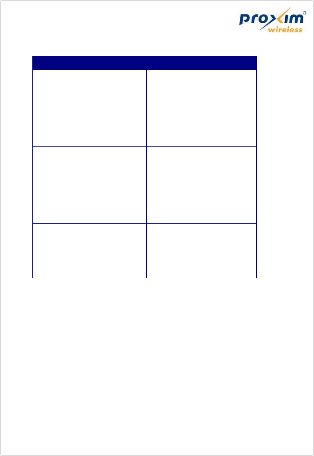
Fig 1.1 Typical installation showing device/antenna tilt angle
FCC ID
Device Models
HZB-PROXMB82
MP-8100-BSU
MP-8100-SUA
MP-8150-SUR
MP-8150-SUR-100
QB-8100-EPA/LNK
QB-8150-EPR/LNK
QB-8150-LNK-100
QB-8151-EPR/LNK
MP-8150-CPE
QB-8150-LNK-12/50
HZB-XB92WFR
HZB-XB92WLE
MP-820-BSU-100
MP-825-BS3-100
MP-820-SUA-50+
MP-820-SUA-100
MP-825-SUR-50+
MP-825-SUR-100
MP-825-CPE-50
MP-825-CPE-100
QB-825-EPR / LNK-50+
QB-825-EPR / LNK-50
HZB-MB83HP5
MP-8200-BSU
MP-8250-BS9
MP-8250-BS1
MP-8200-SUA
MP-8250-SUR
QB-8200-EPA / LNK
QB-8250-EPR / LNK
Table 1: FCC IDs for Proxim Products
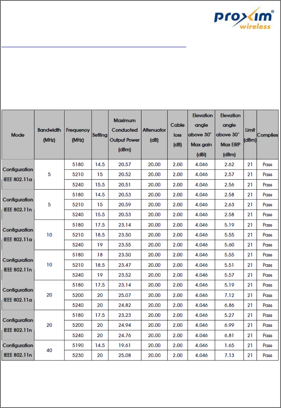
Maximum EIRP at any elevation angle greater than 300
1. FCC ID: HZB-PROXMB82
Antenna Model No: MA-WA55-30
Gain: 30dBi
Antenna Type: Panel Antenna, Linear Polarization (Vertical or Horizontal), 50 Bandwidth
Table 2: Maximum EIRP values at an angle greater than 30 deg for the Antenna model "MA-WA55-30"
with FCC ID “HZB-PROXMB82”
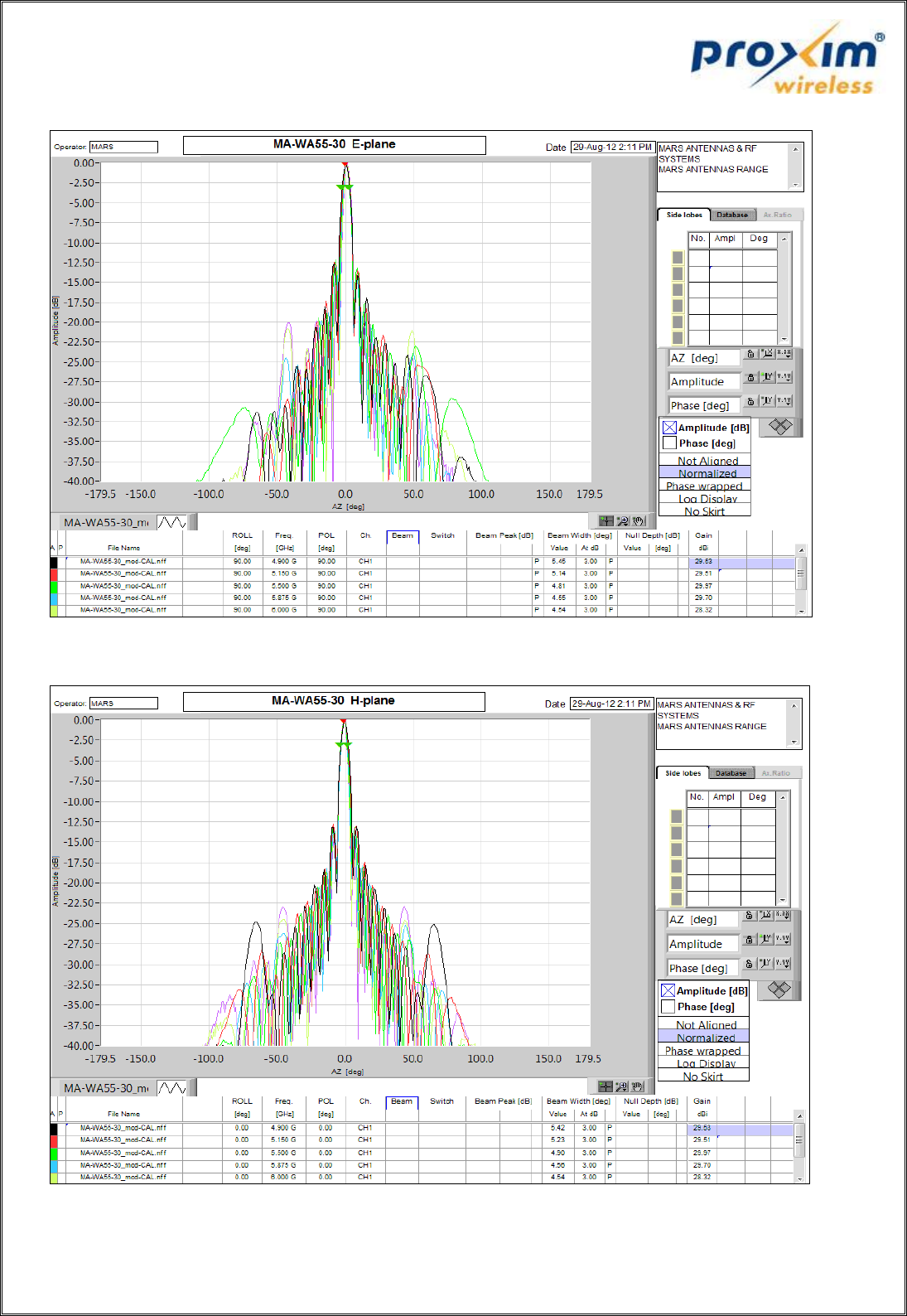
Figure 1: Radiation pattern for the Antenna Model "MA-WA55-30, E-plane"
Figure 2: Radiation pattern for the Antenna Model "MA-WA55-30, H-plane"
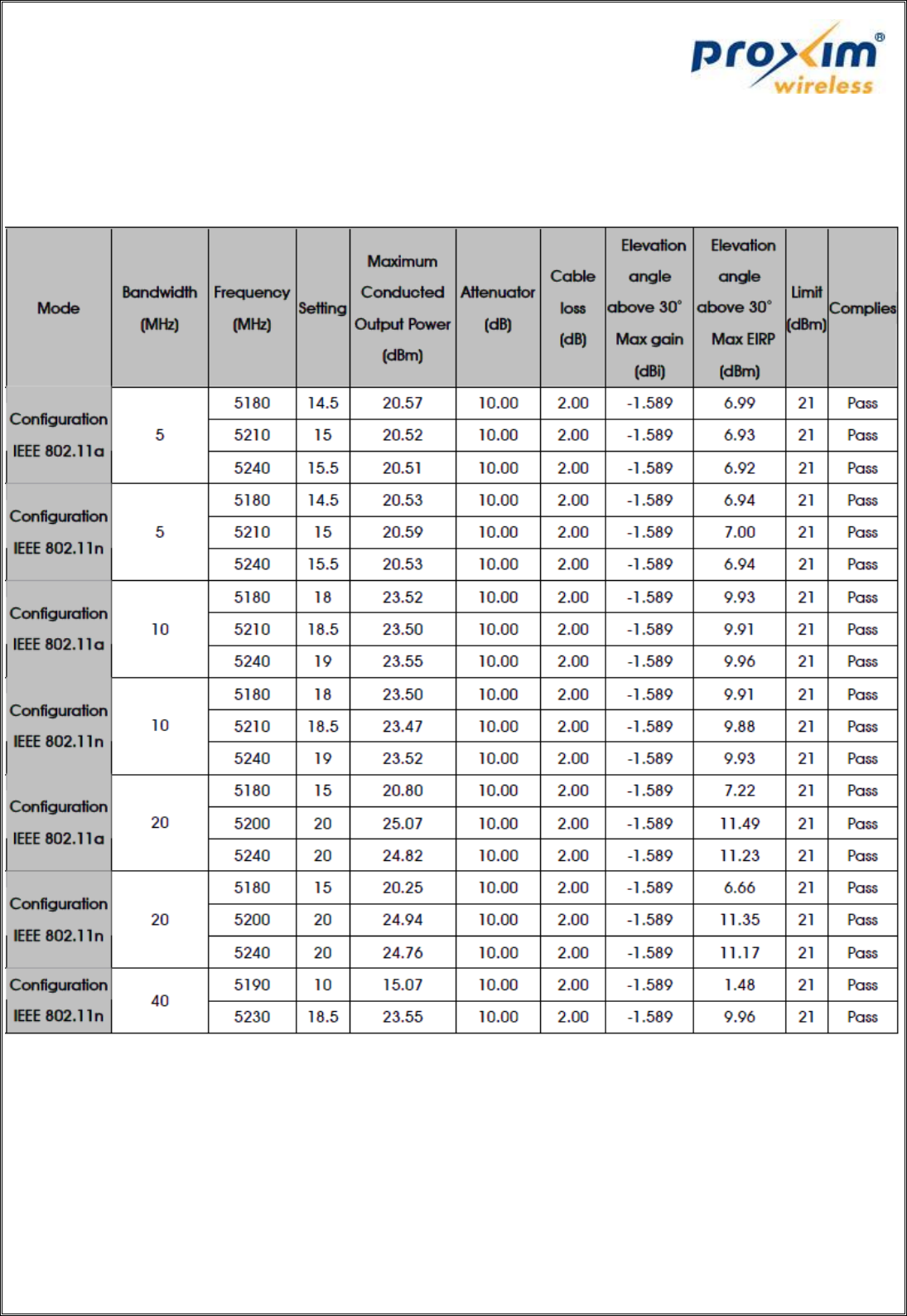
Antenna Model No: MA-WB55-20
Gain: 20dBi
Antenna Type: Sector Antenna, Linear Polarization (Vertical)
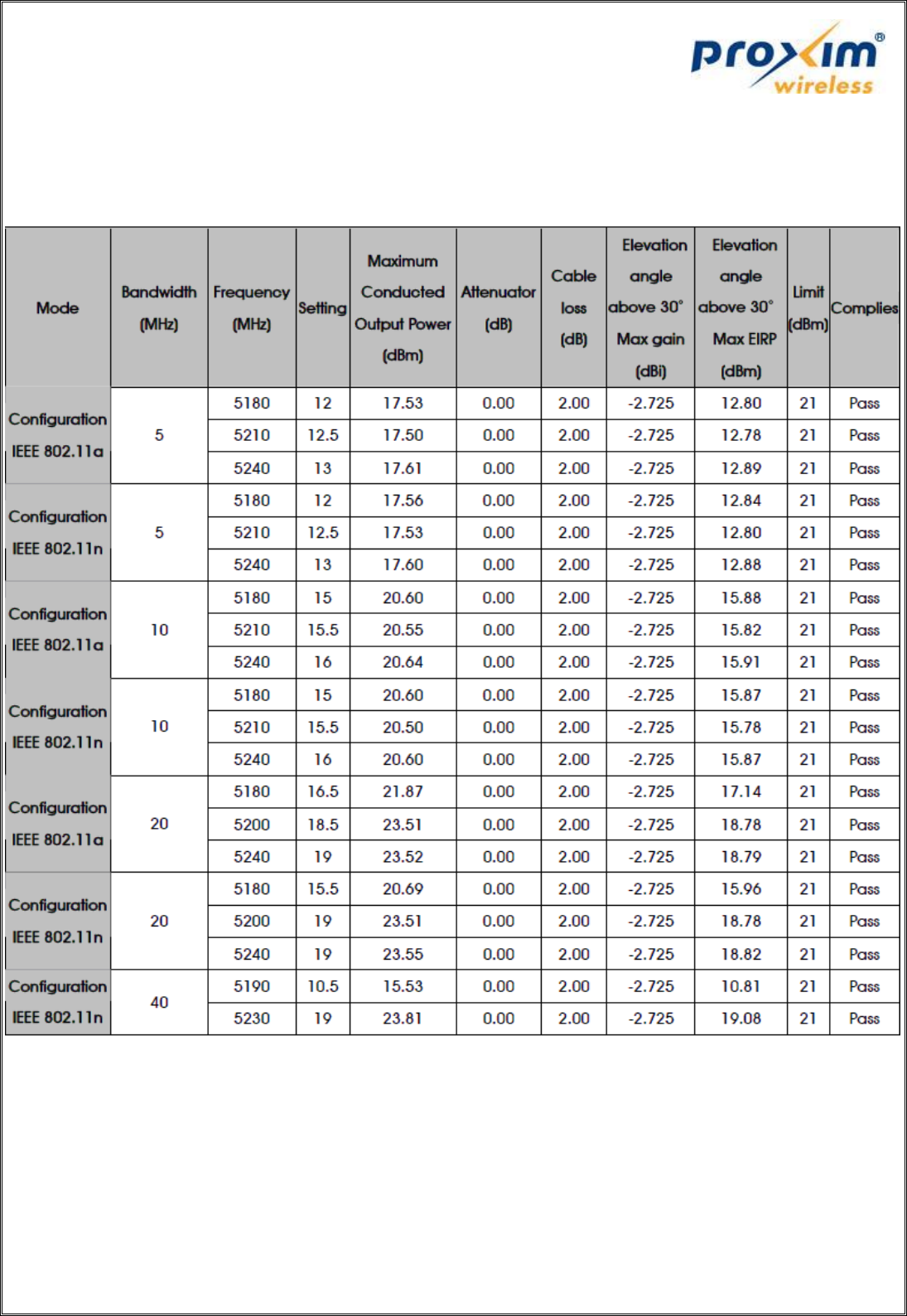
Table 3: Maximum EIRP values at an angle greater than 30 deg for the Antenna Model "MA-WB55-20”
with FCC ID “HZB-PROXMB82”
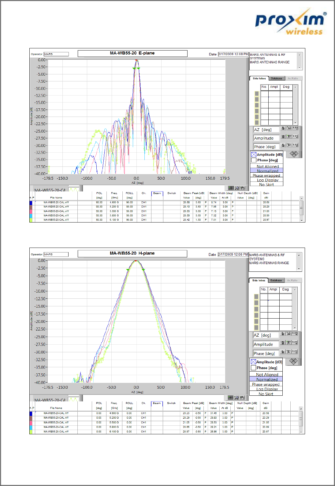
Figure 3: Radiation pattern for the Antenna Model "MA-WB55-30, E-plane"
Figure 4: Radiation pattern for the Antenna Model "MA-WB55-20, H-plane"
Antenna Model No: SAA08-220570
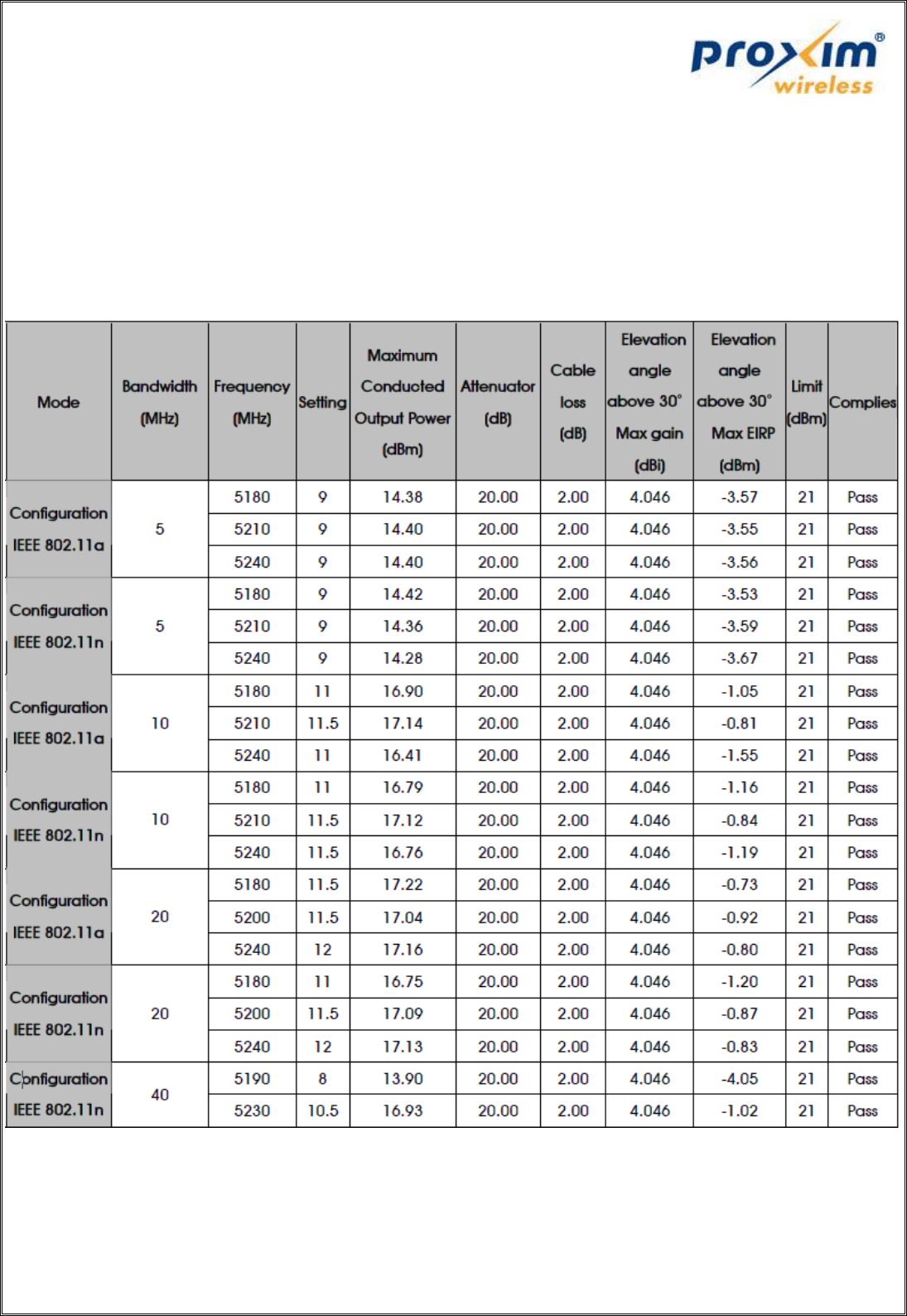
Gain: 10dBi
Antenna Type: Omni Antenna
Table 4: Maximum EIRP values at an angle greater than 30 deg for the Antenna Model "SAA08-220570”
with the FCC ID “HZB-PROXMB82”
2. FCC ID: HZB-XB92WFR
Antenna Model No: MA-WA55-30
Gain: 30dBi
Antenna Type: Panel Antenna, Linear Polarization (Vertical or Horizontal), 50 Bandwidth
Table 5: Maximum EIRP values at an angle greater than 30 deg for the Antenna Model "MA-WA55-30”
with the FCC ID “HZB-XB92WFR”
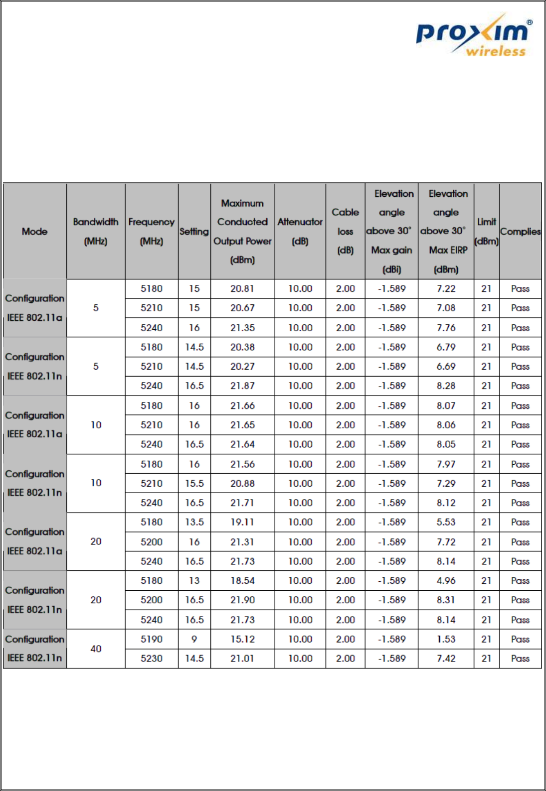
Antenna Model No: MA-WB55-20
Gain: 20dBi
Antenna Type: Sector Antenna, Linear Polarization (Vertical)
Table 6: Maximum EIRP values at an angle greater than 30 deg for the Antenna Model "MA-WB55-20”
with the FCC ID “HZB-XB92WFR”
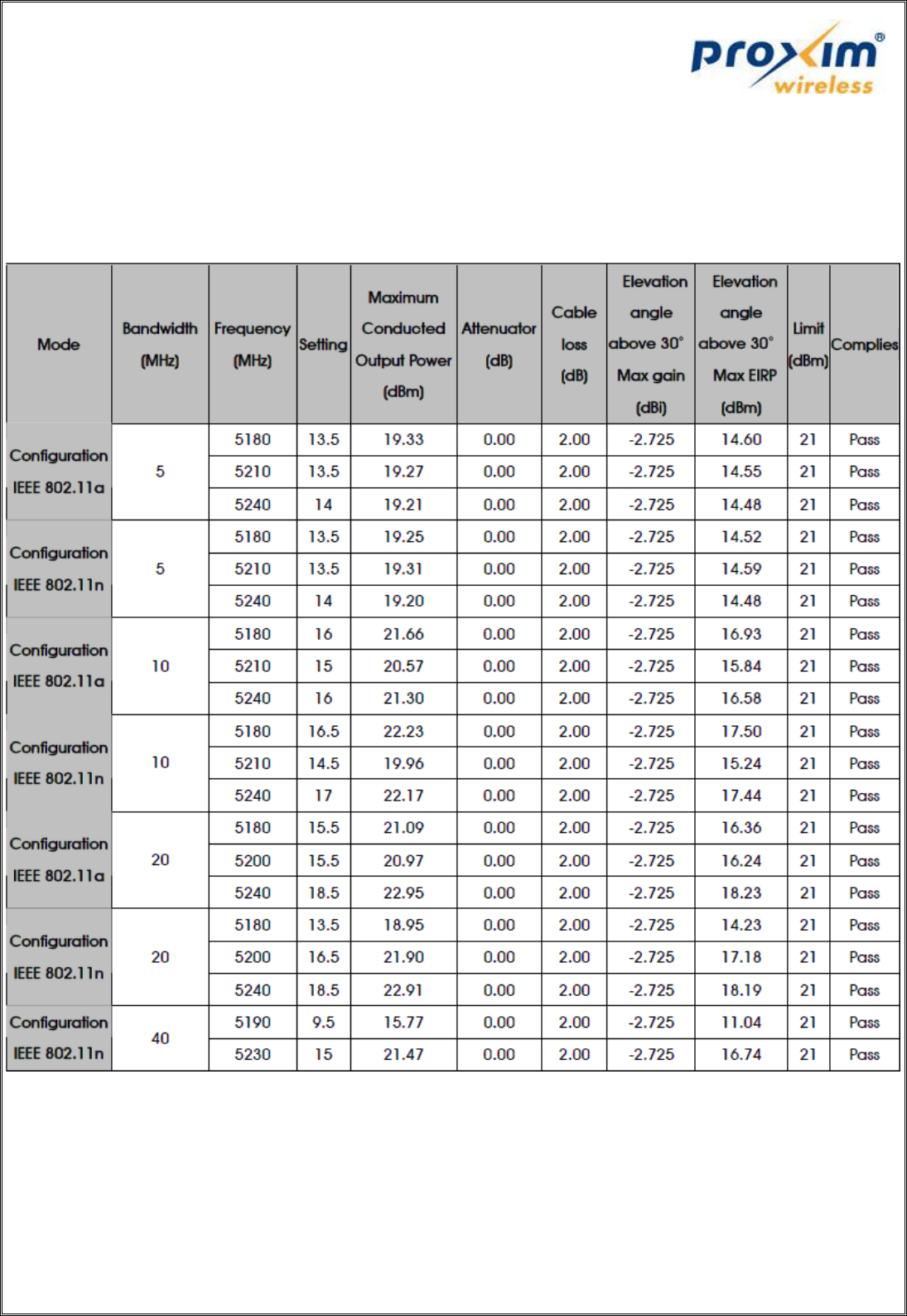
Antenna Model No: SAA08- 220570
Gain: 10dBi
Antenna Type: Omni Antenna
Table 7: Maximum EIRP values at an angle greater than 30 deg for the Antenna Model "SAA08-220570”
with the FCC ID “HZB-XB92WFR”
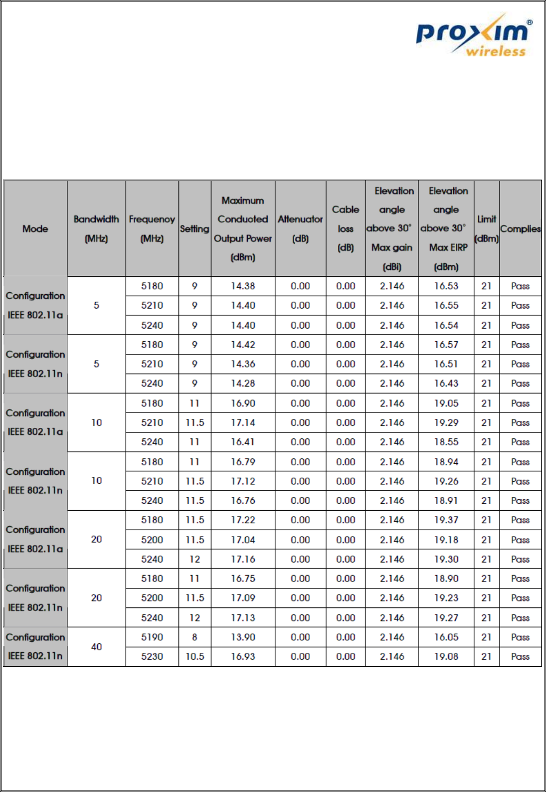
Antenna Model No: GTT-AC-05-001
Gain: 16dBi
Antenna Type: Panel Antenna
Table 8: Maximum EIRP values at an angle greater than 30 deg for the Antenna Model "GTT-AC-05-001”
with the FCC ID “HZB-XB92WFR”
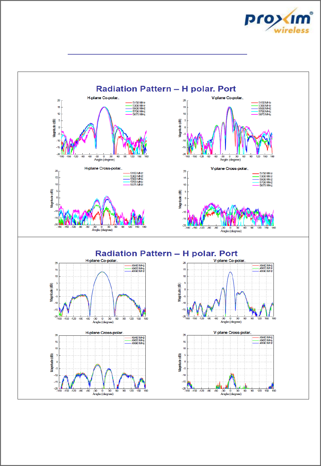
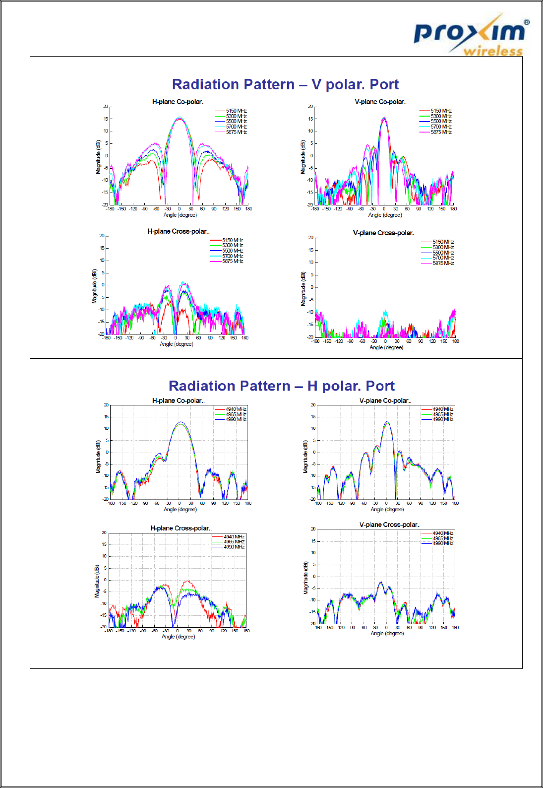
Radiation Patterns for GTT-AC-05-001 Model Antenna
3. FCC ID: HZB-XB92WLE
Antenna Model No: MA-WA55-30
Gain: 30dBi
Antenna Type: Panel Antenna, Linear Polarization (Vertical or Horizontal), 50 Bandwidth
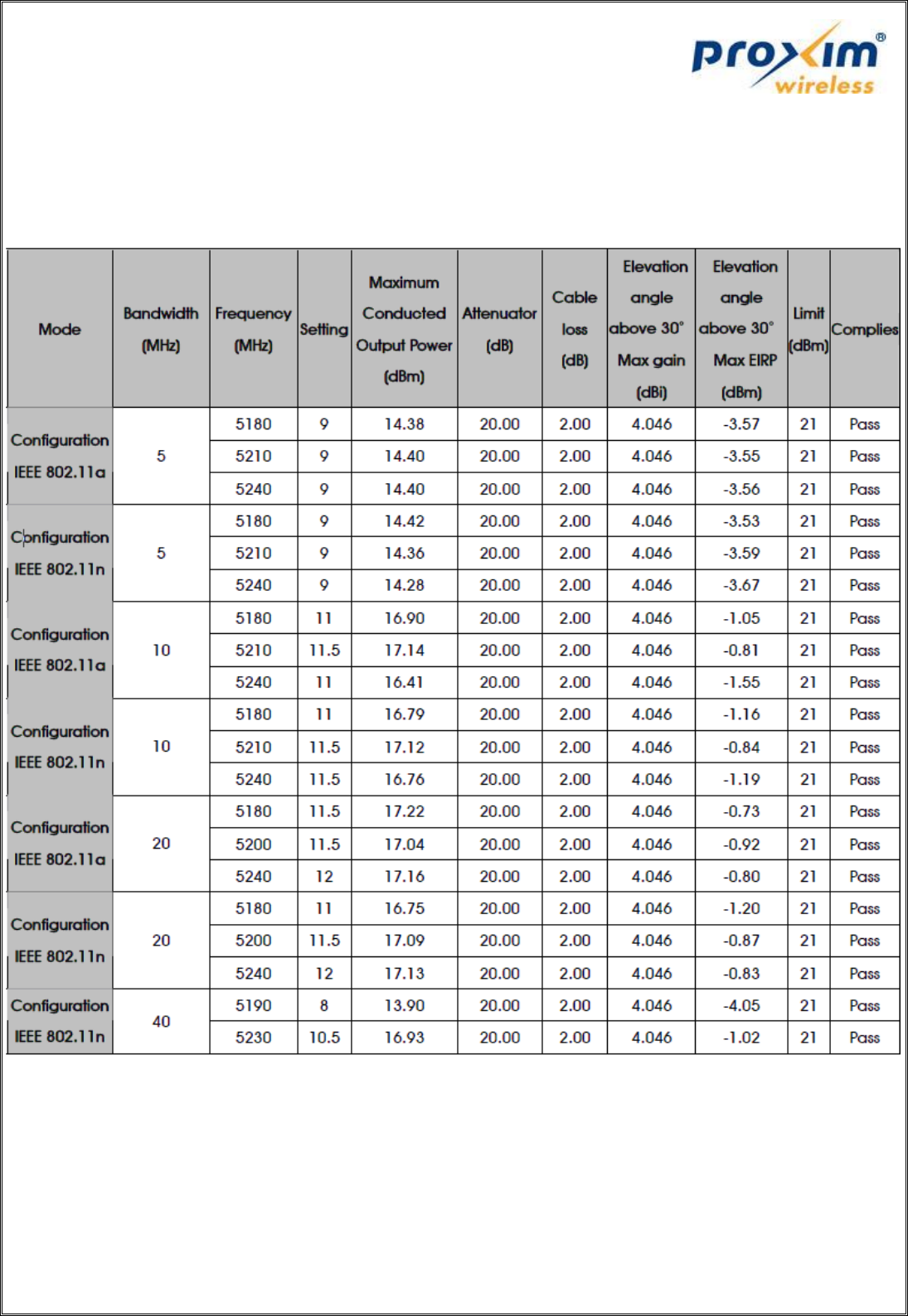
Table 9: Maximum EIRP values at an angle greater than 30 deg for the Antenna Model "MA-WA55-30”
with the FCC ID “HZB-XB92WLE”
Antenna Model No: MA-WB55-20
Gain: 20dBi
Antenna Type: Sector Antenna, Linear Polarization (Vertical)
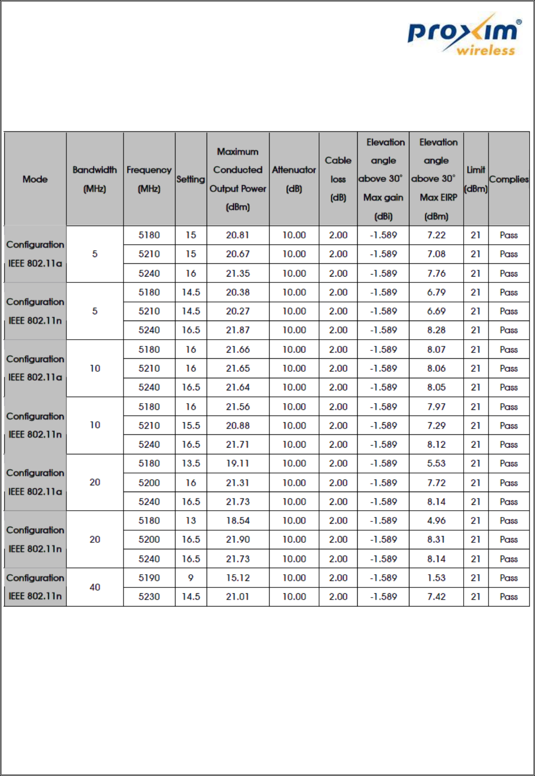
Table 10: Maximum EIRP values at an angle greater than 30 deg for the Antenna Model "MA-WB55-20”
with the FCC ID “HZB-XB92WLE”
Antenna Model No: SAA08-220570
Gain: 10dBi
Antenna Type: Omni Antenna
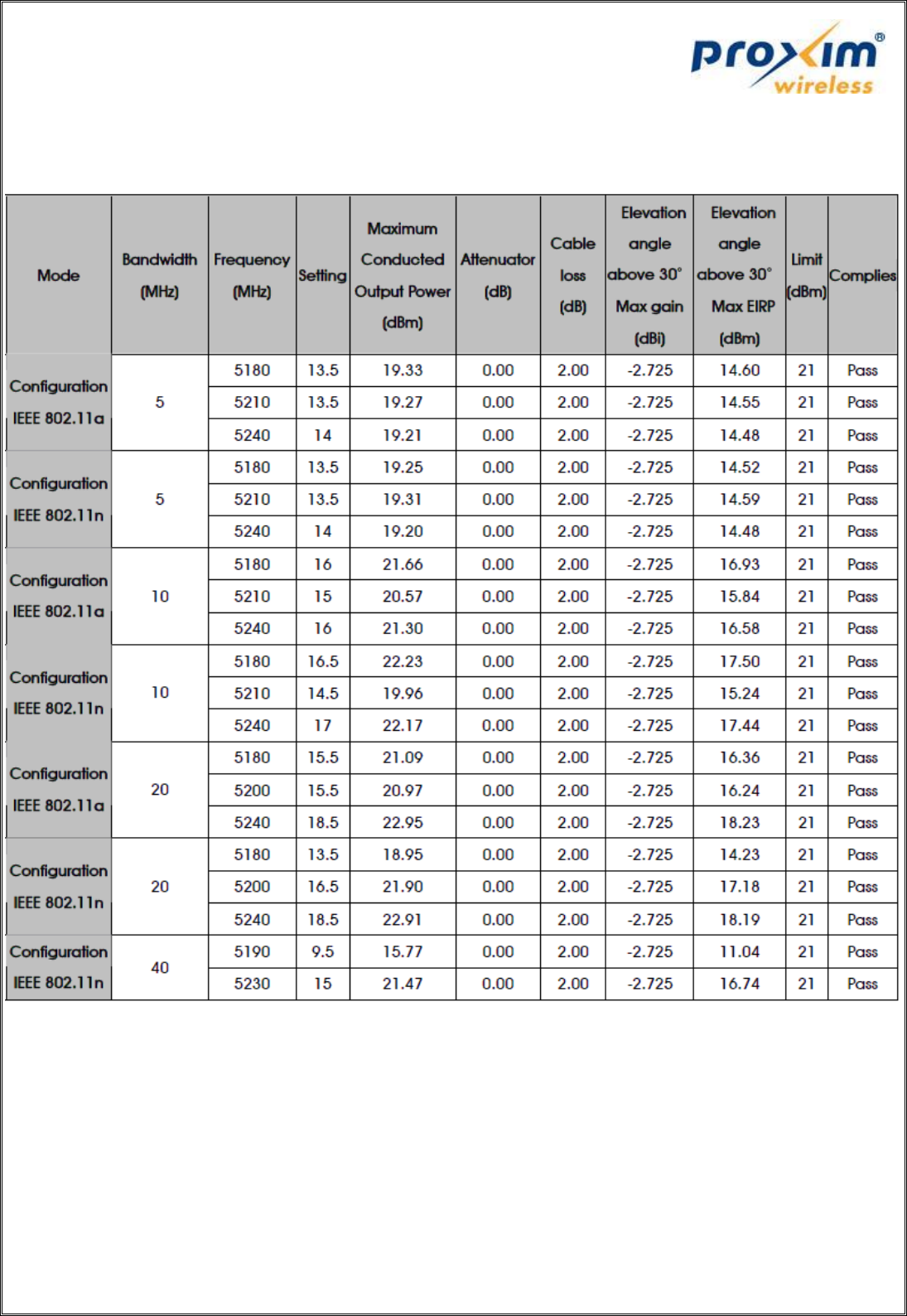
Table 11: Maximum EIRP values at an angle greater than 30 deg for the Antenna Model "SAA08-220570”
with the FCC ID “HZB-XB92WLE”
Antenna Model No: GTT-AC-05-001
Gain: 16dBi
Antenna Type: Panel Antenna
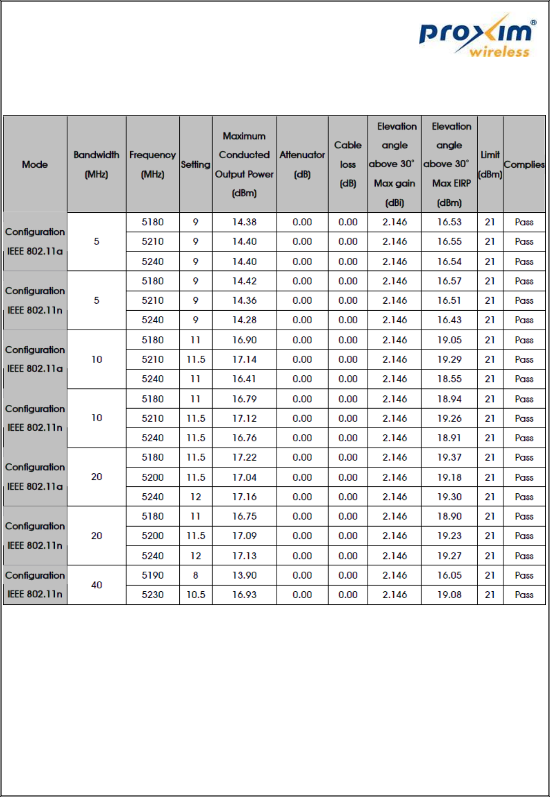
Table 12: Maximum EIRP values at an angle greater than 30 deg for the Antenna Model "GTT-AC-05-001”
with the FCC ID “HZB-XB92WLE”
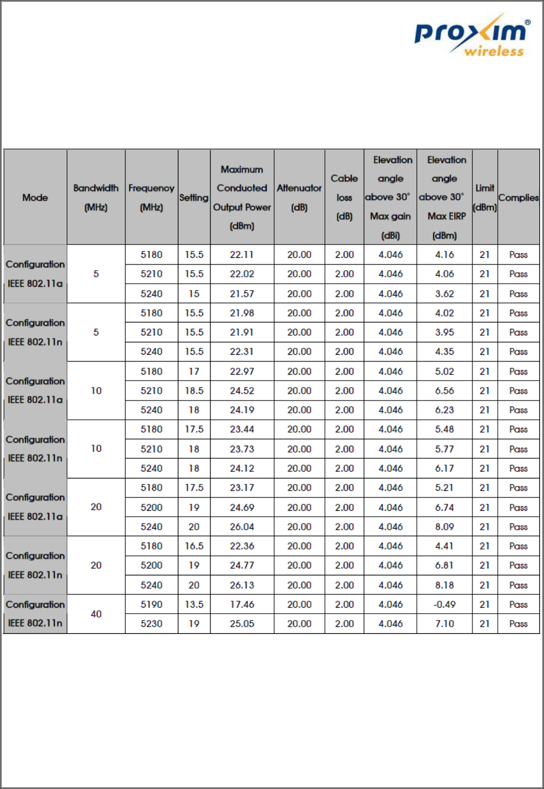
4. FCC ID: HZB-MB83HP5
Antenna Model No: MA-WA55-30
Gain: 30dBi
Antenna Type: Panel Antenna, Linear Polarization (Vertical or Horizontal), 50 Bandwidth
Table 13: Maximum EIRP values at an angle greater than 30 deg for the Antenna Model "MA-WA55-30”
with the FCC ID “HZB-MB83HP5”
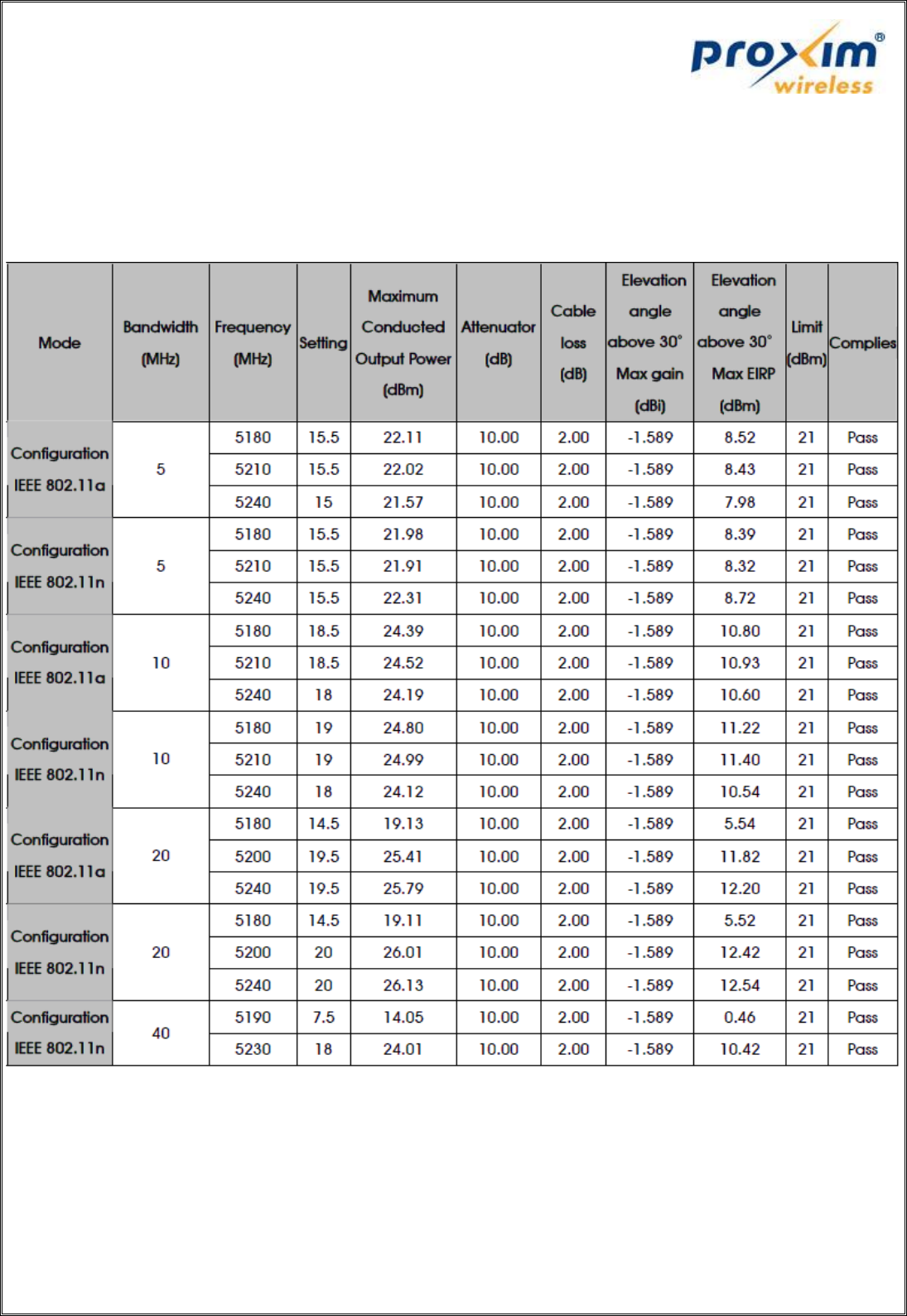
Antenna Model No: MA-WB55-20
Gain: 20dBi
Antenna Type: Sector Antenna, Linear Polarization (Vertical)
Table 14: Maximum EIRP values at an angle greater than 30 deg for the Antenna Model "MA-WB55-20”
with the FCC ID “HZB-MB83HP5”
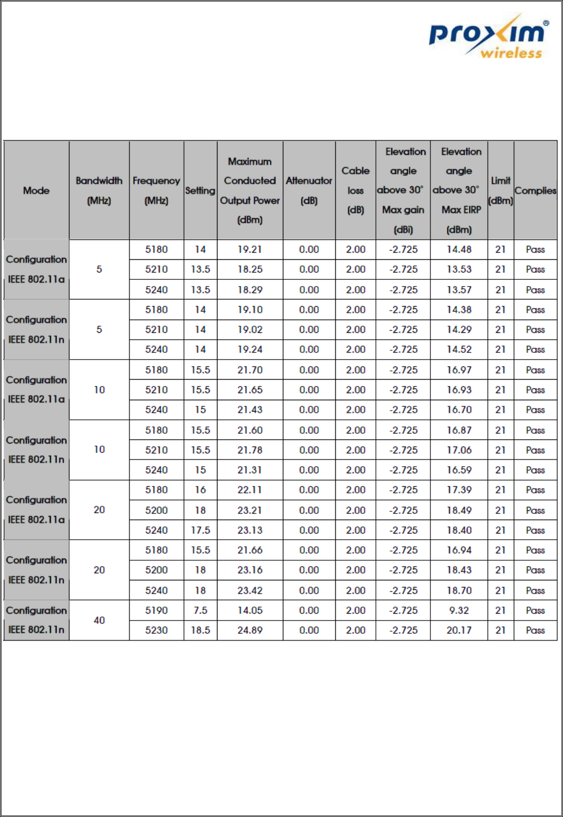
Antenna Model No: SAA08-220570
Gain: 10dBi
Antenna Type: Omni Antenna
Table 15: Maximum EIRP values at an angle greater than 30 deg for the Antenna Model "SAA08-220570”
with the FCC ID “HZB-MB83HP5”
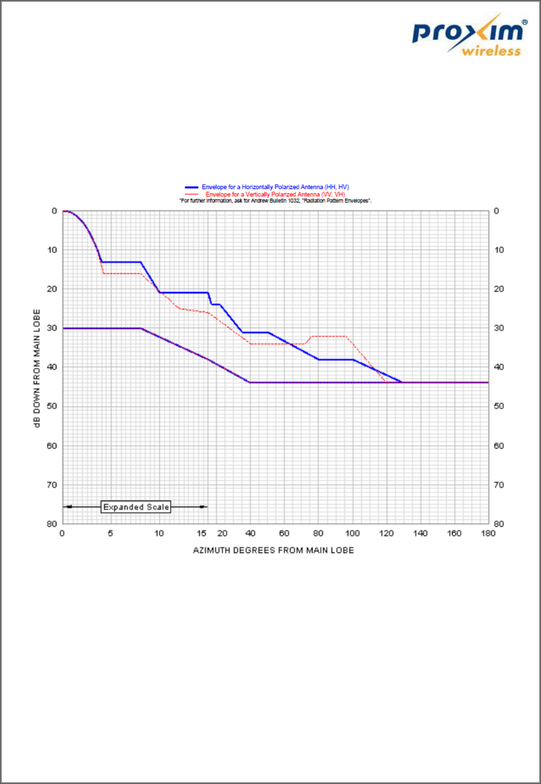
Antenna Model No: PX3F-52-N7A
Gain: 34dBi
Antenna Type: Dish Antenna
Figure 5: Radiation pattern for the Antenna Model "PX3F-52-N7A”
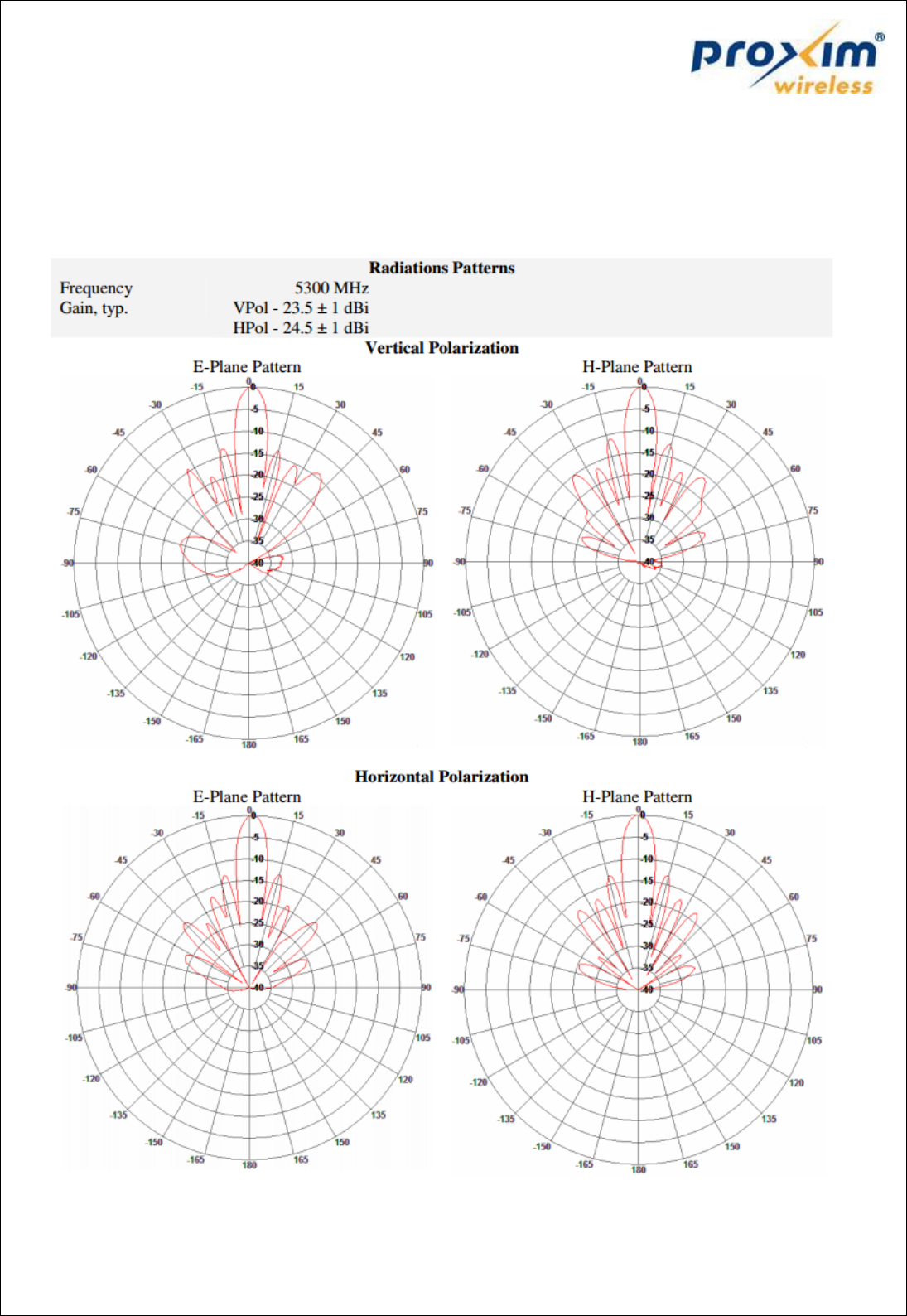
Antenna Model No: MA-WA56-DP25N
Gain: 23.5dBi
Antenna Type: Panel Antenna
Figure 6: Radiation patterns for the Antenna Model "MA-WA56-DP25N"
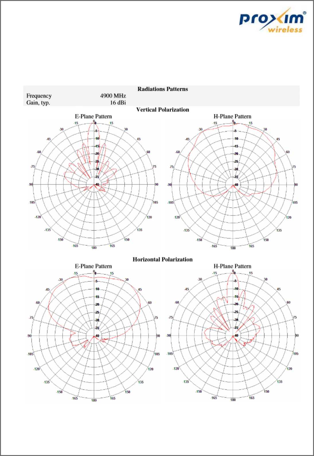
Antenna Model No: MA-WD56-DP16
Gain: 16dBi
Antenna Type: Sector Antenna
Figure 7: Radiation patterns for the Antenna Model "MA-WD56-DP16"