Proxim Wireless XB92WLE 802.11 a/n PCIe Module User Manual module manual ok
Proxim Wireless Corporation 802.11 a/n PCIe Module module manual ok
Contents
User Manual
Warning Statement
FCC NOTICE
This device has been tested and found to comply with the limits for a Class B
digital device, pursuant to Part 15 of the FCC Rules. These limits are designed to
provide reasonable protection against harmful interference in a residential
installation. This device generates uses and can radiate radio frequency energy
and, if not installed and used in accordance with the instructions, may cause
harmful interference to radio communications. However, there is no
guarantee that interference will not occur in a particular installation. If this device
does cause harmful interference to radio or television reception, the user is
encouraged to try to correct the interference by one or more of the following
measures:
• Reorient or relocate the receiving antenna.
• Connect the computer to an outlet on a circuit different from that to which the
receiver is connected.
• Increase the separation between the computer and receiver.
• Consult the dealer or an experienced radio/TV technician for help.
Caution: Any changes or modifications not expressly approved by the grantee of
this device could void the user's authority to operate the equipment.
FCC Compliance Statement: This device complies with Part 15 of the FCC
Rules. Operation is subject to the following two conditions:
This device may not cause harmful interference, and
This device must accept any interference received, including interference that
may cause undesired operation.
RF Exposure warning
The equipment complies with FCC RF exposure limits set forth for an uncontrolled
environment.
This device and its antenna(s) must not be co-located with any other transmitters
except in accordance with FCC multi-transmitter product procedures.
Refering to the multi-transmitter policy, multiple-transmitter(s) and module(s) can
be operated simultaneously without C2P.
For product available in the USA/Canada market, only channel 1~11 can be
operated. Selection of other channels is not possible.
This device is going to be operated in 5.15~5.25GHz frequency range, it is
restricted in indoor environment only.
Devices will not permit operations on channels 120-132 for 11a and 11n/a which
overlap the 5600 - 5650 MHz band.
IMPORTANT NOTE:
This module is intended for OEM integrator. The OEM integrator is responsible for
the compliance to all the rules that apply to the product into which this certified RF
module is integrated.
Additional testing and certification may be necessary when multiple modules are
used.
20cm minimum distance has to be able to be maintained between the antenna
and the users for the host this module is integrated into. Under such configuration,
the FCC radiation exposure limits set forth for an population/uncontrolled
environment can be satisfied.
USERS MANUAL OF THE END PRODUCT:
In the users manual of the end product, the end user has to be informed to keep at
least 20cm separation with the antenna while this end product is installed and
operated. The end user has to be informed that the FCC radio-frequency
exposure guidelines for an uncontrolled environment can be satisfied. The end
user has to also be informed that any changes or modifications not expressly
approved by the manufacturer could void the user's authority to operate this
equipment. If the size of the end product is smaller than 8x10cm, then additional
FCC part 15.19 statement is required to be available in the users manual: This
device complies with Part 15 of FCC rules. Operation is subject to the following
two conditions: (1) this device may not cause harmful interference and (2) this
device must accept any interference received, including interference that may
cause undesired operation.
LABEL OF THE END PRODUCT:
The final end product must be labeled in a visible area with the following "
Contains TX FCC ID: HZB-XB92WLE ". If the size of the end product is larger
than 8x10cm, then the following FCC part 15.19 statement has to also be
available on the label: This device complies with Part 15 of FCC rules. Operation
is subject to the following two conditions: (1) this device may not cause harmful
interference and (2) this device must accept any interference received, including
interference that may cause undesired operation.
IC NOTICE
This device complies with Industry Canada license-exempt RSS standard(s).
Operation is subject to the following two conditions: (1) this device may not cause
interference, and (2) this device must accept any interference, including
interference that may cause undesired operation of the device.
Le présent appareil est conforme aux CNR d'Industrie Canada applicables aux appareils radio
exempts de licence. L'exploitation est autorisée aux deux conditions suivantes : (1) l'appareil ne
doit pas produire de brouillage, et (2) l'utilisateur de l'appareil doit accepter tout brouillage
radioélectrique subi, même si le brouillage est susceptible d'en compromettre le fonctionnement.
For product available in the USA/Canada market, only channel 1~11 can be
operated. Selection of other channels is not possible.
Pour les produits disponibles aux États-Unis / Canada du marché, seul le canal 1 à 11 peuvent
être exploités. Sélection d'autres canaux n'est pas possible.
This device and its antenna(s) must not be co-located with any other transmitters except
in accordance with IC multi-transmitter product procedures.
Refering to the multi-transmitter policy, multiple-transmitter(s) and module(s) can be
operated simultaneously without reassessment permissive change.
Cet appareil et son antenne (s) ne doit pas être co-localisés ou fonctionnement en association
avec une autre antenne ou transmetteur.
The device could automatically discontinue transmission in case of absence of
information to transmit, or operational failure. Note that this is not intended to
prohibit transmission of control or signaling information or the use of repetitive
codes where required by the technology.
Le dispositif pourrait automatiquement cesser d'émettre en cas d'absence d'informations à
transmettre, ou une défaillance opérationnelle. Notez que ce n'est pas l'intention d'interdire la
transmission des informations de contrôle ou de signalisation ou l'utilisation de codes répétitifs
lorsque requis par la technologie.
Dynamic Frequency Selection (DFS) for devices operating in the bands 5250-
5350 MHz,
5470-5600 MHz and 5650-5725 MHz
Sélection dynamique de fréquences (DFS) pour les dispositifs fonctionnant dans les bandes
5250-5350 MHz, 5470-5600 MHz et 5650-5725 MHz
The device for the band 5150-5250 MHz is only for indoor usage to reduce
potential for harmful interference to co-channel mobile satellite systems.
les dispositifs fonctionnant dans la bande 5150-5250 MHz sont réservés uniquement pour une
utilisation à l’intérieur afin de réduire les risques de brouillage préjudiciable aux systèmes de
satellites mobiles utilisant les mêmes canaux.
The maximum antenna gain permitted (for devices in the bands 5250-5350 MHz
and 5470-5725 MHz) to comply with the e.i.r.p. limit.
le gain maximal d’antenne permis pour les dispositifs utilisant les bandes 5250-5350 MHz et
5470-5725 MHz doit se conformer à la limite de p.i.r.e.;
Users should also be advised that high-power radars are allocated as primary
users (i.e. priority
users) of the bands 5250-5350 MHz and 5650-5850 MHz and that these radars
could cause interference and/or damage to LE-LAN devices.
De plus, les utilisateurs devraient aussi être avisés que les utilisateurs de radars de haute
puissance sont désignés utilisateurs principaux (c.-à-d., qu’ils ont la priorité) pour les bandes
5250-5350 MHz et 5650-5850 MHz et que ces radars pourraient causer du brouillage et/ou des
dommages aux dispositifs LAN-EL.
IMPORTANT NOTE:
IC Radiation Exposure Statement:
This equipment complies with IC RSS-102 radiation exposure limits set forth for
an uncontrolled environment. This equipment should be installed and operated
with minimum distance 20cm between the radiator & your body.
Cet équipement est conforme aux limites d'exposition aux rayonnements IC établies pour un
environnement non contrôlé. Cet équipement doit être installé et utilisé avec un minimum de 20
cm de distance entre la source de rayonnement et votre corps.
IMPORTANT NOTE:
This module is intended for OEM integrator. The OEM integrator is still
responsible for the IC compliance requirement of the end product, which
integrates this module.
USERS MANUAL OF THE END PRODUCT:
In the users manual of the end product, the end user has to be informed to keep at
least 20cm separation with the antenna while this end product is installed and
operated. The end user has to be informed that the IC radio-frequency exposure
guidelines for an uncontrolled environment can be satisfied. The end user has to
also be informed that any changes or modifications not expressly approved by the
manufacturer could void the user's authority to operate this equipment. IC
statement is required to be available in the users manual: This Class B digital
apparatus complies with Canadian ICES-003. Operation is subject to the following
two conditions: (1) this device may not cause harmful interference and (2) this
device must accept any interference received, including interference that may
cause undesired operation.
LABEL OF THE END PRODUCT:
The final end product must be labeled in a visible area with the following "
Contains TX IC : 1856A-XB92WLE ".
This device complies with the Electromagnetic Compatibility Directive
(89/336/EEC) issued by the Commission of the European Community.
Compliance with this directive implies conformity to the following European Norms
(in brackets are the equivalent international standards.)
Electromagnetic Interference (Conduction and Radiation): EN 55022 (CISPR
22)
Electromagnetic Immunity: EN 55024 (IEC61000-4-2, 3, 4, 5, 6, 8, 11)
Low Voltage Directive: EN 60 950: 1992+A1: 1993+A2: 1993+A3: 1995+A4:
1996+A11: 1997.
CE Mark: following the provisions of the EC directive.
The wireless card in this product complies with the R&TTE Directive (1999/5/EC)
issued by the Commission of the European Community. Compliance with this
directive implies conformity to
the following:
EMC Standards: FCC: 47 CFR Part 15, Subpart B, 47 CFR Part 15, Subpart C
(Section 15.247); CE:
EN 300 328-2, EN 300 826 (EN 301 489-17)
CE Mark: following the provisions of the EC directive.
Manual Version: 2.08c (June 2010)
This manual is written based on Firmware version 2.00
Overview the Product
Introduction
The high-performance Wireless Network Access Point (AP) is designed for
enterprise and public access applications. Embedded with the Atheros chipset, it
boasts network robustness, stability and wider network coverage. Based on
802.11n (Draft 2.0), the access point supports high-speed data transmission of up
to 300Mbps.
The access point is capable of operating in different modes, which makes it
suitable for a wide variety of wirelessapplications, including long-distance
deployments.
Designed with dual polarization high gain antenna it offers a compact, rugged
design for outdoor installation and excellent performance.
Moreover, its integrated Power over Ethernet (PoE) allows the access point to be
used in areas where power outlets are not readily available.
To protect your security and privacy, the access point is armed with many
enhanced and latest wireless security features such as IEEE 802.11i standards,
MAC Address Filtering, IEEE 802.1x Authentication and 64/128-bit WEP (Wired
Equivalent Privacy) to ensure privacy for the heterogeneous mix of users within
the same wireless network.
The access point also incorporates a unique set of advanced features such as:
Virtual AP to deliver multiple services; Long-Range parameter fine-tuning which
provide the access point with the ability to auto-calculate parameters such as slot
time, ACK time-out and CTS time-out to achieve a longer range.
Features and Benefits
Point-to-Point & Point-to-MultiPoint Support
Point-to-Point and Point-to-MultiPoint communication between different buildings
enables you to bridge wireless clients that are kilometres apart while unifying the
networks.
Virtual AP (Multiple SSID)
Virtual AP implements mSSID (Multi-SSID) This allows a single wireless card to
be set up with multiple virtual AP connections with different SSIDs or BSSID
(Basic Service Set Identifier) and security modes.
Highly Secured Wireless Network
The access point supports the highest available wireless securitystandard:
IEEE802.11i compliant.
The access point also supports IEEE 802.1x for secure and centralized
user-based authentication.
Wireless clients are thus required to authenticate through highly secure methods
like EAP-TTLS and EAP-PEAP, in order to obtain access to the network.
uConfig Utility
The exclusive uConfig utility allows users to access the user-friendly Web
configuration interface of the access point without having to change the TCP/IP
setup of the workstation.
HTTPS
The access point supports HTTPS (SSL) in addition to the standard HTTP.
HTTPS (SSL) features additional authentication and encryption for secure
communication.
Telnet
Telnet allows a computer to remotely connect to the access point CLI
(Command Line Interface) for control and monitoring.
SSH SSH (Secure Shell Host) establishes a secure host connection to the access
point CLI for control and monitoring.
Operation Modes and Connection Examples
Access Point and Access Point WDS Mode
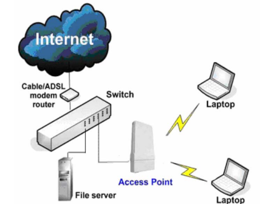
The Access Point Mode is the default mode of the device. It enables the
bridging of wireless clients to wired network infrastructure and enables
transparent access and communication with each other.
The illustration below shows a typical resources sharing application example
using this device. The wireless users are able to access the file server
connected to the switch, through the access point in Access Point Mode.
Access Point WDS Mode
This is mode is generally use for point-to-point or point-to-multi-point connection.
It is mainly use with Station WDS to build the point and multi-point connections.
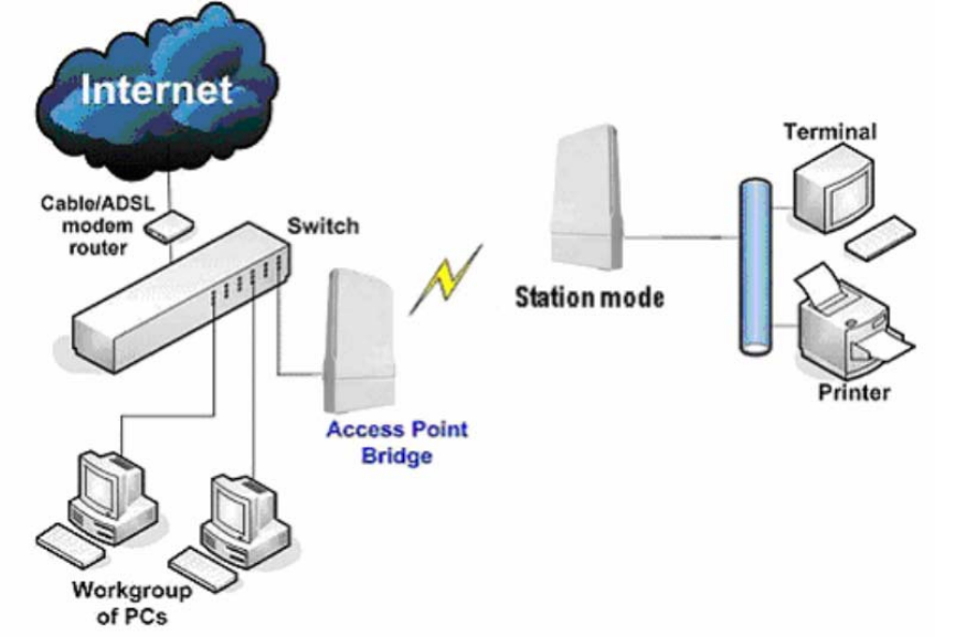
Station Mode
In Station mode the device acts as a wireless client.
When connected to an access point, it creates a network link between the
Ethernet network connected at this client device, and the wireless Ethernet
network connected at the access point.
In this example the workgroup PCs on the ethernet network connected to the
Station device can access the printer across the wireless connection to the
access point where the printer is connected.
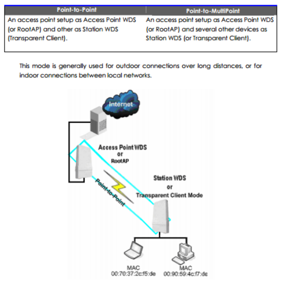
Station WDS Mode
Station WDS mode is similar to Station mode. The difference is Station WDS
must connect to access point configured to Access Point WDS (or RootAP)
mode.
Station WDS is mainly use for point-to–point connection between 2 buildings or
locations as far as several kilometer away.
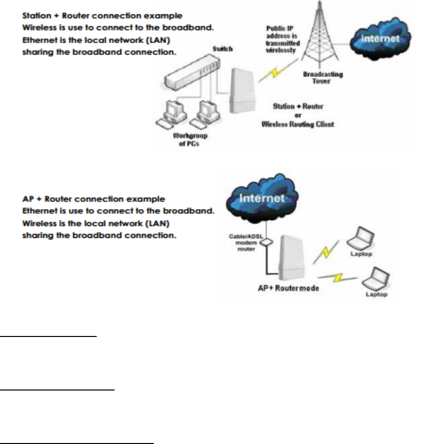
Router Mode
In Router Mode, the device also operates as a router.
Either the wireless or Ethernet can be setup as WAN connection to a broadband
modem. Wireless as WAN is known as Station + Router mode (or Wireless
Routing Client
mode) and Ethernet as WAN is known as AP + Router mode(or Gateway mode).
Device supports several types of broadband connections Static IP, Dynamic IP
and PPPoE. For setup details refer to the respective section.
The illustration below shows the Ethernet port is setup as the WAN port and the
wireless connection as the LAN.
Broadband Internet Access Type:
Static IP Address
Use Static IP Address you have subscribed a fixed IP or range IP addresses from
your ISP.
Dynamic IP Address
With Dynamic IP Address the device automatically request IP address from
modem or ISP.
PPP over Ethernet (PPPoE)
When using ADSL services provided byyour ISP support PPPoE connection.
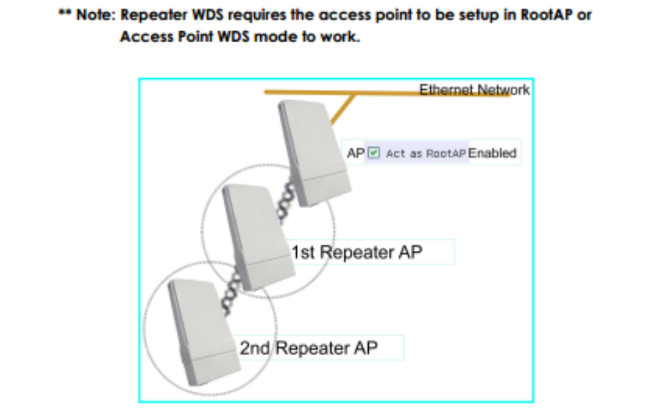
Repeater WDS Mode
Repeater WDS Mode to mainly to extend the wireless range and coverage of the
wireless network allowing access and communications over places generally
difficult for wireless clients to connect to the network.
In Repeater mode, the access point acts as a relay for network signals on the
network by regenerating the signals it receives, and retransmitting them to main
network infrastructure.
Detailed information on the Repeater mode is available in the Repeater Setup
section.
Install the Hardware
This section will show you how to install the hardware of the access point.
• Antenna Alignment
The antenna alignment of the access point must first be considered to ensure that
the signal is strong.
• Installation Direction
After considering the antenna alignment, the direction in which the access
point is facing must be considered to ensure that the signal is actually being
directed to the receiving end.
• Setting Up
Lastly, after making these considerations and confirming the final position
and facing direction of the access point, follow the instructions to physically set up
and complete the installation of the access point
Setup Requirements
• CAT5/5e Networking Cable.
• At least 1 computer installed with a web browser and a wired or wireless
network interface adapter.
• All network nodes installed with TCP/IP and properly configured IP address
parameters.
Mount the Unit on a Pole
Access point is designed to mount to a pole. The mounting method will be
described as shown below.
Note the following guidelines for choosing the best location for your wireless AP:
• Place the AP as close as possible tothe area where users will require
access to the WLAN.
• Choose an elevated location where trees, buildings and large steel
structures will not obstruct the antenna signals and which offers maximum
line-of-sight propagation with the users.
• Select an appropriate antenna to improve range and/or coverage and
the access point also lets you fine-tune parameters such as the transmit
power to achieve the best results