Psion 7527CBTRA2041M Workabout Pro G2 User Manual 7535 G2 Hand Held Computer
Psion Inc Workabout Pro G2 7535 G2 Hand Held Computer
Psion >
Contents
- 1. Users manual 7527C
- 2. Revised users manual part 1
- 3. Revised users manual part 2
- 4. Revised user manual part 3
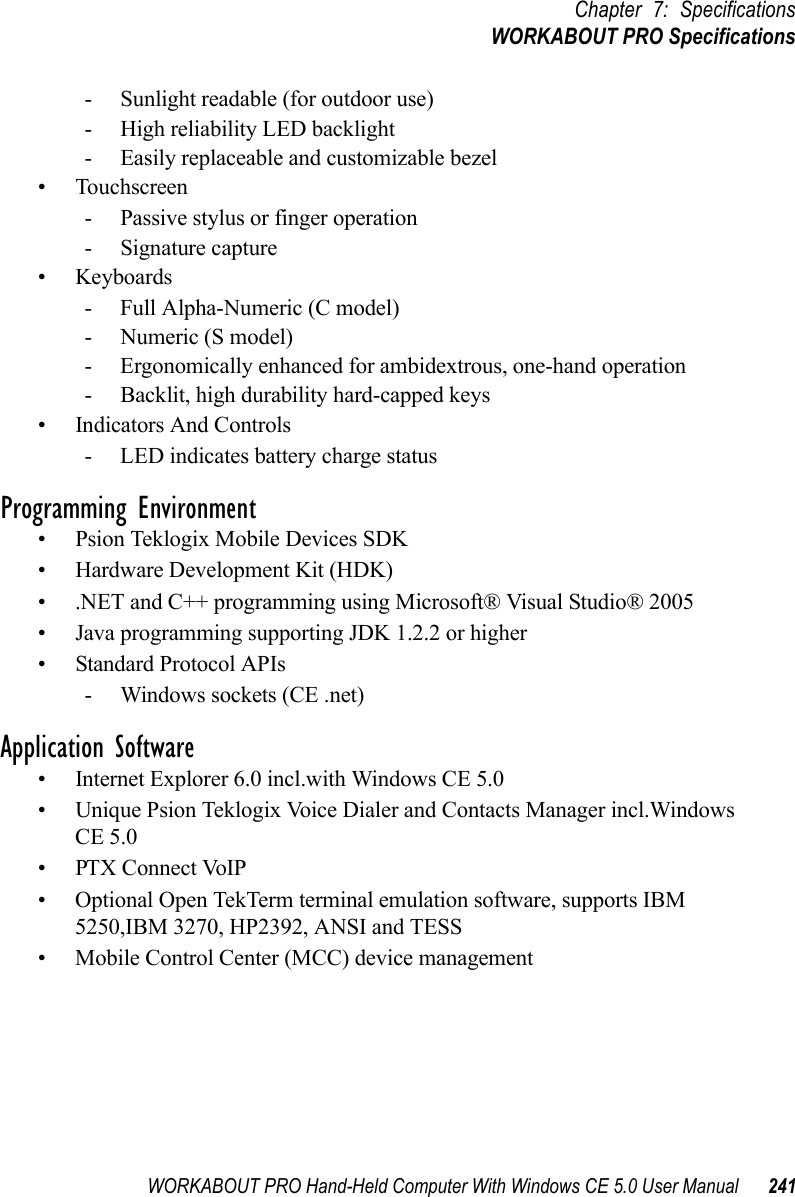
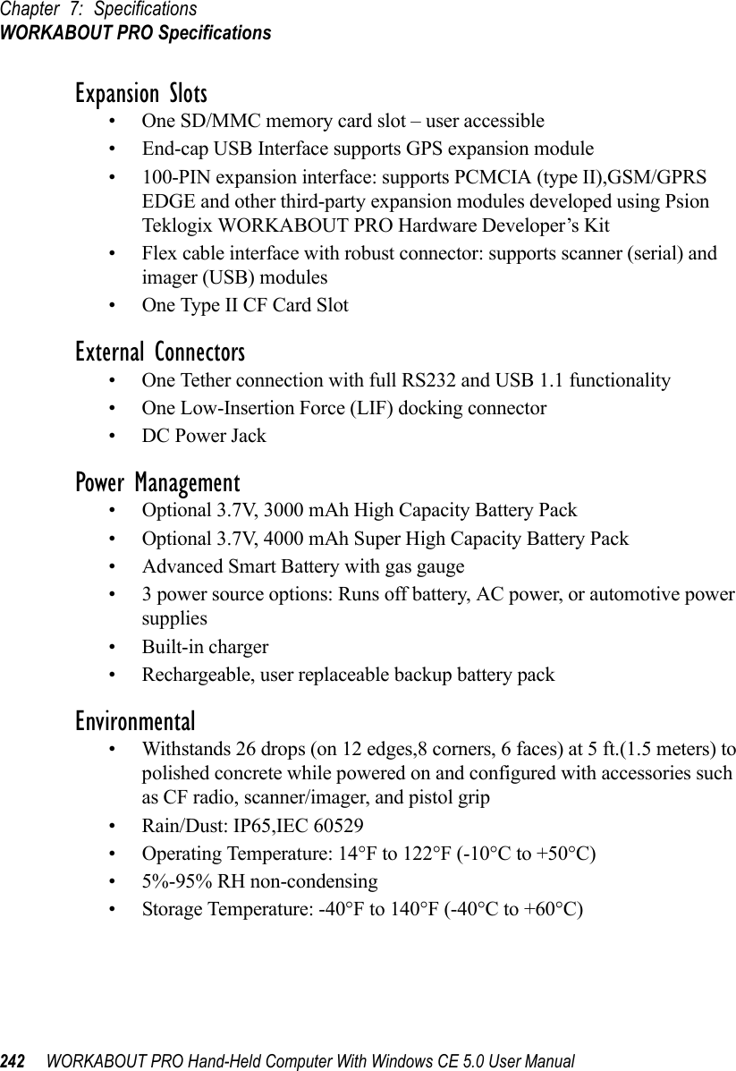
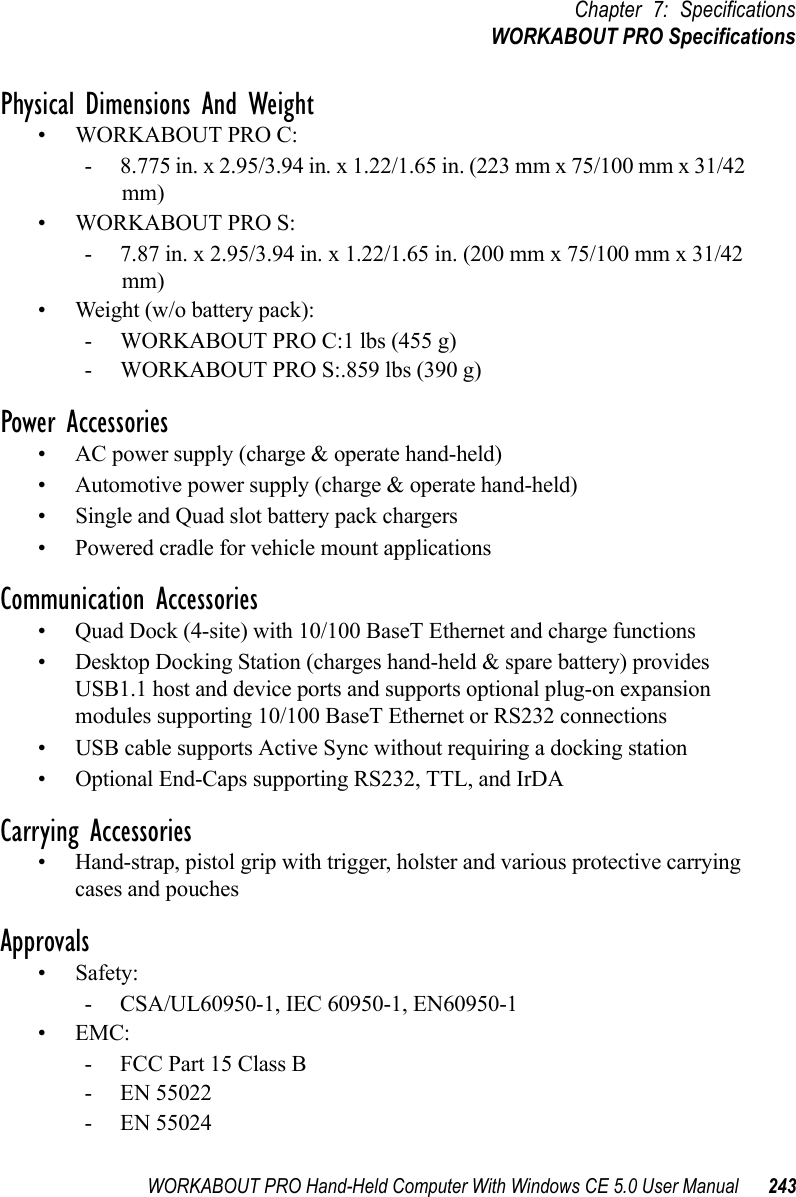
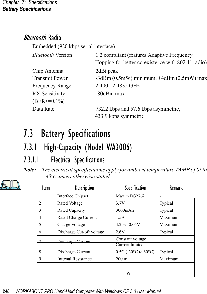
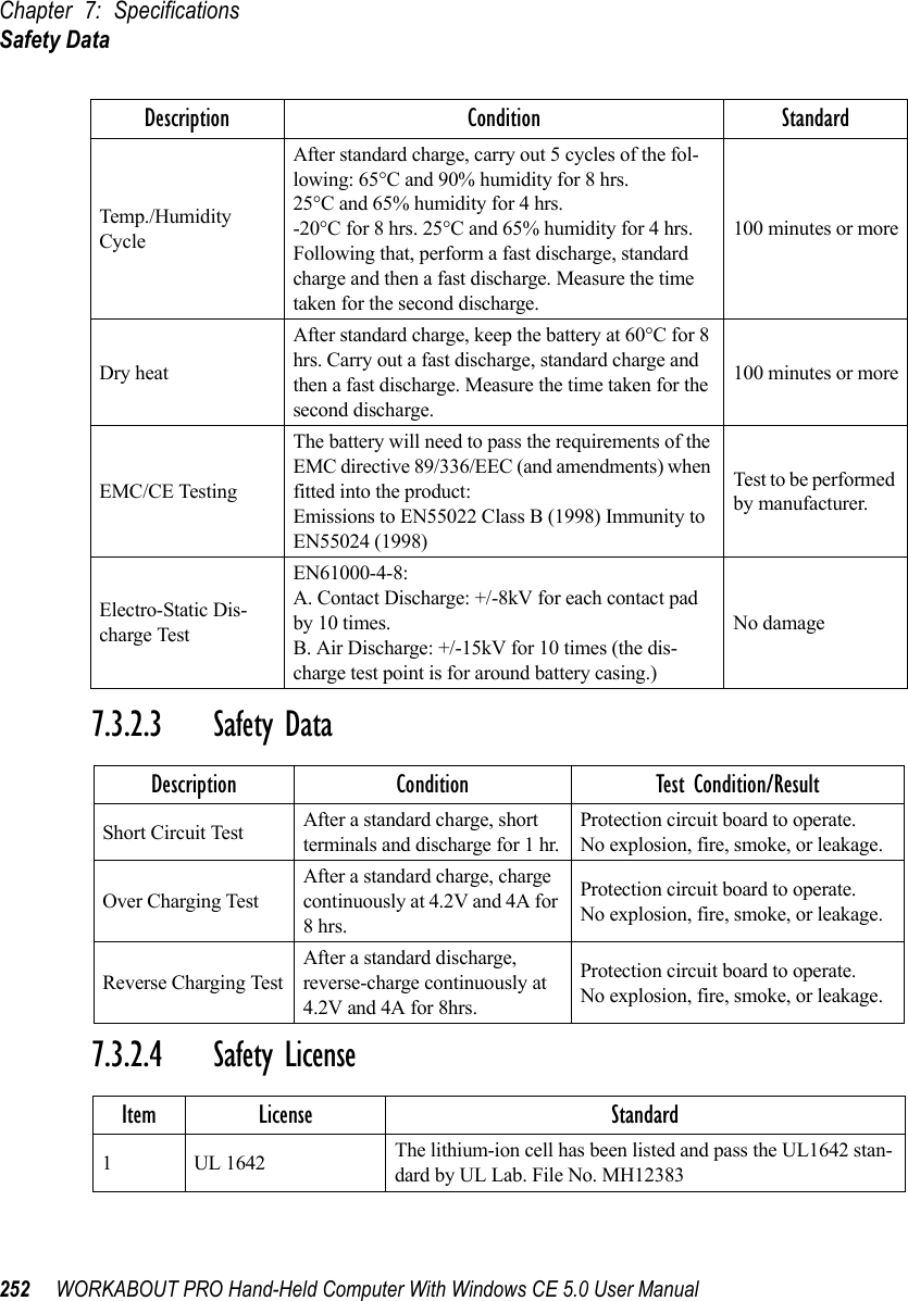
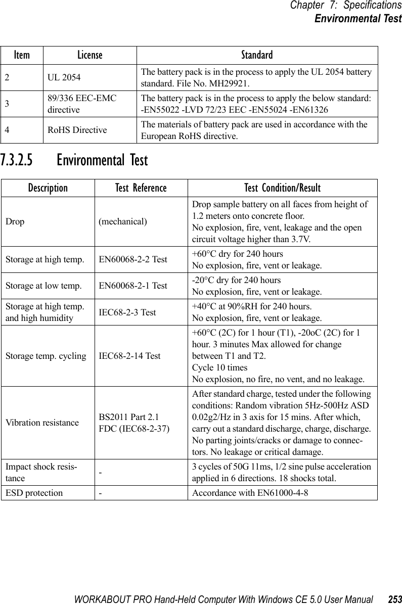
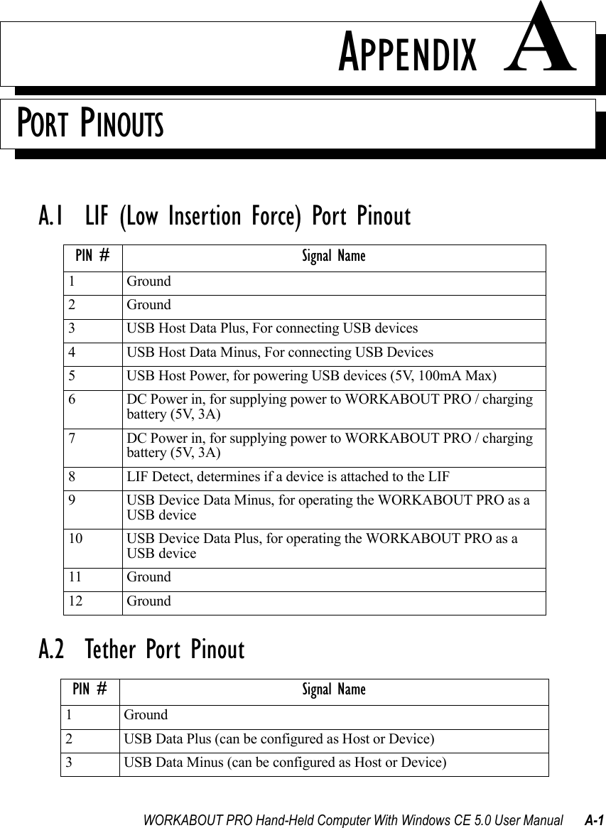
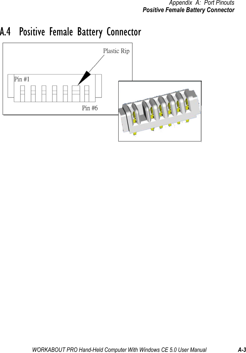
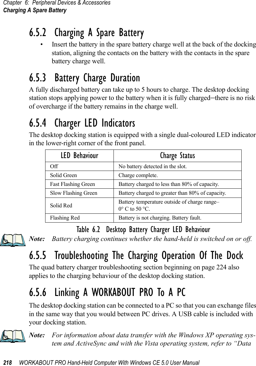
Revised user manual part 3
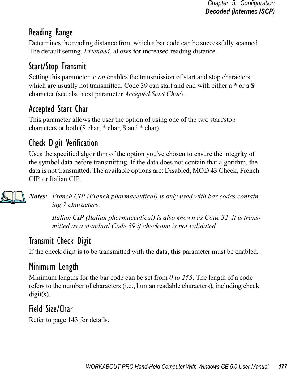
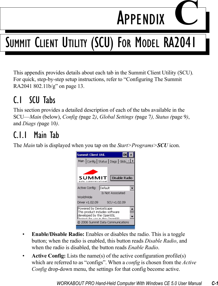
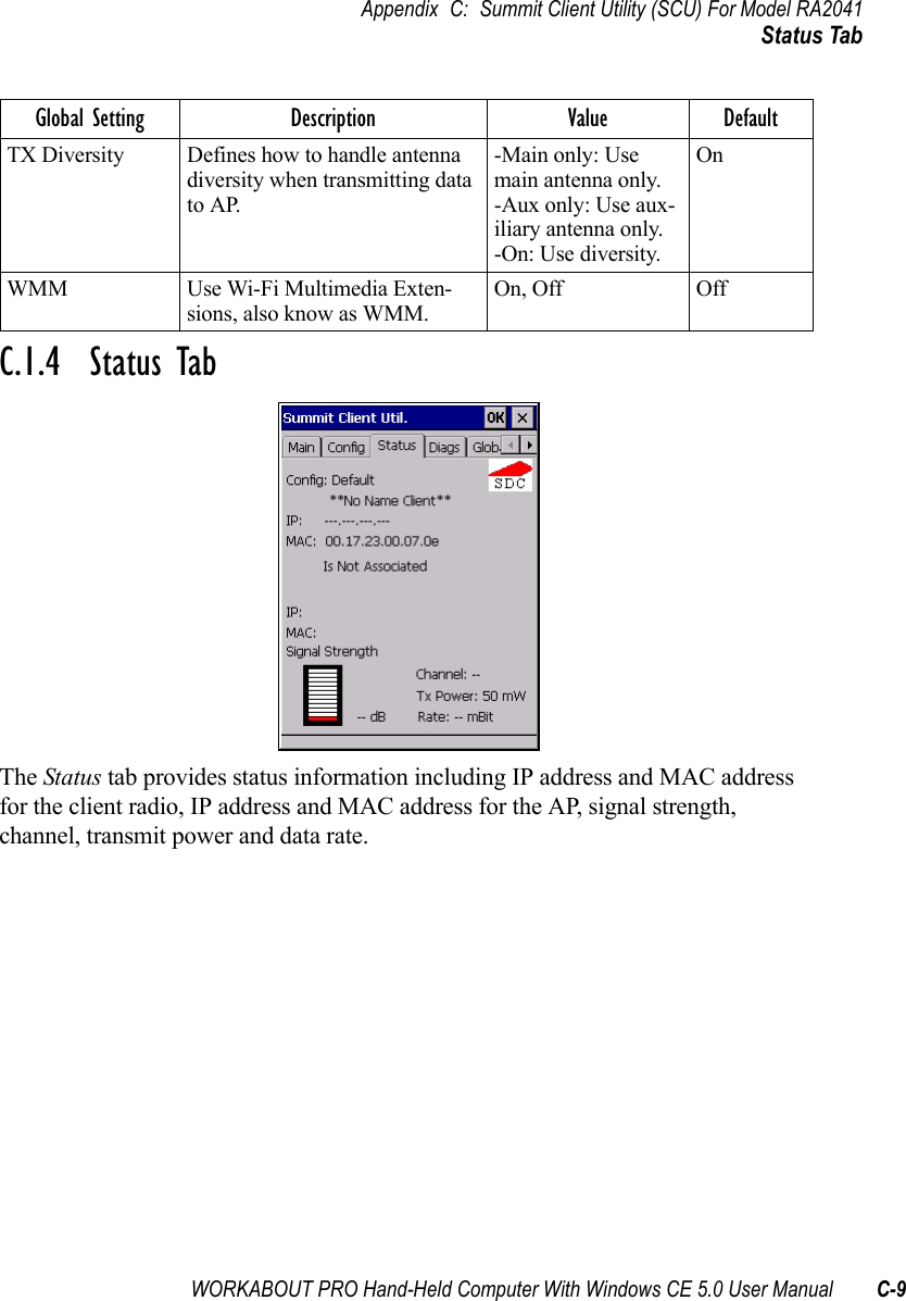
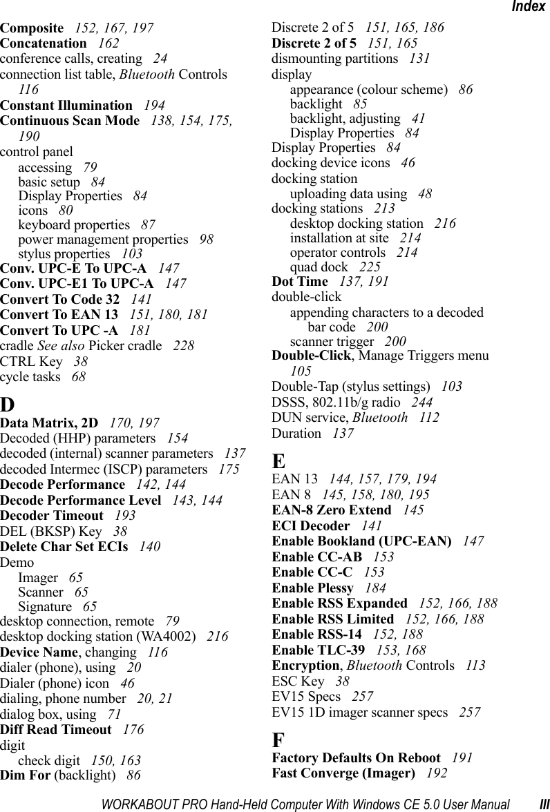
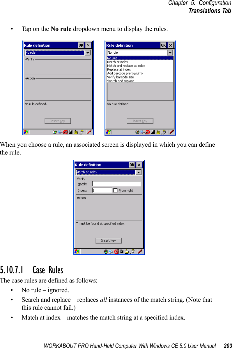
![Chapter 5: ConfigurationDecoded (Intermec ISCP)178 WORKABOUT PRO Hand-Held Computer With Windows CE 5.0 User Manual5.10.4.4 Code 128EnableSetting this parameter to on enables “Code 128”.GS1-128“GS1-128” is the GS1 implementation of the Code 128 barcode specification. The former correct name was UCC/EAN-128.GS1-128 Identifier“GS1-128 Identifier” allows the AIM ID " ]C1" for EAN 128 to be transmitted or removed. By default, this identifier is transmitted if EAN 128 is enabled.GTIN CompliantGTIN (global trade item number) processing transmits EAN 128 as the 14-character EAN/UCC GTIN. To use GTIN processing, you must activate the EAN 128 symbology.Important: When EAN 128 and GTIN processing are both activated, it is not possible to read normal EAN 128 Codes. FNC1 Conversion“FNC1 Conversion” allows the FNC1 character to be converted to another character for applications that cannot use the default <GS> Group Separator or hex (1d). Double-tapping on this option displays a dialog box listing the allowable range – 0 to 255. Enable ISBT 128 To successfully scan this type of bar code (International Society of Blood Transfusion), this option must be set to on. If you enable this type of bar code, Code 128/EAN 128 is deactivated to avoid any confusion.ISBT Concat TransmitThe codes are not concatenated by default. You need to choose one of the options provided for this parameter to send concatenated code. Choosing Only Concatenated Codes transmits only concatenated codes—single codes will not be transmitted. Choosing Concatenated or Single transmits single codes or](https://usermanual.wiki/Psion/7527CBTRA2041M.Revised-user-manual-part-3/User-Guide-852839-Page-16.png)
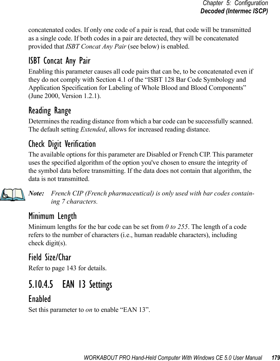
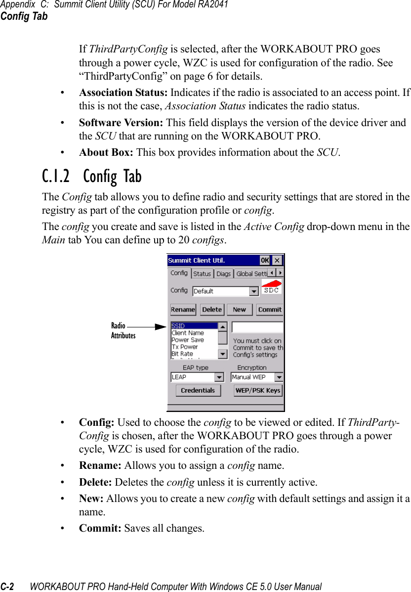
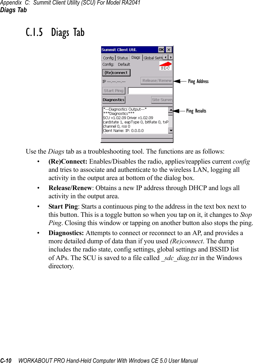
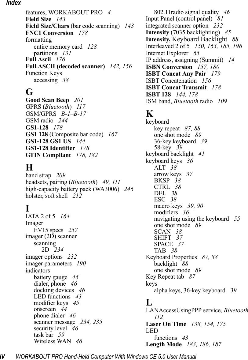
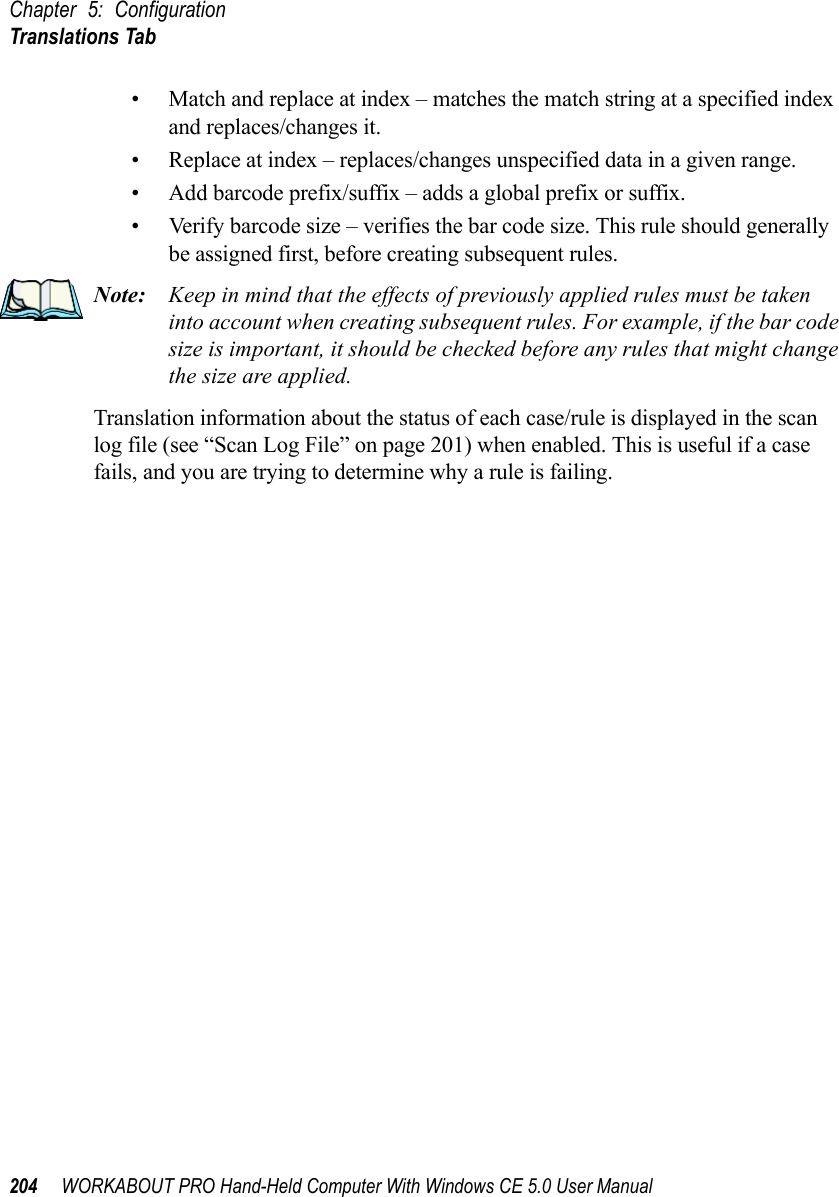
![WORKABOUT PRO Hand-Held Computer With Windows CE 5.0 User Manual 189Chapter 5: ConfigurationDecoded (Intermec ISCP)Field Size/CharRefer to page 143 for details.5.10.4.20 Micro PDF-417EnabledSet this parameter to on to enable “Micro PDF-417”.Code 128 EmulationWhen this parameter is enabled, the scanner transmits data from certain Micro PDF-417 symbols as if it was encoded in Code 128 symbols. If Code 128 Emulation is enabled, the following Micro PDF-417 symbols are transmitted with one of the following prefixes:]C1if the first codeword is 903-907, 912, 914, 915]C2if the first codeword is 908 or 909]C0if the first codeword is 910 or 911If Code 128 Emulation is set to off, the Micro PDF-417 symbols are transmitted with one of the following prefixes:]L3if the first codeword is 903-907, 912, 914, 915]L4if the first codeword is 908 or 909]L5if the first codeword is 910 or 911Field Size/CharRefer to page 143 for details.5.10.4.21 CodablockEnable Codablock ASet this parameter to on to enable “Codablock type A”.Enable Codablock FSet this parameter to on to enable “Codablock type F”.Field Size/CharRefer to page 143 for details.](https://usermanual.wiki/Psion/7527CBTRA2041M.Revised-user-manual-part-3/User-Guide-852839-Page-27.png)
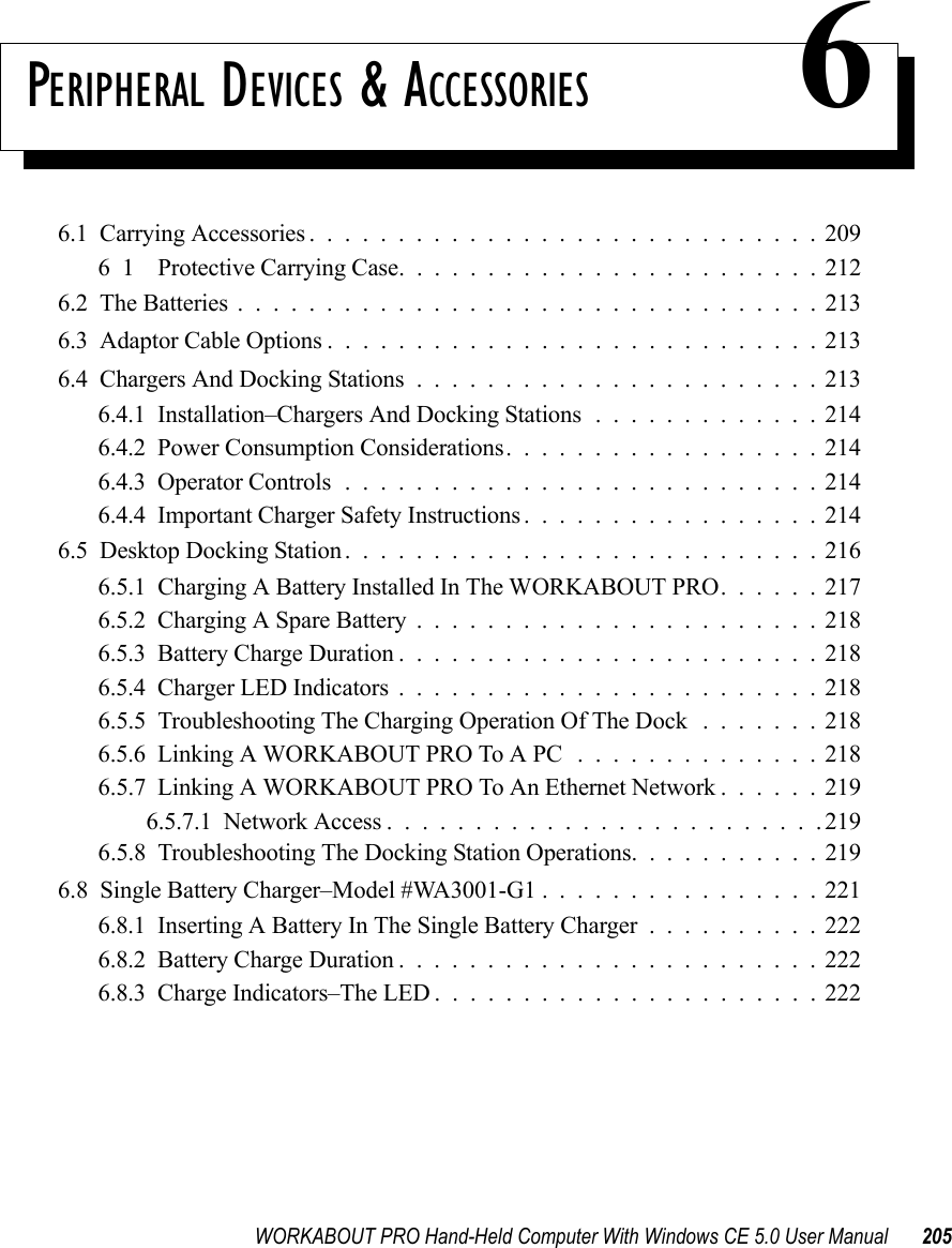
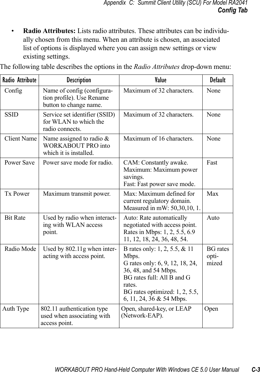
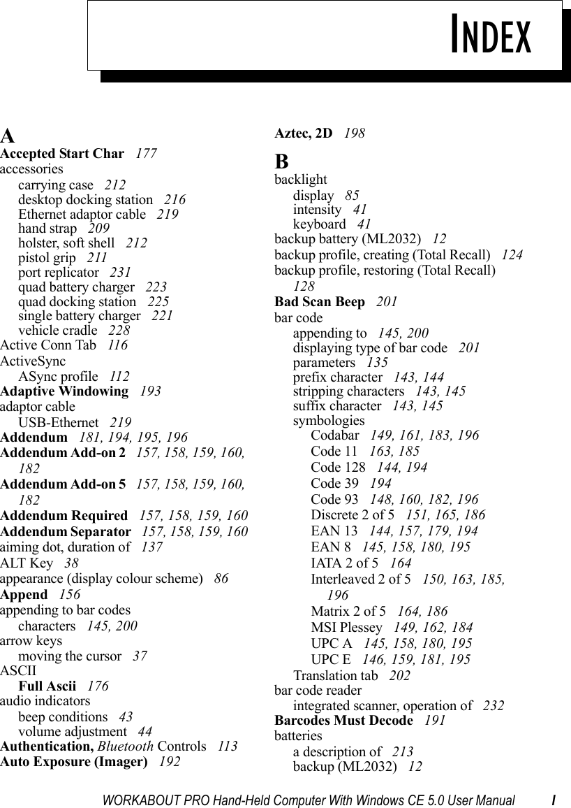
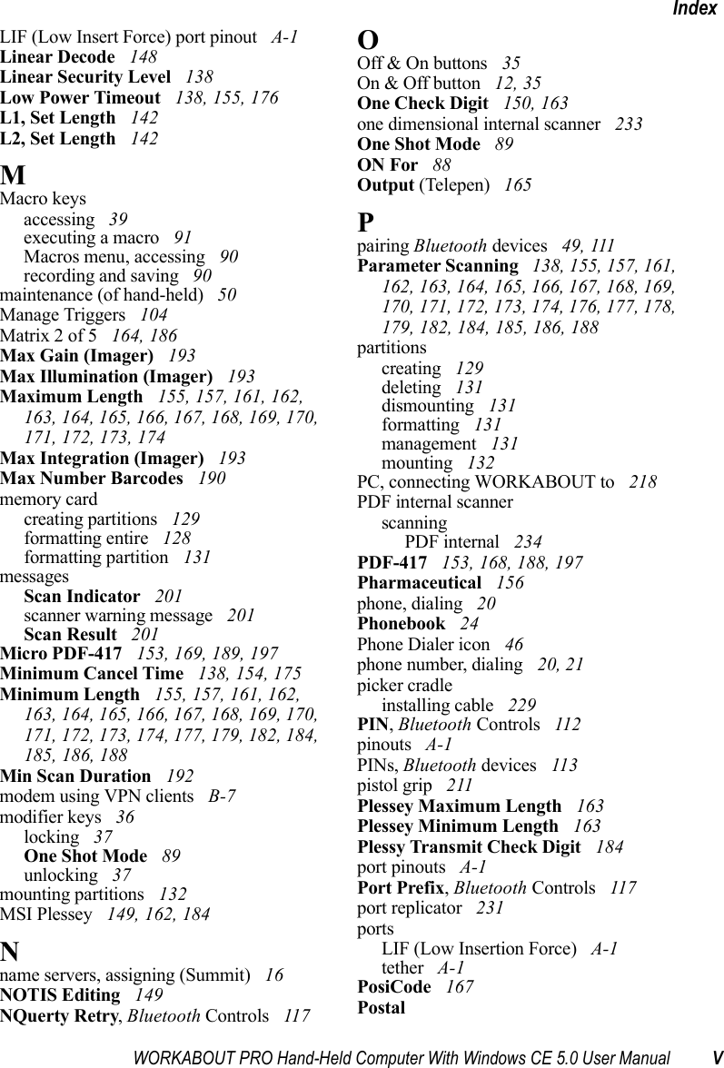
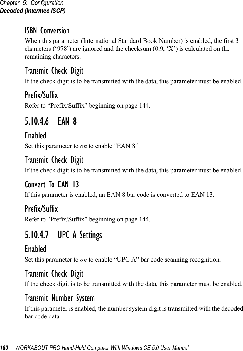
![Chapter 7: SpecificationsWORKABOUT PRO Specifications240 WORKABOUT PRO Hand-Held Computer With Windows CE 5.0 User ManualBar Code Applications• Optional 1D imager expansion module• Optional 2D imager expansion module• Optional 1D SE955 laser scanner expansion module• Optional 1D SE1223 High Performance laser scanner expansion module• Optional bolt-on pistol gripNote: All are user upgradeableRFID Modules• UHF module- Frequency: 902 MHz or 928 MHz- Read range: up to 4.92 ft.(150 cm) [915MHz] and up to 2.62 ft.(80 cm) [868 MHz]- Tag supported: EPC Class 1 Gen 2, other protocols depending on regionsUser Interface• Color Touch Screen Display 3.6 in.(9.144 cm) diagonal- Full VGA 480x640 resolution- Transflective, portrait mode TFT- Adjustable Backlight](https://usermanual.wiki/Psion/7527CBTRA2041M.Revised-user-manual-part-3/User-Guide-852839-Page-66.png)