Psion 7527CBTRA2041M Workabout Pro G2 User Manual 7535 G2 Hand Held Computer
Psion Inc Workabout Pro G2 7535 G2 Hand Held Computer
Psion >
Contents
- 1. Users manual 7527C
- 2. Revised users manual part 1
- 3. Revised users manual part 2
- 4. Revised user manual part 3
Revised user manual part 3
WORKABOUT PRO Hand-Held Computer With Windows CE 5.0 User Manual 163
Chapter 5: Configuration
Decoded (HHP)
Plessey Minimum And Plessey Maximum Length
These parameters apply to Plessey bar codes.The length of a code refers to the
number of characters (i.e., human readable characters), including check digit(s).
Double-tapping on these parameters displays a screen in which you can set the
minimum and maximum allowable code lengths – 4 to 48.
Field Size/Char
Refer to page 143 for details.
5.10.3.14 Code 11
Enabled
Set this parameter to on to enable “Code 11”.
Check Digits
Double-tapping on this parameter displays a dialog box in which you can choose
One Check Digit or Two check digits.
If this parameter is set to One Check Digit, it is assumed that the last digit is a check
digit. If it is set to Two Check Digits, it is assumed that the last two digits are check
digits.
Minimum And Maximum Length
The length of a code refers to the number of characters (i.e., human readable
characters), including check digit(s). Double-tapping on these parameters displays a
screen in which you can set the minimum and maximum allowable code lengths – 1
to 80.
Field Size/Char
Refer to page 143 for details.
5.10.3.15 Interleaved 2 of 5
Enabled
Set this parameter to on to enable “Interleaved 2 of 5”.
Chapter 5: Configuration
Decoded (HHP)
164 WORKABOUT PRO Hand-Held Computer With Windows CE 5.0 User Manual
Check Digit
When this parameter is set to Validate only, the integrity of a symbol is checked to
ensure that it complies with specified algorithms.
If “Check Digit” is set to Validate and Transmit, the check digit is validated and
transmitted with the data.
Setting this parameter to None disables this function.
Minimum And Maximum Length
The length of a code refers to the number of characters (i.e., human readable
characters), including check digit(s). Double-tapping on these parameters displays a
screen in which you can set the minimum and maximum allowable code lengths – 1
to 80.
Field Size/Char
Refer to page 143 for details.
5.10.3.16 Matrix 2 of 5
Enabled
Set this parameter to on to enable “Matrix 2 of 5”.
Minimum And Maximum Length
The length of a code refers to the number of characters (i.e., human readable
characters), including check digit(s). Double-tapping on these parameters displays a
screen in which you can set the minimum and maximum allowable code lengths – 1
to 80.
Field Size/Char
Refer to page 143 for details.
5.10.3.17 IATA 2 of 5
Enabled
Set this parameter to on to enable “IATA 2 of 5”.
WORKABOUT PRO Hand-Held Computer With Windows CE 5.0 User Manual 165
Chapter 5: Configuration
Decoded (HHP)
Minimum And Maximum Length
The length of a code refers to the number of characters (i.e., human readable
characters), including check digit(s). Double-tapping on these parameters displays a
screen in which you can set the minimum and maximum allowable code lengths – 1
to 48.
Field Size/Char
Refer to page 143 for details.
5.10.3.18 Discrete 2 of 5
Enabled
Set this parameter to on to enable “Discrete 2 of 5”.
Minimum And Maximum Length
The length of a code refers to the number of characters (i.e., human readable
characters), including check digit(s). Double-tapping on these parameters displays a
screen in which you can set the minimum and maximum allowable code lengths – 1
to 48.
Field Size/Char
Refer to page 143 for details.
5.10.3.19 Telepen
Enabled
Set this parameter to on to enable “Telepen”.
Output
If you choose AIM Output, the imager reads symbols with start/stop pattern 1 and
decodes them as standard full ASCII (start/stop pattern 1). If you choose Original
Output, the imager reads symbols with start/stop pattern 1 and decodes them as
compressed numeric with optional full ASCII (start/stop pattern 2).
Chapter 5: Configuration
Decoded (HHP)
166 WORKABOUT PRO Hand-Held Computer With Windows CE 5.0 User Manual
Minimum And Maximum Length
The length of a code refers to the number of characters (i.e., human readable
characters), including check digit(s). Double-tapping on these parameters displays a
screen in which you can set the minimum and maximum allowable code lengths – 1
to 60.
Field Size/Char
Refer to page 143 for details.
5.10.3.20 RSS Code (Reduced Space Symbology)
Enable
Setting this parameter to on enables “RSS Code” scanning capability.
Enable RSS Limited
‘RSS-Limited” is restricted, in that it can only encode 14 digit GTINs (global trade
item number) that begin with either a 0 or a 1. It is not stackable and is not designed
to be read omni-directionally.
Enable RSS Expanded
“RSS Expanded” uses the same application identifiers as UCC/EAN-128 codes but
they can be split into sections and stacked several rows high, reducing the length of
the symbol, while increasing the capacity of data that can be stored. “RSS
Expanded” code can be omni-directionally scanned.
Minimum And Maximum Length
The length of a code refers to the number of characters (i.e., human readable
characters), including check digit(s). Double-tapping on these parameters displays a
screen in which you can set the minimum and maximum allowable code lengths – 1
to 74.
Field Size/Char
Refer to page 143 for details.

WORKABOUT PRO Hand-Held Computer With Windows CE 5.0 User Manual 167
Chapter 5: Configuration
Decoded (HHP)
5.10.3.21 PosiCode (Reduced Space Symbology)
Enable
Setting this parameter to on enables “PosiCode” scanning capability.
PosiCode
“PosiCode” is a “position” based symbology. A position based symbology
de-couples the widths of the bars from their positions. The centers of the bars are
specified to be laid out on a grid of equally spaced parallel lines. The distance
between these grid lines is called the G-dimension and is analogous to the
X-dimension of conventional bar codes.
There are two variations of this code: PosiCode A, and PosiCode B. The options
available with this parameter allow to choose A and B, A and B and Limited A or A
and B and Limited B.
Minimum And Maximum Length
The length of a code refers to the number of characters (i.e., human readable
characters), including check digit(s). Double-tapping on these parameters displays a
screen in which you can set the minimum and maximum allowable code lengths – 1
to 80.
Field Size/Char
Refer to page 143 for details.
5.10.3.22 Composite
Important: To successfully read this type of bar code, the two types of
symbologies included in a composite bar code must be enabled.
A composite symbol includes multi-row 2D components making it compatible with
linear and area CCD scanners along with linear and rastering laser scanners.
The options available for this parameter represent multi-level components of a
composite symbol.
GS1 128
“GS1 128” is the GS1 implementation of the Code 128 barcode specification. The
former correct name was UCC/EAN-128.
Chapter 5: Configuration
Decoded (HHP)
168 WORKABOUT PRO Hand-Held Computer With Windows CE 5.0 User Manual
“GS1-128” uses a series of Application Identifiers to include additional data such as
best before dates, batch numbers, quantities, weights and many other attributes
needed by the user.
EAN/UCC 128 Emulation
The options in this parameter allow you to turn this emulation on or off, or to enable
RSS Emulation.
Minimum And Maximum Length
The length of a code refers to the number of characters (i.e., human readable
characters), including check digit(s). Double-tapping on these parameters displays a
screen in which you can set the minimum and maximum allowable code lengths – 1
to 2435.
5.10.3.23 TLC-39
This composite component integrates MicroPDF417 with the linear code.
Enabled
Setting this parameter to on enables this parameter.
Field Size/Char
Refer to page 143 for details.
5.10.3.24 PDF-417
Enabled
Set this parameter to on to enable “PDF-417”.
Minimum And Maximum Length
The length of a code refers to the number of characters (i.e., human readable
characters), including check digit(s). Double-tapping on these parameters displays a
screen in which you can set the minimum and maximum allowable code lengths – 1
to 2750.
Field Size/Char
Refer to page 143 for details.
WORKABOUT PRO Hand-Held Computer With Windows CE 5.0 User Manual 169
Chapter 5: Configuration
Decoded (HHP)
5.10.3.25 Micro PDF-417
Enabled
Set this parameter to on to enable “Micro PDF-417”.
Minimum And Maximum Length
The length of a code refers to the number of characters (i.e., human readable
characters), including check digit(s). Double-tapping on these parameters displays a
screen in which you can set the minimum and maximum allowable code lengths – 1
to 366.
Field Size/Char
Refer to page 143 for details.
5.10.3.26 Code 16K
The “Code 16K” bar code is a multiple-row bar code that can encode the full ASCII
character set below ASCII 128. It uses existing UPC and Code 128 character set
patterns. Up to 77 full ASCII characters or 154 numeric characters can be encoded
into 2 to 16 rows. Each row is divided by a separator bar. The top and bottom of the
symbol also have separator bars that extend to the ends of the minimum quiet zones.
Enabled
Set this parameter to on to enable “Code 16K”.
Minimum And Maximum Length
The length of a code refers to the number of characters (i.e., human readable
characters), including check digit(s). Double-tapping on these parameters displays a
screen in which you can set the minimum and maximum allowable code lengths – 1
to 160.
Field Size/Char
Refer to page 143 for details.
Chapter 5: Configuration
Decoded (HHP)
170 WORKABOUT PRO Hand-Held Computer With Windows CE 5.0 User Manual
5.10.3.27 Code 49
The “Code 49” bar code is a multiple-row bar code that can encode the full ASCII
character set below ASCII 128. Up to 49 alphanumeric characters or 81 numeric
characters can be encoded into two to eight rows. Each row is divided by a separator
bar. The top and bottom of the symbol also have separator bars that extend to the
ends of the minimum quiet zones.
Enabled
Set this parameter to on to enable “Code 49”.
Minimum And Maximum Length
The length of a code refers to the number of characters (i.e., human readable
characters), including check digit(s). Double-tapping on these parameters displays a
screen in which you can set the minimum and maximum allowable code lengths – 1
to 81.
Field Size/Char
Refer to page 143 for details.
5.10.3.28 Codablock
Enable
Set this parameter to on to enable “Codablock”.
Minimum And Maximum Length
The length of a code refers to the number of characters (i.e., human readable
characters), including check digit(s). Double-tapping on these parameters displays a
screen in which you can set the minimum and maximum allowable code lengths – 1
to 2048.
Field Size/Char
Refer to page 143 for details.
5.10.3.29 2D Data Matrix
Enable
Set this parameter to on to enable “2D Data Matrix”.
WORKABOUT PRO Hand-Held Computer With Windows CE 5.0 User Manual 171
Chapter 5: Configuration
Decoded (HHP)
Minimum And Maximum Length
The length of a code refers to the number of characters (i.e., human readable
characters), including check digit(s). Double-tapping on these parameters displays a
screen in which you can set the minimum and maximum allowable code lengths – 1
to 1500.
Field Size/Char
Refer to page 143 for details.
5.10.3.30 2D QR Code
Enabled
Set this parameter to on to enable “2D QR Code”.
Minimum And Maximum Length
The length of a code refers to the number of characters (i.e., human readable
characters), including check digit(s). Double-tapping on these parameters displays a
screen in which you can set the minimum and maximum allowable code lengths – 1
to 3500.
Field Size/Char
Refer to page 143 for details.
5.10.3.31 2D Maxicode
Enabled
Set this parameter to on to enable “2D Maxicode”.
Minimum And Maximum Length
The length of a code refers to the number of characters (i.e., human readable
characters), including check digit(s). Double-tapping on these parameters displays a
screen in which you can set the minimum and maximum allowable code lengths – 1
to 150.
Field Size/Char
Refer to page 143 for details.
Chapter 5: Configuration
Decoded (HHP)
172 WORKABOUT PRO Hand-Held Computer With Windows CE 5.0 User Manual
5.10.3.32 2D Aztec
Enabled
Set this parameter to on to enable “2D Aztec”.
Aztec Runes
Aztec Runes, the smallest type of Aztec Code symbol, has the ability to encode a
very short license plate message.
Minimum And Maximum Length
The length of a code refers to the number of characters (i.e., human readable
characters), including check digit(s). Double-tapping on these parameters displays a
screen in which you can set the minimum and maximum allowable code lengths – 1
to 3750.
Field Size/Char
Refer to page 143 for details.
5.10.3.33 Postal: PlaNET
Enabled
Set this parameter to on to enable “Postal: PlaNET”.
Check Digit
If enabled, the check digit will be transmitted at the end of the scanned data.
Field Size/Char
Refer to page 143 for details.
5.10.3.34 Postal: PostNET
Enabled
Set this parameter to on to enable “Postal: PostNET”.
Check Digit
If enabled, the check digit will be transmitted at the end of the scanned data.
WORKABOUT PRO Hand-Held Computer With Windows CE 5.0 User Manual 173
Chapter 5: Configuration
Decoded (HHP)
Field Size/Char
Refer to page 143 for details.
5.10.3.35 Postal: Australian
Enabled
Set this parameter to on to enable “Postal: Australian”.
Field Size/Char
Refer to page 143 for details.
5.10.3.36 Postal: Canadian
Enabled
Set this parameter to on to enable “Postal: Canadian”.
Field Size/Char
Refer to page 143 for details.
5.10.3.37 Postal: China
Enabled
Set this parameter to on to enable “Postal: China”.
Minimum And Maximum Length
The length of a code refers to the number of characters (i.e., human readable
characters), including check digit(s). Double-tapping on these parameters displays a
screen in which you can set the minimum and maximum allowable code lengths – 2
to 80.
Field Size/Char
Refer to page 143 for details.
5.10.3.38 Postal: Japanese
Enabled
Set this parameter to on to enable “Postal: Japanese”.
Chapter 5: Configuration
Decoded (HHP)
174 WORKABOUT PRO Hand-Held Computer With Windows CE 5.0 User Manual
Field Size/Char
Refer to page 143 for details.
5.10.3.39 Postal: Kix
Enabled
Set this parameter to on to enable “Postal: Kix”.
Field Size/Char
Refer to page 143 for details.
5.10.3.40 Postal: Korean
Enabled
Set this parameter to on to enable “Postal: Korean”.
Minimum And Maximum Length
The length of a code refers to the number of characters (i.e., human readable
characters), including check digit(s). Double-tapping on these parameters displays a
screen in which you can set the minimum and maximum allowable code lengths – 2
to 48.
Field Size/Char
Refer to page 143 for details.
5.10.3.41 Postal: Royal
Enabled
Set this parameter to on to enable “Postal: Royal”.
Field Size/Char
Refer to page 143 for details.
WORKABOUT PRO Hand-Held Computer With Windows CE 5.0 User Manual 175
Chapter 5: Configuration
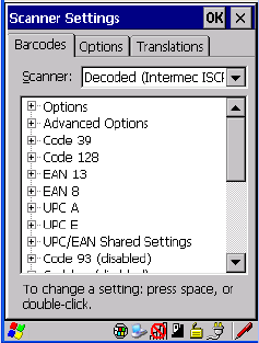
Decoded (Intermec ISCP)
5.10.4 Decoded (Intermec ISCP)
• Tap on the Scanner drop-down menu, and choose Decoded (Intermec
ISCP).
5.10.4.1 Decoded (Intermec ISCP) Options
Laser On Time
The value assigned to this parameter determines how long the laser will remain on
when the scan button or trigger is pressed.
Double-tapping on this parameter displays a dialog box in which you can enter a
value between 1 and 10 seconds.
5.10.4.2 Decoded (Intermec ISCP) Advanced Options
Continuous Scan Mode
Setting this parameter to ‘on’ keeps the laser on and continuously decoding as long
as the scanner button is pressed and held down.
Minimum Cancel Time
The value assigned to this parameter determines the time delay before the scanner is
turned off, once the scanner trigger or button is released. This gives the scanner a
minimum amount of time to complete its current decode before the scan is cancelled
when the user quickly triggers on/off.

Chapter 5: Configuration
Decoded (Intermec ISCP)
176 WORKABOUT PRO Hand-Held Computer With Windows CE 5.0 User Manual
Low Power Timeout
To extend laser life, you can select the length of time the scanner remains active
following a successful decode. The scanner wakes from low power mode when a
bar code is scanned – a successful decode restores normal blinking.
When you double-tap on this parameter, a dialog box is displayed in which you can
choose a value of 30 sec, 1 min, 2 min or 3 min.
Note: This parameter is only used if the Trigger Mode has been set to Continu-
ous On and the hand-held is mounted in a fixed position; otherwise, ‘Low
Power Timeout’ is not used.
Parameter Scanning
Setting this parameter to Enabled allows decoding of parameter bar codes.
Same Read Validate
The data is only transmitted after repeated reads give the same result. The
value assigned at this parameter determines the number of reads required, from
0 to 10 times.
Same Read Timeout
Prevents the same bar code from being read more than once. The value assigned
determines after what time period the scanner will timeout, from 0 to 2550 msec.
Diff Read Timeout
Prevents unwanted reading of other bar codes on the same label. The value assigned
determines after what time period the scanner will timeout, from 0 to 2550 msec.
5.10.4.3 Code 39
Enable
Setting this parameter to on enables “Code 39”.
Full ASCII
If this parameter is enabled, the characters +, %, and / are used as escape
characters. The combination of an escape character and the next character
is converted to an equivalent ASCII character.

WORKABOUT PRO Hand-Held Computer With Windows CE 5.0 User Manual 177
Chapter 5: Configuration
Decoded (Intermec ISCP)
Reading Range
Determines the reading distance from which a bar code can be successfully scanned.
The default setting, Extended, allows for increased reading distance.
Start/Stop Transmit
Setting this parameter to on enables the transmission of start and stop characters,
which are usually not transmitted. Code 39 can start and end with either a * or a $
character (see also next parameter Accepted Start Char).
Accepted Start Char
This parameter allows the user the option of using one of the two start/stop
characters or both ($ char, * char, $ and * char).
Check Digit Verification
Uses the specified algorithm of the option you've chosen to ensure the integrity of
the symbol data before transmitting. If the data does not contain that algorithm, the
data is not transmitted. The available options are: Disabled, MOD 43 Check, French
CIP, or Italian CIP.
Notes: French CIP (French pharmaceutical) is only used with bar codes contain-
ing 7 characters.
Italian CIP (Italian pharmaceutical) is also known as Code 32. It is trans-
mitted as a standard Code 39 if checksum is not validated.
Transmit Check Digit
If the check digit is to be transmitted with the data, this parameter must be enabled.
Minimum Length
Minimum lengths for the bar code can be set from 0 to 255. The length of a code
refers to the number of characters (i.e., human readable characters), including check
digit(s).
Field Size/Char
Refer to page 143 for details.

Chapter 5: Configuration
Decoded (Intermec ISCP)
178 WORKABOUT PRO Hand-Held Computer With Windows CE 5.0 User Manual
5.10.4.4 Code 128
Enable
Setting this parameter to on enables “Code 128”.
GS1-128
“GS1-128” is the GS1 implementation of the Code 128 barcode specification. The
former correct name was UCC/EAN-128.
GS1-128 Identifier
“GS1-128 Identifier” allows the AIM ID " ]C1" for EAN 128 to be transmitted or
removed. By default, this identifier is transmitted if EAN 128 is enabled.
GTIN Compliant
GTIN (global trade item number) processing transmits EAN 128 as the 14-character
EAN/UCC GTIN. To use GTIN processing, you must activate the EAN 128
symbology.
Important: When EAN 128 and GTIN processing are both activated, it is not
possible to read normal EAN 128 Codes.
FNC1 Conversion
“FNC1 Conversion” allows the FNC1 character to be converted to another character
for applications that cannot use the default <GS> Group Separator or hex (1d).
Double-tapping on this option displays a dialog box listing the allowable
range – 0 to 255.
Enable ISBT 128
To successfully scan this type of bar code (International Society of Blood
Transfusion), this option must be set to on. If you enable this type of bar code, Code
128/EAN 128 is deactivated to avoid any confusion.
ISBT Concat Transmit
The codes are not concatenated by default. You need to choose one of the options
provided for this parameter to send concatenated code. Choosing Only
Concatenated Codes transmits only concatenated codes—single codes will not be
transmitted. Choosing Concatenated or Single transmits single codes or

WORKABOUT PRO Hand-Held Computer With Windows CE 5.0 User Manual 179
Chapter 5: Configuration
Decoded (Intermec ISCP)
concatenated codes. If only one code of a pair is read, that code will be transmitted
as a single code. If both codes in a pair are detected, they will be concatenated
provided that ISBT Concat Any Pair (see below) is enabled.
ISBT Concat Any Pair
Enabling this parameter causes all code pairs that can be, to be concatenated even if
they do not comply with Section 4.1 of the “ISBT 128 Bar Code Symbology and
Application Specification for Labeling of Whole Blood and Blood Components”
(June 2000, Version 1.2.1).
Reading Range
Determines the reading distance from which a bar code can be successfully scanned.
The default setting Extended, allows for increased reading distance.
Check Digit Verification
The available options for this parameter are Disabled or French CIP. This parameter
uses the specified algorithm of the option you've chosen to ensure the integrity of
the symbol data before transmitting. If the data does not contain that algorithm, the
data is not transmitted.
Note: French CIP (French pharmaceutical) is only used with bar codes contain-
ing 7 characters.
Minimum Length
Minimum lengths for the bar code can be set from 0 to 255. The length of a code
refers to the number of characters (i.e., human readable characters), including
check digit(s).
Field Size/Char
Refer to page 143 for details.
5.10.4.5 EAN 13 Settings
Enabled
Set this parameter to on to enable “EAN 13”.
Chapter 5: Configuration
Decoded (Intermec ISCP)
180 WORKABOUT PRO Hand-Held Computer With Windows CE 5.0 User Manual
ISBN Conversion
When this parameter (International Standard Book Number) is enabled, the first 3
characters (‘978’) are ignored and the checksum (0.9, ‘X’) is calculated on the
remaining characters.
Transmit Check Digit
If the check digit is to be transmitted with the data, this parameter must be enabled.
Prefix/Suffix
Refer to “Prefix/Suffix” beginning on page 144.
5.10.4.6 EAN 8
Enabled
Set this parameter to on to enable “EAN 8”.
Transmit Check Digit
If the check digit is to be transmitted with the data, this parameter must be enabled.
Convert To EAN 13
If this parameter is enabled, an EAN 8 bar code is converted to EAN 13.
Prefix/Suffix
Refer to “Prefix/Suffix” beginning on page 144.
5.10.4.7 UPC A Settings
Enabled
Set this parameter to on to enable “UPC A” bar code scanning recognition.
Transmit Check Digit
If the check digit is to be transmitted with the data, this parameter must be enabled.
Transmit Number System
If this parameter is enabled, the number system digit is transmitted with the decoded
bar code data.
WORKABOUT PRO Hand-Held Computer With Windows CE 5.0 User Manual 181
Chapter 5: Configuration
Decoded (Intermec ISCP)
Convert To EAN 13
If this parameter is enabled, a UPC A bar code is converted to EAN 13.
Prefix/Suffix
Refer to “Prefix/Suffix” beginning on page 144.
5.10.4.8 UPC E Settings
Enabled
Set this parameter to on to enable “UPC E”.
Enable UPC-E1
Set this parameter to on to allow “UPC-E1” (zero suppressed) bar code scans.
Transmit Check Digit
If the check digit is to be transmitted with the data, this parameter must be enabled.
Transmit Number System
If this parameter is enabled, the number system digit is transmitted with the decoded
bar code data.
Convert To UPC-A
This parameter converts UPC E (zero suppressed) decoded data to UPC A format
before transmission. After conversion, data follows UPC A format and is affected
by UPC A programming selections (e.g. Check Digit).
Prefix/Suffix
Refer to “Prefix/Suffix” beginning on page 144.
5.10.4.9 UPC/EAN Shared Settings
The setting assigned to the “Addendum” parameter associated with this option is
shared across all UPC and EAN bar codes.
Addendum
An addendum is a separate bar code, supplementary to the main bar code.
This parameter provides two options: Not Required but Transmitted if Read or
Required and Transmitted.

Chapter 5: Configuration
Decoded (Intermec ISCP)
182 WORKABOUT PRO Hand-Held Computer With Windows CE 5.0 User Manual
• Double-tap on Addendum to display a dialog box listing your options.
• Highlight an item, and tap on OK.
When “Addendum” is set to Not Required but Transmitted if Read, the scanner
searches for an addendum and if one exists, appends it to the main bar code. When
the parameter is set to Required and Transmitted, the scanner does not accept the
main bar code without an addendum.
Addendum Add-on 2 And Addendum Add-on 5
Enabling these parameters sets the length of the addendum bar code to either 2 or
5 characters.
GTIN Compliant
GTIN (global trade item number) processing transmits EAN 128 as the 14-character
EAN/UCC GTIN. To use GTIN processing, you must activate the EAN 128
symbology.
Important: When EAN 128 and GTIN processing are both activated, it is not
possible to read normal EAN 128 Codes.
Reading Range
This parameter determines the reading distance from which a bar code can be
successfully scanned. The default setting, Extended, allows for increased
reading distance.
5.10.4.10 Code 93
Enabled
Set this parameter to on to enable “Code 93”.
Minimum Length
Minimum lengths for the bar code can be set from 0 to 255. The length of a code
refers to the number of characters (i.e., human readable characters), including
check digit(s).
Field Size/Char
Refer to page 143 for details.
WORKABOUT PRO Hand-Held Computer With Windows CE 5.0 User Manual 183
Chapter 5: Configuration
Decoded (Intermec ISCP)
5.10.4.11 Codabar
Enabled
Set this parameter to on to enable “Codabar”.
Start/Stop Transmit
Codabar can use the following sets of characters as start and stop characters:
a, b, c, d
A, B, C, D
a, b, c, d, /, t, n, *, e
DC1, DC2, DC3, DC4
Thus, when a set is chosen, the first and last digits of a Codabar message must be
one of those characters and the body of the message should not contain these
characters. Setting this parameter to Not Transmitted strips the start and stop
characters from this bar code.
CLSI Library System
When enabled, spaces are inserted after characters 1, 5, 10 in the 14-character label
(used in the USA by libraries using the CLSI system).
Check Digit Verification
When enabled, this parameter checks the integrity of a symbol to ensure it complies
with a specified algorithm – either USS (Uniform Symbology Specification) or
OPCC (Optical Product Code Council).
Transmit Check Digit
If the check digit is to be transmitted with the data, this parameter must be enabled.
Set Length L1, Set Length L2, And Set Length L3
Lengths for “Codabar” can be set from 0 to 255. The length of a code refers to the
number of characters (i.e., human readable characters), including check digit(s).
Double-tapping on these parameters displays dialog boxes where you can define the
code length that will be recognized by your scanner.
Length Mode
You can choose to set L1 as Minimum Length or L1,L2,L3 as Fixed Length.
Chapter 5: Configuration
Decoded (Intermec ISCP)
184 WORKABOUT PRO Hand-Held Computer With Windows CE 5.0 User Manual
Field Size/Char
Refer to page 143 for details.
5.10.4.12 MSI Plessey
Enabled
Set this parameter to on to enable “MSI”.
Enable Plessy
Set this parameter to on to enable “Plessy”.
Check Digit Verification
The available options for this parameter are MOD 10 Check and Double MOD 10
Check. This parameter uses the specified algorithm of the option you've chosen to
ensure the integrity of the symbol data before transmitting. If the data does not
contain that algorithm, the data is not transmitted.
Transmit Check Digit
If the check digit is to be transmitted with the data, this parameter must be enabled.
Plessy Transmit Check Digit
If the check digit is to be transmitted with the Plessy data, this parameter must
be enabled.
Minimum Length
Minimum lengths for the bar code can be set from 0 to 255. The length of a code
refers to the number of characters (i.e., human readable characters), including
check digit(s).
Plessy Minimum Length
Minimum lengths for the Plessy bar code can be set from 0 to 255. The length of a
code refers to the number of characters (i.e., human readable characters), including
check digit(s).
Field Size/Char
Refer to page 143 for details.
WORKABOUT PRO Hand-Held Computer With Windows CE 5.0 User Manual 185
Chapter 5: Configuration
Decoded (Intermec ISCP)
5.10.4.13 Code 11
Enabled
Set this parameter to on to enable “Code 11”.
Check Digit Verification
The available options for this parameter are MOD 10 Check and Double MOD 10
Check.This parameter uses the specified algorithm of the option you've chosen to
ensure the integrity of the symbol data before transmitting. If the data does not
contain that algorithm, the data is not transmitted.
Transmit Check Digit
If the check digit is to be transmitted with the data, this parameter must be enabled.
Minimum Length
Minimum lengths for the bar code can be set from 0 to 255. The length of a code
refers to the number of characters (i.e., human readable characters), including
check digit(s).
Field Size/Char
Refer to page 143 for details.
5.10.4.14 Interleaved 2 of 5
Enabled
Set this parameter to on to enable “Interleaved 2 of 5”.
Reading Range
This parameter determines the reading distance from which a bar code can be
successfully scanned. The default setting, Extended, allows for increased
reading distance.
Check Digit Verification
The available options for this parameter are Disabled, MOD 10 Check and French
CIP. “Check Digit Verification” uses the specified algorithm of the option you've
chosen to ensure the integrity of the symbol data before transmitting. If the data does
not contain that algorithm, the data is not transmitted.

Chapter 5: Configuration
Decoded (Intermec ISCP)
186 WORKABOUT PRO Hand-Held Computer With Windows CE 5.0 User Manual
Note: French CIP (French pharmaceutical) is only used with bar codes contain-
ing 7 characters.
Transmit Check Digit
If the check digit is to be transmitted with the data, this parameter must be enabled.
Set Length L1, Set Length L2, And Set Length L3
Lengths for “Interleaved 2 of 5” can be set from 0 to 255. The length of a code
refers to the number of characters (i.e., human readable characters), including
check digit(s).
Double-tapping on these parameters displays dialog boxes where you can define the
code length that will be recognized by your scanner.
Length Mode
You can chose to set L1 as Minimum Length or L1,L2,L3 as Fixed Length.
Field Size/Char
Refer to page 143 for details.
5.10.4.15 Matrix 2 of 5
Enabled
Set this parameter to on to enable “Matrix 2 of 5”.
Minimum Length
Minimum lengths for the bar code can be set from 0 to 255. The length of a code
refers to the number of characters (i.e., human readable characters), including
check digit(s).
Field Size/Char
Refer to page 143 for details.
5.10.4.16 Discrete 2 of 5
Enabled
Set this parameter to on to enable “Discrete 2 of 5”.
WORKABOUT PRO Hand-Held Computer With Windows CE 5.0 User Manual 187
Chapter 5: Configuration
Decoded (Intermec ISCP)
Standard 2 of 5 Format
This parameter allows you to choose a standard format – either Identicon (6
start/stop bars) or Computer Identics (4 start/stop bars).
Check Digit Verification
The available options for this parameter are Disabled and MOD 10 Check. “Check
Digit Verification” uses the specified algorithm of the option you've chosen to
ensure the integrity of the symbol data before transmitting. If the data does not
contain that algorithm, the data is not transmitted.
Transmit Check Digit
If the check digit is to be transmitted with the data, this parameter must be enabled.
Set Length L1, Set Length L2, And Set Length L3
Lengths for “Discrete 2 of 5” can be set from 0 to 255. The length of a code refers to
the number of characters (i.e., human readable characters), including check digit(s).
Double-tapping on these parameters displays dialog boxes where you can define the
code length that will be recognized by your scanner.
Length Mode
You can chose to set L1 as Minimum Length or L1,L2,L3 as Fixed Length.
Field Size/Char
Refer to page 143 for details.
5.10.4.17 Telepen
Enabled
Set this parameter to on to enable “Telepen”.
Format
This parameter allows you to set the bar code character format to either ASCII
or Numeric.
Chapter 5: Configuration
Decoded (Intermec ISCP)
188 WORKABOUT PRO Hand-Held Computer With Windows CE 5.0 User Manual
Minimum Length
Minimum lengths for the bar code can be set from 0 to 255. The length of a code
refers to the number of characters (i.e., human readable characters), including
check digit(s).
Field Size/Char
Refer to page 143 for details.
5.10.4.18 RSS Code (Reduced Space Symbology)
Enable
Setting this parameter to on enables “RSS Code” scanning capability.
Enable RSS-14
RSS-14 code can be either purely linear or split in half with one half stacked on top
of the other half. Stacking the code reduces the bar code length, and providing the
nominal height of the code is maintained, it can be omni-directionally scanned.
Enable RSS Limited
“RSS-Limited” is restricted, in that it can only encode 14 digit GTINs (global trade
item number) that begin with either a 0 or a 1. It is not stackable and is not designed
to be read omni-directionally.
Enable RSS Expanded
“RSS Expanded” uses the same application identifiers as UCC/EAN-128 codes but
they can be split into sections and stacked several rows high, reducing the length of
the symbol, while increasing the capacity of data that can be stored. “RSS
Expanded” code can be omni-directionally scanned.
Field Size/Char
Refer to page 143 for details.
5.10.4.19 PDF-417
Enabled
Set this parameter to on to enable “PDF-417”.
WORKABOUT PRO Hand-Held Computer With Windows CE 5.0 User Manual 189
Chapter 5: Configuration
Decoded (Intermec ISCP)
Field Size/Char
Refer to page 143 for details.
5.10.4.20 Micro PDF-417
Enabled
Set this parameter to on to enable “Micro PDF-417”.
Code 128 Emulation
When this parameter is enabled, the scanner transmits data from certain Micro
PDF-417 symbols as if it was encoded in Code 128 symbols.
If Code 128 Emulation is enabled, the following Micro PDF-417 symbols are
transmitted with one of the following prefixes:
]C1if the first codeword is 903-907, 912, 914, 915
]C2if the first codeword is 908 or 909
]C0if the first codeword is 910 or 911
If Code 128 Emulation is set to off, the Micro PDF-417 symbols are transmitted
with one of the following prefixes:
]L3if the first codeword is 903-907, 912, 914, 915
]L4if the first codeword is 908 or 909
]L5if the first codeword is 910 or 911
Field Size/Char
Refer to page 143 for details.
5.10.4.21 Codablock
Enable Codablock A
Set this parameter to on to enable “Codablock type A”.
Enable Codablock F
Set this parameter to on to enable “Codablock type F”.
Field Size/Char
Refer to page 143 for details.
Chapter 5: Configuration
Imager
190 WORKABOUT PRO Hand-Held Computer With Windows CE 5.0 User Manual
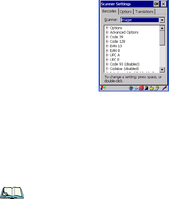
5.10.5 Imager
• Tap on the Scanner drop-down menu, and choose Imager.
5.10.5.1 Imager Options
TekImager Enabled
Setting this option to on enables the imager installed in your hand-held.
Continuous Scan Mode
Setting this parameter to on keeps image capture active and continuously decoding
as long as the scanner button is pressed and held down.
Center Bar Code Only
Note: This parameter must be disabled when reading Composite bar codes.
When more than one bar code is visible in a single snap shot, this parameter allows
you to specify that only the centre image within the imager framing marker be read.
When this parameter is set to on, the target dot is pointed at the centre image and
only that image is returned.
Max Number Barcodes
This parameter specifies the maximum number of bar codes the imager will attempt
to decode in an image. A maximum of 6 bar codes can be decoded at one time.

WORKABOUT PRO Hand-Held Computer With Windows CE 5.0 User Manual 191
Chapter 5: Configuration
Imager
Barcodes Must Decode
This parameter specifies the minimum number of bar codes that the imager must
decode in order to report success.
Note: This number must be less than the number of bar codes assigned to
“Max Number Barcodes”. The driver validates and reassigns the value
if necessary.
Window Width
“Window Width” determines the width of the captured image in pixels.
Note: The driver will validate and reassign the value assigned to this parameter,
if necessary; the driver will also use the Window Width value to horizon-
tally center the image in the field of view.
Window Height
This parameter determines the height of the captured image in pixels.
Note: The driver will validate and reassign the value assigned to this parameter,
if necessary; the driver will also use “Window Height” value to vertically
center the image in the field of view.
Dot Time (msec)
The value selected for “Dot Time (msec)” determines (in milliseconds) how long
the targeting dot remains on before the scanner begins capturing images. When you
double-tap on this parameter, a dialog box is displayed in which you can enter a
value of between 0 and 3000. A value of 0 disables the target dot.
5.10.5.2 Imager Advanced Options
Important: Do not adjust the advanced options without first consulting Psion
Teklogix technical support.
Factory Defaults On Reboot
The value assigned to this parameter determines whether or not the driver will
restore the factory defaults to the imager device on the next reboot.
Note: The driver will default the imager device on a ‘clean’ reset, regardless of
the value of this parameter.

Chapter 5: Configuration
Imager
192 WORKABOUT PRO Hand-Held Computer With Windows CE 5.0 User Manual
Min Scan Duration
This parameter defines the minimum amount of time in seconds that the imager will
scan when the trigger is pressed and held down without successful decode.
Note: The actual scan duration when the trigger is pressed relies on the value
assigned to Captures Per HW Trigger, below.
Captures Per HW Trigger
The value assigned to this parameter determines the number of captures the imager
device will take while the imager's internal hardware trigger is held down.
Note: This parameter, together with “Min Scan Duration”, determines the
actual scan duration. When the scan trigger is pressed and held down, the
driver starts a timer based on the value of “Min Scan Duration” and also
sends a command to emulate the hardware trigger. When completed, if the
time has not yet expired, it will send another command to the imager
device, forcing the imager to flash again using the value assigned to
“Captures Per HW Trigger”.
Auto Exposure
Important: This parameter value should only be changed by qualified Psion
Teklogix personnel. It should be left at the default value – ‘on’.
Setting this parameter to on allows the imager to make automatic gain, integration
and illumination adjustments based on ambient light before capturing the bar code.
If the adjustment is insufficient, further adjustments are made automatically before
another image is captured.
Fast Converge
Note: “Auto Exposure” must be set to ‘on’ in order for this parameter
to function.
Keep in mind that while this parameter can improve imager performance,
“Fast Converge” increases battery power consumption.
Setting this parameter to on speeds the “Auto Exposure” process. It allows the
imager to rapidly snap a number of bar code capture attempts while finding ideal
values for gain, integration and illumination.

WORKABOUT PRO Hand-Held Computer With Windows CE 5.0 User Manual 193
Chapter 5: Configuration
Imager
Max Gain, Max Integration And Max Illumination
Important: These parameter values should only be changed by qualified Psion
Teklogix personnel.
These parameters represent internal values used by the 2D imager. The “Auto
Exposure” parameter automatically adjusts the “Max Gain”, “Max Integration” and
“Max Illumination” parameters to produce the best bar code read. Keep in mind that
“Auto Exposure” must be set to on in order for these parameter values to be
automatically adjusted.
Double-tapping on any of these parameters displays an associated dialog box in
which an allowable range is displayed: Max Gain – 357 to 7920, Max Integration –
0 to 65535, Max Illumination – 0 to 7.
Decoder Timeout
The decoder is a set of algorithms that examine the image and attempt to find the bar
codes, and then turn the pixels into data that the computer can use—this process
takes time. “Decoder Timeout” limits the amount of time the decoder will spend
attempting to decode an image, and forces it to stop and grab a new image, which
will probably be easier to decode.
Note: When decoding multiple bar codes in one image, the value assigned to
‘Decoder Timeout’ should be increased to 200ms/extra bar code after the
first.
Adaptive Windowing
“Adaptive Windowing” is an advanced technique used to speed up bar code
recognition in certain applications. This parameter automatically reduces the size of
the window to the user-programmed window size when it successfully decodes
(which reduces decode time the next time it is used), but increases it to the full size
window (1280x1024 for SX5303) on a failed decode.
Note: This feature assumes that you have reached an understanding about how
the device operates in your application, and that, after a learning period,
operators will get used to using the imager in one particular way. It also
assumes that a trained operator will usually only have near miss scenar-
ios.
Chapter 5: Configuration
Imager
194 WORKABOUT PRO Hand-Held Computer With Windows CE 5.0 User Manual
Constant Illumination
“Constant Illumination” is used to reduce the intrusiveness of the device’s
illumination on the observer. Instead of the illumination turning on and off every
time the device attempts a decode (2-4 times per second), the illumination stays on
from the time the trigger is pulled until a decode is successful. This feature is useful
in low light environments, since it will also reduce the distraction that the
illumination can have on nearby co-workers.
5.10.5.3 Code 39 Settings
Enabled
Set this parameter to on to enable “Code 39”.
Field Size/Char
Refer to page 143 for details.
5.10.5.4 Code 128 Settings
Enabled
Set this parameter to on to enable “Code 128”.
Field Size/Char
Refer to page 143 for details.
5.10.5.5 EAN 13
Enabled
Set this parameter to on to enable “EAN 13”.
Addendum
An addendum is a separate bar code, supplementary to the main bar code.
This parameter provides three options: Disabled, Optional and Required.
Depending on the value chosen for this parameter, an addendum is recognized
or ignored.
• Double-tap on Addendum to display a dialog box listing your options.
• Highlight an item, and tap on OK.

WORKABOUT PRO Hand-Held Computer With Windows CE 5.0 User Manual 195
Chapter 5: Configuration
Imager
When “Addendum” is set to Disabled, the scanner does not recognize an
addendum. If this parameter is set to Optional, the scanner searches for
an addendum and if one exists, appends it to the main bar code. When the
parameter is set to Required, the scanner does not accept the main bar code
without an addendum.
Note: Setting “Addendum” to ‘Optional’ reduces performance. It should only
be chosen if at least some of the bar codes being read have addendums.
Prefix/Suffix
Refer to “Prefix/Suffix” beginning on page 144.
5.10.5.6 EAN 8
Enabled
Set this parameter to on to enable “EAN 8”.
Addendum
Refer to “Addendum” on page 194.
Prefix/Suffix
Refer to “Prefix/Suffix” beginning on page 144.
5.10.5.7 UPC A
Enabled
Set this parameter to on to enable “UPC A”.
Addendum
Refer to “Addendum” on page 194.
Prefix/Suffix
Refer to “Prefix/Suffix” beginning on page 144.
5.10.5.8 UPC E
Enabled
Set this parameter to on to enable “UPC E”.
Chapter 5: Configuration
Imager
196 WORKABOUT PRO Hand-Held Computer With Windows CE 5.0 User Manual
Addendum
Refer to “Addendum” on page 194.
Prefix/Suffix
Refer to “Prefix/Suffix” beginning on page 144.
5.10.5.9 Code 93
Enabled
Set this parameter to on to enable “Code 93”.
Field Size/Char
Refer to page 143 for details.
5.10.5.10 Codabar
Enabled
Set this parameter to on to enable “Codabar”.
Field Size/Char
Refer to page 143 for details.
5.10.5.11 Interleaved 2 of 5
Enabled
Set this parameter to on to enable “Interleaved 2 of 5”.
Field Size/Char
Refer to page 143 for details.
5.10.5.12 RSS Code (Reduced Space Symbology)
Enable
Setting this parameter to on enables “RSS Code” scanning capability.
Field Size/Char
Refer to page 143 for details.

WORKABOUT PRO Hand-Held Computer With Windows CE 5.0 User Manual 197
Chapter 5: Configuration
Imager
5.10.5.13 Composite
Important: To successfully read this type of bar code, the two types of symbolo-
gies included in a composite bar code must be enabled.
Enabled
Set this parameter to on to enable “Composite” bar codes.
5.10.5.14 PDF-417
Enable
Setting this parameter to on enables PDF-417 two dimensional (2D) coding.
Field Size/Char
Refer to page 143 for details.
5.10.5.15 Micro PDF-417
Enable
Setting this parameter to on enables “Micro PDF-417” bar code scanning. Micro
PDF-417 is a multi-row symbology that is useful for applications requiring greater
area efficiency but lower data capacity than PDF-417.
Field Size/Char
Refer to page 143 for details.
5.10.5.16 2D Data Matrix
Enable
Set this parameter to on to enable “Data Matrix”.
Field Size/Char
Refer to page 143 for details.
5.10.5.17 2D QR Code
Enabled
Set this parameter to on to enable “2D QR Code”.
Chapter 5: Configuration
Imager
198 WORKABOUT PRO Hand-Held Computer With Windows CE 5.0 User Manual
Field Size/Char
Refer to page 143 for details.
5.10.5.18 2D Maxicode
Enabled
Set this parameter to on to enable “2D Maxicode”.
Field Size/Char
Refer to page 143 for details.
5.10.5.19 2D Aztec
Enabled
Set this parameter to on to enable “Aztec”.
Field Size/Char
Refer to page 143 for details.
5.10.5.20 Postal: PlaNET
Enabled
Set this parameter to on to enable “Postal: PlaNET”.
Field Size/Char
Refer to page 143 for details.
5.10.5.21 Postal: PostNET
Enabled
Set this parameter to on to enable “Postal: PostNET”.
Field Size/Char
Refer to page 143 for details.
WORKABOUT PRO Hand-Held Computer With Windows CE 5.0 User Manual 199
Chapter 5: Configuration
Imager
5.10.5.22 Postal: Australian
Enabled
Set this parameter to on to enable “Postal: Australian”.
Field Size/Char
Refer to page 143 for details.
5.10.5.23 Postal: Japanese
Enabled
Set this parameter to on to enable “Postal: Japanese”.
Field Size/Char
Refer to page 143 for details.
5.10.5.24 Postal: Korean
Enabled
Set this parameter to on to enable “Postal: Korean”.
Field Size/Char
Refer to page 143 for details.
5.10.5.25 Postal: Royal
Enabled
Set this parameter to on to enable “Postal: Royal”.
Field Size/Char
Refer to page 143 for details.
Chapter 5: Configuration
Options
200 WORKABOUT PRO Hand-Held Computer With Windows CE 5.0 User Manual
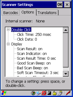
5.10.6 Options
This tab allows you to tailor the double-click parameters and the display options
associated with your scanner.
5.10.6.1 Double Click Parameters
Click Time (msec)
This parameter controls the maximum gap time (in milliseconds) for a double-click.
If the time between the first and second clicks of the scanner trigger is within this
time, it is considered a double-click. The allowable range is 0 to 1000. A value of
zero disables this feature.
A double-click produces different results depending on whether or not a value is
assigned in the “Click Data” parameter. When a value is not assigned for the “Click
Data”, double-clicking the scanner trigger overrides the target dot delay set in the
“Dot Time” parameter and initiates a normal scan sweep. If a value is assigned for
the “Click Data” parameter, double-clicking the scanner trigger inserts the “Click
Data” value rather than initiating a scan.
Click Data
For both integrated and external scanners, this parameter determines which
character is sent to the application installed in your hand-held following a
double-click. A dialog box appears, asking that you press the key you want to insert.
The ASCII/Unicode key value of the keypress is displayed.

WORKABOUT PRO Hand-Held Computer With Windows CE 5.0 User Manual 201
Chapter 5: Configuration
Options
5.10.6.2 Display Parameters
Scan Result
When this parameter is enabled, the type of bar code and the result of the scan
appear on the screen. Note that this information is only displayed after a successful
decode and is visible only while the scanner trigger is pressed. When the trigger is
released, this information is cleared from the screen.
Scan Indicator
When this parameter is enabled, the laser warning logo appears on the display
whenever the scanner is activated.
Scan Result Time (sec)
The value assigned to the “Scan Result Time (sec)” parameter determines how long
the scan results of a successful scan are displayed on the screen. Time is measured in
seconds, and a value of “0” (zero) disables the parameter. When you choose this
option, a dialog box appears where you can enter a value.
Note: To remove the scan result from the screen before the “Result Time” has
expired, point the scanner away from the bar code and press the trigger.
Good Scan Beep And Bad Scan Beep
These parameters determine whether or not the hand-held emits an audible scanner
‘beep’ when a good (successful) scan or a bad (unsuccessful) scan is performed. Set
these parameters to either on to enable the beeper or off to disable it.
Soft Scan Timeout
This parameter is used by the SDK “Scan” function (soft-scan: starting a scan
session via the SDK function, instead of a physical user trigger press). The value
assigned to this parameter determines the soft-scan timeout from 1 to 10 sec.
(default is 3 sec.).
Scan Log File
If this parameter is enabled, the input barcode and the modified/translated output bar
code are logged in the file \Flash Disk\ScanLog.txt. Keep in mind that if the “Scan
Log File” is enabled, there is a slight performance effect when performing multiple
scans since the log file is written to persistent storage.
Chapter 5: Configuration
Translations Tab
202 WORKABOUT PRO Hand-Held Computer With Windows CE 5.0 User Manual
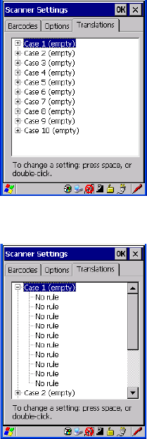
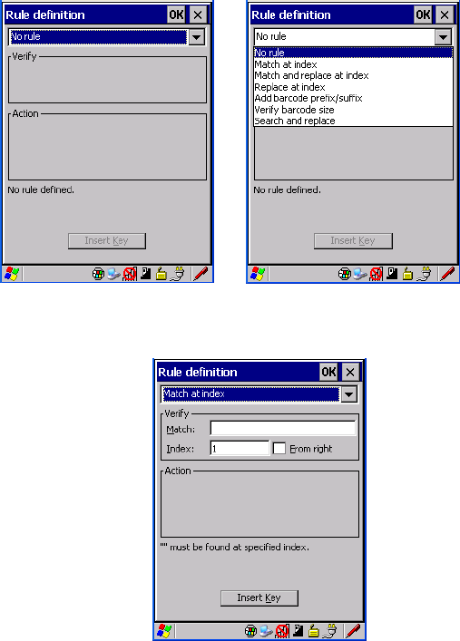
5.10.7 Translations Tab
The Translations tab allows you to define up to 10 cases, each consisting of up to 10
rules in sequential order. Only one case will be applied to a bar code and a case will
only be applied if all rules specified in the case are successful – if a rule within a
case fails, the entire case fails.
•In the Translation tab, tap on the Case # to create rules.
WORKABOUT PRO Hand-Held Computer With Windows CE 5.0 User Manual 203
Chapter 5: Configuration
Translations Tab
• Tap on the No rule dropdown menu to display the rules.
When you choose a rule, an associated screen is displayed in which you can define
the rule.
5.10.7.1 Case Rules
The case rules are defined as follows:
• No rule – ignored.
• Search and replace – replaces all instances of the match string. (Note that
this rule cannot fail.)
• Match at index – matches the match string at a specified index.

Chapter 5: Configuration
Translations Tab
204 WORKABOUT PRO Hand-Held Computer With Windows CE 5.0 User Manual
• Match and replace at index – matches the match string at a specified index
and replaces/changes it.
• Replace at index – replaces/changes unspecified data in a given range.
• Add barcode prefix/suffix – adds a global prefix or suffix.
• Verify barcode size – verifies the bar code size. This rule should generally
be assigned first, before creating subsequent rules.
Note: Keep in mind that the effects of previously applied rules must be taken
into account when creating subsequent rules. For example, if the bar code
size is important, it should be checked before any rules that might change
the size are applied.
Translation information about the status of each case/rule is displayed in the scan
log file (see “Scan Log File” on page 201) when enabled. This is useful if a case
fails, and you are trying to determine why a rule is failing.

WORKABOUT PRO Hand-Held Computer With Windows CE 5.0 User Manual 205
PERIPHERAL DEVICES & ACCESSORIES 6
6.1 Carrying Accessories.............................209
61 Protective Carrying Case........................212
6.2 The Batteries.................................213
6.3 Adaptor Cable Options............................213
6.4 Chargers And Docking Stations.......................213
6.4.1 Installation–Chargers And Docking Stations.............214
6.4.2 Power Consumption Considerations..................214
6.4.3 Operator Controls...........................214
6.4.4 Important Charger Safety Instructions.................214
6.5 Desktop Docking Station...........................216
6.5.1 Charging A Battery Installed In The WORKABOUT PRO. . . . . . 217
6.5.2 Charging A Spare Battery.......................218
6.5.3 Battery Charge Duration........................218
6.5.4 Charger LED Indicators........................218
6.5.5 Troubleshooting The Charging Operation Of The Dock .......218
6.5.6 Linking A WORKABOUT PRO To A PC ..............218
6.5.7 Linking A WORKABOUT PRO To An Ethernet Network . . . . . . 219
6.5.7.1 Network Access.........................219
6.5.8 Troubleshooting The Docking Station Operations. . .........219
6.8 Single Battery Charger–Model #WA3001-G1 . ...............221
6.8.1 Inserting A Battery In The Single Battery Charger..........222
6.8.2 Battery Charge Duration........................222
6.8.3 Charge Indicators–The LED......................222
Chapter 6: Peripheral Devices & Accessories
206 WORKABOUT PRO Hand-Held Computer With Windows CE 5.0 User Manual
6.9 Quad Battery Charger–Model #WA3004-G1.................223
6.9.1 Charging Batteries...........................223
6.9.2 Battery Charge Duration........................223
6.9.3 Charge Indicators–The LEDs......................223
6.9.4 Troubleshooting . . . .........................224
6.9.4.1 Excessive Charge Duration..................224
6.9.4.2 Indicator Flashing Red..................... 224
6.9.4.3 Power LED Does Not Light Up................224
6.9.4.4 Indicator Does Not Light When Battery Installed....... 224
6.10 Quad Docking Station–WA4204-G2 & WA4304-G2 ............225
6.10.1 Quad Docking Station Setup.....................225
6.10.2 Quad Indicators............................226
6.10.3 Inserting A WORKABOUT In The Quad Docking Station .....226
6.10.4 Network Access............................226
6.10.4.1 Network Addressing..................... 226
6.10.5 Battery Charging–LED Behaviour..................227
6.10.6 Troubleshooting . . . .........................227
6.10.6.1 Network Link Unsuccessful.................227
6.10.6.2 Hand-Held LED Does Not Light When Docked....... 227
6.12 Scanners And Imagers............................232
6.12.1 Scanning Techniques.........................232
6.12.2 Troubleshooting . . . .........................233
6.12.3 Operating One Dimensional (1D) Laser Scanners..........233
6.12.4 Operating Internal PDF Laser Scanners................234
WORKABOUT PRO Hand-Held Computer With Windows CE 5.0 User Manual 207
Chapter 6: Peripheral Devices & Accessories
6.12.5 Operating Two Dimensional (2D) Imagers..............234
6.13 Bluetooth Peripherals............................235

WORKABOUT PRO Hand-Held Computer With Windows CE 5.0 User Manual 213
Chapter 6: Peripheral Devices & Accessories
The Batteries
• Fasten the belt comfortably around your waist. Slide the adjustable ring on
the belt to tighten the holster in place.
• Connect the safety tether to one of the clips on the bottom of the soft shell
holster. Connect the other end to the hole in the end of the WORKABOUT
PRO pistol grip. This tether will catch the unit in case of a drop. The tether
can be adjusted to the operator’s height. The clips will break away in case
of a severe force.
6.2 The Batteries
The WORKABOUT PRO will operate with any of the following Lithium-Ion
battery packs:
• High-Capacity – Model WA3006
• Super High-Capacity – Model WA3010
In addition to the main battery, the hand-held is equipped with a replaceable,
rechargeable Lithium-Ion backup battery.
6.3 Adaptor Cable Options
The following are adaptors can be ordered for your WORKABOUT G2:
6.4 Chargers And Docking Stations
Important: Keep in mind when ordering a charger or docking station, you
must also order the appropriate power cord separately.
Psion Teklogix offers a variety of chargers and docking stations for the
WORKABOUT PRO. These include:
• AC Adaptor–Model No. PS1050-G1
Model Number Adaptor Cable Description
WA1002 Tether to USB device. This cable is used to connect USB
devices such as USB Flash memory devices.
WA4020-G2 Tether to RS232. This is a full RS232 port on COM2.
WA4001-G2 Tether to USB Client. (For ActiveSync)
WA4010-G1 USB to Ethernet adaptor.
WA4015 USB/RS232 adaptor. This cable is used with docking station
WA4003-G2.

Chapter 6: Peripheral Devices & Accessories
Installation–Chargers And Docking Stations
214 WORKABOUT PRO Hand-Held Computer With Windows CE 5.0 User Manual
• Cigarette Lighter Adaptor–Model No. WA3113-G2
• Single Battery Charger–Model No. WA3001-G1
• Quad Battery Charger–Model No. WA3004-G1
• Desktop Docking Station–Model No. WA4003-G2
• Quad Docking Station For 7527 C G2–Model No. WA4204-G2
• Quad Docking Station For 7527 S G2–Model No. WA4304-G2
6.4.1 Installation–Chargers And Docking Stations
When installing a charger or docking station, consider the following guidelines.
• Keep chargers and docking stations away from excessive dirt, dust and
contaminants.
• Chargers will not charge batteries outside an ambient temperature range
of 0° C to 45 °C (32° F to 113° F). It is recommended that the charger or
docking station be operated at room temperature–between 18° C and 25° C
(64° F to 77° F) for maximum performance.
After unpacking your unit:
• Visually inspect the charger for possible damage.
• Install the IEC power cord and apply power.
6.4.2 Power Consumption Considerations
Check to ensure the mains circuit supplying chargers and/or docking stations is
adequate for the load, especially if several chargers and docking stations are being
powered from the same circuit.
• Quad charger–can consume up to 2A @ 120VAC or 1A @ 240VAC.
• Quad docking station–can consume up to 3A @ 120VAC or 1.5A @
240VAC.
6.4.3 Operator Controls
WORKABOUT PRO docking stations and chargers have no operator controls or
power switches.
6.4.4 Important Charger Safety Instructions
•SAVE THESE INSTRUCTIONS–This manual contains important safety and
operating instructions for battery charger s.
WORKABOUT PRO Hand-Held Computer With Windows CE 5.0 User Manual 215
Chapter 6: Peripheral Devices & Accessories
Important Charger Safety Instructions
• Before using the battery charger, read all instructions and cautionary
markings on (1) battery charger, (2) battery, and (3) product using battery.
• The mains power cord shall comply with national safety regulations of the country
where the equipment is to be sold.
• Use of an attachment not recommended or sold by the battery charger
manufacturer may result in fire, electric shock, or personal injury.
• To reduce risk of damage to the electric plug and cord when unplugging the
charger, pull the plug rather than the cord.
• Make sure the cord is positioned so that it is not stepped on, tripped over,
or otherwise subjected to damage or stress.
• Do not operate the charger with a damaged cord or plug.
Replace immediately.
• Do not operate the charger if it has received a sharp blow, been dropped, or other-
wise damaged in any way; it should be inspected by qualified service personnel.
• Do not disassemble the charger; it should be repaired by qualified service person-
nel. Incorrect reassembly may result in electric shock or fire.
• To reduce risk of electric shock, unplug the charger from the outlet before
attempting any maintenance or cleaning.
• An extension cord should not be used unless absolutely necessary. Use of an
improper extension cord could result in fire or electric shock.
If an extension cord must be used, make sure:
• The plug pins on the extension cord are the same number, size,
and shape as those on the charger.
• The extension cord is properly wired and in good electrical
condition and that the wire size is larger than 16 AWG.
• Do not expose the charger to rain or snow.
• Do not place batteries in the charger if they are cold from extended
exposure to a freezer or outside temperatures below 10°C (50°F). Allow them to
warm up to room temperature for at least two hours.
• Do not use the charger if, after an overnight charge, any of the batteries feel warmer
than the charger housing. The charger should be inspected by
qualified service personnel.
• Do not use the charger if any of the batteries or the charger get more than luke-
warm. The equipment should be inspected by qualified personnel.

Chapter 6: Peripheral Devices & Accessories
Charging A Spare Battery
218 WORKABOUT PRO Hand-Held Computer With Windows CE 5.0 User Manual
6.5.2 Charging A Spare Battery
• Insert the battery in the spare battery charge well at the back of the docking
station, aligning the contacts on the battery with the contacts in the spare
battery charge well.
6.5.3 Battery Charge Duration
A fully discharged battery can take up to 5 hours to charge. The desktop docking
station stops applying power to the battery when it is fully charged–there is no risk
of overcharge if the battery remains in the charge well.
6.5.4 Charger LED Indicators
The desktop docking station is equipped with a single dual-coloured LED indicator
in the lower-right corner of the front panel.
Table 6.2 Desktop Battery Charger LED Behaviour
Note: Battery charging continues whether the hand-held is switched on or off.
6.5.5 Troubleshooting The Charging Operation Of The Dock
The quad battery charger troubleshooting section beginning on page 224 also
applies to the charging behaviour of the desktop docking station.
6.5.6 Linking A WORKABOUT PRO To A PC
The desktop docking station can be connected to a PC so that you can exchange files
in the same way that you would between PC drives. A USB cable is included with
your docking station.
Note: For information about data transfer with the Windows XP operating sys-
tem and ActiveSync and with the Vista operating system, refer to “Data
LED Behaviour Charge Status
Off No battery detected in the slot.
Solid Green Charge complete.
Fast Flashing Green Battery charged to less than 80% of capacity.
Slow Flashing Green Battery charged to greater than 80% of capacity.
Solid Red Battery temperature outside of charge range–
0° C to 50 °C.
Flashing Red Battery is not charging. Battery fault.
WORKABOUT PRO Hand-Held Computer With Windows CE 5.0 User Manual 219
Chapter 6: Peripheral Devices & Accessories
Linking A WORKABOUT PRO To An Ethernet Network
Transfer Between The PC & The Hand-Held” on page 20.
To link the WORKABOUT PRO to a PC:
• Insert the hand-held in the desktop docking station.
• Insert the USB cable into the docking station Client USB connector. Attach
the other end of the cable to a USB port on the PC.
6.5.7 Linking A WORKABOUT PRO To An Ethernet Network
An USB-Ethernet adaptor cable – model number WA4010-G1 – is used to connect
the WORKABOUT PRO to an Ethernet network through a desktop docking station.
• Insert the adaptor’s USB connector into the Host USB port on the desktop
docking station.
• Connect your network Ethernet cable to the Ethernet port on the adaptor
cable.
6.5.7.1 Network Access
The hand-held unit automatically detects insertion into the desktop dock and loads
the appropriate drivers to communicate with the USB-Ethernet converters.
Network Addressing
The host application uses standard TCP/IP protocol to name, locate and
communicate with a specific WORKABOUT PRO on the network.
If a link is established between a WORKABOUT PRO and a host, the application
on the host and on the hand-held must have a recovery mechanism in the event that
the WORKABOUT PRO is removed from the dock, interrupting the link.
6.5.8 Troubleshooting The Docking Station Operations
The indicators, applications and drivers required to use and monitor the desktop
docking station as a dock (as opposed to a charger) are installed on the
WORKABOUT PRO–no applications are present on the docking station itself.
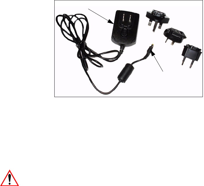
6.6 AC Wall Adaptor– Model #PS1050-G1
The AC wall adaptor available for your WORKABOUT PRO allows you to operate
your hand-held using AC power while charging the battery inserted in the unit.
Chapter 6: Peripheral Devices & Accessories
Cigarette Lighter Adaptor–Model #WA3113-G2
220 WORKABOUT PRO Hand-Held Computer With Windows CE 5.0 User Manual
Adaptor plugs suitable for use in the following countries are shipped with the AC
wall adaptor: United Kingdom, Australia, Europe and North America.
• Choose the adaptor plug that is suitable for use in your country. Slide the
adaptor plug into the Universal AC power supply, snapping it into place.
These two pieces, coupled together, are referred to as an AC wall adaptor.
• Insert the DC power plug into the DC IN socket at the base of WORK-
ABOUT PRO, located between the tether and LIF ports.
• Plug the pronged end into an AC outlet.
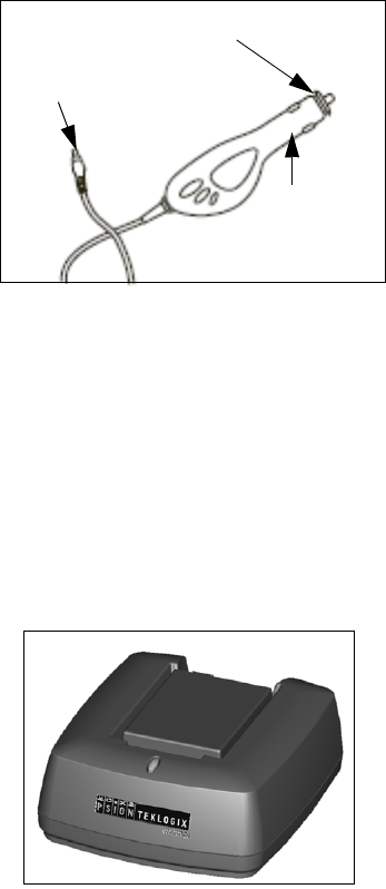
6.7 Cigarette Lighter Adaptor–Model #WA3113-G2
Important: It is critical that you review the safety instructions outlined in the
quick start guide enclosed with your cigarette lighter adaptor
before using the accessory.
Universal AC Power Supply
Adaptor Plugs
DC Power Plug
WORKABOUT PRO Hand-Held Computer With Windows CE 5.0 User Manual 221
Chapter 6: Peripheral Devices & Accessories
Single Battery Charger–Model #WA3001-G1
The cigarette lighter adaptor allows you to power your hand-held and recharge your
battery using power drawn from your vehicle’s cigarette lighter outlet.
Figure 6.4 Cigarette Lighter Adaptor
• Unscrew the adaptor end-cap, and remove the fuse inside the adaptor.
• Replace it with the fuse provided with your kit, and screw the adaptor end-
cap back into position.
• Insert the DC power plug into the DC IN socket at the base of the WORK-
ABOUT PRO.
• Insert the cigarette lighter adaptor plug into cigarette lighter outlet in your
vehicle.
6.8 Single Battery Charger–Model #WA3001-G1
The single battery charger is designed to charge a single battery. It has a DC IN
socket and is equipped with one LED that indicates the status of the charge process.
DC Power Plug
Cigarette Lighter
Adaptor Plug
Adaptor End-Cap

Chapter 6: Peripheral Devices & Accessories
Inserting A Battery In The Single Battery Charger
222 WORKABOUT PRO Hand-Held Computer With Windows CE 5.0 User Manual
6.8.1 Inserting A Battery In The Single Battery Charger
• Insert the DC power plug into the charger. Plug the pronged end of the
power cable into an AC outlet.
• Install the battery, aligning the contacts on the battery with the contacts in
the battery charge well.
6.8.2 Battery Charge Duration
It can take up to 4 hours to fully charge a battery. The single battery charger stops
applying power to the battery when it is fully charged–there is no risk of overcharge
if the battery remains in the charge well. The 75% charge indicator is handy if you
need a quick recharge–a quick charge often takes less than one hour.
6.8.3 Charge Indicators–The LED
The LED on the top of the charger indicates battery charge progress.
Table 6.3 Single Battery LED Behaviour
Note: Battery charging continues whether the hand-held is switched on or off.
LED Behaviour Charge Status
Off No battery detected in the charge well.
Solid green Battery is fully charged.
Fast flashing green Battery is charged to 75% of capacity.
Slow flashing green Charge in progress.
Solid red Battery is outside ambient temperature range of
0° C to 45 °C (32° F to 113° F).
Flashing red Charge alarm indicating a charging circuit problem. Refer to
“Troubleshooting” on page 224 for details.
Flashing red then green in a 3
second cycle Power up test sequence.
WORKABOUT PRO Hand-Held Computer With Windows CE 5.0 User Manual 223
Chapter 6: Peripheral Devices & Accessories
Quad Battery Charger–Model #WA3004-G1
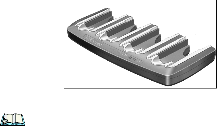
6.9 Quad Battery Charger–Model #WA3004-G1
The quad battery charger is designed to charge up to four Lithium Ion batteries at
one time.
Note: The gang charger is shipped with a user manual. It is critical that this
manual be reviewed for additional information and updates.
6.9.1 Charging Batteries
• Slide the battery into a charge well, aligning the contacts on the battery with
the contacts in the charge well.
6.9.2 Battery Charge Duration
A fully discharged battery can take up to 4 hours to charge. The quad battery charger
stops applying power to the battery when it is fully charged–there is no risk of
overcharge if the battery remains in the charge well. The 75% charge indicator is
handy if you need a quick recharge–a quick charge often takes less than one hour.
6.9.3 Charge Indicators–The LEDs
Each battery charge well is equipped with an LED to indicate the charge status of
the battery. When a battery is inserted in the charger, the colour and behaviour of the
LED associated with the charge well in use indicates the status of the charge. Refer
to Table 6.3 on page 222 for details.
Chapter 6: Peripheral Devices & Accessories
Troubleshooting
224 WORKABOUT PRO Hand-Held Computer With Windows CE 5.0 User Manual
6.9.4 Troubleshooting
6.9.4.1 Excessive Charge Duration
The charger is equipped with a recalibration function–a function that fully
discharges and then fully recharges the battery. This process is necessary to
recalibrate the battery capacity gauge internal to the battery. The charger attempts
recalibration when:
• the battery capacity is at less than 30%, and
• the battery has undergone more than 40 partial charge cycles since the last
full discharge.
The recalibration function extends the charge time by up to 2 hours.
6.9.4.2 Indicator Flashing Red
If the indicator flashes red:
• Remove all batteries and disconnect the mains power cable.
• Wait at least 20 seconds, and then plug the cable in again.
If any of the charge well LEDs continue to flash red, the charger is defective and
requires service. If all indicators are flashing red, there is a power supply problem
and the charger requires service.
6.9.4.3 Power LED Does Not Light Up
• Remove all batteries, and unplug the charger.
• Connect another device to the mains outlet to ensure there is power.
• Remove the IEC mains power cable from the charger, and check it for damage.
• Reconnect the mains cable in the charger and mains outlet.
If the power LED still does not light up:
• Unplug the mains cable, and check the fuse at the rear of the charger.
If the fuse appears to be intact, the charger requires service.
6.9.4.4 Indicator Does Not Light When Battery Installed
• Remove the battery, and clean the contacts on the battery and the
charge well.
• Reinstall the battery, and check that it is fully seated in the charger well.
• Inspect the charge well contacts for damage (are they bent, flattened,
twisted or broken).
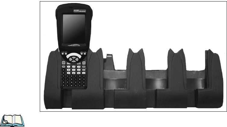
WORKABOUT PRO Hand-Held Computer With Windows CE 5.0 User Manual 225
Chapter 6: Peripheral Devices & Accessories
Quad Docking Station–WA4204-G2 & WA4304-G2
• Try inserting a battery that you know to be working in the charger well.
• Reconnect the mains power cable, and check that the charger well indicator
flashes at powerup.
6.10 Quad Docking Station–WA4204-G2 & WA4304-G2
Note: WA4204-G2 is designed for WORKABOUT PRO C models; WA4304-G2
is designed for WORKABOUT PRO S models.
The quad docking station is shipped with a docking manual. It is critical
that this manual be reviewed for additional information and updates.
The quad docking station permits each of four docked WORKABOUT PROs to
communicate with a 10/100 BaseT Ethernet network at greater than 2Mbps. It also
provides sufficient power to operate and fast charge the batteries in the units.
6.10.1 Quad Docking Station Setup
After unpacking the unit:
• Visually inspect the unit for any damage.
• Install the IEC power cord and apply power.
A green indicator in the lower-right corner of the front panel lights up to indicate
that power is present.
• Attach a CAT5 RJ45 network patch cable (supplied) between your network
and the RJ45 jack on the rear of the dock.

Chapter 6: Peripheral Devices & Accessories
Quad Indicators
226 WORKABOUT PRO Hand-Held Computer With Windows CE 5.0 User Manual
A green LED is illuminated next to the RJ45 connector when a valid network link is
established.
A user application must be loaded onto each WORKABOUT PRO that utilizes the
quad dock for communication. When the network is connected and this application
is loaded, the quad dock is ready for use.
6.10.2 Quad Indicators
The quad dock is equipped with a power indicator LED and RJ45 link and traffic
indicator LEDs. When a valid network link is established, a green LED is
illuminated next to the RJ45 connector.
6.10.3 Inserting A WORKABOUT In The Quad Docking Station
• Slide the WORKABOUT PRO into the cradle portion of the quad dock
until lightly latched.
The hand-held detects that it is in a quad dock and momentarily displays the appropriate
icon in the navigation bar at the top of the screen–. The LED on the hand-held unit
lights up to show it has external power and may start charging the battery.
Interaction with the WORKABOUT PRO while in the quad dock is a function of
the user application software used to communicate with the host network.
6.10.4 Network Access
The quad docking station has one 10/100 Ethernet port. You can insert up to four
hand-held units. The hand-helds are connected to an internal USB hub. The hand-
held unit automatically detects insertion into a quad docking station and loads the
appropriate drivers to communicate with the USB/Ethernet converters.
6.10.4.1 Network Addressing
Although the USB converters have fixed Ethernet MAC addresses, there is
generally no correlation between these addresses and a specific hand-held. The host
application uses standard TCP/IP protocol to name, locate and communicate with a
specific WORKABOUT PRO on the network.
If a link is established between a WORKABOUT PRO and a host, the application
on the host and on the hand-held must have a recovery mechanism in the event that
the WORKABOUT PRO is removed from the dock and the link is interrupted.
WORKABOUT PRO Hand-Held Computer With Windows CE 5.0 User Manual 227
Chapter 6: Peripheral Devices & Accessories
Battery Charging–LED Behaviour
6.10.5 Battery Charging–LED Behaviour
The quad docking station supplies DC power to enable the WORKABOUT PRO
internal fast charger. Charge status is displayed on the hand-held LED–the LED
turns red while the battery is being charged and turns green once the charge is
complete. If the battery is fully charged when the unit is inserted in the docking
station, the LED flashes red for less than a second and then turns green. Battery
charging continues whether the WORKABOUT PRO is switched on or off.
It can take up to 4 hours to fully charge the internal battery.
6.10.6 Troubleshooting
The indicators, applications and drivers required to use and monitor the docking
station are installed on the WORKABOUT PRO–no indicators or applications are
present on the docking station itself.
6.10.6.1 Network Link Unsuccessful
If a network link fails, the WORKABOUT PRO application alerts the operator that
the link was unsuccessful.
6.10.6.2 Hand-Held LED Does Not Light When Docked
• Check that the quad docking station has power–is the Power LED on the
docking station illuminated?
• Try inserting the WORKABOUT PRO in another well in the quad dock.
• Check for dirt or contamination on the docking contacts at the bottom of the
WORKABOUT PRO. Wipe the contacts with a damp cloth if necessary.
• Check the pogo pins inside the dock cradle for dirt. Gently wipe with a
damp cloth if they appear to be dirty or discoloured.
• Check that the pogo pins are not bent or damaged.
• Remove and reinsert the WORKABOUT PRO in the cradle, and check that
the latch is holding the unit in place (the pogo pins must be compressed for
proper contact).
• Make certain that the battery installed in the WORKABOUT PRO is not
defective.

Chapter 6: Peripheral Devices & Accessories
Operating Internal PDF Laser Scanners
234 WORKABOUT PRO Hand-Held Computer With Windows CE 5.0 User Manual
Important: If an aiming dot is available on the installed scanner, the dot will
be enabled for a configurable time period (including off), after
which normal scanning begins. Refer to “Dot Time (msec)” on
page 137 for details.
Double-clicking the trigger will override the aiming delay and
initiate an immediate scan. Note that the aiming dot is standard
on long-range and high visibility internal scanners.
• Aim at the bar code and press the scan key or the trigger. A scan beam and a
warning indicator appear until a successful decode is achieved or six
seconds have elapsed.
6.12.4 Operating Internal PDF Laser Scanners
This scanner decodes PDF417 two-dimensional bar codes.
• Turn the hand-held on. Wait until the unit has booted up completely.
• Aim at the bar code and press the scan key or the trigger. The beam expands
into a rectangle covering the bar code to properly scan it. The scan beam
and a warning indicator are visible until a successful decode is achieved or
three seconds have elapsed.
6.12.5 Operating Two Dimensional (2D) Imagers
An imager takes a snap shot of a single bar code or multiple bar codes (at one time).
It can find a bar code regardless of its orientation—that is, even a bar code printed at
a 45 degree angle to the hand-held will be decoded successfully.
Note: When scanning multiple bar codes, ensure that all of the desired bar
codes are within the field of view of the scanner. It is possible that even
when all bar codes are within the field of view, not all of them will be
decoded. Only successfully decoded bar codes are passed to the applica-
tion program. The application program then issues a warning, asking that
you scan the missing bar codes.
When scanning a single bar code, ensure that only the desired bar code is
within the field of view of the scanner.

WORKABOUT PRO Hand-Held Computer With Windows CE 5.0 User Manual 235
Chapter 6: Peripheral Devices & Accessories
Bluetooth Peripherals
Because imagers generally have a shorter depth of field than laser scanners, some
practise may be required to find the optimal distance from the types of bar codes
being scanned. Although the imager includes illumination LEDs, ambient light will
help the imager decode the bar codes, especially if the bar code is far from the hand-
held.
Important: Keep in mind that the imager scanner is a camera, and the LED
illumination is a flash. Glare can be an issue on reflective media
such as plastic coated bar codes, just as glare is an issue for photog-
raphers. When pointing at a shiny surface, either shift the bar code
to the side or top, or angle the bar code so that the glare reflects
away from the imager scanner.
Most imagers take several ‘snap shots’ of the bar code in order to
decode it. It is normal for the LEDs to flash two or three times. Hold
the unit steady between flashes to improve decode performance.
• Turn the hand-held computer on. Wait until the unit has booted
up completely.
• Aim at the bar code and press the scan key or the trigger. Hold the trigger
until a successful or failed scan result is obtained.
• When the scan button or trigger is pressed, a red, oval shaped light (the
framing marker) is displayed. Centre the framing marker in the field—
either in the centre of the bar code you want to scan or in the centre of the
area in which multiple bar codes are to be scanned.
The illumination LEDs will flash (typically several times) and a picture of the bar
code(s) is taken.
6.13 Bluetooth Peripherals
The WORKABOUT PRO is equipped with a Bluetooth radio, making it is possible
to communicate with a variety of Bluetooth peripherals, including GSM/GPRS
handsets, scanners, printers, and so on.
The range of the Bluetooth radio is limited to approximately 5 meters.
Psion Teklogix provides built-in support for the Bluetooth peripherals listed below.
• GSM/GPRS universal handset
•Bluetooth printer
•Bluetooth headset
Chapter 6: Peripheral Devices & Accessories
Bluetooth Peripherals
236 WORKABOUT PRO Hand-Held Computer With Windows CE 5.0 User Manual
Keep in mind that Bluetooth and IEEE 802.11b/g radios both operate in the 2.4GHz
band. Although the WORKABOUT PRO includes features to minimize
interference, performance of the system will not be optimal if you use both radios
simultaneously. Typically, when both radios operate in the hand-held at the same
time, they cannot transmit simultaneously–this has a negative impact on overall
system throughput. To minimize the impact on the backbone 802.11g network,
Psion Teklogix recommends using Bluetooth peripherals that have low transaction
rates (such as printers and scanners).
Refer to “Bluetooth Setup” on page 109 for information about setting up your Blue-
tooth devices for communication. In addition, review the manual shipped with your
Bluetooth device to determine the method used to pair with the WORKABOUT
PRO host.

WORKABOUT PRO Hand-Held Computer With Windows CE 5.0 User Manual 237
SPECIFICATIONS 7
7.1 WORKABOUT PRO Specifications.....................239
7.2 Radio Specifications.............................244
7.3 Battery Specifications ............................246
7.3.1 High-Capacity (Model WA3006) . . . . . . . . . . . . . . . . . . .246
7.3.1.1 Electrical Specifications...................246
7.3.1.2 Standard Discharge .....................247
7.3.1.3 Safety Data..........................248
7.3.1.4 Safety License........................249
7.3.1.5 Environmental Test .....................249
7.3.2 Super High-Capacity (Model WA3010) . . . . . . . . . . . . . . .250
7.3.2.1 Electrical Specifications...................250
7.3.2.2 Standard Discharge .....................251
7.3.2.3 Safety Data..........................252
7.3.2.4 Safety License........................252
7.3.2.5 Environmental Test .....................253
7.4 Scanner Model Numbers...........................254
7.5 Scanner Specifications............................254
7.5.1 SE 1223HP, LR, ALR And SE 955HP Specifications . . . . . . . .254
7.5.1.1 SE 1223HP Decode Zone..................256
7.5.1.2 SE 1223LR Decode Zone..................256
7.5.1.3 SE 1223ALR Decode Zone . . . . . . . . . . . . . . . . .256
7.5.1.4 SE 955HP Decode Zone...................257
7.5.2 EV15 Imager Specifications.....................257
7.5.2.1 EV15 Imager Decode Zone . . . . . . . . . . . . . . . . .258
7.5.3 HHP5180 Imager...........................258
7.5.3.1 HHP5180 Imager Decode Zone . . . . . . . . . . . . . . .259
7.5.4 SX5393 Imager . . . . . . . . . . . . . . . . . . . . . . . . . . . .260
7.5.4.1 SX5393 Imager Decode Zone . . . . . . . . . . . . . . . .261

WORKABOUT PRO Hand-Held Computer With Windows CE 5.0 User Manual 239
Chapter 7: Specifications
WORKABOUT PRO Specifications
Note: Performance specifications are nominal & subject to change without
notice.
7.1 WORKABOUT PRO Specifications
Model Variants
• WORKABOUT PRO C – Model 7527C-G2
• WORKABOUT PRO S – Model 7527S-G2
Platform
• PXA270 @ 520 MHz, 32 bit RISC CPU
• 128 MB flash, 128 MB RAM
Operating System
• Microsoft® Windows® CE 5.0
Wireless Communication
Optional expansion modules for:
• 802.11b/g (via Compact Flash) operating in the 2.4GHz band:
- Supports IEEE 802.11b data rates of 1,2,5.5 and 11Mbps using Direct
Sequence Spread Spectrum (DSSS).
- Supports IEEE 802.11g data rates of 6,9,12,24,36,48 and
54Mbps,using Orthagonal Frequency Division Multiplexing (OFDM)
base band modulation

Chapter 7: Specifications
WORKABOUT PRO Specifications
240 WORKABOUT PRO Hand-Held Computer With Windows CE 5.0 User Manual
Bar Code Applications
• Optional 1D imager expansion module
• Optional 2D imager expansion module
• Optional 1D SE955 laser scanner expansion module
• Optional 1D SE1223 High Performance laser scanner expansion module
• Optional bolt-on pistol grip
Note: All are user upgradeable
RFID Modules
• UHF module
- Frequency: 902 MHz or 928 MHz
- Read range: up to 4.92 ft.(150 cm) [915MHz] and up to 2.62 ft.(80 cm)
[868 MHz]
- Tag supported: EPC Class 1 Gen 2, other protocols depending on
regions
User Interface
• Color Touch Screen Display 3.6 in.(9.144 cm) diagonal
- Full VGA 480x640 resolution
- Transflective, portrait mode TFT
- Adjustable Backlight
WORKABOUT PRO Hand-Held Computer With Windows CE 5.0 User Manual 241
Chapter 7: Specifications
WORKABOUT PRO Specifications
- Sunlight readable (for outdoor use)
- High reliability LED backlight
- Easily replaceable and customizable bezel
• Touchscreen
- Passive stylus or finger operation
- Signature capture
• Keyboards
- Full Alpha-Numeric (C model)
- Numeric (S model)
- Ergonomically enhanced for ambidextrous, one-hand operation
- Backlit, high durability hard-capped keys
• Indicators And Controls
- LED indicates battery charge status
Programming Environment
• Psion Teklogix Mobile Devices SDK
• Hardware Development Kit (HDK)
• .NET and C++ programming using Microsoft® Visual Studio® 2005
• Java programming supporting JDK 1.2.2 or higher
• Standard Protocol APIs
- Windows sockets (CE .net)
Application Software
• Internet Explorer 6.0 incl.with Windows CE 5.0
• Unique Psion Teklogix Voice Dialer and Contacts Manager incl.Windows
CE 5.0
• PTX Connect VoIP
• Optional Open TekTerm terminal emulation software, supports IBM
5250,IBM 3270, HP2392, ANSI and TESS
• Mobile Control Center (MCC) device management
Chapter 7: Specifications
WORKABOUT PRO Specifications
242 WORKABOUT PRO Hand-Held Computer With Windows CE 5.0 User Manual
Expansion Slots
• One SD/MMC memory card slot – user accessible
• End-cap USB Interface supports GPS expansion module
• 100-PIN expansion interface: supports PCMCIA (type II),GSM/GPRS
EDGE and other third-party expansion modules developed using Psion
Teklogix WORKABOUT PRO Hardware Developer’s Kit
• Flex cable interface with robust connector: supports scanner (serial) and
imager (USB) modules
• One Type II CF Card Slot
External Connectors
• One Tether connection with full RS232 and USB 1.1 functionality
• One Low-Insertion Force (LIF) docking connector
• DC Power Jack
Power Management
• Optional 3.7V, 3000 mAh High Capacity Battery Pack
• Optional 3.7V, 4000 mAh Super High Capacity Battery Pack
• Advanced Smart Battery with gas gauge
• 3 power source options: Runs off battery, AC power, or automotive power
supplies
• Built-in charger
• Rechargeable, user replaceable backup battery pack
Environmental
• Withstands 26 drops (on 12 edges,8 corners, 6 faces) at 5 ft.(1.5 meters) to
polished concrete while powered on and configured with accessories such
as CF radio, scanner/imager, and pistol grip
• Rain/Dust: IP65,IEC 60529
• Operating Temperature: 14°F to 122°F (-10°C to +50°C)
• 5%-95% RH non-condensing
• Storage Temperature: -40°F to 140°F (-40°C to +60°C)
WORKABOUT PRO Hand-Held Computer With Windows CE 5.0 User Manual 243
Chapter 7: Specifications
WORKABOUT PRO Specifications
Physical Dimensions And Weight
• WORKABOUT PRO C:
- 8.775 in. x 2.95/3.94 in. x 1.22/1.65 in. (223 mm x 75/100 mm x 31/42
mm)
• WORKABOUT PRO S:
- 7.87 in. x 2.95/3.94 in. x 1.22/1.65 in. (200 mm x 75/100 mm x 31/42
mm)
• Weight (w/o battery pack):
- WORKABOUT PRO C:1 lbs (455 g)
- WORKABOUT PRO S:.859 lbs (390 g)
Power Accessories
• AC power supply (charge & operate hand-held)
• Automotive power supply (charge & operate hand-held)
• Single and Quad slot battery pack chargers
• Powered cradle for vehicle mount applications
Communication Accessories
• Quad Dock (4-site) with 10/100 BaseT Ethernet and charge functions
• Desktop Docking Station (charges hand-held & spare battery) provides
USB1.1 host and device ports and supports optional plug-on expansion
modules supporting 10/100 BaseT Ethernet or RS232 connections
• USB cable supports Active Sync without requiring a docking station
• Optional End-Caps supporting RS232, TTL, and IrDA
Carrying Accessories
• Hand-strap, pistol grip with trigger, holster and various protective carrying
cases and pouches
Approvals
• Safety:
- CSA/UL60950-1, IEC 60950-1, EN60950-1
•EMC:
- FCC Part 15 Class B
- EN 55022
- EN 55024

Chapter 7: Specifications
Battery Specifications
246 WORKABOUT PRO Hand-Held Computer With Windows CE 5.0 User Manual
-
Bluetooth
Radio
Embedded (920 kbps serial interface)
Bluetooth Version 1.2 compliant (features Adaptive Frequency
Hopping for better co-existence with 802.11 radio)
Chip Antenna 2dBi peak
Transmit Power -3dBm (0.5mW) minimum, +4dBm (2.5mW) max
Frequency Range 2.400 - 2.4835 GHz
RX Sensitivity -80dBm max
(BER<=0.1%)
Data Rate 732.2 kbps and 57.6 kbps asymmetric,
433.9 kbps symmetric
7.3 Battery Specifications
7.3.1 High-Capacity (Model WA3006)
7.3.1.1 Electrical Specifications
Note: The electrical specifications apply for ambient temperature TAMB of 0° to
+40°C unless otherwise stated.
Item Description Specification Remark
1 Interface Chipset Maxim DS2762 -
2 Rated Voltage 3.7V Typical
3 Rated Capacity 3000mAh Typical
4 Rated Charge Current 1.5A Maximum
5 Charge Voltage 4.2 +/- 0.05V Maximum
6 Discharge Cut-off voltage 2.6V Typical
7 Discharge Current Constant voltage
Current limited -
8 Discharge Current 0.5C (-20°C to 60°C) Typical
9 Internal Resistance 200 m Maximum
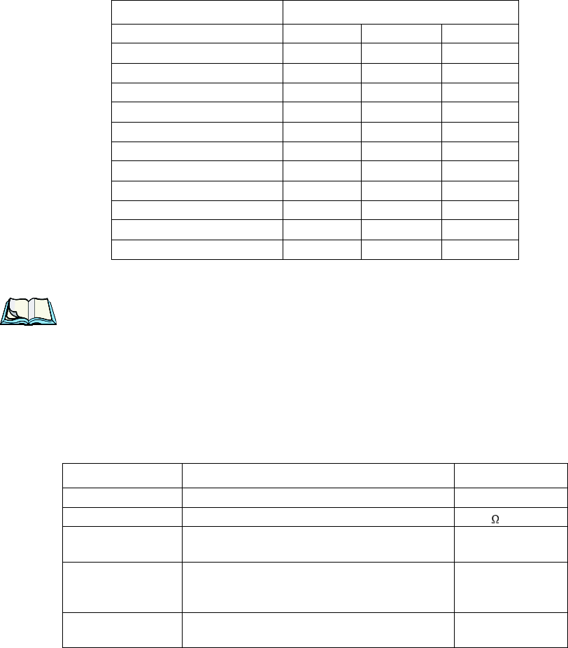
WORKABOUT PRO Hand-Held Computer With Windows CE 5.0 User Manual 247
Chapter 7: Specifications
Standard Discharge
Battery Pack Electrical Specifications
7.3.1.2 Standard Discharge
Note: Standard charge is defined as charging with constant voltage limit of 4.2V
and constant current limit of 0.9A; the termination charge occurs when
the current drops to 45mA.
Standard discharge is defined as discharging at a constant current of
350mA until the battery protection circuit switches the battery output off in
over-discharge mode.
Acceptance Test Specifications
Description Specification
Minimum Typical Maximum
Over voltage detection voltage 4.325V 4.350V 4.375V
Charge enable 4.10V 4.15V 4.20V
Under voltage detection voltage 2.5V 2.6V 2.7V
Over current detection current - 3.5A -
Short-circuit detection current 5.0A 8.0A 11.0A
Short-circuit detection voltage 150mV 200mV 250mV
Over voltage delay time 0.8s 1s 1.2s
Under voltage delay time 90ms 100ms 110ms
Over current delay time 5ms 10ms 20ms
Short-circuit delay time 160µs 200µs 240µs
Recovery charge current 0.5mA 1mA 2mA
Description Condition Standard
Open circuit voltage After standard charge, measure within 24 hours. 4.15V or more
Internal Resistance After standard charge, measure within 24 hours. 200 m max.
Capacity_1 After standard charge, measure time taken for a fast
discharge. 110 minutes or more
Charge/Discharge
Cycle
After repeating standard charge and fast discharge,
measure the fast discharge time after 300 discharge
cycles.
90 minutes or more
Capacity_2 After standard charge, measure the time taken for a
standard discharge. 500 minutes or more

Chapter 7: Specifications
Safety Data
248 WORKABOUT PRO Hand-Held Computer With Windows CE 5.0 User Manual
7.3.1.3 Safety Data
Over Discharge
After standard charge, apply a standard discharge
followed by a standby discharge. Then measure
capacity after carrying out standard charge and then a
fast discharge.
110 minutes or more
Self discharge After a standard charge, keep battery at 25°C for 30
days. Measure the time taken for a fast discharge. 100 mins or more
Temperature
Perform a standard charge and fast discharge at 0°C,
25°C and 40°C and measured the time taken for a
fast discharge at 25°C.
100 mins. @ 0°C
110 mins. @ 23°C
105 mins. @ 40°C
Temp./Humidity
Cycle
After standard charge, carry out 5 cycles of the fol-
lowing: 65°C and 90% humidity for 8 hrs.
25°C and 65% humidity for 4 hrs.
-20°C for 8 hrs. 25°C and 65% humidity for 4 hrs.
Following that, perform a fast discharge, standard
charge and then a fast discharge. Measure the time
taken for the second discharge.
100 minutes or more
Dry heat
After standard charge, keep the battery at 60°C for 8
hrs. Carry out a fast discharge, standard charge and
then a fast discharge, measured the time taken for the
second discharge.
100 minutes or more
EMC/CE Testing
The battery will need to pass the requirements of the
EMC directive 89/336/EEC (and amendments) when
fitted into the product:
Emissions to EN55022 Class B (1998) Immunity to
EN55024 (1998)
Test to be performed
by manufacturer.
Electro-Static Dis-
charge Test
EN61000-4-8:
A. Contact Discharge: +/-8kV for each contact pad
by 10 times.
B. Air Discharge: +/-15kV for 10 times (the dis-
charge test point is for around battery casing.)
No damage
Description Condition Test Condition/Result
Short Circuit Test After a standard charge, short
terminals and discharge for 1 hr.
Protection circuit board to operate.
No explosion, fire, smoke, or leakage.
Over Charging Test
After a standard charge, charge
continuously at 4.2V and 4A for
8 hrs.
Protection circuit board to operate.
No explosion, fire, smoke, or leakage.
Description Condition Standard

WORKABOUT PRO Hand-Held Computer With Windows CE 5.0 User Manual 249
Chapter 7: Specifications
Safety License
7.3.1.4 Safety License
7.3.1.5 Environmental Test
Reverse Charging Test
After a standard discharge,
reverse-charge continuously at
4.2V and 4A for 8hrs.
Protection circuit board to operate.
No explosion, fire, smoke, or leakage.
Item License Standard
1 UL 1642 The lithium-ion cell has been listed and pass the UL1642 stan-
dard by UL Lab.
2 UL 2054 The battery pack is in the process to apply the UL 2054 battery
standard.
389/336 EEC-EMC
directive.
The battery pack is in the process to apply the below standard:
-EN55022 -LVD 72/23 EEC -EN55024 -EN61326
4 RoHS Directive The battery pack is in the process to apply the RoHS directive
applicable report by SGS Lab.
Description Test Reference Test Condition/Result
Drop (mechanical)
Drop sample battery on all faces from height of
1.2 meters onto concrete floor.
No explosion, fire, vent, leakage and the open
circuit voltage higher than 3.7V.
Storage at high temp. EN60068-2-2 Test +60°C dry for 240 hours
No explosion, fire, vent or leakage.
Storage at low temp. EN60068-2-1 Test -20°C dry for 240 hours
No explosion, fire, vent or leakage.
Storage at high temp.
and high humidity IEC68-2-3 Test +40°C at 90%RH for 240 hours.
No explosion, fire, vent or leakage.
Storage temp. cycling IEC68-2-14 Test
+60oC (2C) for 1 hour (T1), -20oC (2C) for 1
hour. 3 minutes Max allowed for change
between T1 and T2.
Cycle 10 times
No explosion, no fire, no vent, and no leakage.
Vibration resistance BS2011 Part 2.1
FDC (IEC68-2-37)
After standard charge, tested under the following
conditions: Random vibration 5Hz-500Hz ASD
0.02g2/Hz in 3 axis for 15 mins. After which,
carry out a standard discharge, charge, discharge.
No parting joints/cracks or damage to connec-
tors. No leakage or critical damage.
Description Condition Test Condition/Result
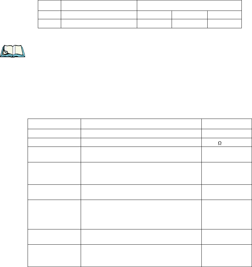
WORKABOUT PRO Hand-Held Computer With Windows CE 5.0 User Manual 251
Chapter 7: Specifications
Standard Discharge
7.3.2.2 Standard Discharge
Note: Standard charge is defined as charging with constant voltage limit of 4.2V
and constant current limit of 0.9A; the termination charge occurs when
the current drops to 45mA.
Standard discharge is defined as discharging at a constant current of
350mA until the battery protection circuit switches the battery output off in
over-discharge mode.
Acceptance Test Specifications
10 Short-circuit delay time 160µs 200µs 240µs
11 Recovery charge current 0.5mA 1mA 2mA
Description Condition Standard
Open circuit voltage After standard charge, measure within 24 hours. 4.15V or more
Internal Resistance After standard charge, measure within 24 hours. 150 m max.
Capacity_1 After standard charge, measure time taken for a fast
discharge. 110 minutes or more
Charge/Discharge
Cycle
After repeating standard charge and fast discharge,
measure the fast discharge time after 300 discharge
cycles.
90 minutes or more
Capacity_2 After standard charge, measure the time taken for a
standard discharge. 500 minutes or more
Over Discharge
After standard charge, apply a standard discharge
followed by a standby discharge. Then measure
capacity after carrying out standard charge and then a
fast discharge.
110 minutes or more
Self discharge After a standard charge, keep battery at 25°C for 30
days. Measure the time taken for a fast discharge. 100 mins or more
Temperature
Perform a standard charge and fast discharge at 0°C,
25°C and 40°C and measured the time taken for a
fast discharge at 25°C.
100 mins. @ 0°C
110 mins. @ 23°C
105 mins. @ 40°C
Item Description Specification

Chapter 7: Specifications
Safety Data
252 WORKABOUT PRO Hand-Held Computer With Windows CE 5.0 User Manual
7.3.2.3 Safety Data
7.3.2.4 Safety License
Temp./Humidity
Cycle
After standard charge, carry out 5 cycles of the fol-
lowing: 65°C and 90% humidity for 8 hrs.
25°C and 65% humidity for 4 hrs.
-20°C for 8 hrs. 25°C and 65% humidity for 4 hrs.
Following that, perform a fast discharge, standard
charge and then a fast discharge. Measure the time
taken for the second discharge.
100 minutes or more
Dry heat
After standard charge, keep the battery at 60°C for 8
hrs. Carry out a fast discharge, standard charge and
then a fast discharge. Measure the time taken for the
second discharge.
100 minutes or more
EMC/CE Testing
The battery will need to pass the requirements of the
EMC directive 89/336/EEC (and amendments) when
fitted into the product:
Emissions to EN55022 Class B (1998) Immunity to
EN55024 (1998)
Test to be performed
by manufacturer.
Electro-Static Dis-
charge Test
EN61000-4-8:
A. Contact Discharge: +/-8kV for each contact pad
by 10 times.
B. Air Discharge: +/-15kV for 10 times (the dis-
charge test point is for around battery casing.)
No damage
Description Condition Test Condition/Result
Short Circuit Test After a standard charge, short
terminals and discharge for 1 hr.
Protection circuit board to operate.
No explosion, fire, smoke, or leakage.
Over Charging Test
After a standard charge, charge
continuously at 4.2V and 4A for
8 hrs.
Protection circuit board to operate.
No explosion, fire, smoke, or leakage.
Reverse Charging Test
After a standard discharge,
reverse-charge continuously at
4.2V and 4A for 8hrs.
Protection circuit board to operate.
No explosion, fire, smoke, or leakage.
Item License Standard
1 UL 1642 The lithium-ion cell has been listed and pass the UL1642 stan-
dard by UL Lab. File No. MH12383
Description Condition Standard

WORKABOUT PRO Hand-Held Computer With Windows CE 5.0 User Manual 253
Chapter 7: Specifications
Environmental Test
7.3.2.5 Environmental Test
2 UL 2054 The battery pack is in the process to apply the UL 2054 battery
standard. File No. MH29921.
389/336 EEC-EMC
directive
The battery pack is in the process to apply the below standard:
-EN55022 -LVD 72/23 EEC -EN55024 -EN61326
4 RoHS Directive The materials of battery pack are used in accordance with the
European RoHS directive.
Description Test Reference Test Condition/Result
Drop (mechanical)
Drop sample battery on all faces from height of
1.2 meters onto concrete floor.
No explosion, fire, vent, leakage and the open
circuit voltage higher than 3.7V.
Storage at high temp. EN60068-2-2 Test +60°C dry for 240 hours
No explosion, fire, vent or leakage.
Storage at low temp. EN60068-2-1 Test -20°C dry for 240 hours
No explosion, fire, vent or leakage.
Storage at high temp.
and high humidity IEC68-2-3 Test +40°C at 90%RH for 240 hours.
No explosion, fire, vent or leakage.
Storage temp. cycling IEC68-2-14 Test
+60°C (2C) for 1 hour (T1), -20oC (2C) for 1
hour. 3 minutes Max allowed for change
between T1 and T2.
Cycle 10 times
No explosion, no fire, no vent, and no leakage.
Vibration resistance BS2011 Part 2.1
FDC (IEC68-2-37)
After standard charge, tested under the following
conditions: Random vibration 5Hz-500Hz ASD
0.02g2/Hz in 3 axis for 15 mins. After which,
carry out a standard discharge, charge, discharge.
No parting joints/cracks or damage to connec-
tors. No leakage or critical damage.
Impact shock resis-
tance -3 cycles of 50G 11ms, 1/2 sine pulse acceleration
applied in 6 directions. 18 shocks total.
ESD protection - Accordance with EN61000-4-8
Item License Standard

WORKABOUT PRO Hand-Held Computer With Windows CE 5.0 User Manual A-1
APPENDIX A
PORT PINOUTS
A.1 LIF (Low Insertion Force) Port Pinout
A.2 Tether Port Pinout
PIN # Signal Name
1 Ground
2 Ground
3 USB Host Data Plus, For connecting USB devices
4 USB Host Data Minus, For connecting USB Devices
5 USB Host Power, for powering USB devices (5V, 100mA Max)
6 DC Power in, for supplying power to WORKABOUT PRO / charging
battery (5V, 3A)
7 DC Power in, for supplying power to WORKABOUT PRO / charging
battery (5V, 3A)
8 LIF Detect, determines if a device is attached to the LIF
9 USB Device Data Minus, for operating the WORKABOUT PRO as a
USB device
10 USB Device Data Plus, for operating the WORKABOUT PRO as a
USB device
11 Ground
12 Ground
PIN # Signal Name
1Ground
2 USB Data Plus (can be configured as Host or Device)
3 USB Data Minus (can be configured as Host or Device)
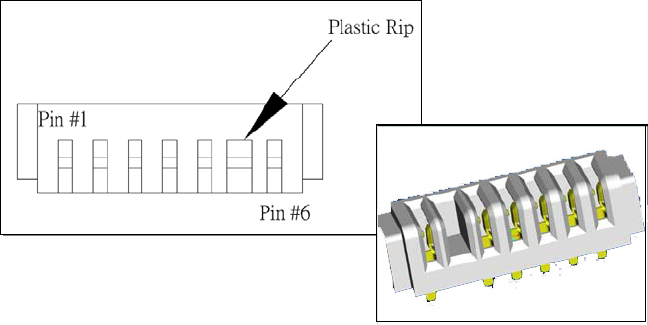
WORKABOUT PRO Hand-Held Computer With Windows CE 5.0 User Manual A-3
Appendix A: Port Pinouts
Positive Female Battery Connector
A.4 Positive Female Battery Connector
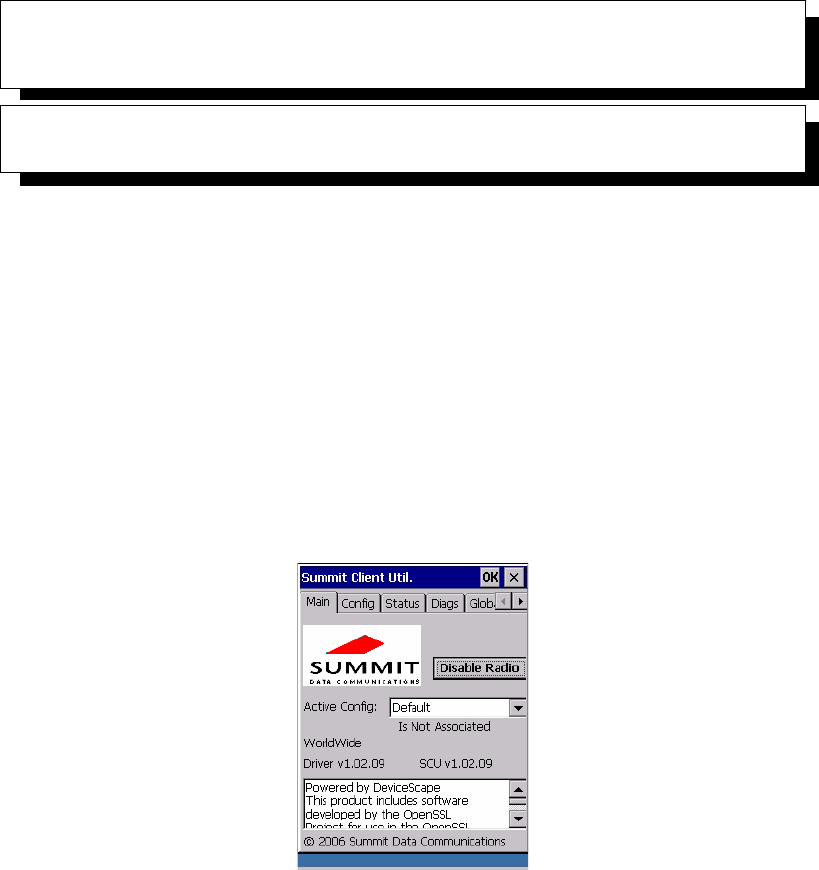
WORKABOUT PRO Hand-Held Computer With Windows CE 5.0 User Manual C-1
APPENDIX C
SUMMIT CLIENT UTILITY (SCU) FOR MODEL RA2041
This appendix provides details about each tab in the Summit Client Utility (SCU).
For quick, step-by-step setup instructions, refer to “Configuring The Summit
RA2041 802.11b/g” on page 13.
C.1 SCU Tabs
This section provides a detailed description of each of the tabs available in the
SCU—Main (below), Config (page 2), Global Settings (page 7), Status (page 9),
and Diags (page 10).
C.1.1 Main Tab
The Main tab is displayed when you tap on the Start>Programs>SCU icon.
•Enable/Disable Radio: Enables or disables the radio. This is a toggle
button; when the radio is enabled, this button reads Disable Radio, and
when the radio is disabled, the button reads Enable Radio.
•Active Config: Lists the name(s) of the active configuration profile(s)
which are referred to as “configs”. When a config is chosen from the Active
Config drop-down menu, the settings for that config become active.
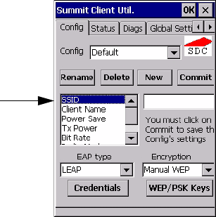
Appendix C: Summit Client Utility (SCU) For Model RA2041
Config Tab
C-2 WORKABOUT PRO Hand-Held Computer With Windows CE 5.0 User Manual
If ThirdPartyConfig is selected, after the WORKABOUT PRO goes
through a power cycle, WZC is used for configuration of the radio. See
“ThirdPartyConfig” on page 6 for details.
•Association Status: Indicates if the radio is associated to an access point. If
this is not the case, Association Status indicates the radio status.
•Software Version: This field displays the version of the device driver and
the SCU that are running on the WORKABOUT PRO.
•About Box: This box provides information about the SCU.
C.1.2 Config Tab
The Config tab allows you to define radio and security settings that are stored in the
registry as part of the configuration profile or config.
The config you create and save is listed in the Active Config drop-down menu in the
Main tab You can define up to 20 configs.
•Config: Used to choose the config to be viewed or edited. If ThirdParty-
Config is chosen, after the WORKABOUT PRO goes through a power
cycle, WZC is used for configuration of the radio.
•Rename: Allows you to assign a config name.
•Delete: Deletes the config unless it is currently active.
•New: Allows you to create a new config with default settings and assign it a
name.
•Commit: Saves all changes.
Radio
Attributes

WORKABOUT PRO Hand-Held Computer With Windows CE 5.0 User Manual C-3
Appendix C: Summit Client Utility (SCU) For Model RA2041
Config Tab
•Radio Attributes: Lists radio attributes. These attributes can be individu-
ally chosen from this menu. When an attribute is chosen, an associated
list of options is displayed where you can assign new settings or view
existing settings.
The following table describes the options in the Radio Attributes drop-down menu:
Radio Attribute Description Value Default
Config Name of config (configura-
tion profile). Use Rename
button to change name.
Maximum of 32 characters. None
SSID Service set identifier (SSID)
for WLAN to which the
radio connects.
Maximum of 32 characters. None
Client Name Name assigned to radio &
WORKABOUT PRO into
which it is installed.
Maximum of 16 characters. None
Power Save Power save mode for radio. CAM: Constantly awake.
Maximum: Maximum power
savings.
Fast: Fast power save mode.
Fast
Tx Power Maximum transmit power. Max: Maximum defined for
current regulatory domain.
Measured in mW: 50,30,10, 1.
Max
Bit Rate Used by radio when interact-
ing with WLAN access
point.
Auto: Rate automatically
negotiated with access point.
Rates in Mbps: 1, 2, 5.5, 6.9
11, 12, 18, 24, 36, 48, 54.
Auto
Radio Mode Used by 802.11g when inter-
acting with access point.
B rates only: 1, 2, 5.5, & 11
Mbps.
G rates only: 6, 9, 12, 18, 24,
36, 48, and 54 Mbps.
BG rates full: All B and G
rates.
BG rates optimized: 1, 2, 5.5,
6, 11, 24, 36 & 54 Mbps.
BG rates
opti-
mized
Auth Type 802.11 authentication type
used when associating with
access point.
Open, shared-key, or LEAP
(Network-EAP).
Open

Appendix C: Summit Client Utility (SCU) For Model RA2041
Config Tab
C-4 WORKABOUT PRO Hand-Held Computer With Windows CE 5.0 User Manual
•EAP-Type & Encryption: Security settings. These settings allow you to
enhance the security of data across the wireless LAN. Refer to “EAP Cre-
dentials” on page 6 and Section below, for details about these settings.
SCU Security Capabilities
The SCU provides integrated security to protect transmitted data as well as the hand-
held and wireless WAN infrastructure that transmit and receive data.
A foundational element of the IEEE 802.11i WLAN security standard is IEEE
802.1X and a critical application on a mobile device is an 802.1X supplicant. This
supplicant provides an interface between the radio and the operating system and
supports the authentication and encryption elements required for 802.11i, also
known as Wi-Fi Protected Access 2 (WPA2), as well as predecessors such as WPA
and WEP. Summit software includes an integrated supplicant that supports a broad
range of security capabilities, including:
• 802.1X authentication using pre-shared keys or an EAP type, required for
WPA2 and WPA.
• Data encryption and decryption using WPA2 AES, WPA TKIP or WEP.
Common EAP types include:
EAP Type Extensible Authentication
Protocol type used for 802.1X
authentication to access point.
None, LEAP, EAP-FAST,
PEAP-MSCHAP
– To use EAP-TLS, you must
use WZC.
None
Credentials Authentication credentials for
the selected EAP type.
Refer to “EAP Credentials”
on page 6.
User: Username or
Domain/Username (up to 64
characters).
Password: up to 64 characters.
For PEAP: CA Cert–CA server
certificate filename.
None
Encryption Type of encryption used to
protect transmitted data.
None, Manual WEP, Auto
WEP (generated during EAP
authentication), WPA PSK,
WPA TKIP, WPA2 PSK,
WPA2 TKIP, WPA2 AES,
CCKM TKIP.
For Manual WEP: Up to four
static WEP keys.
For PSK: ASCII passphrase or
hex PSK.
None
Radio Attribute Description Value Default

WORKABOUT PRO Hand-Held Computer With Windows CE 5.0 User Manual C-5
Appendix C: Summit Client Utility (SCU) For Model RA2041
Config Tab
•EAP-TLS: Uses the same technology as a follow-on to Secure Socket
Layer (SSL). It provides strong security, but relies on client certificates for
user authentication.
•PEAP: Provides secure user authentication by using a TLS tunnel to
encrypt EAP traffic. Two different inner methods are used with PEAP:
• EAP-MSCHAPV2, resulting in PEAP-MSCHAP: This is appropriate
for use against Windows Active Directory and domains.
• EAP-GTC, resulting in PEAP-GTC: This is for authentication with one-
time passwords (OTPs) against OTP databases such as SecureID.
•LEAP: Is an authentication method for use with Cisco WLAN access
points. LEAP does not require the use of server or client certificates. LEAP
supports Windows Active Directory and domains but requires the use of
strong passwords to avoid vulnerability to offline dictionary attacks.
•EAP-FAST: Is a successor to LEAP and does not require strong passwords
to protect against offline dictionary attacks. Like LEAP, EAP-FAST does
not require the use of server or client certificates and supports Windows
Active Directory and domains.
Note: PEAP and EAP-TLS require the use of Windows facilities for the configu-
ration of digital certificates.
SCU EAP Types
The following EAP types are supported by the integrated supplicant and can be
configured in SCU: PEAP-MSCHAP, PEAP-GTC, LEAP and EAP-FAST. With
each of these four types, if authentication credentials are not stored in the config,
you will be prompted to enter credentials the first time the radio attempts to
associate to an access point that supports 802.1X (EAP).
Consider the following when configuring one of the EAP types:
• PEAP-GTC: SCU supports static (login) passwords only.
• LEAP: Strong passwords are recommended.
• EAP-FAST: SCU supports automatic, not manual, PAC provisioning.
EAP-TLS will work with a RA2041 radio module when Windows Zero Config
(WZC) rather than the SCU is used to configure the type. With WZC, the native
Windows supplicant instead of the SCU integrated supplicant is used.
Appendix C: Summit Client Utility (SCU) For Model RA2041
Config Tab
C-6 WORKABOUT PRO Hand-Held Computer With Windows CE 5.0 User Manual
EAP Credentials
Keep the following in mind when defining security settings:
• If the credentials specified in the config are incorrect and that config is used,
the authentication fails without an error message; you will not be prompted
to enter correct credentials.
• If the credentials are not specified in the config, when the radio tries to asso-
ciate using that config, you will be prompted to enter the credentials.
• When prompted, you can enter valid credentials, enter invalid credentials,
or cancel the operation.
• If you enter valid credentials and tap OK, the radio will associate and
authenticate.
• If you enter invalid credentials and tap on OK, the radio will associate
but will not authenticate; you will be prompted again to enter creden-
tials.
• If you tap on Cancel or clear the credentials fields and tap on OK, the
radio will not attempt to associate with that config until you perform one
of the following actions (while the config is the active config):
• Cause the WORKABOUT PRO to go through a power cycle or sus-
pend/resume.
• Disable and enable the radio, or tap the Reconnect button on the Diags
windows.
• Modify the config, and tap on Commit.
Alternatively, you can choose another config as the active config and then switch
back to the config for which EAP authentication was cancelled.
ThirdPartyConfig
If you choose to configure ThirdPartyConfig, the SCU will work with the operating
system’s Windows Zero Config (WZC) to configure radio and security settings for
the CF radio installed in the unit.
Choosing this config means that WZC must be used to define the following radio
and security options: SSID, Auth Type, EAP Type and Encryption.The SCU settings
for ThirdPartyConfig include: Client Name, Power Save, Tx Power, Bit Rate and
Radio Mode. These SCU settings along with SCU global settings and the WZC
settings will be applied to the radio module.
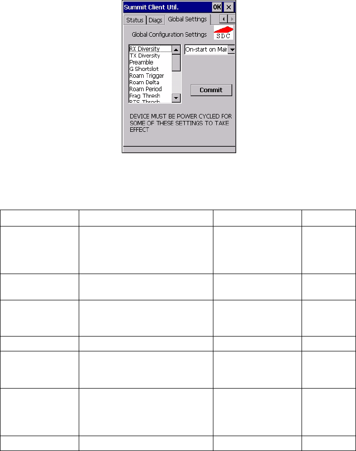
WORKABOUT PRO Hand-Held Computer With Windows CE 5.0 User Manual C-7
Appendix C: Summit Client Utility (SCU) For Model RA2041
Global Settings Tab
C.1.3 Global Settings Tab
The Global Settings tab allows you to define radio and security settings that apply to
all configs (profiles), along with settings that apply specifically to the SCU.
The Global Settings in the table below can be edited in the SCU:
Global Setting Description Value Default
CCX features Activates three CCX features:
AP-assisted roaming, AP-speci-
fied maximum transmit power
& radio management.
On, Off Off
Certs Path Directory where certificates for
EAP authentication are stored.
Valid directory path
up to 64 characters.
Dependent
on device.
Frag Thresh Packet is fragmented when
packet size (in bytes) exceeds
threshold.
Integer from 256 to
2346.
2346
G Shortslot 802.11g short slot timing mode. Auto, Off, On Auto
Admin Password Password that must be speci-
fied when Admin Login button
is pressed.
A string of up to 64
characters.
SUMMIT
Hide Passwords On - SCU as well as EAP
authentication dialog boxes hide
passwords, WEP keys and other
sensitive information.
On, Off Off
LED Available only with MCF10G. On, Off Off

Appendix C: Summit Client Utility (SCU) For Model RA2041
Global Settings Tab
C-8 WORKABOUT PRO Hand-Held Computer With Windows CE 5.0 User Manual
Preamble Type of radio preamble or head-
ers.
Auto, Short, Long Auto
Ping Payload Amount of data to be transmitted
on a ping.
Bytes: 32, 64, 128,
256, 512 & 1024
32
Ping Timeout ms Amount of time in milliseconds
that passes without a response
before ping request is consid-
ered a failure.
Integer from 0 to
30000.
5000
Ping Delay ms Amount of time in milliseconds
between successive ping
requests.
Integer from 0 to
7200000.
1000
Roam Delta Amount by which second AP’s
RSSI must exceed the moving
average RSSI for the current AP
before the radio will attempt to
roam to a second AP.
dBm: 5, 10, 15, 20,
25, 30, 35
15
Roam Period Following an association or roam
scan (with no roam), the number
of seconds the radio
collects RSSI scan data before
considering roaming.
Seconds: 5, 10, 15,
20, 25, 30, 35, 40,
45, 50, 55, 60
10
Roam Trigger If RSSI from AP is less than
roam trigger value, radio per-
forms roam scan or probes for an
AP with stronger signal.
dBm: -50, -55, -60,
-65, -70, -75
-70
RTS Thresh Packet size above which
RTS/CTS is required on link.
An integer from 0 to
2347.
2347
RX Diversity Defines how to handle antenna
diversity when receiving data
from AP.
-On-Start on Main:
On startup, use main
antenna.
-On-Start on Aux:
On startup, use auxil-
iary antenna.
-Main only: Use
main antenna only.
-Aux only: Use aux-
iliary antenna only.
On-Start on
Main
Global Setting Description Value Default
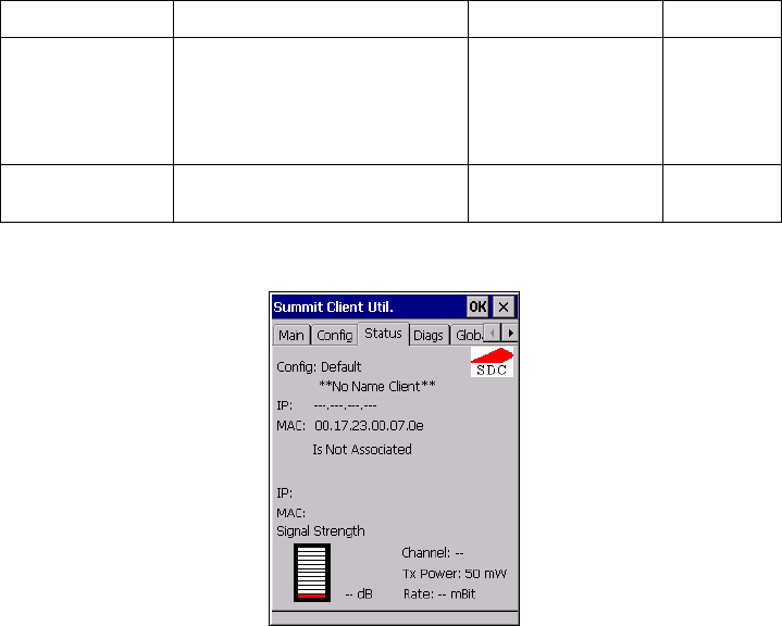
WORKABOUT PRO Hand-Held Computer With Windows CE 5.0 User Manual C-9
Appendix C: Summit Client Utility (SCU) For Model RA2041
Status Tab
C.1.4 Status Tab
The Status tab provides status information including IP address and MAC address
for the client radio, IP address and MAC address for the AP, signal strength,
channel, transmit power and data rate.
TX Diversity Defines how to handle antenna
diversity when transmitting data
to AP.
-Main only: Use
main antenna only.
-Aux only: Use aux-
iliary antenna only.
-On: Use diversity.
On
WMM Use Wi-Fi Multimedia Exten-
sions, also know as WMM.
On, Off Off
Global Setting Description Value Default
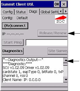
Appendix C: Summit Client Utility (SCU) For Model RA2041
Diags Tab
C-10 WORKABOUT PRO Hand-Held Computer With Windows CE 5.0 User Manual
C.1.5 Diags Tab
Use the Diags tab as a troubleshooting tool. The functions are as follows:
•(Re)Connect: Enables/Disables the radio, applies/reapplies current config
and tries to associate and authenticate to the wireless LAN, logging all
activity in the output area at bottom of the dialog box.
•Release/Renew: Obtains a new IP address through DHCP and logs all
activity in the output area.
•Start Ping: Starts a continuous ping to the address in the text box next to
this button. This is a toggle button so when you tap on it, it changes to Stop
Ping. Closing this window or tapping on another button also stops the ping.
•Diagnostics: Attempts to connect or reconnect to an AP, and provides a
more detailed dump of data than if you used (Re)connect. The dump
includes the radio state, config settings, global settings and BSSID list
of APs. The SCU is saved to a file called _sdc_diag.txt in the Windows
directory.
Ping Address
Ping Results

WORKABOUT PRO Hand-Held Computer With Windows CE 5.0 User Manual I
INDEX
A
Accepted Start Char 177
accessories
carrying case 212
desktop docking station 216
Ethernet adaptor cable 219
hand strap 209
holster, soft shell 212
pistol grip 211
port replicator 231
quad battery charger 223
quad docking station 225
single battery charger 221
vehicle cradle 228
Active Conn Tab 116
ActiveSync
ASync profile 112
Adaptive Windowing 193
adaptor cable
USB-Ethernet 219
Addendum 181, 194, 195, 196
Addendum Add-on 2 157, 158, 159, 160,
182
Addendum Add-on 5 157, 158, 159, 160,
182
Addendum Required 157, 158, 159, 160
Addendum Separator 157, 158, 159, 160
aiming dot, duration of 137
ALT Key 38
appearance (display colour scheme) 86
Append 156
appending to bar codes
characters 145, 200
arrow keys
moving the cursor 37
ASCII
Full Ascii 176
audio indicators
beep conditions 43
volume adjustment 44
Authentication, Bluetooth Controls 113
Auto Exposure (Imager) 192
Aztec, 2D 198
B
backlight
display 85
intensity 41
keyboard 41
backup battery (ML2032) 12
backup profile, creating (Total Recall) 124
backup profile, restoring (Total Recall)
128
Bad Scan Beep 201
bar code
appending to 145, 200
displaying type of bar code 201
parameters 135
prefix character 143, 144
stripping characters 143, 145
suffix character 143, 145
symbologies
Codabar 149, 161, 183, 196
Code 11 163, 185
Code 128 144, 194
Code 39 194
Code 93 148, 160, 182, 196
Discrete 2 of 5 151, 165, 186
EAN 13 144, 157, 179, 194
EAN 8 145, 158, 180, 195
IATA 2 of 5 164
Interleaved 2 of 5 150, 163, 185,
196
Matrix 2 of 5 164, 186
MSI Plessey 149, 162, 184
UPC A 145, 158, 180, 195
UPC E 146, 159, 181, 195
Translation tab 202
bar code reader
integrated scanner, operation of 232
Barcodes Must Decode 191
batteries
a description of 213
backup (ML2032) 12

II WORKABOUT PRO Hand-Held Computer With Windows CE 5.0 User Manual
Index
capacity dialog box 98
charging 11, 34
gauge 45
installing 33
installing main battery 12
main battery 11
pinouts A-2
power saving suspend dialog box 99
removing 33
run time 47
storing 47
swap time 33
battery charger
safety instructions 214–215
battery specifications 246
high-capacity (WA3006) 246
super high-capacity (WA3010) 250
beeper
beep conditions 43
volume adjustment 44
Bi-Direction Redundancy 139
BKSP (DEL Key) 38
Bluetooth devices, pairing 49, 111
Bluetooth radio
changing device name 116
device service profiles 112
ISM band 109
PINs for devices 113
radio configuration 109
Bluetooth setup 109
GPRS setup 117
peripherals 235
Bluetooth specs 246
BooSt
console (cold reset) 27
Bright For (backlight) 86
BSP, Bluetooth Controls 117
C
cable diagrams A-1
calibrating (touchscreen) 41, 103
Call Lists 22
Call Management 24
Captures Per HW Trigger 192
case, carrying 212
Center Bar Code Only (Imager) 190
CH, Bluetooth Controls 113
changing password (Start Menu security)
64
characters
appending to bar codes 145
prefix 143, 144
stripping 143, 145
suffix 143, 145
charger
descriptions of 34
safety instructions 214–215
chargers 213
desktop docking station 216
installing at a site 214
operator controls 214
quad battery charger (WA3004) 223
single battery 221
charging (main battery) 11
Check Char 155, 161, 162, 164
Check Digit 157, 158, 159
check digit 150, 163
Check Digit, One 150, 163
Check Digits (MSI Plessey) 150, 163
Check Digit Verification 142, 177, 179,
184, 185, 187
Check Digit Verification (Codabar) 183
Check Digit Verification (I 2 of 5) 151
cleaning hand-held 50
Click Data (scanner double-click) 200
Click Time (scanner double-click) 200
CLSI Editing 149
CLSI Library System 183
Codabar 149, 161, 183, 196
Codabar 149
Codablock 170, 189
Code 11 163, 185
Code 128 194
Code 128 144, 156, 178
Code 128 Emulation 153, 189
Code 16K 169
Code 32, Convert To 141
Code 32 Prefix 141
Code 39 141, 155, 176
Code 49 170
Code 93 148, 160, 182, 196
Code 93 148
cold reset 27
Cold Reset (Shutdown menu) 71
COM, Bluetooth Controls 117
Command Prompt 65
communication
Ethernet connection (desktop dock)
219
Ethernet connection (quad dock) 225
WORKABOUT to PC 218

WORKABOUT PRO Hand-Held Computer With Windows CE 5.0 User Manual III
Index
Composite 152, 167, 197
Concatenation 162
conference calls, creating 24
connection list table, Bluetooth Controls
116
Constant Illumination 194
Continuous Scan Mode 138, 154, 175,
190
control panel
accessing 79
basic setup 84
Display Properties 84
icons 80
keyboard properties 87
power management properties 98
stylus properties 103
Conv. UPC-E To UPC-A 147
Conv. UPC-E1 To UPC-A 147
Convert To Code 32 141
Convert To EAN 13 151, 180, 181
Convert To UPC -A 181
cradle See also Picker cradle 228
CTRL Key 38
cycle tasks 68
D
Data Matrix, 2D 170, 197
Decoded (HHP) parameters 154
decoded (internal) scanner parameters 137
decoded Intermec (ISCP) parameters 175
Decode Performance 142, 144
Decode Performance Level 143, 144
Decoder Timeout 193
DEL (BKSP) Key 38
Delete Char Set ECIs 140
Demo
Imager 65
Scanner 65
Signature 65
desktop connection, remote 79
desktop docking station (WA4002) 216
Device Name, changing 116
dialer (phone), using 20
Dialer (phone) icon 46
dialing, phone number 20, 21
dialog box, using 71
Diff Read Timeout 176
digit
check digit 150, 163
Dim For (backlight) 86
Discrete 2 of 5 151, 165, 186
Discrete 2 of 5 151, 165
dismounting partitions 131
display
appearance (colour scheme) 86
backlight 85
backlight, adjusting 41
Display Properties 84
Display Properties 84
docking device icons 46
docking station
uploading data using 48
docking stations 213
desktop docking station 216
installation at site 214
operator controls 214
quad dock 225
Dot Time 137, 191
double-click
appending characters to a decoded
bar code 200
scanner trigger 200
Double-Click, Manage Triggers menu
105
Double-Tap (stylus settings) 103
DSSS, 802.11b/g radio 244
DUN service, Bluetooth 112
Duration 137
E
EAN 13 144, 157, 179, 194
EAN 8 145, 158, 180, 195
EAN-8 Zero Extend 145
ECI Decoder 141
Enable Bookland (UPC-EAN) 147
Enable CC-AB 153
Enable CC-C 153
Enable Plessy 184
Enable RSS Expanded 152, 166, 188
Enable RSS Limited 152, 166, 188
Enable RSS-14 152, 188
Enable TLC-39 153, 168
Encryption, Bluetooth Controls 113
ESC Key 38
EV15 Specs 257
EV15 1D imager scanner specs 257
F
Factory Defaults On Reboot 191
Fast Converge (Imager) 192

IV WORKABOUT PRO Hand-Held Computer With Windows CE 5.0 User Manual
Index
features, WORKABOUT PRO 4
Field Size 143
Field Size/Chars (bar code scanning) 143
FNC1 Conversion 178
formatting
entire memory card 128
partitions 131
Full Ascii 176
Full ASCII (decoded scanner) 142, 156
Function Keys
accessing 38
G
Good Scan Beep 201
GPRS (Bluetooth) 117
GSM/GPRS B-1–B-17
GSM radio 244
GS1-128 178
GS1 128 (Composite bar code) 167
GS1-128 GS1 US 144
GS1-128 Identifier 178
GTIN Compliant 178, 182
H
hand strap 209
headsets, pairing (Bluetooth) 49, 111
high-capacity battery pack (WA3006) 246
holster, soft shell 212
I
IATA 2 of 5 164
Imager
EV15 specs 257
imager (2D) scanner
scanning
2D 234
imager options 232
imager parameters 190
indicators
battery gauge 45
dialer, phone 46
docking devices 46
LED functions 43
modifier keys 45
onscreen 44
phone dialer 46
scanner message 234, 235
security level 46
task bar 59
Wireless WAN 46
802.11radio signal quality 46
Input Panel (control panel) 81
integrated scanner option 232
Intensity (7035 backlighting) 85
Intensity, Keyboard Backlight 88
Interleaved 2 of 5 150, 163, 185, 196
Internet Explorer 65
IP address, assigning (Summit) 14
ISBN Conversion 157, 180
ISBT Concat Any Pair 179
ISBT Concatenation 156
ISBT Concat Transmit 178
ISBT 128 144, 178
ISM band, Bluetooth radio 109
K
keyboard
key repeat 87, 88
one shot mode 89
36-key keyboard 39
58-key 39
keyboard backlight 41
keyboard keys 36
ALT 38
arrow keys 37
BKSP 38
CTRL 38
DEL 38
ESC 38
macro keys 39, 90
modifiers 36
navigating using the keyboard 55
one shot mode 89
SCAN 38
SHIFT 37
SPACE 37
TAB 38
Keyboard Properties 87, 88
backlight 88
one shot mode 89
Key Repeat tab 87
keys
alpha keys, 36-key keyboard 39
L
LANAccessUsingPPP service, Bluetooth
112
Laser On Time 138, 154, 175
LED
functions 43
Length Mode 183, 186, 187

WORKABOUT PRO Hand-Held Computer With Windows CE 5.0 User Manual V
Index
LIF (Low Insert Force) port pinout A-1
Linear Decode 148
Linear Security Level 138
Low Power Timeout 138, 155, 176
L1, Set Length 142
L2, Set Length 142
M
Macro keys
accessing 39
executing a macro 91
Macros menu, accessing 90
recording and saving 90
maintenance (of hand-held) 50
Manage Triggers 104
Matrix 2 of 5 164, 186
Max Gain (Imager) 193
Max Illumination (Imager) 193
Maximum Length 155, 157, 161, 162,
163, 164, 165, 166, 167, 168, 169, 170,
171, 172, 173, 174
Max Integration (Imager) 193
Max Number Barcodes 190
memory card
creating partitions 129
formatting entire 128
formatting partition 131
messages
Scan Indicator 201
scanner warning message 201
Scan Result 201
Micro PDF-417 153, 169, 189, 197
Minimum Cancel Time 138, 154, 175
Minimum Length 155, 157, 161, 162,
163, 164, 165, 166, 167, 168, 169, 170,
171, 172, 173, 174, 177, 179, 182, 184,
185, 186, 188
Min Scan Duration 192
modem using VPN clients B-7
modifier keys 36
locking 37
One Shot Mode 89
unlocking 37
mounting partitions 132
MSI Plessey 149, 162, 184
N
name servers, assigning (Summit) 16
NOTIS Editing 149
NQuerty Retry, Bluetooth Controls 117
O
Off & On buttons 35
On & Off button 12, 35
One Check Digit 150, 163
one dimensional internal scanner 233
One Shot Mode 89
ON For 88
Output (Telepen) 165
P
pairing Bluetooth devices 49, 111
Parameter Scanning 138, 155, 157, 161,
162, 163, 164, 165, 166, 167, 168, 169,
170, 171, 172, 173, 174, 176, 177, 178,
179, 182, 184, 185, 186, 188
partitions
creating 129
deleting 131
dismounting 131
formatting 131
management 131
mounting 132
PC, connecting WORKABOUT to 218
PDF internal scanner
scanning
PDF internal 234
PDF-417 153, 168, 188, 197
Pharmaceutical 156
phone, dialing 20
Phonebook 24
Phone Dialer icon 46
phone number, dialing 20, 21
picker cradle
installing cable 229
PIN, Bluetooth Controls 112
pinouts A-1
PINs, Bluetooth devices 113
pistol grip 211
Plessey Maximum Length 163
Plessey Minimum Length 163
Plessy Transmit Check Digit 184
port pinouts A-1
Port Prefix, Bluetooth Controls 117
port replicator 231
ports
LIF (Low Insertion Force) A-1
tether A-1
PosiCode 167
Postal

VI WORKABOUT PRO Hand-Held Computer With Windows CE 5.0 User Manual
Index
Australian 173
Canadian 173
China 173
Japanese 173
Kix 174
Korean 174
PlaNET 172, 198
PostNET 172, 198
Royal 174, 199
powering up 12
Power Management Properties 98
battery capacity 98
suspend, power saving 99
Power Source 99
Prefix 140
Prefix Char 143, 144
Printer (serial service), Bluetooth 112
profile, creating backup 124
profile, restoring backup 128
Programs
Command Prompt 65
Internet Explorer 65
Remote Desktop Connection 65
Windows Explorer 65
protective case 212
punctuation marks, accessing (SHIFT
Key) 37
Q
quad battery charger 223
quad dock (WA4204-G2) 225
R
radio
Bluetooth 109
Bluetooth specs 246
GSM/SPRS/EDGE 244
IP address (Summit), assigning 14
name servers (Summit) 16
RA2041 radio specifications 244
RA3030-G2 GSM radio specifications
244
specifications 244
802.11b/g Direct Sequence SS 244
802.11signal quality 46
radio specifications 244
Raster Expand Rate (2D) 140
Raster Height (2D) 140
RA2041 radio specifications 244
RA3030-G2 GSM radio specifications 244
Reading Range 177, 179, 182, 185
recalibrating (touchscreen) 41, 103
remote connect 79
Remote Desktop Connection 65
Repeat Delay (between key repeats) 88
Repeat Rate (of key repeats) 88
Repeat tab (key repeat settings) 87
resetting the WORKABOUT PRO
BooSt menu, accessing 27
warm reset 26
RSS Code 152, 166, 188, 196
Run (Start Menu) 70
S
safety instructions
battery charger 214–215
scanner 232
safety warning, scanner 232
Same Read Timeout 176
Same Read Validate 176
Scan Data Format 140
Scan Indicator 201
SCAN Key 38
Scan Log File 201
scanner
Bi-Direction Redundancy 139
CLSI Editing 149
Codabar 149
Code 39 141
Continuous Scan Mode 138
Conv. UPC-E To UPC-A 147
Conv. UPC-E1 To UPC-A 147
decoded (internal) 137
decoded Intermec (ISCP) 175
EAN-8 Zero Extend 145
Enable Bookland 147
imager 190
Laser On Time 175
Linear Security Level 138
Low Power Timeout 138
Minimum Cancel Time 138
NOTIS Editing 149
one dimensional (1D) internal scanner
233
Parameter Scanning 138
PDF internal scanner dimensional (1D)
234
safety warnings 232
Security Level 148
Supp. Redundancy 147
Supplementals 147
techniques (scanning) 232

WORKABOUT PRO Hand-Held Computer With Windows CE 5.0 User Manual VII
Index
troubleshooting tips 233
two dimensional (2D) imager scanner
234
UPC-A Check Digit 145
UPC-A Preamble 146
UPC-EANI 147
UPC-E Check Digit 146
UPC-E Preamble 146
UPC-E1 Check Digit 146
UPC-E1 Preamble 146
2D UPC Half Block Stitching 148
scanner module (SE 955)
specs 254
scanner options 232
scanning
aiming (target) dot duration 137
appending characters 145, 200
Bad Scan Beep 201
check digit 150, 163
Check Digits (MSI Plessey) 150, 163
Check Digit Verification 142
Check Digit Verification (I 2 of 5) 151
Click Data (appending data) 200
Click Time 200
Code 128 144, 156, 178
Code 128 Emulation 153
Code 32 Prefix 141
Code 39 155, 176
Code 93 148
Composite 152
Convert To Code 32 141
Convert To EAN 13 151
Decoded (HHP) 154
Decode Perf. Level 143, 144
Decode Performance 142, 144
Delete Char Set ECIs 140
Discrete 2 of 5 151
Dot Time 137
double-click 200
ECI Decoder 141
Enable CC-AB 153
Enable CC-C 153
Enable RSS Expanded 152
Enable RSS Limited 152
Enable RSS-14 152
Enable TLC-39 153, 168
Full ASCII 142, 156
Good Scan Beep 201
Laser On Time 138, 154
Linear Decode 148
Micro PDF-417 153
PDF-417 153
Postal
PlaNET 198
PostNET 198
Royal 199
Prefix 140
prefix character 143, 144
removing characters 143, 145
RSS Code 152
safety instructions 232
Scan Data Format 140
Scan Indicator 201
Scan Log File 201
Scan Result 201
Scan Result Time 201
Set Length L1 142
Set Length L2 142
specifications 254
specifications, imager 258
Suffix 140
suffix character 143, 145
symbologies 135
target (aiming) dot duration 137
Translations tab 202
Transmit Check Digit 142
Transmit Check Digit (I 2 of 5) 151
Transmit Check Digit (MSI Plessey)
150
Transmit Code 1D Char 140
Trioptic Code 39 156
Trioptic Code 39, Enable 141
UPC-EAN Shared Settings 160, 181
1D internal 233
2D Maxicode 198
2D QR Code 197
Scanning Mode (2D) 139
Scan Result 201
Scan Result Time 201
screen
stylus, using to navigate 55
touch pen, using 55
Windows CE, navigating 55
SCU (Summit Client Utility) 14, C-1
Config Tab C-2
configuring 17
Diags (Diagnostics) Tab C-10
EAP Credentials C-6
EAP Types C-4, C-5
Global Settings Tab C-7
IP, assigning 14
Main Tab 17, C-1
security C-4
Status Tab C-9

VIII WORKABOUT PRO Hand-Held Computer With Windows CE 5.0 User Manual
Index
ThirdPartyConfig C-6
Windows Zero Config (WZC) C-6
WLAN, connecting to 14
SD/MMC Card, inserting 49
Security Level 148
security level icon 46
Security Settings 63
changing password 64
configuring taskbar 64
level 63
Supervisor 63
Teklogix 63
User 63
Servers, Bluetooth Controls 114
Services 23
Services, Bluetooth Controls 112
Set Length L1 142
Set Length L2 142
Set PIN, Bluetooth Controls 113
Settings
Control Panel 69
Network and Dial-up connections 69
Run 69
Taskbar and Start Menu 69
SE 955 scanner specs 254
SHIFT Key 37
Shutdown
Cold Reset 71
Suspend 70
Warm Reset 71
Shutdown (Start Menu) 70
signal quality, 802.11 46
SIM card, inserting 49
single battery charger (WA3001) 221
SIP (Soft Input Panel 81
Sled See vehicle cradle. 228
SMS Configuration B-16
Soft Input Panel (SIP) 81
Soft Scan Timeout 201
SPACE Key 37
specifications
SE 955 scanner 254
Start/Stop Transmit 161, 177, 183
Start Menu 62
cycle tasks 68
desktop 63
programs 65
Run 70
Security 63
Settings 69
Shutdown 70
system tray 67
task manager 68
Strip Leading 143, 145
Strip Start/Stop Chars 155
Strip Trailing 143, 145
stylus (touch pen), using 55
Stylus Properties 103
Double-tap (stylus sensitivity) 103
Suffix 140
Suffix Char 143, 145
Summit Client Utility (SCU) 14, C-1
super high-capacity battery pack
(WA3010) 250
Supervisor security level 63
Supp. Redundancy (Code 128) 147
Supplementals (UPC-EAN) 147
Suspend (Shutdown menu) 70
Suspend Timeout 99
swap time (for battery) 33
symbologies, bar code 135
system tray 67
T
TAB Key 38
target dot, duration of 137
taskbar
customizing 60
onscreen indicators
battery gauge 45
dialer, phone 46
docking devices 46
modifier keys 45
phone dialer 46
security level 46
Wireless WAN 46
802.11 radio signal quality 46
using 59
task manager 68
Teklogix security level 63
TekTerm application 79
Telepe n 165, 187
tether port pinout A-1
text conventions 4
TLC-39 168
Total Recall
backup profile, creating 124
backup profile, restoring 128
touch pen, using 55