Psion 7530RA1001 HANDHELD COMPUTER User Manual 8000007 Book
Psion Inc HANDHELD COMPUTER 8000007 Book
Psion >
Contents
- 1. USERS MANUAL 1
- 2. USERS MANUAL 2
- 3. USERS MANUAL 3
USERS MANUAL 3
Psion Teklogix 7530 Hand-Held Computer User Manual153
Chapter 6: Tekterm Application
The Tekterm Status Area
6.4 The Tekterm Status Area
Tekterm provides a status area just above the softkey labels. The status area indi-
cates the operating condition of the hand-held.
Figure 6.2 Status Area
Table 6.2 outlines the options displayed in the status area.
Table 6.2 Status Area
Status Area Indicators
Security Level
Within Tekterm The security level assigned within the Tekterm application is displayed in the
status area. One of the following is displayed – User, Supervisor or Teklogix.
View Mode When <CTRL><ALT><V> is typed to place the 7530 in View mode, this
information is displayed in the status area.

Chapter 6: Tekterm Application
TESS Emulation
154Psion Teklogix 7530 Hand-Held Computer User Manual
6.5 TESS Emulation
TESS (Teklogix Screen Subsystem) is the normal operating mode of Psion Teklogix
computers. Teklogix protocol emulation software resident on network controllers or
a Psion Teklogix Software Development Kit (SDK) and installed in the host
converts host screens to TESS commands. The 9150 Access Point is also equipped
with protocol emulation software.
Note: If the message “RESET: Press Enter” flashes at the bottom of the TESS
screen when you turn on the 7530, press the <ENTER> key once.
6.5.1 Configuration
Note: Each TESS session must have a unique name assigned to it. The title
you assign will be displayed in the Display Menu.
The process of renaming an existing TESS session and adding a new session is
described in the section titled, “Applications” on page 194.
A unique number must be assigned in the “Terminal #” parameter for each TESS
session. Refer to “Terminal #” in the section titled “TESS Settings” on page 212
for details.
6.5.2 Working With Multiple Sessions
To display another session in TESS:
• Go to the startup ‘Display Menu’. If you are in a TESS session, press
<CTRL><ALT><0> to go to the ‘Display Menu’.
• Type the letter corresponding to the application you want to launch.
For example, suppose the sessions are listed in the “Display Menu” as
‘D TESS1’ and ‘E TESS2’. To launch the session named TESS2, type
the letter e.
6.5.3 The Field Types
Fixed Field – displays information that cannot be changed from the keyboard.
Entry Field – allows the operator to enter data. This type of field is usually shown
as: “........”
Match Field – the host computer loads data in the format of the expected entry. If
the entered data does not match the expected format, the unit emits a long beep.

Psion Teklogix 7530 Hand-Held Computer User Manual155
Chapter 6: Tekterm Application
IBM 5250 Emulation Keys
Auto-tab Field – automatically moves the cursor to the next field when the current
field is filled.
Bar code only Field – is filled with data from a bar code reader. Keyboard entries
are not accepted in this type of field.
Serial I/O Field – is filled with data coming from a serial port. Keyboard input is
not accepted in this type of field.
6.5.4 IBM 5250 Emulation Keys
The following keys allow the Psion Teklogix computer to better emulate the
functions of a true IBM 5250 terminal.
Note: These keys are active at all times in TESS applications.
6.5.5 Data Entry
The 7530 accepts data until the operator presses a key that sends a transmission to
the host computer. The following actions cause the 7530 to transmit:
• Pressing a function key or the <ENTER> key (which is considered to be
<F0>) causes the 7530 to transmit.
• Completing data entry into a “transmit on entry” field also causes the
7530 to transmit.
Key Function Key Sequence Cursor Movement
Field Advance or
Tab <BLUE> <O>
(PgDn key)
Cursor moves to the first position in the next
input field. If already in the last field, the cursor
moves to the first input field on the screen.
Field Backspace <BLUE> <I>
(PgUp key)
Cursor moves to the beginning of the current
field. If already in the first position, the cursor
moves to beginning of the previous field.
Field Exit <BLUE> <P>
(End key)
Current field is cleared from the cursor position
to the end of the field, and the cursor moves to the
next input field.
Home <BLUE> <N>
(Home key) Cursor moves to the first input field on the screen.

Chapter 6: Tekterm Application
TESS Edit Modes And Cursor Movement
156Psion Teklogix 7530 Hand-Held Computer User Manual
There are several ways to configure the 7530 hand-held to complete a data field:
• Pressing <ENTER> after entering data.
• Pressing a function key after entering data.
• Pressing an arrow key after entering data.
• Filling an auto-tab field.
6.5.5.1 TESS Edit Modes And Cursor Movement
The TESS editing modes and cursor movements in each type of mode are described
in the table below.
Note: When the “Enter on Arr” parameter is disabled (set to “N”), the <UP>
and <DOWN> arrow keys do not complete an entry field. Refer to
page 225 for details about this parameter.
Field mode
Press <CTRL> fto enter field mode. In this mode, once data entry
into a field has been completed, the entry cannot be changed without
retyping the entire field.
In field mode, the <RIGHT> and <LEFT> arrow keys do not perform
any functions. Pressing the <UP> or <DOWN> arrow key completes
the entry field and then, moves the cursor to the previous or next field.
Fcursor mode
Press <CTRL> uto enter fcursor mode. In this mode, once data
entry into a field has been completed, the entry cannot be changed
without retyping the entire field.
In fcursor mode, the <UP>, <DOWN>, <LEFT> and <RIGHT>
arrow keys move the cursor between fields.
Insert mode
Press <CTRL> ito enter insert mode. In this mode, data can be
entered between two characters that have been previously entered.
In insert mode, the <RIGHT> and <LEFT> arrow keys move the
cursor right and left within a field. The <UP> and <DOWN> arrow
keys complete the entry field and move the cursor to the previous or
next field.
Replace mode
Press <CTRL> rto enter replace mode. In this mode, data can be
entered over previously entered characters.
In replace mode, the <RIGHT> and <LEFT> arrow keys move the
cursor to the right and left within a field. The <UP> and <DOWN>
arrow keys complete the entry field and move the cursor to the previ-
ous or next field.

Psion Teklogix 7530 Hand-Held Computer User Manual157
Chapter 6: Tekterm Application
<DEL> Key Behaviour In TESS
6.5.5.2 <DEL> Key Behaviour In TESS
Field mode
• In a left justified field, the <DEL> key erases all characters in the
field and places the cursor in the left most position of that field.
• In a right justified field, the <DEL> key erases all characters in the
field and places the cursor in the right most position of that field.
• If the <DEL> key is used to clear data in a field that has been
pre-filled by the host application, the field is flagged as modified
and the updated information is sent to the host in the next response
message.
Replace mode
• In both left and right justified fields, the <DEL> key erases charac-
ters beginning from the current cursor position to the end of the
field. The cursor remains in the same position in the field.
• If the <DEL> key is pressed while cursor is in the right most
position in the field, the 7530 emits a keyboard error beep.
• If the <DEL> key is used to clear data in a field that has been
pre-filled by the host application, the field is flagged as modified
and the updated information is sent to the host in the next response
message.
Insert mode
• In both left and right justified fields, the <DEL> key erases the
characters from one character position to right of the cursor to
the end of the field.
• If the <DEL> key is pressed while the cursor is in the right most
position in the field, the 7530 emits a keyboard error beep.
• If the <DEL> key is used to clear data in a field that has been
pre-filled by the host application, the field is flagged as modified
and the updated information is sent to the host in the next response
message.
Fcursor mode • Refer to “Field Mode” at the beginning of this table. The <DEL>
key operates in the same manner in “Fcursor mode” as it does in
“Field mode”.

Chapter 6: Tekterm Application
<BKSP> Key Behaviour In TESS
158Psion Teklogix 7530 Hand-Held Computer User Manual
6.5.5.3 <BKSP> Key Behaviour In TESS
Field mode
• In a left justified field, the <BKSP> key erases the character directly
to the left of the cursor and then moves the cursor one position to the
left. When the last character in the field is deleted, the field displays
the value that it contained before it was modified, and the field is
opened.
• In a right justified field, the <BKSP> key erases the character on
which the cursor is positioned and shifts the remaining characters to
the right by one position. When the last character in the field is
deleted, the field displays the value that it contained before it was
modified, and the field is opened.
• If the <BKSP> key is pressed when the field is empty, the 7530 emits
a keyboard error beep.
• The <BKSP> key does not delete data pre-filled by the host applica-
tion.
• If the <BKSP> key is pressed in a field that has not been modified, the
7530 emits a keyboard error beep.
• If data is entered into a field and is then deleted before the field is
completed, the field remains unmodified when the cursor leaves the
field or when the screen is transmitted.
Replace mode
• In a left justified field, the <BKSP> key erases the character on which
the cursor is positioned unless it is one position to the right of the last
character in the string; in this case, the <BKSP> key erases the char-
acter to the left of the cursor.
• In a right justified field, the <BKSP> key erases the character on
which the cursor is positioned. The remaining characters are then
shifted to the left of the cursor, and the cursor is shifted to the right by
one position.
• If the <BKSP> key is pressed while the cursor is in the right-most
character position of the field, the cursor does not shift to the left
when that character is erased; it remains in the right most position in
the field.
• When the last character in a field is erased, the field remains empty –
that is, any pre-filled data is not displayed. Pressing the <BKSP> key
in the empty field results in a keyboard error beep.
• The <BKSP> key can delete data pre-filled by the host application.
• If data is entered in a field and is then deleted before the field is com-
pleted, the field remains unmodified when the cursor leaves the field
or when the screen is transmitted.

Psion Teklogix 7530 Hand-Held Computer User Manual159
Chapter 6: Tekterm Application
TESS Status Message
6.5.6 TESS Status Message
• Press <CTRL> <S> to continuously display the status message in the
lower left corner of the screen.
• Press <CTRL> <W> to make this message appear only when the 7530
locks. The message should look similar to the sample below:
V6.0 fld 0.6
“V6.0” is the TESS version number. “fld” indicates that TESS is currently in field
mode. Insert and replace mode are represented as “ins” and “rep” respectively. The
number “0.6” indicates the response time of the last transmission in seconds. Press
<CTRL> <T> to display the unit number instead of the TESS version number.
Insert mode
• In a left justified field, the <BKSP> function erases the character on
which the cursor is positioned, unless it is at the right end of the char-
acter string; in this case, it erases the character to the left of the cursor.
When the last character in a field is erased, the field remains empty,
and any further <BKSP> functions in the empty field result in a key-
board error beep.
• In a right justified field, the <BKSP> function erases the character
that is to the right of the cursor and then shifts the data remaining to
the right one position.
• If the <BKSP> key is pressed while the cursor is in the right-most
character position of that field, the cursor does not shift to the left
when that character is erased; it remains in the right-most position
in the field.
• When the last character in a field is erased, the field remains empty –
i.e. any pre-filled data is not displayed. Pressing the BKSP key in the
empty field sounds a keyboard error beep.
• The <BKSP> key can delete data pre-filled by the host application.
• If data is entered into a field and then deleted before the field is com-
pleted, the field remains unmodified when the cursor leaves the field
or when the screen is transmitted.
Fcursor mode • Refer to “Field Mode” at the beginning of this table. The <BKSP>
key operates in exactly the same manner in “Fcursor mode” as it does
in “Field mode”.
Chapter 6: Tekterm Application
Lock Messages
160Psion Teklogix 7530 Hand-Held Computer User Manual
6.5.7 Lock Messages
When information is transmitted to the host computer, the keyboard locks to
prevent further data entry until the 7530 receives a reply. A locked state is
indicated by either “LOCK-B” (base) or “LOCK-H” (host) in the lower left
corner of the display.
When the reply is received by the 7530, the lock message disappears and the
keyboard can be used again.
6.5.8 Control Commands
A group of <CTRL> key commands can be used within TESS to dictate how the
7530 will operate under a variety of conditions.
• <CTRL> <P> – Reprints the last print page sent from the host. This key
combination will not print anything if a print page from the host was not
previously received at the 7530 hand-held.
• <CTRL> <S> – Displays the 7530 status continuously. Below is a sample
status line as it might appear at the bottom of your screen:
Lock-B/Lock-H fld enh “
application name
”
• <CTRL> <W> – Displays the 7530 status when the unit is in “Lock B” or
“Lock H” mode. The status line would be similar to the sample above.
• <CTRL><T> – Displays the 7530 status with the terminal number instead
of the name.
Lock-B/Lock-H rep “
terminal
nn
”
• <CTRL> <H> – Displays a menu of available hosts.
6.5.9 Resetting A TESS Session
Resetting a TESS session requires that <CTRL> C be pressed three times within a
two second period to generate the “RESET – User request” message.
• Press and hold down the <CTRL> key, and press the <C> key three times
within a two second period.
• Press <ENTER>.
This procedure restarts the TESS session without affecting the rest of the 7530.

Psion Teklogix 7530 Hand-Held Computer User Manual161
Chapter 6: Tekterm Application
The Local Menu
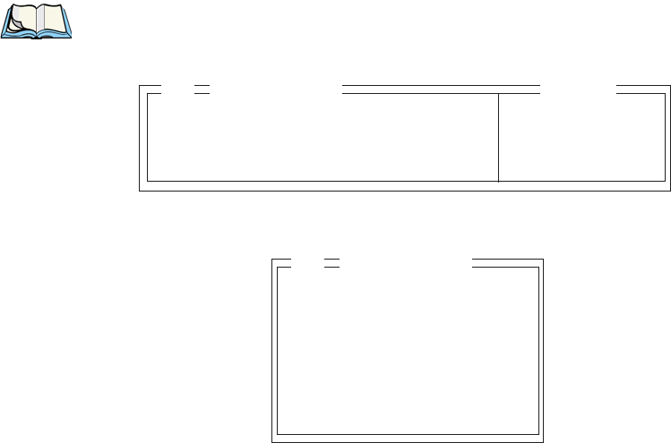
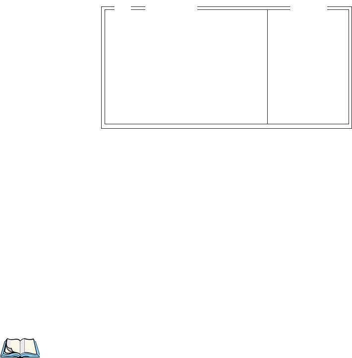
6.5.10 The Local Menu
The host can store local procedures in the 7530 for use when the unit is off-line.
A menu of these procedures appears whenever <CTRL> <L> is pressed
(see Figure 6.3).
• Press the function key corresponding to the procedure you want to perform.
Local procedures will not function when the “Lcl Process” and “Queuing”
parameters are disabled (see “Lcl Process – Save on Reset” on page 219
and “Queuing” on page 219).
Although using local procedures eliminates the advantages of an on-line 7530,
it allows work to continue when the host is unavailable. The “LOCK-B/H”
messages are replaced with “NEXT-B/H” in this mode.
Figure 6.3 Local Menu
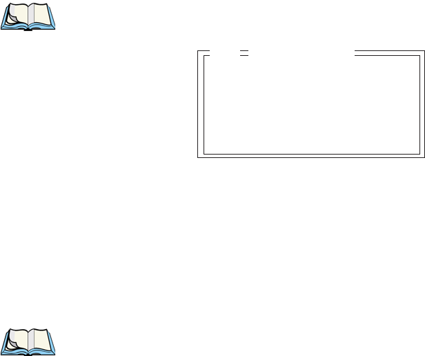
6.5.11 Selecting Another Host Computer
• Press <CTRL> <H> or <F9> from the local menu to display a menu of
available hosts.
This menu appears only when more than one host is available.
Figure 6.4 Select Host Screen
Note: This feature will not function when the “Lcl Process” and “Queuing”
parameters are disabled (see “Lcl Process – Save on Reset” on page 219
and “Queuing” on page 219).
LOCAL MENU
F1 -
F2 -
F3 -
F4 -
F5 -
F6 -
F7 -
F8 -
F9 - Select Host
Select Host: ......
F1 - Host 1 F2 - Host 2
Chapter 6: Tekterm Application
Queuing Mode
162Psion Teklogix 7530 Hand-Held Computer User Manual
6.5.12 Queuing Mode
In some applications, queuing mode can decrease the computer lock time. In queuing
mode, the host computer may send several pages to a 7530 without waiting for
a response. These pages are stored in a queue within the 7530 hand-held. The
operator completes the entries on the first page and then, presses a function key.
The 7530 simultaneously transmits to the host and displays the next page in the
queue. The computer does not lock, allowing the operator to enter data on the next
page immediately. This continues as long as there are pages in the queue.
Queuing mode is used for repetitive tasks, and the queued screens look identical.
The 7530 displays a “Next” message indicating that a new page is on the display.
“Next” messages also contain information about radio communications: “NEXT-B”
indicates that the 7530 has data to transmit to the base station. “NEXT-H”
indicates that the base station has acknowledged a transmission. Unlike lock
messages, “Next” messages do not lock the keyboard. Keying is allowed while
“Next” messages are displayed.
While queuing mode may improve apparent response time, it can present difficulties
to hosts that are operating in real time. It should only be used after careful
consideration of the host environment. The 7530 must be configured for queuing
mode (see the “Queuing” parameter on page 219). Additional information on
queuing can be found in the TESS (Teklogix Screen Subsystem) Manual.
6.6 ANSI Emulation
The Psion Teklogix 7530 in ANSI mode operates like most other ANSI terminals.
This means software that supports ANSI terminals requires little or no changes.
6.6.1 Configuration
To configure the 7530 for ANSI mode, the “Name” and “Type” of session – in this
case, ANSI – must be specified in the Applications menu. This menu is described in
the section titled, “Applications” on page 194.
Next, a unique number must be assigned using the “Terminal #” parameter. This
number should be unique across the entire system – that is, each 7530 and each
application session in each 7530 across your system must have a unique number
assigned. This parameter is described in the section titled “ANSI Settings” on
page 195.
Once the 7530 is configured, an ANSI operation can be selected from the startup
“Display Menu”.

Psion Teklogix 7530 Hand-Held Computer User Manual163
Chapter 6: Tekterm Application
Sending Data To The Host
6.6.2 Sending Data To The Host
7530 hand-helds running ANSI sessions transmit characters to the host as soon as
they are typed. The 7530 provides parameters that determine when the computer
transmits characters to the host.
The 7530 can be configured to transmit after a number of characters are typed
in (the “Xmit Count” parameter) or after some time has elapsed (the “Xmit Wait”
parameter), or both. This reduces overhead on the radio link and improves response
time. See page 202 for more information about these parameters.
You can also determine whether the 7530 transmits immediately after the
<ENTER> key, an arrow key, or a function key is pressed.
The 7530 computer also responds immediately to the device attribute requests
“CSIc”, “CSI0c” and “ESCZ”.
Note: For a more detailed description of the parameter settings for ANSI,
refer to “ANSI Settings” on page 195.
6.6.3 Psion Teklogix Keyboard And VT220 Equivalent Keys
The Psion Teklogix keyboard differs from most ANSI terminals. Table 6.3 maps the
equivalent VT220 keys.
Psion Teklogix Key Equivalent VT220 Key
<UP> arrow Up arrow
<DOWN> arrow Down arrow
<RIGHT> arrow Right arrow
<LEFT> arrow Left arrow
<F1>-<F4> PF1-PF4
<F5> None
<F6>-<F10> F6-F10
<F11> F11 (ESC)
<F12> F12 (BS)
<F13> F13 (LF)
<F14> F14
<F15> Help
<F16> Do
<F17>-<F20> F17-F20

Chapter 6: Tekterm Application
Block Mode (Local Editing)
164Psion Teklogix 7530 Hand-Held Computer User Manual
Table 6.3 Psion Teklogix Keyboard And VT220 Equivalent Keys
6.6.4 Block Mode (Local Editing)
The Psion Teklogix 7530s support “block mode” (or Local Editing). Application
programs must be specifically written to support this mode. For software that
supports this mode, the keys shown in Table 6.4 have special meaning.
Table 6.4 Function Of Keys In Block Mode
<F21> Find
<F22> Insert Here
<F23> Remove
<F24> Select
<F25> Previous Screen
<F26> Next Screen
<F27>-<F36> None
Key Function
<ENTER> Starts transmission of data.
Function keys Start transmission of data.
Arrow keys Move cursor to the next unprotected position in the
appropriate direction.
<SHIFT> <RIGHT> arrow Moves the cursor to the next unprotected area.
<SHIFT> <LEFT> arrow Moves the cursor to the previous unprotected area.
<DEL> Deletes the character to the left of the cursor, and moves
cursor one position to the left.
<CLR> Erases the data in an area and moves the cursor to the
first position in the area.
Psion Teklogix Key Equivalent VT220 Key

Psion Teklogix 7530 Hand-Held Computer User Manual165
Chapter 6: Tekterm Application
Working With Sessions
6.6.5 Working With Sessions
Important: Use only lowercase letters when entering commands
at the “TCP >” prompt.
6.6.5.1 Establishing A New Session
• Press <CTRL>, and type a lowercase a.
At the TCP> prompt:
• Type tel in lowercase letters followed by the Host Name or IP address.
• Press <ENTER>.
• Log in as usual to begin working with the new session.
6.6.5.2 Listing Sessions And Moving To Other Sessions
To list the current sessions:
• Press <CTRL>, and type a lowercase a.
At the TCP> prompt:
• Type sess in lowercase letters, and press <ENTER>.
To move to another session:
• At the TCP> prompt, type sess in lowercase letters followed by the session
number to which you want to move.
e.g., Type sess 2 to move to session 2.
• Press <ENTER>.
6.6.5.3 Closing A Session
To close a session:
• Press <CTRL>, and type a lowercase a.
• At the TCP> prompt, type cl in lowercase letters followed by the session
number you want to close.
e.g., Type cl 2 to close session 2.
• Press <ENTER>.

Chapter 6: Tekterm Application
Printing A Screen
166 Psion Teklogix 7535 Hand-Held Computer User Manual
6.6.5.4 Printing A Screen
To print each line of a screen with a CR/LF between each line:
• Press <CTRL>, and type p.
The screen will be printed using the port configured as “Print”.
6.6.5.5 Smart Echo – Disabling
In some circumstances – like entering a password – you many want to temporarily
disable “smart echo”, disguising the characters you type with ‘.’ (periods).
• Press <CTRL> <ALT> <P>, and type a ‘.’ (period).
• Type the necessary information using the keyboard, and then press
<ENTER> to return to “smart echo mode.
6.7 The Radio Statistics Screen
A radio statistics screen is automatically created when the Open Tekterm application
is launched.
To access the radios statistics screen, you’ll need to use the ‘Applications’ menu to
assign a radio title:
• In the ‘More Parameters’ menu, choose ‘Applications’.
• In the ‘Type’ field, choose RadioStats.
• In the ‘Title’ field, type a name for the radio screen – e.g., Radio.
• Press <F4> to save your changes, and then reset the 7535 – press and hold
down the <BLUE> and <ENTER> keys for a minimum of 6 seconds.
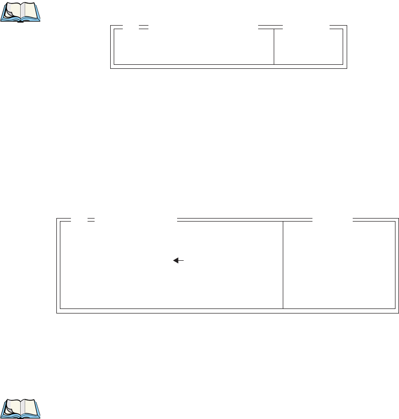
• In the ‘Display’ menu, type the letter corresponding to the radio statistics
screen. For example, in the sample screen below, you’d type d to display the
radio statistics screen.
A Parameters
B TESS
C ANSI
D Radio
01 Display Menu

Psion Teklogix 7535 Hand-Held Computer User Manual 167
Chapter 6: Tekterm Application
The Radio Statistics Screen
802.IQ Stats Screen
• AP/Controller mac MAC address of the Teklogix access point/controller
with which this 7535 is currently associated.
• Terminal MAC MAC address of the 7535 hand-held computer.
• bootnum e.g., C33B – the boot number of the network controller.
This number increments each time the controller reboots
so that 7535s can detect the reboot when they reinitialize.
• rm number of unique received messages.
• xm number of unique transmitted messages.
• rb number of received beacons. This number should contin-
uously increment.
• xi number of initializations with the network controller.
• ra number of received acknowledgements. (Normally, this
number should match the value in xm.)
• xa number of transmitted acknowledgements. (Normally,
this number should match the value in rm.)
• bt beacon timeouts. Number of times the beacon has not
been received as expected.
AP/Controller MAC 00:00:00:00
Terminal MAC 00:00:00:00:00:00
bootnum: C33B
rm 12 xm 7
rb 50 xi 1
ra 7 xa 12
bt 0 xr 1
rt (avg/lst) 10000: 0
fr:00 ar:00
fh:00 ah:00
ca:0 tn:0 sts:0
typ:0 msk:0 Q:0
AcQ:1 TxQ:1
-----Address Info-------------
Radio Address 0
End of statistics.
802.IQ Stats
Chapter 6: Tekterm Application
The Tekterm Startup Display Menu
168 Psion Teklogix 7535 Hand-Held Computer User Manual
• xr number of retransmissions. This number should remain
low if radio coverage is adequate.
• rt average round trip time. This number represents the milli-
seconds taken to send a message and receive a response
from the base station.
Cellular Protocol message numbers:
• fr forward remote number (hex).
• ar acknowledged remote number (hex).
• fh forward host number (hex).
• ah acknowledged host number (hex).
• ca radio address. This is the Cellular Address, including
session number (hex).
• tn host terminal number of session (decimal).
• sts session status (hex).
• typ data stream type (hex).
• msk message mask (hex).
• Q memory address of first message in receive queue (i.e. if 0
then the receive queue is empty).
• AcQ number of messages that have been sent but not yet
acknowledged by the Cellular Master (decimal).
• TxQ number of messages waiting to be sent (decimal).
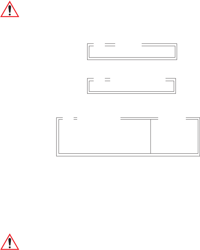
6.8 The Tekterm Startup Display Menu
The values assigned to Tekterm parameters can be viewed and adjusted to optimize
communication at the site in which a 7535 is operating. While some parameters are
accessible through the “Parameter Manager”, others can be adjusted through the
Windows CE Control Panel. This section provides a description of all parameters and
how to adjust them.
• Press <CTRL> <ALT> <0> (zero) to work with the ‘Display’ menu.
Psion Teklogix 7535 Hand-Held Computer User Manual 169
Chapter 6: Tekterm Application
Working With Menus
From this startup menu, you can launch the “Parameters” menu along with TESS
and/or ANSI sessions. You can also display the Radio Statistics screen.
Note: Aside from the ‘Parameters’ menu, all other applications listed in the
‘Display Menu’ are created in the ‘Applications’ menu. Refer to “Appli-
cations” on page 194 for details.
To launch an application, either type the letter to the left of the application you want
to use, or tap the stylus on the item.
For example, to display the “Parameters” menu:
• Type the letter a, or
• Tap the stylus on the “Parameters” item.
Note: To return to the ‘Display Menu’, press <F2> – the ‘Previous’ key.
6.9 Working With Menus
The 7535 offers two ways to navigate menus and choose values – you can either use
the keyboard or, if your unit is equipped with a touchscreen, you can select items
by tapping a stylus on the screen.
There are four types of parameters: numeric, Y/N, alpha and string entry. Some
menus have sub-menus attached to them and others utilize a Control Panel dialogue box
to make adjustments.
Important: Depending on the method you use when working with menus,
review either “Using The Keyboard To Navigate Through
Menus” on page 170 or “Using The Touchscreen To Navigate
Through Menus” on page 173.
A Parameters
B TESS
C ANSI
01 Display Menu
Chapter 6: Tekterm Application
Using The Keyboard To Navigate Through Menus
170 Psion Teklogix 7535 Hand-Held Computer User Manual
6.9.1 Using The Keyboard To Navigate Through Menus
• Press the <UP> and <DOWN> arrow keys to move the cursor up and down
the current menu.
The currently selected parameter name will be displayed in reverse video.
6.9.1.1 Sub-Menus
The “»” character appearing to the right of the menu item indicates that it has
a sub-menu.
Displaying Sub-Menus
To display a sub-menu:
• Use the <UP> and <DOWN> arrow keys to position the cursor on the
menu item with the sub-menu you want to display.
• Press <F1> – the “NEXT” menu function key.
Returning To The Previous Menu
• Press <F2> – the “PREV” function key, or
• Press <ESC>.
6.9.1.2 Numeric Parameters
Numeric parameters are displayed in reverse video. To increment or decrement
a number:
• Press the <RIGHT> or <LEFT> arrow keys, or
• Type the desired number in the field. Negative values are entered by typing
a “-” (minus) sign and then the number.
• Press <ENTER>.
Each numeric parameter has a preset range of numbers assigned to it – for example,
a preset range of 1 through 10. If you attempt to enter a number which either
exceeds 10 or falls below 1, the incorrect value will be rejected – the original value
for this parameter, if any, will be displayed.

Psion Teklogix 7535 Hand-Held Computer User Manual 171
Chapter 6: Tekterm Application
Y/N Parameters
6.9.1.3 Y/N Parameters
Y/N parameters can only be enabled (Y) or disabled (N). To enable or disable
a Y/N parameter:
• Press the <RIGHT> or <LEFT> arrow key once, or
• Type y to enable or n to disable the parameter.
Some Y/N parameters have sub-menus. For these parameters, a double right
arrow (») appears next to the “Y” or “N”.
6.9.1.4 Alpha Parameters
Alpha characters appear in reverse video in this type of parameter. The allowable
values for alpha parameters consist of a predetermined set of acceptable letters or
words. To cycle through the set:
• Press the <RIGHT> or <LEFT> arrow keys.
6.9.1.5 String Entry Parameters
Important: For detailed information about using string entry fields to
program macro keys, refer to “Macro Control Panel” on
page 181.
A sequence or string of characters can be entered in this type of parameter. When a
string entry parameter contains data, it is displayed in reverse video. (Empty fields
are not displayed in reverse video.) The methods that can be used to enter
information in string entry parameters are described in this section.
In string entry parameters, the <UP> arrow, <DOWN> arrow, <ENTER> and
<BKSP> keys have the following functions:
• The <UP> and <DOWN> arrow keys move the cursor between entry fields
in the direction of the arrow.
• <ENTER> completes the entry field.
• <BKSP> deletes the character to the left of the cursor.
• <DEL> (key combination <BLUE> <BKSP>) clears the entire field.

Chapter 6: Tekterm Application
String Entry Parameters
172 Psion Teklogix 7535 Hand-Held Computer User Manual
Choosing An ASCII Character With The Arrow Keys
Important: Make sure the <CTRL> and <SHIFT> keys are turned off!
By pressing either the <RIGHT> or <LEFT> arrow key, you can cycle through
a set of printable characters not directly accessible from the keyboard.
• Press the <RIGHT> arrow to display the next character in this sequence,
and the <LEFT> arrow to display the previous one.
Adding Additional ASCII Characters
When you’ve chosen an ASCII character and want to add another one in the same
field, the cursor must be moved to the right of the existing character. Normally,
pressing the <RIGHT> arrow key moves the cursor to the right, but in a string entry
field, pressing the <RIGHT> arrow key cycles through the available ASCII
characters instead. If you’ve already chosen an ASCII character and want to
add another one in the field, you need to take a few extra steps to move the cursor
to the right.
To add another ASCII character in the string entry field, next to the one you’ve
already chosen:
• Type a numeric character – for example, type the number 7.
• Next, press the <BKSP> key.
The cursor is now positioned to the right of the previously selected ASCII character.
• Press the <RIGHT> or <LEFT> arrow key to scroll through the ASCII
characters, and select another character.
Entering Information In A String Entry Field
In addition to using the fixed set of ASCII values assigned to this type of parameter,
you can also type text in a string entry field.
• Type the required text in the string entry field – including letters, numbers
and symbols.
• Press <ENTER> to save the text.

Psion Teklogix 7535 Hand-Held Computer User Manual 173
Chapter 6: Tekterm Application
Using The Touchscreen To Navigate Through Menus
Entering Unicode Values
Unicode is a trademark of The Unicode Consortium. To enter a Unicode™ value for
one-time use:
• Press and hold down the <ALT> key while typing a four digit decimal value
that represents the Unicode™ character you want to display.
• Release the <ALT> key.
Important: If you have a set of Unicode™ values that you use frequently, you
may want to create and save them in a pop-up window so that you
can access them whenever necessary. Refer to “Custom Charac-
ters (Unicode™)” on page 191 for details.
6.9.2 Using The Touchscreen To Navigate Through Menus
6.9.2.1 Sub-Menus
The “»” character appearing to the right of the menu item indicates that it has
a sub-menu.
Displaying Sub-Menus
To display a sub-menu:
• Tap the stylus on the menu item with the sub-menu you want
to display.
Returning To The Previous Menu
• If the softkey labels are visible at the bottom of the screen, tap the stylus on
the “PREV” (previous) softkey label.
• If the softkey labels are not visible, you’ll have to press <F2> – the “PREV”
function key.
Chapter 6: Tekterm Application
Numeric Parameters
174 Psion Teklogix 7535 Hand-Held Computer User Manual
6.9.2.2 Numeric Parameters
Numeric parameters are displayed in reverse video.
•To decrease the numeric value, tap the stylus on the left side of the number.
•To increase the numeric value, tap the stylus on the right side of the
number.
Each numeric parameter has a preset range of numbers assigned to it – for example,
a preset range of 1 through 10. If you attempt to enter a number which either
exceeds 10 or falls below 1, the incorrect value will be rejected – the original value
for this parameter, if any, will be displayed.
6.9.2.3 Y/N Parameters
Y/N parameters can only be enabled (Y) or disabled (N). To enable or disable
a Y/N parameter:
• Tap the stylus on the Y/N value – the value will toggle between “Y”
and “N”.
Some Y/N parameters have sub-menus. For these parameters, a double right
arrow (») appears next to the “Y” or “N”.
• Tap the stylus on the sub-menu arrow (») to display the sub-menu.
6.9.2.4 Alpha Parameters
Alpha characters appear in reverse video in this type of parameter. The allowable
values for this type of parameter consist of a predetermined set of acceptable letters
or words. To cycle through the set:
• Tap the stylus on the alpha field to cycle through the options.
6.9.2.5 String Entry Parameters
You’ll need to use the keyboard to enter values in string entry fields. Refer to “String
Entry Parameters” on page 171 for details.

Psion Teklogix 7535 Hand-Held Computer User Manual 175
Chapter 6: Tekterm Application
Saving Changes To Parameters
6.9.3 Saving Changes To Parameters
Whenever a parameter value is altered, the new value must be saved. To do this:
• Press <F4> – the “SAVE” key.
If you are using a touchscreen:
• Tap the stylus on the “SAVE” softkey label.
• If the softkey labels are not visible, you’ll have to press <F4> – the “SAVE”
function key.
If a parameter value is changed and the menu exited before the change is saved, a
dialogue box appears asking whether or not the operator wants to save the changes.
6.9.4 Retrieving Default Parameter Values
Important: When <F3> – the DEFAULT key – is pressed, all parameter
values revert to the factory defaults, including those values that
you’ve changed and saved.
• Press <F3> – the “DEFAULT” function key, or tap the stylus on the
“DEFAULT” softkey label – to reinstate the default parameter values.
• Press <F4> – the “SAVE” function key, or tap the stylus on the “SAVE”
softkey label – to save the changes.
• Reset the 7535. See "Resetting The 7535 Hand-Held Computer" in the next
section.
6.10 Resetting The 7535 Hand-Held Computer
Some parameter adjustments require that the 7535 be reset before the changes can
take effect. To reset the 7535:
• Press and hold down the <BLUE> key and the <ENTER/ON> key simulta-
neously for a minimum of six seconds.
A reset results in a complete reboot of the unit. All RAM memory contents are lost.
The contents of the flash memory and memory card are preserved. When the 7535 is
reset, the screen displays the Psion Teklogix and Microsoft® Windows® CE.net
splash screen before displaying the startup desktop.
Chapter 6: Tekterm Application
The Parameters Menu
176 Psion Teklogix 7535 Hand-Held Computer User Manual
6.11 The Parameters Menu
• At the ‘Display’ menu, type a to display the Parameters menu.
The “Parameters” menu allows you to adjust the screen contrast and select a security
level. With a Supervisory or Teklogix password, you can also access the parameters
listed in the “More Parameters” sub-menu.
6.11.1 Security Settings
To access the “More Parameters” sub-menus, the “Security” parameter must be set
to either a Supervisor or a Teklogix level password. The default security level is
User.
• Position the cursor on “Security”, and press the <RIGHT> arrow key to
display the Supervisor option.
• Press <ENTER>.
A Password screen is displayed.
• Type the supervisory level password – it is set at the factory to 123456.
• Press <ENTER>.
Changing A Password
Important: “Sup. Password” on page 186 describes how to change a supervi-
sory level password and how to change “User” options.
More Parameters » see page 177
Security User see page 176
Display » see page 177
01 Parameters Range
More Parameters » see page 177
Security User see text
Display » see text
01 Parameters Range
. . . . . .
Password
Psion Teklogix 7535 Hand-Held Computer User Manual 177
Chapter 6: Tekterm Application
Display Options
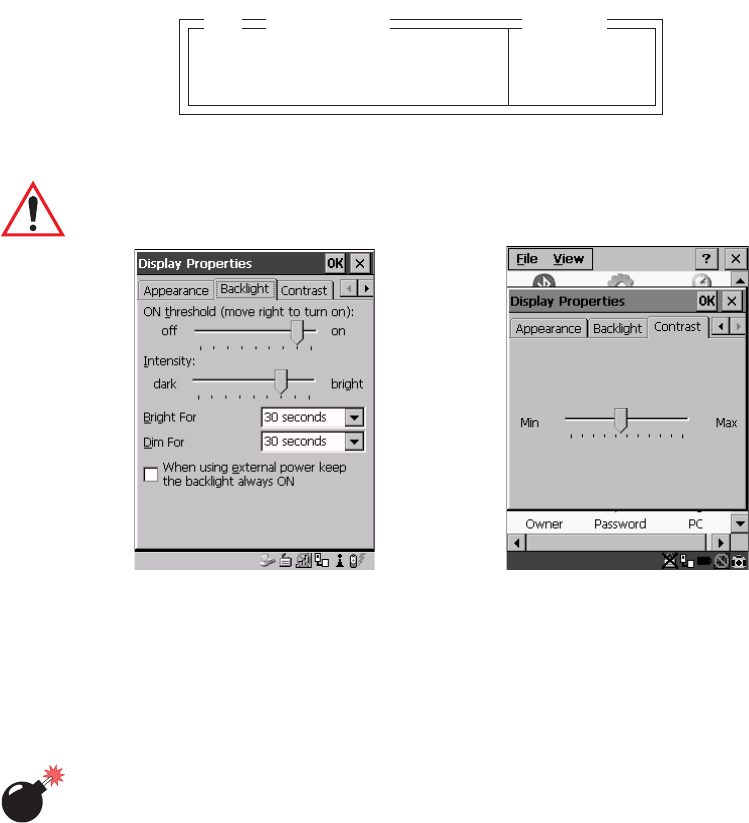
6.12 Display Options
The ‘Display’ sub-menu is used to adjust your unit’s display properties.
• Press <F1> to access the ‘Display’ sub-menu.
The Display Properties dialogue box is displayed where you can adjust the appearance,
backlight and contrast of your 7535 display.
Important: ‘Display Properties’ dialogue box options are described in detail
beginning on page 88.
Figure 6.5 Display Properties
6.13 More Parameters
The “More Parameters” sub-menus contain the Tekterm parameters and can only be
accessed with the proper security password – either a Supervisory or a Teklogix
password. (Refer to “Security Settings” on page 176 for details.)
Warning: Parameters should not be altered without a clear understanding of
how they operate. Parameters that are incorrectly set can increase
response time or cause communication difficulties. Generally,
parameters are configured for each site during installation.
Backlight Ctrl Panel » see text
Contrast Ctrl Panel » see text
02 Range
Display
Chapter 6: Tekterm Application
More Parameters
178 Psion Teklogix 7535 Hand-Held Computer User Manual
Note: Parameters can also be remotely modified using SNMP. Refer to “SNMP
(Simple Network Management Protocol) Setup” on page 134 for details.
• At the startup ‘Display’ menu, type ‘a’ to display the ‘Parameters’ menu.
• To open the ‘More Parameters’ menu, press <F1>.
More Parameters » see page 177
Security Supervisor see page 176
Display » see page 177
01 Parameters Range
Radio »
System »
Scanner Ctrl Panel »
View Manager »
Applications »
Ports »
Network »
02 Parameters
Psion Teklogix 7535 Hand-Held Computer User Manual 179
Chapter 6: Tekterm Application
Radio Parameters
6.14 Radio Parameters
Important: Radio parameters should not be changed from their factory
settings without a clear understanding of your system.
The 7535 is equipped with an Intel 802.11b radio.
• Press <F1> to display the ‘Radio’ sub-menu.
• Press <F1> to access the ‘802.11’ sub-menu.
• Set ‘802.IQ v1’ to ‘Y’ to activate these parameters. and press <F1> to
display ‘802.IQ v1’ parameters.
802.IQ v1
When 802.IQ v1 is set to “Y”, the attached sub-menu of parameters is enabled.
Auto Radio Addr
If this parameter is enabled (set to “Y”), a request is sent to the network controller to
assign a radio address to the hand-held computer radio.
If “Auto Radio Addr” is set to “N”, the value entered in the “Radio Address”
parameter is used. (Refer to "Radio Address" in this section for details about
manually assigned radio addresses.)
Important: Ensure that all 7535s grouped in the system use the same
addressing process – that is, if you choose to use automatic
radio addressing, use this addressing process for all units
operating in the same system. If you choose to assign radio
addresses manually using the “Radio Address” parameter, use
this process for all units in the same system.
802.11 »
03 Radio
802.IQ v1 N »
04 802.11 DS SS
Auto Radio Addr Y Y/N
Radio Address 0 1-3840
Initial RTT 0 0-1000
Protocol Type 2457 1501-65535
Range
802.IQ v1
05

Chapter 6: Tekterm Application
System Parameters
180 Psion Teklogix 7535 Hand-Held Computer User Manual
Radio Address
The value entered in the “Radio address” parameter is used to identify the
7535 over the radio link. A unique value from 1 to 3840 must be assigned
for each 7535 hand-held computer.
Initial RTT (Round Trip Time)
Round trip time is the elapsed time between a hand-held computer transmission and
an access point acknowledgement. Each 7535 continuously adjusts the acceptable
round trip time, calculating the average elapsed time over a number of transmis-
sions. If an acknowledgement takes longer to receive than the average round trip
time calculated, the computer will resend the transmission.
Because 7535s cannot calculate an average round trip time without a number of
transmissions, a starting point or “Initial Round Trip Time” is required. The com-
puter uses the time assigned to the “Initial RTT” parameter as a starting value for
round trip calculations. Once the 7535 begins transmitting and receiving data, this
value will be adjusted to reflect the actual average round trip time between transmis-
sions and acknowledgements.
Protocol Type
“Protocol Type” is used to identify the Ethernet packet frame type sent by the 7535.
The default value – 2457 – assigned to this parameter identifies the Teklogix 802.IQ
protocol Ethernet packet frame types.
The “Protocol Type ID” should only be altered if the default value is already being
used to specify another application Ethernet frame type.
Important: If you change the value assigned to “Protocol Type ID”, ensure
that all 7535s and 9150s in your system use the same number.
6.15 System Parameters
Keyboard »
Audio »
Pwr Mgmt Ctrl Panel »
Security »
03 System
Psion Teklogix 7535 Hand-Held Computer User Manual 181
Chapter 6: Tekterm Application
Keyboard
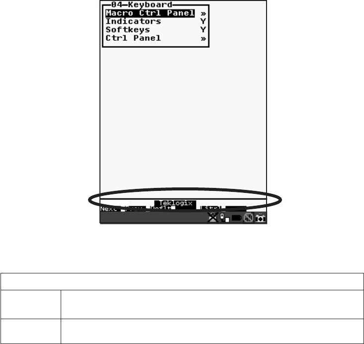
6.15.1 Keyboard
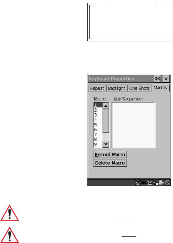
6.15.1.1 Macro Control Panel
• Highlight ‘Macro Ctrl Panel’, and press <F1> to display the Macros tab in the
Keyboard Properties dialogue box.
Figure 6.6 Macro Dialogue Box
Important: Refer to “Keyboard Macro Keys” on page 95 for detailed
instructions about creating macros.
Important: For information about using the macro keys you’ve created, refer
to “Macro Keys” on page 149.
Macro Ctrl Panel »
Indicators Y
Softkeys Y
Ctrl Panel »
Keyboard
04
Chapter 6: Tekterm Application
Indicators
182 Psion Teklogix 7535 Hand-Held Computer User Manual
6.15.1.2 Indicators
When the “Indicators” parameter is enabled (set to “Y”), onscreen indicators are
displayed to indicate the operating condition of the 7535. Refer to “Onscreen
Indicators” on page 45 for a list of possible indicators.
6.15.1.3 Softkeys
Enabling (setting to “Y”) the “Softkeys” parameter displays softkey labels at the
bottom of the screen to indicate the function of each softkey. To block the display of
softkey labels, set this parameter to “N”.
Softkeys are function keys which are programmed to execute specific actions when
pressed. Refer to Table 6.1 on page 149 for a list of softkey labels.
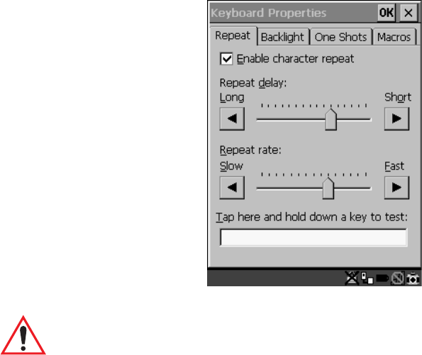
6.15.1.4 Ctrl Panel
This menu item displays the Keyboard Properties dialogue box in which you can adjust
the repeat rate of the keys, the intensity of the keyboard backlight and the behaviour
of the <BLUE> and <ORANGE> keys.
Figure 6.7 Keyboard Properties
Important: Refer to “Keyboard Properties” on page 92 for details about this
dialogue box.

Psion Teklogix 7535 Hand-Held Computer User Manual 183
Chapter 6: Tekterm Application
Audio
6.15.2 Audio
Beep Tone And Beep Time
These parameters regulate the frequency and duration of beeps emitted in a TESS or
ANSI session when one of the following is received at the 7535: an advisory, a hey
you or a bell character. Tone is measured in hertz and time in milliseconds.
Error Tone And Error Time
These parameters determine the frequency and duration of each error tone. Tone is
measured in hertz and time in milliseconds.
Scan Tone 1 And Scan Time 1
“Scan tone 1” and “Scan time 1” determine the frequency and duration of the first
beep of a multiple beep. Tone is measured in hertz and time in milliseconds.
Scan Tone 2 And Scan Time 2
“Scan tone 2” and “Scan time 2” determine the frequency and duration of the
second beep of a multiple beep. Tone is measured in hertz and time in milliseconds.
Scan Tone 3 And Scan Time 3
“Scan tone 3” and “Scan time 3” determine the frequency and duration of the third
beep of a multiple beep. Tone is measured in hertz and time in milliseconds.
Beep Tone 3000 800-3000
Beep Time 250 0-2000
Error Tone 1000 800-3000
Error Time 1000 0-2000
Scan Tone 1 1500 800-3000
Scan Time 1 100 0-2000
Scan Tone 2 2000 800-3000
Scan Time 2 100 0-2000
Scan Tone 3 2500 800-3000
Scan Time 3 100 0-2000
Sounds Ctrl Panel » see text
Range
Audio
04
Chapter 6: Tekterm Application
Power Mgmt Ctrl Panel
184 Psion Teklogix 7535 Hand-Held Computer User Manual
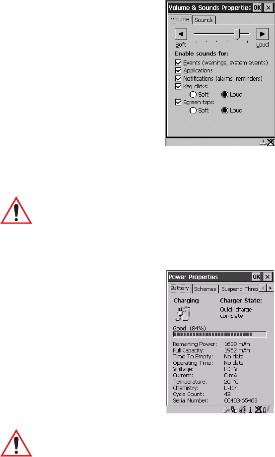
Sounds Ctrl Panel
This option displays the Volume & Sounds Properties dialogue box.
Figure 6.8 Adjusting The Volume
This dialogue box is used adjust the beeper volume and to select the conditions
under which the 7535 will emit a beep.
Important: Refer to “Volume And Sound Properties” on page 99 for details
about this dialogue box.
6.15.3 Power Mgmt Ctrl Panel
This menu item displays the Power Properties dialogue box.
Figure 6.9 Power Properties Dialogue Box
Important: Refer to “Power Management Properties” on page 100 for details
about this dialogue box.
Psion Teklogix 7535 Hand-Held Computer User Manual 185
Chapter 6: Tekterm Application
Security
6.15.4 Security
6.15.4.1 Default Mode
The value assigned to this parameter determines the operator’s level of access to
7535 parameters. The allowable values are User, Supervisor and Teklogix. “Default
mode” is set to User.
At User level, the operator is restricted to a small group of parameters. These are
listed in the “User” sub-menu. Refer to “User Level Options” on page 185 for
details. Choosing Supervisor allows access to all the parameters available in the
7535.
The Teklogix level password is only available to Psion Teklogix personnel.
• Press the <LEFT> or <RIGHT> arrow key to select the appropriate security
level – User, Supervisor or Teklogix.
6.15.4.2 User Level Options
Important: Only Supervisor and Teklogix level passwords can change the
values of the User options.
Screen Switch
When set to “Y”, the operator can use the “Split screen” parameter to toggle
between screens when multiple applications are running on the 7535. Refer to “Split
Screen” on page 188 for details about using this function.
Default mode User Supervisor, Teklogix
User » see text
Sup. password ###### see text
Allow Teklogix Y Y/N
Security
04 Range
Screen switch Y Y/N
View Mode Y Y/N
Font Chg Y Y/N
User
05 Range

Chapter 6: Tekterm Application
Sup. Password
186 Psion Teklogix 7535 Hand-Held Computer User Manual
Font Chg
When “Font Chg” is set to “Y”, operators at the User level can change the font size
of their 7535s.
6.15.4.3 Sup. Password
Note: Only a Supervisor or Teklogix level password can change the Supervisor
password.
The supervisory password is set at the factory to 123456. You should change the
default password to better protect the 7535 settings. When you’ve changed the
password, write down the new password and file it in a secure place. If the
password is lost, the parameters can only be changed by Psion Teklogix personnel.
Your password can have up to six alphanumeric characters. To change your
password:
• Position the cursor on “Sup. password” and type a new value in the string
entry field.
• When you’ve completed the change, press <ENTER> and then, press <F4>
– the SAVE function key – to save your change.
Important: When you change your password, set all the 7535s to the same
password.
6.15.4.4 Allow Teklogix
Setting this parameter to “Y” allows Psion Teklogix personnel to use their support
level password to access 7535 parameters. If ‘Allow Teklogix’ is set to “N”, only
your supervisory level password can be used to access the parameters.
Warning: If you set this parameter to “N”, the Psion Teklogix support level
password will be rejected. Keep in mind that if you then lose your
supervisory level password, you will need to clear the entire config-
uration setup on all terminals to gain access to the parameters
menu.
Psion Teklogix 7535 Hand-Held Computer User Manual 187
Chapter 6: Tekterm Application
Scanner Control Panel
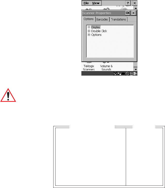
6.16 Scanner Control Panel
This menu item displays a Scanner Properties dialogue box in which you can set up the
particulars of your unit’s scanner performance, choose the bar codes which will be
decoded, and so on.
Figure 6.10 Scanner Properties Dialogue Box
Important: Refer to "Scanner Properties Setup" beginning on page 118 for
details about setting up your scanner.
6.17 View Manager
Display Shift
If this parameter is enabled (set to “Y”), the display in application screens shifts so
that there are no blank columns on the left-most side of the display.
Display Shift YY/N
Block Cursor Y Y/N
Use Increment N Y/N
X-increment 5 1..40
Y-increment 5 1..12
Split Screen » see text
Custom Chars » see text
Font Override N» see text
Default Colours » see text
View Manager
Range

Chapter 6: Tekterm Application
Split Screen
188 Psion Teklogix 7535 Hand-Held Computer User Manual
Block Cursor
When this parameter is enabled (set to “Y”), the cursor is presented as a flashing
block. When “Block Cursor” is set to “N”, the cursor is presented as a flashing
underline character.
Use increment
When “Use increment” is enabled (set to “Y”) and the cursor is moved off the
display, the screen contents shift by the values specified in the “X-increment” and
“Y-increment” parameters.
X-increment
This parameter determines the number of spaces the screen shifts once the cursor
moves out of view. The value assigned here doesn’t take effect until “Use
Increment” is set to “Y”.
Y-increment
This parameter determines the number of spaces the screen shifts once the cursor
moves out of view. The value assigned here doesn’t take effect until “Use
Increment” is set to “Y”.
6.17.1 Split Screen
This parameter allows you to split the display view so that more than one
application screen can be displayed at the same time. The split screen parameters,
“Type” and “View IDs”, are used to tailor the screen view for your needs.
Type And View IDs
The “Type” parameter determines how a screen will be split. The 7535 supports up
to four application screens. The “View IDs” parameter determines which
application screens will be displayed in each pane of the split screen. “Moving
Between Split Screens” on page 190 describes how to move the cursor from one
split screen to the next.
Type 2 Way |||
View IDs A
04 Split screen

Psion Teklogix 7535 Hand-Held Computer User Manual 189
Chapter 6: Tekterm Application
Splitting And Displaying Screens
6.17.1.1 Splitting And Displaying Screens
Before splitting the screen, you need to determine which applications should appear
in each pane of the split screen. The available applications are listed in the main
“Display Menu”. Each application listed in the “Display Menu” is preceded by a
letter – for example, Parameters is preceded by an A. This letter is used in the
“View IDs” string entry field to fix each pane of a split screen to a corresponding
application.
If you need to display the startup “Display Menu”:
• Press <CTRL> <ALT><0>.
To split a screen:
• With the cursor on the “Type” parameter, use the <RIGHT> or <LEFT>
arrow key to scroll through the types of split screens available.
The vertical and horizontal lines displayed at the “Type” parameter indicate how the
screen will be split – for example, in the sample screen on page 190, the vertical
lines indicate the screen will be vertically split into two segments. The screen can
also be split horizontally 3 ways or 4 ways.
Once you’ve indicated how you want to split the screen in the “Type” parameter:
• Use the <DOWN> arrow key to move the cursor to the “View IDs”
parameter.
• For each application you want to display, type the letter corresponding to
the application.
For example, suppose you want to split the screen into two vertical
segments with the Parameters menu in the left pane of the screen and
a TESS session in the right pane. In the “Display Menu”, the letter A
represents “Parameters” and B represents “TESS”. The “Type” and
“View ID” values would be represented as follows:
• Press <ENTER>.
To display the split screen on the 7535:
• Press <CTRL> <DOWN> arrow.
Type 2 Way |||
View IDs AB
04 Split screen

Chapter 6: Tekterm Application
Moving Between Split Screens
190 Psion Teklogix 7535 Hand-Held Computer User Manual
6.17.1.2 Moving Between Split Screens
To move the cursor from one pane in a split screen to the next:
• Press <CTRL> <RIGHT> or <LEFT>. The cursor moves in order from the
left-most pane to the right and from the top-most pane to the bottom.
6.17.1.3 Toggling Between Full & Split Screens
To toggle between a split and full screen format:
• Press <CTRL> <DOWN> arrow.
The application displayed when toggling from a split to a full screen format is
determined by the cursor location in the split screen. For example, if the cursor
is in the pane of a split screen in which the TESS application is displayed and
<CTRL> <DOWN> is pressed to display a full screen, the TESS application will be
displayed in the full screen.
6.17.1.4 Using The Asterisk As A Wild Card
When a screen is split, the application displayed in each pane is fixed in the “View
IDs” parameter. Using an asterisk * in the “View IDs” parameter indicates that a
particular pane in the split screen is not fixed to any particular application and can be
changed as required.
For example, suppose you want to split the screen into two vertical segments with
the left pane containing the “Parameters” menu and the right pane containing no
fixed application. The “Type” and “View IDs” parameters would be completed as
follows:
To change the application displayed in the pane with no fixed application:
• If the cursor is not currently in the pane, press <CTRL> <RIGHT> or
<LEFT> arrow to move the cursor into the appropriate screen.
• Press <CTRL> <ALT><0> to display the startup “Display Menu”.
• Type the letter corresponding to the new application you want to display.
Type 2 Way |||
View IDs A*
04 Split screen
Psion Teklogix 7535 Hand-Held Computer User Manual 191
Chapter 6: Tekterm Application
Custom Characters (Unicode™)
6.17.2 Custom Characters (Unicode™)
Note: The Unicode ™ characters created here are accessible only within the
Tekterm application. To create Unicode ™ characters that are accessible
system-wide, refer to “Unicode Mapping” on page 97.
The “Custom Characters” parameter allows you to create Unicode™ characters not
available directly from the keyboard, including accented characters. Unicode is a
trademark of The Unicode Consortium. You can create up to 20 Unicode™
characters that will be stored in a pop-up menu accessible from any application.
6.17.2.1 Creating A Unicode™ Character
Note: You can create a Unicode™ character by pressing and holding down
the <ALT> while typing the decimal value that represents the Unicode™
character you want to use. However, you will need to press <ALT> and
retype the decimal value each time you want to use the special character.
The advantage to creating special characters using the “Custom Chars”
parameters is that the characters you create in the customer characters
table are saved in a pop-up window that is accessible from any application.
• In the Parameters menu, highlight “View Manager” and press <F1>.
• Highlight “Custom Chars”, and press <F1> to display the custom
characters table.
• Position the cursor on the Fonts at the top of the table.
• Press the <LEFT> or <RIGHT> arrow keys until the character set you want
to use is displayed.
You can create up to 20 Unicode™ characters in the custom characters table.
To create a Unicode™ value:
• Replace the 0000 value with a hex value that represents the Unicode™
character you want to use.
Font Small
U+ 0000
U+ 0000
•
•
•
04 Custom Chars

Chapter 6: Tekterm Application
Displaying The Unicode™ Pop-up Window
192 Psion Teklogix 7535 Hand-Held Computer User Manual
• Press the <DOWN> arrow key to accept the value and move the cursor to
the next field.
When you have finished creating the Unicode™ characters you want to use:
• Press <F4> to save your changes.
• Reset the 7535 – press and hold down the <ENTER> and <BLUE> key
simultaneously for a minimum of six seconds.
6.17.2.2 Displaying The Unicode™ Pop-up Window
The Unicode™ values you create are stored in a pop-up window that you can access
from any application.
To display the pop-up window within any application:
• Press <CTRL> <ALT> <A>.
Note: Unicode™ characters that cannot be displayed on your screen with the
font you are currently using are displayed as rectangles in the pop-up
window. (See the sample menu on page 192.) However, the actual Uni-
code™ value you created will be sent to the host.
• Use the <LEFT> or <RIGHT> arrow key to position the cursor on the
Unicode™ value you want to use, and press <ENTER>.
To close the pop-up menu when you’re done:
• Press the <ESC> key.
Select item with arrow keys.
Press ENTER when done.
Press ESC to cancel.
Psion Teklogix 7535 Hand-Held Computer User Manual 193
Chapter 6: Tekterm Application
Displaying The Unicode™ Pop-up Window
Font Override
This parameter is used to redefine the font to which 5 different font codes refer.
Default Colours
Foreground And Background
This menu is used to select the foreground and background colours used within
Tekterm. If an unreadable combination is assigned – the foreground and background
have the same value – the foreground colour will be inverted.
The allowable values are: Red, Green, Yellow, Blue, Magenta, Cyan, White
and Black.
Note: The 7535 must be reset – press and hold down the <BLUE> and
<ENTER> keys for a minimum of six seconds – in order for the new
colour assignments to take affect.
Font Code 0
... is font 18x32
Font Code 1
... is font 18x32
Font Code 2
... is font 10x26
Font Code 3
... is font 18x32
Font Code 4
... is font 8x20
Font Override
04
Foreground Black see text
Background White see text
04 Default Colours
Range
Chapter 6: Tekterm Application
Applications
194 Psion Teklogix 7535 Hand-Held Computer User Manual
6.18 Applications
“TESS” and “ANSI” applications require unique names so that several different
sessions of “TESS” and “ANSI” can operate simultaneously. 7535s can support up
to 8 sessions at one time.
Important: These applications will become active only after the changes
made in the Application screen are saved by pressing <F4> –
the SAVE key.
Type And Title
Up to eight applications can be entered in this parameter. The “Type #” field
indicates the type of session you will be running. The “Title #” parameter should be
completed with a name that is meaningful to the operator.
• The available options for the “Type #” field are TESS, ANSI and None.
Use the <RIGHT> or <LEFT> arrow key to scroll through the options.
• The “Title #” field needs a name that is meaningful to the operator. In addi-
tion, “TESS” and “ANSI” applications require unique titles so that several
different sessions of “TESS” and “ANSI” can operate simultaneously.
These titles will appear in startup “Display Menu”. Each session will have
its own set of parameters.
• To display the “Settings” menu for your application, position the cursor
on “Settings”, and press <F1> – the NEXT key.
Note: Before you can access the “Settings” menu, you must first complete the
“Name” and “Type” fields.
Type1 #1 ANSI None, ANSI,TESS
Title1 #1 parts see text
Settings 1 » see text
.
.
.
Type1 #8 None
Title1 #8
Settings 8 »
Applications Range
03
Psion Teklogix 7535 Hand-Held Computer User Manual 195
Chapter 6: Tekterm Application
ANSI Settings
6.18.1 ANSI Settings
Each session you create has its own “Settings” parameters. Additional ANSI
information is documented in “ANSI Emulation” on page 162.
Auto Term#
Note: Refer to “Group” on page 195 for additional instructions.
When this parameter is set to “Y”, a unique number is assigned for the current
ANSI session. If “Auto Term#” is set to “Y”, any value assigned to the “Terminal #”
parameter is ignored.
Note: “Auto Term#” is available when 802.IQv2 is assigned to the “Host
Conn” parameter or when 802.IQv1 is enabled in the Radio Menu (see
“802.IQ v1” on page 179).
Group
When “Auto Term#” is set to “Y”, the ‘Group’ parameter is used to identify the
group or pool of numbers from which an auto-address is chosen.
Terminal #
For every application session you create, the “Terminal #” assigned must be non-
zero and unique. This parameter defines the number for the ANSI session and
uniquely identifies all transmissions to and from the 7535.
Auto Term # N» see text
Terminal # 1 1..1024
Host Conn » see text
Screen » see text
Xmit Modes » see text
Kbd Modes » see text
Edit Modes » see text
Serial » see text
Host Char Set » see text
Anchor View N» see text
Ansi Range
04
Group 1 1-5
Range
Auto Term#
Chapter 6: Tekterm Application
Host Conn
196 Psion Teklogix 7535 Hand-Held Computer User Manual
Other applications running in the 7535, such as a TESS session or another ANSI
session must each have a different number. In addition, each Psion Teklogix 7535
using the radio link must have a unique number.
6.18.1.1 Host Conn
Conn Type
The options for this a parameter vary depending on the type of application you are
running – ANSI or TESS and the type of radio installed in your terminal.
For ANSI applications, this parameter allows you to choose one of the following
types of connections: 802.IQv2, 9010t (TCP Direct) or Telnet. Keep in
mind that choosing Telnet allows the terminal to communicate directly with
the host.
Settings
Note: The “Settings” sub-menu is not available when 802.IQv2 is selected as
the “Conn Type”. In addition, this sub-menu varies depending on which
option you’ve selected – Telnet or 9010t.
Conn Type Telnet 802.IQv2, 9010t, Telnet
Settings » see text
Range
Host Conn
Host see text
Port 23 0-32767
ENTER Pmpt Press ENTER to connect see text
ESC Prompt Press ESC to cancel see text
Auto Login N» Y/N
Func Key Remap N» Y/N
Range
Telnet Settings
Host see text
Port 9999 0-9999
Range
9010t Settings

Psion Teklogix 7535 Hand-Held Computer User Manual 197
Chapter 6: Tekterm Application
Host Conn
Host
This parameter is used to assign a host IP address using the format ###.###.###.###
or a host name if DNS is used.
Port
“Port” specifies the 9010t (TCP Direct) or Telnet port number. The default
9010t port number assigned is 9999, the maximum allowable value. The default
Telnet port number assigned is 23 with a maximum allowable value of 32767.
ENTER Pmpt
This string indicates that the terminal is waiting for the user to press <ENTER> at
the time of connection.
ESC Prompt
This string indicates that the user can press the <ESC> key to terminate a
connection attempt before the connection is established.
Auto Login
The “Auto Login” parameters are used to define whether or not the terminal will
attempt to log in automatically.
The Auto Login sequence is as follows:
1. Host sends “Login Prompt”.
2. Terminal responds with “Login”.
3. Host sends “Password Prompt”.
4. Terminal responds with “Password”.
5. Host may send password echo.
6. Terminal ignores password echo if “Password Echo” is set to “Y”,
otherwise skip to step 7.
7. Terminal looks for “Login Failed” in next transmission from host.
8. Login successful or Login failed and return to step 1.
Login Prompt gin: see text
Login see text
Password Prompt word: see text
Password see text
Password Echo Y Y/N
Login Failed incorrect see text
Range
Auto Login

Chapter 6: Tekterm Application
Host Conn
198 Psion Teklogix 7535 Hand-Held Computer User Manual
Login Prompt
When the terminal receives the string assigned to this parameter, it will respond with
“Login”.
Login
The terminal responds with this string when it receives a “Login Prompt”.
Password Prompt
When the terminal receives this string, it responds with a “Password”.
Password
The terminal responds with this string when it receives a “Password Prompt”.
Password Echo
When this parameter is set to “Y”, the host will echo data back to the terminal after
receiving a “Password”.
Login Failed
When the terminal receives this string, it assumes that the login attempt has failed
and returns to the “Enter Pmpt”.
Func Key Remap
In ANSI, each function key has a default string associated with it. When a function
key is pressed, the corresponding default string is sent to the host. The ‘Func Key
Remap’ table allows these function key character sequences to be redefined.
F 1 1B 4F 50 00 00 00 00
F 2 1B 4F 51 00 00 00 00
F 3 1B 4F 52 00 00 00 00
•
•
•
F28 1B 5B 34 32 7E 00 00
F29 1B 5B 34 33 7E 00 00
F30 1B 5B 34 34
Func Key Remap
07
Psion Teklogix 7535 Hand-Held Computer User Manual 199
Chapter 6: Tekterm Application
Screen
To change values:
• Press the <UP> or <DOWN> arrow key to highlight a function key.
• Press the <TAB> key to move through the string of values.
• Either type new values, or press the <LEFT> or <RIGHT> arrow key to
change the values.
6.18.1.2 Screen
# of Pages
This parameter defines how many pages are accessible to application programs. The
ANSI control functions – Next Page (NP) and Previous page (PP) – are used to
select another page. These pages are independent of each other so that if lines of text
scroll off a page, the other pages are unaffected.
There is no error indication from the hand-held computer if the memory required by
the selected number and size of pages exceeds the memory available in the
computer.
# of Rows
This parameter defines the logical page length (in lines) used by the host computer
application. Emulator systems trim the host application screens to this length. This
page length cannot be smaller than the length of the hand-held’s display. Display
panning is used if the page is longer than the display.
Note: The value in this parameter must be an even number.
# of Pages 4 0..16
# of Rows 24 4..60
# of Cols 80 80 or 132
Default Font 16x30 see text
80-col. Font 16x30 see text
132-col. Font 16x30 see text
Video » see text
Label F1-F6 » see text
Colour override N » see text
Range
Screen
05

Chapter 6: Tekterm Application
Screen
200 Psion Teklogix 7535 Hand-Held Computer User Manual
# of Cols
This parameter defines the logical page width (in characters) used by the host
computer application. Emulator systems trim the host application screens to this
width. This page width cannot be smaller than the width of the display. Display
panning is used if the page is wider than the display.
Note: The value in this parameter must be an even number.
Default font
This parameter determines the default font that appears when the 7535 memory is
reset.
• Use the <RIGHT> or <LEFT> arrow key to scroll through the available
options.
80-col. font & 132-col. font
These parameters are used to set the font size on the screen if the default font is not
acceptable. An escape sequence must be sent from the host before a hand-held can
switch to either 80-col. font or 132-col. font.
• Use the <RIGHT> or <LEFT> arrow keys to scroll through the size options
for these parameters.
Video
The possible attributes for these parameters are: “BLNK” (blink), “ULIN”
(underline), “REV” (reverse), and “NONE” (normal).
Bold
This parameter specifies the actual video attributes to be assigned to fields created
with the “Bold” ANSI attribute.
Bold NONE see text
Blink BLNK see text
Reverse REV see text
Underline ULIN see text
06 Video Range
Psion Teklogix 7535 Hand-Held Computer User Manual 201
Chapter 6: Tekterm Application
Screen
Blink
This parameter specifies the actual video attributes to be assigned to fields
created with the “Blink” ANSI attribute.
Reverse
This parameter specifies the actual video attributes to be assigned to fields created
with the “Reverse” ANSI attribute.
Underline
This parameter specifies the actual video attributes to be assigned to fields
created with the “Underline” ANSI attribute.
Label F1-F6
Note: This menu uses string entry fields. For detailed information about com-
pleting this type of field, refer to “String Entry Parameters” on page 171.
Softkeys are function keys that have been programmed to perform specific actions
in your application. These keys are identified through softkey labels – reverse video
labels that are displayed at the bottom of the screen. These softkey labels can be
reconfigured using the menu attached to the “Label F1-F6” parameter.
To edit a label:
• Position the cursor in the appropriate function key field within the
Label menu, and type a new name – preferably one that describes
the corresponding key’s function.
Note: Although you can enter up to 9 characters for each softkey label, the text
will be shortened to better fit in the available space on your display.
F1
•
•
•
F6
Label F1-6
06
Chapter 6: Tekterm Application
Xmit Modes
202 Psion Teklogix 7535 Hand-Held Computer User Manual
Colour Override
Note: This menu is available only if the 7535 is equipped with a colour display.
Foreground And Background
When “Colour Override” is set to ‘Y’, the colours chosen in this menu are displayed
in the ANSI sessions. These colour settings will override the “Default Colours” set
from within the “View Manager” menu. Refer to “Default Colours” on page 193 for
details.
The allowable values are: Red, Green, Yellow, Blue, Magenta, Cyan, White
and Black.
6.18.1.3 Xmit Modes
Xmit Count
This parameter determines how many characters from the keyboard or scanner are
buffered by the 7535 before being transmitted to the host. If 0 (zero) is selected, the
hand-held transmits only according to the “Xmit Wait” parameter. If the ANSI block
mode features are used, this parameter should be set to 99.
Note: If the 7535 is not in local edit mode, the <ENTER>, arrow, <CTRL>,
and function keys cause an immediate radio transmission regardless of
the “Xmit Count” parameter setting.
Foreground Black see text
Background White see text
06 Colour Override
Range
Xmit Count 99 0..99
Xmit Wait 1 0..999
Dev Attr [ ? 62;1;2;6c see text
Auto-Answer see text
7 bit Y Y/N
Block Mode » see text
05 Xmit Modes Range

Psion Teklogix 7535 Hand-Held Computer User Manual 203
Chapter 6: Tekterm Application
Xmit Modes
Xmit Wait
This parameter determines the length of time the 7535 collects keystrokes before
transmitting them to the host. This value is specified in increments of one 10th of a
second (i.e., a value of 10 represents 1 second). If 0 (zero) is selected, the computer
transmits only according to the “Xmit Count” parameter.
Note: If the 7535 is not in local edit mode, the <ENTER>, arrow, <CTRL>,
and function keys cause an immediate radio transmission regardless of
the “Xmit Wait” parameter setting.
Dev Attr
This string entry parameter specifies a device attribute string. This string can be up
to 16 characters long. The computer sends this string to the host when it receives a
DA or DECID control. The example shown in the “Xmit Modes” screen sample on
page 202 is the device attribute sent to a VAX, identifying the Psion Teklogix hand-
held computer as a VT220 terminal. This parameter may or may not be set,
depending on the requirements of the host computer.
Auto-Answer
This string can be up to 30 characters long and is sent by the 7535 as a reply to
an “ENQ” character from the host. The “Auto-Answer” string is programmable in
the same manner as the keyboard macros. For example, this string can be used to
automatically send the username and password when logging into the host. Refer
to "Macro Control Panel" beginning on page 181 for additional details about
macros.
7 bit
When this parameter is disabled (set to “N”), the hand-held computer transmits 8 bit
controls. When enabled (set to “Y”), the hand-held transmits 7 bit controls. This
parameter applies to character mode, block mode, and media copy mode.

Chapter 6: Tekterm Application
Xmit Modes
204 Psion Teklogix 7535 Hand-Held Computer User Manual
Block Mode
All modes in this section affect the data stream sent to the host computer, the serial
port and the console port. These modes apply to the Block mode (Local Editing)
and the Media Copy function, unless otherwise noted. Consult the Teklogix ANSI
Terminal Programmer’s Manual for more information.
Kbd lock
When this parameter is disabled (set to “N”), the 7535 does not lock the keyboard
after a block mode transmission. When enabled (set to “Y”), the keyboard is locked
after a transmission. The application program must unlock the keyboard by resetting
the Keyboard Action Mode (KAM), using the Reset Mode (RM) or Enable Manual
Input (EMI) controls.
Xmit key
When this parameter is disabled (set to “N”), the key that causes the 7535 hand-held
to transmit is not sent to the host as part of the transmitted data. When enabled
(set to “Y”), the key that causes a transmission is sent after the page data has
been sent to the host. This parameter applies only to block mode.
FETM
When the Format Effector Transfer Mode (FETM) parameter is disabled (set to
“N”), Format Effectors are inserted in data sent to the host or included in data when
transferred to the console or serial ports. When enabled (set to “Y”), the Format
Effectors are not inserted into the data sent to the host and are not included in the
data transferred to the console or serial ports.
Kbd lock N
Xmit key N
FETM N
GATM N
MATM N
SATM Y
TTM Y
EOL chars
EOB chars
06 Block Mode
Psion Teklogix 7535 Hand-Held Computer User Manual 205
Chapter 6: Tekterm Application
Xmit Modes
GATM
When the Guarded Area Transfer Mode (GATM) parameter is disabled (set to “N”),
only unguarded data is transmitted to the host or transferred to the console or
serial ports. When enabled (set to “Y”), both guarded and unguarded data can be
transmitted to the host or transferred to the console or serial ports.
MATM
When the Multiple Area Transfer Mode (MATM) parameter is disabled (set to “N”),
only the selected area containing the cursor can be transmitted to the host or
transferred to the console or serial ports. When enabled (set to “Y”), all selected
areas can be transmitted to the host or transferred to the console or serial ports.
This mode is significant only if the Selected Area Transfer Mode (SATM) is disabled.
SATM
When the Selected Area Transfer Mode (SATM) parameter is disabled (set to “N”),
the selected areas defined by SSA/ESA and DAQ can be transmitted to the host or
transferred to the console or serial ports. When enabled (set to “Y”), the full contents
of the buffer can be transmitted to the host or transferred to the console or serial ports.
TTM
When the Transfer Termination Mode (TTM) parameter is disabled (set to “N”), the
cursor position determines the end of the string that can be transmitted to the host
or transferred to the console or serial ports. When enabled (set to “Y”), the cursor
position is ignored.
EOL chars
This string entry parameter specifies a string of up to 8 characters that are sent after
each line in a block transmission. If the parameter is not used, the rules specified in
“Transmitted Data Stream” are used to determine end of line characters.
EOB chars
This string entry parameter specifies a string of up to 8 characters that are sent after
each block transmission.

Chapter 6: Tekterm Application
Kbd Modes
206 Psion Teklogix 7535 Hand-Held Computer User Manual
6.18.1.4 Kbd Modes
Arrow mode
This parameter determines whether arrow keys move the cursor within a field or
between fields. When set to “field”, pressing an arrow key causes the cursor to
move to the next field in the direction of the arrow. When set to “cursor”, pressing
the <LEFT> and <RIGHT> arrow keys move the cursor within the current field.
Echo Mode
This parameter selects echo mode for the 7535. The available modes are “Local”,
“Host”, and “Smart”.
Local: In this mode, any character entered using the keyboard is displayed
before being sent to the host. Certain keys cause additional action
at the 7535, as shown in Table 6.5 on page 207.
Host: In this mode, the hand-held computer sends all keyboard entries to
the host and displays only data received from the host.
Smart: This mode reduces or eliminates the delay between typing a
character on the keyboard and displaying the character echoed by
the host computer. The 7535 displays all printable characters on the
screen before sending them to the host. The hand-held compares
the characters echoed by the host to the characters placed on the
page and fixes the display if the host echoes are different.
Arrow mode cursor cursor, field
Echo mode Smart Smart, Local, Host
BKSP key DEL DEL, BS
PrintScreen key 16 1..255
Xmit Enter Y Y/N
Insert N Y/N
Newline N Y/N
Disable kbd N Y/N
DEC Cursor Keys cursor mode see text
05 Kbd Modes Range

Psion Teklogix 7535 Hand-Held Computer User Manual 207
Chapter 6: Tekterm Application
Kbd Modes
The maximum number of characters waiting for echo is 25.
Any additional characters are sent to the host but not displayed.
When the 7535 is in insert mode, smart echo is disabled.
Table 6.5 Function Of Special Keys In Local Echo Mode
BKSP Key
This parameter determines whether the <BKSP> key acts as a delete key, erasing
the character to the right of the cursor, or a backspace key, erasing the character
to the left of the cursor.
PrintScreen Key
This parameter determines the “hot-key” for printing the screen contents via the
7535 serial port. The default is <CTRL> P (16).
Note: The 7535’s port must be set to “printer” (see“Ports– Tether And Con-
sole” on page 235).
Key Function
ENTER In newline mode, this key moves the cursor to the first
column of the next line. In line feed mode, this key
moves the cursor to column one of the current line.
CTRL-G (Bell) The 7535 beeps.
CTRL-H (Backspace) The cursor moves back one space.
CTRL-I (Tab) The cursor moves to the next horizontal tab stop.
CTRL-J (Line Feed)
CTRL-L (Form Feed) The cursor moves down one line in the same column.
CTRL-K (Vertical
Tab) The cursor moves down to the next line with a vertical
tab set.
DEL This key deletes the character to the left of the cursor
and moves the cursor to the left by one position.
Chapter 6: Tekterm Application
Kbd Modes
208 Psion Teklogix 7535 Hand-Held Computer User Manual
Xmit Enter
The <ENTER> key normally enters data into a field and moves the cursor to the
next field. However, some applications require that the <ENTER> key start a
transmission from the 7535. When enabled (set to “Y”), this parameter causes the
<ENTER> key to start a transmission.
Insert
When this parameter is disabled (set to “N”), it behaves in “replace” mode –
a character entered at the keyboard or received from the host replaces the
character at the cursor position. The cursor then advances one character position.
When enabled (set to “Y”), the character entered at the keyboard or received from
the host is inserted at the cursor position after shifting the characters at and following
the cursor forward one position. The cursor is advanced one position. The extent
of the characters affected by the shift depends on the setting of the “Edit Extent”
parameter (see page 209).
Newline
When this parameter is disabled (set to “N”), an LF character received from the
host causes the cursor to move down one line in the same column. In addition,
the <ENTER> key transmits a CR. When enabled (set to “Y”), an LF character
received from the host causes the cursor to move to the first column of the next
line. The <ENTER> key transmits both a CR and an LF.
Disable kbd
Setting this parameter to “Y” disables the keyboard and scanner. When this
parameter is set to “N”, the keyboard and scanner are enabled.

Psion Teklogix 7535 Hand-Held Computer User Manual 209
Chapter 6: Tekterm Application
Edit Modes
6.18.1.5 Edit Modes
Auto wrap
If “Auto wrap” is disabled (set to “N”), characters received when the cursor is at the
right edge of the screen replace the previously displayed characters. If “Auto wrap”
is enabled (set to “Y”), the cursor wraps to the next line when the current line is
filled. The display scrolls up if the cursor is at the bottom margin.
Erasure mode
When this parameter is disabled (set to “N”), erase functions can only erase
unprotected characters. When enabled (set to “Y”), the erase functions can
erase characters regardless of their protected state.
Tab stop mode
When this parameter is disabled (set to “N”), the setting and clearing of horizontal
tab stops apply to the same horizontal position of all lines on the page. When enabled
(set to ‘Y”), horizontal tab setting and clearing apply only to the current line.
Edit extent
This parameter selects the extent of the display to be affected by the ICH and DCH
controls and received character insertion. The possible values are Line, Area,
Display or Fld. The shifting caused by ICH, DCH and character insertion is
confined to the selected extent.
Disp controls
When this parameter is disabled (set to “N”), any control codes received from the
host are performed as described. When enabled (set to “Y”), any received control
functions are displayed and are not performed. If any C0 or C1 controls are received
from the host, their standard ANSI mnemonics are displayed in reverse video. Other
characters are displayed as normal characters. This mode can also be set with the Set
Mode (SM) control but can only be reset from the Parameters menu.
Auto wrap N Y/N
Erasure mode N Y/N
Tab stop mode N Y/N
Edit extent Line see text
Disp controls N Y/N
04 Edit Modes Range
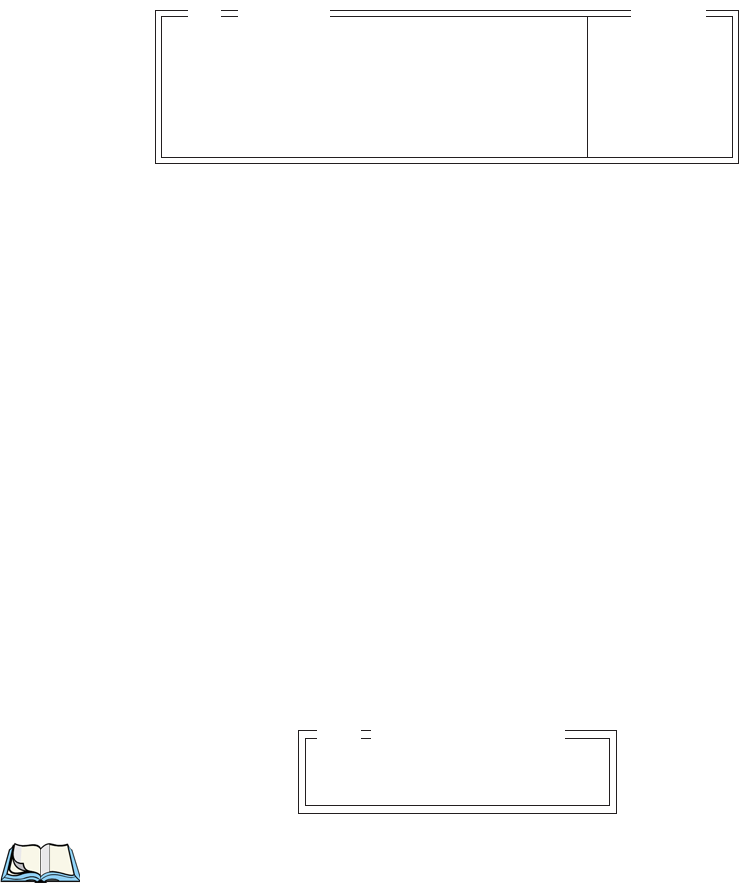
Chapter 6: Tekterm Application
Serial
210 Psion Teklogix 7535 Hand-Held Computer User Manual
6.18.1.6 Serial
Primary Port & Secondary Port
ANSI print commands (such as ‘MC’ or Media Copy) control the transfer of data to
and from the serial and console ports on the 7535. At the 7535, the value assigned at
the ‘Primary Port’ and ‘Secondary Port’ parameters determines which port the
ANSI print command will identify and use as primary and secondary. The allowable
options are: Any Available, Ist printer, 2nd printer, 3rd printer,
4th printer, 1st Serial, 2nd Serial, 3rd Serial, 4th Serial and
Disabled.
Async In
When this parameter is enabled (set to “Y”), the serial (async) port is ready to
receive input at all times.
Start/End
These parameters specify the “start” and “end” characters of input received from
the serial (async) port.
6.18.1.7 Host Char Set
The ‘Host Char Set’ menu allows you to specify a character set in the ‘Lower’ and
‘Upper’ character tables.
Note: When an 8-bit set is selected from the ‘Lower’ character set, the ‘Upper’
character set will change to the same value. The ‘Upper’ character set
cannot be altered until a non-8-bit value is assigned for the ‘Lower’
character set.
Primary Port Any Available see text
Secondary Port Any Available see text
Async In N Y/N
Start 0 0..255
End 0 0..255
05 Serial Range
Lower VT220 Fren Cdn.
Upper Arabic IR-127
Host Char Set
05

Psion Teklogix 7535 Hand-Held Computer User Manual 211
Chapter 6: Tekterm Application
Anchor View
To choose ‘Lower’ and ‘Upper character sets:
• Position the cursor on the ‘Lower’ or ‘Upper’ parameter, and press the
<RIGHT> or <LEFT> arrow key to display the character set options.
• Press <F4> to save your selection to memory.
Important: When a character sent from the host cannot be displayed, a
rectangular box is used as a substitute.
6.18.1.8 Anchor View
When enabled (set to “Y”), this parameter locks the display at a defined location on
the screen, preventing it from shifting when the cursor is moved. The “x origin” and
“y origin” coordinates specify where the screen origin, the upper left corner of the
screen, will be fixed.
x origin and y origin
The “x origin” parameter is used to specify the column to which the upper left
corner of the screen will be anchored. The “y origin” parameter is used to specify
the row coordinate to which the screen will be anchored.
x origin 1 1..24
y origin 1 1..80
Anchor Range
05
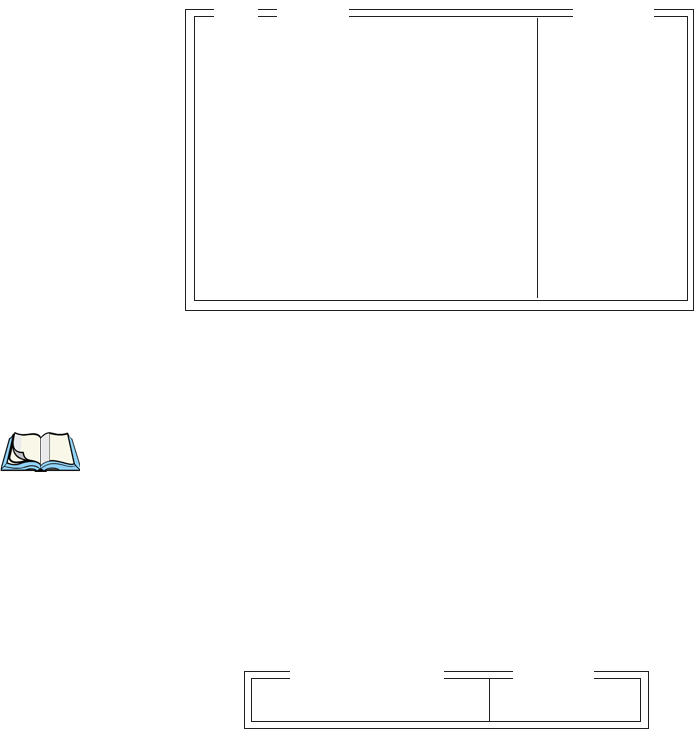
Chapter 6: Tekterm Application
TESS Settings
212 Psion Teklogix 7535 Hand-Held Computer User Manual
6.18.2 TESS Settings
Each session you create has its own “Settings” parameters. Additional TESS
information is documented in “TESS Emulation” on page 154.
Auto Term#
Note: “Auto Term#” is available when 802.IQv2 is assigned to the “Host
Conn” parameter (page 213) or when 802.IQv1 is enabled in the Radio
Menu (see “802.IQ v1” on page 179).
When this parameter is set to “Y”, a unique unit number is assigned for the current
TESS session. If “Auto Term#” is set to “Y”, any value assigned to the “Terminal #”
parameter is ignored.
Group
When “Auto Term#” is set to “Y”, the ‘Group’ parameter is used to identify the
group or pool of numbers from which an auto-address is chosen.
Auto Term # N»
Terminal # 1 see text
Host Conn » see text
Screen » see text
Characters » see text
Tests » see text
Features » see text
Scanner » see text
Fields » see text
Anchor View N» see text
Emulation » see text
TESS Range
04
Group 1 1-5
Range
Auto Term#
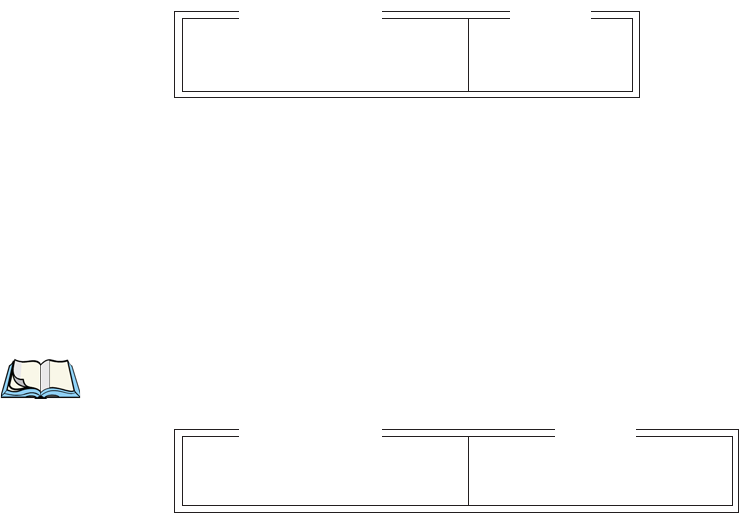
Psion Teklogix 7535 Hand-Held Computer User Manual 213
Chapter 6: Tekterm Application
Host Conn.
Terminal #
For every application session you create, the “Terminal #” assigned must be non-
zero and unique. This parameter defines the terminal number for the TESS session
and uniquely identifies all transmissions to and from the 7535.
Other applications running in the 7535, such as an ANSI session or another TESS
session must each have a different number. In addition, each Psion Teklogix 7535
using the radio link must have a unique number.
6.18.2.1 Host Conn.
Conn Type
The options for this a parameter vary depending on the type of application you are
running – ANSI or TESS.
For TESS applications, this parameter allows you to choose one of the following
types of connections: 802.IQv2, 9010t (TCP Direct), 2392/Telnet,
3274/Telnet and 5250/Telnet.
Settings
Note: The “Settings” sub-menu is not available when 802.IQv2 is selected as
the “Conn Type”
Host
This parameter is used to assign a host IP address using the format ###.###.###.###
Port
“Port” specifies the port number. By default, the port is assigned the value 9999.
Conn Type 802.IQv2 see text
Settings » see text
Range
Host Conn
Host see text
Port 9999 0-9999
Range
Settings
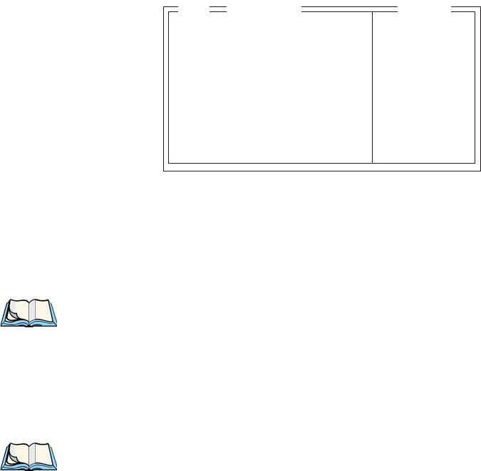
Chapter 6: Tekterm Application
Screen
214 Psion Teklogix 7535 Hand-Held Computer User Manual
6.18.2.2 Screen
# of Cols
This parameter defines the logical page width (in characters) used by the host
computer application. Emulator systems trim the host application screens to this
width. This page width cannot be smaller than the width of the 7535 display.
Display panning is used if the page is wider than the display.
Note: The value in this parameter must be an even number.
# of Rows
This parameter defines the logical page length (in lines) used by the host computer
application. Emulator systems trim the host application screens to this length. This
page length cannot be smaller than the length of the hand-held computer’s display.
Display panning is used if the page is longer than the display.
Note: The value in this parameter must be an even number.
Origin Scroll
When enabled (set to “Y”), the display window moves to the origin (upper-left
corner) after “LOCK-H” or “LOCK-B” messages.
Field Scroll
When enabled (set to “Y”), the display window moves to the left after entering a
new entry field.
# of Cols 80 20..132
# of Rows 24 4..100
Origin Scroll N Y/N
Field Scroll N Y/N
Pages Saved 16 1..16
App. Parameter 0 -1..79
Label F1-6 » see text
Colour Override N» see text
Screen
05 Range

Psion Teklogix 7535 Hand-Held Computer User Manual 215
Chapter 6: Tekterm Application
Screen
Pages Saved
This parameter determines the number of pages that can be stored and recalled at
the 7535. Storing frequently used page data at the 7535 reduces the need for the host
to retransmit complete page data over the radio link. Retransmitting data can reduce
the system response time. Increasing the number of saved pages decreases the
available memory for other functions.
App. Parameter
The “Application” parameter is sent to the host system as part of the response to
the TESS query command. Enter zero to disable this parameter.
Label F1-F6
Note: This menu uses string entry fields. For detailed information about com-
pleting this type of field, refer to “String Entry Parameters” on page 171.
Softkeys are function keys that have been programmed to perform specific actions
in your application. These keys are identified through softkey labels – reverse video
labels that are displayed at the bottom of the screen. These softkey labels can be
reconfigured using the menu attached to the “Label F1-F6” parameter.
To edit a label:
• Position the cursor in the appropriate function key field within the
Label menu, and type a new name – preferably one that describes
the corresponding key’s function.
Note: Although you can enter up to 8 characters for each softkey label, the text
will be shortened to better fit in the available space on your display.
F1
•
•
•
F6
Label F1-6
06
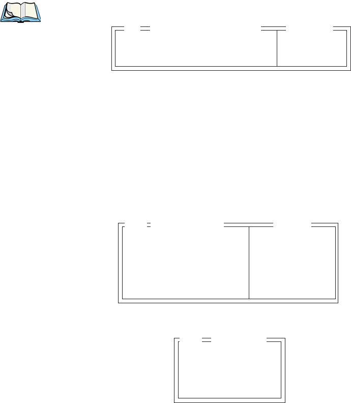
Chapter 6: Tekterm Application
Characters
216 Psion Teklogix 7535 Hand-Held Computer User Manual
Colour Override
Note: The menu is available only if your 7535 is equipped with a colour display.
Foreground And Background
When “Colour Override” is set to ‘Y’, the colours chosen in this menu are displayed
in the TESS sessions. These colour settings override the “Default Colours” set from
within the “View Manager” menu. Refer to “Default Colours” on page 193 for
details.
The allowable values are: Red, Green, Yellow, Blue, Magenta, Cyan, White
and Black.
6.18.2.3 Characters
Char Set
This menu contains all the character sets available with your Psion Teklogix
computer. In this menu, the “Y” or “N” is used to visually guide you to the selected
character set. For example, in the sample menu above, the “Y” next to IBM
indicates that a character set has been chosen from this group.
Foreground Black see text
Background White see text
06 Colour Override
Range
Char Set » see text
V Match Char 0 0..255
H Match Char 0 0..255
Fill Chr 46 0..255
Upper Case N Y/N
Range
Characters
05
ISO N »
IBM Y »
DEC N »
Misc. N »
06 Char Set

Psion Teklogix 7535 Hand-Held Computer User Manual 217
Chapter 6: Tekterm Application
Characters
To choose a character set:
• Position the cursor on the appropriate item – for example, ISO – and press
<F1> to display the character set options.
• To activate a character set, press the <RIGHT> or <LEFT> arrow key to set
it to “Y”.
Important: If you choose a Chinese character set from the ‘Misc.’ menu and
a character sent from the host cannot be displayed on the 7535
screen, a shaded box character is used as a substitute. Please
review “Default font” on page 226.
If you are using a Korean character set, a right arrow character is
used as a substitute.
V Match Chr
This parameter enables visible field matching and defines the character that identifies
visible field match data from the host. Field matching allows the host to pre-load
data into an entry field that is compared with the user’s input. The hand-held beeps if
the entered data does not match. Visible field matching means that the data to be
matched is displayed in the entry field.
Enter the decimal value for the ASCII character that will be used by the host to
identify visible match field data. Enter 0 (zero) to disable this feature.
Note: Another method of field matching is available directly through the
TESS data stream.
H Match Chr
This parameter enables hidden field matching and defines the character that identifies
hidden field match data from the host. Field matching allows the host to pre-load
data into an entry field that is compared with the user’s input. The 7535 beeps
if the entered data does not match. Hidden field matching means that the data to be
matched is not displayed in the entry field.
Enter the decimal value for the ASCII character that will be used by the host to
identify hidden match field data. Enter 0 (zero) to disable this feature.
Note: Another method of field matching is available directly through the
TESS data stream.

Chapter 6: Tekterm Application
Tests
218 Psion Teklogix 7535 Hand-Held Computer User Manual
Fill Chr
This parameter specifies the character that identifies empty entry fields. Enter
the ASCII decimal equivalent of this character. The most commonly used
characters are:
_ (underline) Enter 95
. (period) Enter 46
Note: 7535s in some systems may use the “space” character with the host using
reverse video attributes to mark entry fields.
Upper Case
When this parameter is enabled (set to “Y”), lowercase input is converted
to uppercase.
6.18.2.4 Tests
AutoRep Fn
This parameter determines which function key is sent to the host in auto reply mode.
The value represents the number of the function key – not the ASCII decimal
equivalent. After sending this key, the unit locks and waits for the host to unlock the
7535. To disable “AutoRep Fn”, set the “AutoRep T/O” parameter to zero.
AutoRep T/O
This parameter determines the time (in seconds) between the 7535 unlocking and
the next transmission of the function key specified by the above parameter.
A value of zero disables auto reply mode.
AutoRep Fn 7 0..63
AutoRep T/O 5 0..255
05 Tests Range

Psion Teklogix 7535 Hand-Held Computer User Manual 219
Chapter 6: Tekterm Application
Features
6.18.2.5 Features
Printer
This parameter enables and disables the pins in the serial port used for printers or
other external devices.
Binary print
When this parameter is enabled (set to “Y”), the page displayed on the 7535
computer is spooled as is, except for trailing white-space removal. When disabled
(set to “N”), each line of the page displayed on the hand-held is preceded by a
linefeed (LF) and followed by a carriage return (CR).
Queuing
This parameter enables and disables queuing mode (see “Queuing Mode” on
page 162). It also enables TESS procedures to be loaded into the 7535. This
parameter should be enabled if local procedures and the ability to switch between
hosts within a TESS session are required. Changes to this parameter take effect only
after the 7535 is reset.
Lcl Process – Save on Reset
The menu item “Local Process” has a sub-menu attached to it – “Save on Reset”.
When this parameter is enabled (set to “Y”), data stored in the 7535 is saved if the
unit is reset. Local procedures are defined on page 161.
Printer Y Y/N
Binary print N Y/N
Queuing Y Y/N
Lcl Process Y » see text
Send Mile N Y/N
Next X N Y/N
Kbd Locked N Y/N
Remap Passthru N Y/N
Disable Beep N Y/N
Serial » see text
05 Features Range
Chapter 6: Tekterm Application
Features
220 Psion Teklogix 7535 Hand-Held Computer User Manual
Send Mile
This parameter controls the sending of a milestone from the 7535 after a “hey_you”
command. Consult the Teklogix Screen Subsystem (TESS) User Manual for more
information on milestones.
Next X
This parameter enables and disables the next messages used in queuing mode.
Kbd Locked
This parameter allows you to lock (set to “Y”) or unlock (set to “N”) the keyboard
for all alphanumeric input in TESS. When the keyboard is locked, the function
keys, arrow keys and the <ENTER> key are still functional. The 7535 emits
an error beep if a character is rejected because the keyboard is locked. Changes to
this parameter take effect only after the unit is reset.
Remap Passthru
When this parameter is set to “Y”, passthru data is remapped from the host charset
to the port charset. (Normally passthru data is sent as is to the port without any
remapping.)
Disable Beep
Setting this parameter to “y” disables the beep generated by the ‘o’, ‘G’ and ‘#’
TESS commands. Keep in mind that Error and Scan beeps are not disabled.

Psion Teklogix 7535 Hand-Held Computer User Manual 221
Chapter 6: Tekterm Application
Features
Serial
Serial Port
TESS print commands control the transfer of data to and from the serial and printer
ports on the 7535. At the 7535 computer, the value assigned at the ‘Serial Port’
parameter ranks which port the TESS print command will identify and use as the
first to fourth port. The allowable options are: Any Available, 1st Serial,
2nd Serial, 3rd Serial, 4th Serial and Disabled.
Serial Out
This parameter enables serial port output fields.
Serial In
This parameter enables the serial port input fields. If enabled (set to “Y”), the TESS
application has exclusive use of the serial port. Acceptance of data in a SI field is
determined by the SI prefix and suffix.
SI mode
The possible values for this parameter are field (the default) and command. When
the SI mode is set to field, data received through the serial port is displayed in the
serial input fields. If you are using serial-input fields, make sure the “SI mode”
parameter is set to field.
When “SI mode” is set to command, data received by the serial port is transmitted as
Passthrough data to the host.
Note: “Command” mode is supported by SDKs but not by emulations.
Serial Port Any Available see text
Serial Out Y Y/N
Serial In N Y/N
SI mode see text
SI prefix 10 0..255
SI suffix 13 0..255
SI CRC N Y/N
SI Fkey 0 0..255
SO prefix 10 0..255
SO suffix 13 0..255
SO CRC N Y/N
06 Serial Range

Chapter 6: Tekterm Application
Features
222 Psion Teklogix 7535 Hand-Held Computer User Manual
SI prefix
This parameter determines the start-of-message character on serial input. Enter an
ASCII numeric equivalent from 0 to 255 to represent the start character. A value of
0 (zero) indicates no prefix.
SI suffix
This parameter determines the end-of-message character on serial input. Enter an
ASCII numeric equivalent from 0 to 255 to represent the end character. A value of
0 (zero) indicates no suffix.
SI CRC
This parameter enables or disables CRC validity check on serial input. When
enabled (set to “Y”), a packet is rejected if the CRC is not valid.
Also, when this parameter is enabled (set to “Y”), each time a DLE (^P=0x10)
character is encountered in the serial input, it is removed and the character
following it will be replaced with its 1’s complement.
SI Fkey
This parameter allows you to choose the function key you want appended to the
serial input. For example, entering a value of “1” appends <F1> to serial input. A
value of “0” (zero) disables this parameter; a suffix is not added.
Note: Data is transmitted as soon as the function key has been appended.
SO prefix
This parameter determines the start-of-message character on serial output. Enter an
ASCII numeric equivalent from 0 to 255 to represent the start character. A value of
“0” (zero) indicates no prefix.
SO suffix
This parameter determines the end-of-message character on serial output. Enter an
ASCII numeric equivalent from 0 to 255 to represent the end character. A value of
“0” (zero) indicates no suffix.

Psion Teklogix 7535 Hand-Held Computer User Manual 223
Chapter 6: Tekterm Application
Scanner
SO CRC
When this parameter is enabled (set to “Y”), a CRC16 value is appended to the
serial output message.
Also, when this parameter is enabled (set to “Y”), for each control character in
the serial output stream, a DLE is inserted to precede that character. The control
character is replaced with its 1’s complement.
6.18.2.6 Scanner
Cont Nxt Fld
This parameter only applies to string entry data. When enabled (set to “Y”), this
parameter allows bar codes that are longer than the field length to continue in the
next field.
If “ContNxtField” is disabled (set to “N”), OFF data will flow into the next field.
Append Enter
When enabled (set to “Y”), “Append Enter” causes an <ENTER> code to be
appended to the bar code. The <ENTER> code completes the entry of the bar code
and moves the cursor to the next field.
Append F0
When enabled (set to “Y”), this parameter causes an <F0> code to be appended to
the bar code. The <F0> code completes the entry of the bar code data in the field.
Cont Nxt Fld YY/N
Append Enter Y Y/N
Append F0 Y Y/N
Mixed AIAG N Y/N
Rjct if Alpha N Y/N
Beam Lockout N Y/N
Range
Scanner
05

Chapter 6: Tekterm Application
Fields
224 Psion Teklogix 7535 Hand-Held Computer User Manual
Mixed AIAG
When this parameter is enabled (set to “Y”), AIAG labels are always accepted and
processed – even if mixed with keyboard input. The AIAG label can replace the
partially entered keyboard data. If this parameter is disabled, AIAG labels are
rejected if field entry is in progress.
Rjct if Alpha
When the cursor is in a numeric field and “Rjct if Alpha” is enabled (set to “Y”),
bar codes containing alphabetic characters are rejected.
Beam Lockout
When enabled (set to “Y”), this parameter disallows scanner use when the current
session is in “LOCK-H” mode.
6.18.2.7 Fields
Field Order
This parameter determines the mode of cursor movement between fields. The next
field can be defined by location on the screen or by the assignment of field numbers.
When enabled (set to “Y”), the cursor moves according to field location. If disabled
(set to “N”), the cursor moves according to the numeric order of the fields.
Field Order YY/N
Enter To F0 Y Y/N
Enter On Arrow Y Y/N
Video » see text
All Fld Video Y Y/N
Default Font 16x30 see text
Entry Mode field see text
Open Fky Only N Y/N
Ign Bcode_fld N Y/N
Enh Edit Mode N Y/N
Valid Numerics +-%*/.,$ see text
Range
Fields
05

Psion Teklogix 7535 Hand-Held Computer User Manual 225
Chapter 6: Tekterm Application
Fields
Enter To F0
The <ENTER> key normally enters data into a field and moves the cursor to the
next field. However, some applications require that the <ENTER> key start a
transmission from the 7535. When enabled (set to “Y”), this parameter causes the
<ENTER> key to be interpreted as <F0> which starts a transmission.
Enter On Arr
When this parameter is enabled (set to “Y”), the arrow keys can be used to complete
data entry into a field.
Video
Blink
The value assigned to this parameter specifies the actual video attributes to be
assigned to fields created with the “Blink” TESS attribute – that is, “BLNK” (blink),
“ULIN” (underline), “REV” (reverse) or “NONE” (normal).
Bold
The value assigned to this parameter specifies the actual video attributes to be
assigned to fields created with the “Bold” TESS attribute – that is, “BLNK” (blink),
“ULIN” (underline), “REV” (reverse) or “NONE” (normal).
Reverse
The value assigned to the “Reverse” parameter specifies the actual video attributes
to be assigned to fields created with the “Reverse” TESS attribute – that is, “BLNK”
(blink), “ULIN” (underline), “REV” (reverse) or “NONE” (normal).
All Fld Video
Usually, the video attributes apply only to the text that is in an entry field. When this
parameter is enabled (set to “Y”), the entire field (including blanks) takes on the
video attributes. Some systems use this option to identify empty entry fields with
reverse video.
Blink BLNK see text
Bold ULIN see text
Reverse REV see text
Video Range
06
Chapter 6: Tekterm Application
Fields
226 Psion Teklogix 7535 Hand-Held Computer User Manual
Default font
This parameter determines the default font that appears when the memory is reset.
• Use the <RIGHT> or <LEFT> arrow key to scroll through the options.
Entry Mode
“Entry Mode” parameters allow you to select a data entry mode. The modes are:
insert, replace, field and fcursor. “TESS Edit Modes And Cursor
Movement” on page 156 describes these modes in detail.
Open Fky Only
When this parameter is enabled (set to “Y”), the screen is open for function keys
only, and the cursor is not positioned. When this parameter is disabled, the screen is
open for data entry, and the cursor is placed in the first field (if it exists).
Ign Bcode_fld
When this parameter is enabled (set to “Y”), fields that were defined as “bar code
only” accept data from the keyboard as well as the bar code reader. In effect, they
behave as data entry fields.
Enh Edit Mode
This mode provides extended (enhanced) functions to users of Psion Teklogix’ IBM
5250 terminal emulation. When this parameter is enabled (set to “Y”), the arrow
keys move the cursor anywhere on the screen, unrestricted by fixed or entry fields.
Certain 5250 emulation keys (e.g. Field Exit) that were originally available only
when “Enh Edit Mode” was set to “Y” are now active at all times in TESS
applications.
Refer to “IBM 5250 Emulation Keys” on page 155 for details about these keys.
Valid Numerics
This parameter is used to configure valid characters for numeric fields to a
maximum of 39 characters. Since this field is numeric, numbers 0 through 9 do not
need to be configured. The default values for this parameter are: + - % / . , $.
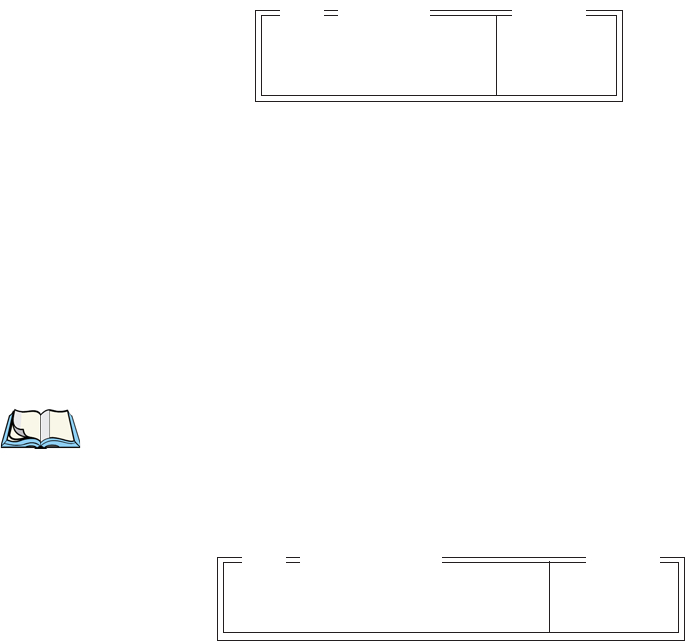
Psion Teklogix 7535 Hand-Held Computer User Manual 227
Chapter 6: Tekterm Application
Anchor View
6.18.2.8 Anchor View
When enabled (set to “Y”), this parameter locks the display at a defined location on
the screen, preventing it from shifting when the cursor is moved. The “x origin” and
“y origin” coordinates specify where the screen origin, the upper left corner of the
screen, will be fixed.
x origin and y origin
The “x origin” parameter is used to specify the column to which the upper left
corner of the screen will be anchored. The “y origin” parameter is used to specify
the row coordinate to which the screen will be anchored.
6.18.2.9 Emulation
Note: These parameters are only accessible when one of the following TESS
‘Host Conn’ options is selected: ‘2392/Telnet’, ‘3274/Telnet’ or
‘5250/Telnet’.
2392/Telnet Emulation
Send CR with FKEY
A function key press generates a string of text to be sent back to the host. If this
parameter is enabled, a carriage return is appended to the function key.
x origin 1 1..24
y origin 1 1..80
Anchor Range
05
Send CR with Fkey N Y/N
Features » see text
Emulation Range
05

Chapter 6: Tekterm Application
Emulation
228 Psion Teklogix 7535 Hand-Held Computer User Manual
Features – 2392/Telnet
Clear Entry Fields
When this parameter is set to ‘Y’, an empty entry field is created in place of an entry
field filled with spaces.
Note: This operation is only performed on screens received from the host. Data
sent to the host remains unaffected.
Passthru Printing
Setting this parameter to ‘Y’ allows the host to send data directly to the 7535 serial
port. This option is most commonly used for printing.
AIAG Character
This parameter is used to enter a decimal representation of the ASCII character code
of the AIAG character. A value of 0 (zero) disables this feature.
When a bar code data is scanned, the 7535 searches for AIAG fields on the current
page that can accept the bar code data. The application program distinguishes an
entry field as AIAG by preceding the field with this special mode character which
indicates the existence of AIAG fields.
Barcode Character
Barcode-input-only fields are special entry fields that only accept input from a bar
code reader. The application program identifies a barcode-input-only entry field by
preceding the field with a special character.
Clear Entry Fields N Y/N
Passthru Printing N Y/N
AIAG Character 0 0-255
Barcode Character 0 0-255
Serial IO Character 0 0-255
Fixed Field Ovrhd 5 0-80
Enable Alarm N Y/N
Command Region Up 0 0-24
Command Region Down 0 0-24
Command Region Left 0 0-80
Command Region Right 0 0-80
Features Range
06
Psion Teklogix 7535 Hand-Held Computer User Manual 229
Chapter 6: Tekterm Application
Emulation
This parameter is used to enter a decimal representation of the ASCII character code
of the barcode-input-only character. A value of 0 (zero) disables this feature.
Serial IO Character
Serial I/O fields are special entry and fixed fields that accept input from and output
to a serial port. The application program distinguishes this field as Serial I/O by
preceding the field with a special character. If this character precedes a fixed field,
the data will be sent to the 7535’s serial port. If it precedes an entry field, the field
accepts data from the 7535’s serial port.
This parameter allows you to enter a decimal representation of the ASCII character
code of this special character. A value of 0 (zero) disables this feature.
Fixed Field Ovrhd
This parameter defines the maximum number of characters allowed within two
adjacent, fixed fields that can be sent as a single field. For example, if two fields are
4 characters apart and this parameter is set to 5, these fields are joined into a single
field of data. The allowable range for this field is 0 to 80.
This feature affects fields with the “Normal” display attribute only.
Enable Alarm
If this parameter is set to ‘Y’, the 7535 emits a beep when the word ALARM
appears on the application screen, in the location specified by the “Command
Region” parameter.
Command Region Up & Down And Command Region Left & Right
The value assigned to the ‘Command Region Up’ and ‘Command Region Down’
parameters represent rows on the 7535 screen. The allowable values range from
0 to 24.
The value assigned to ‘Command Region Left’ and ‘Command Region Right’
parameters represent columns ont he 7535 screen. The allowable values range
from 0 to 80.
These four numbers represent the row and column addresses of the upper left corner
and the lower right corner of the command region. Currently, the only commands
supported in the command region are ALARM and FONT:

Chapter 6: Tekterm Application
Emulation
230 Psion Teklogix 7535 Hand-Held Computer User Manual
3274/Telnet Emulation
Fujitsu Host
If this parameter is set to ‘Y’, data is sent in Fujitsu format. Enabling ‘Fujitsu Host’
causes the standard IBM formatting codes (for start of field, setting buffers, etc.) to
be replaced by the codes used by Fujitsu host computers.
Intl EBCDIC
If this parameter is enabled (set to ‘Y’), the ‘international’ EBCDIC character set is
used, swapping the positions of the ! and ] characters.
Nulls in Fields
Setting this parameter to ‘Y’ allows ‘null’ characters – e.g., hyphens (-) or periods
(.) – to fill in empty entry fields.
IP for SysReq
When the system request key is pressed, a Telnet “Interrupt Process” command is
generated. The “Interrupt Process” command is sent to the host in place of the
standard mechanism used to send the system request key press to a host using
Telnet.
Fujitsu Host N Y/N
Intl EBCDIC N Y/N
Nulls in Fields N Y/N
IP for SysReq N Y/N
BRK for Attn N Y/N
LU Name Enabled N Y/N
LU Name see text
Features » see text
FKEY0-7 » see text
FKEY8-15 » see text
FKEY16-23 » see text
FKEY24-31 » see text
FKEY32-39 » see text
Emulation Range
05

Psion Teklogix 7535 Hand-Held Computer User Manual 231
Chapter 6: Tekterm Application
Emulation
BRK for Attn
When the attention key is pressed, a Telnet “Break” command is generated. This
command is sent to the host in place of the standard mechanism used to send the
attention key press to a host using Telnet.
LU Name Enabled
If enabled (set to ‘Y’), this parameter allows the 7535 to negotiate a specific device
name for itself.
LU Name
The value assigned in this field is used when the “LU Name Enabled” parameter
(see above) is set to ‘Y’. The current terminal number is appended to the name to
generate a unique device name (for example, LUA00001).
Features – 3274/Telnet
These parameters are identical to those described for 2392/Telnet. Refer to
"Features – 2392/Telnet" beginning on page 228.
Clear Entry Fields N Y/N
Passthru Printing N Y/N
AIAG Character 0 0-255
Barcode Character 0 0-255
Serial IO Character 0 0-255
Fixed Field Ovrhd 5 0-80
Enable Alarm N Y/N
Command Region Up 0 0-24
Command Region Down 0 0-24
Command Region Left 0 0-80
Command Region Right 0 0-80
Features Range
06

Chapter 6: Tekterm Application
Emulation
232 Psion Teklogix 7535 Hand-Held Computer User Manual
FKEY0-7, FKEY8-15, FKEY16-23, FKEY24-31 And FKEY32-39
The sub-menus attached to these parameters allow you to map the 7535 function
keys.
5250/Telnet Emulation
WEC (Write Error Code)
This parameter determines the type of WEC used. If set to “advisory”, a TESS
advisory message is generated when the host sends a WEC command to the 7535.
Otherwise, if set to “screen text”, the 7535 locks the keyboard and displays the error
message contained in the WEC command on the screen at the line specified by the
host. In this case, the 7535 must be unlocked manually using the function key
mapped to RESET.
FKEY0 ENTER
FKEY1 F1
FKEY2 F2
FKEY3 F3
FKEY4 F4
FKEY5 F5
FKEY6 F6
FKEY7 F7
06 FKEY0-7
WEC Advisory see text
Remap Underline to None see text
Intl EBCDIC N Y/N
Nulls in Fields Y Y/N
Term Type IBM-5251-11 see text
Virtual Dev Enable N Y/N
Virtual Dev Prefix see text
Features » see text
FKEY0-7 » see text
FKEY8-15 » see text
FKEY16-23 » see text
FKEY24-31 » see text
FKEY32-39 » see text
Emulation Range
05
Psion Teklogix 7535 Hand-Held Computer User Manual 233
Chapter 6: Tekterm Application
Emulation
Remap Underline To
This parameter allows you to remap the underline cursor to: blink, bold or
reverse.
Intl EBCDIC
If this parameter is enabled (set to ‘Y’), the ‘international’ EBCDIC character set is
used, swapping the positions of the ! and ] characters.
Nulls In Fields
Setting this parameter to ‘Y’ allows ‘null’ characters – e.g., hyphens (-) or periods
(.) – to fill in empty entry fields.
Term Type
The value assigned for this parameter – IBM-5555-001 or IBM-5251-11 – indicates
the type of terminal to report during the Telnet negotiations. It determines how the
AS/400 host treats the terminal. IBM-5251-11 is a standard 5250 terminal. IBM-
5555-001 is a Korean language terminal.
Virtual Dev Enabled
If enabled (set to ‘Y’), this parameter allows the 7535 to negotiate a specific device
name for itself.
Virtual Dev Prefix
The prefix assigned in this field is used when the “Virtual Dev Enabled” parameter
(see above) is set to ‘Y’. The current terminal number is appended to the prefix to
generate a unique device name. You can assign up to 10 upper-case alphanumeric
characters in this field.

Chapter 6: Tekterm Application
Emulation
234 Psion Teklogix 7535 Hand-Held Computer User Manual
Features – 5250/Telnet
These parameters are identical to those described for 2392/Telnet. Refer to
"Features – 2392/Telnet" beginning on page 228.
FKEY0-7, FKEY8-15, FKEY16-23, FKEY24-31 And FKEY32-39
The sub-menus attached to these parameters allow you to map the 7535 function
keys.
Clear Entry Fields N Y/N
Passthru Printing N Y/N
AIAG Character 0 0-255
Barcode Character 0 0-255
Serial IO Character 0 0-255
Fixed Field Ovrhd 5 0-80
Enable Alarm N Y/N
Command Region Up 0 0-24
Command Region Down 0 0-24
Command Region Left 0 0-80
Command Region Right 0 0-80
Features Range
06
FKEY0 ENTER
FKEY1 F1
FKEY2 F2
FKEY3 F3
FKEY4 F4
FKEY5 F5
FKEY6 F6
FKEY7 F7
06 FKEY0-7

Psion Teklogix 7535 Hand-Held Computer User Manual 235
Chapter 6: Tekterm Application
Ports– Tether And Console
6.19 Ports– Tether And Console
6.19.1 Tether And Console Port Peripheral Options
The “Tether Port” and “Console Port” options allow you to enable, disable and
specify the accessories attached to these ports. Both the Tether Port and the Console
Port have the same options. These are: Disabled, Serial, Console, Printer
and Scan-See.
To scroll through the options for each port:
• Press the <RIGHT> or <LEFT> arrow key.
These ports operate differently depending on the accessories selected.
• Disabled – indicates that the serial port is not being used.
• Serial – standard serial port.
• Console – used to connect another PC to the 7535. A communication
program is required so that communication can proceed between the 7535
and the PC.
• Printer – all TESS print operations are directed to the port. All ANSI media
copy operations to the “primary port” are directed to this port.
• Scan-See – TESS and ANSI accepts input from the Scan-See through the
Tether or Console port.
Tether Port Console
Settings 1 »
Console Port Disabled
Settings 2 »
Ports
03
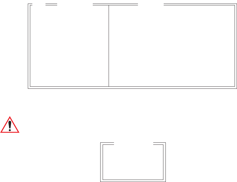
Chapter 6: Tekterm Application
Tether And Console Port Parameter Settings
236 Psion Teklogix 7535 Hand-Held Computer User Manual
6.19.2 Tether And Console Port Parameter Settings
The parameters for the “Tether Port” and “Console Port” are identical.
Character Set
These menus define the character set for the 7535 port.
Important: When a character sent from the host cannot be displayed, a
right arrow character is used as a substitute.
This menu contains all the character sets available with your Psion Teklogix
computer. In this menu, the “Y” or “N” are used to visually guide you to the selected
character set. For example, in the sample menu above, the “Y” next to IBM
indicates that a character set has been chosen from this group.
Character Set » see text
Baud 9600 see text for range of baud rates
Data Bits 8 6..8
Parity none none odd even mark space
Stop Bits 1 1, 1.5, 2
Flow Ctrl None None Software Hardware Both
Buffer 512 1..2048
Retries 3 1..100
Input Tmo 2 1..100
Output Tmo 5 1..100
Test Y Y/N
Settings Range
04
ISO N »
IBM Y »
DEC N »
Misc. N »
Char Set

Psion Teklogix 7535 Hand-Held Computer User Manual 237
Chapter 6: Tekterm Application
Tether And Console Port Parameter Settings
Choosing A Character Set
To choose a character set:
• Position the cursor on the appropriate item – for example, ISO – and press
<F1> to display the character set options.
• To activate a character set, press the <RIGHT> or <LEFT> arrow key to set
it to “Y”.
Important: If you choose a Chinese character set from the ‘Misc.’ menu and
a character sent from the host cannot be displayed on the screen,
a shaded box character is used as a substitute.
If you are using a Korean character set, a right arrow character is
used as a substitute.
Baud
This parameter determines the bit rate of the port. Allowable values include: 110
300 600 1200 2400 4800 9600 14.4kbps 19.2kbps 38.4kbps
56.0kbps 57.6kbps 115.2kbps 128.0kbps or 256.0kbps.
Data Bits
This parameter determines the number of bits for the data going through this port.
Possible values are: 6, 7, 8.
Parity
This parameter determines the type of parity checking used on the data going
through the port. The options are: none, odd, even, mark and space.
Stop Bits
This parameter specifies the number of stop bits – 1, 1.5, 2 – used for
asynchronous communication.
Flow Control
This parameter selects the type of flow control used in your hand-held computer.
The 7535 can perform Software or Hardware handshaking, or you can
choose Both to enable both of these options.
The function of each mode is as follows:
Enable: Used to input and output data.

Chapter 6: Tekterm Application
Tether And Console Port Parameter Settings
238 Psion Teklogix 7535 Hand-Held Computer User Manual
Supports XON/XOFF or no handshaking.
Print: Used to output data only. All input characters except XON and
XOFF are ignored.
Supports XON/XOFF or no handshaking.
Output: Used to output data only. All input characters are ignored.
Supports no handshaking.
Note: To enable the input and/or output, ‘serial in’ and/or ‘serial out’ must be
enabled in the TESS menu.
Buffer
The value assigned to this parameter determines the size of the serial buffer used by
the application for both input and output. The buffer controls the amount of data the
application can send to or receive from a serial device.
Retries
This parameter determines the number of times the 7535 attempts to transmit a byte
from the serial port. If the count specified in this parameter is exceeded, the
transmission fails.
Input Tmo
This parameter sets the time in tenths of a second that the 7535 waits before passing
received data to the TESS or ANSI tasks.
Output Tmo
The value assigned at this parameter determines the maximum number of
milliseconds that the application will wait for a ‘write’ sent to the port to succeed
before it is aborted. The ‘write’ may be one or several bytes in length.
Test
When this parameter is enabled (set to “Y”), data is output through the serial port to
make certain that it is operating appropriately.
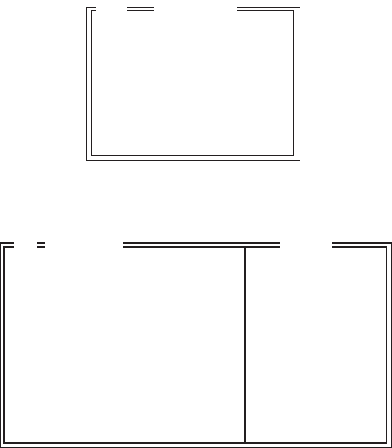
Psion Teklogix 7535 Hand-Held Computer User Manual 239
Chapter 6: Tekterm Application
Tether And Console Port Scan-See Parameters
6.19.3 Tether And Console Port Scan-See Parameters
When ‘Scan-See’ is specified as the peripheral for either the Tether or the Console
port, the parameters listed under the “Scan-See” sub-menu are used to tailor the
operation of this type of scanner. The other parameters listed in this menu –
“Character Set”, “Baud” and so on – are identical to those described beginning on
page 235.
6.19.3.1 Scan-See Sub-Menu – Mapping The Viewport
Character Set »
Baud 9600
Data Bits 8
Parity none
Stop Bits 1
Retries 3
Input Tmo 2
Scan-See »
Scan See
05
Anchor Line 1 0...1
Anchor Column 19 0...19
Follow Cursor Y Y/N
Line Offset 0 -25...25
Column Offset 0 -80...80
Wraparound N Y/N
Panning Y Y/N
Line Scrolling N Y/N
Brightness 3 0 to 5
Arrows Bright Bright Horz Vert
Version 2 0...2
XON/XOFF Y Y/N
05 Scan-See Range

Chapter 6: Tekterm Application
Scan-See Sub-Menu – Mapping The Viewport
240 Psion Teklogix 7535 Hand-Held Computer User Manual
The Scan-See display is mapped to a specific area on the 7535 screen – called
the viewport – and is continuously updated to reflect that portion of the screen. The
Scan-See viewport is defined as follows:
Anchor Line/Anchor Column
A location on the Scan-See display – the anchor – is chosen as a reference point.
Line Offset/Column Offset
A predefined displacement – the offset – is added to the location of the 7535 cursor
to create a point – the pivot. This pivot is mapped to the anchor , and whatever is
displayed in its vicinity is also displayed on the Scan-See.
For example:
• the anchor is chosen as (9,0) whereas “9” is the column and “0” is the line
(on the Scan-See display)
• the offset is chosen as (4,2)
• the cursor on the 7535 is currently located at (7,5)
• the pivot would thus be located at (7+4, 5+2) or (11,7)
• and so the area displayed on the Scan-See will be:
(11–9,7–0) to (11–9+9,7–0+1) or (2,7) to (11,8). 1
1These computations assume that “Wraparound” (described on page 242) is disabled
(set to “N”) and that “Follow Cursor” (described on page 242) is enabled (set to “Y”).
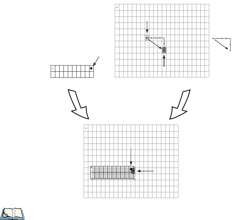
Psion Teklogix 7535 Hand-Held Computer User Manual 241
Chapter 6: Tekterm Application
Scan-See Sub-Menu – Mapping The Viewport
Note: To enter negative values, press the “-” (minus) key and then, type the
number you want to use.
The <LEFT> arrow key can also be used to decrement the value assigned
to the parameter. Each time the <LEFT> arrow is pressed, the number is
decremented by one. For example, to enter a value of “–5”, start from
zero and press the left arrow key five times.
(9,0)
anchor
Scan-See Display Terminal Display
superimposing
the anchor on the pivot
anchor
pivot
(11, 8)
(11, 7)
Scan-See Viewport
(2,7)
(11, 7)
offset
+4
+2
(4,2)
offset
+4
+2
terminal
cursor
pivot = + offset
(7,5)
terminal cursor
(0,0)
0123456789101112131415161718192021 . . .
(0,0)
0
1
2
3
4
5
6
7
8
9
10
11
. . .
0123456789101112131415161718192021 . . .
0
1
2
3
4
5
6
7
8
9
10
11
. . .
0123456789
0
1
(0,0)

Chapter 6: Tekterm Application
Scan-See Sub-Menu – Mapping The Viewport
242 Psion Teklogix 7535 Hand-Held Computer User Manual
Follow Cursor
When the “Follow Cursor” parameter is disabled (set to “N”), the cursor is always
assumed to be located at the origin. Using the previous example:
•the area displayed will be (4–9,2–0) to (4–9+9, 2–0+1), or, after clipping
values that are negative or higher than 80: (0,2) to (4,3).
Wraparound
When “Wraparound” is enabled (set to “Y”), the Scan-See display is treated as a
one-line by 20 column display, rather than 2 lines by 10 columns.
Panning
If “Panning” is disabled (set to “N”), the Scan-See viewport does not move when the
cursor moves one position to the right, and the pivot is still inside the Scan-See
display. However, the Scan-See display is updated to reflect the changes within that
viewport. If the pivot goes outside the viewport, or if the 7535 display changes
without the cursor being moved, the viewport is re-synchronized to coincide
the pivot with the anchor.
Line Scrolling
When “Line Scrolling” is enabled (set to “Y”), the Scan-See display is treated as
two separate one line by 10 column displays. The top line always displays the
previous value of the bottom line. In an application where the cursor skips from one
entry field to another, the field that the cursor just entered is displayed on the top
line, and the next field is displayed at the bottom.
Note: When this feature is enabled (set to “Y”), the “Panning” option should be
disabled to prevent updates to both lines after every keystroke
Brightness
The “Brightness” parameter controls the backlight brightness of the display. It only
has an effect on Model 7000 Scan-Sees – scanners equipped with LED (light
emitting diode) displays.
Psion Teklogix 7535 Hand-Held Computer User Manual 243
Chapter 6: Tekterm Application
Scan-See Sub-Menu – Mapping The Viewport
Arrows
The “Arrows” parameter assigns one of three possible functions to the two arrow
keys on the Scan-See keyboard:
Table 6.6 “Arrow” Parameter Options
Note: For “Horiz” and “Vert,” changing the offset will take affect only after the
7535 display has been updated.
Version
Scan-See units with serial numbers that read 1594120224 or higher contain
firmware that implements a different communication protocol with the 7535
than older units. The “Version” numbers represent the following unit versions:
Table 6.7 Scan-See Versions
Note: To interface the 7535 to the Scan-See units with older firmware
(serial number lower than 1594120224), set “Parity = space”;
all other parameters are identical to the newer firmware.
XON/XOFF
Important: IF YOU ARE USING TRANSCEIVERS WITH YOUR
SCAN-SEE, this parameter must be set to “Y”.
Value Function
“Bright”Arrow keys control Scan-See display brightness
“Horiz”Arrow keys control “Column Offset”
“Vert”Arrow keys control “Line Offset”
Value Scan-See Version
0•First LED version – up to serial number 1594080275; these are
encased in grey plastic.
1•Model 7000 LED units – versions after the serial number above;
these are also encased in grey plastic.
2•Metrologic 7000M LCD units; these are encased in grey plastic.
•Psion Teklogix 7000M LCD units; these are encased in black plastic.

Chapter 6: Tekterm Application
Scan-See Keyboard Mapping
244 Psion Teklogix 7535 Hand-Held Computer User Manual
When this parameter is set to “Y”, the XON and XOFF characters are not passed to
the TESS or ANSI tasks. A received XOFF character stops the serial port from
transmitting. A received XON character starts the serial port transmissions again.
6.19.3.2 Scan-See Keyboard Mapping
•Digits (0-9) are passed verbatim
•The CLR key forces a sign-on message and display refresh. This only
occurs when CLR is pressed and the CLR key on the display is pressed,
then released.
•The three F-keys are mapped to F1, F2 and F3, respectively.
•The ENT key is mapped to the carriage-return (‘\r’) character.
•The two arrow keys are handled locally, and control the brightness, and the
line and column offsets, as described on page 242.
•Bar-code data is stripped off any identifying headers (symbology, etc.)
and passed verbatim.
The Scan-See is capable of displaying only a subset of the default PC-8 ASCII
character set. Any characters that cannot be displayed are currently translated to ‘.’.
6.20 Network
Ctrl Panel »
802.IQv2 »
Network
03
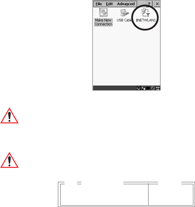
Psion Teklogix 7535 Hand-Held Computer User Manual 245
Chapter 6: Tekterm Application
Network Ctrl Panel Settings
6.20.1 Network Ctrl Panel Settings
This option displays a Windows CE screen where you can set up your radio, launch an
existing network connection or create a new connection. The radio icon
(NETWLAN1in the sample screen) in this window is used to configure the radio
installed in the 7535
Figure 6.11 Network Settings
Important: Follow the steps outlined in “Configuring An IEEE 802.11 Radio
Installed In The 7535” on page 18 for details about configuring
your radio.
6.20.2 802.IQ v2
Important: For setup information about 802.IQ v2, refer to the “9400 and
9450 Network Controllers User Manual” and/or the “9150
Wireless Gateway User Manual”.
Port 8888 see text
More Parameters » see text
802.IQ v2 Range
04
Chapter 6: Tekterm Application
802.IQ v2
246 Psion Teklogix 7535 Hand-Held Computer User Manual
Port
“Port” specifies the UDP port used by 802IQ v2. The default value is 8888. Keep in
mind that the value assigned here must match the value set at the network controller.
Note: When using 802.IQ v2, make certain that the 7535 “Net Mask” matches
the network controller net mask.
More Parameters
Important: The 802.IQ radio items listed in this menu are only available to
Psion Teklogix personnel.
Auto Radio Addr
If this parameter is set to “Y”, the 7535 requests an automatically assigned radio
address.
Note: If ‘Auto Radio Addr’ is enabled (set to “Y”), any value assigned to the
‘Radio Address’ parameter is ignored.
Radio Address
Important: “Radio Address” only takes effect when “Cellular” is
enabled (set to “Y”).
The value entered in the “Radio address” parameter is used to identify the 7535
hand-held over the radio link. A unique value from 1 to 3840 must be assigned for
each 7535.
Auto Radio Addr Y Y/N
Radio Address 0 1 to 3840
Initial RTT 100 500...5000
802.IQ v2 Parameters Range
05
Psion Teklogix 7535 Hand-Held Computer User Manual 247
Chapter 6: Tekterm Application
802.IQ v2
Initial RTT (Round Trip Time)
Round trip time is the elapsed time between a 7535 hand-held computer transmis-
sion and an access point acknowledgement. Each 7535 continuously adjusts the
acceptable round trip time, calculating the average elapsed time over a number of
transmissions. If an acknowledgement takes longer to receive than the average
round trip time calculated, the 7535 will resend the transmission.
Because 7535s cannot calculate an average round trip time without a number of
transmissions, a starting point or “Initial Round Trip Time” is required. The 7535
uses the time assigned to the “Initial RTT” parameter as a starting value for round
trip calculations. Once the 7535 begins transmitting and receiving data, this value
will be adjusted to reflect the actual average round trip time between transmissions
and acknowledgements.

Psion Teklogix 7535 Hand-Held Computer User Manual 249
PERIPHERAL DEVICES & ACCESSORIES7
7
7.1 External Bar Code Readers..........................251
7.1.1 PowerScan™ Standard, LR and XLR Bar Code Scanners ......251
7.1.2 Entering Data With The Bar Code Reader...............251
7.2 The 7535 Battery ...............................251
7.2.1 Lithium-Ion Battery Safety Precautions ................252
7.3 Important Charger Safety Instructions ....................253
7.4 Chargers ...................................254
7.5 Gang Charger.................................254
7.5.1 Installation ...............................255
7.5.2 Operator Controls ...........................255
7.5.3 Charge Indicators ...........................256
7.5.4 Charging Batteries ...........................256
7.5.5 Troubleshooting ............................257
7.5.5.1 Excessive Charge Duration ...................257
7.5.5.2 Indicator Flashing Red .....................257
7.5.5.3 Power LED Does Not Light Up.................257
7.5.5.4 Indicator Does Not Light When Battery Installed .......258
7.6 Combo Charger................................258
7.6.1 Installation ...............................258
7.6.2 Operator Controls ...........................259
7.6.3 Using the Combo Charger With The 7535...............259
7.6.4 Charging The Spare Battery ......................259
7.6.5 Charge Indicators ...........................260
7.6.6 Troubleshooting ............................260
7.7 Combo Dock .................................261
7.7.1 Installation ...............................261
7.7.2 Using The Combo Dock ........................261
7.7.3 Network Access ............................261
Chapter 7: Peripheral Devices & Accessories
250 Psion Teklogix 7535 Hand-Held Computer User Manual
7.7.4 Troubleshooting.............................262
7.8 Quad Dock ..................................262
7.8.1 Installation ...............................262
7.8.2 Indicators And Controls ........................263
7.8.3 Using The Quad Dock .........................263
7.8.4 Network Access.............................263
7.8.4.1 Network Addressing ......................263
7.8.5 Battery Charging ............................263
7.8.6 Troubleshooting.............................264
7.8.6.1 Network Link Unsuccessful ..................264
7.8.6.2 7535 LED Does Not Light When Docked...........264
7.9 Portable Docking Module (PDM) ......................264
7.10 Bluetooth Peripherals ............................268
7.11 The 7535 Picker Cradle ...........................268
7.11.1 Picker Cradle Mounting Recommendations .............269
7.11.1.1 Mounting Template......................269
7.11.2 Wiring Guidelines ...........................270
7.11.3 Using The Picker Cradle .......................270
7.11.4 Maintaining The Picker Cradle ....................270
7.11.5 Powered Cradle Installation In High Voltage Vehicles ........271
7.11.5.1 Extreme Wet Environments..................271
7.11.6 Powered Cradle Installation ......................272
7.11.6.1 Wiring Vehicle Power To The Cradle.............273
7.11.7 The Port Replicator ..........................274

Psion Teklogix 7535 Hand-Held Computer User Manual 251
Chapter 7: Peripheral Devices & Accessories
External Bar Code Readers
7.1 External Bar Code Readers
7.1.1 PowerScan™ Standard, LR and XLR Bar Code Scanners
Note: Refer to “SE1200 High Performance & Long Range Specs” on page 281
for detailed specifications.
The 7535 supports Psion Teklogix’ PowerScan™ industrial bar code scanner with
standard, long range and extra long range options.
To connect this scanner to the 7535, attach the device to the tether port at the upper-
right side of the 7535. Before using the bar code reader, you may need to change
some parameters. For details, review “Scanner Properties Setup” on page 118 and
“Bar Codes” on page 121.
7.1.2 Entering Data With The Bar Code Reader
Note: For helpful scanning tips, refer to “Scanning Techniques” on page 49.
When a label is scanned successfully, the 7535 will beep if configured appropriately
and the scan LED will flash. Occasionally, the bar code labels are poorly printed or
damaged and cannot be read properly. In this case, use the keyboard to enter data
from the label.
7.2 The 7535 Battery
Note: Battery specifications are detailed in“Lithium-Ion Battery Pack” on
page 288.
7535 Lithium-Ion batteries operate for a minimum of ten hours1 after a charge.
These batteries do not require conditioning. Typical battery life is 300 cycles or 3
years average use. A full charge is completed in 4 hours with a typical charge time
of 1.5 hours.
1Times are approximate and may vary depending on operating conditions.

Chapter 7: Peripheral Devices & Accessories
Lithium-Ion Battery Safety Precautions
252 Psion Teklogix 7535 Hand-Held Computer User Manual
7.2.1 Lithium-Ion Battery Safety Precautions
Important: It is critical that this safety information be reviewed and that all
warnings be strictly followed.
Warning: BATTERIES ARE CONSIDERED HAZARDOUS WASTE and
must be returned to Psion Teklogix for proper disposal. All used
batteries must be forwarded to one of the following offices:
Psion Teklogix Inc. Psion Teklogix Corp.
2100 Meadowvale Blvd. 1810 Airport Exchange Blvd.
Mississauga, Ontario Suite 500
Canada Erlanger, Kentucky
L5N 7J9 USA 41018
Psion Teklogix S.A.
La Duranne; 135 Rue Rene Descartes; BP 421000
13591 Aix-En-Provence
Cedex 3; France
Warning: TO PREVENT the battery from leaking acid, generating heat or
exploding, adhere to precautions listed below.
•The battery incorporates built-in safety devices. To ensure
their proper function, do not disassemble or alter any parts
of the battery.
•Do not short-circuit the battery by directly connecting any of the exposed
terminals with metal objects such as wire. Do not transport or store the
battery together with metal objects such as necklaces, hair pins, etc.
•Do not dispose of batteries in fire.
•Do not use or leave the battery near a heat source such as a fire
or heater.
•Do not immerse the battery in water.
•When charging, use the battery charger specifically designed for
the battery.
•Do not pierce, strike, throw or step on the battery.
•Do not directly solder the battery.
•Do not connect the battery to an electrical outlet, vehicle
cigarette lighter, etc.
•Do not put battery into a microwave oven or pressurized container.
•Do not use the battery in combination with primary batteries (such as
dry-cell batteries) or batteries of different capacities or brands.
•Immediately remove the battery from the device or battery charger
and stop use if the battery gives off an odor, generates heat, becomes
discoloured or deformed, or in any way appears abnormal during use.

Psion Teklogix 7535 Hand-Held Computer User Manual 253
Chapter 7: Peripheral Devices & Accessories
Important Charger Safety Instructions
•Do not continue charging the battery if it does not recharge within the
specified charge time.
•The battery may burst or ignite if the battery leaks. Always ensure that it
is away from any exposed flames.
•If leaking electrolyte sprays into your eyes, rinse them with clean
running water, and immediately seek medical attention.
•Do not store the battery in extremely high temperatures (e.g., a vehicle,
strong direct sunlight, etc.). This may cause the battery to overheat
or ignite, and it may also reduce the performance and service life of
the battery.
•Do not use in areas where static electricity is greater than what the
manufacturer guarantees.
•Keep batteries out of reach of children.
7.3 Important Charger Safety Instructions
•SAVE THESE INSTRUCTIONS – This manual contains important safety and
operating instructions for battery charger s.
•Before using the battery charger, read all instructions and cautionary
markings on (1) battery charger, (2) battery, and (3) product using battery.
•The mains power cord shall comply with national safety regulations of the country
where the equipment is to be sold.
•Use of an attachment not recommended or sold by the battery charger
manufacturer may result in fire, electric shock, or personal injury.
•To reduce risk of damage to the electric plug and cord when unplugging the
charger, pull the plug rather than the cord.
•Make sure the cord is positioned so that it is not stepped on, tripped over,
or otherwise subjected to damage or stress.
•Do not operate the charger with a damaged cord or plug.
Replace immediately.
•Do not operate the charger if it has received a sharp blow, been dropped, or other-
wise damaged in any way; it should be inspected by qualified service personnel.
•Do not disassemble the charger; it should be repaired by qualified service person-
nel. Incorrect reassembly may result in electric shock or fire.
•To reduce risk of electric shock, unplug the charger from the outlet before
attempting any maintenance or cleaning.
•An extension cord should not be used unless absolutely necessary. Use of an
improper extension cord could result in fire or electric shock.
If an extension cord must be used, make sure:
•The plug pins on the extension cord are the same number, size,
and shape as those on the charger.

Chapter 7: Peripheral Devices & Accessories
Chargers
254 Psion Teklogix 7535 Hand-Held Computer User Manual
•The extension cord is properly wired and in good electrical
condition and that the wire size is larger than 16 AWG.
•Do not expose the charger to rain or snow.
•Do not place batteries in the charger if they are cold from extended
exposure to a freezer or outside temperatures below 10°C (50°F). Allow them to
warm up to room temperature for at least two hours.
•Do not use the charger if, after an overnight charge, any of the batteries feel warmer
than the charger housing. The charger should be inspected by
qualified service personnel.
•Do not use the charger if any of the batteries or the charger get more than luke-
warm. The equipment should be inspected by qualified personnel.
7.4 Chargers
Note: Initially, new batteries that have been fully charged may indicate less than
100% charge. No special conditioning is required. The full capacity of the
battery will reach 100% after 5 cycles through the charger.
It can take from 1.5 to 4 hours to charge a battery. The 7535’s intelligent charging
system protects the battery from over-charging by terminating the charge process
when the battery is at maximum capacity.
Important: To preserve battery integrity, the charger will proceed with a
charge only when the battery temperature falls between 0˚ C and
39˚ C (32˚ F to 102˚ F). If the battery is too hot or cold, the battery
status LED flashes yellow and the charge is suspended.
7.5 Gang Charger
The gang charger is designed to charge up to six 7535 Lithium-Ion batteries at one
time. Your charger is shipped with the appropriate IEC mains power cord. If the
supplied power cord is incorrect for your country, contact Psion Teklogix for
assistance (see Appendix A: Support Services And Worldwide Offices).
Note: The gang charger is shipped with a user manual. It is critical that this
manual be reviewed for additional information and updates.
Psion Teklogix 7535 Hand-Held Computer User Manual 255
Chapter 7: Peripheral Devices & Accessories
Installation
7.5.1 Installation
The gang charger can be wall mounted using the wall mount kit – PN 1010039 – or
it can be operated on a flat surface. Install the charger in an area that is free from
excessive dirt, dust and contaminants. The ambient temperature must be in the range
0˚ C to 39˚ C (32˚ F to 102˚ F). The charger will not charge batteries outside
of this temperature range. For maximum performance, it is recommended that
the charger be operated at room temperature – a temperature range between
18˚ C to 25˚ C (64˚ F to 77˚ F).
The charger can consume up to 2A @ 120VAC or 1A @ 240VAC. Check to ensure
the mains circuit supplying the charger is adequate for this loading (especially if
several chargers are being powered from the same circuit).
After unpacking the unit:
•Visually check the charger for damage.
•Install the IEC power cord and apply power.
A green indicator in the lower-right lights to indicate power is present. All charge
indicators flash momentarily at powerup to indicate that the charger is ready for
operation.
If you choose to wall mount the charger, follow the instructions packaged with the
mounting bracket kit. Be sure to locate the charger in an area where there is no risk
of injury to persons walking in the vicinity.
7.5.2 Operator Controls
The gang charger does not have operator controls or a power switch.
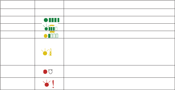
Chapter 7: Peripheral Devices & Accessories
Charge Indicators
256 Psion Teklogix 7535 Hand-Held Computer User Manual
7.5.3 Charge Indicators
Each battery charge slot is equipped with a tri-coloured LED to indicate the charge
status of the battery. When 7535 batteries are inserted in the charger, the colour and
behaviour of the LEDs associated with the charge wells in use indicate the status of
the charge.
Table 7.1 Gang Charger Indicators
7.5.4 Charging Batteries
•Install the battery with the battery contacts facing the charger. Slide the
battery between the guide rails until it lightly latches in place.
The LED directly below the slot in which a battery is inserted lights up immediately.
A solid yellow LED indicates that the battery is being charged. If the battery
temperature is outside 0˚ C to 39˚ C (32˚ F to 102˚ F), the LED flashes yellow until the
temperature is acceptable. A fully discharged battery will normally take between 1.5
and 4 hours to charge. When the battery charge reaches 75%, the indicator flashes
green. At full capacity, it turns solid green.
When the battery is fully charged, the charger stops applying power; the battery
cannot be overcharged if left in the charger slot. The 75% charge indicator is handy
if you need a quick recharge – it often occurs after less than an hour.
LED Behaviour Icon Charge Status
Off No battery detected in the slot.
Solid green Battery is fully charged.
Flashing green Battery is charged to 75% capacity.
Solid yellow Charge in progress.
Flashing
yellow
Battery temperature out of charge range between 0˚ C
to 39˚ C (32˚ F to 102˚ F). This icon indicates that the
charger is waiting to charge. Charging is attempted
every five minutes until the battery is within the appro-
priate temperature range.
Solid red Battery rejected (at insertion) or unable to complete
charge on battery
Flashing red Charging circuit problem. Refer to “Troubleshooting”
on page 257.
Psion Teklogix 7535 Hand-Held Computer User Manual 257
Chapter 7: Peripheral Devices & Accessories
Troubleshooting
7.5.5 Troubleshooting
7.5.5.1 Excessive Charge Duration
The charger is equipped with a recalibration function – a function that fully
discharges and then fully recharges the battery. This process is necessary to
recalibrate the battery capacity gauge internal to the battery. The charger attempts
recalibration when:
•the battery capacity is at less than 30%, and
•the battery has undergone more than 40 partial charge cycles since the last
full discharge.
A complete battery discharge takes between 1.5 and 4 hours to complete. When in
discharge mode, the LED indicator flashes yellow. The recalibration function
extends the charge time by up to 2 hours.
7.5.5.2 Indicator Flashing Red
If the indicator flashes red:
•Remove all batteries and disconnect the mains power cable.
•Wait at least 20 seconds, and then plug the cable in again.
If any of the charge slot LEDs continue to flash red, the charger is defective and
requires service. If all indicators are flashing red, there is a power supply problem
and the charger requires service.
7.5.5.3 Power LED Does Not Light Up
•Remove all batteries, and unplug the charger.
•Connect another device to the mains outlet to ensure there is power.
•Remove the IEC mains power cable from the charger, and check it for
damage.
•Reconnect the mains cable in the charger and mains outlet.
If the power LED still does not light up:
•Unplug the mains cable, and check the fuse at the rear of the charger.
If the fuse appears to be intact, the charger requires service.

Chapter 7: Peripheral Devices & Accessories
Indicator Does Not Light When Battery Installed
258 Psion Teklogix 7535 Hand-Held Computer User Manual
7.5.5.4 Indicator Does Not Light When Battery Installed
•Remove the battery, and clean the contacts on the battery and the
charge slot.
•Reinstall the battery, and check that it is fully seated in the slot.
•Inspect the charge slot contacts for damage (are they bent, flattened, twisted
or broken).
•Try inserting a battery that you know to be working in the charger slot.
•Reconnect the mains power cable, and check that the slot indicator flashes
at powerup.
7.6 Combo Charger
The 7535 combo charger is a desktop charger designed to charge the 7535 internal
battery along with a spare battery pack. The combo charger provides sufficient
power to operate and fast charge the 7535 internal battery, while recharging the
spare battery pack.
Note: The combo charger is shipped with a user manual. It is critical that this
manual be reviewed for additional information and updates.
7.6.1 Installation
Keep the combo charger away from excessive dirt, dust and contaminants. The
combo charger will not charge batteries outside an ambient temperature range of
0˚ C to 39˚ C (32˚ F to 102˚ F). It is recommended that this charger be operated at
room temperature – between 18˚ C and 25˚ C (64˚ F to 77˚ F) for maximum
performance.
After unpacking the unit:
•Visually inspect the charger for possible damage.
•Install the IEC power cord and apply power.
A green LED in the lower-right corner of the front panel lights to indicate that power
is present. The charge LED flashes momentarily at powerup. The charger is now
ready for operation.

Psion Teklogix 7535 Hand-Held Computer User Manual 259
Chapter 7: Peripheral Devices & Accessories
Operator Controls
7.6.2 Operator Controls
The combo charger has no operator controls or power switch.
7.6.3 Using the Combo Charger With The 7535
•Gently slide the 7535 into the cradle portion of the combo charger until
lightly latched. An icon is displayed indicating that the 7535 is properly
installed in the combo charger – .
The battery charge LED on the 7535 lights up indicating that the unit has external
power and battery charging may begin. It is safe to leave the 7535 in the combo
charger cradle while it is not in use – the battery will not be overcharged.
7.6.4 Charging The Spare Battery
•Install the battery with the latch facing towards the rear of the charger –
slide it between the guide rails until it lightly latches in place.
The LED for the slot lights up immediately. A solid yellow LED indicates the
battery is being charged. A flashing yellow LED indicates that the battery
temperature is outside the acceptable charge range – between 0˚ C and 39˚ C
(32˚ F to 102˚ F).
A fully discharged battery normally takes between 1.5 and 4 hours to charge. When
the battery capacity reaches 75%, the LED flashes green. When the battery is at full
capacity, the indicator turns solid green.
The combo charger stops applying power to the battery when it is fully charged –
there is no risk of overcharge if the battery remains in the charge slot. The 75%
charge indicator is handy if you need a quick recharge – a quick charge often takes
less than one hour.

Chapter 7: Peripheral Devices & Accessories
Charge Indicators
260 Psion Teklogix 7535 Hand-Held Computer User Manual
7.6.5 Charge Indicators
The spare battery charge slot has an associated tri-colour LED indicator on the
lower-right area of the front panel.
Table 7.2 Combo Charger Indicators
The combo charger supplies DC power to enable the 7535 internal fast charger.
Charge status is displayed on the 7535 charge LED – the lower-right LED. Refer to
“Charge LED” on page 43 for details.
Normally, it takes from 1.5 to 4.0 hours to fully charge the 7535 internal battery.
Note: Battery charging continues whether the 7535 is switched on or off.
7.6.6 Troubleshooting
The gang charger troubleshooting section also applies to the combo charger. Refer
to “Troubleshooting” on page 257, for helpful tips.
LED Behaviour Charge Status
Off No battery detected in the slot.
Solid green Battery is fully charged.
Flashing green Battery is charged to 75% capacity.
Solid yellow Charge in progress.
Flashing yellow
Battery temperature outside the charge range of between
0˚ C to 39˚ C (32˚ F to 102˚ F). Charging is attempted every
five minutes until the battery is within the appropriate tem-
perature range.
Solid red Battery rejected (at insertion) or unable to complete charge
on battery.
Flashing red Charging circuit problem. Refer to “Troubleshooting” on
page 257 for details.

Psion Teklogix 7535 Hand-Held Computer User Manual 261
Chapter 7: Peripheral Devices & Accessories
Combo Dock
7.7 Combo Dock
The combo dock is identical to the combo charger with one exception – the combo
dock is equipped with a 10/100 BaseT Ethernet interface. The charging information
in “Combo Charger” beginning on page 258 also applies to the combo dock.
7.7.1 Installation
Refer to the “Installation” guidelines for the combo charger beginning on page 258.
•Attach a CAT5 RJ45 network patch cable (shipped with the combo dock)
between your network and the RJ45 jack on the rear of the dock.
A green LED is illuminated next to the RJ45 connector when a valid network link is
established.
A user application needs to be loaded onto each 7535 that utilizes the combo dock
for communication. With the network connected and this application loaded, the
combo dock is ready for use.
7.7.2 Using The Combo Dock
•Gently slide the 7535 into the cradle portion of the combo dock until
lightly latched. The 7535 detects combo dock and displays the appropriate
icon – .
The battery charge LED (lower-right LED) on the 7535 lights up to show it has
external power and may start charging the battery.
Interaction with the 7535 while in the combo dock is a function of the user
application software used to communicate with the host network.
7.7.3 Network Access
The combo dock includes a dedicated USB to Ethernet converter. This USB
converter appears as a USB slave to the 7535 USB host controller. The 7535
automatically detects insertion into a combo dock and loads the appropriate drivers
to communicate with the USB/Ethernet converter.
See “Network Addressing” on page 263 for details about network addressing issues
with the combo dock.

Chapter 7: Peripheral Devices & Accessories
Troubleshooting
262 Psion Teklogix 7535 Hand-Held Computer User Manual
7.7.4 Troubleshooting
Troubleshooting issues for the combo dock are identical to those of the quad dock.
Refer to “Troubleshooting” on page 264 for helpful tips.
7.8 Quad Dock
Note: The quad dock is shipped with a user manual. It is critical that this man-
ual be reviewed for additional information and updates.
The Quad Dock permits each of four docked 7535 hand-helds to communicate with
a 10/100 BaseT Ethernet network at greater than 2Mbps. It also provides sufficient
power to operate and fast charge the batteries in the 7535s.
7.8.1 Installation
The quad dock should be located away from excessive dirt, dust and contaminants.
The ambient temperature must fall between 0˚ C to 39 ˚C (32˚ F to 102˚ F). The
7535 internal charger will not charge batteries outside of this temperature range. For
maximum performance, it is recommended that the quad dock be operated at room
temperature – from 18˚ C to 25˚ C (64˚ F to 77˚ F).
The quad dock can consume up to 3A @ 120VAC or 1.5A @ 240VAC. Ensure that
the mains circuit supplying the unit is adequate, especially if several docks are being
powered from the same circuit.
After unpacking the unit:
•Visually inspect the unit for any damage.
•Install the IEC power cord and apply power.
A green indicator in the lower-right corner of the front panel lights up to indicate
that power is present.
•Attach a CAT5 RJ45 network patch cable (supplied) between your network
and the RJ45 jack on the rear of the dock.
A green LED is illuminated next to the RJ45 connector when a valid network link is
established.
A user application must be loaded onto each 7535 that utilizes the quad dock for
communication. When the network is connected and this application is loaded, the
quad dock is ready for use.

Psion Teklogix 7535 Hand-Held Computer User Manual 263
Chapter 7: Peripheral Devices & Accessories
Indicators And Controls
7.8.2 Indicators And Controls
The quad dock has no user controls. It is equipped with a power indicator LED and
RJ45 link and traffic indicator LEDs. When a valid network link is established, a
green LED is illuminated next to the RJ45 connector.
7.8.3 Using The Quad Dock
•Gently slide the 7535 into the cradle portion of the quad dock until lightly
latched.
The 7535 detects that it is in a quad dock and displays the appropriate icon in the
taskbar – . The battery charge LED on the 7535 lights up to show it has external
power and may start charging the battery.
Interaction with the 7535 while in the quad dock is a function of the user application
software used to communicate with the host network.
7.8.4 Network Access
The quad dock includes a four port 10/100 Ethernet hub. Each of the four
downstream ports are connected to dedicated USB-to-Ethernet converters. These
USB converters appear as USB slaves to the 7535 USB host controller. The 7535
automatically detects insertion into a quad dock and loads the appropriate drivers to
communicate with the USB/Ethernet converters.
7.8.4.1 Network Addressing
Although the USB converters have fixed Ethernet MAC addresses, there is generally
no correlation between these addresses and a specific 7535 hand-held. The host
application uses standard TCP/IP protocol to name, locate and communicate with a
specific 7535 on the network.
If a link is established between a 7535 and a host, the application on the host and on
the 7535 must have a recovery mechanism in the event that the 7535 is removed
from the dock and the link is interrupted.
7.8.5 Battery Charging
The quad dock supplies DC power to enable the 7535 internal fast charger. Charge
status is displayed on the 7535 charge LED (see “Charge LED” on page 43). Battery
charging continues whether the 7535 is switched on or off.
Normally, it takes between 1.5 and 4 hours to fully charge the 7535 internal battery.

Chapter 7: Peripheral Devices & Accessories
Troubleshooting
264 Psion Teklogix 7535 Hand-Held Computer User Manual
7.8.6 Troubleshooting
The indicators, applications and drivers required to use and monitor the docking
station are installed on the 7535 – no indicators or applications are present on the
docking station itself.
7.8.6.1 Network Link Unsuccessful
If a network link fails, the 7535 application alerts the operator that the link was
unsuccessful.
7.8.6.2 7535 LED Does Not Light When Docked
•Check that the quad dock has power – is the Power LED on the quad
dock illuminated?
•Try inserting the 7535 in another slot in the quad dock.
•Check for dirt or contamination on the docking contacts at the bottom of the
7535. Wipe the contacts with a damp cloth if necessary.
•Check the pogo pins inside the dock cradle for dirt. Gently wipe with a
damp cloth if they appear to be dirty or discoloured.
•Check that the pogo pins are not bent or damaged.
•Remove and reinsert the 7535 in the cradle, and check that the latch is
holding the unit in place (the pogo pins must be compressed for proper
contact).
•Make certain that the battery installed in the 7535 is defective.
7.9 Portable Docking Module (PDM)
Warning: The mains power cord for the DC adapter shall comply with
national safety regulations of the country where the equipment
is to be sold.
The Portable Docking Module (PDM) clips onto the base of the 7535 and is most
often used to charge the 7535 battery when a desktop charger is not convenient. The
PDM also offers additional communication ports, making it useful for upgrading
software in the 7535 from a USB-equipped laptop computer. Figure 7.2 on page 267
illustrates the connectors on the PDM.

Psion Teklogix 7535 Hand-Held Computer User Manual 265
Chapter 7: Peripheral Devices & Accessories
Portable Docking Module (PDM)
•Align the pins on the PDM with the connectors on the base of the 7535.
•Gently snap the PDM into place on the base of the unit. Figure 7.1 on
page 266 provides a visual representation of how to secure the PDM.
Note: The latching mechanism on the PDM is designed for quick installation
and release. It is not meant for heavy duty use.
Psion Teklogix recommends using a powered cradle or combo charger in
harsh environments.
BEFORE DETACHING THE PDM FROM THE 7535, it is critical that you
carry out the following instructions:
•Unplug any external USB devices (mouse, etc.) from the PDM, or
•Turn off the 7535 hand-held before removing the PDM.
Warning: USB devices that are left attached to a PDM at the time that the
PDM is detached from the hand-held can be irreparably damaged
(burned out).
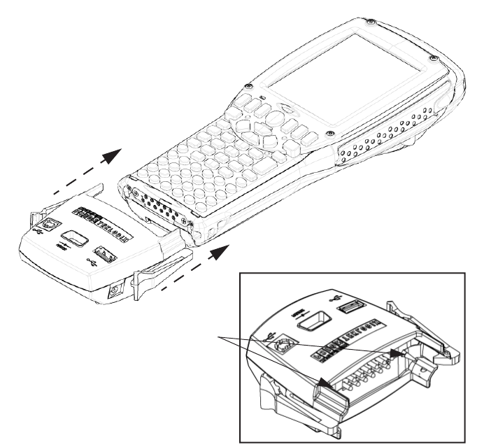
Chapter 7: Peripheral Devices & Accessories
Portable Docking Module (PDM)
266 Psion Teklogix 7535 Hand-Held Computer User Manual
Figure 7.1 Attaching The PDM To The Base Of The 7535
Align the guide pins on the PDM with the
slots on the base of the 7535, and
Guide Pins
gently snap the PDM onto the hand-held.
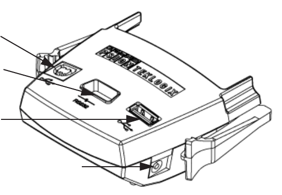
Psion Teklogix 7535 Hand-Held Computer User Manual 267
Chapter 7: Peripheral Devices & Accessories
Portable Docking Module (PDM)
Figure 7.2 PDM Ports And Connectors
The interfaces available on the PDM are as follows:
•DC power jack (15VDC @ 2.5A)
•Type A USB host port (for connection to USB devices such as a mouse,
keyboard, printer, etc.)
•Type B USB device port (for connection to a USB host such as a PC)
•RS232D DE9 serial port (for connection to a PC COM port or a serial
device such as a printer)
The standard Psion Teklogix PDM kit (PN HU4001) includes the necessary DC
power supply, USB cables and RS232D 9-pin cable.
A cigarette lighter adaptor (PN HU3012) is also available to connect the PDM to a
12 VDC vehicle’s power. Use only the recommended adaptor with the PDM – it
includes transient suppressors that protect your 7535 from damage.
The PDM contains reverse polarity and over voltage protection. If the DC power
jack is wired backwards or exceeds 20VDC, the PDM shuts down to protect the
7535, the PDM and the power supply from damage. Psion Teklogix does not
recommend substituting the DC power supply provided with your PDM.
The DC power supplied by the PDM is sufficient to operate the 7535 and fast charge
its internal battery at the same time. The 7535 can run from a PDM without a battery
installed.
Type B USB Device
RS232 Serial Port
Type A USB Host
15 VDC Power Jack
Chapter 7: Peripheral Devices & Accessories
Bluetooth Peripherals
268 Psion Teklogix 7535 Hand-Held Computer User Manual
7.10 Bluetooth Peripherals
If the 7535 is equipped with a Bluetooth radio, it is possible to communicate with a
variety of Bluetooth peripherals, including GSM/GPRS handsets, scanners, printers,
and so on. The range of the Bluetooth radio in the 7535 is limited to approximately
2 meters.
Psion Teklogix provides built-in support for the Bluetooth peripherals listed below.
•GSM/GPRS tri-band universal handset
•Bluetooth printer
Keep in mind that Bluetooth and IEEE 802.11b radios both operate in the 2.4GHz
band. Although the 7535 includes features to minimize interference, performance of
the system will not be optimal if you use both radios simultaneously. Typically,
when both radios operate in the 7535 at the same time, they cannot transmit
simultaneously – this has a negative impact on overall system throughput. To
minimize the impact on the backbone 802.11b network, Psion Teklogix
recommends using Bluetooth peripherals that have low transaction rates (such as
printers and scanners).
Bluetooth peripherals are configured using the Bluetooth control panel applet. Refer
to “Bluetooth Setup” on page 106 for information about setting up your Bluetooth
devices for communication. In addition, review the manual shipped with your
Bluetooth device to determine the method used to associate with the 7535 host.
7.11 The 7535 Picker Cradle
The 7535 picker cradle is a highly ruggedized, single station dock. Although it
provides quick insertion and removal, the cradle holds the 7535 securely even when
operated in high vibration environments (such as vehicles not equipped with
suspensions).
The7535 base picker cradle can be outfitted with two options – a power module and
a port replicator. Psion Teklogix also supplies a range of standard mounts for the
hand-held picker cradles, and the 7535 picker cradle is compatible with all of them.

Psion Teklogix 7535 Hand-Held Computer User Manual 269
Chapter 7: Peripheral Devices & Accessories
Picker Cradle Mounting Recommendations
7.11.1 Picker Cradle Mounting Recommendations
Warning: Before mounting a picker cradle in a vehicle, there are a number
of operator safety issues that require careful attention. An improp-
erly mounted cradle may result in one or more of the following:
operator injury, operator visibility obstruction, operator distraction
and/or poor ease of egress for the operator. Psion Teklogix strongly
recommends that you seek professional mounting advice from the
vehicle manufacturer.
Cable routing within a vehicle cab also requires careful consider-
ation, especially for separately tethered scanners and other devices
with loose cables. If you are unable to obtain suitable advice,
contact Psion Teklogix for assistance (see Appendix A: Support
Services And Worldwide Offices). Note also that for better protec-
tion, the equipment should be mounted inside the vehicle roll cage.
Pedestal mounts are recommended for all fixed mount locations because they offer
optimal operator access. In addition, for safety reasons, only pedestal mounts with
fully locking joints should be used in vehicles. Always adjust the pedestal for the
optimum viewing angle, and securely tighten the hex and wing screws.
The most effective way to mount the picker cradle is to use the four #8-32 threaded
inserts on the rear of the unit. Bolts must not extend more than 10mm (3/8") into the
cradle.
To accommodate the service loop of the connector cable, leave a 4" clearance at the
bottom of the cradle. Leave a 7" (minimum) clearance at the top of the cradle to
allow easy removal of the hand-held. Also remember to leave at least a 3" clearance
at the sides of the cradle to allow activation of the release knobs. Refer to the
detailed assembly instructions that are packaged with the cradle when selecting a
mounting location.
7.11.1.1 Mounting Template
The picker cradle is shipped with detailed mounting instructions including a drill
template.
Chapter 7: Peripheral Devices & Accessories
Wiring Guidelines
270 Psion Teklogix 7535 Hand-Held Computer User Manual
7.11.2 Wiring Guidelines
Before installing the cables between the cradle and other devices, consider
the following:
•Ensure that drilling holes will not damage the vehicle or its wiring.
•Protect cable runs from pinching, overheating and physical damage.
•Use grommets to protect cables that pass through metal.
•Use plastic straps and tie-downs to secure cables and connectors in their
desired location, away from areas where they may get snagged or pulled.
•Keep cables away from heat sources, grease, battery acid and other
potential hazards.
•Keep cables away from control pedals and other moving parts that may
damage the cables or interfere with the operation of the vehicle.
7.11.3 Using The Picker Cradle
If your 7535 is equipped with a shoulder strap or cover, these accessories need to be
removed before installing the unit in a picker cradle. There is no need to remove
handstraps, pistol grips or tethered devices from the unit.
•Slide the 7535 into the cradle, and press firmly downward until it locks into
place. On a vehicle, it’s a good idea to pull up on the 7535 to be certain that
it is secure.
•To remove the 7535, press firmly on one of the knobs on either side of the
cradle until it releases. You do not need to press both knobs.
7.11.4 Maintaining The Picker Cradle
Two latches in the cradle hold the 7535 firmly in place. Although these latches are
designed for at least 80,000 cycles, they will wear over time and will no longer lock
the 7535 securely in the cradle. For replacement parts and instructions contact Psion
Teklogix (see Appendix A: Support Services And Worldwide Offices). Partial
disassembly is required.

Psion Teklogix 7535 Hand-Held Computer User Manual 271
Chapter 7: Peripheral Devices & Accessories
Powered Cradle Installation In High Voltage Vehicles
7.11.5 Powered Cradle Installation In High Voltage Vehicles
Warning: Voltages exceeding 60VDC are considered hazardous. For powered
cradle installations on vehicles with batteries above this voltage,
ensure the powered cradle power connector is mounted in a dry
location on the vehicle, or that the connector is insulated with an
appropriate waterproof material after installation. The connector
must also be installed out of the vehicle operator’s reach. Exposing
an accessible power connector to water or other liquids could create
a hazardous situation resulting in serious injury or death.
Installation of powered cradles in vehicles that operate above 60VDC require
special consideration.
Due to the hazardous voltages present on these vehicles, it is necessary to ensure
that the powered cradle power supply cable connector is not accessible to the
vehicle operator, and does not get exposed to water or other liquids. This can be
accomplished in one of the following ways:
•Ensure the power connector is installed in a dry location on the vehicle,
away from the vehicle operator’s reach (perhaps under a vehicle dash or in a
sealed housing).
•Cover the power connector with a waterproof heat shrink material (see
“Extreme Wet Environments” note below for additional details).
•Wrap the connector securely with a waterproof electrical tape in an area out
of the vehicle operators reach.
All other installation requirements outlined in this document should also be
followed for High Voltage vehicles to insure safe installation and operation of the
powered cradle.
7.11.5.1 Extreme Wet Environments
For extreme wet environments, or environments where it is difficult to restrict
vehicle operator access to the power connector, Psion Teklogix offers a waterproof
heat shrink kit (PN 1030022). The kit contains 3 pieces of waterproof, high shrink
ratio heat shrink tubing which can be used to encapsulate the entire connector
assembly. If using this kit, please ensure that you order sufficient material to cover
installation and service, remembering that heat shrink is one-time use, and must be
replaced if it is removed from the connector for any reason.

Chapter 7: Peripheral Devices & Accessories
Powered Cradle Installation
272 Psion Teklogix 7535 Hand-Held Computer User Manual
7.11.6 Powered Cradle Installation
The powered cradle option is designed to allow the 7535 to be powered by a vehicle
battery. The battery installed in the 7535 is also recharged by the vehicle battery.
This option accepts DC power sources over the range 12V to 80V.
The 7535 picker cradle can be ordered with the powered cradle option installed, or it
can be retrofitted later at an authorized Psion Teklogix service depot. Service offices
are listed in Appendix A: Support Services And Worldwide Offices.
The 7535 charging LED (see Section 3.6.1.1 on page 43) indicates that external
power is available, and it also indicates the charging status of the internal battery.
Warning: Applying a voltage above 90VDC or reversing polarity may result
in permanent damage to the cradle power option and will void the
product warranty.
Warning: TO AVOID ELECTRIC SHOCK when the powered cradle option
is installed, always ensure that the rear panel ground lug on the
picker cradle is connected to the vehicle chassis. Failure to do this
could result in serious injury or death.
The metal chassis of the picker cradle must be connected directly to the chassis of
the vehicle. A safety ground lug (clearly labelled on the rear of the cradle chassis) is
provided for this purpose. The grounding strap must connect from the ground stud
on the picker cradle to a solid, reliable contact point on the main portion of the
vehicle chassis. It must not be connected to battery negative or a terminal block.
This grounding strap ensures that if there is a fault in the vehicle wiring or in the
picker cradle power module, the picker cradle cannot be at a hazardous voltage with
respect to the vehicle chassis.
Connection between the picker cradle ground lug and the vehicle chassis should be
done with a 16 gauge ground strap (ground wire). Connect the ground strap to the
picker cradle utilizing the ground lug hardware supplied with the picker cradle and a
#10 heavy duty wire crimp ring terminal. Torque the ground lug hardware to 23.0
+/- 2.0 in-lbs. Connect the other end of the ground strap to a solid, reliable point on
the main portion of the vehicle chassis, ensuring a solid electrical connection.
As with other vehicle cables, the routing of the ground strap should be carefully
considered to ensure it does not pose a hazard to the operator or the safe operation of
the vehicle. If necessary, secure the ground strap with cable ties or some other
mechanical means to prevent loops or loose lengths of wire that could catch on
stationary items when the vehicle is in motion.
Psion Teklogix 7535 Hand-Held Computer User Manual 273
Chapter 7: Peripheral Devices & Accessories
Wiring Vehicle Power To The Cradle
7.11.6.1 Wiring Vehicle Power To The Cradle
A 1.8 meter (6 foot) extension power cable (PN 13985) is supplied with your power
cradle. This cable should be wired to a filtered, fused (maximum 10A) accessory
supply on the vehicle. The power cradle draws no more than 8A (less if the
accessory supply is greater than 12V). Any additional wiring, connectors or
disconnects used should be rated for at least 10A.
The red lead of the power cable attaches to the positive vehicle supply. The black
lead connects to the negative supply – this should be connected to a proper terminal
block and not to the vehicle body. The power cradle is fully isolated and can be used
with both negative and positive chassis vehicles.
You may have the option of connecting power before or after the ‘key’ switch. It is
preferable to wire the power cradle after the key switch – that is, it cannot be turned
on without the key on. However, if the operator switches the key off repeatedly for
long periods during a shift, it may make more sense to wire the cradle before the
switch.
Keep in mind that the 7535 will continue to operate with or without vehicle power
as long as its battery has sufficient charge.
If an unfused power source must be used, a fuse assembly (PN 19440) must be
added to the extension power cable (the fuse and instructions are supplied with the
cable). Use only a 10A slow blow UL approved fuse in the fuse assembly.

Chapter 7: Peripheral Devices & Accessories
The Port Replicator
274 Psion Teklogix 7535 Hand-Held Computer User Manual
7.11.7 The Port Replicator
The port replicator is an optional accessory that allows tethered devices (e.g.,
scanners) as well as mounted peripherals (e.g., bar code printers or weigh scales) to
be attached to the picker cradle. The replicator can be used with or without the
cradle power option.
The functionality of the 7535 tether port is duplicated on the port replicator. In
addition to the tether port, the replicator is equipped with a standard 9 pin RS232D
serial interface. This interface is typically used for fixed peripherals such as printers.
Your serial device likely includes a suitable cable connector for this port.
Note: The 7535 picker cradle can be ordered with the port replicator option
installed, or it can be retrofitted later by an authorized Psion Teklogix
service depot. Service offices are listed in Appendix A: Support Services
And Worldwide Offices.

Psion Teklogix 7535 Hand-Held Computer User Manual 275
SPECIFICATIONS 8
8
8.1 7535 Hand-Held Computer Specifications ..................277
8.2 Radio Specifications .............................279
8.3 Bar Code Scanning ..............................279
8.3.1 Internal Scanners............................279
8.3.2 Internal Scanner Port..........................280
8.3.3 External Scanners ...........................280
8.4 Internal Scanner Specifications........................281
8.4.1 SE1200 High Performance & Long Range Specs ...........281
8.4.2 SE1200 Advanced Long Range & SE2223 PDF Specs ........282
8.4.3 Decode Zones .............................284
8.5 External Scanner Specifications .......................284
8.5.1 PowerScan™ LR and XLR Industrial Scanner Specs .........284
8.5.2 PowerScan™ Standard Range Scanner Specs.............287
8.6 Lithium-Ion Battery Pack ..........................288

Psion Teklogix 7535 Hand-Held Computer User Manual 277
Chapter 8: Specifications
7535 Hand-Held Computer Specifications
Note: Performance specifications are nominal and subject to change
without notice.
8.1 7535 Hand-Held Computer Specifications
Size•4" (102mm) width x 2.5" (62.5mm) depth x 9.6" (244mm) length
•Keypad area: 3" (75.5mm) width x 1.4" (36mm) depth
Weight
With battery 21.7 oz (700g)
With pistol grip add 4.3 oz (125g)
Operating System
Microsoft® Windows® CE.net Version 4.x
Processor And Memory
•400 MHz XScale PXA255 Processor
•RAM: 64MB SDRAM (Future option 128MB)
•Flash ROM: 32MB FLASH
Power
•7.2V @ 1800mAh Li-ion rechargeable battery.
•Intelligent fast charge.
•10 hour battery operation (5 scans, transmit & receive/min).
•Built-in gas gauge & performance monitor.
•Quick swap battery packs.
•Built-in fast charger (1.75 hour typical recharge).
•Self-guiding & latching battery pack design.
•System backup (10 minutes) during battery swap.
•1 week real-time clock backup.
Chapter 8: Specifications
7535 Hand-Held Computer Specifications
278 Psion Teklogix 7535 Hand-Held Computer User Manual
Communication
Ports Tether port (optional) with:
- one RS232 serial port (decoded scanner,
printer)
undecoded scanner port
USB host port, power out
- Docking station port with:
one RS232 serial port including diagnostics
USB device port, USB host port, power in/out
Environmental
Guaranteed Operating 32°F to 122°F (0°C to +50°C)
Temperature Range Short exposure to temperatures outside this range
may cause the 7535 monochrome screen to
become very dark or light temporarily.
Long exposure to temperatures below -40˚C (-
40˚F) may damage the screen. Prolonged expo-
sure to temperatures above +60˚C (+140˚F) will
damage the main battery and temperatures above
+70˚C (+158˚F) may damage the unit.
Storage Temperature -13°F to 140°F (-25°C to +60°C)
Rain And Dust Resistance IEC 529, classification IP54.
Humidity 5% - 95% RH non-condensing
Drop Durability Multiple 5 ft. (1.5m) drops to polished
concrete.
Cradle shock: 30g in each axis.
Cradle vibration: 1.5g RMS PSD (4Hz-500Hz).
Approvals
Safety UL 1950, CSA C22.2 No950, LVD EN60950
EMC FCC Part 15 Class B, EMC Directive Class B
Laser IEC 825-1 Class 2 (EN60825-1), 21CFR1040
Class II
Psion Teklogix 7530 Hand-Held Computer User Manual279
Chapter 8: Specifications
Radio Specifications
8.2 Radio Specifications
- RADIO PERFORMANCE SPECIFICATIONS
435-470 MHz
Frequency ControlSynthesized
Channel Spacing12.5
Mode of OperationSimplex or Half Duplex
Regulated Supply Voltage+5 VDC +/- 5%
Operating Temperature-30 to +60 Celsius Degree, -22 to +140 Farenheit Degrees
Maximum Dimensions:LxWxT = 7.19cm X 5.56cm X 1.70cm, 2.83” x 2.19” x 0.64”
Weight:2.3 oz. (65 g)
FCC Compliance:Yes
15.2RECEIVER
Bandwidth16 Mhz (20 MHz)
Frequency Stability+/- 1.5 ppm
Sensitivity - 12 dB SINAD0.45 uV
RF Input Impedance50 ohms
Selectivity-70 dB
Spurious and Image Rejection-60 dB (12.5 kHz), -70 dB (20/25 kHz)
Intermodulation-70 dB
FM Hum and Noise-40 dB (12.5 kHz), -45 dB (20/25 kHz)
Conducted Spurious-57 dBm
Receive Current Drain<70 mA nominal
Receive Attack Time< 7 ms (depending on synthesizer loading implementation)
Audio Distortion< 3 %
Output Level DM3474600-1200 mVp-p or 200-400 mV RMS (1 kHz at +/- 3 kHz)
Response DM3474+/- 2 dB from DC to % kHz ( reference to 1 kHz)
Minimum Load Impedance1 Kohm
15.3TRANSMITTER
Bandwidth16 Mhz (20 MHz)
Frequency Stability+/- 1.5 ppm
TCXO CouplingDC
RF Power Output1 W nominal adjustable to 500 mW (1.5 Watt growth objective)
500 mW nominal adjustable to 75 mW (with Low Power Kit)
RF Output Impedance50 ohms
Chapter 8: Specifications
Internal Scanner Port
280 Psion Teklogix 7535 Hand-Held Computer User Manual
Scan Triggering If an aiming dot is available on the installed
scanner, the aiming dot will be enabled for
a configurable time period after which
normal scanning begins. Double-clicking
trigger will override aiming delay and initiate
immediate scan.
8.3.2 Internal Scanner Port
Compatibility Symbol:
SE1200HP 1D non-decoded, standard range
SE1200LR 1D non-decoded, long range
SE1200ALR 1D non-decoded, advanced
long range
SE1200 WA, non-decoded wide angle
SE2223 PDF decoded raster
8.3.3 External Scanners
Supported Types Decoded and Non-Decoded 5V only.
Interface Via tether port.

Psion Teklogix 7535 Hand-Held Computer User Manual 281
Chapter 8: Specifications
Internal Scanner Specifications
8.4 Internal Scanner Specifications
8.4.1 SE1200 High Performance & Long Range Specs
Table 8.1 SE1200HP And SE1200LR Scanner Specifications
Parameter 7535 High Performance
(SE 1200HP) 7535 Long Range
(SE 1200LR)
Light Source Visible Laser Diode,
675nm ± 5nm Visible Laser Diode,
650nm ± 5nm
Laser Class CDRH Class II
DIN EN 60825: July
1993, Class 2
CDRH Class II
DIN EN 60825: July
1993, Class 2
Laser Power 1.0 mW Max. Average Radiant
Power 1.0 mW Max. Average
Radiant Power
Pulse Power Duration Continuous Continuous
Scan Angle 42˚ ± 2˚23˚ ± 2˚
Scan Repetition 36 ± 3 scans/second
(bidirectional) 36 ± 3 scans/second
(bidirectional)
Skew Tolerance ± 65˚ from normal ± 60˚ from normal
Pitch Angle ± 55˚ from normal ± 65˚ from normal
Roll Tolerance ± 20˚ from vertical ± 10˚ from vertical
Specular Dead Zone ± 2˚ from normal ± 2˚ from normal
Decode Depth of Field Minimum bar width is 5.0 mil
(0.127 mm) Minimum bar width is 10.0
mil (0.254 mm)
Print Contrast
Minimum 20% absolute dark/light reflec-
tive measured at 675 nm. 40% absolute dark/light reflec-
tance measured at 675 nm.
Ambient Light
Immunity Sunlight: 8000 ft. candles
Artificial Light: 450 ft. candles Sunlight: 8000 ft. candles
Artificial Light: 450 ft. candles

Chapter 8: Specifications
SE1200 Advanced Long Range & SE2223 PDF Specs
282 Psion Teklogix 7535 Hand-Held Computer User Manual
8.4.2 SE1200 Advanced Long Range & SE2223 PDF Specs
Table 8.2 SE1200 ALR And SE2223 PDF Scanner Specifications
Parameter 7535 Advanced Long Range
(SE 1200ALR) 7535 PDF
(SE 2223 PDF)
Light Source Visible Laser Diode 650 nm Visible Laser Diode 650 nm
Scan Rate 35 (± 5) scans/sec (bi-directional) 590 scans/sec. 22 frames/sec.
Scan Angle
Horizontal:
Vertical 13º
± 2º34º
12.5º
Scan Patterns Linear Linear and Smart Raster
Minimum Print
Contrast
Minimum 40% absolute
dark/light reflectance measured
at 650 nm
- 35% absolute dark/light
reflectance differential (PDF)
- 25% absolute dark/light
reflectance differential (1-D)
Symbologies
UPC/EAN, Code 128, Code 39,
Code 93, I 2 of 5, Discrete 2 of 5,
Codabar, MSI UCC/EAN 128,
TriOptic Code 39
PDF417, Micro PDF,
UPC/EAN, Code 39,
Interleaved 2 of 5, Code 128,
Codabar, MSI Plessey
Programmable
Parameters
Laser On Time, Aim Duration,
Power Mode, Trigger Mode,
Bi-directional Redundancy,
Symbology types/lengths, Data
formatting, Serial Parameters,
Beeper Tone
Laser On Time, Aim Duration,
Power Mode, Trigger Mode,
Bi-directional Redundancy,
Symbology types/lengths,
Data formatting, Serial Param-
eters, Beeper Tone, Scan
Angle, Pattern controls
Ambient Light:
Artificial:
Sunlight:
450 ft. candles (4,844 lux)
8,000 ft. candles (86,112 lux) 450 ft.-candles/4,844 lux
8,000 ft.-candles/86,112 lux
with correct enclosure.
Operating Temperature: -22º to 131ºF (-30º to 55ºC) 22º to 140° F/-30º to 60º C @
100% duty cycle
Storage Temperature: -40° to 140°F (-40° to 60°C) -40º to 158º F/-40º to 70º C
Humidity: 5% to 95% noncondensing 5% to 95% noncondensing
Power:
Input Voltage:
Input Current:
Standby Current:
5.0 VDC ± 10%
115 mA typical
70 µA max.
5VDC ± 10%
230mA
6.5mA
Shock 2,000 G 2,000 G
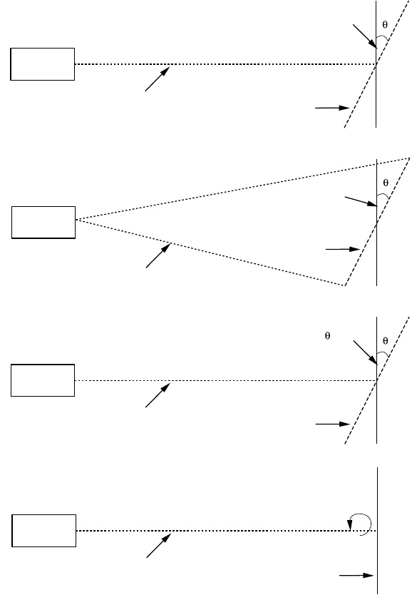
Psion Teklogix 7535 Hand-Held Computer User Manual 283
Chapter 8: Specifications
SE1200 Advanced Long Range & SE2223 PDF Specs
Figure 8.1 Pitch, Skew And Specular Dead Zone
Pitch Pitch Angle
Scan Beam
Scan Beam
Scan Pattern
Skew Angle
Barcode Surface
Barcode Surface
Barcode Surface
Scanner
Side View
Top View
Side View
Scanner
Scanner
Skew
Specular Dead Zone < 2º
Scan Beam Barcode Surface
Side View
Scanner
Roll

Chapter 8: Specifications
Decode Zones
284 Psion Teklogix 7535 Hand-Held Computer User Manual
8.4.3 Decode Zones
Table 8.3 Decode Zones – HP, LR And ALR
Table 8.4 Decode Zones – PDF Scanner
8.5 External Scanner Specifications
8.5.1 PowerScan™ LR and XLR Industrial Scanner Specs
Communication
Undecoded Standard and Intermec-compatible.
Mechanical
Dimensions 6.9 x 11.2 x 18.3 cm (2.7 x 4.4 x 7.2 in)
Weight Scanner - 280 g (9.9 ozs)
Cable (82.3 cm 32 in) - 176 g (6.2 ozs)
Cable lengths Collapsed: 81 cm (32 in)
Max working: 183 cm (72 in)
Bar Code Read Distance
High
Performance Long Range Advanced
Long Range
Min Max Min Max Min Max
5 mil 3.0"4.5"
7.5 mil 3.0"8.5"
10 mil 2.5"12.5"13.0"17.5"
15 mil 2.5"18.5"8.5"33.5"20.0"50.0"
20 mil 2.5"20.5"9.5"38.5"30.0"60.0"
40 mil 3.0"29.5"9.5"79.5"30.0"98.0"
55 mil 3.5"35.5"9.5"89.5"27.0"115.0"
Bar Code Raster Laser Scanner
Read Distance
PDF Bar Codes S2223
Min Max
6.5 mil 2.5"6.5"
10 mil 2.5"9.5"
15 mil 2.5"15.5"
Psion Teklogix 7535 Hand-Held Computer User Manual 285
Chapter 8: Specifications
PowerScan™ LR and XLR Industrial Scanner Specs
Electrical
Operating voltage 4 VDC to 14 VDC
Operating current - nominal Undecoded: 75 mA @ 5 VDC
Decoded: 100 mA @ 5 VDC
Idling current - low power mode < 50 µA @ 5 VDC
Optical
Light source Extra bright 650 nm Visible Laser Diode
(VLD)
Scan System Frictionless lifetime flexure mechanism
Rate 35 scans/sec nominal
Depth of field - Long Range Paper Labels (decoded)
7.5 mil 6 to 10 in (15 to 25 cm)
10 mil 5 to 20 in (13 to 51 cm)
15 mil 5 to 32 in (13 to 81 cm)
20 mil 5 to 48 in (15 to 122 cm)
40 mil 8 to 85 in (20 to 216 cm)
55 mil 15 to 108 in (38 to 274 cm)
Reflective Labels (decoded)
40 mil 22 to 100 in (56 to 254 cm)
55 mil 30 to 104 in (76 to 366 cm)
70 mil 40 to 180 in (102 to 457 cm)
100 mil 45 to 264 in (114 to 671 cm)
Depth of Field-Extra Long Paper Labels (decoded)
Range 15 mil 28 to 60 in (71 to 152 cm)
20 mil 28 to 72 in (71 to 182 cm)
40 mil 28 to 144 in (71 to 144 cm)
55 mil 40 to 180 in (102 to 457)
Reflective Labels (decoded)
40 mil 40 to 180 in (102 to 457 cm)
70 mil 80 to 300 in (2032 to 762 cm)
100 mil 80 to 432 in (203 to 1097 cm)
Chapter 8: Specifications
PowerScan™ LR and XLR Industrial Scanner Specs
286 Psion Teklogix 7535 Hand-Held Computer User Manual
Print Contrast Ratio 25% minimum
Pitch ± 65˚
Skew ± 55˚
Ambient Light Immunity Artificial light: 1200 ft. candles.
Sunlight: 8000 ft. candles.
Environmental
Temperature Rating Operating: -22˚ to 122˚ F (-30˚ to 50˚ C)
Storage: -40˚ to 158˚ F (-40˚ to 70˚ C)
Humidity 5 to 95% NC
Shock (at 23˚ C) Withstands multiple 6 foot drops to concrete.
Vibration Meets MIL-STD-810E
Water and Dust IEC529 rating IP54DW
Decoding Capabilities
Auto-discriminates between: UPC A, E/EAN8, 13/JAN8, 13
(P2/P5, Code 128 EAN add-ons)
Code 128, MSI/Plessey, Code 39, Interleaved
2 of 5, Code 39 Full Ascii,
Standard 2 of 5, Code 93, Codabar,
Safety/Regulatory
Electrical Complies to: Gost R; TUV; UL; cUL
Emissions Complies to: FCC-A;EN55022-B
BCIQCNS13438; AS/NZS3548;
VCCI-B
Laser Classification CDRH Class 2;IEC60825 Class 2
Psion Teklogix 7535 Hand-Held Computer User Manual 287
Chapter 8: Specifications
PowerScan™ Standard Range Scanner Specs
8.5.2 PowerScan™ Standard Range Scanner Specs
Communication
Undecoded Standard and Intermec-compatible.
Mechanical
Dimensions 6.9 x 11.2 x 18.3 cm (2.7 x 4.4 x 7.2 in)
Weight Scanner - 280 g (9.9 ozs)
Cable (82.3 cm 32 in) - 176 g (6.2 ozs)
Cable lengths Collapsed: 81 cm (32 in)
Max working: 183 cm (72 in)
Optical
Light source Extra bright 650 nm Visible Laser Diode
(VLD)
Scan System Frictionless lifetime flexure mechanism
Rate 35 scans/sec nominal
Depth of field - Standard Paper Labels (decoded)
7.5 mil 3.0 to 6 in (9 to 15 cm)
10 mil 1.5 to 15 in (4 to 38 cm)
15 mil 1.0 to 25 in (2.5 to 64 cm)
20 mil 1.0 to 35 in (2.5 to 89 cm)
(paper) 55 mil 6.0 to 60 in (15 to 152 cm)
High Density (decoded)
3 mil 1.0 to 2 in (2.5 to 5.1 cm)
4 mil 1.0 to 3 in (2.5 to 8 cm)
5 mil 0.8 to 3.8 in (2 to 10 cm)
7.5 mil 0.6 to 4.5 in (1.5 to 11 cm)
10 mil 0.2 to 5.5 in (0.5 to 14 cm)
Print Contrast Ratio 25% minimum
Pitch ± 65˚
Skew ± 55˚
Ambient Light Immunity Artificial light: 1200 ft. candles.
Sunlight: 8000 ft. candles.
Chapter 8: Specifications
Lithium-Ion Battery Pack
288 Psion Teklogix 7535 Hand-Held Computer User Manual
Electrical
Operating voltage 4 VDC to 14 VDC
Operating current - nominal Undecoded: 75 mA @ 5 VDC
Decoded: 100 mA @ 5 VDC
Idling current - low power mode < 50 µA @ 5 VDC
Environmental
Temperature Rating Operating: -22˚ to 122˚ F (-30˚ to 50˚ C)
Storage: -40˚ to 158˚ F (-40˚ to 70˚ C)
Humidity 5 to 95% NC
Shock (at 23˚ C) Withstands multiple 6 foot drops to concrete.
Vibration Meets MIL-STD-810E
Water and Dust IEC529 rating IP54DW
Decoding Capabilities
Auto-discriminates between: UPC A, E/EAN8, 13/JAN8, 13
(P2/P5, Code 128 EAN add-ons)
Code 128, MSI/Plessey, Code 39,
Interleaved 2 of 5, Code 39 Full Ascii,
Standard 2 of 5, Code 93, Codabar,
Safety/Regulatory
Electrical Complies to: Gost R; TUV; UL; cUL
Emissions Complies to: FCC-A;EN55022-B
BCIQCNS13438; AS/NZS3548;
VCCI-B
Laser Classification CDRH Class 2;IEC60825 Class 2
8.6 Lithium-Ion Battery Pack
Technology Lithium-Ion (Li-Ion)
Operating Temperature -20˚C to 60˚C (-4˚F to 140˚F)
Charge Temperature 0˚C to 39˚C (32˚F to 102˚F)
Storage Temperature -30˚C to 60˚C (-22˚F to 140˚C)
(Storage at elevated temperatures is not
recommended.)
Charge Cycles Minimum of 300 charge cycles with no deg-
Psion Teklogix 7535 Hand-Held Computer User Manual 289
Chapter 8: Specifications
Lithium-Ion Battery Pack
radation below 70% of nominal capacity
Charge Time Charge time is typically 1.5 hours.
Voltage 7.4 V nominal (6V min. to 8.4V max.)
Cell Configuration 2 series connected cells
Capacity 1800 mAh nominal at 300mA discharge
20˚C to 6.0V (minimum)
Supported Chargers 6-Gang Charger
Combo Charger
Combo Docking Station
Quad Docking Station

Psion Teklogix 7535 Hand-Held Computer User Manual A-1
APPENDIX A
A
SUPPORT SERVICES AND WORLDWIDE OFFICES
A.1 Support Services
Psion Teklogix provides a complete range of product support services to its
customers worldwide. These services include post-installation technical support and
product repairs.
A.1.1 Canada and USA: Technical Support and Repair Services
In Canada and the U.S.A. these services can be accessed through the Psion Teklogix
Helpdesk. The Helpdesk coordinates repairs, helps you troubleshoot problems over
the phone, and arranges for technicians or engineers to come to your site.
Canadian and U.S. customers may receive access to technical support services,
ranging from phone support to emergency on-site system support, by calling the
toll-free number below, or via our secure web site.
Note: Customers calling the toll-free number should have their Psion Teklogix
customer number or trouble ticket number available.
Voice: 1 800 387-8898
Fax: 1 905 812-6304
Web Site: http://service.psionteklogix.com
A.1.2 International Support
For technical support outside of Canada or the U.S.A., please contact your local
Psion Teklogix office. See page A-3 for a listing of worldwide offices.
Psion Teklogix 7535 Hand-Held Computer User Manual A-3
A.2 WORLDWIDE OFFICES
COMPANY HEADQUARTERS
AND CANADIAN SERVICE CENTRE
Psion Teklogix Inc.
2100 Meadowvale Boulevard
Mississauga
Ontario
Canada L5N 7J9
Tel: +1 905 813 9900
Fax: +1 905 812 6300
Email: salescdn@psion.com
INTERNATIONAL SUBSIDIARIES
Psion Teklogix GmbH
Jakob Kaiser Straße 3
D-47877 Willich Münchheide
Deutschland
Tel: +49 2154 9282 0
Fax: +49 2154 9282 59
Email: info@teklogix.de
Psion Teklogix S.A.
La Duranne
135 Rue Rene Descartes
BP 421000
13591 Aix-En-Provence
Cedex 3; France
Tel: +33 (0) 4.42.908.809
Fax: +33 (0) 4.42.908.888
Email: tekeuro@psion.com
Psion Teklogix LTD.
3, Lancaster Court
Coronation Road High Wycombe
Bucks HP123TD, England
Tel: +44 1494 450666
Fax: +44 1494 450155
WWW: www.teklogix.co.uk
Email: tekuk@psion.com
Psion Teklogix AB
Stora Badhusgatan 18-20
411 21 Göthenburg, Sweden
Tel: +46 31 13 15 50
Fax: +46 31 13 57 80
Email: info@teklogix.se
NORTH AMERICAN HEADQUARTERS
AND U.S. SERVICE CENTRE
Psion Teklogix Corp.
1810 Airport Exchange Boulevard
Suite 500
Erlanger, Kentucky
USA 41018
Tel: +1 859 371 6006
Fax: +1 859 371 6422
Email: salesusa@psion.com
Psion Teklogix Finland
Metsänneidonkuja 8
02130 Espoo
Finland
Tel: +358 9 4307 8390
Fax: +358 9 4307 8395
Email: tekeuro@psion.com
Psion Teklogix Danmark
Vesterballevej 4-6
7000 Fredericia
Danmark
Tel: +45 76 24 0133
Fax: +45 75 94 4679
Email: tedk@psion.com
Psion Teklogix Italia S.r.I
Via Galilei, 47
20092 Cinisello Balsamo
Milan, Italy
Tel: +39 2 6604 5410
Fax: +39 2 6604 5412
Email: tkxitalia@psion.com
Psion Teklogix Benelux
Nieuwe weg 1
2070 Zwijndrecht
Belgium
Tel: +32 (0)3 250 22 00
Fax: +32 (0)3 250 22 20
Email: info@psionteklogix.be
Psion Asia Pacific Pte. Ltd.
210 South Bridge Road
#03-01 Singapore 058759
Tel: +65 67358108
Fax: +65 67335990
E-mail: teksing@teklogix.com
Psion Teklogix de Mexico, S.A. de C.V.
Sierra Mojada 626, 2º Piso
Col. Lomas Barrilaco, C.P. 11010
Mexico, D.F., Mexico
Tel: ++52 55 5 327 1124
Fax: +52 5 327 1123
Email: salesusa@psion.com
Psion Teklogix do Brasil, Ltda.
Al. Casa Branca, 851 - conj. 101 e 102
São Paulo - SP - 01408-001
Brasil
Tel: +55 11 3064 0868
Fax: +55 11 3068 8198
WWW: www.teklogixbrasil.com.br
Email: tekbr@psion.com
Chile Psion Teklogix International Inc.
Avenida Vitacura 2909, Oficina 703
Las Condes
Santiago, Chile
Tel: +56 2 334 9344
Fax: +56 2 233 3868
Email: ventas@psion.com
A-4Psion Teklogix 7535 Hand-Held Computer User Manual
Psion Teklogix de Argentina, S.A.
Avenida Moreau de Justo 1180
Piso 1, Oficina C-105
Buenos Aires 1107
Argentina
Tel: +54 11 4343 0193
Fax: +54 11 4343 6310
Email: tekar@psion.com
Psion Teklogix España, S.L.
Cityparc Ronda de Dalt
Ctra. Hospitalet 147-149
Edificio Atenas 2˚ 3ª
08940 Cornellà de Llobregat (Barcelona)
España
Tel: +34 9 3475 0220
Fax: +34 9 3475 0230
Email: teklogix@apdo.com
Psion Teklogix Africa
Postnet Suite 39, Private Bag x11
Halfwayhouse, 1685 Ground Floor East
Waterfall Edge Phase 2, Waterfall Park
Bekker Road MIDRAND 1685
South Africa
Tel: 27-11-805-7440/1/2
Fax: 27-11-805-7444
Psion Teklogix Systems India Pvt. Ltd.
M-74, 1st Floor, “M” Block Market
Greater Kailash-Il
New Delhi - 110048
India
Tel: +91 11 621 9257
Fax: +91 11 621 9076
Email: tekind@psion.com
Psion Teklogix B.V.
Venrayseweg 57,
5928 NZ Venlo
Nederlands
Tel: 0031-77-32400.44
Fax: 0031-77-32400.53
A.3 WORLD WIDE WEB
www.psionteklogix.com
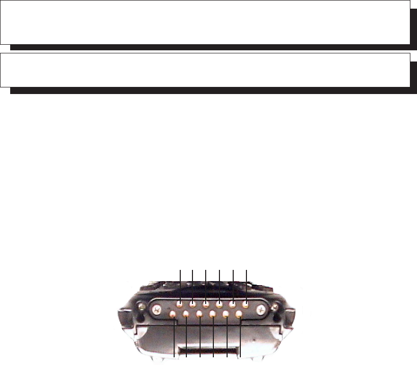
Psion Teklogix 7535 Hand-Held Computer User Manual B-1
APPENDIX B
B
PORT PINOUTS
B.1 7535 Tether Port Pinout
The tether port connector incorporates multiplexed undecoded scanner, decoded
scanner, RS232 serial, and USB interfaces. In order for it to operate, a special wiring
scheme is needed. If you have a need to create cables for the tether port, contact
Psion Teklogix and request document # 1010008 “Instruction Tether Port Termina-
tion”. Attempting to interface to the tether connector without following this docu-
ment may cause damage to the 7535 or the tethered device.
B.2 Docking Station Connector
1. Ext 5V Switched. Used by external peripherals. 5V, 1A max.
2. RX Data. Console receive pin.
3. TX Data. Console transmit pin
4. DC Power In. External power adapter plus input (13-15V).
5. USB Host Minus. For connecting USB devices.
6. USB Host Plus. For connecting USB devices.
7. DC Power In. Same as pin 4.
8. Docking Station Id. Identifies device attached to the docking station.
Resistor between this pin and ground.
2 4 6 8 10 12
1 3 5 7 9 11
Appendix B: Port Pinouts
Battery Contacts
B-2 Psion Teklogix 7535 Hand-Held Computer User Manual
9. Ground.
10. USB Device Minus. When terminal operated as a USB device.
11. USB Device Plus. When terminal operated as a USB device.
12. Ground
B.3 Battery Contacts
These contacts represent right to left numbering with the 7535 docking port pointing
toward you.
1. Battery Plus
2. SMBUS CLK
3. Battery ID. Identifies battery type (2 cell-100K resistor to Battery
Negative, 3-cell 100K resistor to battery Negative).
4. SMBUS Data.
5. Battery Negative.

Psion Teklogix 7535 Hand-Held Computer User Manual C-1
APPENDIX C
C
USB SETUP APPLICATION
C.1 USB Setup
The USB Setup application (PN 1000997) is used to update a Windows PC so that it
can connect to a Psion Teklogix 7535.
System Requirements
•Windows® 2000 or XP
•ActiveSync 3.1 or later
The two driver classes that control USB communication are usbstor (for commu-
nication with a device running BooSt) and wceusbsh (for communication
through ActiveSync with a device running Windows CE). These drivers must be
updated with 7535-specific information so that the 7535 can be recognized by
your PC.
The install program:
•updates copies of the device installation scripts usbstor.inf and
wceusbsh.inf with Psion Teklogix-specific information,
•sets up a USB connection between the PC and the 7535, and
•installs the 7535 as a device on your PC. This may require notifying the
PC OS that the device should be reinstalled and then reconnecting the
USB device.
C.1.1 Launching The Application
The log file is initialized and the program introduction is written to it.
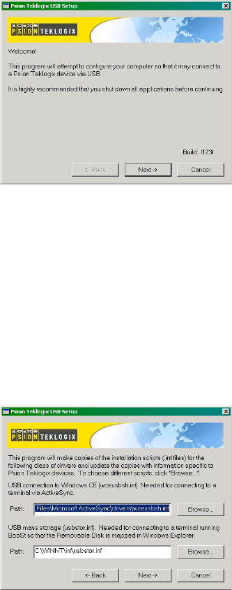
Appendix C: USB Setup Application
Pre-Installation: Updating usbstor.inf And wceusbsh.inf
C-2 Psion Teklogix 7535 Hand-Held Computer User Manual
C.1.2 Pre-Installation: Updating usbstor.inf And wceusbsh.inf
1. Welcome Dialogue Box:
You can click on the <Back> and <Next> buttons to navigate between
the pre-install windows. At any time during the pre-installation process,
you can tap on <Cancel> to exit the program.
•Shut down all other software programs – especially ActiveSync – to avoid a
restart request during installation.
•Tap on the <Next> button.
The program checks that ActiveSync is installed and that it is a supported
version – 3.1 or later. If the version installed on your PC is not supported,
you’ll need to exit the USB Setup application, and install a later version of
ActiveSync.
2. Device Driver INF File Selection Dialogue Box:
This dialogue box allows you to choose the paths of the appropriate
inf files. Default file paths are provided in this dialogue box.
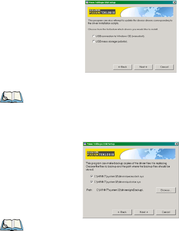
Psion Teklogix 7535 Hand-Held Computer User Manual C-3
Appendix C: USB Setup Application
Pre-Installation: Updating usbstor.inf And wceusbsh.inf
•If necessary, tap on the <Browse> buttons to select different paths for the
inf files.
3. Device Driver Install Selection Dialogue Box:
You can choose to have the device drivers installed immediately by
selecting the check box (√), or you can leave the check box blank and
Windows will install the 7535 the next time it is connected. It is recom-
mended that the device be installed immediately.
•Select the drivers you want to update – wceusbsh and usbstor.
•Tap on the <Next> button.
Note: None of the drivers are updated by default. To complete the process, you
must establish USB connections.
4. Device Driver Backup Selection Dialogue Box:
The USB Setup application will attempt to back up the driver .sys
files before attempting the installation. It specifies which files it will try
to back up and the location to which it will back them up.
Note: Both drivers are selected for backup by default. The backup directory is
<system directory>\drivers\ptxBackup.
Appendix C: USB Setup Application
Installation: Installing The 7535 As a Device On Your PC
C-4 Psion Teklogix 7535 Hand-Held Computer User Manual
C.1.3 Installation: Installing The 7535 As a Device On Your PC
1. Install Dialogue Box:
The .sys files you selected are copied to the backup directory. If an
unknown error occurs during the backup, you are asked whether you’d
prefer to cancel the install or continue with the process. The
wceusbsh.inf and usbstor.inf files are updated.
2. If you indicated that the wceusbsh driver should be installed, the
Install dialogue box appears again. The USB Setup application will
attempt to install the drivers immediately. This will succeed only if a
valid USB connection to the device that is running Windows CE exists.
•If the install fails due to an unknown error, the install for this particular
driver is aborted.
•If the install fails because there was an inappropriate USB connection, there
are two possibilities:
•An appropriate USB connection was never established between the PC
and the 7535 running Windows CE. In this case, when an appropriate
USB connection with this device exists, Windows will automatically
attempt to install the device driver.
•An appropriate USB connection exists between the PC and the 7535
running Windows CE, but it has since been severed. Windows may or
may not attempt to automatically install the device drivers on the next
appropriate USB connection.
•A window is displayed where you can tap on <Cancel> to abort the
wceusbsh driver installation and continue. It also contains instructions to
boot your device into Windows CE and establish a USB connection
between the device and the PC. When you create the appropriate connec-
tion, Windows automatically installs the device drivers. The ‘Found New
Hardware’ wizard may appear. Your only interaction with this window is to
click on the <Finish> button.
•If this is the first appropriate connect between the device and the PC –
i.e., there was no previous devnode for the device in the system – the
<Continue> button is activated as soon as the connection is made. Where
there was a devnode present in the system and it has been marked for rein-
stall, the <Continue> button will not become active until Windows has
Psion Teklogix 7535 Hand-Held Computer User Manual C-5
Appendix C: USB Setup Application
Post Installation
completed the driver installation and the device is no longer marked for
reinstall. Only one devnode per device can be ‘unset’ when the device
drivers are finally installed.
3. If you indicated that the usbstor driver should be installed, the same
steps as described above are carried out for usbstor except that the
7535 must be running BooSt. (Press and hold down the <SCAN>
<BLUE> <ENTER> keys for a minimum of 6 seconds to launch the
BooSt program.) Keep in mind that a device running BooSt has a dif-
ferent hardware ID than when it is running Windows CE.
C.1.4 Post Installation
1. Done Dialogue Box:
This dialogue box indicates the success or failure of the installation.
•To view the log file, tap on the <Log File> button
•To exit the program, tap on the <Exit> button.

Psion Teklogix 7535 Hand-Held Computer User Manual I
Boldface indicates a parameter name.
INDEX
# of Cols (ANSI) 200
# of Cols (TESS) 214
# of Pages (ANSI) 199
# of Rows (ANSI) 199
# of Rows (TESS) 214
A
accents, adding (Custom Characters) 191
accessories
bar code readers, connecting 251
hand strap 14
picker cradle (7535) 268
pistol grip 15
acknowledged host number (ah) 168
acknowledged remote number (ar) 168
acknowledgements, transmitted (xa) 167
acknowledgements received 167
AcQ (# of messages sent but not acknowl-
edged by cellular master) 168
Addendum 125, 127, 128
addresses, network See also Network
addresses 244
Ad Hoc network 21
Advanced (wireless connection) 26
advanced long range (SE1223ALR)
scanner 282
ah (acknowledged host number) 168
AIAG
AIAG Character 228
AIAG Strip 123
Mixed AIAG 224
AIAG Character 228
AIAG Strip 123
aiming dot, duration of 120
All Fld Video 225
Alpha parameters 171, 174
ALR (advanced long range) scanner 282
ALT Key 37
anchor (viewport) 239
Anchor Column 240
Anchor Line 240
Anchor View
x origin 211, 227
y origin 211, 227
ANSI
# of Cols 200
# of Pages 199
# of Rows 199
Applications menu 194
arrow keys 163
auto-answerback string 203
Auto Login (Telnet Settings) 197
Auto Term# 195, 212
Group 195, 212
block mode 164, 204–205
Colour Override 202
configuration 162
Conn Type (connection type) 196
CR character 208
device attribute requests 163
device attribute string 203
disabling the keyboard/scanner 208
Edit Modes 209
ENTER key 163, 207
ENTER Pmpt (Telnet Settings) 197
ESC Prompt (Telnet Settings) 197
Func Key Remap (Telnet Settings)
198
Function key equivalents 163
Group Auto Term# 195, 212
Host (Telnet Settings) 197
Kbd Modes 206–208
keyboard lock 204
LF character 208
local editing mode 164, 202
Login (Telnet Settings) 198
Login Failed (Telnet Settings) 198
Login Prompt (Telnet Settings) 198
Media Copy 204
mnemonics 209
multiple sessions 194
Password (Telnet Settings) 198
Password Echo (Telnet Settings) 198

Index
II Psion Teklogix 7535 Hand-Held Computer User Manual
Boldface indicates a parameter name.
Password Prompt (Telnet Settings)
198
Port 197
sessions, closing 165
sessions, establishing new 165
sessions, listing 165
sessions, moving between 165
settings 195–211
Telnet connection 196
Terminal # 195
transmitting data 124, 126, 204
Xmit Modes 202–205
802.IQ connection 196
ANSI Settings
Connection Type - Telnet & TCP Direct
196
Screen settings 199
AP/Controller mac , displaying 167
App. parameter 215
appearance (display colour scheme) 91
Append Enter 223
Append F0 223
appending to bar codes
characters 120, 124, 126
Applications
ANSI Settings 195–211
character attributes (TESS) 216
Character Sets (TESS) 216
Fields parameters (TESS) 224
Host Conn (ANSI) 196
Host Conn (TESS) 213
menu (Applications) 194
Scanner parameters (TESS) 223
Screen parameters (ANSI) 199
Screen parameters (TESS) 214
TESS Settings 212–227
Type and Title 194
approvals
7535 (including scanner) 278
ar (acknowledged remote number) 168
arrow keys 163
completing a data field 156, 225
cycling through special
characters 172
Enh Mode, using 226
moving the cursor 36
Arrow mode 206
Arrows 243
ASCII
decimal equivalents of characters 218
Full Ascii 122
matching fields 217
Async In 210
attributes, video 200–201, 225
Audio 183
audio indicators
adjusting volume 48
description of beep conditions 47
volume adjustment using the BLUE
key 48
authentication, network (Shared Mode) 22
Auto-Answer 203
Auto Login (ANSI Telnet Settings) 197
Auto Radio Addr 179, 246
AutoRep Fn (function key sent
to host) 218
AutoRep T/O 218
auto tab fields 155
Auto Term# (ANSI) 195, 212
Auto wrap 209
B
backlight
display 89
intensity 40
keyboard 40
backspace (CTRL H) 207
bar code
AIAG 224
appending to 120, 124, 126
connecting bar code reader 251
decodes required 120
decoding edge-to-edge 120
displaying type of bar code 118
external bar code reader 251
parameters 121–132
prefix character 124, 126
Security 120
stripping characters 124, 126
suffix character 124, 126
symbologies
Codabar 128
Code 11 128
Code 128 124
Code 39 122–123
Code 93 128
Discrete 2 of 5 129
EAN 13 125

Psion Teklogix 7535 Hand-Held Computer User Manual III
Index
Boldface indicates a parameter name.
EAN 8 126
IATA 2 of 5 130
Interleaved 2 of 5 129
MSI Plessey 129
UPC A 127
UPC E 127
Barcode Character 228
bar-code-only fields 155
bar code reader
external (specs) 280
external scanner, operation of 251
integrated scanner, operation of 48
internal or integrated (specs) 279
batteries
a description of 251
capacity dialogue box 100
charger dialogue box 103
charging 13, 33
gauge 46
installing 32, 33
installing in 7535 17
power info 71
power saving scheme dialogue box 101
removing 32
run time, maximizing 53
safety precautions 252
specifications 288
suspend threshold dialogue box 102
battery charger
safety instructions 253–254
battery pack 251–253
battery safety 252–254
battery See also batteries 251
Baud 237
beacons received (rb) 167
beacon timeouts (bt) 167
Beam Lockout 224
beep conditions 183
beeper
adjusting volume 48
description of beep conditions 47
volume adjustment using the BLUE
key 48
beeper sounds 183
Beep Tone and Beep Time 183
bell (CTRL G) 207
Binary print 219
BKSP (DEL Key) 37
BKSP/DEL Key
TESS sessions, BKSP key behaviour in
157
TESS sessions, DEL key behaviour in
158
blinking video attribute 201, 225
Block Cursor 188
block mode, ANSI 164, 204–205
Bluetooth radio
ISM band 106
Bluetooth setup 106
GPRS setup 111
peripherals 268
bold video attribute 200, 225
Bootloader (Shutdown menu) 75
bootnum
802.IQ 167
802.IQ, displaying 167
Bright For (backlight) 90
Brightness 242
Brk for Attn 231
bt (beacon timeouts) 167
Buffer 238
C
ca (cellular address) 168
cable diagrams B-1
calibrating (touchscreen) 41, 104
cellular address (ca) 168
changing password (Start Menu security)
69
changing softkey labels (Label F1-F5)
201
changing softkey labels (Label F1-F6)
215
Character parameters (TESS) 216
characters
appending to bar codes 124, 126
Char Set, choosing (TESS) 216
cycling through 172
decimal values of 218
EOB chars 205
EOL chars 205
Lower (ANSI) 210
prefix 124, 126
stripping 124, 126
suffix 124, 126
Upper (ANSI) 210
character set (Tether & Console Port) 236
Character Sets

Index
IV Psion Teklogix 7535 Hand-Held Computer User Manual
Boldface indicates a parameter name.
Host Char Set 210
character sets
choosing in TESS 216
Lower (ANSI) 210
Upper (ANSI) 210
charger
descriptions of 33
safety instructions 253–254
charging (battery) 13
Char Set (TESS) 216
Check Digit 128
check digit 125, 128, 129, 130
Check Digit, One 129
Clear Entry Fields 228
Click Data (scanner double-click) 120
Click Time (scanner double-click)
119
CLR/DEL key
Local Echo mode (ANSI) 207
CLR Key 244
Codabar 128
Code 11 128
Code 128 124
Code 39 122–123
Code 93 128
Cold Reset (Shutdown menu) 75
Colour Override 202, 216
Column Offset 240
columns
number of in ANSI screen 200
number of in TESS screen 214
Command Prompt 72
Command Region Up, Down, Left &
Right 229
Communities 136
configuring IEEE 802.11 radio 18
configuring softkey labels (Label F1-F5)
201
configuring softkey labels (Label F1-F6)
215
connecting
Auto Login (ANSI Telnet Settings)
197
ENTER Pmpt (ANSI Telnet
Settings) 197
Login (ANSI Telnet Settings) 198
Login Failed (ANSI Telnet Settings)
198
Login Prompt (ANSI Telnet
Settings) 198
Password (ANSI Telnet Settings) 198
Password Echo (ANSI Telnet
Settings) 198
Password Prompt (ANSI Telnet
Settings) 198
connection, host 196, 213
Conn Type (connection type) 196, 213
Contact 135
Cont Nxt Fld 223
contrast, adjusting 41
contrast, adjusting display 41
control codes 209
control panel
accessing 83
basic setup 88
Display Properties 88
icons 84
keyboard properties 92
power management properties 100
stylus properties 103
Convert to UPC-A 127
country code 125
CR/LF
CTRL J 207
LF character 208
Newline 208
cradle See also Picker cradle 268
CRC (serial I/O) 222, 223
CTRL commands
CTRL a 165
CTRL c 160
CTRL f 156
CTRL G (Bell) 207
CTRL h 161
CTRL H (Backspace) 207
CTRL h (host select) 160
CTRL i 156
CTRL I (Tab) 207
CTRL J (Line Feed) 207
CTRL K (Vertical Tab) 207
CTRL L 161
CTRL L (Form Feed) 207
CTRL p (reprint) 160
CTRL r 156
CTRL s 159
CTRL s (status, displaying
continuously) 160

Psion Teklogix 7535 Hand-Held Computer User Manual V
Index
Boldface indicates a parameter name.
CTRL t 159
CTRL t (status, display with unit #) 160
CTRL u 156
CTRL w 159
CTRL w (status, display in Lock B & H
mode) 160
CTRL Key 37
cursor
changing shape of 188
Enh Edit mode 226
field advance (tab) 155
field backspace 155
field exit 155
Field Order 224
home 155
linefeed mode (ANSI) 207
moving between fields 206, 224
newline mode (ANSI) 207
Custom Characters 191
cycle tasks 71
D
data
entering 155, 226
Ign Bcode_fld 226
with a bar code reader 251
serial I/O 222
Serial In/Out 221
transmitting from the terminal 208, 225
transmitting from the 7535 155, 202
Data Bits 237
data stream type (typ) 168
dead zone 283
decimal values of keys 218
decode zones (internal scanners) 284
decoding bar codes
decodes required 120
Security 120
2-D scanner 284
decrementing parameters 170, 174
Default Colour 193
Default font 200, 226
DEFAULT key (F3) 148
DEFLT key (F3) 175
DEL (BKSP) Key 37
DEL/CLR key
BKSP key (ANSI) 207
Local Echo mode (ANSI) 207
desktop connection, remote 83
Dev Attr 203
device attribute requests 163
device attribute string 203
dialogue box, using 76
digit
check digit 125, 128, 129, 130
number system 127, 128
Dim For (backlight) 90
Disable kbd 208
disabling/enabling Y/N parameters 171,
174
disconnecting
ESC Prompt (ANSI Telnet Settings)
197
Discrete 2 of 5 129
Disp controls 209
display
Anchor Column 240
Anchor Line 240
Anchor View 211, 227
appearance (colour scheme) 91
backlight 89
backlight, adjusting 40
Brightness 242
contrast (control panel) 88
contrast, adjusting 41
Display Properties 88
Display Shift 187
Field Scroll 214
ICH/DCH controls 209
Line Scrolling 242
moving 188
Origin Scroll 214
Panning 242
positioning 214
split screens 188
Use Increment 188
video attributes 200–201, 225
viewport, mapping 239
Wraparound 242
X-Increment 188
Y-Increment 188
display contrast, adjusting 41
displaying TESS version number 159
Display Menu
selecting a TESS session 154
Display menu 168
Display Properties 88
Display Shift 187

Index
VI Psion Teklogix 7535 Hand-Held Computer User Manual
Boldface indicates a parameter name.
docking device icons 47
docking station
uploading data using 56
Dot Time 120
double-click
appending characters to a decoded
bar code 120
scanner trigger 119
Double-Tap (stylus settings) 104
E
EAN/UCC 128 125
EAN 13 125
EAN 8 126
EAP (Extensible Authentication Protocol)
23
Echo Mode 206
Edit extent 209
editing 202
Edit Modes 209
edit modes, TESS 156
empty entry fields 218
Emulation
2392 Telnet 227
AIAG Character 228
Barcode Character 228
Clear Entry Fields 228
Command Region Up, Down, Left
& Right 229
Enable Alarm 229
Features 228
Fixed Field Overhd 229
Passthru Printing 228
Send CR with FKEY 227
Serial IO Character 229
3274 Telnet 230
BRK for Attn 231
Features 231
FKEY0-39 232
Fujitsu Host 230
Intl EBCDIC 230
IP for SysReq 230
LU Name 231
LU Name Enabled 231
Null In Fields 230
5250 Telnet 232
Features 234
FKEY0-39 234
Intl EBCDIC 233
LU Name Enabled 233
LU Name Prefix 233
Nulls In Fields 233
Remap Underline To 233
Term Type 233
WEC (Write Error Code) 232
Emulation 227
emulation keys
field advance (tab) 155
field backspace 155
field exit 155
home 155
tab (field advance) 155
emulation keys, IBM 5250 155
Enable Alarm 229
enabling/disabling Y/N parameters 171,
174
End (ANSI) 210
Enh Edit Mode (TESS) 226
ENTER key 163
completing a data field 156
CR/LF character 208
Enter on Arrows 225
Local Echo mode (ANSI) 207
newline mode (ANSI) 207
Xmit Enter 208
Enter On Arr 225
ENTER Pmpt (ANSI Telnet Settings) 197
Enter To F0 225
ENT Key 244
entry fields 154
empty fields 218
Function keys 226
hidden match 217
Ign Bcode_fld 226
video attributes 200–201, 225
visible match 217
Entry Mode 226
entry mode 226
EOB chars 205
EOL chars 205
Erasure Mode 209
Error Accept 123
Error Tone and Error Time 183
ESC Key 37
ESC Prompt (ANSI Telnet Settings) 197
Estimated Battery Backup Time 102
Estimated Operating Time 102

Psion Teklogix 7535 Hand-Held Computer User Manual VII
Index
Boldface indicates a parameter name.
Extensible Authentication Protocol (EAP)
23
F
Fcursor mode 156
features (of 7535) 5
Features (2392 Telnet) 228
Features (3274 Telnet) 231
Features (5250 Telnet) 234
FETM 204
fh (forward host number) 168
field advance 155
field advance key function 155
field backspace 155
field backspace key function 155
field exit key function 155
Field mode 156
Field Order 224
fields
Arrow mode 206
auto-tab fields 155
bar-code-only fields 155
completing a data field 156, 225
Enh Edit mode 226
entry fields 154, 218
field advance (tab) 155
field backspace 155
field exit 155
Field Order 224
Field Scroll 214
Field Size 123
fixed fields 154
hidden match 217
home 155
Ign Bcode_fld 226
“insert” mode 208, 226
match fields 154
“replace” mode 208, 226
serial I/O fields 155
Serial In/Out 221
size 123
tab (field advance) 155
“transmit on” 155
video attributes 200–201, 225
visible match 217
Fields parameters (for TESS Settings) 224
Fill Chr 218
Fixed Field Overhd 229
fixed fields 154
F Keys (function keys) 244
FKEY0-39 232, 234
Flow Control 237
Follow Cursor 242
font
Default Font 200, 226
Font Chg 186
Font Override 193
fonts, changing 150
Foreground & Background (Colour
Override) 202, 216
Foreground & Background (Default
Colour) 193
Format Effector Transfer
Mode (FETM) 204
form feed (CTRL L) 207
forward host number (fh) 168
forward remote number (fr) 168
fr (forward remote number) 168
Fujitsu Host 230
Full Ascii 122
Func Key Remap (ANSI Telnet Settings)
198
Function Keys 147
softkeys 148
36-key keyboard 147
58-key keyboard 147
Function keys 163
ANSI equivalents 163
auto reply mode 218
completing a data field 156
entering data 226
executing procedures from the
local menu 161
FKEY0-39 (3274 Telnet) 232
FKEY0-39 (5250 Telnet) 234
Label F1-F5, changing 201
Label F1-F6, changing 215
Open Fky Only 226
serial I/O 222
G
GATM (Guarded Area Transfer
Mode) 205
GPRS (bluetooth) 111
Group (ANSI Auto Term#) 195, 212
H
hand strap, installing on 7535 14

Index
VIII Psion Teklogix 7535 Hand-Held Computer User Manual
Boldface indicates a parameter name.
helpdesk 4, A-1
hidden fields match 217
high performance (SE1200HP) scanner
281
H Match Chr 217
home key function 155
host
multiple hosts 161
selecting a host 161
switching between hosts 219
Host (ANSI Telnet Settings) 197
Host (TESS Connection Type) 213
Host Char Set 210
Host Connection
ANSI 196
TESS 213
Host echo mode 206
host select (CTRL h) 160
host terminal number of session (tn) 168
I
I/O fields 155
IATA 2 of 5 130
IBM 5250 Emulation Keys 155
ICD/DCH controls, displaying 209
IEEE radio, configuring 18
Ign Bcode_fld 226
imager (2D) scanner 51
Include Check 125, 126, 128, 129, 130
Include Check (Discrete 2 of 5
symbology) 130
Include Check (Interleaved 2 of 5
symbology) 129
Include Chk 122, 127, 128
Include Country 125
Include Number Sys 127, 128
Include Sym (Code 128) 124
incrementing parameters 170, 174
Indicators 182
indicators
battery gauge 46
docking devices 47
LED functions 42
modifier keys 46
onscreen 45
radio signal quality 46
scanner message 50, 51
security level 47
status area 153
task bar 66
tethered device 47
inf usbstor, installing C-4
usbstor, updating C-2
wceusbsh, installing C-4
wceusbsh, updating C-2
Infrastructure network 21
initialized messages, transmitted (802.IQv1
xi) See xi (transmitted initialize
messages) 167
Initial RTT 180, 247
Input 133
input
bar-code-only fields 155
bar code reader 251
I/O fields 221
Input tmo 238
“insert” mode 208, 226
Open Fky Only 226
Output tmo 238
“replace” mode 208, 226
serial I/O 222
serial I/O fields 155
Serial In/Out 221
Input Panel (control panel) 87
Input Tmo 238
Insert mode 156
“insert” mode 208, 226
installation
hand strap 14
pistol grip 15
integrated scanner option 48
Intensity (7035 backlighting) 90, 93
Interleaved 2 of 5 129
Internet Explorer 72
Intl EBCDIC 230, 233
IP address, assigning 24
IP for SysReq 230
ISM band, Bluetooth radio 106
ITF Check (Discrete 2 of 5 symbology)
130
ITF Check (IATA 2 of 5 symbology) 130
ITF Chk (I 2 of 5 symbology) 129
I 2 of 5
Short Code 120
K
Kbd lock 204

Psion Teklogix 7535 Hand-Held Computer User Manual IX
Index
Boldface indicates a parameter name.
Kbd Locked 220
Kbd Modes 206–208
keyboard
compatibility with VT220 ANSI
keyboard 163
disabling the keyboard 208
function keys 163
Kbd modes 206–208
key repeat 92, 93
lock 204, 220
lock messages 160
one shot mode 94
36-key keyboard 38
58-key 37
Keyboard (Tekterm) 181
keyboard backlight 40
keyboard keys 35
ALT 37
arrow keys 36
BKSP 37
CTRL 37
DEFAULT key (F3) 148
DEL 37
ESC 37
function keys, accessing 147
LITERAL key (F5) 149
macro keys 95, 149, 181
modifiers 35
navigating using the keyboard 62
NEXT key (F1) 148
one shot mode 94
PREVIOUS key (F2) 148
SAVE key (F4) 149
SCAN 37
SHIFT 36
softkeys 148
SPACE 37
TAB 37
keyboard mapping (Scan-See) 244
keyboard modes 150
Keyboard Properties 92, 93
backlight 93
one shot mode 94
key function
field advance (tab) 155
field backspace 155
field exit 155
home 155
tab (field advance) 155
Key Index, assigning 22
Key Repeat tab 92
keys
alpha keys, 36-key keyboard 38
emulation keys, IBM 5250 155
transmit key 204
L
Label F1-F5 201
Label F1-F6 215
labels, changing softkey (Label F1-F5)
201
labels, changing softkey (Label F1-F6)
215
launching
DOS 168
Parameters menu 168
Tekterm 168
Lcl Process 161, 219
LED
charge 43
functions (7535) 42
receive 44
scan 44
transmit 44
LED Scan-See
Brightness 242
LF/CR
CTRL J 207
LF character 208
Newline 208
Line Offset 240
Line Scrolling 242
LITERAL key (F5) 149
Lithium-Ion batteries
installing 33
removing 32
local
editing mode, ANSI 164, 202
Local echo mode 206
menu 161
procedures 161
process 161, 219
Save on Reset 219
Location 135
“LOCK–B” message 160, 214
locked keyboard 204, 220
locked 7535 218
“LOCK–H” message 160, 214

Index
XPsion Teklogix 7535 Hand-Held Computer User Manual
Boldface indicates a parameter name.
lock time, decreasing with
queuing mode 162
Login (ANSI Telnet Settings) 198
Login Failed (ANSI Telnet Settings) 198
Login Prompt (ANSI Telnet Settings) 198
long range (SE1200LR) scanner 281
Lower (ANSI Host Char Set) 210
LU Name 231
LU Name Enabled 231, 233
LU Name Prefix 233
M
MAC address, access point/controller 167
MAC address, 7535 167
Macro keys
accessing 149
executing a macro 96, 97
Macros menu, accessing 95, 181
recording and saving 95
36-key keyboard 149
58-key keyboard 149
Main Battery Status 102
maintenance (7535) 56
mapping keyboard (Scan-See) 244
mapping viewport 239
match fields 154
MATM 205
Media Copy (ANSI) 204
memory, resetting 175
menu, local 161
Menu mode
taskbar (switching between apps) 152
menus, working with 169
message mask (msk) 168
messages
enabling/disabling next message 220
“LOCK–B” 160, 214
“LOCK–H” 160, 214
“NEXT–B” 161, 162
“NEXT–H” 161, 162
“RESET: Press Enter” 154
Scan Indicator 119
scanner warning message 119
Scan Result 118
TESS status message 159
messages, retransmitting (802.IQv1 xr) See
xr (retransmissions) 168
messages received (rm) 167
messages transmitted (xm) 167
milestone 220
Mixed AIAG 224
mnemonics (ANSI) 209
mode
serial I/O 221
Model 7000
Brightness 242
modes, keyboard 150
modifier keys 35
locking 36
One Shot Mode 94
unlocking 36
Mod 10 Check 123, 130
Mod 10 Check (Discrete 2 of 5
symbology) 129
Mod 10 Chk (I 2 of 5 symbology) 129
Mod 43 Check 123
moving the display 188, 214
MSI Plessey 129
msk (message mask) 168
multiple
ANSI sessions 194
applications 194
hosts 161
TESS sessions 194
Multiple Area Transfer
Mode (MATM) 205
N
Name 137
name servers, assigning 25
network
Ad Hoc 21
connection, monitoring 55
control panel settings 244
infrastructure 21
Network addresses 244
network authentication (Shared Mode) 22
Network Key, assigning 22
Newline 208
“NEXT–B” message 161, 162
“NEXT–H” message 161, 162
NEXT key (F1) 148
Next X 220
Null In Fields 230
Nulls In Fields 233
number
of columns (ANSI) 200
of columns (TESS) 214

Psion Teklogix 7535 Hand-Held Computer User Manual XI
Index
Boldface indicates a parameter name.
of pages (ANSI) 199
of rows (ANSI) 199
of rows (TESS) 214
Terminal # (ANSI) 162, 195
Terminal # (TESS) 154
number system digit 127, 128
numeric fields (Rjct if Alpha) 224
numeric parameters 170, 174
numeric parameters, minimum/maximum
limits to 170, 174
O
Off & On buttons 16, 34
offices list 4, A-3
off-line 7535
using local procedures 161
offset (viewport) 239
On & Off button 16, 34
One Check Digit 129
one dimensional internal scanner 50
One Shot Mode 94
ON Threshold 90, 93
Open Fky Only 226
order of fields in TESS screen 224
Origin Scroll 214
Output 133
output/input fields, serial port 221
Output Tmo 238
P
pages
# of Cols (TESS) 214
# of Columns (ANSI) 200
# of Pages (ANSI) 199
# of Rows (ANSI) 199
# of Rows (TESS) 214
positioning 214
queuing mode 162
reprinting 160
size/shape 200
Pages Saved (TESS) 215
Panning 242
parameters
Alpha parameters 171, 174
numeric 170, 174
saving changes to 175
string entry 171, 172, 174
Y/N (boolean) 171, 174
Parity 237
Passthru Printing 228
Password (ANSI Telnet Settings) 198
password, supervisor 186
Password Echo (ANSI Telnet Settings)
198
Password Prompt (ANSI Telnet Settings)
198
PDF internal scanner 51
period – ASCII decimal equivalent 218
peripherals, defining connections 235
picker cradle 268
installing cable 270
powered 10-55 VDC 268
powered 12 VDC 268
unpowered 268
pinouts B-1
pins – enabling for printing 219
pistol grip, installing on 7535 15
pitch, scanning 283
pivot (viewport) 239
pocket PC compatibility 83
Port (ANSI Telnet Settings) 197
Port (TESS Connection Type) 213
Port (802.IQ v2) 246
port pinouts B-1
ports
ANSI Connection Type 197
Baud 237
Buffer 238
Data Bits 237
Flow Control 237
Input tmo 238
Output tmo 238
parameters 236
Parity 237
Retries 238
serial 221
Serial In/Out 221
settings 235
settings (tether & console port) 235
settings for Tether and console 236
Stop Bits 237
TESS Connection Type 213
Test 238
Tether and Console Port settings 235
port settings (tether & console) 235–238
position
of screen 214
power information 71

Index
XII Psion Teklogix 7535 Hand-Held Computer User Manual
Boldface indicates a parameter name.
Power Management Properties 100
battery capacity 100
charger 103
scheme, power saving 101
suspend threshold 102
Power Mgmt 184
Power Scheme 101
power up 7535 16
preferred networks 26
prefix (serial I/O) 222
Prefix Char 124, 126
PREVIOUS key (F2) 148
PREV key (F2) 170, 173
printing
Binary print parameter 219
pages 160
Printer parameter 219
PrintScreen key 207
procedures, local 219
process, local 161, 219
Programs
Command Prompt 72
Internet Explorer 72
Remote Desktop Connection 72
Windows Explorer 72
protocol, 802.IQ v1 179
Protocol Type 180
punctuation marks, accessing (SHIFT
Key) 36
Q
Q (memory address of first message in
receive queue) 168
queue, memory address of first message in
receive queue (Q) 168
queue, transmissions waiting in (TxQ) 168
queuing
enabling/disabling next message 220
mode 162, 219
pages 162
Queuing parameter 161, 219
response time, improving 162
R
ra (received acknowledgements) 167
radio
adding new network connection 20
advanced settings of 26
Auto Radio Addr (narrow band radio)
246
Configure button 20
configuring 18
adding a new network connection
20
Ad Hoc 21
authentication, network 22
Configure button 20
Connect button 20
EAP (Extensible Authentication
Protocol) 23
Infrastructure 21
Key Index 22
Key Index, assigning 22
network authentication 22
Network Key 22
Network Key, assigning 22
wireless information 20
wireless properties 21
802.1X authentication 23
Connect button 20
Initial RTT (WaveLAN 802.11 DS
SS) 180, 247
IP address, assigning 24
name servers 25
preferred networks, arranging 26
Protocol Type 180
Radio Address (narrow band radio)
246
Radio Address (WaveLAN 802.11 DS
SS) 180
signal quality 46
statistics screen
802.IQ 166
wireless connection, setting up 18
802.IQ statistics screen 166
Radio Addr
Auto Radio Addr (narrow band radio)
246
Radio Address 180, 246
narrow band radio 246
WaveLAN 802.11 DS SS 180
802.IQ v1 180
radio address, automatic (802.IQ v1) 179
radio specifications 279
radio statistics screen
802.IQ 166
rb (received beacons) 167

Psion Teklogix 7535 Hand-Held Computer User Manual XIII
Index
Boldface indicates a parameter name.
recalibrating (touchscreen) 41, 104
received acknowledgements 167
received beacons (rb) 167
received messages (rm) 167
receive LED 44
Remap Underline To 233
Remote Desktop Connection 72
remote desktop connection 83
Repeat Delay (between key repeats) 93
Repeat Rate (of key repeats) 93
Repeat tab (key repeat settings) 92
Replace mode 156
“replace” mode 226
reprinting a page 160
“RESET: Press Enter” message 154
resetting
default parameter values 175
TESS session 160
7535 memory 175
resetting the 7535 28
response time, improving with
queuing mode 162
retransmissions (802.IQv1 xr) See xr
(retransmissions) 168
Retries 238
reverse video attribute 201, 225
Rights 137
Rjct if Alpha 224
rm (received messages) 167
round trip time (rt) 168
rows
number of in ANSI screen 199
number of in TESS screen 214
rt (round trip time) 168
Run (Start Menu) 74
S
safety instructions
battery charger 253–254
general xv
scanner 48
safety warning, scanner 48
SATM 205
SAVE key (F4) 149
Save on Reset 219
Scan Beep 119
Scan Indicator 119
SCAN Key 37
Scan Log File 119
scanner
advanced long range (ALR) 282
aiming (target) dot duration 120
Append Enter 223
Append F0 223
appending data 120
bar code, appending data to 120
Click Data (appending data) 120
Click Time (double-click) 119
Cont Nxt Fld 223
disabling the scanner 208
Dot Time 120
double-click 119
high performance (HP) 281
long range (LR) 281
one dimensional (1D) internal scanner
50
parameters (for TESS Settings) 223
PDF internal scanner dimensional (1D)
51
safety warnings 48
Scan Beep 119
Scan Log File 119
Scan Result Time 119
SE1200HP 281
SE1200LR 281
SE1223ALR 282
SE2223 2-D 282
specifications 281
target dot duration 120
techniques (scanning) 49
TESS Scanner parameters 223
troubleshooting tips 50
two dimensional (2-D) 282
two dimensional (2D) imager scanner
51
warning message 118, 119
2-D (two dimensional) 282
scanning
AIAG 224
aiming (target) dot duration 120
Append Enter 223
Append F0 223
appending characters 120, 124, 126
check digit 125, 128, 129, 130
Click Data (appending data) 120
Click Time 119
Cont Nxt Fld 223
country code 125
decode zones 284

Index
XIV Psion Teklogix 7535 Hand-Held Computer User Manual
Boldface indicates a parameter name.
Dot Time 120
double-click 119
Input (translate) 133
locked 7535 224
number system digit 127, 128
Output (translate) 133
pitch 283
prefix character 124, 126
removing characters 124, 126
Rjct if Alpha 224
safety instructions 48
Scan Beep 119
Scan Indicator 119
Scan Log File 119
Scan Result 118
Scan Result Time 119
Scan-See 235
Security 120
Short Code 120
skew 283
specular dead zone 283
suffix character 124, 126
symbologies 121
target (aiming) dot duration 120
TESS Scanner parameters 223
Verify 120
Scan Result 118
Scan Result Time 119
Scan-See
keyboard mapping 244
parameters, setting 239–244
port settings 235
serial number 243
viewport, mapping 239
Scan Tone and Scan Time 183
screen
stylus, using to navigate 61
touch pen, using 61
Windows CE, navigating 61
Screen parameters
ANSI 199
TESS 214
screens
# of Cols (ANSI) 200
# of Cols (TESS) 214
# of Rows (ANSI) 199
# of Rows (TESS) 214
Anchor View 211, 227
Display Shift 187
Field Scroll 214
moving between fields 206, 224
Origin Scroll 214
page size/shape 199, 214
positioning 214
splitting view of 188
Type and View IDs (Split screen) 188
Use Increment 188
x and y origin 211, 227
X-Increment 188
Y-Increment 188
Screen Switch 185
scrolling
Field Scroll 214
Origin Scroll 214
Security 120
security level icon 47
Security Settings 69
changing password 69
configuring taskbar 70
level 69
Supervisor 69
Teklogix 69
User 69
security settings 176
default mode 185
Font Chg 186
Screen Switch 185
supervisor password 186
user level options 185
Selected Area Transfer Mode (SATM) 205
select host (CTRL h) 160
selecting a host 161
Send Mile 220
Send with FKEY) 227
serial I/O
TESS command 221
serial I/O fields 155
Serial In 221
Serial IO Character 229
serial number (Scan-See) 243
Serial Out 221
Serial Port 221
serial port
enabling pins for printers 219
I/O fields 221
Serial In 221
Serial Out 221
Serial Port 221
SI CRC 222

Psion Teklogix 7535 Hand-Held Computer User Manual XV
Index
Boldface indicates a parameter name.
SI Fkey 222
SI mode 221
SI prefix/suffix 222
SO CRC 223
SO prefix/suffix 222
service information 4, A-1
session status (sts) 168
Set Mode (SM) control 209
Settings
Control Panel 73
Network and Dial-up connections 73
Run 73
Taskbar and Start Menu 73
setting the session number 154
SE1200HP 281
SE1200LR 281
SE1223ALR 282
SE2223 2-D 282
Shared Mode (network authentication) 22
SHIFT Key 36
Short Code 120
Shutdown
Bootloader 75
Cold Reset 75
Suspend 75
Warm Reset 75
Shutdown (Start Menu) 75
SI CRC 222
SI Fkey 222
signal quality,radio 46
SI mode 221
Simple Network Management (SNMP)
See SNMP 134
SIP (Soft Input Panel 87
SI prefix/suffix 222
size
of fields 123
Size/Chars (bar code scanning)
123
skew, scanning 283
Sled See picker cradle. 268
Smart echo mode 206
SNMP (Simple Network Management
Protocol) 134
Communities 136
Contact 135
Location 135
Name 137
Rights 137
SO CRC 223
Soft Input Panel (SIP) 87
softkey function keys 148
softkeys 182
softkeys (Function keys) 148
softkey labels, changing (Label F1-F5)
201
softkey labels, changing (Label F1-F6)
215
Softkeys (parameter) 182
SO prefix/suffix 222
sound 183
Sound Ctrl 184
SPACE Key 37
specifications
advanced long range (ALR) scanner
SE1223ALR 282
battery 288
for 7535 277
high performance (HP) scanner
SE1200HP 281
long range (LR) scanner SE1200LR
281
scanner 281
SE1200HP 281
SE1200LR 281
SE1223ALR 282
SE2223 2-D 282
2-D scanner SE2223 2-D 282
specular dead zone 283
Split Screen
dividing and displaying 189
moving the cursor between
split screens 190
parameters used 188
toggling between full and
split screens 190
Type and View IDs 188
using a Wild Card (asterisk) 190
Split Screen 188
Standard (Code 128) 125
Start (ANSI) 210
Start Menu 68
cycle tasks 71
desktop 68
power info 71
programs 72
Run 74
Security 69

Index
XVI Psion Teklogix 7535 Hand-Held Computer User Manual
Boldface indicates a parameter name.
Settings 73
Shutdown 75
system tray 70
task manager 71
start up menu 168
statistics screen
802.IQ 166
status, displaying continuously 160
status, displaying in Lock B & Lock H
mode 160
status, displaying unit # 160
status area (Tekterm) 153
status message, TESS 159
Stop Bits 237
string entry parameters 171, 172, 174
adding special characters to 172
cycling through special characters 172
key function description 171, 174
Strip Leading 124, 126
Strip Trailing 124, 126
sts (session status) 168
stylus (touch pen), using 61
Stylus Properties 103
Double-tap (stylus sensitivity) 104
sub-menus, accessing 170, 173
suffix
serial I/O 222
suffix (serial I/O) 222
Suffix Char 124, 126
Supervisor security level 69
support services 4, A-1
Suspend (Shutdown menu) 75
Suspend State 101
Suspend Threshold 102
symbologies
IATA 2 of 5 130
symbologies, bar code 121
displaying type of bar code 118
System parameters (Tekterm) 180
system tray 70
T
tab (CTRL I) 207
tab (field advance) 155
tab, vertical (CTRL K) 207
TAB Key 37
Tab stop mode 209
target dot, duration of 120
taskbar
onscreen indicators
battery gauge 46
docking devices 47
modifier keys 46
radio signal quality 46
security level 47
tethered device 47
using 66
task manager 71
TCP Direct connection 196, 213
Teklogix security level 69
Tekterm 147
Telnet connection 196, 213
Telnet connection (ANSI) 196
terminal
Terminal # (ANSI) 195
Terminal # (ANSI) 195
Terminal # (TESS) 213
Terminal (7535) mac, displaying 167
Term Type 233
TESS 154
# of Cols 214
# of Rows 214
All Fld Video 225
Append Enter 223
Append F0 223
Applications menu 194
BKSP key behaviour 157
Blink (video attrib.) 225
Bold (video attrib.) 225
Colour Override 216
configuration 154
Conn Type (connection type) 213
Cont Nxt Fld 223
CTRL commands 156
cursor movement (in edit modes) 156
DEL key behaviour 158
displaying version number 159
Display menu, using 154
edit modes 156
Enh Edit Mode 226
Enter On Arr 225
Enter To F0 225, 226
Entry Mode 226
Fcursor mode 156
Field mode 156
Field Order 224
Field parameters 224
Host (Connection Type) 213

Psion Teklogix 7530 Hand-Held Computer User Manual XVII
Index
Boldface indicates a parameter name.
Ign Bcode_fld 226
Insert mode 156
Kbd Locked 220
keyboard lock 220
matching fields via data stream 217
milestone 220
modes (edit) 156
multiple sessions 194
number of columns in screen 214
number of rows in screen 214
Pages Saved 215
Port 213
query command 215
Replace mode 156
resetting a TESS session 160
Reverse (video attrib.) 225
running multiple sessions 154
selecting a session 154
settings 212–227
status message 159
switching between hosts 219
Terminal # 213
Tests 218
Valid Numerics 226
video attributes 225
802.IQ connection 213
9010t connection 213
TESS Settings
character attributes 216
character sets, choosing 216
Connection Type - Telnet & TCP Direct
213
Fields parameters 224
Scanner parameters 223
screen settings 214
Test 238
Tether & Console Port
character set 236
peripheral devices 235
scan-see parameters 239
Tether & Console Ports
Baud 237
Buffer 238
Data Bits 237
Flow Control 237
Input Tmo 238
Output Tmo 238
Parity 237
Retries 238
Stop Bits 237
Test 238
tethered device
connecting and disconnecting 52
taskbar icons 47
threshold, setting (backlight) 90, 93
timeouts, beacon (bt) 167
tn (host terminal number of session) 168
touch pen, using 61
touchscreen
recalibration 41, 104
stylus, using 61
touch pen, using 61
Transfer Termination Mode (TTM) 205
transmissions waiting in queue (TxQ) 168
transmit LED 44
transmitted acknowledgements (xa) 167
transmitted initialized messages (xi) 167
transmitted messages (xm) 167
transmitting data 202, 204, 208, 225
“transmit on” entry field 155
trigger, double-click 119
troubleshooting tips (scanning) 50
TTM 205
turning 7530 off 16
turning 7530 on 16
two dimensional (SE2223 2-D) scanner
282
TxQ (messages waiting to be sent) 168
typ (data stream type) 168
Type 188
typing in upper case 218
U
UCC 128(Code 128) 125
underline
ASCII decimal equivalent 218
video attribute 201
Unicode values, entering 173
UPC A 127
UPC E 127
Upper (ANSI Host Char Set) 210
Upper Case 218
USB Setup Application C-1
installing usbstor & wceusbsh inf C-4
launching C-1
updating usbstor & wceusbsh inf C-2
usbstor.inf, installing C-4
usbstor.inf, updating C-2
Use Increment

Index
XVIII
Psion Teklogix 7530 Hand-Held Computer User Manual
Boldface indicates a parameter name.
X-Increment 188
Y-Increment 188
Use increment 188
User security level 69
V
Valid Numerics (TESS) 226
Variations (Code 128) 125
Verify 120
Version 243
Version (Scan-See) 243
version number – TESS 159
vertical tab (CTRL K) 207
video attributes 200–201, 225
All Fld Video 225
Blink 201, 225
Bold 200, 225
Reverse 201, 225
Underline 201
View IDs 188
View mode
exiting 151
fonts, changing 150
font size, changing 150
launching 150
viewport, mapping 239
visible fields match 217
V Match Chr 217
volume, adjusting 184
VT220 Function keys – equivalent Psion
Teklogix keyboard Function keys 163
W
Warm Reset (Shutdown menu) 75
warnings 119
warranty 4
wceusbsh.inf, installing C-4
wceusbsh.inf, updating C-2
website address A-4
WEC (Write Error Code) 232
Windows® Start Menu See Start Menu 68
Windows CE
dialogue box 76
files, folders, & programs, working
with 63
Windows CE, navigating in 61
Windows Explorer 72
wireless connection setup 18
Wireless Information Tab 20
Wireless Properties tab 21
worldwide offices 4, A-3
wrap, auto 209
Wraparound 242
Write Error Code (WEC) 232
X
xa (transmitted acknowledgements) 167
xi (transmitted initialize messages) 167
X-Increment 188
xm (transmitted messages) 167
Xmit Count 202
Xmit Enter 208
Xmit key 204
Xmit Modes 202–205
Xmit Wait 203
XON/XOFF 243
x origin 211, 227
xr (retransmissions) 168
Y
Y/N parameters, enabling and disabling
171, 174
Y-Increment 188
y origin 211, 227
1D internal scanner 50
132-col. font 200
2-D (SE2223 2-D) scanner 282
2D imager scanner 51
2392 Telnet See Emulation - 2392 Telnet
227
3274 Telnet See Emulation - 3274 Telnet
230
36-key keyboard
alpha keys, accessing 38
uppercase letters, creating 38
5250 emulation keys 155
5250 Telnet See Emulation - 5250 Telnet
232
58-key keyboard 37
7 bit parameter 203
7530
approvals 278
display 278
off-line 161
specifications 277

Psion Teklogix 7530 Hand-Held Computer User Manual XIX
Index
Boldface indicates a parameter name.
7530 picker cradle See also Picker Cradle
268
80-col. font 200
802.IQ connection (ANSI) 196
802.IQ connection (TESS) 213
802.IQ v1(protocol)
Auto Radio Addr 179
802.IQ v2 245
802.1X authentication, enabling 23
802.11b radio, configuring 18
9010t connection (TESS) 213